

Siemens SIPROTEC 7RW80 User Manual

SIPROTEC
Preface
Contents
Introduction 1
Functions 2
Voltage and Frequency
Protection
7RW80
V4.6
Manual
Mounting and Commissioning 3
Technical Data 4
Appendix A
Literature
Glossary
Index
C53000-G1140-C233-1

Note
For safety purposes, please note instructions and warnings in the Preface.
Disclaimer of Liability
We have checked the contents of this manual against the hardware
and software described. However, deviations from the description
cannot be completely ruled out, so that no liability can be accepted
for any errors or omissions contained in the information given.
The information given in this document is reviewed regularly and
any necessary corrections will be included in subsequent editions.
Copyright
Copyright © Siemens AG 2010. All rights reserved.
Dissemination or reproduction of this document, or evaluation and
communication of its contents, is not authorized except where expressly permitted. Violations are liable for damages. All rights reserved, particularly for the purposes of patent application or trademark registration.
We appreciate any suggested improvements.
We reserve the right to make technical improvements without
notice.
Document version V04.00.02
Release date 10.2010
Registered Trademarks
SIPROTEC, SINAUT, SICAM and DIGSI are registered trademarks
of Siemens AG. Other designations in this manual might be trademarks whose use by third parties for their own purposes would infringe the rights of the owner.
Siemens Aktiengesellschaft Order no.: C53000-G1140-C233-1

Preface
Purpose of this Manual
This manual describes the functions, operation, installation, and commissioning of 7RW80 devices. In particular, one will find:
• Information regarding the configuration of the scope of the device and a description of the device functions
and settings → Chapter 2;
• Instructions for Installation and Commissioning → Chapter 3;
• Compilation of the Technical Data → Chapter 4;
• As well as a compilation of the most significant data for advanced users → Appendix A.
General information with regard to design, configuration, and operation of SIPROTEC 4 devices are set out in
the SIPROTEC 4 System Description /1/.
T arget Audience
Protection engineers, commissioning engineers, personnel concerned with adjustment, checking, and service
of selective protective equipment, automatic and control facilities, and personnel of electrical facilities and
power plants.
Applicability of this Manual
This manual applies to: SIPROTEC 4 Voltage and Frequency Protection 7RW80; firmware version V4.6.
Indication of Conformity
This product complies with the directive of the Council of the European Communities on the
approximation of the laws of the Member States relating to electromagnetic compatibility (EMC
Council Directive 2004/108/EC) and concerning electrical equipment for use within specified
voltage limits (Low-voltage Directive 2006/95 EC).
This conformity is proved by tests conducted by Siemens AG in accordance with the Council
Directive in agreement with the generic standards EN 61000-6-2 and EN 61000-6-4 for EMC
directive, and with the standard EN 60255-27 for the low-voltage directive.
The device has been designed and produced for industrial use.
The product conforms with the international standards of the series IEC 60255 and the German
standard VDE 0435.
SIPROTEC, 7RW80, Manual
C53000-G1140-C233-1, Release date 10.2010
3

Preface
Additional St andards IEEE C37.90 (see Chapter 4 "Technical Data")
This product is UL-certified according to the Technical Data:
file E194016
Additional Support
Should further information on the System SIPROTEC 4 be desired or should particular problems arise which
are not covered sufficiently for the purchaser's purpose, the matter should be referred to the local Siemens representative.
Our Customer Support Center provides a 24-hour service.
Telephone: +49 (180) 524-7000
Fax: +49 (180) 524-2471
e-mail: support.energy@siemens.com
Training Courses
Enquiries regarding individual training courses should be addressed to our Training Center:
Siemens AG
Siemens Power Academy TD
Humboldt Street 59
90459 Nuremberg
Telephone: +49 (911) 433-7005
Fax: +49 (911) 433-7929
Internet: www.siemens.com/power-academy-td
4
C53000-G1140-C233-1, Release date 10.2010
SIPROTEC, 7RW80, Manual
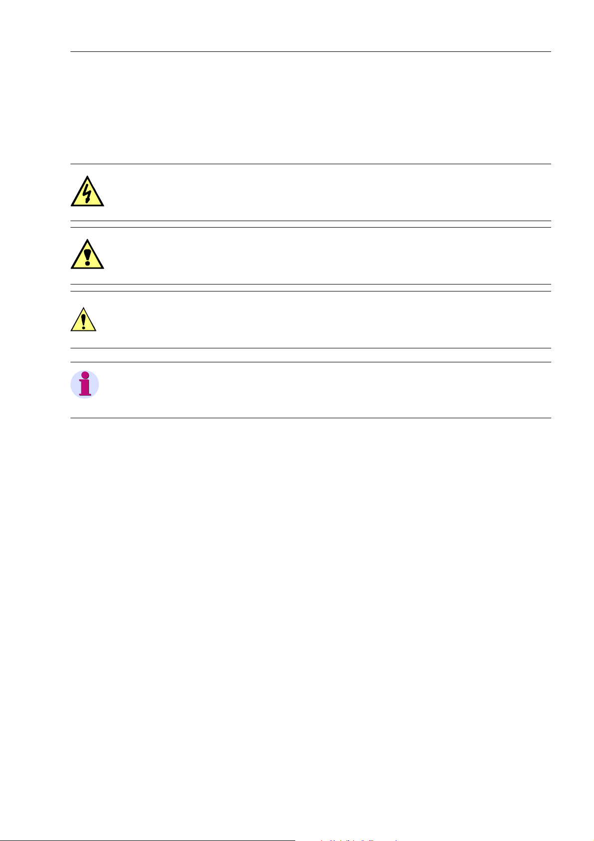
Safety Information
This manual does not constitute a complete index of all required safety measures for operation of the equipment (module, device), as special operational conditions may require additional measures. However, it comprises important information that should be noted for purposes of personal safety as well as avoiding material
damage. Information that is highlighted by means of a warning triangle and according to the degree of danger,
is illustrated as follows.
DANGER!
Danger indicates that death, severe personal injury or substantial material damage will result if proper precautions are not taken.
WARNING!
indicates that death, severe personal injury or substantial property damage may result if proper precautions are
not taken.
Caution!
indicates that minor personal injury or property damage may result if proper precautions are not taken. This
particularly applies to damage to or within the device itself and consequential damage thereof.
Preface
Note
indicates information on the device, handling of the device, or the respective part of the instruction manual
which is important to be noted.
SIPROTEC, 7RW80, Manual
C53000-G1140-C233-1, Release date 10.2010
5

Preface
WARNING!
Qualified Personnel
Commissioning and operation of the equipment (module, device) as set out in this manual may only be carried
out by qualified personnel. Qualified personnel in terms of the technical safety information as set out in this
manual are persons who are authorized to commission, activate, to ground and to designate devices, systems
and electrical circuits in accordance with the safety standards.
Use as prescribed
The operational equipment (device, module) may only be used for such applications as set out in the catalogue
and the technical description, and only in combination with third-party equipment recommended or approved
by Siemens.
The successful and safe operation of the device is dependent on proper handling, storage, installation, operation, and maintenance.
When operating an electrical equipment, certain parts of the device are inevitably subject to dangerous voltage.
Severe personal injury or property damage may result if the device is not handled properly.
Before any connections are made, the device must be grounded to the ground terminal.
All circuit components connected to the voltage supply may be subject to dangerous voltage.
Dangerous voltage may be present in the device even after the power supply voltage has been removed (capacitors can still be charged).
Operational equipment with exposed current transformer circuits may not be operated.
The limit values as specified in this manual or in the operating instructions may not be exceeded. This aspect
must also be observed during testing and commissioning.
6
C53000-G1140-C233-1, Release date 10.2010
SIPROTEC, 7RW80, Manual
T ypographic and Symbol Conventions
The following text formats are used when literal information from the device or to the device appear in the text
flow:
Parameter Names
Designators of configuration or function parameters which may appear word-for-word in the display of the
device or on the screen of a personal computer (with operation software DIGSI), are marked in bold letters in
monospace type style. The same goes for the titles of menus.
1234A
Parameter addresses have the same character style as parameter names. Parameter addresses contain the
suffix A in the overview tables if the parameter can only be set in DIGSI via the option Display additional set-
tings.
Parameter Options
Possible settings of text parameters, which may appear word-for-word in the display of the device or on the
screen of a personal computer (with operation software DIGSI), are additionally written in italics. This also
applies to header bars for selection menus.
„Messages“
Designators for information, which may be output by the relay or required from other devices or from the switch
gear, are marked in a monospace type style in quotation marks.
Preface
Deviations may be permitted in drawings and tables when the type of designator can be obviously derived from
the illustration.
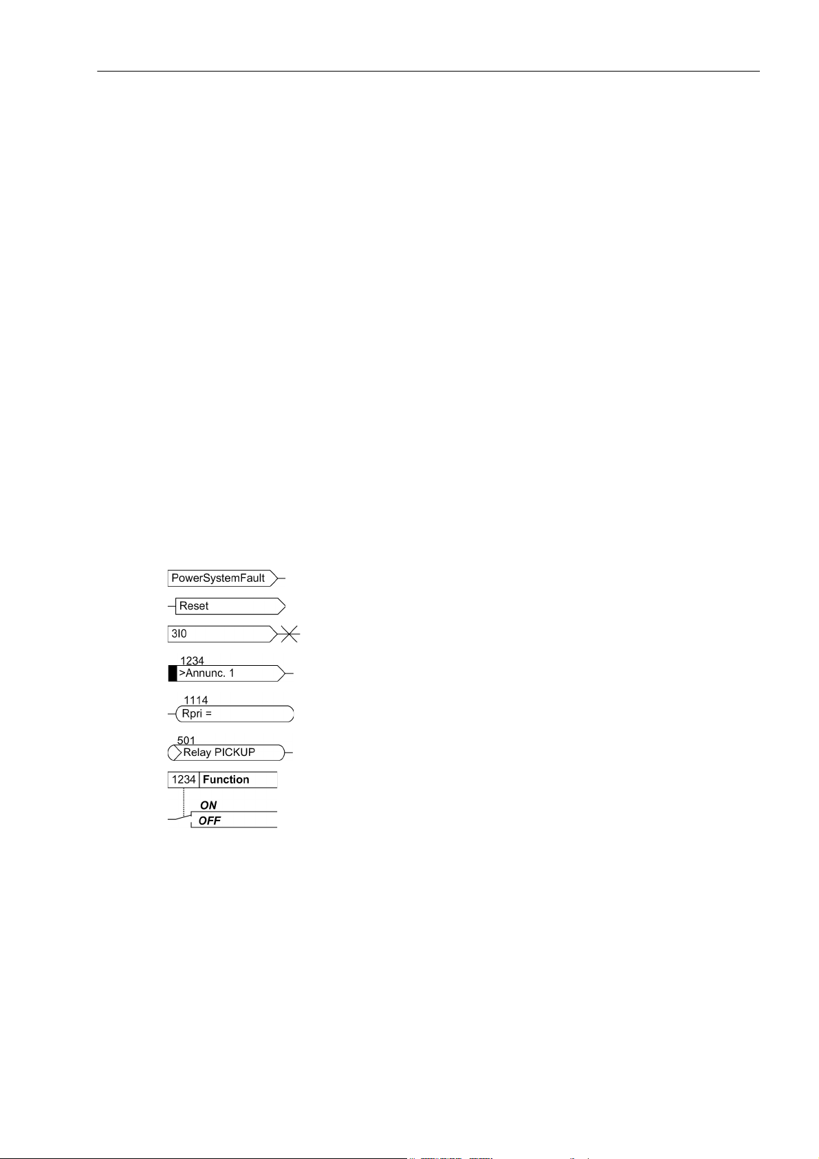
The following symbols are used in drawings:
Device-internal logical input signal
Device-internal logical output signal
Internal input signal of an analog quantity
External binary input signal with number (binary input,
input indication)
External binary input signal with number
(example of a value indication)
External binary output signal with number (device indication) used as
input signal
Example of a parameter switch designated FUNCTION with address
1234 and the possible settings ON and OFF
SIPROTEC, 7RW80, Manual
C53000-G1140-C233-1, Release date 10.2010
7
Preface
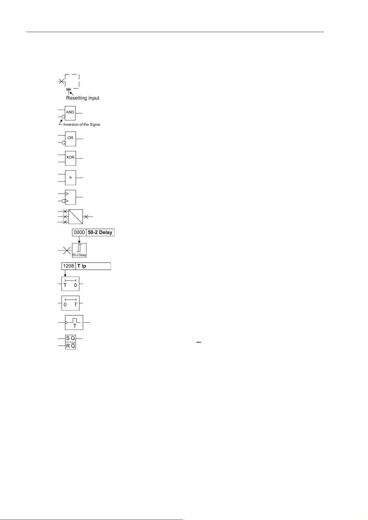
Besides these, graphical symbols are used according to IEC 60617-12 and IEC 60617-13 or symbols derived
from these standards. Some of the most frequently used are listed below:
Input signal of analog quantity
AND-gate operation of input values
OR-gate operation of input values
Exklusive OR-gate (antivalence): output is active, if only one of the
inputs is active
Coincidence gate (equivalence): output is active, if both inputs are
active or inactive at the same time
Dynamic inputs (edge-triggered) above with positive, below with negative edge
Formation of one analog output signal from a number of analog input
signals
Limit stage with setting address and parameter designator (name)
Timer (pickup delay T, example adjustable) with setting address and
parameter designator (name)
Timer (dropout delay T, example non-adjustable)
Dynamic triggered pulse timer T (monoflop)
Static memory (RS-flipflop) with setting input (S), resetting input (R),
output (Q) and inverted output (Q
)
■
8
C53000-G1140-C233-1, Release date 10.2010
SIPROTEC, 7RW80, Manual

Contents
1 Introduction. . . . . . . . . . . . . . . . . . . . . . . . . . . . . . . . . . . . . . . . . . . . . . . . . . . . . . . . . . . . . . . . . . . . . . . . . . . . . .15
1.1 Overall Operation. . . . . . . . . . . . . . . . . . . . . . . . . . . . . . . . . . . . . . . . . . . . . . . . . . . . . . . . . . . . . . . . . .16
1.2 Application Scope . . . . . . . . . . . . . . . . . . . . . . . . . . . . . . . . . . . . . . . . . . . . . . . . . . . . . . . . . . . . . . . . .18
1.3 Characteristics. . . . . . . . . . . . . . . . . . . . . . . . . . . . . . . . . . . . . . . . . . . . . . . . . . . . . . . . . . . . . . . . . . . .20
2 Functions. . . . . . . . . . . . . . . . . . . . . . . . . . . . . . . . . . . . . . . . . . . . . . . . . . . . . . . . . . . . . . . . . . . . . . . . . . . . . . . .23
2.1 General . . . . . . . . . . . . . . . . . . . . . . . . . . . . . . . . . . . . . . . . . . . . . . . . . . . . . . . . . . . . . . . . . . . . . . . . .24
2.1.1 Functional Scope . . . . . . . . . . . . . . . . . . . . . . . . . . . . . . . . . . . . . . . . . . . . . . . . . . . . . . . . . . . . . . .24
2.1.1.1 Description . . . . . . . . . . . . . . . . . . . . . . . . . . . . . . . . . . . . . . . . . . . . . . . . . . . . . . . . . . . . . . . . .24
2.1.1.2 Setting Notes . . . . . . . . . . . . . . . . . . . . . . . . . . . . . . . . . . . . . . . . . . . . . . . . . . . . . . . . . . . . . . .25
2.1.1.3 Settings . . . . . . . . . . . . . . . . . . . . . . . . . . . . . . . . . . . . . . . . . . . . . . . . . . . . . . . . . . . . . . . . . . .26
2.1.2 Device, General Settings . . . . . . . . . . . . . . . . . . . . . . . . . . . . . . . . . . . . . . . . . . . . . . . . . . . . . . . . .27
2.1.2.1 Description . . . . . . . . . . . . . . . . . . . . . . . . . . . . . . . . . . . . . . . . . . . . . . . . . . . . . . . . . . . . . . . . .27
2.1.2.2 Setting Notes . . . . . . . . . . . . . . . . . . . . . . . . . . . . . . . . . . . . . . . . . . . . . . . . . . . . . . . . . . . . . . .28
2.1.2.3 Settings . . . . . . . . . . . . . . . . . . . . . . . . . . . . . . . . . . . . . . . . . . . . . . . . . . . . . . . . . . . . . . . . . . .28
2.1.2.4 Information List. . . . . . . . . . . . . . . . . . . . . . . . . . . . . . . . . . . . . . . . . . . . . . . . . . . . . . . . . . . . . .28
2.1.3 Power System Data 1 . . . . . . . . . . . . . . . . . . . . . . . . . . . . . . . . . . . . . . . . . . . . . . . . . . . . . . . . . . .30
2.1.3.1 Description . . . . . . . . . . . . . . . . . . . . . . . . . . . . . . . . . . . . . . . . . . . . . . . . . . . . . . . . . . . . . . . . .30
2.1.3.2 Setting Notes . . . . . . . . . . . . . . . . . . . . . . . . . . . . . . . . . . . . . . . . . . . . . . . . . . . . . . . . . . . . . . .30
2.1.3.3 Settings . . . . . . . . . . . . . . . . . . . . . . . . . . . . . . . . . . . . . . . . . . . . . . . . . . . . . . . . . . . . . . . . . . .33
2.1.3.4 Information List. . . . . . . . . . . . . . . . . . . . . . . . . . . . . . . . . . . . . . . . . . . . . . . . . . . . . . . . . . . . . .34
2.1.4 Oscillographic Fault Records . . . . . . . . . . . . . . . . . . . . . . . . . . . . . . . . . . . . . . . . . . . . . . . . . . . . . .34
2.1.4.1 Description . . . . . . . . . . . . . . . . . . . . . . . . . . . . . . . . . . . . . . . . . . . . . . . . . . . . . . . . . . . . . . . . .34
2.1.4.2 Setting Notes . . . . . . . . . . . . . . . . . . . . . . . . . . . . . . . . . . . . . . . . . . . . . . . . . . . . . . . . . . . . . . .35
2.1.4.3 Settings . . . . . . . . . . . . . . . . . . . . . . . . . . . . . . . . . . . . . . . . . . . . . . . . . . . . . . . . . . . . . . . . . . .36
2.1.4.4 Information List. . . . . . . . . . . . . . . . . . . . . . . . . . . . . . . . . . . . . . . . . . . . . . . . . . . . . . . . . . . . . .36
2.1.5 Settings Groups . . . . . . . . . . . . . . . . . . . . . . . . . . . . . . . . . . . . . . . . . . . . . . . . . . . . . . . . . . . . . . . .36
2.1.5.1 Description . . . . . . . . . . . . . . . . . . . . . . . . . . . . . . . . . . . . . . . . . . . . . . . . . . . . . . . . . . . . . . . . .36
2.1.5.2 Setting Notes . . . . . . . . . . . . . . . . . . . . . . . . . . . . . . . . . . . . . . . . . . . . . . . . . . . . . . . . . . . . . . .37
2.1.5.3 Settings . . . . . . . . . . . . . . . . . . . . . . . . . . . . . . . . . . . . . . . . . . . . . . . . . . . . . . . . . . . . . . . . . . .37
2.1.5.4 Information List. . . . . . . . . . . . . . . . . . . . . . . . . . . . . . . . . . . . . . . . . . . . . . . . . . . . . . . . . . . . . .37
2.1.6 Power System Data 2 . . . . . . . . . . . . . . . . . . . . . . . . . . . . . . . . . . . . . . . . . . . . . . . . . . . . . . . . . . .38
2.1.6.1 Description . . . . . . . . . . . . . . . . . . . . . . . . . . . . . . . . . . . . . . . . . . . . . . . . . . . . . . . . . . . . . . . . .38
2.1.6.2 Setting Notes . . . . . . . . . . . . . . . . . . . . . . . . . . . . . . . . . . . . . . . . . . . . . . . . . . . . . . . . . . . . . . .38
2.1.6.3 Settings . . . . . . . . . . . . . . . . . . . . . . . . . . . . . . . . . . . . . . . . . . . . . . . . . . . . . . . . . . . . . . . . . . .38
2.1.6.4 Information List. . . . . . . . . . . . . . . . . . . . . . . . . . . . . . . . . . . . . . . . . . . . . . . . . . . . . . . . . . . . . .38
2.1.7 EN100-Module . . . . . . . . . . . . . . . . . . . . . . . . . . . . . . . . . . . . . . . . . . . . . . . . . . . . . . . . . . . . . . . . .39
2.1.7.1 Functional Description . . . . . . . . . . . . . . . . . . . . . . . . . . . . . . . . . . . . . . . . . . . . . . . . . . . . . . . .39
2.1.7.2 Setting Notes . . . . . . . . . . . . . . . . . . . . . . . . . . . . . . . . . . . . . . . . . . . . . . . . . . . . . . . . . . . . . . .39
2.1.7.3 Information List. . . . . . . . . . . . . . . . . . . . . . . . . . . . . . . . . . . . . . . . . . . . . . . . . . . . . . . . . . . . . .39
SIPROTEC, 7RW80, Manual
C53000-G1140-C233-1, Release date 10.2010
9

Contents
2.2 Voltage Protection 27, 59 . . . . . . . . . . . . . . . . . . . . . . . . . . . . . . . . . . . . . . . . . . . . . . . . . . . . . . . . . . . 40
2.2.1 Measurement Principle . . . . . . . . . . . . . . . . . . . . . . . . . . . . . . . . . . . . . . . . . . . . . . . . . . . . . . . . . . 40
2.2.2 Overvoltage Protection 59. . . . . . . . . . . . . . . . . . . . . . . . . . . . . . . . . . . . . . . . . . . . . . . . . . . . . . . . 41
2.2.3 Undervoltage Protection 27. . . . . . . . . . . . . . . . . . . . . . . . . . . . . . . . . . . . . . . . . . . . . . . . . . . . . . . 43
2.2.4 Setting Notes. . . . . . . . . . . . . . . . . . . . . . . . . . . . . . . . . . . . . . . . . . . . . . . . . . . . . . . . . . . . . . . . . . 45
2.2.5 Settings . . . . . . . . . . . . . . . . . . . . . . . . . . . . . . . . . . . . . . . . . . . . . . . . . . . . . . . . . . . . . . . . . . . . . . 48
2.2.6 Information List . . . . . . . . . . . . . . . . . . . . . . . . . . . . . . . . . . . . . . . . . . . . . . . . . . . . . . . . . . . . . . . . 49
2.3 Frequency Protection 81 O/U . . . . . . . . . . . . . . . . . . . . . . . . . . . . . . . . . . . . . . . . . . . . . . . . . . . . . . . . 50
2.3.1 Description . . . . . . . . . . . . . . . . . . . . . . . . . . . . . . . . . . . . . . . . . . . . . . . . . . . . . . . . . . . . . . . . . . . 50
2.3.2 Setting Notes. . . . . . . . . . . . . . . . . . . . . . . . . . . . . . . . . . . . . . . . . . . . . . . . . . . . . . . . . . . . . . . . . . 52
2.3.3 Settings . . . . . . . . . . . . . . . . . . . . . . . . . . . . . . . . . . . . . . . . . . . . . . . . . . . . . . . . . . . . . . . . . . . . . . 53
2.3.4 Information List . . . . . . . . . . . . . . . . . . . . . . . . . . . . . . . . . . . . . . . . . . . . . . . . . . . . . . . . . . . . . . . . 54
2.4 Load Restoration. . . . . . . . . . . . . . . . . . . . . . . . . . . . . . . . . . . . . . . . . . . . . . . . . . . . . . . . . . . . . . . . . . 55
2.4.1 Description . . . . . . . . . . . . . . . . . . . . . . . . . . . . . . . . . . . . . . . . . . . . . . . . . . . . . . . . . . . . . . . . . . . 55
2.4.2 Setting Notes. . . . . . . . . . . . . . . . . . . . . . . . . . . . . . . . . . . . . . . . . . . . . . . . . . . . . . . . . . . . . . . . . . 61
2.4.3 Settings . . . . . . . . . . . . . . . . . . . . . . . . . . . . . . . . . . . . . . . . . . . . . . . . . . . . . . . . . . . . . . . . . . . . . . 64
2.4.4 Information List . . . . . . . . . . . . . . . . . . . . . . . . . . . . . . . . . . . . . . . . . . . . . . . . . . . . . . . . . . . . . . . . 66
2.5 Monitoring Functions. . . . . . . . . . . . . . . . . . . . . . . . . . . . . . . . . . . . . . . . . . . . . . . . . . . . . . . . . . . . . . . 68
2.5.1 Measurement Supervision. . . . . . . . . . . . . . . . . . . . . . . . . . . . . . . . . . . . . . . . . . . . . . . . . . . . . . . . 68
2.5.1.1 General . . . . . . . . . . . . . . . . . . . . . . . . . . . . . . . . . . . . . . . . . . . . . . . . . . . . . . . . . . . . . . . . . . . 68
2.5.1.2 Hardware Monitoring . . . . . . . . . . . . . . . . . . . . . . . . . . . . . . . . . . . . . . . . . . . . . . . . . . . . . . . 68
2.5.1.3 Software Monitoring . . . . . . . . . . . . . . . . . . . . . . . . . . . . . . . . . . . . . . . . . . . . . . . . . . . . . . . . . 69
2.5.1.4 Monitoring of the Transformer Circuits. . . . . . . . . . . . . . . . . . . . . . . . . . . . . . . . . . . . . . . . . . . . 69
2.5.1.5 Broken Wire Monitoring of Voltage Transformer Circuits. . . . . . . . . . . . . . . . . . . . . . . . . . . . . . 71
2.5.1.6 Setting Notes . . . . . . . . . . . . . . . . . . . . . . . . . . . . . . . . . . . . . . . . . . . . . . . . . . . . . . . . . . . . . . . 72
2.5.1.7 Settings . . . . . . . . . . . . . . . . . . . . . . . . . . . . . . . . . . . . . . . . . . . . . . . . . . . . . . . . . . . . . . . . . . . 72
2.5.1.8 Information List . . . . . . . . . . . . . . . . . . . . . . . . . . . . . . . . . . . . . . . . . . . . . . . . . . . . . . . . . . . . . 72
2.5.2 Trip Circuit Supervision 74TC . . . . . . . . . . . . . . . . . . . . . . . . . . . . . . . . . . . . . . . . . . . . . . . . . . . . . 73
2.5.2.1 Description. . . . . . . . . . . . . . . . . . . . . . . . . . . . . . . . . . . . . . . . . . . . . . . . . . . . . . . . . . . . . . . . . 73
2.5.2.2 Setting Notes . . . . . . . . . . . . . . . . . . . . . . . . . . . . . . . . . . . . . . . . . . . . . . . . . . . . . . . . . . . . . . . 76
2.5.2.3 Settings . . . . . . . . . . . . . . . . . . . . . . . . . . . . . . . . . . . . . . . . . . . . . . . . . . . . . . . . . . . . . . . . . . . 77
2.5.2.4 Information List . . . . . . . . . . . . . . . . . . . . . . . . . . . . . . . . . . . . . . . . . . . . . . . . . . . . . . . . . . . . . 77
2.5.3 Malfunction Responses of the Monitoring Functions. . . . . . . . . . . . . . . . . . . . . . . . . . . . . . . . . . . . 77
2.5.3.1 Description. . . . . . . . . . . . . . . . . . . . . . . . . . . . . . . . . . . . . . . . . . . . . . . . . . . . . . . . . . . . . . . . . 77
2.6 Flexible Protection Functions . . . . . . . . . . . . . . . . . . . . . . . . . . . . . . . . . . . . . . . . . . . . . . . . . . . . . . . . 79
2.6.1 Functional Description. . . . . . . . . . . . . . . . . . . . . . . . . . . . . . . . . . . . . . . . . . . . . . . . . . . . . . . . . . . 79
2.6.2 Setting Notes. . . . . . . . . . . . . . . . . . . . . . . . . . . . . . . . . . . . . . . . . . . . . . . . . . . . . . . . . . . . . . . . . . 83
2.6.3 Settings . . . . . . . . . . . . . . . . . . . . . . . . . . . . . . . . . . . . . . . . . . . . . . . . . . . . . . . . . . . . . . . . . . . . . . 87
2.6.4 Information List . . . . . . . . . . . . . . . . . . . . . . . . . . . . . . . . . . . . . . . . . . . . . . . . . . . . . . . . . . . . . . . . 88
10
C53000-G1140-C233-1, Release date 10.2010
SIPROTEC, 7RW80, Manual

Contents
2.7 SYNCHROCHECK 25 . . . . . . . . . . . . . . . . . . . . . . . . . . . . . . . . . . . . . . . . . . . . . . . . . . . . . . . . . . . . . .89
2.7.1 General . . . . . . . . . . . . . . . . . . . . . . . . . . . . . . . . . . . . . . . . . . . . . . . . . . . . . . . . . . . . . . . . . . . . . .89
2.7.2 Functional Sequence . . . . . . . . . . . . . . . . . . . . . . . . . . . . . . . . . . . . . . . . . . . . . . . . . . . . . . . . . . . .90
2.7.3 De-energized Switching . . . . . . . . . . . . . . . . . . . . . . . . . . . . . . . . . . . . . . . . . . . . . . . . . . . . . . . . . .92
2.7.4 Direct Command / Blocking . . . . . . . . . . . . . . . . . . . . . . . . . . . . . . . . . . . . . . . . . . . . . . . . . . . . . . .93
2.7.5 Interaction with Control and External Control. . . . . . . . . . . . . . . . . . . . . . . . . . . . . . . . . . . . . . . . . .93
2.7.6 Setting Notes . . . . . . . . . . . . . . . . . . . . . . . . . . . . . . . . . . . . . . . . . . . . . . . . . . . . . . . . . . . . . . . . . .94
2.7.7 Settings . . . . . . . . . . . . . . . . . . . . . . . . . . . . . . . . . . . . . . . . . . . . . . . . . . . . . . . . . . . . . . . . . . . . . .99
2.7.8 Information List. . . . . . . . . . . . . . . . . . . . . . . . . . . . . . . . . . . . . . . . . . . . . . . . . . . . . . . . . . . . . . . .100
2.8 24 Overexcit. Protection (Volt/Hertz) . . . . . . . . . . . . . . . . . . . . . . . . . . . . . . . . . . . . . . . . . . . . . . . . . .102
2.8.1 Functional Description . . . . . . . . . . . . . . . . . . . . . . . . . . . . . . . . . . . . . . . . . . . . . . . . . . . . . . . . . .102
2.8.2 Setting Notes . . . . . . . . . . . . . . . . . . . . . . . . . . . . . . . . . . . . . . . . . . . . . . . . . . . . . . . . . . . . . . . . .104
2.8.3 Settings . . . . . . . . . . . . . . . . . . . . . . . . . . . . . . . . . . . . . . . . . . . . . . . . . . . . . . . . . . . . . . . . . . . . .106
2.8.4 Information List. . . . . . . . . . . . . . . . . . . . . . . . . . . . . . . . . . . . . . . . . . . . . . . . . . . . . . . . . . . . . . . .106
2.9 Jump of Voltage Vector . . . . . . . . . . . . . . . . . . . . . . . . . . . . . . . . . . . . . . . . . . . . . . . . . . . . . . . . . . . .107
2.9.1 Functional Description . . . . . . . . . . . . . . . . . . . . . . . . . . . . . . . . . . . . . . . . . . . . . . . . . . . . . . . . . .107
2.9.2 Setting Notes . . . . . . . . . . . . . . . . . . . . . . . . . . . . . . . . . . . . . . . . . . . . . . . . . . . . . . . . . . . . . . . . .109
2.9.3 Settings . . . . . . . . . . . . . . . . . . . . . . . . . . . . . . . . . . . . . . . . . . . . . . . . . . . . . . . . . . . . . . . . . . . . .110
2.9.4 Information List. . . . . . . . . . . . . . . . . . . . . . . . . . . . . . . . . . . . . . . . . . . . . . . . . . . . . . . . . . . . . . . .110
2.10 Phase Rotation . . . . . . . . . . . . . . . . . . . . . . . . . . . . . . . . . . . . . . . . . . . . . . . . . . . . . . . . . . . . . . . . . .111
2.10.1 Description . . . . . . . . . . . . . . . . . . . . . . . . . . . . . . . . . . . . . . . . . . . . . . . . . . . . . . . . . . . . . . . . . . .111
2.10.2 Setting Notes . . . . . . . . . . . . . . . . . . . . . . . . . . . . . . . . . . . . . . . . . . . . . . . . . . . . . . . . . . . . . . . . .112
2.11 Function Logic . . . . . . . . . . . . . . . . . . . . . . . . . . . . . . . . . . . . . . . . . . . . . . . . . . . . . . . . . . . . . . . . . . .113
2.11.1 Pickup Logic of the Entire Device . . . . . . . . . . . . . . . . . . . . . . . . . . . . . . . . . . . . . . . . . . . . . . . . .113
2.11.2 Tripping Logic of the Entire Device . . . . . . . . . . . . . . . . . . . . . . . . . . . . . . . . . . . . . . . . . . . . . . . .113
2.11.3 Setting Notes . . . . . . . . . . . . . . . . . . . . . . . . . . . . . . . . . . . . . . . . . . . . . . . . . . . . . . . . . . . . . . . . .114
SIPROTEC, 7RW80, Manual
C53000-G1140-C233-1, Release date 10.2010
11

Contents
2.12 Auxiliary Functions . . . . . . . . . . . . . . . . . . . . . . . . . . . . . . . . . . . . . . . . . . . . . . . . . . . . . . . . . . . . . . . 115
2.12.1 Message Processing . . . . . . . . . . . . . . . . . . . . . . . . . . . . . . . . . . . . . . . . . . . . . . . . . . . . . . . . . . . 115
2.12.1.1 LEDs and Binary Outputs (Output Relays) . . . . . . . . . . . . . . . . . . . . . . . . . . . . . . . . . . . . . . . 115
2.12.1.2 Information via Display Field or PC . . . . . . . . . . . . . . . . . . . . . . . . . . . . . . . . . . . . . . . . . . . . . 116
2.12.1.3 Information to a Control Center . . . . . . . . . . . . . . . . . . . . . . . . . . . . . . . . . . . . . . . . . . . . . . . . 117
2.12.2 Statistics . . . . . . . . . . . . . . . . . . . . . . . . . . . . . . . . . . . . . . . . . . . . . . . . . . . . . . . . . . . . . . . . . . . . 117
2.12.2.1 Description. . . . . . . . . . . . . . . . . . . . . . . . . . . . . . . . . . . . . . . . . . . . . . . . . . . . . . . . . . . . . . . . 117
2.12.2.2 Setting Notes . . . . . . . . . . . . . . . . . . . . . . . . . . . . . . . . . . . . . . . . . . . . . . . . . . . . . . . . . . . . . . 118
2.12.2.3 Information List . . . . . . . . . . . . . . . . . . . . . . . . . . . . . . . . . . . . . . . . . . . . . . . . . . . . . . . . . . . . 118
2.12.3 Measurement . . . . . . . . . . . . . . . . . . . . . . . . . . . . . . . . . . . . . . . . . . . . . . . . . . . . . . . . . . . . . . . . 118
2.12.3.1 Displaying of Measured Values . . . . . . . . . . . . . . . . . . . . . . . . . . . . . . . . . . . . . . . . . . . . . . . . 119
2.12.3.2 Transfer of Measured Values. . . . . . . . . . . . . . . . . . . . . . . . . . . . . . . . . . . . . . . . . . . . . . . . . . 120
2.12.3.3 Information List . . . . . . . . . . . . . . . . . . . . . . . . . . . . . . . . . . . . . . . . . . . . . . . . . . . . . . . . . . . . 120
2.12.4 Min/Max Measurement Setup . . . . . . . . . . . . . . . . . . . . . . . . . . . . . . . . . . . . . . . . . . . . . . . . . . . . 121
2.12.4.1 Description. . . . . . . . . . . . . . . . . . . . . . . . . . . . . . . . . . . . . . . . . . . . . . . . . . . . . . . . . . . . . . . . 121
2.12.4.2 Setting Notes . . . . . . . . . . . . . . . . . . . . . . . . . . . . . . . . . . . . . . . . . . . . . . . . . . . . . . . . . . . . . . 121
2.12.4.3 Settings . . . . . . . . . . . . . . . . . . . . . . . . . . . . . . . . . . . . . . . . . . . . . . . . . . . . . . . . . . . . . . . . . . 121
2.12.4.4 Information List . . . . . . . . . . . . . . . . . . . . . . . . . . . . . . . . . . . . . . . . . . . . . . . . . . . . . . . . . . . . 122
2.12.5 Set Points for Measured Values . . . . . . . . . . . . . . . . . . . . . . . . . . . . . . . . . . . . . . . . . . . . . . . . . . 123
2.12.5.1 Setting Notes . . . . . . . . . . . . . . . . . . . . . . . . . . . . . . . . . . . . . . . . . . . . . . . . . . . . . . . . . . . . . . 123
2.12.6 Set Points for Statistic . . . . . . . . . . . . . . . . . . . . . . . . . . . . . . . . . . . . . . . . . . . . . . . . . . . . . . . . . . 123
2.12.6.1 Description. . . . . . . . . . . . . . . . . . . . . . . . . . . . . . . . . . . . . . . . . . . . . . . . . . . . . . . . . . . . . . . . 123
2.12.6.2 Setting Notes . . . . . . . . . . . . . . . . . . . . . . . . . . . . . . . . . . . . . . . . . . . . . . . . . . . . . . . . . . . . . . 123
2.12.6.3 Information List . . . . . . . . . . . . . . . . . . . . . . . . . . . . . . . . . . . . . . . . . . . . . . . . . . . . . . . . . . . . 124
2.12.7 Energy Metering . . . . . . . . . . . . . . . . . . . . . . . . . . . . . . . . . . . . . . . . . . . . . . . . . . . . . . . . . . . . . . 124
2.12.7.1 Setting Notes . . . . . . . . . . . . . . . . . . . . . . . . . . . . . . . . . . . . . . . . . . . . . . . . . . . . . . . . . . . . . . 124
2.12.7.2 Settings . . . . . . . . . . . . . . . . . . . . . . . . . . . . . . . . . . . . . . . . . . . . . . . . . . . . . . . . . . . . . . . . . . 124
2.12.7.3 Information List . . . . . . . . . . . . . . . . . . . . . . . . . . . . . . . . . . . . . . . . . . . . . . . . . . . . . . . . . . . . 124
2.12.8 Commissíoning Aids . . . . . . . . . . . . . . . . . . . . . . . . . . . . . . . . . . . . . . . . . . . . . . . . . . . . . . . . . . . 125
2.12.8.1 Description. . . . . . . . . . . . . . . . . . . . . . . . . . . . . . . . . . . . . . . . . . . . . . . . . . . . . . . . . . . . . . . . 125
2.13 Breaker Control. . . . . . . . . . . . . . . . . . . . . . . . . . . . . . . . . . . . . . . . . . . . . . . . . . . . . . . . . . . . . . . . . . 127
2.13.1 Control Device. . . . . . . . . . . . . . . . . . . . . . . . . . . . . . . . . . . . . . . . . . . . . . . . . . . . . . . . . . . . . . . . 127
2.13.1.1 Description. . . . . . . . . . . . . . . . . . . . . . . . . . . . . . . . . . . . . . . . . . . . . . . . . . . . . . . . . . . . . . . . 127
2.13.1.2 Information List . . . . . . . . . . . . . . . . . . . . . . . . . . . . . . . . . . . . . . . . . . . . . . . . . . . . . . . . . . . . 128
2.13.2 Command Types . . . . . . . . . . . . . . . . . . . . . . . . . . . . . . . . . . . . . . . . . . . . . . . . . . . . . . . . . . . . . . 129
2.13.2.1 Description. . . . . . . . . . . . . . . . . . . . . . . . . . . . . . . . . . . . . . . . . . . . . . . . . . . . . . . . . . . . . . . . 129
2.13.3 Command Sequence. . . . . . . . . . . . . . . . . . . . . . . . . . . . . . . . . . . . . . . . . . . . . . . . . . . . . . . . . . . 130
2.13.3.1 Description. . . . . . . . . . . . . . . . . . . . . . . . . . . . . . . . . . . . . . . . . . . . . . . . . . . . . . . . . . . . . . . . 130
2.13.4 Interlocking . . . . . . . . . . . . . . . . . . . . . . . . . . . . . . . . . . . . . . . . . . . . . . . . . . . . . . . . . . . . . . . . . . 131
2.13.4.1 Description. . . . . . . . . . . . . . . . . . . . . . . . . . . . . . . . . . . . . . . . . . . . . . . . . . . . . . . . . . . . . . . . 131
2.13.5 Command Logging . . . . . . . . . . . . . . . . . . . . . . . . . . . . . . . . . . . . . . . . . . . . . . . . . . . . . . . . . . . . 136
2.13.5.1 Description. . . . . . . . . . . . . . . . . . . . . . . . . . . . . . . . . . . . . . . . . . . . . . . . . . . . . . . . . . . . . . . . 136
2.14 Notes on Device Operation . . . . . . . . . . . . . . . . . . . . . . . . . . . . . . . . . . . . . . . . . . . . . . . . . . . . . . . . . 137
2.14.1 Different operation. . . . . . . . . . . . . . . . . . . . . . . . . . . . . . . . . . . . . . . . . . . . . . . . . . . . . . . . . . . . . 137
12
C53000-G1140-C233-1, Release date 10.2010
SIPROTEC, 7RW80, Manual

Contents
3 Mounting and Commissioning . . . . . . . . . . . . . . . . . . . . . . . . . . . . . . . . . . . . . . . . . . . . . . . . . . . . . . . . . . . . .139
3.1 Mounting and Connections . . . . . . . . . . . . . . . . . . . . . . . . . . . . . . . . . . . . . . . . . . . . . . . . . . . . . . . . .140
3.1.1 Configuration Information. . . . . . . . . . . . . . . . . . . . . . . . . . . . . . . . . . . . . . . . . . . . . . . . . . . . . . . .140
3.1.2 Hardware Modifications . . . . . . . . . . . . . . . . . . . . . . . . . . . . . . . . . . . . . . . . . . . . . . . . . . . . . . . . .144
3.1.2.1 Disassembly . . . . . . . . . . . . . . . . . . . . . . . . . . . . . . . . . . . . . . . . . . . . . . . . . . . . . . . . . . . . . . .144
3.1.2.2 Connections of the Voltage Terminals . . . . . . . . . . . . . . . . . . . . . . . . . . . . . . . . . . . . . . . . . . .147
3.1.2.3 Interface Modules. . . . . . . . . . . . . . . . . . . . . . . . . . . . . . . . . . . . . . . . . . . . . . . . . . . . . . . . . . .147
3.1.2.4 Reassembly . . . . . . . . . . . . . . . . . . . . . . . . . . . . . . . . . . . . . . . . . . . . . . . . . . . . . . . . . . . . . . .150
3.1.3 Installation . . . . . . . . . . . . . . . . . . . . . . . . . . . . . . . . . . . . . . . . . . . . . . . . . . . . . . . . . . . . . . . . . . .151
3.1.3.1 General. . . . . . . . . . . . . . . . . . . . . . . . . . . . . . . . . . . . . . . . . . . . . . . . . . . . . . . . . . . . . . . . . . .151
3.1.3.2 Panel Flush Mounting. . . . . . . . . . . . . . . . . . . . . . . . . . . . . . . . . . . . . . . . . . . . . . . . . . . . . . . .152
3.1.3.3 Cubicle Mounting . . . . . . . . . . . . . . . . . . . . . . . . . . . . . . . . . . . . . . . . . . . . . . . . . . . . . . . . . . .153
3.1.3.4 Panel Surface Mounting . . . . . . . . . . . . . . . . . . . . . . . . . . . . . . . . . . . . . . . . . . . . . . . . . . . . . .154
3.2 Checking Connections. . . . . . . . . . . . . . . . . . . . . . . . . . . . . . . . . . . . . . . . . . . . . . . . . . . . . . . . . . . . .155
3.2.1 Checking the Data Connections of the Interfaces . . . . . . . . . . . . . . . . . . . . . . . . . . . . . . . . . . . . .155
3.2.2 Checking the System Connections . . . . . . . . . . . . . . . . . . . . . . . . . . . . . . . . . . . . . . . . . . . . . . . .158
3.3 Commissioning . . . . . . . . . . . . . . . . . . . . . . . . . . . . . . . . . . . . . . . . . . . . . . . . . . . . . . . . . . . . . . . . . .159
3.3.1 Test Mode and Transmission Block . . . . . . . . . . . . . . . . . . . . . . . . . . . . . . . . . . . . . . . . . . . . . . . .160
3.3.2 Testing the System Interface (at Port B) . . . . . . . . . . . . . . . . . . . . . . . . . . . . . . . . . . . . . . . . . . . .160
3.3.3 Configuring Communication Modules . . . . . . . . . . . . . . . . . . . . . . . . . . . . . . . . . . . . . . . . . . . . . .162
3.3.4 Checking the Status of Binary Inputs and Outputs. . . . . . . . . . . . . . . . . . . . . . . . . . . . . . . . . . . . .165
3.3.5 Testing User-Defined Functions . . . . . . . . . . . . . . . . . . . . . . . . . . . . . . . . . . . . . . . . . . . . . . . . . . .168
3.3.6 Voltage and Phase Rotation Testing . . . . . . . . . . . . . . . . . . . . . . . . . . . . . . . . . . . . . . . . . . . . . . .168
3.3.7 Polarity Check for Voltage Input V
. . . . . . . . . . . . . . . . . . . . . . . . . . . . . . . . . . . . . . . . . . . . . . . .169
3
3.3.8 Trip/Close Tests for the Configured Operating Devices . . . . . . . . . . . . . . . . . . . . . . . . . . . . . . . .171
3.3.9 Creating A Test Fault Record. . . . . . . . . . . . . . . . . . . . . . . . . . . . . . . . . . . . . . . . . . . . . . . . . . . . .172
3.4 Final Preparation of the Device . . . . . . . . . . . . . . . . . . . . . . . . . . . . . . . . . . . . . . . . . . . . . . . . . . . . . .173
4 Technical Data. . . . . . . . . . . . . . . . . . . . . . . . . . . . . . . . . . . . . . . . . . . . . . . . . . . . . . . . . . . . . . . . . . . . . . . . . . .175
4.1 General Device Data . . . . . . . . . . . . . . . . . . . . . . . . . . . . . . . . . . . . . . . . . . . . . . . . . . . . . . . . . . . . . .176
4.1.1 Analog Inputs . . . . . . . . . . . . . . . . . . . . . . . . . . . . . . . . . . . . . . . . . . . . . . . . . . . . . . . . . . . . .176
4.1.2 Auxiliary Voltage . . . . . . . . . . . . . . . . . . . . . . . . . . . . . . . . . . . . . . . . . . . . . . . . . . . . . . .176
4.1.3 Binary Inputs and Outputs . . . . . . . . . . . . . . . . . . . . . . . . . . . . . . . . . . . . . . . . . . . . . . .177
4.1.4 Communication Interfaces . . . . . . . . . . . . . . . . . . . . . . . . . . . . . . . . . . . . . . . . . . . . . . . . . . . . .178
4.1.5 Electrical Tests . . . . . . . . . . . . . . . . . . . . . . . . . . . . . . . . . . . . . . . . . . . . . . . . . . . . . . . . . . . .180
4.1.6 Mechanical Stress Tests . . . . . . . . . . . . . . . . . . . . . . . . . . . . . . . . . . . . . . . . . . . . . . . . . . . .182
4.1.7 Climatic Stress Tests . . . . . . . . . . . . . . . . . . . . . . . . . . . . . . . . . . . . . . . . . . . . . . . . . . . . . . .183
4.1.8 Service Conditions . . . . . . . . . . . . . . . . . . . . . . . . . . . . . . . . . . . . . . . . . . . . . . . . . . . . . . . . .183
4.1.9 Design . . . . . . . . . . . . . . . . . . . . . . . . . . . . . . . . . . . . . . . . . . . . . . . . . . . . . . . . . . . . . . . . . . . .184
4.1.10 UL certification conditions . . . . . . . . . . . . . . . . . . . . . . . . . . . . . . . . . . . . . . . . . . . . . . . . . . . . . . .184
4.2 Voltage Protection (27, 59) . . . . . . . . . . . . . . . . . . . . . . . . . . . . . . . . . . . . . . . . . . . . . . . . . . . . . . . . .185
4.3 Frequency Protection 81 O/U . . . . . . . . . . . . . . . . . . . . . . . . . . . . . . . . . . . . . . . . . . . . . . . . . . . . . . .187
4.4 Load Restoration . . . . . . . . . . . . . . . . . . . . . . . . . . . . . . . . . . . . . . . . . . . . . . . . . . . . . . . . . . . . . . . . .188
4.5 Flexible Protective Functions . . . . . . . . . . . . . . . . . . . . . . . . . . . . . . . . . . . . . . . . . . . . . . . . . . . . .189
4.6 Synchrocheck 25 . . . . . . . . . . . . . . . . . . . . . . . . . . . . . . . . . . . . . . . . . . . . . . . . . . . . . . . . . . . . . . . . .191
4.7 Overecxitation Protection 24 . . . . . . . . . . . . . . . . . . . . . . . . . . . . . . . . . . . . . . . . . . . . . . . . . . . . . . . .193
SIPROTEC, 7RW80, Manual
C53000-G1140-C233-1, Release date 10.2010
13

Contents
4.8 Jump of Voltage Vector . . . . . . . . . . . . . . . . . . . . . . . . . . . . . . . . . . . . . . . . . . . . . . . . . . . . . . . . . . . . 195
4.9 User-defined Functions (CFC) . . . . . . . . . . . . . . . . . . . . . . . . . . . . . . . . . . . . . . . . . . . . . . . . . . . 196
4.10 Additional Functions . . . . . . . . . . . . . . . . . . . . . . . . . . . . . . . . . . . . . . . . . . . . . . . . . . . . . . . . . . . . . . 201
4.11 Breaker Control . . . . . . . . . . . . . . . . . . . . . . . . . . . . . . . . . . . . . . . . . . . . . . . . . . . . . . . . . . . . 204
4.12 Dimensions . . . . . . . . . . . . . . . . . . . . . . . . . . . . . . . . . . . . . . . . . . . . . . . . . . . . . . . . . . . . . . . . . . . . . 205
4.12.1 Panel Flush and Cubicle Mounting (Housing Size 1/6) . . . . . . . . . . . . . . . . . . . . . . . . . . . . . . . . 205
4.12.2 Panel Surface Mounting (Housing Size 1/6) . . . . . . . . . . . . . . . . . . . . . . . . . . . . . . . . . . . . . . . .206
4.12.3 Bottom view. . . . . . . . . . . . . . . . . . . . . . . . . . . . . . . . . . . . . . . . . . . . . . . . . . . . . . . . . . . . . . . . . . 206
A Appendix. . . . . . . . . . . . . . . . . . . . . . . . . . . . . . . . . . . . . . . . . . . . . . . . . . . . . . . . . . . . . . . . . . . . . . . . . . . . . . .207
A.1 Ordering Information and Accessories . . . . . . . . . . . . . . . . . . . . . . . . . . . . . . . . . . . . . . . . . . . . . . . . 208
A.1.1 Ordering Information . . . . . . . . . . . . . . . . . . . . . . . . . . . . . . . . . . . . . . . . . . . . . . . . . . . . . . . . . . . 208
A.1.1.1 7RW80 V4.6 . . . . . . . . . . . . . . . . . . . . . . . . . . . . . . . . . . . . . . . . . . . . . . . . . . . . . . . . . . . . 208
A.1.2 Accessories . . . . . . . . . . . . . . . . . . . . . . . . . . . . . . . . . . . . . . . . . . . . . . . . . . . . . . . . . . . . . . . . . . 212
A.2 Terminal Assignments . . . . . . . . . . . . . . . . . . . . . . . . . . . . . . . . . . . . . . . . . . . . . . . . . . . . . . . . . . . . . 213
A.2.1 7RW80 — Housing for Panel Flush Mounting or Cubicle Mounting . . . . . . . . . . . . . . . . . . . . . . . 213
A.2.2 7RW80 — Housing for panel surface mounting . . . . . . . . . . . . . . . . . . . . . . . . . . . . . . . . . . . . . . 214
A.3 Connection Examples . . . . . . . . . . . . . . . . . . . . . . . . . . . . . . . . . . . . . . . . . . . . . . . . . . . . . . . . . . . . . 215
A.4 Default Settings. . . . . . . . . . . . . . . . . . . . . . . . . . . . . . . . . . . . . . . . . . . . . . . . . . . . . . . . . . . . . . . . . . 219
A.4.1 LEDs . . . . . . . . . . . . . . . . . . . . . . . . . . . . . . . . . . . . . . . . . . . . . . . . . . . . . . . . . . . . . . . . . . . . . . . 219
A.4.2 Binary Input . . . . . . . . . . . . . . . . . . . . . . . . . . . . . . . . . . . . . . . . . . . . . . . . . . . . . . . . . . . . . . . . . . 219
A.4.3 Binary Output . . . . . . . . . . . . . . . . . . . . . . . . . . . . . . . . . . . . . . . . . . . . . . . . . . . . . . . . . . . . . . . . 220
A.4.4 Function Keys . . . . . . . . . . . . . . . . . . . . . . . . . . . . . . . . . . . . . . . . . . . . . . . . . . . . . . . . . . . . . . . . 220
A.4.5 Default Display . . . . . . . . . . . . . . . . . . . . . . . . . . . . . . . . . . . . . . . . . . . . . . . . . . . . . . . . . . . . . . . 221
A.5 Protocol-dependent Functions . . . . . . . . . . . . . . . . . . . . . . . . . . . . . . . . . . . . . . . . . . . . . . . . . . . . . . 223
A.6 Functional Scope . . . . . . . . . . . . . . . . . . . . . . . . . . . . . . . . . . . . . . . . . . . . . . . . . . . . . . . . . . . . . . . . 224
A.7 Settings . . . . . . . . . . . . . . . . . . . . . . . . . . . . . . . . . . . . . . . . . . . . . . . . . . . . . . . . . . . . . . . . . . . . . . . . 225
A.8 Information List . . . . . . . . . . . . . . . . . . . . . . . . . . . . . . . . . . . . . . . . . . . . . . . . . . . . . . . . . . . . . . . . . . 231
A.9 Group Alarms . . . . . . . . . . . . . . . . . . . . . . . . . . . . . . . . . . . . . . . . . . . . . . . . . . . . . . . . . . . . . . . . . . . 242
A.10 Measured Values . . . . . . . . . . . . . . . . . . . . . . . . . . . . . . . . . . . . . . . . . . . . . . . . . . . . . . . . . . . . . . . . 243
Literature. . . . . . . . . . . . . . . . . . . . . . . . . . . . . . . . . . . . . . . . . . . . . . . . . . . . . . . . . . . . . . . . . . . . . . . . . . . . . . .245
Glossary . . . . . . . . . . . . . . . . . . . . . . . . . . . . . . . . . . . . . . . . . . . . . . . . . . . . . . . . . . . . . . . . . . . . . . . . . . . . . . . 247
Index . . . . . . . . . . . . . . . . . . . . . . . . . . . . . . . . . . . . . . . . . . . . . . . . . . . . . . . . . . . . . . . . . . . . . . . . . . . . . . . . . .259
14
C53000-G1140-C233-1, Release date 10.2010
SIPROTEC, 7RW80, Manual

Introduction 1
1.1 Overall Operation 16
1.2 Application Scope 18
1.3 Characteristics 20
SIPROTEC, 7RW80, Manual
C53000-G1140-C233-1, Release date 10.2010
15
Introduction
1.1 Overall Operation
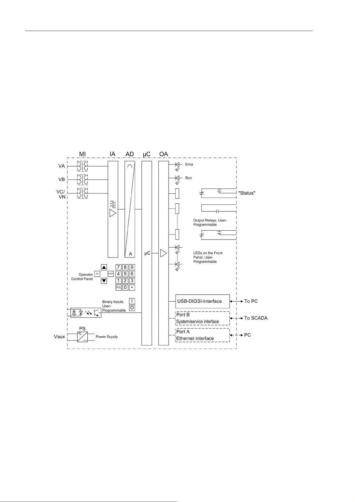
1.1 Overall Operation
The Voltage and Frequency protection SIPROTEC 7RW80 is equipped with a high performance microprocessor. This provides numerical processing of all functions in the device, from the acquisition of the measured
values up to the output of commands to the circuit breakers. Figure shows the basic structure of the device
7RW80.
Analog Inputs
The measuring inputs MI transform the voltages derived from the instrument transformers and match them to
the internal signal levels for processing in the device. Three voltage inputs are available in the MI section.
16
Figure 1-1 Hardware structure of the numerical Voltage and Frequency Protection Device 7RW80
Voltage inputs can either be used to measure the three phase-to-ground voltages, or two phase-to-phase voltages and the displacement voltage (e–n voltage) or for any other voltage. It is also possible to connect two
phase-to-phase voltages in open-delta connection.
The analog input quantities are passed on to the input amplifiers (IA). The input amplifier IA element provides
a high-resistance termination for the input quantities. It consists of filters that are optimized for measured-value
processing with regard to bandwidth and processing speed.
The analog-to-digital (AD) transformer group consists of a an analog-to-digital converter and memory components for the transmission of data to the microcomputer.
C53000-G1140-C233-1, Release date 10.2010
SIPROTEC, 7RW80, Manual

Microcomputer System
Apart from processing the measured values, the microcomputer system (μC) also executes the actual protection and control functions. They especially include:
• Filtering and preparation of the measured quantities
• Continuous monitoring of the measured quantities
• Monitoring of the pickup conditions for the individual protective functions
• Interrogation of limit values and sequences in time
• Control of signals for the logic functions
• Output of control commands for switching devices
• Recording of messages, fault data and fault values for analysis
• Management of the operating system and the associated functions such as data recording, real-time clock,
communication, interfaces, etc.
• The information is distributed via output amplifiers (OA).
Binary Inputs and Outputs
Binary inputs and outputs to and from the computer system are relayed via the input/output modules. The computer system obtains the information from the system (e.g. remote resetting) or the external equipment (e.g.
blocking commands). Outputs are, in particular, commands to the switchgear units and annunciations for
remote signalling of important events and statuses.
Introduction
1.1 Overall Operation
Front Panel
Information such as messages related to events, states, measured values and the functional status of the
device are visualized by light-emitting diodes (LEDs) and a display screen (LCD) on the front panel.
Integrated control and numeric keys in conjunction with the LCD enable interaction with the remote device.
These elements can be used to access the device for information such as configuration and setting parameters.
Similarly, setting parameters can be accessed and changed if needed.
In addition, control of circuit breakers and other equipment is possible from the front panel of the device.
Interfaces
Communication with a PC can be implemented via the USB DIGSI interface using the DIGSI software, allowing all device functions to be easily executed.
Communication with a PC is also possible via port A (Ethernet interface) and port B (System/Service interface)
using DIGSI.
In addition to the device communication via DIGSI, port B can also be used to transmit all device data to a
central evaluator or a control center. This interface may be provided with various protocols and physical transmission schemes to suit the particular application.
Power Supply
A power supply unit (Vaux or PS) delivers power to the functional units using the different voltage levels. Voltage
dips may occur if the voltage supply system (substation battery) becomes short-circuited. Usually, they are
bridged by a capacitor (see also Technical Data).
A buffer battery is located under the flap at the lower end of the front cover.
SIPROTEC, 7RW80, Manual
C53000-G1140-C233-1, Release date 10.2010
17

Introduction
1.2 Application Scope
1.2 Application Scope
The digital voltage and frequency protection SIPROTEC 4 7RW80 is a versatile device designed for protection,
control, and monitoring of transformers, electrical machines and distribution systems.
The device can be used for
• System decoupling or for load shedding if ever there is a risk of a system collapse as a result of inadmissibly
large frequency drops
• Monitoring voltage and frequency thresholds.
Voltage, frequency and overexcitation protection can be used to protect generators and transformers in the
event of
• defective voltage control or defective frequency control
• Full load rejection
• Islanding generation systems.
Protection Functions
Multilevel voltage and frequency protection is the basic function of the device.
Further protection functions included are load restoration, synchrocheck, overexcitation protection, vector jump
and flexible protective functions.
Control Functions
The device provides a control function which can be accomplished for activating and deactivating switchgear
via operator buttons, port B, binary inputs and - using a PC and the DIGSI software - via the front interface.
The status of the primary equipment can be transmitted to the device via auxiliary contacts connected to binary
inputs. The present status (or position) of the primary equipment can be displayed on the device, and used for
interlocking or alarm condition monitoring. The number of operating equipment to be switched is limited by the
binary inputs and outputs available in the device or the binary inputs and outputs allocated for the switch position indications. Depending on the primary equipment being controlled, one binary input (single point indication)
or two binary inputs (double point indication) may be used for this process.
The capability of switching primary equipment can be restricted by a setting associated with switching authority
(Remote or Local), and by the operating mode (interlocked/non-interlocked, with or without password request).
Processing of interlocking conditions for switching (e.g. switchgear interlocking) can be established with the aid
of integrated, user-configurable logic functions.
Messages and Measured Values; Recording of Event and Fault Data
The operational indications provide information about conditions in the power system and the device. Measurement quantities and values that are calculated can be displayed locally and communicated via the serial interfaces.
18
Device messages can be assigned to a number of LEDs on the front cover (allocatable), can be externally processed via output contacts (allocatable), linked with user-definable logic functions and/or issued via serial interfaces.
During a fault (system fault) important events and changes in conditions are saved in fault protocols (Event Log
or Trip Log). Instantaneous fault values are also saved in the device and may be analized subsequently.
C53000-G1140-C233-1, Release date 10.2010
SIPROTEC, 7RW80, Manual

Communication
The following interfaces are available for communication with external operating, control and memory systems.
The USB DIGSI interface on the front cover serves for local communication with a PC. By means of the
SIPROTEC 4 operating software DIGSI, all operational and evaluation tasks can be executed via this operator
interface, such as specifying and modifying configuration parameters and settings, configuring user-specific
logic functions, retrieving operational messages and measured values, inquiring device conditions and measured values, issuing control commands.
Depending on the ordered variant, additional interfaces are located at the bottom of the device. They serve for
establishing extensive communication with other digital operating, control and memory components:
Port A serves for DIGSI communication directly on the device or via a network.
Port B serves for central communication between the device and a control center. It can be operated via data
lines or fiber optic cables. For the data transfer, there are standard protocols in accordance with IEC 60870-5103 available. The integration of the devices into the SINAUT LSA and SICAM automation systems can also
be implemented with this profile.
Alternatively, there are further coupling options possible with PROFIBUS DP and the DNP3.0 and MODBUS
protocols. If an EN100 module is available, it is also possible to use the IEC61850 protocol.
Introduction
1.2 Application Scope
SIPROTEC, 7RW80, Manual
C53000-G1140-C233-1, Release date 10.2010
19

Introduction
1.3 Characteristics
1.3 Characteristics
General Characteristics
• Powerful 32-bit microprocessor system.
• Complete digital processing and control of measured values, from the sampling of the analog input quantities to the initiation of outputs, for example, tripping or closing circuit breakers or other switchgear devices.
• Total electrical separation between the internal processing stages of the device and the external transformer,
control, and DC supply circuits of the system because of the design of the binary inputs, outputs, and the
DC or AC converters.
• Easy device operation through an integrated operator panel or by means of a connected personal computer
running DIGSI.
• Continuous calculation and display of measured and metered values on the front of the device.
• Storage of minimum and maximum measured values (slave pointer function)
• Recording of event and fault data for the last 8 system faults (fault in a network) with real-time information
as well as instantaneous values for fault recording for a maximum time range of 18 s.
• Constant monitoring of the measured quantities, as well as continuous self-diagnostics covering the hardware and software.
• Communication with SCADA or substation controller equipment via serial interfaces through the choice of
data cable, modem, or optical fibers.
• Battery-buffered clock which can be synchronized via a synchronization signal at the binary input or via a
protocol.
• Statistics: Recording of the number of trip signals instigated by the device.
• Commissioning aids such as connection and direction check, status indication of all binary inputs and outputs, easy testing of port B and influencing of information at port B during test operation.
Voltage Protection 27, 59
• Three-stage undervoltage detection via the positive sequence system of the voltages, phase-to-phase or
phase-ground voltages
• Separate overvoltage detection of the voltages applied or detection of the positive or negative sequence
component of the voltages
• Settable dropout ratio for all elements of the undervoltage and overvoltage protection.
• User-defined characteristic
Frequency Protection 81 O/U
• Monitoring on underfrequency (f<) and/or overfrequency (f>) with 4 frequency limits and delay times that are
independently adjustable
20
• Insensitive to harmonics and abrupt phase angle changes
• Adjustable undervoltage threshold.
C53000-G1140-C233-1, Release date 10.2010
SIPROTEC, 7RW80, Manual

Load Restoration
• 4 separately adjustable load restoration stages
• Individually assignable low frequency stages, which start the load restoration stage (1 to 4 for each load
restoration stage)
• Settable dropout ratio for all stages of the load restoration
• Monitoring of the settable restoration cycles (no ON/OFF chattering)
Monitoring Functions
• Reliability of the device is greatly increased because of self-monitoring of the internal measurement circuits
as well as the hardware and software.
• Monitoring the secondary circuits of voltage transformers via summation and symmetry control techniques
with optional blocking of protection function.
• Broken-wire Monitoring of Voltage Transformer Circuits
• Trip circuit monitoring
• Phase rotation check.
Introduction
1.3 Characteristics
Flexible Protective Functions
• Up to 20 protection functions which can be set individually to operate in three-phase or single-phase mode
• Any calculated or directly measured value can be evaluated on principle
• Standard protection logic with a constant (i.e. independent) characteristic curve
• Internal and configurable pickup and dropout delay
• Modifiable message texts.
Synchrocheck
• Check of the synchronism conditions or de-energized state before manual closing of the circuit breaker
• Fast measurement of the voltage difference ΔV, the phase angle difference Δϕ and the frequency difference
Δf
• Adjustable minimum and maximum voltage;
• Measurement also possible via transformer without external intermediate matching transformer
• Measuring voltages optionally phase–to–phase or phase–to–ground.
Overecxitation Protection
• Calculation of the V/f ratio.
• Adjustable warning and tripping stage.
• Standard characteristic or arbitrary trip characteristic selectable for calculation of the thermal stress.
Jump of Voltage Vector
• Sensitive phase jump detection to be used for network disconnection.
SIPROTEC, 7RW80, Manual
C53000-G1140-C233-1, Release date 10.2010
21

Introduction
1.3 Characteristics
Phase Rotation
• Selectable ABC or ACB by setting (static) or binary input (dynamic).
User Defined Functions
• Internal and external signals can be logically combined to establish user-defined logic functions
• All common Boolean operations are available for programming (AND, OR, NOT, Exclusive OR, etc.)
• Time delays and limit value interrogation
• Processing of measured values, including zero suppression, adding a knee curve for a transducer input, and
live-zero monitoring.
• Linking of multiple devices for load restoration with prioritization of the stages
Breaker Control
• Circuit breakers can be opened and closed manually via specific control keys, programmable function keys,
port B (e.g. by SICAM or LSA), or via the operator interface (using a PC and the DIGSI software)
■
22
C53000-G1140-C233-1, Release date 10.2010
SIPROTEC, 7RW80, Manual

Functions 2
This chapter describes the numerous functions available on the SIPROTEC 4 device 7RW80. It shows the
setting possibilities for each function in maximum configuration. Information with regard to the determination of
setting values as well as formulas, if required, are also provided.
Based on the following information, it can also be determined which of the provided functions should be used.
2.1 General 24
2.2 Voltage Protection 27, 59 40
2.3 Frequency Protection 81 O/U 50
2.4 Load Restoration 55
2.5 Monitoring Functions 68
2.6 Flexible Protection Functions 79
2.7 SYNCHROCHECK 25 89
2.8 Overexcit. Protection (Volt/Hertz) 24 102
2.9 Jump of Voltage Vector 107
2.10 Phase Rotation 111
2.11 Function Logic 113
2.12 Auxiliary Functions 115
2.13 Breaker Control 127
2.14 Notes on Device Operation 137
SIPROTEC, 7RW80, Manual
C53000-G1140-C233-1, Release date 10.2010
23

Functions
2.1 General
2.1 General
The settings associated with the various device functions may be modified using the operating or service interface in DIGSI in conjunction with a personal computer. Some parameters may also be changed using the controls on the front panel of the device. The procedure is set out in detail in the SIPROTEC System Description ./1/
2.1.1 Functional Scope
The 7RW80 relay comprises protection functions and additional functions. The hardware and firmware is designed for this scope of functions. Additionally, the control functions can be matched to the system requirements. Individual functions can be activated or deactivated during the configuration procedure or the interaction
of functions be modified.
2.1.1.1 Description
Setting the Scope of Functions
The available protection functions and additional functions can be configured as Enabled or Disabled. For
some functions, there is a choice between several alternatives possible, as described below.
Functions configured as Disabled are not processed in the 7RW80. There are no messages issued and the
corresponding settings (functions, limit values) are not queried during configuration.
Note
Available functions and default settings depend on the ordered variant of the relay (see A.1 for details).
24
C53000-G1140-C233-1, Release date 10.2010
SIPROTEC, 7RW80, Manual

2.1.1.2 Setting Notes
Setting the Functional Scope
Your protection device is configured using the DIGSI software. Connect your personal computer either to the
USB port on the device front or to port A or port B on the bottom side of the device depending on the device
version (ordering code). The operation via DIGSI is explained in the SIPROTEC 4 System Description.
The Device Configuration dialog box allows you to adjust your device to the specific system conditions.
Password no. 7 is required (for parameter set) for changing configuration parameters in the device. Without the
password the settings can only be read but not edited and transmitted to the device.
Special Features
Most settings are self-explanatory. The special cases are described in the following.
If you want to use the setting group change function, set address 103 Grp Chge OPTION to Enabled. In this
case, you can select up to four different groups of function parameters between which you can switch quickly
and conveniently during operation. Only one setting group can be used when selecting the option Disabled.
The synchronization function is activated in address 161 25 Function 1 by the setting SYNCHROCHECK or
it is set to Disabled.
Functions
2.1 General
Under address 182 74 Trip Ct Supv it can be selected whether the trip-circuit supervision works with two
(2 Binary Inputs) or only one binary input (1 Binary Input), or whether the function is configured
Disabled.
In address 617 ServiProt (CM) you can specify for which purpose port B is used. T103 means that the
device is connected to a control and protection facility via serial port, DIGSI means that you are using the port
to connect DIGSI or you are not using port B (Disabled).
The flexible protection functions can be configured via parameter FLEXIBLE FUNC.. You can create up to 20
flexible functions by setting a checkmark in front of the desired function. If the checkmark of a function is removed, all settings and configurations made previously will be lost. After re-selecting the function, all settings
and configurations are in default setting. Setting of the flexible function is done in DIGSI under„ Parameters“,
„Additional Functions“ and „Settings“. The configuration is done, as usual, under „Parameters“ and „Configuration“.
SIPROTEC, 7RW80, Manual
C53000-G1140-C233-1, Release date 10.2010
25

Functions
2.1 General
2.1.1.3 Settings
Addr. Parameter Setting Options Default Setting Comments
103 Grp Chge OPTION Disabled
Enabled
104 OSC. FAULT REC. Disabled
Enabled
143 24 V/f Disabled
Enabled
146 VECTOR JUMP Disabled
Enabled
150 27/59 Disabled
Enabled
152 VT BROKEN WIRE Disabled
Enabled
154 81 O/U Disabled
Enabled
155 Load Restore Disabled
Enabled
161 25 Function 1 Disabled
SYNCHROCHECK
182 74 Trip Ct Supv Disabled
2 Binary Inputs
1 Binary Input
617 ServiProt (CM) Disabled
T103
DIGSI
- FLEXIBLE FCT. 1.. 20 Flexible Function 01
Flexible Function 02
Flexible Function 03
Flexible Function 04
Flexible Function 05
Flexible Function 06
Flexible Function 07
Flexible Function 08
Flexible Function 09
Flexible Function 10
Flexible Function 11
Flexible Function 12
Flexible Function 13
Flexible Function 14
Flexible Function 15
Flexible Function 16
Flexible Function 17
Flexible Function 18
Flexible Function 19
Flexible Function 20
Disabled Setting Group Change Option
Enabled Oscillographic Fault Records
Disabled 24 Overexcit. Protection
(Volt/Hertz)
Disabled Jump of Voltage Vector
Enabled 27, 59 Under/Overvoltage Protec-
tion
Enabled VT broken wire supervision
Enabled 81 Over/Underfrequency Protec-
tion
Disabled Load Restoration
Disabled 25 Function group 1
Disabled 74TC Trip Circuit Supervision
T103 Port B usage
Please selsct Flexible Functions
26
C53000-G1140-C233-1, Release date 10.2010
SIPROTEC, 7RW80, Manual
2.1.2 Device, General Settings
The device requires some general information. This may be, for example, the type of annunciation to be issued
in the event of an occurrence of a power system fault.
2.1.2.1 Description
Command-dependent Messages "No Trip – No Flag"
The indication of messages masked to local LEDs and the generation of additional messages can be made
dependent on whether the device has issued a trip signal. This information is then not output if during a system
disturbance one or more protection functions have picked up but no tripping by the 7RW80 resulted because
the fault was cleared by a different device (e.g. on another line). These messages are then limited to faults in
the line to be protected.
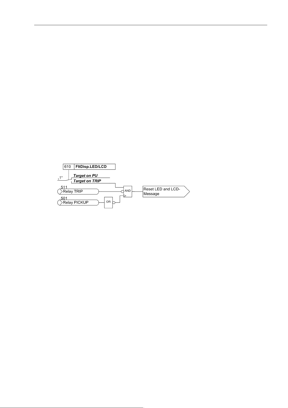
The following figure illustrates the creation of the reset command for stored messages. By the moment of the
device dropout, the presetting of the parameter610 FltDisp.LED/LCD decides, whether the new fault will be
stored or reset.
Functions
2.1 General
Figure 2-1 Creation of the reset command for the latched LED and LCD messages
Spontaneous Messages on the Display
You can determine whether or not the most important data of a fault event is displayed automatically after the
fault has occurred (see also Subsection "Fault Messages" in Section "Auxiliary Functions").
SIPROTEC, 7RW80, Manual
C53000-G1140-C233-1, Release date 10.2010
27

Functions
2.1 General
2.1.2.2 Setting Notes
Fault Display
A new pickup by a protection element generally turns off any previously lit LEDs so that only the latest fault is
displayed at any one time. It can be selected whether the stored LED displays and the spontaneous fault indications on the display appear upon the new pickup, or only after a new trip signal is issued. In order to select
the desired displaying mode, select the submenu Device in the SETTINGS menu. Under address 610
FltDisp.LED/LCD the two alternatives Target on PU and Target on TRIP ("No trip – no flag") can be
selected.
Use parameter 611 Spont. FltDisp. to specify whether or not a spontaneous fault message should appear
automatically on the display (YES) or not (NO).
Selection of Default Display
The start page of the default display appearing after startup of the device can be selected in the device data
via parameter 640 Start image DD. The pages available for each device version are listed in the Appendix
A.4.
2.1.2.3 Settings
Addr. Parameter Setting Options Default Setting Comments
610 FltDisp.LED/LCD Target on PU
Target on TRIP
611 Spont. FltDisp. YES
NO
640 Start image DD image 1
image 2
image 3
image 4
Target on PU Fault Display on LED / LCD
NO Spontaneous display of flt.annun-
ciations
image 1 Start image Default Display
2.1.2.4 Information List
No. Information Type of In-
formation
- >Light on SP >Back Light on
- Reset LED IntSP Reset LED
- DataStop IntSP Stop data transmission
- Test mode IntSP Test mode
- Feeder gnd IntSP Feeder GROUNDED
- Brk OPENED IntSP Breaker OPENED
- HWTestMod IntSP Hardware Test Mode
- SynchClock IntSP_Ev Clock Synchronization
- Distur.CFC OUT Disturbance CFC
1 Not configured SP No Function configured
2 Non Existent SP Function Not Available
3 >Time Synch SP_Ev >Synchronize Internal Real Time Clock
5 >Reset LED SP >Reset LED
Comments
28
C53000-G1140-C233-1, Release date 10.2010
SIPROTEC, 7RW80, Manual

Functions
2.1 General
No. Information Type of In-
Comments
formation
15 >Test mode SP >Test mode
16 >DataStop SP >Stop data transmission
51 Device OK OUT Device is Operational and Protecting
52 ProtActive IntSP At Least 1 Protection Funct. is Active
55 Reset Device OUT Reset Device
56 Initial Start OUT Initial Start of Device
67 Resume OUT Resume
68 Clock SyncError OUT Clock Synchronization Error
69 DayLightSavTime OUT Daylight Saving Time
70 Settings Calc. OUT Setting calculation is running
71 Settings Check OUT Settings Check
72 Level-2 change OUT Level-2 change
73 Local change OUT Local setting change
110 Event Lost OUT_Ev Event lost
113 Flag Lost OUT Flag Lost
125 Chatter ON OUT Chatter ON
140 Error Sum Alarm OUT Error with a summary alarm
160 Alarm Sum Event OUT Alarm Summary Event
177 Fail Battery OUT Failure: Battery empty
178 I/O-Board error OUT I/O-Board Error
181 Error A/D-conv. OUT Error: A/D converter
191 Error Offset OUT Error: Offset
193 Alarm NO calibr OUT Alarm: NO calibration data available
301 Pow.Sys.Flt. OUT Power System fault
302 Fault Event OUT Fault Event
303 sens Gnd flt OUT sensitive Ground fault
320 Warn Mem. Data OUT Warn: Limit of Memory Data exceeded
321 Warn Mem. Para. OUT Warn: Limit of Memory Parameter exceeded
322 Warn Mem. Oper. OUT Warn: Limit of Memory Operation exceeded
323 Warn Mem. New OUT Warn: Limit of Memory New exceeded
502 Relay Drop Out SP Relay Drop Out
510 Relay CLOSE SP General CLOSE of relay
545 PU Time VI Time from Pickup to drop out
546 TRIP Time VI Time from Pickup to TRIP
10080 Error Ext I/O OUT Error Extension I/O
10081 Error Ethernet OUT Error Ethernet
10083 Error Basic I/O OUT Error Basic I/O
SIPROTEC, 7RW80, Manual
C53000-G1140-C233-1, Release date 10.2010
29

Functions
2.1 General
2.1.3 Power System Data 1
2.1.3.1 Description
The device requires certain data regarding the network and substation so that it can adapt its functions to this
data depending on the application. This may be, for instance, nominal data of the substation and measuring
transformers, polarity and connection of the measured quantities, breaker properties (where applicable), etc.
There are also certain parameters that are common to all functions, i.e. not associated with a specific protection, control or monitoring function. The following section discusses this data.
2.1.3.2 Setting Notes
General
Some P.System Data 1 can be entered directly at the device. See section 2.14 for more information regarding this topic.
In DIGSI double-click Settings to open the corresponding dialog box. In doing so, a dialog box with tabs will
open under P.System Data 1 where individual parameters can be configured. The following descriptions
are therefore structured according to these tabs.
Nominal Frequency (Power System)
The nominal frequency of the system is set under the Address 214 Rated Frequency. The factory pre-setting
in accordance with the model need only be changed if the device will be employed for a purpose other than
that which was planned when ordering. In the US device versions (ordering data position 10= C), parameter
214 is preset to 60 Hz.
Voltage Connection (Power System)
Address 213 specifies how the voltage transformers are connected.
VT Connect. 3ph = Van, Vbn, Vcn means that the three phase voltages are wye connected, i.e. the three
phase-to-ground voltages are measured.
VT Connect. 3ph = Vab, Vbc, VGnd means that two phase-to-phase voltages (open delta voltage) and
the displacement voltage V
VT Connect. 3ph = Vab, Vbc means that two phase-to-phase voltages (open delta voltage) are connected.
The third voltage transformer of the device is not used.
VT Connect. 3ph = Vab, Vbc, Vx means that two phase-to-phase voltages (open delta voltage) are con-
nected. Furthermore, any third voltage V
tions. The transformer nominal voltages for V
VT Connect. 3ph = Vab, Vbc, VSyn means that two phase-to-phase voltages (open delta voltage) and
the reference voltage for V
device is used.
are connected.
GND
is connected that is used exclusively for the flexible protection func-
x
are set at address 232 and 233.
x
are connected. This setting is enabled if the synchronization function of the
SYN
30
VT Connect. 3ph = Vph-g, VSyn is used if the synchronization function of the device is used and only
phase-to-ground voltages are available for the protected object to be synchronized. One of these voltages is
connected to the first voltage transformer; the reference voltage V
is connected to the third voltage trans-
SYN
former.
The selection of the voltage transformer connection affects the operation of all device functions that require
voltage input.
C53000-G1140-C233-1, Release date 10.2010
SIPROTEC, 7RW80, Manual
 Loading...