

Page 1
Page 2

Page 3
___________________
___________________
___________________
___________________
SINAMICS
S120
Communication
Function Manual
Valid as of:
Firmware version 5.2
12/2018
6SL3097
Preface
Fundamental safety
instructions
1
General information
2
Communication according to
PROFIdrive
3
Communication via
PROFIBUS DP
4
Communication via
PROFINET IO
5
Communication via Modbus
TCP
6
Communication via
Ethernet/IP (EIP)
7
Communication via
SINAMICS Link
8
Appendix
A
-5BD00-0BP0
Page 4
Siemens AG
Division Digital Factory
Postfach 48 48
90026 NÜRNBERG
GERMANY
Document order number: 6SL3097-5BD00-0BP0
Ⓟ
Copyright © Siemens AG 2018.
All rights reserved
DANGER
indicates that death or severe personal injury will result if proper precautions are not taken.
WARNING
indicates that death or severe personal injury may result if proper precautions are not taken.
CAUTION
indicates that minor personal injury can result if proper precautions are not taken.
NOTICE
indicates that property damage can result if proper precautions are not taken.
WARNING
Siemens products may only be used for the applications described in the catalog and in the relevant technical
maintenance are required to ensure that the products operate safely and without any problems. The permissible
ambient conditions must be complied with. The information in the relevant documentation must be observed.
Legal information
Warning notice system
This manual contains notices you have to observe in order to ensure your personal safety, as well as to prevent
damage to property. The notices referring to your personal safety are highlighted in the manual by a safety alert
symbol, notices referring only to property damage have no safety alert symbol. These notices shown below are
graded according to the degree of danger.
If more than one degree of danger is present, the warning notice representing the highest degree of danger will
be used. A notice warning of injury to persons with a safety alert symbol may also include a warning relating to
property damage.
Qualified Personnel
The product/system described in this documentation may be operated only by personnel qualified for the specific
task in accordance with the relevant documentation, in particular its warning notices and safety instructions.
Qualified personnel are those who, based on their training and experience, are capable of identifying risks and
avoiding potential hazards when working with these products/systems.
Proper use of Siemens products
Note the following:
documentation. If products and components from other manufacturers are used, these must be recommended
or approved by Siemens. Proper transport, storage, installation, assembly, commissioning, operation and
Trademarks
All names identified by ® are registered trademarks of Siemens AG. The remaining trademarks in this publication
may be trademarks whose use by third parties for their own purposes could violate the rights of the owner.
Disclaimer of Liability
We have reviewed the contents of this publication to ensure consistency with the hardware and software
described. Since variance cannot be precluded entirely, we cannot guarantee full consistency. However, the
information in this publication is reviewed regularly and any necessary corrections are included in subsequent
editions.
11/2018 Subject to change
Page 5

Preface
SINAMICS documentation
The SINAMICS documentation is organized in the following categories:
● General documentation/catalogs
● User documentation
● Manufacturer/service documentation
Additional information
You can find information on the topics below at the following address
(https://support.industry.siemens.com/cs/de/en/view/108993276):
● Ordering documentation/overview of documentation
● Additional links to download documents
● Using documentation online (find and search in manuals/information)
Please send any questions about the technical documentation (e.g. suggestions for
improvement, corrections) to the following email address
(mailto:[email protected]).
Siemens MySupport/Documentation
At the following address (https://support.industry.siemens.com/My/ww/en/documentation),
you can find information on how to create your own individual documentation based on
Siemens' content, and adapt it for your own machine documentation.
Training
At the following address (http://www.siemens.com/sitrain), you can find information about
SITRAIN (Siemens training on products, systems and solutions for automation and drives).
FAQs
You can find Frequently Asked Questions in the Service&Support pages at Product Support
(https://support.industry.siemens.com/cs/de/en/ps/faq).
SINAMICS
Communication
Function Manual, 12/2018, 6SL3097-5BD00-0BP0
You can find information about SINAMICS at the following address
(http://www.siemens.com/sinamics).
3
Page 6

Preface
Usage phase
Document/tool
Orientation
SINAMICS S Sales Documentation
Usage phases and their documents/tools (as an example)
Planning/configuration
Deciding/ordering SINAMICS S120 catalogs
Installation/assembly
Commissioning
Usage/operation
Maintenance/servicing
References
• SIZER Engineering Tool
• Configuration Manuals, Motors
• SINAMICS S120 and SIMOTICS (Catalog D 21.4)
• SINAMICS Converters for Single-Axis Drives and SIMOTICS Motors (Cata-
log D 31)
• SINAMICS Converters for Single-Axis Drives – Built-In Units (D 31.1)
• SINAMICS Converters for Single-Axis Drives – Distributed Converters (D 31.2)
• SINUMERIK 840 Equipment for Machine Tools (Catalog NC 62)
• SINAMICS S120 Equipment Manual for Control Units and Additional System
Components
• SINAMICS S120 Equipment Manual for Booksize Power Units
• SINAMICS S120 Equipment Manual for Booksize Power Units C/D Type
• SINAMICS S120 Equipment Manual for Chassis Power Units
• SINAMICS S120 Equipment Manual for Chassis Power Units, Liquid-cooled
• SINAMICS S120 Equipment Manual water-cooled chassis power units for com-
mon cooling circuits
• SINAMICS S120 Equipment Manual for Chassis Power Units, Air-cooled
• SINAMICS S120 Equipment Manual for AC Drives
• SINAMICS S120 Equipment Manual Combi
• SINAMICS S120M Equipment Manual Distributed Drive Technology
• SINAMICS HLA System Manual Hydraulic Drives
• Startdrive Commissioning Tool
• SINAMICS S120 Getting Started
• SINAMICS S120 Commissioning Manual
• SINAMICS S120 Function Manual Drive Functions
• SINAMICS S120 Safety Integrated Function Manual
• SINAMICS S120 Function Manual Communication
• SINAMICS S120/S150 List Manual
• SINAMICS HLA System Manual Hydraulic Drives
• SINAMICS S120 Commissioning Manual
• SINAMICS S120/S150 List Manual
• SINAMICS HLA System Manual Hydraulic Drives
• SINAMICS S120 Commissioning Manual
• SINAMICS S120/S150 List Manual
• SINAMICS S120/S150 List Manual
Communication
4 Function Manual, 12/2018, 6SL3097-5BD00-0BP0
Page 7
Preface
Software
Manual
Alarms
Described in order of ascending numbers
SINAMICS S120/S150 List Manual
Sorted according to topic
Described in order of ascending numbers
Drive functions
SINAMICS S120 Function Manual Drive Functions
firmware V5.2)
Basic and Extended Functions
SINAMICS S120 Safety Integrated Function Manual
Basic Functions
SINAMICS S120 Function Manual Drive Functions
STARTER
SINAMICS S120 Commissioning Manual (up to firmware
V5.1 SP1)
Startdrive
V5.2)
Web server
SINAMICS S120 Function Manual Drive Functions
Hardware
Manual
Units, Air-cooled or Liquid-cooled
AC drive components
SINAMICS S120 Equipment Manual for AC Drives
S120 Combi components
SINAMICS S120 Equipment Manual Combi
V5.1 SP1)
V5.2)
Meaning of the LEDs
Equipment Manuals
High Frequency Drive components
SINAMICS S120 System Manual High Frequency Drives
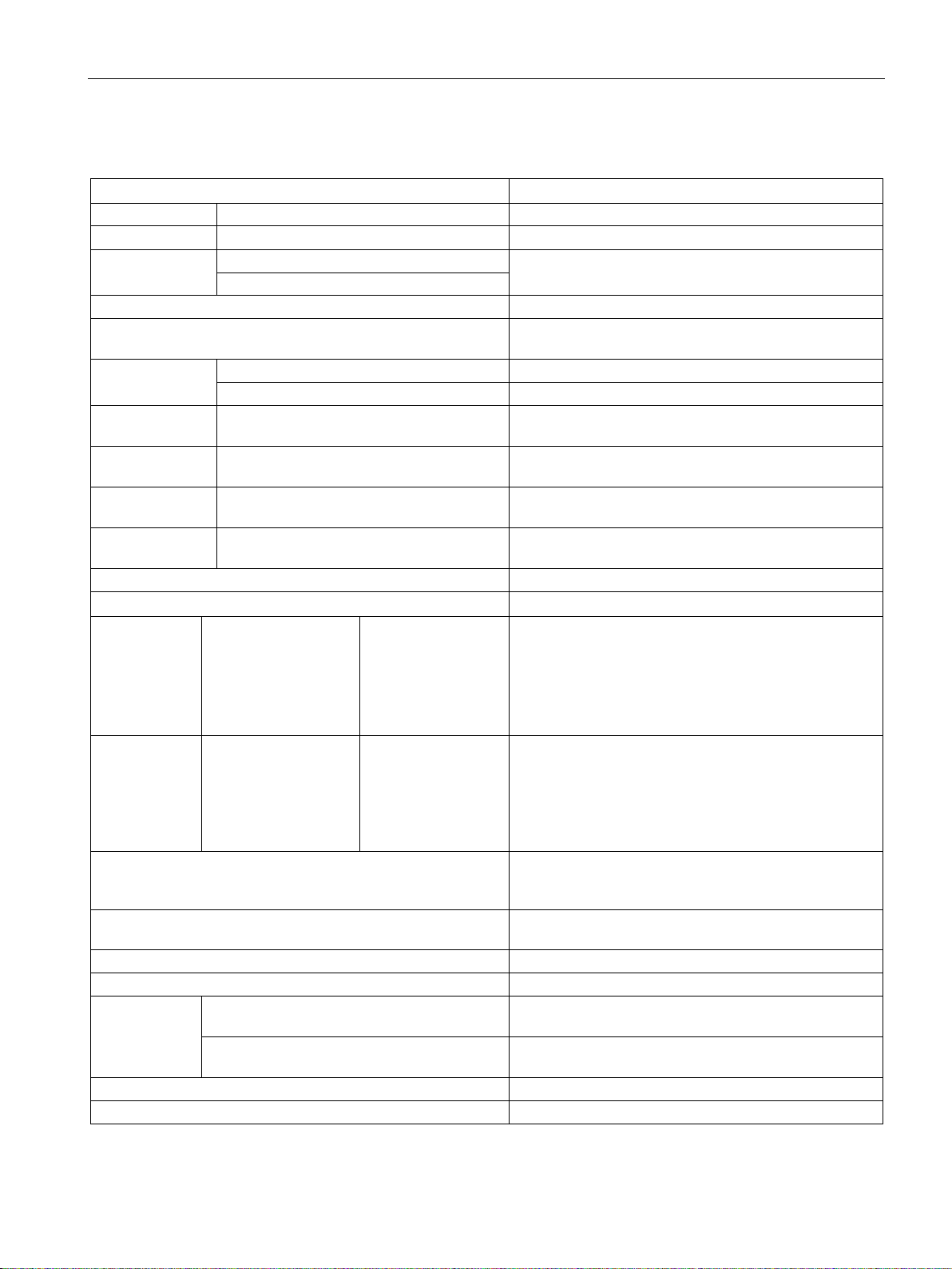
Where can the various topics be found?
Parameters Described in order of ascending numbers SINAMICS S120/S150 List Manual
Function block
diagrams
Communication topics SINAMICS S120 Function Manual Communication (from
Safety Integrated
SINAMICS S120/S150 List Manual
Commissioning Of a simple SINAMICS S120 drive with
Commissioning With STARTER
Commissioning Of a simple SINAMICS S120 drive with
Commissioning With Startdrive SINAMICS S120 Commissioning Manual (from firmware
Control Units And expansion com-
ponents:
• Control Units
• Option Boards
• Terminal Modules
Power units
booksize
Power units, booksize C/D type format SINAMICS S120 Equipment Manual for Booksize Power
Chassis power units SINAMICS S120 Equipment Manual for Chassis Power
• Line connection
• Line Modules
• Motor Modules
• HUB Modules
• VSM10
• Encoder system
connection
• DC link compo-
nents
• Braking resistors
• Control cabinet
design
Getting Started (up to Firmware V5.1 SP1)
Getting Started (from Firmware V5.2)
SINAMICS S120 Equipment Manual for Control Units
and Additional System Components
SINAMICS S120 Equipment Manual for Booksize
Power Units
Units
C/D Type
Diagnostics via
LEDs
Communication
Function Manual, 12/2018, 6SL3097-5BD00-0BP0
STARTER SINAMICS S120 Commissioning Manual (up to firmware
Startdrive SINAMICS S120 Commissioning Manual (from firmware
5
Page 8

Preface
Target group
This documentation is intended for machine manufacturers, commissioning engineers, and
service personnel who use the SINAMICS drive system.
Benefits
This manual provides all of the information, procedures and operator actions required for the
particular usage phase.
Standard scope
The scope of the functionality described in this document can differ from that of the drive
system that is actually supplied.
● Other functions not described in this documentation might be able to be executed in the
drive system. However, no claim can be made regarding the availability of these functions
when the equipment is first supplied or in the event of service.
● The documentation can also contain descriptions of functions that are not available in a
particular product version of the drive system. Please refer to the ordering documentation
only for the functionality of the supplied drive system.
● Extensions or changes made by the machine manufacturer must be documented by the
machine manufacturer.
For reasons of clarity, this documentation does not contain all of the detailed information on
all of the product types, and cannot take into consideration every conceivable type of
installation, operation and service/maintenance.
Technical Support
Country-specific telephone numbers for technical support are provided in the Internet at the
following address (https://support.industry.siemens.com/sc/ww/en/sc/2090) in the "Contact"
area.
Information about CANopen
Information about communication via CANopen is provided in the following Manual:
● SINAMICS S120 Commissioning Manual CANopen Interface
Compliance with the General Data Protection Regulation
Siemens respects the principles of data protection, in particular the data minimization rules
(privacy by design).
For this product, this means:
The product does not process neither store any person-related data, only technical function
data (e.g. time stamps). If the user links these data with other data (e.g. shift plans) or if he
stores person-related data on the same data medium (e.g. hard disk), thus personalizing
these data, he has to ensure compliance with the applicable data protection stipulations.
Communication
6 Function Manual, 12/2018, 6SL3097-5BD00-0BP0
Page 9

Preface
•
Fault 12345
•
Alarm 67890
•
Safety message
•
Adjustable parameter 918
•
Display parameter 1024
•
Adjustable parameter 1
•
Adjustable parameter 2098, index 1 bit 3
•
Adjustable parameter 99, indices 0 to 3
•
Display parameter 945, index 2 of drive object 3
•
Adjustable parameter 795, bit 4
Notation
The following notation and abbreviations are used in this documentation:
Notation for faults and alarms (examples):
F12345
A67890
C23456
Notation for parameters (examples):
p0918
r1024
p1070[1]
p2098[1].3
p0099[0...3]
r0945[2](3)
p0795.4
070, index 1
Communication
Function Manual, 12/2018, 6SL3097-5BD00-0BP0
7
Page 10

Preface
Communication
8 Function Manual, 12/2018, 6SL3097-5BD00-0BP0
Page 11

Table of contents
Preface ................................................................................................................................................... 3
1 Fundamental safety instructions ............................................................................................................ 13
1.1 General safety instructions ..................................................................................................... 13
1.2 Warranty and liability for application examples ...................................................................... 13
1.3 Industrial security .................................................................................................................... 14
2 General information .............................................................................................................................. 17
2.1 Field of application .................................................................................................................. 17
2.2 Platform Concept and Totally Integrated Automation ............................................................. 18
2.3 System overview ..................................................................................................................... 20
2.4 X127 LAN (Ethernet)............................................................................................................... 22
2.5 Communication services and used port numbers .................................................................. 23
2.6 Time synchronization between the control and converter ...................................................... 26
2.6.1 Setting SINAMICS time synchronization ................................................................................ 28
2.6.2 Set NTP time synchronization ................................................................................................ 29
2.6.3 Messages and parameters ..................................................................................................... 30
3 Communication according to PROFIdrive .............................................................................................. 31
3.1 PROFIdrive application classes .............................................................................................. 34
3.2 Cyclic communication ............................................................................................................. 37
3.2.1 Telegrams and process data .................................................................................................. 37
3.2.2 Information about control words and status words ................................................................. 41
3.2.3 Examples ................................................................................................................................ 42
3.2.4 Motion control with PROFIdrive .............................................................................................. 45
3.3 Parallel operation of communication interfaces ...................................................................... 48
3.4 Acyclic communication............................................................................................................ 51
3.4.1 General information about acyclic communication ................................................................. 51
3.4.2 Structure of requests and responses ...................................................................................... 53
3.4.3 Determining the drive object numbers .................................................................................... 59
3.4.4 Example 1: read parameters .................................................................................................. 60
3.4.5 Example 2: Writing parameters (multi-parameter request)..................................................... 62
3.5 Diagnostics channels .............................................................................................................. 66
3.5.1 PROFINET-based diagnostics ................................................................................................ 67
3.5.2 PROFIBUS-based diagnostics ............................................................................................... 70
3.5.2.1 Standard diagnostics .............................................................................................................. 71
3.5.2.2 Identifier-related diagnostics ................................................................................................... 71
3.5.2.3 Status messages/module status ............................................................................................. 72
3.5.2.4 Channel-related diagnostics ................................................................................................... 73
3.5.2.5 Data sets DS0/DS1 and diagnostics alarm............................................................................. 74
Communication
Function Manual, 12/2018, 6SL3097-5BD00-0BP0
9
Page 12

Table of contents
3.6 Configuring telegrams in Startdrive........................................................................................ 75
3.6.1 Displaying telegram configuration .......................................................................................... 75
3.6.2 Settings for SINAMICS S120, S150, G150, G130, MV ......................................................... 76
4 Communication via PROFIBUS DP ....................................................................................................... 79
4.1 General information about PROFIBUS .................................................................................. 79
4.1.1 General information about PROFIBUS for SINAMICS .......................................................... 79
4.1.2 Example: telegram structure for cyclic data transmission ..................................................... 82
4.2 Commissioning PROFIBUS ................................................................................................... 85
4.2.1 Setting the PROFIBUS interface ............................................................................................ 85
4.2.2 PROFIBUS interface in operation .......................................................................................... 88
4.2.3 Commissioning PROFIBUS ................................................................................................... 89
4.2.4 Diagnostics options ................................................................................................................ 90
4.2.5 SIMATIC HMI addressing ...................................................................................................... 90
4.2.6 Monitoring telegram failure .................................................................................................... 92
4.3 Motion Control with PROFIBUS ............................................................................................. 94
4.4 Slave-to-slave communication ............................................................................................... 98
4.4.1 Setpoint assignment in the subscriber ................................................................................. 100
4.4.2 Activating/parameterizing slave-to-slave communication .................................................... 100
4.4.3 Commissioning PROFIBUS slave-to-slave communication ................................................ 102
4.4.4 Diagnosing PROFIBUS slave-to-slave communication ....................................................... 108
4.5 Messages via diagnostics channels..................................................................................... 108
5 Communication via PROFINET IO ....................................................................................................... 111
5.1 General information about PROFINET IO ........................................................................... 111
5.1.1 Real-time (RT) and isochronous real-time (IRT) communication ........................................ 113
5.1.2 Addresses ............................................................................................................................ 114
5.1.3 Dynamic IP address assignment ......................................................................................... 116
5.1.4 DCP flashing ........................................................................................................................ 118
5.1.5 Data transfer ........................................................................................................................ 118
5.1.6 Communication channels for PROFINET ............................................................................ 120
5.1.7 References ........................................................................................................................... 121
5.1.8 Overview of important parameters ....................................................................................... 122
5.2 RT classes for PROFINET IO .............................................................................................. 124
5.3 PROFINET GSDML ............................................................................................................. 129
5.4 Motion Control with PROFINET ........................................................................................... 131
5.5 Communication with CBE20 ................................................................................................ 135
5.6 Communication via PROFINET Gate .................................................................................. 136
5.6.1 Functions supported by PN Gate ......................................................................................... 137
5.6.2 Preconditions for PN Gate ................................................................................................... 138
5.7 PROFINET with 2 controllers ............................................................................................... 139
5.7.1 Control Unit settings ............................................................................................................. 139
5.7.2 Configuring Shared Device .................................................................................................. 141
5.7.3 Overview of important parameters ....................................................................................... 150
5.8 PROFINET media redundancy ............................................................................................ 151
5.9 PROFINET system redundancy ........................................................................................... 152
Communication
10 Function Manual, 12/2018, 6SL3097-5BD00-0BP0
Page 13

Table of contents
5.9.1 Overview ............................................................................................................................... 152
5.9.2 Design, configuring and diagnostics ..................................................................................... 153
5.9.3 Messages and parameters ................................................................................................... 154
5.10 PROFIenergy ........................................................................................................................ 155
5.10.1 Tasks of PROFIenergy ......................................................................................................... 157
5.10.2 PROFIenergy commands ..................................................................................................... 158
5.10.3 PROFIenergy measured values ........................................................................................... 159
5.10.4 PROFIenergy energy-saving mode ...................................................................................... 160
5.10.5 PROFIenergy inhibit and pause time .................................................................................... 160
5.10.6 Function diagrams and parameters ...................................................................................... 161
5.11 Messages via diagnostics channels ..................................................................................... 161
5.12 Support of I&M data sets 1...4 .............................................................................................. 163
6 Communication via Modbus TCP ........................................................................................................ 165
6.1 Overview ............................................................................................................................... 165
6.2 Configuring Modbus TCP via interface X150 ....................................................................... 167
6.3 Configuring Modbus TCP via interface X1400 ..................................................................... 168
6.4 Mapping tables ...................................................................................................................... 169
6.5 Write and read access using function codes ........................................................................ 172
6.6 Communication via data set 47 ............................................................................................ 175
6.6.1 Communication details.......................................................................................................... 176
6.6.2 Examples: Read parameter .................................................................................................. 176
6.6.3 Examples: Write parameter .................................................................................................. 178
6.7 Communication procedure .................................................................................................... 180
6.8 Messages and parameters ................................................................................................... 181
7 Communication via Ethernet/IP (EIP) .................................................................................................. 183
7.1 Overview ............................................................................................................................... 183
7.2 Connecting the drive device to EIP ....................................................................................... 184
7.3 Requirements for communication ......................................................................................... 185
7.4 Configuring EIP via the onboard PROFINET X150 interface ............................................... 186
7.5 Configuring EIP via the X1400 interface at the CBE20 ........................................................ 187
7.6 Supported objects ................................................................................................................. 188
7.7 Integrating the drive device into the EIP network via DHCP ................................................ 200
7.8 Messages and parameters ................................................................................................... 201
8 Communication via SINAMICS Link .................................................................................................... 203
8.1 Basic principles of SINAMICS Link ....................................................................................... 203
8.2 Topology ............................................................................................................................... 205
8.3 Configuring and commissioning ............................................................................................ 207
8.4 Example ................................................................................................................................ 211
8.5 Communication failure when booting or in cyclic operation.................................................. 214
Communication
Function Manual, 12/2018, 6SL3097-5BD00-0BP0
11
Page 14

Table of contents
8.6 Examples: Transmission times for SINAMICS Link ............................................................. 214
8.7 Function diagrams and parameters ..................................................................................... 215
A Appendix ............................................................................................................................................. 217
A.1 List of abbreviations ............................................................................................................. 217
A.2 Documentation overview ...................................................................................................... 227
Index ................................................................................................................................................... 229
Communication
12 Function Manual, 12/2018, 6SL3097-5BD00-0BP0
Page 15
1
WARNING
Danger to life if the safety instructions and residual risks are not observed
WARNING
Malfunctions of the machine as a result of incorrect or changed parameter settings
1.1 General safety instructions
If the safety instructions and residual risks in the associated hardware documentation are
not observed, accidents involving severe injuries or death can occur.
• Observe the safety instructions given in the hardware documentation.
• Consider the residual risks for the risk evaluation.
As a result of incorrect or changed parameterization, machines can malfunction, which in
turn can lead to injuries or death.
• Protect the parameterization (parameter assignments) against unauthorized access.
• Handle possible malfunctions by taking suitable measures, e.g. emergency stop or
emergency off.
1.2 Warranty and liability for application examples
Application examples are not binding and do not claim to be complete regarding
configuration, equipment or any eventuality which may arise. Application examples do not
represent specific customer solutions, but are only intended to provide support for typical
tasks.
As the user you yourself are responsible for ensuring that the products described are
operated correctly. Application examples do not relieve you of your responsibility for safe
handling when using, installing, operating and maintaining the equipment.
Communication
Function Manual, 12/2018, 6SL3097-5BD00-0BP0
13
Page 16

Fundamental safety instructions
Note
Industrial security
Siemens provides products and solutions with industrial security functions that support the
secure operation of plants, systems, machines and net
In order to protect plants, systems, machines and networks against cyber threats, it is
necessary to implement
security concept. Siemens’ products and solutions constitute one ele
Customers are responsible for preventing unauthorized access to their plants, systems,
machines and networks. Such systems, machines and components should only be
connected to an enterprise network or the Internet if and to the exte
necessary and only when appropriate security measures (e.g. firewalls and/or network
segmentation) are in place.
For additional information on industrial security measures that may be implemented, please
visit:
Industrial security
Siemens’ products and solutions undergo continuous development to make them more
secure. Siemens strongly recommends that product updates are applied as soon as they are
available and that the latest product versions are used. Use of product versions that are no
longer supported, and failure to apply the latest updates may increase customer’s exposure
to cyber threats.
To stay informed about product upd
Feed at:
Industrial security (
1.3 Industrial security
1.3 Industrial security
works.
– and continuously maintain – a holistic, state-of-the-art industrial
ment of such a concept.
nt such a connection is
(http://www.siemens.com/industrialsecurity)
ates, subscribe to the Siemens Industrial Security RSS
http://www.siemens.com/industrialsecurity)
Further information is provided on the Internet:
Industrial Security Configuration Manual
(https://support.industry.siemens.com/cs/ww/en/view/108862708)
Communication
14 Function Manual, 12/2018, 6SL3097-5BD00-0BP0
Page 17
Fundamental safety instructions
WARNING
Unsafe operating states resulting from software manipulation
1.3 Industrial security
Software manipulations (e.g. viruses, trojans, malware or worms) can cause unsafe
operating states in your system that may lead to death, serious injury, and property
damage.
• Keep the software up to date.
• Incorporate the automation and drive components into a holistic, state-of-the-art
industrial security concept for the installation or machine.
• Make sure that you include all installed products into the holistic industrial security
concept.
• Protect files stored on exchangeable storage media from malicious software by with
suitable protection measures, e.g. virus scanners.
• Protect the drive against unauthorized changes by activating the "know-how protection"
drive function.
Communication
Function Manual, 12/2018, 6SL3097-5BD00-0BP0
15
Page 18

Fundamental safety instructions
1.3 Industrial security
Communication
16 Function Manual, 12/2018, 6SL3097-5BD00-0BP0
Page 19

2
2.1 Field of application
SINAMICS is the family of drives from Siemens designed for machine and plant engineering
applications. SINAMICS offers solutions for all drive tasks:
● Simple pump and fan applications in the process industry
● Complex single drives in centrifuges, presses, extruders, elevators, as well as conveyor
and transport systems
● Drive line-ups in textile, plastic film, and paper machines as well as in rolling mill plants
● High-precision servo drives in the manufacture of wind turbines
● Highly dynamic servo drives for machine tools, as well as packaging and printing
machines
Figure 2-1 SINAMICS applications
Communication
Function Manual, 12/2018, 6SL3097-5BD00-0BP0
17
Page 20

General information
2.2 Platform Concept and Totally Integrated Automation
Depending on the application, the SINAMICS range offers the ideal variant for any drive
task.
● SINAMICS S handles complex drive tasks with synchronous motors and induction motors
and fulfills stringent requirements regarding:
– the dynamic performance and accuracy
– the integration of extensive technological functions in the drive control system
● SINAMICS G is designed for standard applications with induction motors. These
applications have less stringent requirements regarding the dynamic performance of the
motor speed.
● SINAMICS V is designed to address applications where basic drive functions are
available quickly and at a favorable cost - and which are easy to handle.
2.2 Platform Concept and Totally Integrated Automation
All SINAMICS versions are based on a platform concept. Joint hardware and software
components, as well as standardized tools for design, configuration, and commissioning
tasks ensure high-level integration across all components. SINAMICS handles a wide variety
of drive tasks with no system gaps. The different SINAMICS versions can be easily
combined with each other.
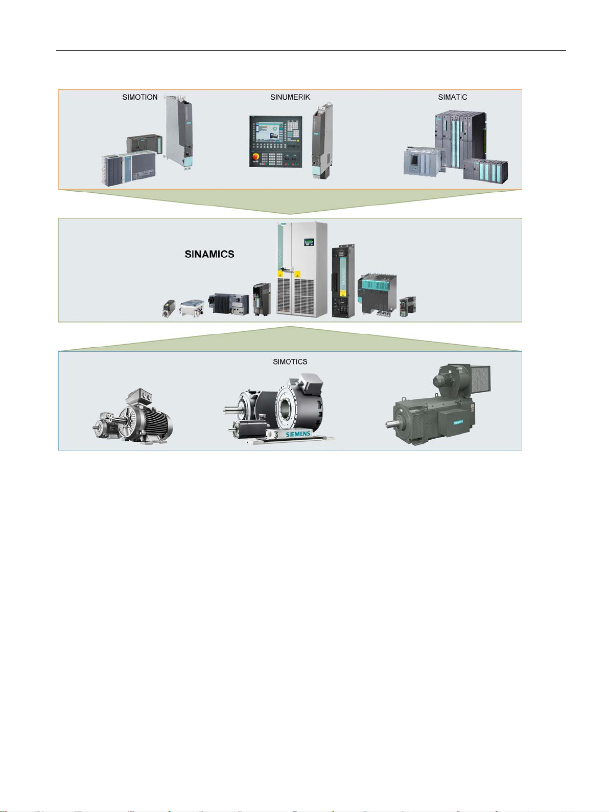
Totally Integrated Automation (TIA) with SINAMICS S120
Apart from SIMATIC, SIMOTION and SINUMERIK, SINAMICS is one of the core
components of TIA. It is thus possible to parameterize, program and commission all
components in the automation system via the Startdrive commissioning tool using a
standardized engineering platform and without any system transitions (seamless
engineering). The system-wide data management functions ensure consistent data and
simplify archiving of the entire plant project.
From V14, the Startdrive commissioning tool is an integral element of the TIA platform.
SINAMICS S120 supports communication via PROFINET and PROFIBUS DP.
Communication via PROFINET
This Ethernet-based bus enables control data to be exchanged at high speed via
PROFINET IO with IRT or RT and makes SINAMICS S120 a suitable choice for integration
in high-performance multi-axis applications. At the same time, PROFINET also uses
standard IT mechanisms (TCP/IP) to transport information, e.g. operating and diagnostic
data, to higher-level systems. This makes it easy to integrate into an IT corporate network.
Communication via PROFIBUS DP
This bus provides a high-performance, system-wide and integrated communication network
which links all automation components of the automation solution:
● HMI (operator control and monitoring)
● Control
● Drives and I/O
Communication
18 Function Manual, 12/2018, 6SL3097-5BD00-0BP0
Page 21
General information
2.2 Platform Concept and Totally Integrated Automation
Figure 2-2 SINAMICS as part of the Siemens modular automation system
Communication
Function Manual, 12/2018, 6SL3097-5BD00-0BP0
19
Page 22
General information
2.3 System overview
2.3 System overview
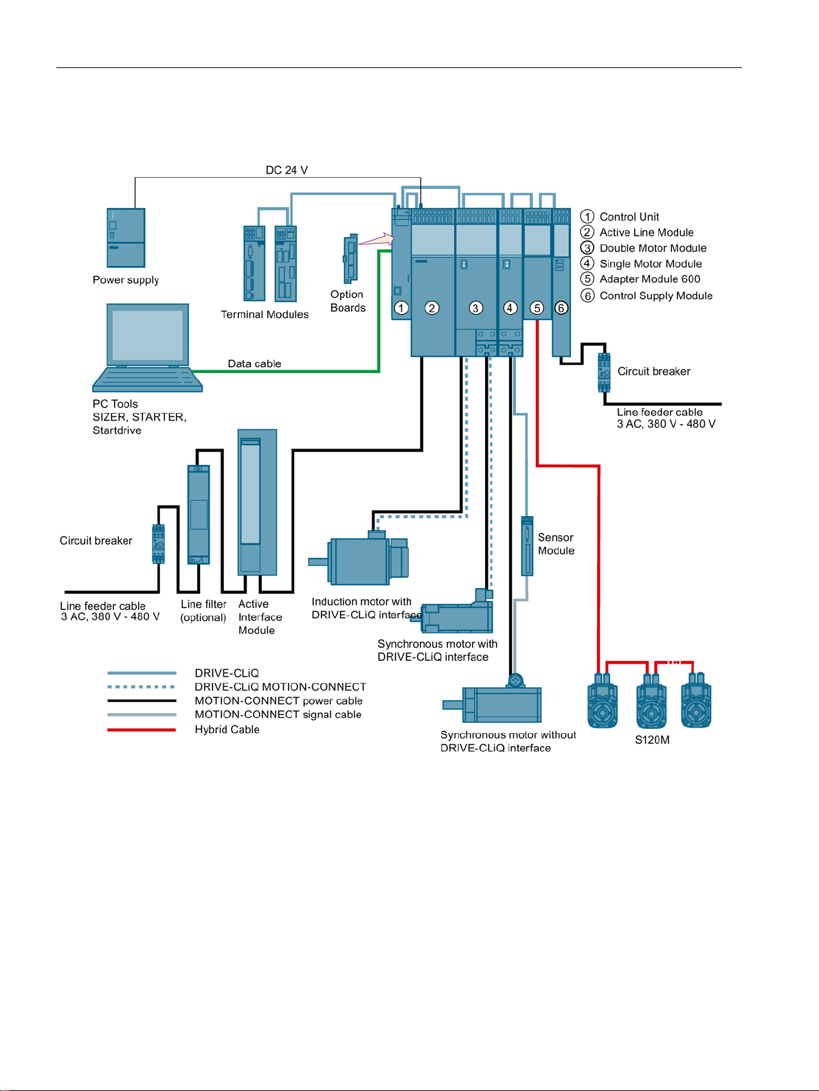
Figure 2-3 System overview, SINAMICS S120 with distributed servo drive technology S120M
Modular system for sophisticated drive tasks
SINAMICS S120 solves complex drive tasks for a wide range of industrial applications and
is, therefore, designed as a modular system. You can choose from many different
harmonized components and functions to create a solution that best meets your
requirements. SIZER, a high-performance engineering tool, makes it easier to select and
determine the optimum drive configuration.
Communication
20 Function Manual, 12/2018, 6SL3097-5BD00-0BP0
Page 23

General information
2.3 System overview
SINAMICS S120 is supplemented by a wide range of motors. SINAMICS S120 optimally
supports:
● SINAMICS S120M
● Synchronous and induction motors
● Linear and torque motors
System architecture with a central Control Unit
On the SINAMICS S120, the drive intelligence is combined with closed-loop control functions
into Control Units. These units are capable of controlling drives in the vector, servo and V/f
control modes. They also perform the speed and torque control functions plus other
intelligent drive functions for all axes on the drive. Cross-axis couplings can be established
within a component and easily configured in the Startdrive commissioning tool using a
mouse.
Functions for higher efficiency
● Basic functions: Speed control, torque control, positioning functions
● Intelligent starting functions for independent restart after power supply interruption
● BICO technology with interconnection of drive-related I/Os for easy adaptation of the
drive system to its operating environment
● Integrated safety functions for rational implementation of safety concepts
● Regulated infeed/regenerative feedback functions for preventing undesirable reactions on
the supply, allowing recovery of braking energy and ensuring greater stability against line
fluctuations.
DRIVE-CLiQ – the digital interface between SINAMICS components
Most of the SINAMICS S120 components, including the motors and encoders, are
connected to each other via the common DRIVE-CLiQ serial interface. The standardized
cables and connectors reduce the variety of different parts and cut storage costs. Encoder
evaluations for converting standard encoder signals to DRIVE-CLiQ are available for thirdparty motors or retrofit applications.
Electronic rating plates in all components
An important digital linkage element of the SINAMICS S120 drive system are the electronic
type plates integrated in every component. They allow all drive components to be detected
automatically via a DRIVE-CLiQ link. As a result, data does not have to be entered manually
during commissioning or component replacement – helping to ensure that drives are
commissioned more reliably.
The rating plate contains all the relevant technical data about that particular component. For
motors, these are the parameters of the electrical equivalent circuit diagram and key values
of the integrated motor encoder, for example.
In addition to the technical data, the type plate includes logistical data (manufacturer ID,
article number and ID). Since this data can be called up electronically on site or remotely, all
the components used in a machine can always be individually identified, which helps simplify
servicing.
Communication
Function Manual, 12/2018, 6SL3097-5BD00-0BP0
21
Page 24

General information
Note
Use
Ethernet interface X127 is intended for commissioning and diagnostics, which means that it
must always be accessible (e.g. for service).
Further, the following restrictions apply to
•
•
2.4 X127 LAN (Ethernet)
2.4 X127 LAN (Ethernet)
X127:
Only local access is possible
No networking - or only local networking in a closed and locked electrical cabinet
permissible
If it is necessary to remotely access the electrical cabinet, then additional security measures
must be applied so that misuse through sabotage, unqualified data manipulation and
intercepting confidential data is completely ruled out (also see "Industrial security
(Page 14)").
Communication
22 Function Manual, 12/2018, 6SL3097-5BD00-0BP0
Page 25

General information
Protocol
Port number
(2) Link layer
(4) Transport layer
Function
Description
PROFINET protocols
Unique Identifier
01-80-C2-00-00-0E
Identifier
2.5 Communication services and used port numbers
2.5 Communication services and used port numbers
SINAMICS converters support the communication protocols listed in the following table. The
address parameters, the relevant communication layer, as well as the communication role
and the communication direction are decisive for each protocol. You require this information
to match the security measures for the protection of the automation system to the used
protocols (e.g. firewall). The security measures are restricted to Ethernet and PROFINET
networks.
The following table shows the various layers and protocols that are used.
Layers and protocols
DCP
Discovery and Con-
figuration Protocol
LLDP
Link Layer Discovery
Protocol
MRP
Media Redundancy
Protocol
Not relevant (2) Ethernet II and
IEEE 802.1Q and
Ethertype 0x8892
(PROFINET)
Not relevant (2) Ethernet II and
IEEE 802.1Q and
Ethertype 0x88CC
(PROFINET)
Not relevant (2) Ethernet II and
IEEE 802.1Q and
Ethertype 0x88E3
(PROFINET)
Accessible nodes,
PROFINET Dis-
covery and configuration
PROFINET Link
Layer Discovery
protocol
PROFINET medium redundancy
DCP is used by PROFINET to
determine PROFINET devices
and to make basic settings.
DCP uses the special multicast MAC address:
xx-xx-xx-01-0E-CF,
xx-xx-xx = Organizationally
LLDP is used by PROFINET
to determine and manage
neighborhood relationships
between PROFINET devices.
LLDP uses the special multicast MAC address:
MRP enables the control of
redundant routes through a
ring topology.
MRP uses the special multicast MAC address:
xx-xx-xx-01-15-4E,
xx-xx-xx = Organizationally
Unique
Communication
Function Manual, 12/2018, 6SL3097-5BD00-0BP0
23
Page 26

General information
Protocol
Port number
(2) Link layer
(4) Transport layer
Function
Description
Unique Identifier
IO devices via Ethernet.
Connection-oriented communication protocols
ter p8908.
DHCP mode.
and can be deactivated.
and is always required.
2.5 Communication services and used port numbers
PTCP
Precision Transpar-
ent Clock Protocol
PROFINET IO data Not relevant (2) Ethernet II and
PROFINET Context
Manager
FTP
File Transfer Protocol
Not relevant (2) Ethernet II and
IEEE 802.1Q and
Ethertype 0x8892
(PROFINET)
IEEE 802.1Q and
Ethertype 0x8892
(PROFINET)
34964 (4) UDP PROFINET con-
21 (4) TCP Server/
PROFINET
send clock and
time synchronisation, based on
IEEE 1588
PROFINET Cyclic
IO data transfer
nection less RPC
incoming
PTC enables a time delay
measurement
between RJ45 ports and
therefore the send cycle synchronization and time synchronization.
PTCP uses the special multicast MAC address:
xx-xx-xx-01-0E-CF,
xx-xx-xx = Organizationally
The PROFINET IO telegrams
are used to cyclically transfer
IO data between the
PROFINET IO controller and
The PROFINET context manager provides an endpoint
mapper in order to establish
an application relationship
(PROFINET AR).
FTP can be used for the first
commissioning.
FTP can be activated/deactivated using parame-
DHCP
Dynamic Host Con-
figuration Protocol
http
Hypertext Transfer
Protocol
ISO on TCP
(according to
RFC 1006)
Communication
68 (4) UDP Dynamic Host
80 (4) TCP Hypertext transfer
102 (4) TCP ISO-on-TCP proto-
24 Function Manual, 12/2018, 6SL3097-5BD00-0BP0
Configuration Protocol
protocol
col
Is used to query an IP address.
Is closed when delivered, and
is opened when selecting the
http is used for the communication with the CU-internal
web server.
Is open in the delivery state
ISO on TCP (according to
RFC 1006) is used for the
message-oriented data exchange to a remote CPU,
WinAC, or devices of other
suppliers.
Communication with ES, HMI,
etc.
Is open in the delivery state
Page 27

General information
Protocol
Port number
(2) Link layer
(4) Transport layer
Function
Description
SNMP enables the reading out
and is always required.
and can be deactivated.
project data.
not specify the local port.
EtherNet/IP protocols
EtherNet/IP.
EtherNet/IP.
Modbus TCP protocols (server)
Modbus TCP.
2.5 Communication services and used port numbers
SNMP
Simple Network
Management Protocol
https
Secure Hypertext
Transfer Protocol
Internal
protocol
Reserved 49152...65535 (4) TCP
Explicit messaging 44818 (4) TCP
161 (4) UDP Simple network
443 (4) TCP Secure Hypertext
5188 (4) TCP Server/
(4) UDP
(4) UDP
management protocol
transfer protocol
incoming
- Dynamic port area that is used
- Is used for parameter access,
and setting of network management data (SNMP managed Objects) by the SNMP
manager.
Is open in the delivery state
https is used for the communication with the CU-internal
web server via Transport Layer Security(TLS).
Is open in the delivery state
Communication with commissioning tools for downloading
for the active connection endpoint if the application does
etc.
Is closed when delivered, and
is opened when selecting
Implicit messaging 2222 (4) UDP - Is used for exchanging I/O
Request & Response 502 (4) TCP - Is used for exchanging data
data.
Is closed when delivered, and
is opened when selecting
packages.
Is closed when delivered, and
is opened when selecting
Communication
Function Manual, 12/2018, 6SL3097-5BD00-0BP0
25
Page 28

General information
Synchronization type
Accuracy
Basic synchronization
approx. 100ms
Synchronization using ping compensation for isochronous communication
approx. 1 ms
Synchronization with the Network Time Protocol via a PROFINET connection
approx. 10 ms
2.6 Time synchronization between the control and converter
2.6 Time synchronization between the control and converter
In the factory setting, SINAMICS S120 drives use an operating hours counter. Based on the
operating hours, SINAMICS S120 saves alarms and warnings that occur. Using this method,
it is not possible to have a comparable timestamp between various converters.
In order to obtain a comparable timestamp between several converters, you must change
over the operating hours counting to time in the UTC format and synchronize with the time
master (control system).
This means that the events of all bus nodes, which are synchronized with the control system
time, can be referenced with one another.
Benefits: Improved diagnostic options by having a comparable time stamp of the bus nodes
involved.
Converters provide the following options to synchronize the time:
Synchronization using ping compensation for non-isochronous communication approx. 10 ms
Principle of operation of time synchronization
Basic synchronization
The control system transfers the time to the converter at time intervals that you specify in the
control system. Transfer is realized acyclically in the UTC format. The converter accepts this
time as soon as transfer has been completed without correcting the transfer duration. The
converter logs alarms and warnings based on this time.
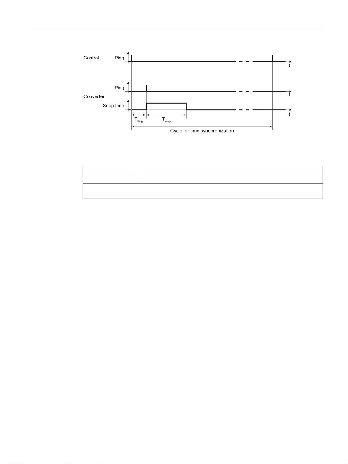
Time synchronization with ping compensation
At intervals that you specify in the control system, the control system sends a ping (a positive
signal edge) cyclically to the converter. Simultaneously, in acyclic operation, the device
sends the time in the UTC format in what is known as "snap".
As soon as the ping has been received in the drive, a timer starts which measures the time
until the snap has been completely transferred. The drive accepts the time that the snap
transfers. It then corrects it by the time that has expired between receiving the ping and the
complete transfer of the snap.
If the snap has not been transferred within 5 s after receiving the ping, then this
synchronization cycle is not used.
Communication
26 Function Manual, 12/2018, 6SL3097-5BD00-0BP0
Page 29
General information
Communication
Description
sampling time (p2048).
2.6 Time synchronization between the control and converter
Figure 2-4 Ping snap
Differences for isochronous and non-isochronous communication:
Isochronous The ping compensation value is determined in the converter.
not isochronous You can influence the accuracy of the ping compensation using the PZD
Time synchronization via Network Time Protocol (NTP)
Through NTP, all computers worldwide can synchronize their time. An inverter configured as
an NTP client synchronizes the time via a PROFINET connection to an NTP server (a time
source).
As NTP server, the following constellations are possible:
● Local NTP server that receives the time via GPS or DCF77 (e.g. SICLOCK).
● Control as NTP server if the plant network is divided into a control level and a field level.
Communication
Function Manual, 12/2018, 6SL3097-5BD00-0BP0
27
Page 30

General information
2.6 Time synchronization between the control and converter
2.6.1 Setting SINAMICS time synchronization
Setting time synchronization
1. Using p3100, changeover the time format from operating hours into the UTC format (see
"Changing the time format").
2. Set the synchronization technique:
– Basic synchronization (p3103 = 2)
– Time synchronization with ping compensation (p3103 = 0)
3. Using p3104, set the ping source:
– If you are working with one of the telegrams 390, 391 or 392, then the source of the
ping (p3104) is internally connected with bit 1 of the CU control word
(DO1:CU_STW.1). In this case, parameter p3104 is blocked.
– If you are using a free telegram (999), interconnect the ping source (p3104) via BICO
in the control word.
– If you are working with CANopen, interconnect a free bit in the CANopen control word
with p3104 via a BICO connection.
Result:
After time synchronization, the current time is obtained from the time transferred by the time
master plus the necessary delay time associated with the transfer (ping-snap time).
The actual UTC time is displayed in the drive system using r3102.
At certain intervals, synchronization (according to the same technique) is repeated
(depending on the setting in the time master).
If a previously defined tolerance window is exceeded, then alarm A01099 is output. Define
the tolerance window for time synchronization using p3109. If alarm A01099 occurs, then
generally the synchronization interval is too long.
In this case, reduce the synchronization interval in your control system.
Changing the time format
The time format is entered via parameter p3100. This parameter cannot be changed online
To change the value, proceed as follows:
1. Connect Startdrive ONLINE with the converter.
2. Carry out an upload using the "Load from device" function.
3. In Startdrive, exit the ONLINE mode.
4. Offline, make the setting p3100 = 1.
5. Reactivate the ONLINE mode.
6. Carry out a parameter download ("Load to device").
7. Save the settings in a non-volatile fashion on the memory card of the drive.
You have now changed over the converter time format to the UTC format.
Application example
You can find an application example for SINAMICS time synchronization in the SIEMENS
"Industry Online Support":
Example: Specific SINAMICS time synchronization
(https://support.industry.siemens.com/cs/de/en/view/88231134)
Communication
28 Function Manual, 12/2018, 6SL3097-5BD00-0BP0
Page 31

General information
2.6 Time synchronization between the control and converter
2.6.2 Set NTP time synchronization
Setting time synchronization with NTP
1. Using p3100, changeover the time format from operating hours into the UTC format (see
"Changing the time format").
2. Set the synchronization technique NTP (p3103 = 4).
3. Set the IP address of the NTP server used (p3105[0...3]).
– Special case: To use a PROFINET controller as NTP server, set p3105[0...3] = 0.
4. Set the local time zone (p3106).
Result:
After successful NTP time synchronization, the NTP time is converted to the already existing
UTC time.
If a previously defined tolerance window is exceeded, then alarm A01099 is output. The
tolerance window for time synchronization is defined using p3109. If alarm A01099 occurs,
then generally the synchronization interval is too long.
The converter outputs alarm A01097 if it does not reach the set NTP server within 10
minutes.
Changing the time format
The time format is entered via parameter p3100. This parameter cannot be changed online
To change the value, proceed as follows:
1. Connect Startdrive ONLINE with the converter.
2. Carry out an upload using the "Load from device" function.
3. In Startdrive, exit the ONLINE mode.
4. Offline, make the setting p3100 = 1.
5. Reactivate the ONLINE mode.
6. Carry out a parameter download ("Load to device").
7. Save the settings in a non-volatile fashion on the memory card of the drive.
You have now changed over the converter time format to UTC format.
Application example
You can find the following application example in the SIEMENS "Industry Online Support":
Example: Converter as NTP client
(https://support.industry.siemens.com/cs/ww/en/view/82203451)
Communication
Function Manual, 12/2018, 6SL3097-5BD00-0BP0
29
Page 32

General information
•
UTC synchronization tolerance violated
•
NTP server cannot be reached
•
IF1 PROFIdrive PZD sampling time
•
RTC time stam
•
Set UTC time
•
Display UTC time
•
UTC synchronization technique
•
BI: UTC PING synchronization
•
NTP server IP address
•
NTP time zone
•
UTC synchronization time out of tolerance
•
UTC synchronization deviation
•
UTC synchronization tolerance
•
BI: Suppress automatic acknowledgment
2.6 Time synchronization between the control and converter
2.6.3 Messages and parameters
Faults and alarms (see SINAMICS S120/S150 List Manual)
A01099
A01097 (N)
Overview of important parameters (see SINAMICS S120/S150 List Manual)
p2048
p3100
p3101[0...1]
r3102[0...1]
p3103
p3104
p3105[0...3]
p3106
r3107[0...3]
r3108[0...1]
p3109
p3116
p mode
Communication
30 Function Manual, 12/2018, 6SL3097-5BD00-0BP0
Page 33

3
Note
PROFIdrive for drive technology is standardized
•
•
PROFIdrive
PROFIBUS DP
PROFINET IO
Example
automation system)
Note
Consistent naming conventions
For reasons of consistency, the terms "device", "controller", and "supervisor" are used below.
The terms "slave" and "master" are only applied in the PROFIBUS chapter and are used
there still.
PROFIdrive is the PROFIBUS and PROFINET profile for drive technology with a wide range
of applications in production and process automation systems.
PROFIdrive is independent of the bus system used (PROFIBUS, PROFINET).
and described in the following document:
PROFIdrive – Profile Drive Technology,
PROFIBUS User Organization e. V.
Haid-und-Neu-Straße 7, D-76131 Karlsruhe,
Internet: (http://www.profibus.com)
IEC 61800-7
PROFIdrive device classes
Table 3- 1 PROFIdrive device classes
Peripheral device (P device) DP slave IO Device Drive unit, Control Unit
CU320-2
Motion controller (higherlevel controller or host of the
Supervisor (engineering
station)
Class 1 DP master IO Controller Higher-level control,
SIMATIC S7 and SIMOTION
Class 2 DP master IO Supervisor Programming devices, hu-
man machine interfaces
Communication
Function Manual, 12/2018, 6SL3097-5BD00-0BP0
31
Page 34
Communication according to PROFIdrive
Properties
Controller
Supervisor
Drive unit
As bus node
Active
Passive
request
Controller
strictions
permitted
Controller, Supervisor and drive unit
Table 3- 2 Properties of the Controller, Supervisor and drive units
Send messages Permitted without external
Receive messages Possible without any re-
Communication types
4 communication types are defined in the PROFIdrive profile:
● Cyclic data exchange via a cyclic data channel
Motion control systems require cyclically updated data in operation for open-loop and
closed-loop control tasks. This data must be sent to the drive units in the form of
setpoints or transmitted from the drive units in the form of actual values, via the
communications system. Transmission of this data is usually time-critical.
● Acyclic data exchange via an acyclic data channel
The PROFIdrive profile also provides an acyclic parameter channel to exchange
parameters between the controller – or the supervisor and drive units. Access to this data
is not time-critical.
● Alarm channel
Alarms are output on an event-driven basis, and show the occurrence and expiry of error
states.
● Isochronous mode
– Cyclic data exchange in a fixed time grid
Only possible on request by the
Only receive and acknowledge
– The controller and device are synchronized
Communication
32 Function Manual, 12/2018, 6SL3097-5BD00-0BP0
Page 35

Communication according to PROFIdrive
IF1
IF2
telegram
Free telegram x x
Isochronous mode x x
Ethernet/IP
Cyclic operation x x
PROFIsafe x x
Note
For additional information on the IF1 and IF2 interfaces, s
communication interfaces
Interface IF1 and IF2
The CU320-2 Control Unit can communicate via two different interfaces (IF1 and IF2).
You can assign both interfaces to the following physical interfaces (p8839):
● (1) Onboard X126 PROFIBUS / X150 PROFINET
● (2) Communication Board X1400
Table 3- 3 Properties of IF1 and IF2
PROFIdrive and SIEMENS
Drive object types All All
Can be used for PROFINET IO
SINAMICS Link
x -
PROFIBUS DP
PN Gate
Ethernet/IP
(Page 48)" in this manual.
Connecting a PG/PC with the Startdrive commissioning tool
PROFINET IO
PROFIBUS DP
CANopen
SINAMICS Link
PN Gate
ee chapter "Parallel operation of
The following connection options are available for Startdrive for commissioning a Control
Unit with a PG/PC using a commissioning tool.
● PROFINET
● Ethernet
See also
Industrial security (Page 14)
Communication
Function Manual, 12/2018, 6SL3097-5BD00-0BP0
33
Page 36

Communication according to PROFIdrive
3.1 PROFIdrive application classes
3.1 PROFIdrive application classes
There are different application classes for PROFIdrive according to the scope and type of the
application processes. PROFIdrive features a total of 6 application classes, the 3 most
important are compared here.
● Class 1 (AK1):
The drive is controlled using a speed setpoint via PROFIBUS/PROFINET. In this case,
speed control is fully handled in the drive.
Typical application examples include simple frequency converters for controlling pumps
and fans.
● Class 3 (AK3):
In addition to the speed control, the drive also includes a positioning control, which
means that it operates as an autonomous single-axis positioning drive while the higherlevel technological processes are performed in the control system. Positioning requests
are transferred to the drive controller via PROFINET (or PROFIBUS) and started.
● Class 4 (AK4):
This PROFIdrive application class defines a speed setpoint interface, where the speed
control is realized in the drive and the closed-loop position control in the control system,
such as is required for robotics and machine tool applications with coordinated motion
sequences on multiple drives.
Motion control is primarily implemented using a central numerical controller (NC). The
position control loop is closed via the bus, i.e. the communication between the controller
and the drive must be isochronous.
Communication
34 Function Manual, 12/2018, 6SL3097-5BD00-0BP0
Page 37

Communication according to PROFIdrive
Telegram
(p0922 = x)
Description
Class 1
Class 3
Class 4
1
Speed setpoint, 16-bit
x - -
3
Speed setpoint, 32-bit with 1 position encoder
x - x
vo Control
Servo Control
7
Basic positioner with selection of the traversing block
- x -
9
Basic positioner with direct setpoint input (MDI)
- x -
20
16-bit speed setpoint for VIK-Namur
x - -
81
Standard encoder
- - -
82
Standard encoder with speed actual value 16 bit
- - -
83
Standard encoder with speed actual value 32 bit
- - -
tion
tion
and Dynamic Servo Control
and Dynamic Servo Control
Basic positioner with direct setpoint input (MDI), override, position
actual value and speed actual value
DSC and additional actual values
DSC, additional actual values and 2 external encoders
(encoder 1)
ers (encoder 1 and encoder 2)
ers (encoder 1 and encoder 2), 4 trace signals
encoders (encoder 2 and encoder 3), 4 trace signals
3.1 PROFIdrive application classes
Selection of telegrams depending on the PROFIdrive application class
The following Table provides an overview of which telegram can be used reach which
PROFIdrive application class:
Table 3- 4 Selection of telegrams depending on the PROFIdrive application class
2 Speed setpoint, 32-bit x - -
4 Speed setpoint, 32-bit with 2 position encoders x - x
5 Speed setpoint, 32 bit with 1 position encoder and Dynamic Ser-
- - x
6 Speed setpoint, 32 bit with 2 position encoders and Dynamic
102 Speed setpoint, 32 bit with 1 position encoder and torque reduc-
103 Speed setpoint, 32 bit with 2 position encoders and torque reduc-
105 Speed setpoint, 32 bit with 1 position encoder, torque reduction
106 Speed setpoint, 32 bit with 2 position encoders, torque reduction
110 Basic positioner with direct setpoint input (MDI), override and
position actual value
111
116 32-bit speed setpoint with 2 position encoders, torque reduction,
- - x
x - x
x - x
- - x
- - x
- x -
- x -
- - x
118 32-bit speed setpoint with 2 position encoders, torque reduction,
125 Dynamic Servo Control with torque precontrol, 1 position encoder
126 Dynamic Servo Control with torque precontrol, 2 position encod-
136 Dynamic Servo Control with torque precontrol, 2 position encod-
138 Dynamic Servo Control with torque precontrol, 2 external position
Communication
Function Manual, 12/2018, 6SL3097-5BD00-0BP0
- - x
- - x
- - x
- - x
- - x
35
Page 38

Communication according to PROFIdrive
Telegram
(p0922 = x)
Description
Class 1
Class 3
Class 4
values
and encoder 3), additional actual values, adaptation parameters
values, adaptation parameters
tional signals
220
Speed setpoint, 32 bit, metal industry
x - -
352
16-bit speed setpoint for PCS7
x - -
370
Infeed - -
-
371
Infeed, metal industry
- - -
DO 8 … DO 15
… DO 15 and 6 probes
… DO 16, 8 probes and analog input
DO 8 … DO 16
… DO 16 and 16 probes
700
Supplementary PZD-0/3
- - -
701
Supplementary PZD-2/5
- - -
750
Supplementary PZD-3/1
- - -
999
Free interconnection and length
x x x
3.1 PROFIdrive application classes
139 Speed/position control with Dynamic Servo Control and torque
precontrol, 1 position encoder, clamping status, additional actual
146 Closed-loop speed/position control with Dynamic Servo Control
and torque precontrol, 2 position encoders (encoder 1 and encoder 2), additional actual values, adaptation parameters
148 Closed-loop speed/position control with Dynamic Servo Control
and torque precontrol, 2 external position encoders (encoder 2
149 Speed/position control with Dynamic Servo Control and torque
precontrol, 1 position encoder, clamping status, additional actual
166 Hydraulic axis (HLA) with two encoder channels and HLA addi-
390 Control Unit with digital inputs DI 0 … DI 15 and digital outputs
391 Control Unit with digital inputs DI 0 … DI 15, DO 8 … DO 15 and
2 probes
392 Control Unit with digital inputs DI 0 … DI 15, digital outputs DO 8
- - x
- - x
- - x
- - x
- - -
- - -
- - -
- - -
393 Control Unit with digital inputs DI 0 … DI 22, digital outputs DO 8
394 Control Unit with digital inputs DI 0 … DI 22 and digital outputs
395 Control Unit with digital inputs DI 0 … DI 22, digital outputs DO 8
Dynamic Servo Control (DSC)
The PROFIdrive profile contains the "Dynamic Servo Control" control concept. This requires
PROFIdrive application class 4 and transfers not only the speed setpoint, but also the KPC
position controller gain factor and the XERR system deviation. With the aid of this data, the
position controller can be calculated in the drive. The position setpoint interpolation is still
performed in the controller. This can be used to significantly increase the dynamic
stability/stiffness of the position control loop in PROFIdrive application class 4.
- - -
- - -
- - -
Communication
36 Function Manual, 12/2018, 6SL3097-5BD00-0BP0
Page 39

Communication according to PROFIdrive
3.2 Cyclic communication
3.2 Cyclic communication
Cyclic communication is used to exchange time-critical process data (e.g. setpoints and
actual values).
3.2.1 Telegrams and process data
The process data (PZD) that is to be transferred is defined through the configuration of the
drive unit (Control Unit). From the perspective of the drive unit, the received process data
represents the receive words and the process data to be sent the send words.
PROFIdrive telegrams
● Standard telegrams
The standard telegrams are structured in accordance with the PROFIdrive profile. The
drive-internal process data links are set up automatically in accordance with the set
telegram number.
The SINAMICS S120/S150 List Manual contains the standard telegrams in the following
function diagrams:
– 2415 PROFIdrive - Standard telegrams and process data 1
– 2416 PROFIdrive - Standard telegrams and process data 2
● Manufacturer-specific telegrams
The manufacturer-specific telegrams are structured in accordance with internal company
specifications. The drive-internal process data links are set up automatically in
accordance with the set telegram number.
The SINAMICS S120/S150 List Manual contains the manufacturer-specific telegrams
(SIEMENS telegrams) in the following function diagrams:
– 2419 PROFIdrive - Manufacturer-specific telegrams and process data 1
– 2420 PROFIdrive - Manufacturer-specific telegrams and process data 2
– 2421 PROFIdrive - Manufacturer-specific telegrams and process data 3
– 2422 PROFIdrive - Manufacturer-specific telegrams and process data 4
Communication
Function Manual, 12/2018, 6SL3097-5BD00-0BP0
37
Page 40

Communication according to PROFIdrive
SERVO, TM41
VECTOR
CU_S
A_INF, B_INF,
S_INF
TB30, TM31,
TM15DI_DO,
TM120,
TM150
ENCODER
Receive process data
nector output
or output
15
er
Send process data
nector input
10]
or input
11]
verter
3.2 Cyclic communication
● Supplementary telegrams
The SINAMICS S120/S150 List Manual contains supplementary telegrams in the
following function diagrams:
– 2423 PROFIdrive - Manufacturer-specific/free telegrams and process data
● Free telegrams (p0922 = 999)
The SINAMICS S120/S150 List Manual contains free telegrams in the following function
diagrams:
– 2468 PROFIdrive – IF1 receive telegram, free interconnection via BICO (p0922 = 999)
– 2470 PROFIdrive – IF1 send telegram, free interconnection via BICO (p0922 = 999)
The receive and send data can be freely connected using BICO technology.
DWORD con-
WORD connect-
Binector output r2090.0 ... 15
Free connectorbinector convert-
DWORD con-
WORD connect-
Free binectorconnector con-
r2060[0 ... 18] r2060[0 ... 30] - - - r2060[0 ... 2]
r2050[0 ... 19] r2050[0 ... 31] r2050[0 ... 19] r2050[0 ... 9] r2050[0 ... 4] r2050[0 ... 3]
r2091.0 ... 15
r2092.0 ... 15
r2093.0 ... 15
p2099[0 ... 1] / r2094.0 ... 15, r2095.0 ... 15
p2061[0 ... 26] p2061[0 ... 30] - - - p2061[0 ...
p2051[0 ... 27] p2051[0 ... 31] p2051[0 ... 24] p2051[0 ... 9] p2051[0 ... 4] p2051[0 ...
p2080[0 ... 15], p2081[0 ... 15], p2082[0 ... 15], p2083[0 ... 15], p2084[0...15] / r2089[0 ... 4]
r2090.0 ... 15
r2091.0 ... 15
r2090.0 ...
15
r2091.0 ...
15
r2092.0 ...
15
r2093.0 ...
Communication
38 Function Manual, 12/2018, 6SL3097-5BD00-0BP0
Page 41
Communication according to PROFIdrive
3.2 Cyclic communication
Telegram interconnections
● The telegram interconnection is made automatically and blocked.
Telegrams 20, 111, 220, 352 are exceptions. There, in addition to the fixed
interconnections, selected process data (PZD) can be interconnected as required in the
send/receive telegram.
● When you change p0922 ≠ 999 to p0922 = 999, the previous telegram interconnection is
retained. You can now change this telegram interconnection.
● If p0922 = 999, a telegram can be selected in p2079. A telegram interconnection is
automatically made and blocked. The telegram can also be extended.
This is an easy method for creating extended telegram interconnections on the basis of
existing telegrams.
The telegram structure
● Parameter p0978 contains the drive objects that use a cyclic PZD exchange. All drive
objects after the first zero do not participate in the cyclic exchange.
● If the value 255 is written to p0978, this drive object is visible to the PROFIdrive controller
and empty (without actual process data exchange). This permits cyclic communication of
a PROFIdrive controller in the following cases:
– with unchanged configuration to drive units that have a different number of drive
objects.
– with deactivated drive objects, without having to change the project
● One PZD = one word.
● Physical word and double word values are inserted in the telegram as referenced
variables.
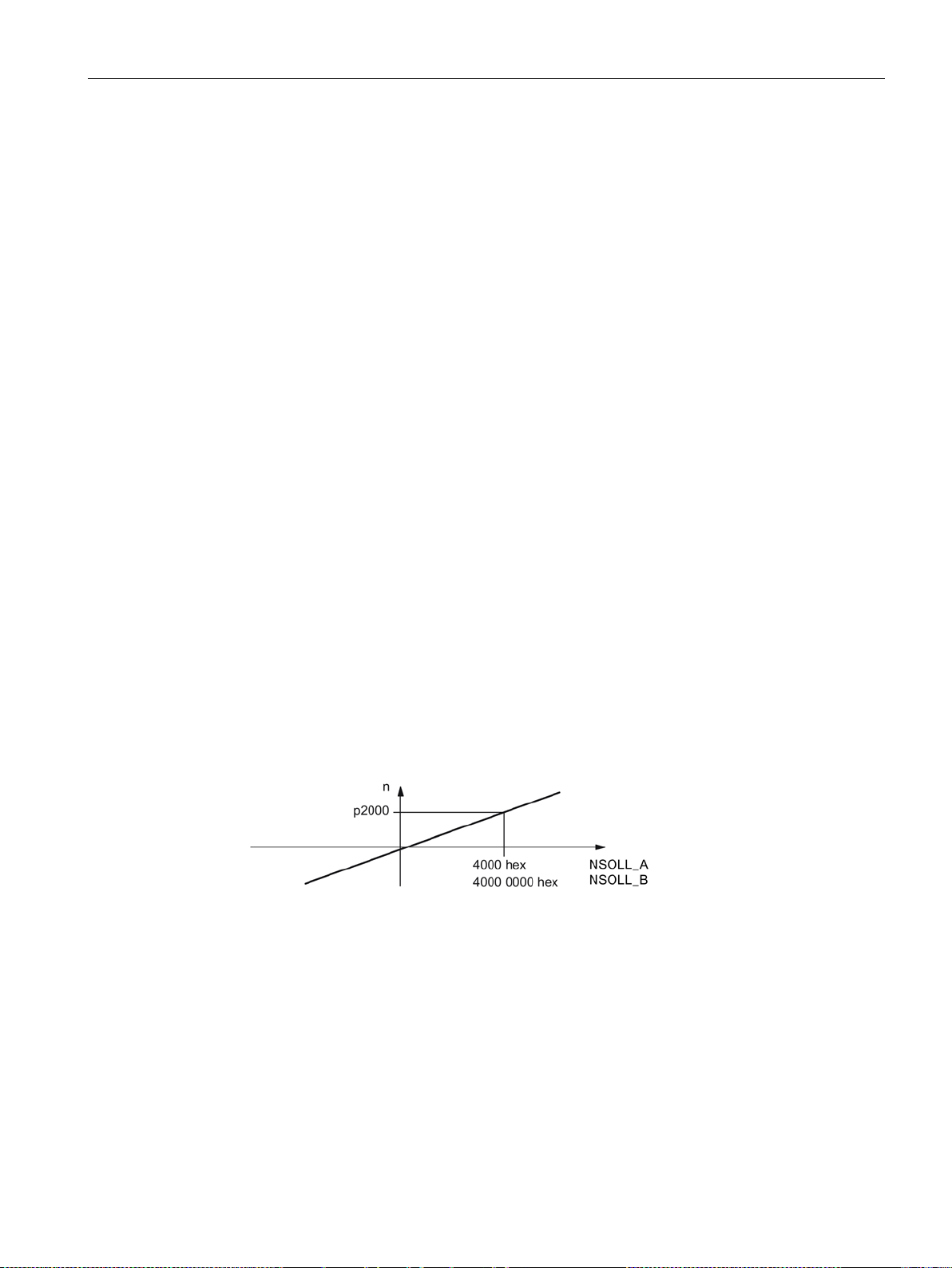
● p200x apply as reference variables (telegram contents = 4000 hex or 4000 0000 hex in
the case of double words if the input variable has the value p200x).
Figure 3-1 Normalization of speed
You can find the detailed structure of the telegrams in the SINAMICS S120/S150 List Manual
in the associated function diagrams.
Communication
Function Manual, 12/2018, 6SL3097-5BD00-0BP0
39
Page 42

Communication according to PROFIdrive
Drive object
Telegrams (p0922)
Function diagrams
A_INF
370, 371, 999
2421, 2423
S_INF
370, 371, 999
2421, 2423
SERVO (EPOS)
7, 9, 110, 111, 999
2415, 2423
SERVO (position control)
139, 149, 999
2420, 2423
2421, 2423
2423
ENC
81, 82, 83, 999
2416, 2423
TM15DI_DO
No predefined telegram.
-
2423
TM31
No predefined telegram.
-
TM41
3, 999
2415, 2423
TM120
No predefined telegram.
-
TM150
No predefined telegram.
-
TB30
No predefined telegram.
-
CU_S
390, 391, 392, 393, 394, 395, 999
2422, 2423
Drive objects
Maximum number of PZD
Send
Receive
A_INF
10
10
B_INF
10
10
SERVO
28
20
VECTOR
32
32
ENC
12
4
TM15DI_DO
5
5
TM31
5
5
TM41
28
20
TM120
5
5
TM150
5
5
TB30
5 5 CU
25
20
3.2 Cyclic communication
Which drive objects support which telegrams?
B_INF 370, 371, 999 2421, 2423
SERVO 1, 2, 3, 4, 5, 6, 102, 103, 105, 106, 116, 118, 125, 126,
136, 138, 139, 146, 148, 149, 220, 999
VECTOR 1, 2, 3, 4, 20, 220, 352, 999 2415, 2416,
VECTOR (EPOS) 7, 9, 110, 111, 999 2415, 2419,
HLA 166, 999 2415, 2420,
2415, 2419,
2420, 2423
Depending on the drive object, different process data (PZD) can be sent and received:
S_INF 10 10
Communication
40 Function Manual, 12/2018, 6SL3097-5BD00-0BP0
Page 43

Communication according to PROFIdrive
•
PROFIdrive
•
PROFIdrive
•
PROFIdrive
•
PROFIdrive
3.2 Cyclic communication
Interface Mode
Interface Mode is used for displaying the assignment of the control and status words in line
with other drive systems and standardized interfaces.
Interface Mode cannot be set by p2038, but rather by setting the telegrams in p0922:
● When standard telegram 20 is set, the "VIK-NAMUR" Interface Mode is permanently
specified (p2038 = 2). This relationship cannot be changed.
● When telegrams 102, 103, 105, 106, 116, 118, 125, 126, 136, 138, 139, 146, 148, 149
and 166 are set, the "SIMODRIVE 611 universal" Interface Mode is permanently specified
(p2038 = 1). This relationship cannot be changed.
● When all other telegrams are set, the "SINAMICS" Interface Mode is permanently
specified (p2038 = 0). This relationship cannot be changed.
3.2.2 Information about control words and status words
Overview of control words and setpoints
A detailed overview of the control words and setpoints is contained in the SINAMICS
S120/S150 List Manual in the following function diagrams:
2439
2440
- PZD receive signals, profile-specific interconnection
- PZD receive signals, manufacturer-specific interconnection
Overview of status words and actual values
A detailed overview of the status words and actual values is contained in the SINAMICS
S120/S150 List Manual in the following function diagrams:
2449
2450
- PZD send signals, profile-specific interconnection
- PZD send signals, manufacturer-specific interconnection
Communication
Function Manual, 12/2018, 6SL3097-5BD00-0BP0
41
Page 44
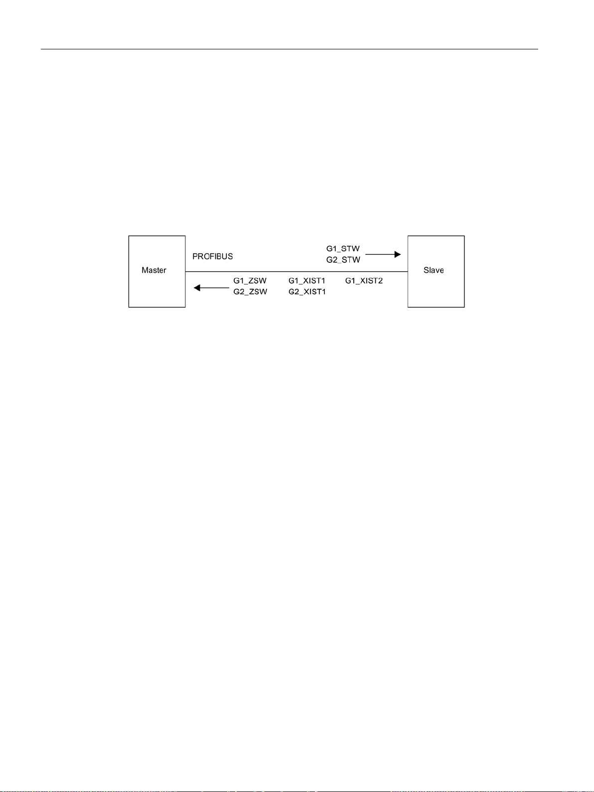
Communication according to PROFIdrive
3.2 Cyclic communication
3.2.3 Examples
Based on the PROFIdrive communication of the encoder interface, the following application
examples show:
● The chronological sequence of the communication
● The chronological changes to the control and status words
● The mutual dependencies of these changes
Example: Encoder interface
Figure 3-2 Example of encoder interface (encoder 1: Two actual values, encoder 2: One actual
value)
Example: Find reference mark
Assumptions for the example:
● Distance-coded reference mark
● Two reference marks (function 1 / function 2)
● Position control with encoder 1
Communication
42 Function Manual, 12/2018, 6SL3097-5BD00-0BP0
Page 45
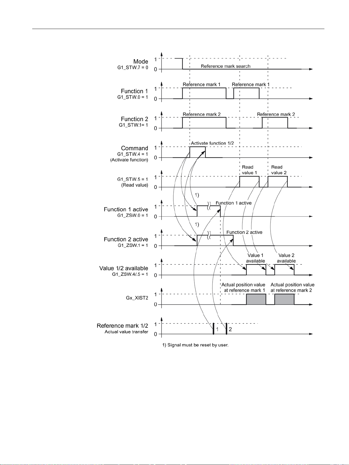
Communication according to PROFIdrive
3.2 Cyclic communication
Figure 3-3 Sequence chart for "Find reference mark"
Communication
Function Manual, 12/2018, 6SL3097-5BD00-0BP0
43
Page 46
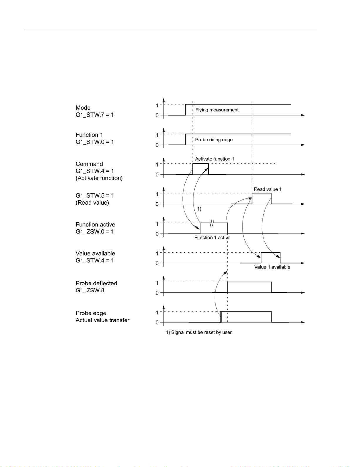
Communication according to PROFIdrive
3.2 Cyclic communication
Example: Flying measurement
Assumptions for the example:
● Measuring probe with rising edge (function 1)
● Position control with encoder 1
Figure 3-4 Sequence chart for "Flying measurement"
Communication
44 Function Manual, 12/2018, 6SL3097-5BD00-0BP0
Page 47

Communication according to PROFIdrive
Note
The isochronous drive coupling is defined in the following documentation:
PROFIdrive Profile Drive Technology
PROFIBUS User Organization e.
Haid
Internet: (
3.2 Cyclic communication
3.2.4 Motion control with PROFIdrive
An isochronous drive coupling can be established between the control and device using the
"Motion control with PROFIdrive" function.
V.
-und-Neu-Straße 7, D-76131 Karlsruhe,
http://www.profibus.com)
Properties
● No additional parameters need to be entered in addition to the bus configuration in order
to activate this function, the master and slave must only be preset for this function
(PROFIBUS).
● The controller-side default setting is made via the hardware configuration, e.g. HW Config
with SIMATIC S7. The device-side default setting is made using the parameterization
telegram when the bus ramps up.
● Fixed sampling times are used for all data communication.
● The Global Control (GC) clock information on PROFIBUS is sent before the beginning of
each cycle.
● The cycle length depends on the bus configuration. When the cycle is selected, the bus
configuration tool (e.g. HW Config) supports:
– Large number of drives per device/drive unit → longer cycle
– Large number of devices/ drive units → longer cycle
● A sign-of-life counter is used to monitor user data transfer and clock pulse failures.
Communication
Function Manual, 12/2018, 6SL3097-5BD00-0BP0
45
Page 48
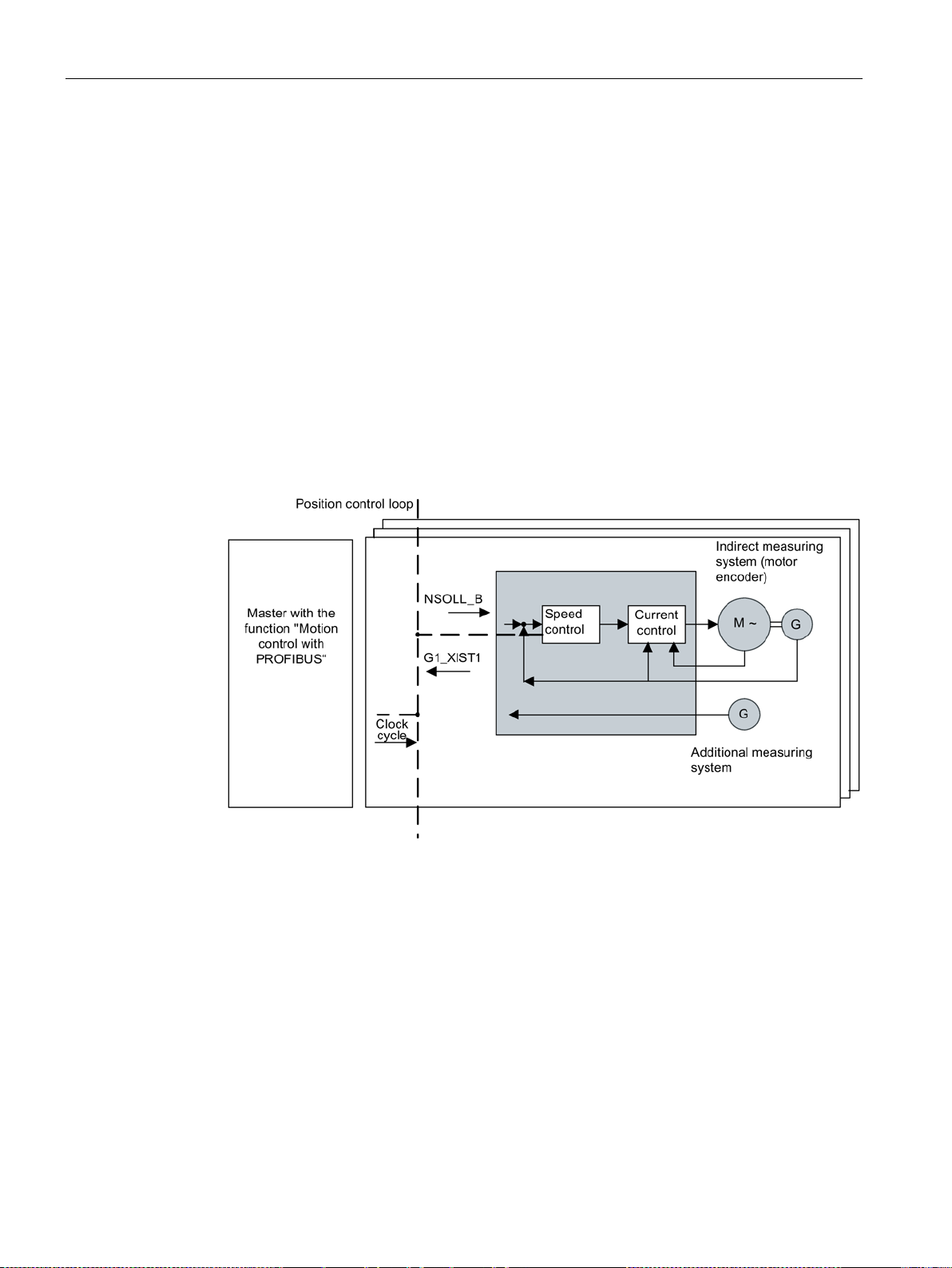
Communication according to PROFIdrive
3.2 Cyclic communication
Overview of closed-loop control
● Position actual value sensing in the device is alternatively realized using an:
– Indirect measuring system (motor encoder)
– Additional direct measuring system
● The encoder interface must be configured in the process data.
● The control loop is closed via PROFIBUS.
● The position controller is located in the controller.
● The current and speed control and actual value sensing (encoder interface) are located in
the device.
● The position controller cycle is transferred via the fieldbus to the devices.
● The slaves synchronize their speed and/or current controller sampling time with the
position controller clock cycle of the controller.
● The speed setpoint is specified by the controller.
Figure 3-5 Overview of "Motion Control with PROFIBUS" (example: controller and 3 devices)
Structure of the data cycle
The data cycle comprises the following elements:
● Global control telegram (PROFIBUS only)
● Cyclic part - setpoints and actual values
Communication
46 Function Manual, 12/2018, 6SL3097-5BD00-0BP0
Page 49
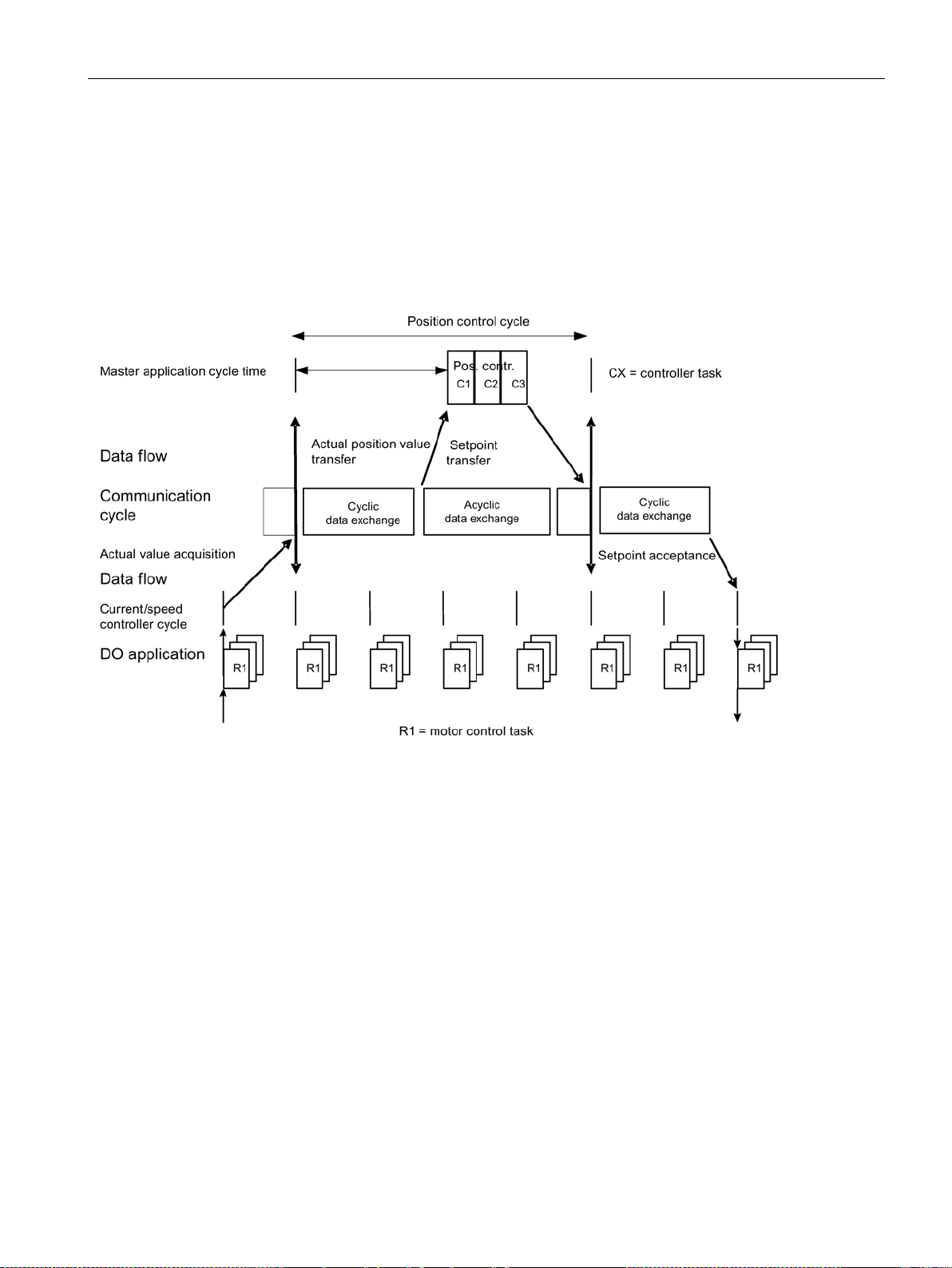
Communication according to PROFIdrive
3.2 Cyclic communication
● Acyclic part - parameters and diagnostic data
● Reserve (PROFIBUS only)
– Token passing (Token Holding Time, TTH)
– For searching for a new node in the drive line-up (GAP)
– Waiting time until start of the next cycle
Figure 3-6 Isochronous drive coupling / motion control with PROFIdrive
Communication
Function Manual, 12/2018, 6SL3097-5BD00-0BP0
47
Page 50

Communication according to PROFIdrive
Feature
IF1
IF2
Setpoint (BICO signal source)
r2050, r2060
r8850, r8860
3.3 Parallel operation of communication interfaces
3.3 Parallel operation of communication interfaces
The two cyclic interfaces for the setpoints and actual values differ by the parameter ranges
used (BICO technology etc.) and the functions that can be used. The interfaces are
designated as cyclic interface 1 (IF1) and cyclic interface 2 (IF2).
Cyclic process data (setpoints / actual values) are processed using interfaces IF1 and IF2.
The following interfaces are used:
● Onboard interfaces of the Control Unit for PROFIBUS DP or PROFINET.
● An optional interface (COMM BOARD) for PROFINET (CBE20) or CANopen (CBC10) for
insertion in the Control Unit.
Parameter p8839 is used to set the parallel use of the Control Unit onboard interfaces and
COMM - BOARD in the SINAMICS system. The functionality is assigned to interfaces IF1
and IF2 using indices.
For example, the following applications are possible:
● PROFIBUS DP for control and PROFINET to acquire
actual values / measured values of the drive
● PROFIBUS DP for control and PROFINET for engineering only
● Mixed mode with two masters (the first for logic and coordination and the second for
technology)
● SINAMICS Link via IF2 (CBE20); standard telegrams and PROFIsafe via IF1
● Operation of redundant communication interfaces
Assignment of communication interfaces to cyclic interfaces
With the factory setting p8839 = 99, the communication interfaces are permanently assigned
one of the cyclic interfaces (IF1, IF2), depending on the communication system, e.g.
PROFIBUS DP, PROFINET or CANopen.
The assignment to the cyclic interfaces can essentially be freely defined by user
parameterization for the parallel operation of the communication interfaces.
Properties of the cyclic interfaces IF1 and IF2
Table 3- 5 Properties of the cyclic interfaces IF1 and IF2
Actual value (BICO signal sink) p2051, p2061 p8851, p8861
Communication
48 Function Manual, 12/2018, 6SL3097-5BD00-0BP0
Page 51

Communication according to PROFIdrive
Plugged hardware interface
IF1
IF2
(PROFIBUS, PROFINET or USS)
Unit onboard USS
interface)
PROFINET
PROFINET
CAN option CBC10
Control Unit onboard
COMM BOARD CAN
Note
Parallel operation of PROFIBUS and PROFINET
Either the isochronous mode or the PROFIsafe functionality can be assigned to an interface
via p8815 (IF1 or IF2).
Example:
•
•
Additional parameter assignment options a
CBE20 is inserted in the CU320
•
•
3.3 Parallel operation of communication interfaces
Table 3- 6 Implicit assignment of hardware to the cyclic interfaces for p8839[0] = p8839[1] = 99
No option, only use Control Unit onboard interface
CU320-2 DP with CBE20 (optional PROFINET
interface)
CU320-2 PN with CBE20 (optional PROFINET
Control Unit onboard --
COMM BOARD Control Unit onboard
PROFIBUS or Control
Control Unit onboard
COMM BOARD
Parameter p8839[0,1] is used to set the parallel operation of the hardware interfaces and the
assignment to the cyclic interfaces IF1 and IF2 for the Control Unit drive object.
The sequence of objects is in line with p0978 (list of drive objects) for both interfaces.
The factory setting of p8839[0,1] = 99 enables the implicit assignment (see table above).
An alarm is generated in case of invalid or inconsistent parameterization of the assignment.
p8815[0] = 1: IF1 supports the isochronous mode.
p8815[1] = 2: IF2 supports PROFIsafe.
re possible if additionally the PROFINET module
-2 DP:
p8839[0] = 1 and p8839[1] = 2: PROFIBUS isochronous, PROFINET cyclic
p8839[0] = 2 and p8839[1] = 1: PROFINET isochronous, PROFIBUS cyclic
Communication
Function Manual, 12/2018, 6SL3097-5BD00-0BP0
49
Page 52

Communication according to PROFIdrive
Note
Using the HW Config configuration tool, a PROFIBUS slave / PROFINET device with two
interfaces cannot be sh
appears twice in the project or in two projects, although physically it is just one device.
p8839
PZD Interface hardware assignment
2.
Values:
0: Inactive
1: Control Unit onboard
2: COMM BOARD
99: Automatic
3.3 Parallel operation of communication interfaces
Parameters for IF2
The following parameters are available in order to tune the IF2 for a PROFIBUS or
PROFINET interface:
Parameter
● Receive and send process data:
r8850, p8851, r8853, r8860, p8861, r8863
1)
● Diagnostic parameters:
r8874, r8875, r8876
1)
● Binector-connector converters:
p8880, p8881, p8882, p8883, p8884, r8889
1)
● Connector-binector converters:
r8894, r8895, p8898, p8899
1)
Meaning of 88xx is identical to 20xx (for IF1)
1)
own. In parallel operation, this is the reason that SINAMICS drive
Description: Assigning the hardware for cyclic communication via PZD interface 1 and interface
For p8839, the following rules apply:
● The setting of p8839 applies for all drive objects of a Control Unit (device parameter).
● For the setting p8839[0] = 99 and p8839[1] = 99 (automatic assignment, factory setting),
the hardware used is automatically assigned to interfaces IF1 and IF2. Both indices must
be selected so that the automatic assignment is activated. If both indices are not
selected, then an alarm is output and the setting p8839[x] = 99 is treated just like
'inactive'.
● An alarm is issued if the same hardware (Control Unit onboard or COMM BOARD) is
selected in p8839[0] and p8839[1]. The following then applies: The setting of p8839[0] is
valid, and the setting of p8839[1] is treated like 'inactive'.
● If the CAN board (CBC10) is used, the entry of p8839[0] = 2 is not permissible (no
assignment of the CAN board to IF1). An alarm is then issued.
● If p8839[x] is set to 2, and the COMM BOARD is missing or defective, then the
corresponding interface is not supplied from the Control Unit onboard interface. Message
A08550 is output instead.
Communication
50 Function Manual, 12/2018, 6SL3097-5BD00-0BP0
Page 53

Communication according to PROFIdrive
•
IF1 PROFId
•
List of drive objects
•
IF1/IF2 PZD functionality selection
•
PZD interface hardware assignment
3.4 Acyclic communication
Overview of important parameters (see SINAMICS S120/S150 List Manual)
p0922
rive PZD telegram selection
p0978[0...n]
p8815[0...1]
p8839[0...1]
3.4 Acyclic communication
3.4.1 General information about acyclic communication
With acyclic communication, as opposed to cyclic communication, data transfer takes place
only when an explicit request is made (e.g. in order to read and write parameters).
The "Read data record" and "Write data record" services are available for acyclic
communication.
Communication
Function Manual, 12/2018, 6SL3097-5BD00-0BP0
51
Page 54
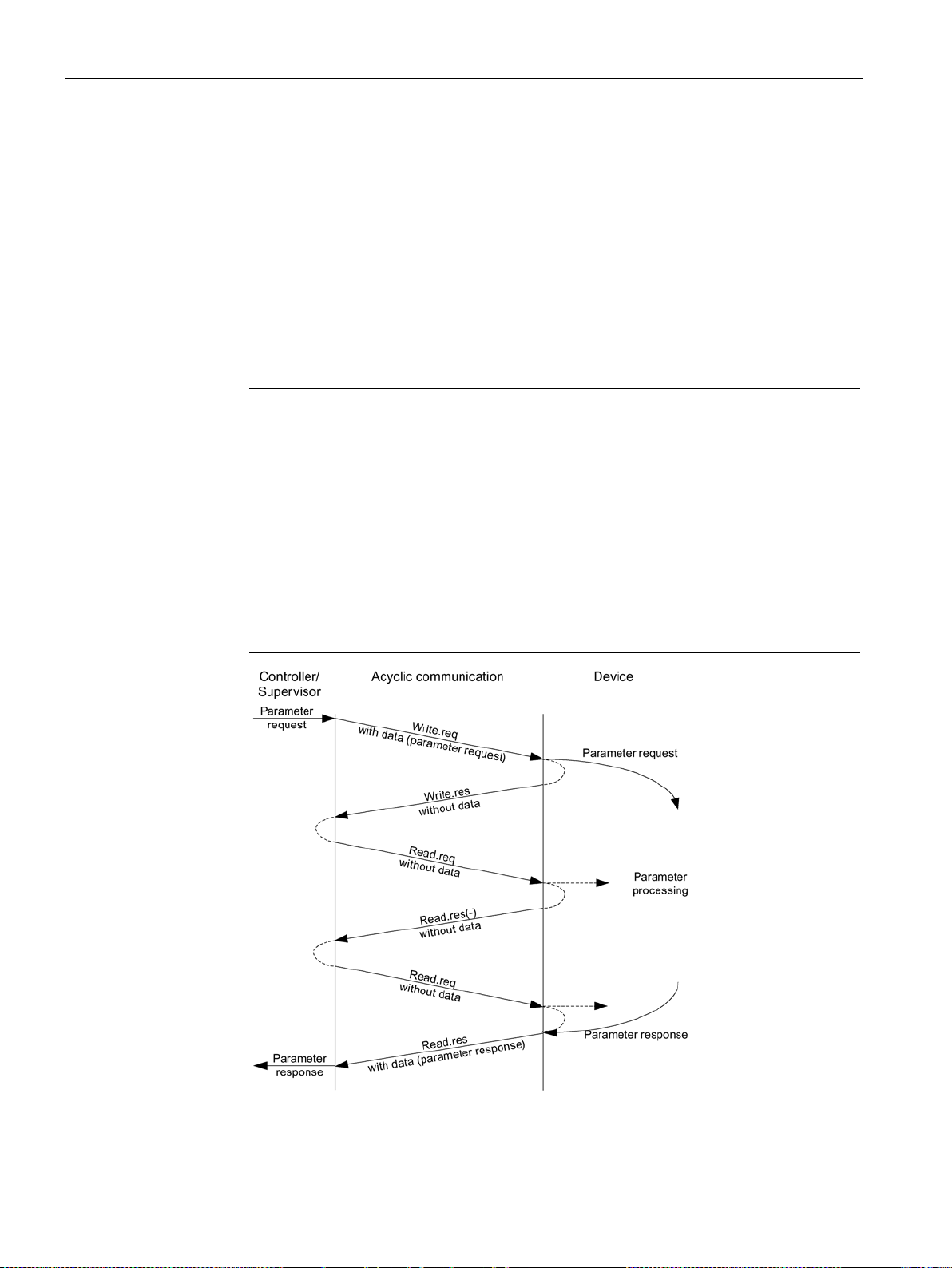
Communication according to PROFIdrive
Note
A detailed description of acyclic communication is provided in the following reference:
•
Addressing:
•
•
to a module as of slot 1. Parameters cannot be accessed via socket 0.
3.4 Acyclic communication
The following options are available for reading and writing parameters:
● S7 protocol
This protocol uses the Startdrive commissioning tool in online operation via
PROFIBUS/PROFINET.
● PROFIdrive parameter channel with the following data sets:
– PROFIBUS: Data block 47 (0x002F)
The DPV1 services are available for master class 1 and class 2.
– PROFINET: Data block 47 and 0xB02F al global access, data set 0xB02E as local
access
References: PROFIdrive profile
You can obtain the current version from "PROFIBUS and PROFINET International
(PI) (https://www.profibus.com/download/profidrive-profile-drive-technology/)".
PROFIBUS DP
The addressing is carried out via the logical address or the diagnostics address.
PROFINET IO
The addressing is only undertaken using a diagnostics address which is assigned
Figure 3-7 Reading and writing data
Communication
52 Function Manual, 12/2018, 6SL3097-5BD00-0BP0
Page 55

Communication according to PROFIdrive
Parameter request
Offset
Request reference
Request ID
0
Attribute
Number of elements
4
Subindex
8
...
Attribute
Number of elements
Parameter number
Subindex
Format
Number of values
Values
...
...
Format
Number of values
Values
...
3.4 Acyclic communication
Characteristics of the parameter channel
● One 16-bit address exists for each parameter number and subindex.
● Concurrent access by several additional PROFIBUS masters (master class 2) or
PROFINET IO supervisor (e.g. commissioning tool).
● Transfer of different parameters in one access (multiple parameter request).
● Transfer of complete arrays or part of an array possible.
● Only one parameter request is processed at a time for each controller/device connection
(no pipelining).
● A parameter request/response must fit into a data set (e.g. PROFIBUS: Max. 240 bytes).
● The request or the response header is user data.
3.4.2 Structure of requests and responses
Structure of parameter request and parameter response
Values for
write access
only
Request header
Axis Number of parameters 2
1st parameter address
Parameter number 6
nth parameter address
1st parameter value(s)
nth parameter value(s)
Communication
Function Manual, 12/2018, 6SL3097-5BD00-0BP0
53
Page 56

Communication according to PROFIdrive
Parameter response
Offset
Request reference mirrored
Response ID
0
Format
Number of values
4
Values or error values
6
...
...
Format
Number of values
Values or error values
...
Field
Data type
Values
Remark
Unsigned8
0x01 ... 0xFF
its response.
0x02
Write request
(p0971, p0977).
0x82
Write request (-)
The error values are transferred instead of the values for each subresponse.
Unsigned8
0x01 ... 0xFE
Number
same DPV1 connection.
Limited by DPV1 telegram length
The number of parameters = 1 for single requests.
0x30
Text (not implemented)
Type of parameter element accessed.
3.4 Acyclic communication
Values for
read access
only
Error values
for negative
response only
Response header
Axis mirrored Number of parameters 2
1st parameter value(s)
nth parameter value(s)
Description of fields in the parameter request and response
Request reference
Unique identification of the request/response pair for the controller. The controller changes
the request reference with each new request. The device mirrors the request reference in
Request ID Unsigned8 0x01
Specifies the type of request.
In the case of a write request, the changes are made in a volatile memory (RAM). A save
operation is needed in order to transfer the modified data to the non-volatile memory
Read request
Response ID Unsigned8 0x01
0x02
0x81
Mirrors the request identifier and specifies whether request execution was positive or negative.
Negative means:
Cannot execute part or all of request.
Drive object
number
Number of parameters Unsigned8 0x01 ... 0x27 No. 1 ... 39
Attribute Unsigned8 0x10
Specification of the drive object number for a drive unit with more than one drive object.
Different drive objects with separate parameter number ranges can be accessed over the
Defines the number of adjoining areas for the parameter address and/or parameter value
for multi-parameter requests.
0x20
Read request (+)
Write request (+)
Read request (-)
Value
Description
Communication
54 Function Manual, 12/2018, 6SL3097-5BD00-0BP0
Page 57

Communication according to PROFIdrive
Field
Data type
Values
Remark
Limited by DPV1 telegram length
Unsigned16
0x0001 ... 0xFFFF
No. 1 ... 65535
Addresses the parameter to be accessed.
Unsigned16
0x0000 ... 0xFFFE
Number 0 ... 65534
Addresses the first array element of the parameter to be accessed.
Other values
See the actual PROFIdrive profile
0x44
Error
Limited by DPV1 telegram length
Specifies the number of subsequent values.
sponses"
integrity of the word structure of the telegram.
Unsigned16
0x0000 ... 0x00FF
word structure of the telegram.
3.4 Acyclic communication
Number of elements Unsigned8 0x00
0x01 ... 0x75
Number of array elements accessed.
Parameter number
Subindex
Format Unsigned8 0x02
0x03
0x04
0x05
0x06
0x07
0x08
0x40
0x41
0x42
0x43
The format and number specify the adjoining space containing values in the telegram.
For write access, it is preferable to specify data types according to the PROFIdrive profile.
Bytes, words and double words are also possible as a substitute.
Number of values Unsigned8 0x00 ... 0xEA No. 0 ... 234
Special function
No. 1 ... 117
Data type integer8
Data type integer16
Data type integer32
Data type unsigned8
Data type unsigned16
Data type unsigned32
Data type floating point
Zero (without values as a positive
subresponse to a write request)
Byte
Word
Double word
Error values Unsigned16 0x0000 ... 0x00FF Significance of the error values
→ refer to the following table "Error
values in the DPV1 parameter re-
The error values in the event of a negative response.
If the values make up an odd number of bytes, a zero byte is attached. This ensures the
Values
The values of the parameter for read or write access.
If the number of bytes is odd, a zero byte is appended. This ensures the integrity of the
Communication
Function Manual, 12/2018, 6SL3097-5BD00-0BP0
55
Page 58

Communication according to PROFIdrive
Error
value
Meaning
Remark
Additional
info
0x00
Illegal parameter number.
Access to a parameter that does not exist.
–
0x02
Lower or upper value limit exceeded.
Modification access with value outside value limits.
Subindex
0x04
No array.
Access with subindex to an unindexed parameter.
–
data type of the parameter.
lowed).
where this is not allowed.
changed.
changed.
value exists).
active.
0x0B
No operating priority.
Modification access with no operating priority.
–
value exists).
operating status.
fined individual values).
transfer length.
these.
0x17
Illegal format.
Write request: Illegal or unsupported parameter data format.
–
the parameter address.
exist.
0x20
Parameter text cannot be changed
–
–
0x21
Service not supported.
Illegal or unknown request ID
–
and access to a V/f control parameter).
Write access is possible while the device is in the "Controller
SINAMICS S120/S150 List Manual (C1, C2, U, T).
3.4 Acyclic communication
Error values in parameter responses
0x01 Parameter value cannot be changed. Modification access to a parameter value that cannot be
changed.
0x03 Invalid subindex. Access to a subindex that does not exist. Subindex
0x05 Wrong data type. Modification access with a value that does not match the
0x06 Illegal set operation (only reset al-
0x07 Description element cannot be
0x09 No description data available. Access to a description that does not exist (the parameter
0x10 Read job will not be executed. The read request is refused because know-how protection is
0x0F No text array exists. Access to a text array that does not exist (the parameter
0x11 Request cannot be executed due to
0x14 Illegal value. Modification access with a value that is within the limits but
Modification access with a value not equal to 0 in a case
Modification access to a description element that cannot be
Access is temporarily not possible for unspecified reasons. –
is illegal for other permanent reasons (parameter with de-
Subindex
–
Subindex
Subindex
–
–
Subindex
0x15 Response too long. The length of the present response exceeds the maximum
0x16 Illegal parameter address. Illegal or unsupported value for attribute, number of ele-
0x18 Number of values inconsistent. Write request: A mismatch exists between the number of
0x19 Drive object does not exist. You have attempted to access a drive object that does not
0x65 Parameter presently deactivated. You have tried to access a parameter that, although availa-
0x6B Write access for enabled controller.
Communication
56 Function Manual, 12/2018, 6SL3097-5BD00-0BP0
–
–
ments, parameter number, subindex or a combination of
–
values in the parameter data and the number of elements in
–
–
ble, does not currently perform a function (e.g. n control set
–
enable" state.
Pay attention to the parameter attribute "changeable" in the
Page 59

Communication according to PROFIdrive
Error
value
Meaning
Remark
Additional
info
0x6C
Parameter %s [%s]: Unknown unit.
–
–
motor (p0010 = 3).
power unit (p0010 = 2).
mode (p0010 = 1).
only in the ready mode (p0010 = 0).
parameter reset (p0010 = 30).
Safety (p0010 = 95).
application/units (p0010 = 5).
(p0010 not equal to 0).
download (p0010 = 29).
ten during download.
configuration (device: p0009 = 3).
define drive type (device: p0009 = 2).
vice: p0009 = 4).
3.4 Acyclic communication
0x6D Parameter %s [%s]: Write access
only in the commissioning state,
encoder (p0010 = 4).
0x6E Parameter %s [%s]: Write access
only in the commissioning state,
0x6F Parameter %s [%s]: Write access
only in the commissioning state,
0x70 Parameter %s [%s]: Write access
only in the quick commissioning
0x71 Parameter %s [%s]: Write access
0x72 Parameter %s [%s]: Write access
only in the commissioning state,
0x73 Parameter %s [%s]: Write access
only in the commissioning state,
0x74 Parameter %s [%s]: Write access
only in the commissioning state, tech.
0x75 Parameter %s [%s]: Write access
only in the commissioning state
– –
– –
– –
– –
– –
– –
– –
– –
– –
0x76 Parameter %s [%s]: Write access
only in the commissioning state,
0x77 Parameter %s [%s] must not be writ-
0x78 Parameter %s [%s]: Write access
only in the commissioning state, drive
0x79 Parameter %s [%s]: Write access
only in the commissioning state,
0x7A Parameter %s [%s]: Write access
only in the commissioning state, data
record base configuration (de-
0x7B Parameter %s [%s]: Write access
only in the commissioning state,
device configuration (device: p0009 = 1).
Communication
Function Manual, 12/2018, 6SL3097-5BD00-0BP0
– –
– –
– –
– –
– –
– –
57
Page 60

Communication according to PROFIdrive
Error
value
Meaning
Remark
Additional
info
vice: p0009 = 29).
vice: p0009 = 30).
device ready (device: p0009 = 0).
device (device: p0009 not equal to 0).
ten during download.
by BI: p0806.
Parameter %s [%s]: Requested BICO
interconnection not possible.
however, requires a float value.
(refer to p0300, p0400, p0922)
is active.
lute" limits, is below the currently valid lower limit.
erned by the current converter rating).
Write access is not permitted because an access code is not
available.
3.4 Acyclic communication
0x7C Parameter %s [%s]: Write access
only in the commissioning state,
device download (de-
0x7D Parameter %s [%s]: Write access
only in the commissioning state,
device parameter reset (de-
0x7E Parameter %s [%s]: Write access
only in the commissioning state,
0x7F Parameter %s [%s]: Write access
only in the commissioning state,
0x81 Parameter %s [%s] must not be writ-
0x82 Transfer of master control is blocked
0x83
0x84 Parameter %s [%s]: Parameter
change inhibited
0x85 Parameter %s [%s]: Access method
not defined.
0x87 Write job will not be executed. The write request is rejected because know-how protection
– –
– –
– –
– –
– –
– –
BICO output does not supply float values. The BICO input,
– –
– –
–
–
0xC8 Below currently valid limit. Modification request for a value that, although within "abso-
0xC9 Above currently valid limit. Modification request for a value that, although within "abso-
lute" limits, is above the currently valid upper limit (e.g. gov-
0xCC Write access not permitted.
Communication
–
–
–
58 Function Manual, 12/2018, 6SL3097-5BD00-0BP0
Page 61

Communication according to PROFIdrive
3.4 Acyclic communication
3.4.3 Determining the drive object numbers
Further information about the drive system (e.g. drive object numbers) can be determined as
follows using parameters p0101, r0102, and p0107/r0107:
1. The value of parameter r0102 ("Number of drive objects") for drive object/axis 1 is read
via a read request.
Drive object 1 is the Control Unit (CU) which is a minimum requirement for each drive
system.
2. Depending on the result of the initial read request, further read requests for drive object 1
are used to read the indices for parameter p0101 "Drive object numbers", as specified by
parameter r0102.
Example:
If the number of drive objects is "5", the values of indices 0 to 4 of parameter p0101 are
read. Of course, the relevant indexes can also be read at once.
3. Following this, parameter r0107/p0107 ("Drive object type") is read for each drive
object/axis (indicated by the drive object number).
Depending on the drive object, parameter 107 can be either an adjustable parameter or a
display parameter.
The value in parameter r0107/p0107 indicates the drive object type. The coding for the
drive object type is specified in the parameter list.
Communication
Function Manual, 12/2018, 6SL3097-5BD00-0BP0
59
Page 62

Communication according to PROFIdrive
Parameter request
Offset
Request reference = 25 hex
Request ID = 01 hex
0 + 1
Attribute = 10 hex
Number of elements = 08 hex
4 + 5
Parameter no. = 945 dec
6
Subindex = 0 dec
8
3.4 Acyclic communication
3.4.4 Example 1: read parameters
Requirements
● The PROFIdrive controller has been commissioned and is fully operational.
● PROFIdrive communication between the controller and the device is operational.
● The controller can read and write data sets in conformance with PROFINET/PROFIBUS.
Task description
Following the occurrence of at least one fault (ZSW1.3 = "1") on drive 2 (also drive object
number 2), the active fault codes must be read from the fault buffer r0945[0] ... r0945[7].
The request is to be handled using a request and response data block.
Basic procedure
1. Create a request to read the parameters.
2. Invoke the request.
3. Evaluate the response.
Create the request
Information about the parameter request:
● Request reference:
● Request ID:
● Axis:
Request header
Axis = 02 hex Number of parameters = 01 hex 2 + 3
Parameter address
The value is selected at random from the valid value range. The request reference
establishes the relationship between request and response.
01 hex → This identifier is required for a read request.
Communication
60 Function Manual, 12/2018, 6SL3097-5BD00-0BP0
02 hex → Drive 2, fault buffer with drive- and device-specific faults.
● Number of parameters:
01 hex → One parameter is read.
Page 63

Communication according to PROFIdrive
Parameter response
Offset
25 hex
Axis mirrored = 02 hex
Number of parameters = 01 hex
2 + 3
Format = 06 hex
Number of values = 08 hex
4 + 5
2nd value = 0 dec
8
...
...
8th value = 0 dec
20
3.4 Acyclic communication
● Attribute:
10 hex → The parameter values are read.
● Number of elements:
08 hex → The actual fault incident with eight faults is to be read.
● Parameter number:
945 dec → p0945 (fault code) is read.
● Subindex:
0 dec → Reading starts at index 0.
Initiate parameter request.
If ZSW1.3 = "1" → Initiate parameter request
Evaluate the parameter response.
Response header Request reference mirrored =
Parameter value
1st value = 1355 dec 6
Response ID = 01 hex 0 + 1
Information about the parameter response:
● Request reference mirrored:
This response belongs to the request with request reference 25.
● Response ID:
01 hex → Read request positive, values stored as of 1st value.
● Axis mirrored, number of parameters:
The values correspond to the values from the request.
● Format:
06 hex → Parameter values are in the unsigned16 format.
● Number of values:
Communication
Function Manual, 12/2018, 6SL3097-5BD00-0BP0
08 hex → Eight parameter values are available.
● 1st value ... 8th value
A fault is only entered in value 1 of the fault buffer for drive 2.
61
Page 64
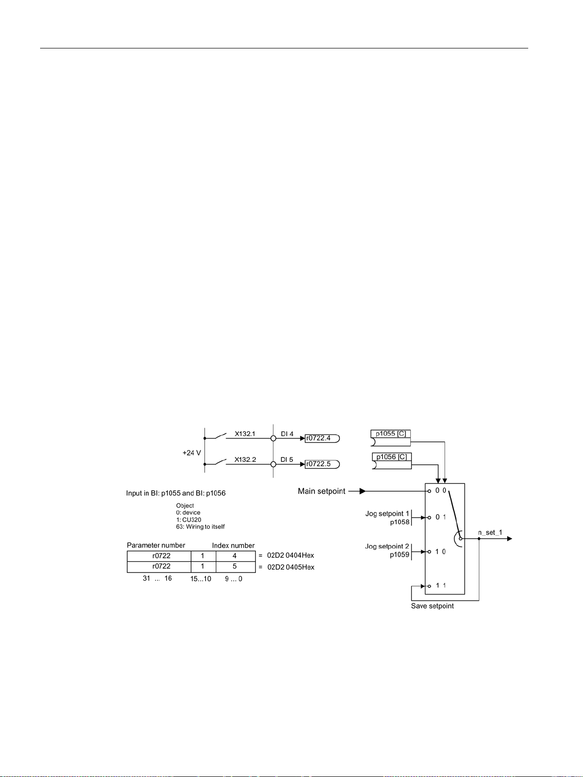
Communication according to PROFIdrive
•
Jog bit 0
•
Jog bit 1
•
Jog 1 speed setpoint
•
Jog 2 speed setpoint
3.4 Acyclic communication
3.4.5 Example 2: Writing parameters (multi-parameter request)
Requirements
● The PROFIdrive controller has been commissioned and is fully operational.
● PROFIdrive communication between the controller and the device is operational.
● The controller can read and write data sets in conformance with PROFINET/PROFIBUS.
Special requirements for this example:
● Servo control or vector control with activated "Extended setpoint channel" function
module
Task description
Jog 1 and 2 are to be set up for drive 2 (also drive object number 2) via the input terminals of
the Control Unit. A parameter request is to be used to write the corresponding parameters as
follows:
BI: p1055 = r0722.4
BI: p1056 = r0722.5
p1058 = 300 rpm
p1059 = 600 rpm
The request is to be handled using a request and response data block.
Figure 3-8 Task description for multi-parameter request (example)
Communication
62 Function Manual, 12/2018, 6SL3097-5BD00-0BP0
Page 65

Communication according to PROFIdrive
Parameter request
Offset
hex
Axis = 02 hex
Number of parameters = 04 hex
2 + 3
Attribute = 10 hex
Number of elements = 01 hex
4 + 5
Subindex = 0 dec
8
Attribute = 10 hex
Number of elements = 01 hex
10 + 11
Parameter no. = 1056 dec
12
Subindex = 0 dec
14
Attribute = 10 hex
Number of elements = 01 hex
16 + 17
Parameter no. = 1058 dec
18
Subindex = 0 dec
20
Attribute = 10 hex
Number of elements = 01 hex
22 + 23
Parameter no. = 1059 dec
24
Subindex = 0 dec
26
Format = 07 hex
Number of values = 01 hex
28 + 29
Value = 02D2 hex
30
Value = 0404 hex
32
Format = 07 hex
Number of values = 01 hex
34 + 35
Value = 02D2 hex
36
Value = 0405 hex
38
Format = 08 hex
Number of values = 01 hex
40 + 41
Value = 4396 hex
42
Format = 08 hex
Number of values = 01 hex
46 + 47
Value = 4416 hex
48
Value = 0000 hex
50
3.4 Acyclic communication
Basic procedure
1. Create a request to write the parameters.
2. Invoke the request.
3. Evaluate the response.
Create the request
Request header Request reference = 40
1st parameter address
2nd parameter address
3rd parameter address
4th parameter address
1st parameter value(s)
2nd parameter value(s)
Parameter no. = 1055 dec 6
Request ID = 02 hex 0 + 1
Communication
Function Manual, 12/2018, 6SL3097-5BD00-0BP0
3rd parameter value(s)
Value = 0000 hex 44
4th parameter value(s)
63
Page 66

Communication according to PROFIdrive
3.4 Acyclic communication
Notes relating to the parameter request:
● Request reference:
The value is selected at random from the valid value range. The request reference
establishes the relationship between request and response.
● Request ID:
02 hex → This identifier is required for a write request.
● Axis:
02 hex → The parameters are written to drive 2.
● Number of parameters
04 hex → The multi-parameter request comprises four individual parameter requests.
1st parameter address ... 4. Parameter address
● Attribute:
10 hex → The parameter values are to be written.
● Number of elements
01 hex → One array element is written.
● Parameter number
Specifies the number of the parameter to be written (p1055, p1056, p1058, p1059).
● Subindex:
0 dec → ID of the first array element.
1st parameter value ... 4th Parameter value
● Format:
07 hex → Data type, unsigned32
08 hex → Data type, floating point
● Number of values:
01 hex → A value is written to each parameter in the specified format.
● Value:
BICO input parameter: Enter signal source
Adjustable parameter: Enter value
Initiate parameter request.
Communication
64 Function Manual, 12/2018, 6SL3097-5BD00-0BP0
Page 67

Communication according to PROFIdrive
Parameter response
Offset
Request reference mirrored = 40 hex
Response ID = 02 hex
0
04 hex
3.4 Acyclic communication
Evaluate the parameter response.
Response header
Axis mirrored = 02 hex Number of parameters =
Notes regarding the parameter response:
● Request reference mirrored:
This response belongs to the request with request reference 40.
● Response ID:
02 hex → Write request positive
● Axis mirrored:
02 hex → The value matches the value from the request.
● Number of parameters:
04 hex → The value matches the value from the request.
2
Communication
Function Manual, 12/2018, 6SL3097-5BD00-0BP0
65
Page 68

Communication according to PROFIdrive
•
•
•
•
•
•
PROFIdrive message classes
Faults
Alarms
Component assignment
GSDML X X
X
TIA
X X X
TIA
X - -
Note
Constraint
If a shared device is activated, only the A
Note
Additional information
PROFIdrive message classes of the individual SINAMICS fa
the SINAMICS List Manuals.
3.5 Diagnostics channels
3.5 Diagnostics channels
SINAMICS drives provide the standard diagnostics for PROFIBUS and PROFINET. This
allows the PROFIdrive classes of the SINAMICS drive to be integrated into the system
diagnostics of a higher-level control system and automatically displayed on an HMI.
The information transferred is saved for the drive objects in the following parameters:
r0947[0...63] fault number
r3120[0..63] component fault
r2122[0...63] alarm code
r9747[0...63] SI message code
(with safety messages)
r3121[0..63] component alarm
r9745[0..63] SI component
(with safety message)
The messages entered in these parameters are combined to create PROFIdrive message
classes for diagnostics. Determining the source of a message is realized by transferring the
component number as channel number.
The diagnostics are activated through appropriate parameterization in the configuring tools
used (e.g. using HW Config or via HWCN in the TIA Portal).
The functional scope of the diagnostic channels depends on the bus system.
PN
DP GSD X - -
● SINAMICS transfers the messages in the sequence in which they occurred.
● If an alarm appears, SINAMICS sends an "incoming" message. The alarm remains until
SINAMICS sends the corresponding "outgoing" message.
● The time stamps are generated from the higher-level controller when the messages are
received
● The existing mechanisms of TIA and S7 Classic can be used.
● Alarms or faults are acknowledged using the already known acknowledgment routes.
● Transfer is possible via interface IF1 and/or IF2.
Communication
66 Function Manual, 12/2018, 6SL3097-5BD00-0BP0
-controller can receive diagnostics.
ults and alarms are provided in
Page 69
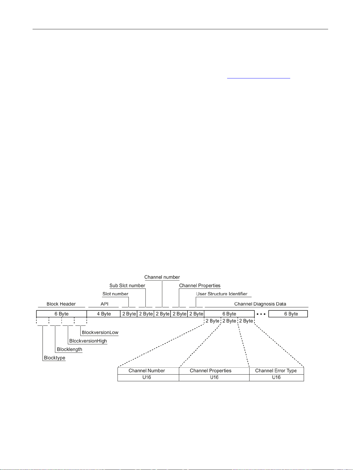
Communication according to PROFIdrive
3.5 Diagnostics channels
3.5.1 PROFINET-based diagnostics
For PROFINET, to transfer PROFIdrive message classes, channel diagnostics (Channel
Diagnosis) are used (see PROFINET IO specification (http://www.profibus.com)).
A message always comprises the following components in this specific sequence:
● Block Header (6 Byte)
– Blocktype
– Blocklength
– BlockversionHigh
– BlockversionLow
● API (4 Byte)
● Slot Number (2 Byte)
● Sub Slot Number (2 Byte)
● Channel Number (2 Byte)
● Channel Properties (0x8000) (2 Byte)
● User Structure Identifier (2 Byte)
● Channel Diagnosis Data (6 Byte)
– Channel Number (2 Byte)
– Channel Properties (2 Byte)
– Channel Error Type (2 Byte)
Overview:
Figure 3-9 Components of a message
Communication
Function Manual, 12/2018, 6SL3097-5BD00-0BP0
67
Page 70

Communication according to PROFIdrive
Designation
Data
type/length
For SINAMICS
Value
Significance
Channel Properties
U16
.Type
Bits 7 ... 0
0
No data length
.Accumulative
Bit 8
0
1 channel; no group formation
2
3
Message issued, additional messages are available in the channel
13
0x9013
Auxiliary unit faulted
1)
For messages, which cannot be assigned to any particular component
3.5 Diagnostics channels
Individual components of the Channel Diagnosis Data block can be included n times in a
message. A precise explanation of these message components is subsequently provided:
Channel Number U16 1 ... 399
0x8000
.Maintenance Bits 10, 9 0
1
.Specifier Bits 12, 11 0
1
2
.Direction Bits 15 ...
Channel Error Type U16 0x9000
3 Input/Output
0x9001
0x9002
0x9003
0x9004
0x9005
0x9006
0x9007
0x9008
0x9009
0x900A
0x900B
0x900C
0x900E
0x900F
0x9010
0x9011
0x9012
Component number
1)
No component assignment
Fault → diagnostics
Alarm, Class 0 or A → maintenance
Alarm, Class B or C → maintenance
Not used
Message received
Message issued, no additional message available in the channel
Hardware / software error
Network fault
Supply voltage fault
DC link overvoltage
Power electronics faulted
Overtemperature of the electronic components
Ground fault / inter-phase short circuit
Motor overload
Communication error to the higher-level control system
Safety monitoring channel has identified an error
Position/speed actual value incorrect or not available
Internal (DRIVE-CLiQ) communication error
Infeed faulted
Line filter faulted
External measured value / signal state outside the
permissible range
Application / technological function faulted
Error in the parameterization / configuration /
commissioning procedure
General drive fault
required
demanded
Communication
68 Function Manual, 12/2018, 6SL3097-5BD00-0BP0
Page 71

Communication according to PROFIdrive
Note
If a fault is active on the CU drive object, then this fault is propagated to all of the drive
objects associated with the CU. This fault can therefore be read out at each
3.5 Diagnostics channels
System response - reading out diagnostics data
The converter can request diagnostics data via "Read data set" (detailed information is
provided in the PROFINET-IO specification (http://www.profibus.com)).
Example:
For example, a read record with index 0x800C can be used to read out diagnostics data from
specific sub slots. The following rules apply as example:
● 1 message block
if, at this drive object (one or several) faults of the same message class are identified
● n messages
if, at this drive object, n faults of different message classes are identified
drive object.
Communication
Function Manual, 12/2018, 6SL3097-5BD00-0BP0
69
Page 72

Communication according to PROFIdrive
Note
The master must operate in the DPV1 mode.
3.5 Diagnostics channels
3.5.2 PROFIBUS-based diagnostics
For communication via PROFIBUS, in the case of fault the following diagnostics data is
output:
● Standard diagnostics (Page 71)
● Identifier-related diagnostics (Page 71)
● Status messages/module status (Page 72)
● Channel-related diagnostics (Page 73)
● Data sets DS0/DS1 and diagnostics alarm (Page 74)
Message structure
The following applies if a message contains all of the specified diagnostics data:
● Standard diagnostics
Is always located at the beginning of the message.
● Data sets DS0/DS1 and diagnostics alarm
Is always located at the end of the message. This message part is always slot-specific.
The actual state of the slot responsible for the message is always transferred in the
message.
The other diagnostics data (types) can be in any sequence. This is the reason that the
following diagnostics data include a header:
● Identifier-related diagnostics
● Status messages/module status
● Channel-related diagnostics
The diagnostic data type can be uniquely identified based on the header.
Communication
70 Function Manual, 12/2018, 6SL3097-5BD00-0BP0
Page 73

Communication according to PROFIdrive
Bit
7 6 5 4 3 2 1
0
Octet
Name
Ext_Diag
= 0
Stat_Diag
= 0
Ext_
Diag_
Overflow
4
Master_Add
5
Ident_Number (HighByte) of the slave
6
Ident_Number (LowByte) of the slave
Bit
7 6 5 4 3 2 1
0
Octet
Name
status 1
structure
structure
...
...
3.5 Diagnostics channels
3.5.2.1 Standard diagnostics
For communication via PROFIBUS, standard diagnostics is structured as follows.
1 Station
status 1
2 Station
status 2
3 Station
status 3
Master_
Lock
= 0
0 0 Sync_
Prm_Fault 0 Not_
0 0 0 0 0 0 0
Mode
Supported
Freeze_
Mode
WD_On 1
Cfg_Fault Station_
In this context, the following values are decisive for diagnostics:
● Ext_Diag
– Group signal for diagnostics in the slave
– = 1, if at least 1 alarm is active
● Ext_Diag_Overflow
Display, diagnostics overflow in the slave (for more than 240 bytes)
Not_
Ready
Station_
Non_
Exist
Prm_Req
3.5.2.2 Identifier-related diagnostics
The identifier-related diagnostics provides a bit (KB_n) for each slot 1 allocated when
configuring the device. If a diagnostics message is active at a slot, then it's KB_n = true.
1 Header-
Byte
Station
2 Bit
3 Bit
x Bit
structure
Communication
Function Manual, 12/2018, 6SL3097-5BD00-0BP0
0 1 Block length (2 ... 32) incl. this byte
KB_7 KB_6 KB_5 KB_4 KB_3 KB_2 KB_1 KB_0
... ... ... ... KB_11 KB_10 KB_9 KB_8
... ... KB_n+1 KB_n ... ... ... ...
71
Page 74
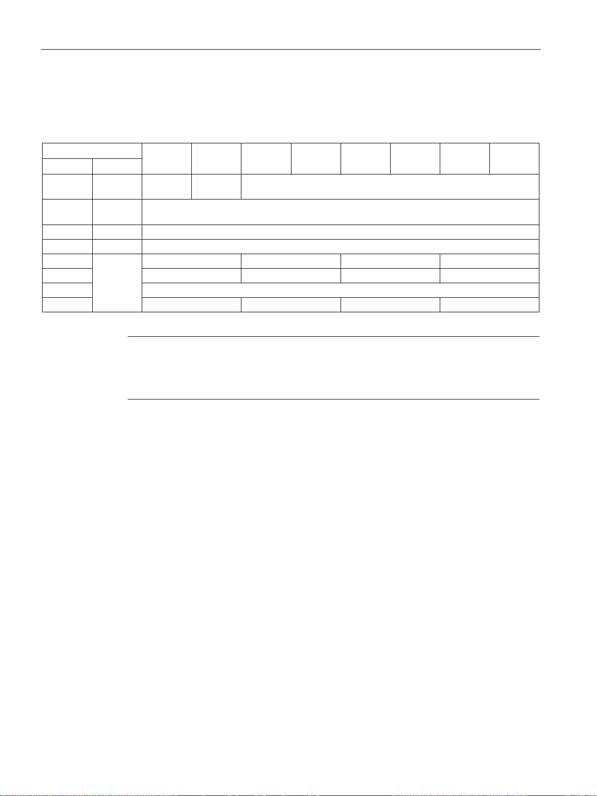
Communication according to PROFIdrive
Bit
7 6 5 4 3 2 1
0
Octet
Name
byte
status
3
Slot
0
4
Specifier
0
5 Slot_4
Slot_3
Slot_2
Slot_1
6
...
Slot_7
Slot_6
Slot_5
...
...
x
00
Slot_n
...
...
Note
Status value
Diagnostics for SINAMICS are only available in cyclic PROFIBUS operation, so that the state
00
3.5 Diagnostics channels
3.5.2.3 Status messages/module status
Status messages and module status briefly represent an overview of the state of the
devices:
1 Header
2 Module
0 0 Block length (2 ... 32) incl. this byte
0x82
= "Valid useful data" is always output for all slots.
Communication
72 Function Manual, 12/2018, 6SL3097-5BD00-0BP0
Page 75

Communication according to PROFIdrive
Bit
7 6 5 4 3 2 1
0
Octet
Name
Byte
x + 1 12)
12)
0 (no component assignment)
31 Parameterization/commiss. error
1)
2)
3)
≙ "Channel type "non specific"
3.5 Diagnostics channels
3.5.2.4 Channel-related diagnostics
Channel-related diagnostics encompasses the following data:
x Header-
11) 01) 0 ... 63 (module number) including this byte
x + 2 03) 03) Message classes:
2 undervoltage
3 overvoltage
9 error
16 Hardware/software error
17 Line supply/filter faulted
18 DC-link overvoltage
19 Power electronics faulted
20 Electronic component overtemp.
21 Ground/phase fault detected
22 Motor overload
23 Commun. with controller faulted
24 Safety monit. Detected an error
25 Act. Position/speed value error
26 Internal communication faulted
27 Infeed faulted
28 Braking controller faulted
29 External signal state error
30 Application/function faulted
≙ Channel-related diagnostics
≙ Input/output
Communication
Function Manual, 12/2018, 6SL3097-5BD00-0BP0
System response
Only one signal is generated if channel-related diagnostics identifies several faults belonging
to the same message class at the same drive object.
73
Page 76
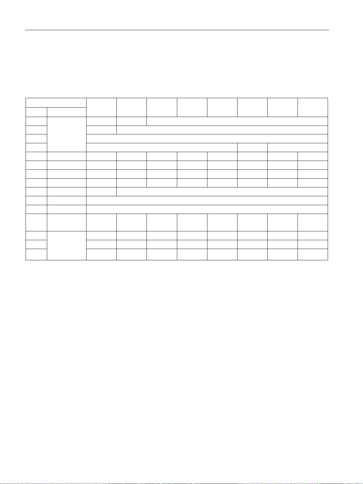
Communication according to PROFIdrive
Bit
7 6 5 4 3 2 1
0
Octet
Name
2
0
= 1 (diagnostics alarm)
3
0 ... 244 (slot number ≙ drive object)
4
0 ... 31 (sequence number)
Add_Ack
Alarm_Specifier1)
5
DS0 (byte 0)
0 0 0 0 12) 0 13)
14)
6
DS0 (byte 1)
0 0 0
15)
06)
06)
16)
16)
7
DS0 (Byte 2)
0 0 0 0 0 0 0
0
8
DS0 (byte 3)
0 0 0 0 0 0 0
0
9
Info (byte 1)
Mixed
= 0x45 (ChannelTypeID = SINAMICS)
10
Info (byte 2)
= 24 (number of diagnostic bits/channel)
11
Info (byte 3)
= 1 (1 channel signals)
1
13
(channel 0)
Err 7
Err 6
Err 5
Err 4
Err 3
Err 2
Err 1
Err 0
14
Err 15
Err 14
Err 13
Err 12
Err 11
Err 10
Err 9
Err 8
1)
2)
3)
4)
5)
6)
= 0011; ≙ Distributed
3.5 Diagnostics channels
3.5.2.5 Data sets DS0/DS1 and diagnostics alarm
The PROFIdrive message classes are transferred using diagnostic alarm DS0/DS1. All faults
are assigned channel 0. The drive objects are assigned using the slot number.
The structure is as follows:
1 Header-Byte 0 0 = 15 (block length)
12 Channel Error
0 0 0 0 0 0 0 Channel 0
Vector
Channel
-related diag-
15 0 0 0 0 Err 19 Err 18 Err 17 Err 16
nostics
Alarm_Specifier
1 ≙ error has occurred and the slot is not OK
2 ≙ error is resolved and the slot is OK
3 ≙ error is resolved and the slot is not okay
Channel fault present
= 1; as long as the drive object has an error condition
Internal fault
= 1; as long as the drive object has an error condition
Module fault
= 1; as long as the drive object has an error condition
Channel information present
= 1; ≙ DS1 exists
Type class of module
Communication
74 Function Manual, 12/2018, 6SL3097-5BD00-0BP0
Page 77

Communication according to PROFIdrive
3.6 Configuring telegrams in Startdrive
3.6 Configuring telegrams in Startdrive
Description
If communication is established between the drive and higher-level control system via
PROFINET IO, then the data (setpoints and actual values) are cyclically transferred using
PROFIdrive telegrams.
To configure a cyclic data transfer, proceed as follows:
● Insert the drive and controller
● Insert a PROFINET subnet
● Assign the drive to the controller
● Check the bus settings
● Parameterize the drive
You must create telegrams for the relevant drive objects, e.g. for drive axes, drive control
or infeed
● Check and edit the telegram settings
● If you are controlling a drive with safety functions via PROFIsafe, you must insert the
appropriate PROFIsafe telegram.
3.6.1 Displaying telegram configuration
The "Telegram configuration" screen form is part of the device configuration and is displayed
in the inspector window.
You can call this screen form, either via the project navigation or via direct links from the
communication screen forms.
Call the telegram configuration via the project navigation
1. Open the drive device in the project navigation.
2. Double-click on the entry "Device configuration."
The device configuration opens.
3. Select the entry "Telegram configuration" in the "Properties" tab of the inspector window.
The telegram configuration settings are displayed under the respective fieldbus interface
Communication
Function Manual, 12/2018, 6SL3097-5BD00-0BP0
75
Page 78
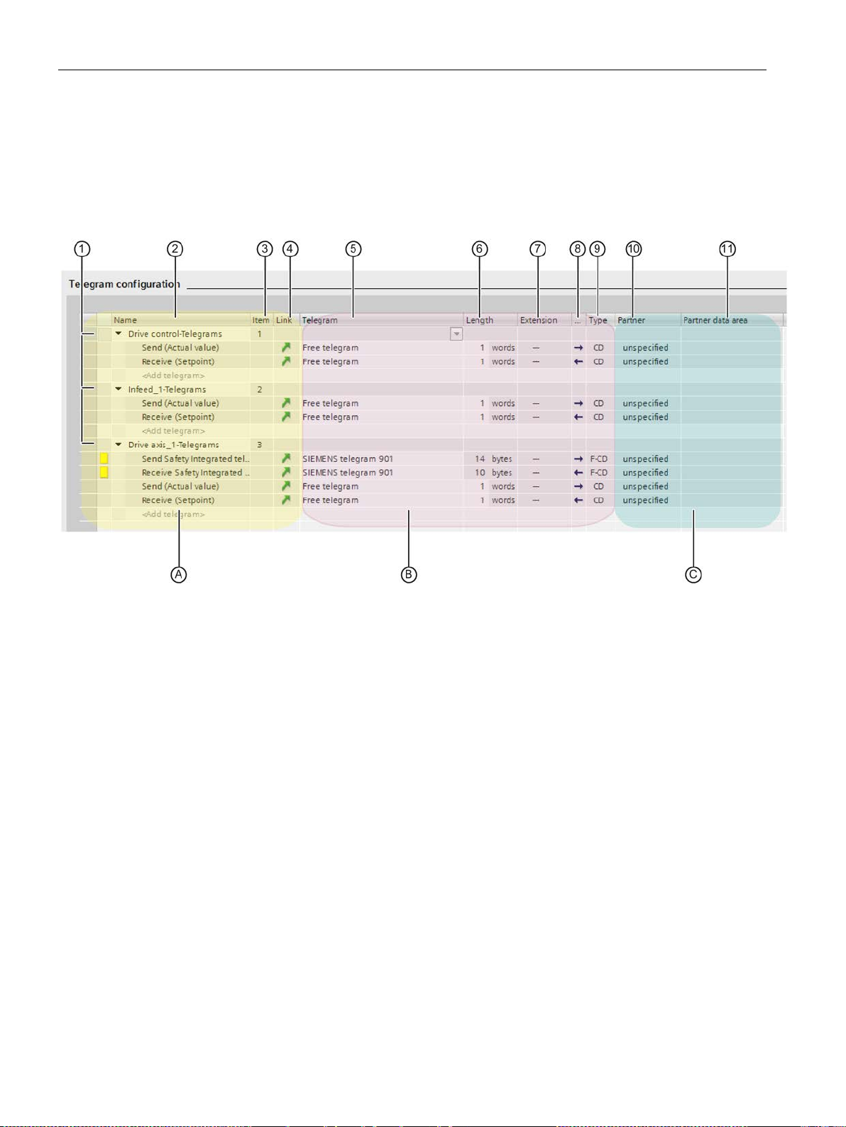
Communication according to PROFIdrive
3.6 Configuring telegrams in Startdrive
3.6.2 Settings for SINAMICS S120, S150, G150, G130, MV
Telegram configuration
The dialog box for the telegram configuration is structured as follows:
Figure 3-10 Example: Telegram configuration with several drive objects
Communication
76 Function Manual, 12/2018, 6SL3097-5BD00-0BP0
Page 79

Communication according to PROFIdrive
Number
Description
drive object for setpoints and actual values. "Free telegram" is selected by default.
B
Area for the interfaces
C
Area for the communication partners of the drive (e.g. controller or another drive)
①
tion.
②
configuration, and can no longer be changed. Resorting in the table does not change this number.
④
⑤
⑥
⑦
⑧
Type of communication
CD = Controller - Device for PROFINET IO
⑩
⑪
3.6 Configuring telegrams in Startdrive
A Area for the drive objects (setpoints, actual values and safety components). A telegram is assigned to each
③
⑨
Header of a drive object
Using the header, you can move the drive object in the list with drag and drop (in the first column). This
changes the sorting in the table and at the same time in the secondary navigation of the telegram configura-
Display of the drive object
Number of the drive object
This number is generated automatically according to the order in which a drive object is created in the device
Link to the communication screen forms of the particular drive object
Drop-down list with the available telegrams
Telegram length
Telegram extension
Communication direction (send direction
F_ = PROFIsafe-specific extension (safety telegram)
Name of the partner (controller)
I/O addresses of the controller
/receive direction )
Communication
Function Manual, 12/2018, 6SL3097-5BD00-0BP0
77
Page 80

Communication according to PROFIdrive
3.6 Configuring telegrams in Startdrive
Communication
78 Function Manual, 12/2018, 6SL3097-5BD00-0BP0
Page 81

4
Note
PROFIBUS for drive technology is standardized a
PROFIdrive Profile Drive Technology
PROFIBUS User Organization e. V.
Haid
Internet: (
Note
Startdrive
Plea
Note
Before synchronizing to the isochronous PROFIBUS, all of the drive object pulses must be
inhibited
PROFIBUS interface: T
CBE20
NOTICE
Destruction of the CU320-2 or other CAN bus nodes by connecting a CAN cable
4.1 General information about PROFIBUS
4.1.1 General information about PROFIBUS for SINAMICS
PROFIBUS is an open international fieldbus standard for a wide range of production and
process automation applications.
The following standards ensure open, multi-vendor systems:
● International standard EN 50170
● International standard IEC 61158
PROFIBUS is tuned for high-speed, time-critical data communication at field level.
nd described in the following document:
-und-Neu-Strasse 7, D-76131 Karlsruhe
http://www.profibus.com)
se note that you still cannot use this function with Startdrive.
- also for those drives that are not controlled via PROFIBUS.
he cyclic PZD channel is deactivated when the
Connecting a CAN cable to interface X126 of the CU320-2 can destroy the CU320-2 or
other CAN bus nodes.
• Do not connect any CAN cable to the X126 interface.
is plugged in!
Communication
Function Manual, 12/2018, 6SL3097-5BD00-0BP0
79
Page 82
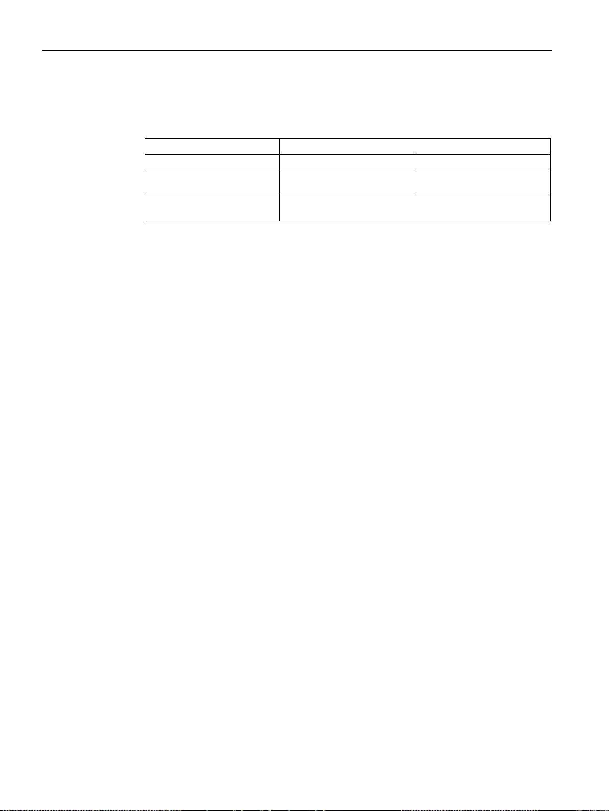
Communication via PROFIBUS DP
Properties
Master
Slave
As bus node
Active
Passive
request
master
strictions
permitted
4.1 General information about PROFIBUS
Master and slave
● Master and slave properties
● Master
● Slaves
Bus access method
Send messages Permitted without external
Receive messages Possible without any re-
Only possible on request by
Only receive and acknowledge
The following classes are differentiated:
– Master class 1 (DPMC1):
Central automation stations that exchange data with the slaves in cyclic and acyclic
mode. Communication between the masters is also possible.
Examples: SIMATIC S7, SIMOTION
– Master class 2 (DPMC2):
Devices for configuration, commissioning, operator control and monitoring during bus
operation. Devices that only exchange data with the slaves in acyclic mode.
Examples: Programming devices, human machine interfaces
With respect to PROFIBUS, the SINAMICS drive unit is a slave.
PROFIBUS uses the token passing method, i.e. the active stations (masters) are arranged in
a logical ring in which the authorization to send is received within a defined time frame.
Within this time frame, the master with authorization to send can communicate with the
assigned slaves and/or with other masters in a master/slave procedure.
PROFIBUS telegram for cyclic data transmission and acyclic services
Each drive unit that supports cyclic process data exchange uses a telegram to send and
receive all the process data. A separate telegram is sent in order to perform all the acyclic
services (read/write parameters) under a single PROFIBUS address. The acyclic data is
transferred with a lower priority after cyclic data transmission.
The overall length of the telegram increases with the number of drive objects that are
involved in exchanging process data.
Communication
80 Function Manual, 12/2018, 6SL3097-5BD00-0BP0
Page 83

Communication via PROFIBUS DP
Note
The sequence of drive
Drive objects after the first zero in p0978 must not be configured in the HW Config.
4.1 General information about PROFIBUS
Sequence of drive objects in the telegram
On the drive side, the sequence of drive objects in the telegram is displayed via a list in
p0978[0...24] where it can also be changed.
Using the Startdrive commissioning tool you can display the sequence of drive objects for a
commissioned drive system in the project navigator under "Drive unit"
"Telegram configuration".
When you create the configuration on the controller side (e.g. HW Config), the process-datacapable drive objects for the application are added to the telegram in the sequence shown
(see above).
The following drive objects can exchange process data:
● Active Infeed (A_INF)
● Basic Infeed (B_INF)
● Control Unit (CU_S)
● ENC
● Smart Infeed (S_INF)
> "Communication" >
● SERVO
● Terminal Board 30 (TB30)
● Terminal Module 15 (TM15)
● Terminal Module 31 (TM31)
● Terminal Module 41 (TM41)
● Terminal Module 120 (TM120)
● Terminal Module 150 (TM150)
● VECTOR
objects in HW Config must be the same as that in the drive (p0978).
The structure of the telegram depends on the drive objects taken into account during
configuration. Configurations are permitted that do not take into account all of the drive
objects that are present in the drive system.
Example:
The following configurations, for example, are possible:
● Configuration with SERVO, SERVO, SERVO
● Configuration with A_INF, SERVO, SERVO, SERVO, TB30
● etc.
Communication
Function Manual, 12/2018, 6SL3097-5BD00-0BP0
81
Page 84
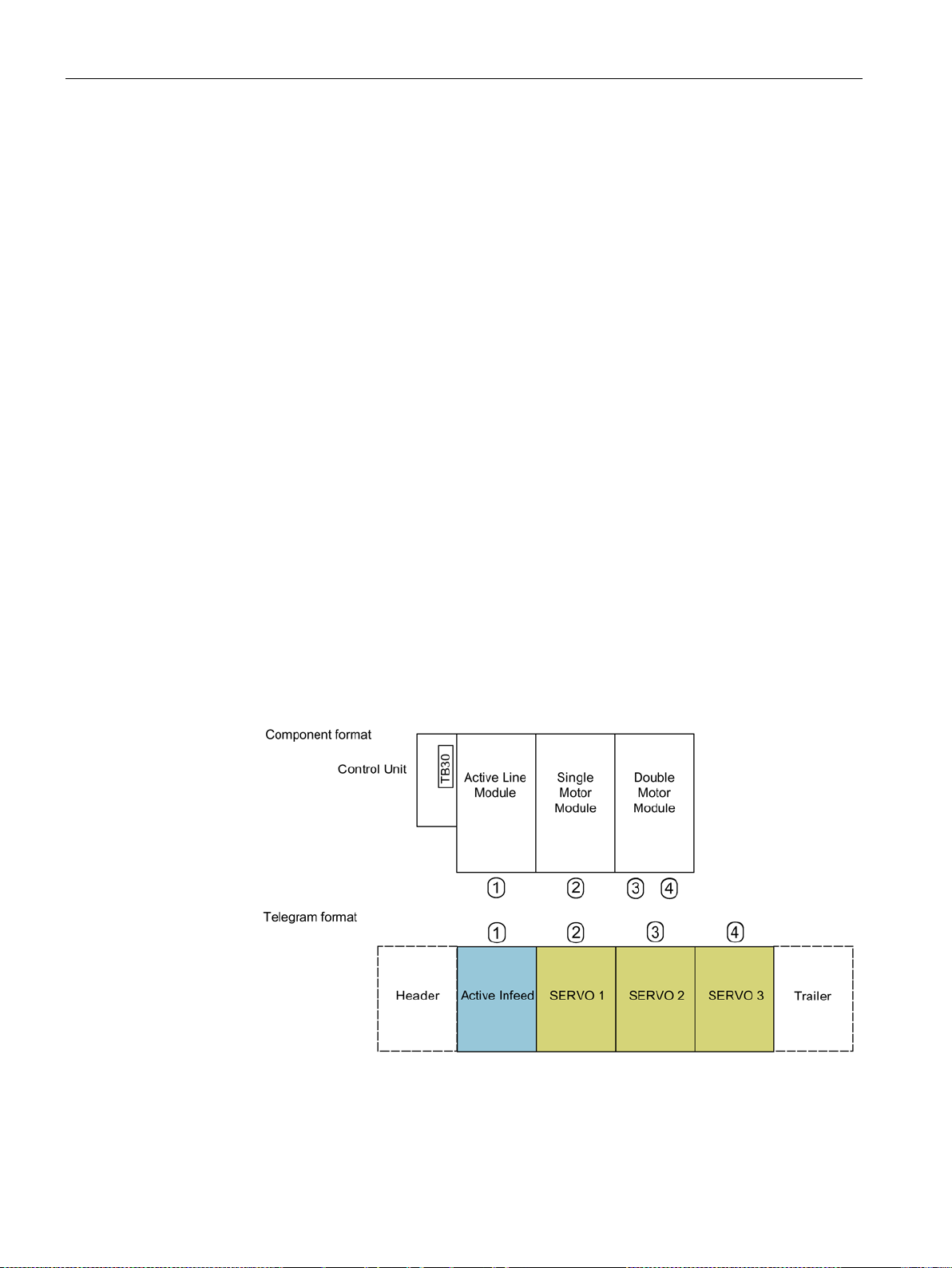
Communication via PROFIBUS DP
4.1 General information about PROFIBUS
4.1.2 Example: telegram structure for cyclic data transmission
Task
The drive system comprises the following drive objects:
● Control Unit (CU_S)
● Active Infeed (A_INF)
● SERVO 1 (comprises a Single Motor Module and other components)
● SERVO 2 (comprises a Double Motor Module terminal X1 and other components)
● SERVO 3 (comprises a Double Motor Module terminal X2 and other components)
● Terminal Board 30 (TB30)
The process data is to be exchanged between the drive objects and the higher-level
automation system.
Telegrams to be used:
● Telegram 370 for Active Infeed
● Standard telegram 6 for SERVO
● User-defined for Terminal Board 30 for the three SERVO drives
Component and telegram structure
The predefined component structure results in the telegram structure shown in the following
diagram.
Figure 4-1 Component and telegram structure
You can check and change the sequence of the telegrams via p0978[0...24].
Communication
82 Function Manual, 12/2018, 6SL3097-5BD00-0BP0
Page 85
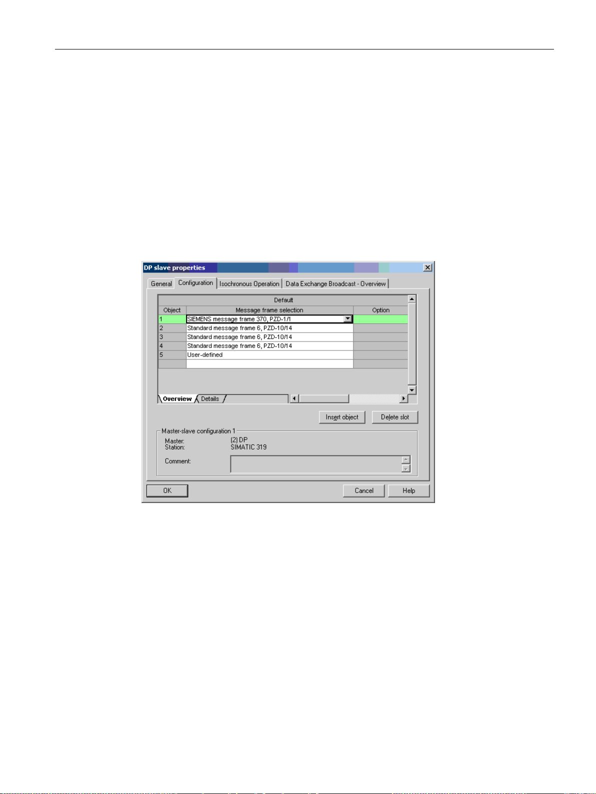
Communication via PROFIBUS DP
•
Telegram 370
•
Standard telegram 6
•
Standard telegram 6
•
Standar
•
User
4.1 General information about PROFIBUS
Configuration settings (e.g. HW Config for SIMATIC S7)
Due to the telegram structure shown, the objects in the "DP slave properties" overview must
be configured as follows:
Active Infeed (A_INF):
SERVO 1:
SERVO 2:
SERVO 3:
Terminal Board 30 (TB30):
DP slave properties – overview
d telegram 6
-defined
Communication
Function Manual, 12/2018, 6SL3097-5BD00-0BP0
Figure 4-2 Slave properties – overview
When you click "Details", the properties of the configured telegram structure are displayed
(e.g. I/O addresses, axis separator).
83
Page 86
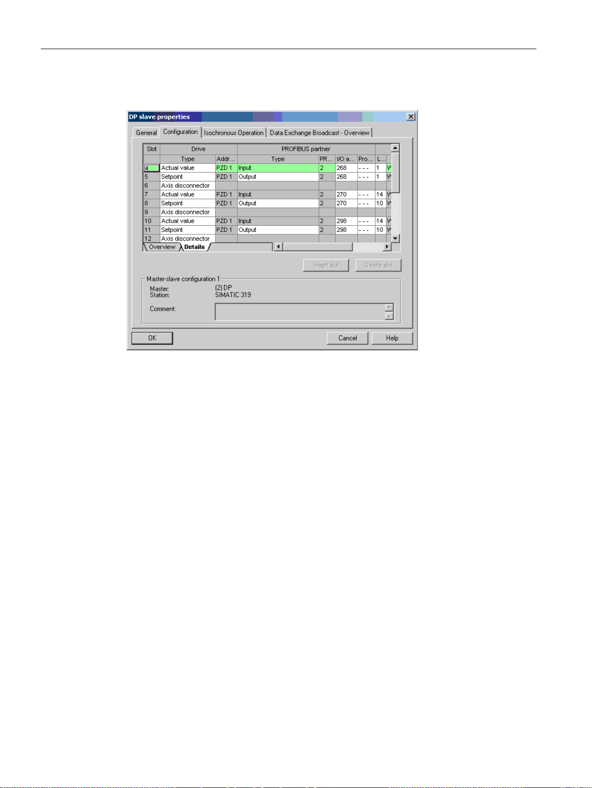
Communication via PROFIBUS DP
•
Object 1
•
Object 2
•
Object 3
etc.
4.1 General information about PROFIBUS
DP slave properties – details
Figure 4-3 Slave properties – details
The axis separator separates the objects in the telegram as follows:
Slots 4 and 5:
Slots 7 and 8:
Slots 10 and 11:
––> Active Infeed (A_INF)
––> SERVO 1
––> SERVO 2
Communication
84 Function Manual, 12/2018, 6SL3097-5BD00-0BP0
Page 87
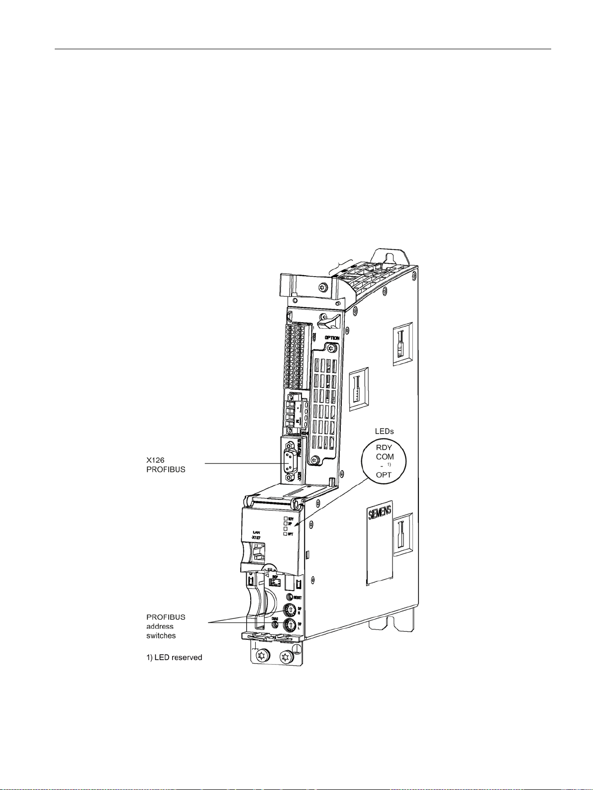
Communication via PROFIBUS DP
4.2 Commissioning PROFIBUS
4.2 Commissioning PROFIBUS
4.2.1 Setting the PROFIBUS interface
Interfaces and diagnostic LED
A PROFIBUS interface with LEDs and address switches is available as standard on the
CU320-2 DP Control Unit.
Figure 4-4 Interfaces and diagnostic LED
Communication
Function Manual, 12/2018, 6SL3097-5BD00-0BP0
85
Page 88
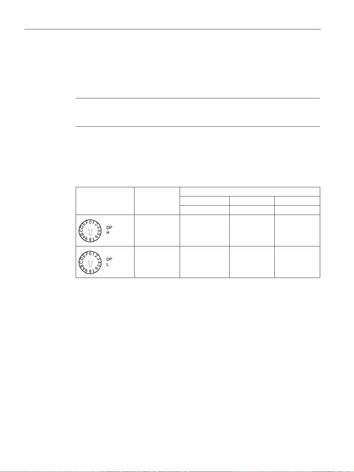
Communication via PROFIBUS DP
Note
A teleservice adapter can be connected to the PROFIBUS interface (X126) for remote
diagnostics purposes.
Rotary coding switch-
es
Significance
Examples
21
dec
35
dec
126
dec
15
hex
23
hex
7E
hex
4.2 Commissioning PROFIBUS
● PROFIBUS interface
The PROFIBUS is described in the "SINAMICS S120 Control Units and Supplementary
System Components Manual".
● PROFIBUS diagnostic LED
On the CU320-2 DP, the PROFIBUS address is set as a hexadecimal value via two rotary
(00
coding switches. You can set values from 0
dec
) to 127
hex
coding switch (H) you set the hexadecimal value for 16
0
switch (L) you set the hexadecimal value for 16
Table 4- 1 PROFIBUS address switch
.
1
(7F
dec
). At the upper rotary
hex
and at the lower rotary coding
1
16
= 16 1 2 7
0
16
= 1 5 3 E
Communication
86 Function Manual, 12/2018, 6SL3097-5BD00-0BP0
Page 89

Communication via PROFIBUS DP
Note
The rotary coding switches used to set the PROFIBUS address are located beneath the
cover.
Note
Address 126 is used for commissioning. Permitted PROFIBUS addresses are 1
When several Control Units are connected to a PROFIBUS line, you set the addresses
differently than for the factory setting. Each PROFIBUS address in a PROFIBUS line can
only be assigned once. Either set the PROFIBUS address in absolute terms using
coding switches
is not effective until POWER ON.
The currently set address of the rotary coding switch is displayed in parameter r2057.
Note
Only values from 1 to 12
are set, then the set value is interpreted as "0". If a value "0" or "127" is set, the value in
parameter p0918 defines the PROFIBUS address.
4.2 Commissioning PROFIBUS
Setting the PROFIBUS address
The factory setting for the rotary coding switches is 0
dec
(00
hex
).
There are two ways to set the PROFIBUS address:
1. Using the STARTER commissioning tool (parameter p0918)
– To set the bus address for a PROFIBUS node using STARTER, first set the rotary
code switches to 0
dec
(00
hex
) and/or 127
dec
(7F
hex
).
– Then set the address to a value from 1 to 126 using parameter p0918.
2. Using the PROFIBUS address switches on the Control Unit
– The address is set manually to values from 1 to 126 using the rotary coding switches.
In this case, parameter p0918 is only used to read the address.
... 126.
the rotary
– or selectively in parameter p0918. Each change made to the bus address
6 (7E
) are valid for PROFIBUS addressing. If values above 127
hex
Communication
Function Manual, 12/2018, 6SL3097-5BD00-0BP0
87
Page 90

Communication via PROFIBUS DP
4.2 Commissioning PROFIBUS
4.2.2 PROFIBUS interface in operation
Generic station description file
A generic station description file clearly and completely defines the properties of a
PROFIBUS slave.
The SINAMICS S GSD file contains among other things standard telegrams, free telegrams
and slave-to-slave telegrams for configuring slave-to-slave communication. With the aid of
these telegram parts and an axis separator, a telegram for the drive unit must be composed
for each drive object.
The GSD files can be found:
● On the Internet:
PROFINET I/O (https://support.industry.siemens.com/cs/ww/en/view/49217480) (GSDML
files)
PROFIBUS DP (https://support.industry.siemens.com/cs/ww/en/view/49216293) (GSD
files)
● On the CD/DVD of the Startdrive commissioning tool
● On the memory card in the directory:
\\SIEMENS\SINAMICS\DATA\CFG\
The integration of a GSD file in HW Config is covered in the SIMATIC documentation.
Suppliers of PROFIBUS components can provide their own bus configuration tool. The
operation of the respective bus configuration tool is described in the relevant documentation.
Note for commissioning for VIK-NAMUR
To be able to operate a SINAMICS drive as a VIK-NAMUR drive, standard telegram 20 must
be set and the VIK-NAMUR identification number activated via p2042 =1.
Device identification
Identification for individual slaves facilitates diagnostics and provides an overview of the
nodes on the PROFIBUS.
The information for each slave is stored in the following CU-specific parameter:
r0964[0...6] device identification
Bus terminating resistor and shielding
Reliable data transmission via PROFIBUS depends, amongst other things, on the setting of
the bus terminating resistors and the shielding of the PROFIBUS cables.
● Bus terminating resistor
The bus terminating resistors in the PROFIBUS plugs must be set as follows:
– First and last nodes in the line: Switch on terminating resistor
– Other nodes in the line: Switch off terminating resistor
● Shielding of the PROFIBUS cables
The cable shield must be connected in the plug through a large surface area at both ends
(see SINAMICS S120 Control Units and Supplementary System Components Manual).
Communication
88 Function Manual, 12/2018, 6SL3097-5BD00-0BP0
Page 91

Communication via PROFIBUS DP
Requirement
4.2 Commissioning PROFIBUS
4.2.3 Commissioning PROFIBUS
Preconditions and assumptions for commissioning
PROFIBUS slave
PROFIBUS master
• The PROFIBUS address to be set for the device application is known.
• The telegram type for each drive object is known by the application.
• The communication properties of the SINAMICS S120 slave must be availa-
ble in the master (GSD file or Drive ES slave OM).
Commissioning steps (example with SIMATIC S7)
1. Set the PROFIBUS address on the slave.
2. Set the telegram type on the slave.
3. Perform the following in HW Config:
– Connect the drive unit to PROFIBUS and assign the address.
– Set the telegram type.
The same telegram type as on the slave should be set for every drive object
exchanging process data via PROFIBUS.
The master can send more process data than the slave uses. A telegram with a larger
number of PZDs than assigned for the SINAMICS drive object can be configured on
the master.
The PZDs not supplied by the drive object are filled with zeros.
The setting "without PZD" can be defined on a node or object (e.g. infeed controlled
via terminals).
4. Assign the I/O addresses according to the user program.
Communication
Function Manual, 12/2018, 6SL3097-5BD00-0BP0
89
Page 92

Communication via PROFIBUS DP
Field
Value
Network parameter profile
DP
Communication partner address
PROFIBUS address of the drive unit
Field
Value
Name
Any
Controller
Any
REAL: for float
Area
DB
(data block number)
1 ... 65535
4.2 Commissioning PROFIBUS
4.2.4 Diagnostics options
The standard slave diagnostics can be read online in the HW config.
4.2.5 SIMATIC HMI addressing
You can use a SIMATIC HMI as a PROFIBUS master (master class 2) to access SINAMICS
directly. With respect to SIMATIC HMI, SINAMICS behaves like a SIMATIC S7. For
accessing drive parameters, the following applies:
● Parameter number = data block number
● Parameter sub-index = bit 0 ... 9 of data block offset
● Drive object number = bit 10 ... 15 of data block offset
Pro Tool and WinCC flexible
The SIMATIC HMI can be configured flexibly with "Pro Tool" or "WinCC flexible".
The following specific settings for drives must be observed when configuration is carried out
with Pro Tool or WinCC flexible.
Controllers: Protocol always "SIMATIC S7 - 300/400"
Table 4- 2 Additional parameters
Network parameter baud rate Any
Communication partner
slot/rack
Table 4- 3 Variables: "General" tab
Type Depending on the addressed parameter value,
Don’t care, 0
e.g.:
INT: for integer 16
DINT: for integer 32
WORD: for unsigned 16
DB
Communication
90 Function Manual, 12/2018, 6SL3097-5BD00-0BP0
Parameter number
Page 93

Communication via PROFIBUS DP
Field
Value
DBW = 1024 * drive object No. + sub-index
Acquisition cycle
Any
Number of elements
1
Decimal places
Any
Note
•
•
•
4.2 Commissioning PROFIBUS
DBB, DBW, DBD
(data block offset)
Length Not activated
Drive object No. and sub-index
bit 15 ... 10: Drive object No. 0 ... 63
bit 9 ... 0: Sub-index 0 ... 1023
or expressed differently
You can operate a SIMATIC HMI together with a drive unit independently of an existing
controller.
A basic "point-to-point" connection can only be established between two nodes (devices).
The "variable" HMI function can be used for drive units. Other functions cannot be used
(e.g. "messages" or "recipes").
Individual parameter values can be accessed. Entire arrays, descriptions, or texts cannot
be accessed.
Communication
Function Manual, 12/2018, 6SL3097-5BD00-0BP0
91
Page 94
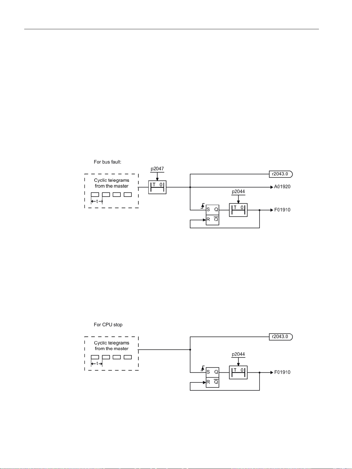
Communication via PROFIBUS DP
4.2 Commissioning PROFIBUS
4.2.6 Monitoring telegram failure
When monitoring the telegram failure, SINAMICS differentiates between two cases:
● Telegram failure with a bus fault
After a telegram failure and the additional monitoring time has elapsed (p2047), bit
r2043.0 is set to "1" and alarm A01920 is output. Binector output r2043.0 can be used for
a quick stop, for example.
Once the delay time p2044 has elapsed, fault F01910 is output. Fault F01910 triggers
fault response OFF2 (pulse inhibit) for the infeed and OFF3 (quick stop) for
SERVO/VECTOR. If no OFF response is to be triggered, the fault response can be
reparameterized accordingly.
Fault F01910 can be acknowledged immediately. The drive can then be operated even
without PROFIdrive.
Figure 4-5 Monitoring telegram failure with a bus fault
● Telegram failure with a CPU stop
After telegram failure, bit r2043.0 is set to "1". Binector output r2043.0 can be used for a
quick stop, for example.
Once the delay time p2044 has elapsed, fault F01910 is output. Fault F01910 triggers
fault response OFF2 (pulse inhibit) for the infeed and OFF3 (quick stop) for
SERVO/VECTOR. If no OFF response is to be triggered, the fault response can be
reparameterized accordingly.
Fault F01910 can be acknowledged immediately. The drive can then be operated even
without PROFIdrive.
Figure 4-6 Monitoring telegram failure for a CPU stop
Communication
92 Function Manual, 12/2018, 6SL3097-5BD00-0BP0
Page 95

Communication via PROFIBUS DP
CU
p2047
= 20 ms
A_INF
p2044
= 2 s
VECTOR
p2044
= 0 s
4.2 Commissioning PROFIBUS
Example: Quick stop at telegram failure
Assumption:
● A drive unit with an Active Line Module and a Single Motor Module.
● VECTOR mode is activated.
● After a ramp-down time (p1135) of two seconds, the drive is at a standstill.
Settings:
Sequence:
1. Following a telegram failure and once the additional monitoring time (p2047) has elapsed,
binector output r2043.0 of drive object CU switches to "1".
At the same time, alarm A01920 is output for the A_INF drive objects and alarm A01920
and fault F01910 are output for VECTOR.
2. When F01910 is output, an OFF3 is triggered for the drive.
3. After a two-second delay time (p2044), fault F01910 is output on the infeed and triggers
OFF2.
Communication
Function Manual, 12/2018, 6SL3097-5BD00-0BP0
93
Page 96
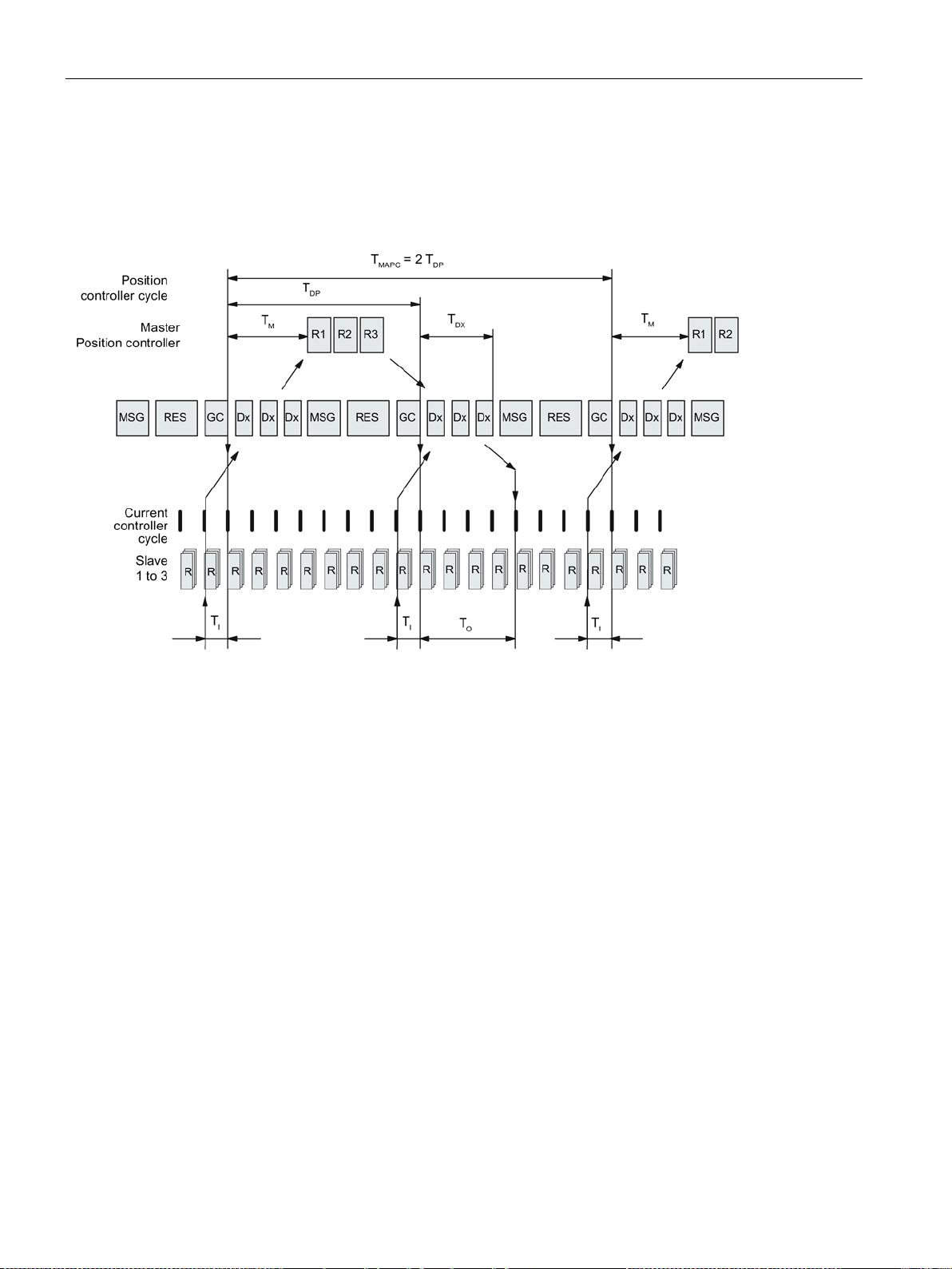
Communication via PROFIBUS DP
4.3 Motion Control with PROFIBUS
4.3 Motion Control with PROFIBUS
Motion control / isochronous drive coupling with PROFIBUS
Figure 4-7 Motion control / isochronous drive coupling with PROFIBUS, optimized cycle with T
Sequence of data transfer to closed-loop control system
1. The actual position value G1_XACT1 is read into at time T
and transferred to the master in the next cycle.
2. The closed-loop control of the master starts at time T
and uses the transferred actual value in the telegram.
3. In the next cycle, the master forwards the calculated setpoints to the slaves. The speed
setpoint command NSET_B is issued to the closed-loop control system at time T
the beginning of the cycle.
before the start of each cycle
I
after each position controller cycle
M
MAPC
= 2 ∙ TDP
after
O
Communication
94 Function Manual, 12/2018, 6SL3097-5BD00-0BP0
Page 97

Communication via PROFIBUS DP
Name
Limit value
Description
T
BASE_DP
250 µs
Time base for TDP
T
DP_MAX
= 32 ms
T
= integer multiple of TDP
T
BASE_IO
125 µs
Time base for TI, TO
This is the time at which the actual position value is captured before the start of
Does not apply to vector V/f.
object (SERVO/VECTOR) in the drive unit, minimum 125 µsec
available slaves.
T
-
PLL window
T
PLL_D
-
PLL delay time
GC Global Control Telegram (broadcast telegram)
slave 1 - n.
slave 1 - n on an acyclic basis.
RES
Reserve: "Active pause" until the isochronous cycle has expired
R Computation time, speed or position controller in the master or slave
Start of closed-loop master control
4.3 Motion Control with PROFIBUS
Designations and descriptions for motion control
Table 4- 4 Time settings and meanings
TDP TDP ≥ T
DP_MIN
≤ TDP ≤ T
T
DP_MIN
T
Master application cycle time
MAPC
DP_MAX
DP cycle time
T
= Dx + MSG + RES + GC
DP
T
= multiple integer ∙ T
DP
T
= 1 ms
DP_MIN
This is the time frame in which the master application generates new setpoints
(e.g. in the position controller cycle).
MAPC
TI T
≤ TI < TDP Time of actual value sensing
I_MIN
each cycle.
T
= integer multiple of T
I
T
corresponds to the longest current controller sampling time (p0115[0]) of
I_MIN
a drive object (SERVO/VECTOR) in the drive unit, minimum 125 µs.
TO TDX + T
≤ TO < TDP Time of setpoint transfer
O_MIN
This is the time at which the transferred setpoints (speed setpoint) are accepted by the closed-loop control system after the start of the cycle.
= integer multiple of T
T
O
T
corresponds to the longest speed controller cycle (p0115[1]) of a drive
O_MIN
TDX TDX < TDP Data exchange time
This is the time required within one cycle for transferring process data to all
BASE_DP
BASE_IO
BASE_IO
PLL_W
Dx Data_Exchange
This service is used to implement user data exchange between master and
MSG Acyclic service
This service is used to implement user data exchange between master and
TM Master time
Communication
Function Manual, 12/2018, 6SL3097-5BD00-0BP0
95
Page 98

Communication via PROFIBUS DP
Note
After T
switched on (POWER ON) or parameter p0972
Data
Time required [µs]
Basic load
300
Per slave
20
Per byte of user data
1.5
One additional class 2 master
500
4.3 Motion Control with PROFIBUS
Setting criteria for times
● Cycle (T
– T
must be set to the same value for all bus nodes.
DP
– T
> TDX and TDP > TO
DP
DP
● T
and TO
I
– Setting the times in T
position control loop.
– T
> TDX + T
O
● Settings and tuning can be done using a tool (e.g. HW Config in SIMATIC S7).
Minimum times for reserves
Table 4- 5 Minimum times for reserves
)
DP
has been changed on the PROFIBUS master, the drive system must be
= 1 (reset drive unit) must be set.
and TO as short as possible reduces the dead time in the
I
Omin
Communication
96 Function Manual, 12/2018, 6SL3097-5BD00-0BP0
Page 99

Communication via PROFIBUS DP
4.3 Motion Control with PROFIBUS
User data integrity
User data integrity is verified in both transfer directions (master <––> slave) by a sign-of-life
(4-bit counter).
The sign-of-life counters are incremented from 1 to 15 and then start again at an arbitrary
value between 1 and 15.
● Master sign-of-life
– STW2.12 ... STW2.15 are used for the master sign-of-life.
– The master sign-of-life counter is incremented on each master application cycle
(T
).
MAPC
– The number of tolerated master sign-of-life errors in succession (of an isochronous
motor) can be set via p0925
– p0925 = 65535 deactivates sign-of-life monitoring on the slave.
– Monitoring
The master sign-of-life is monitored on the slave and any sign-of-life errors are
evaluated accordingly.
The maximum number of tolerated master sign-of-life errors can be set via p0925.
If the number of tolerated sign-of-life errors in succession set in p0925 is exceeded,
the response is as follows:
– A corresponding message is output.
– The value zero is output as the slave sign-of-life.
– Synchronization with the master sign-of-life is started.
● Slave sign-of-life
– ZSW2.12 ... ZSW2.15 are used for the slave sign-of-life.
– The slave sign-of-life counter is incremented in each DP cycle (T
Example: SINAMICS vector drives with SIMOTION D4x5 and/or CX modules
To determine which cycles in the SINAMICS drive unit will be set after a project has been
downloaded, dependable cycle values should be initially set in HW Config.
The following settings and sequences are recommended:
1. T
= 3.0 ms (T
DP
2. T
= To = 1.5 ms (TI = time of actual value acquisition, To = time of setpoint transfer)
I
3. T
= 6.0 ms (T
MAPC
= DP cycle time)
DP
= master application cycle time)
MAPC
DP
).
After a successful download, all current and speed controller cycles are visible. These cycles
can be optimized in HW Config if necessary.
The cycles are set in HW Config under the DP slave properties of the SINAMICS drive unit
(slave, master e.g. SIMOTION D4x5) under the "Clock synchronization" tab.
Communication
Function Manual, 12/2018, 6SL3097-5BD00-0BP0
97
Page 100
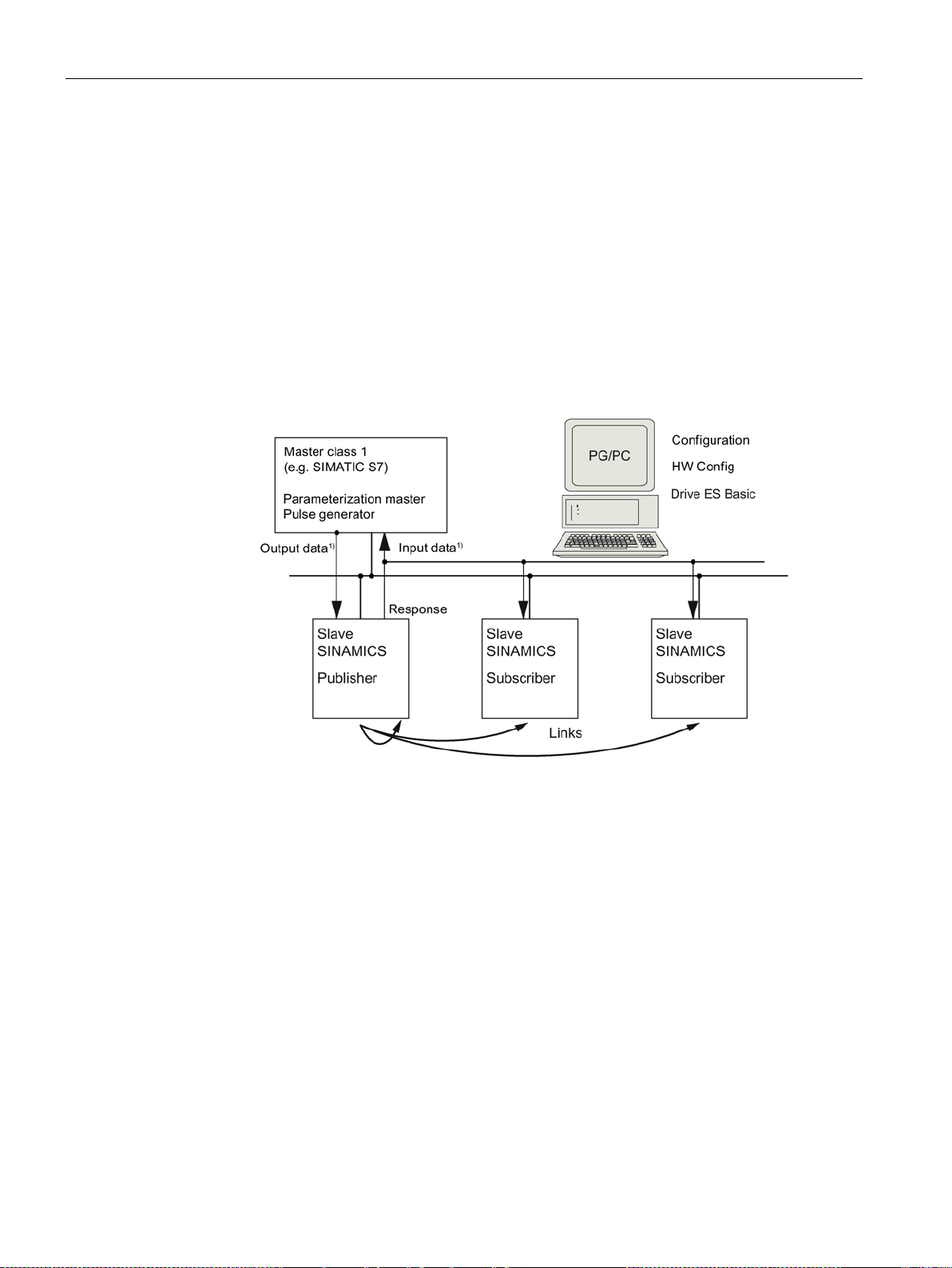
Communication via PROFIBUS DP
1)
From the perspective of the Class 1 master
4.4 Slave-to-slave communication
4.4 Slave-to-slave communication
For PROFIBUS DP, the master interrogates all of the slaves one after the other in a DP
cycle. In this case, the master transfers its output data (setpoints) to the particular slave and
receives as response the input data (actual values). Fast, distributed data transfer between
drives (slaves) is possible using the "slave-to-slave communication" function without direct
involvement from the master.
The following terms are used for the function described in this chapter:
● Slave-to-slave communication
● Data Exchange Broadcast (DXB.req)
● Slave-to-slave communication (is used in the following)
Figure 4-8 Slave-to-slave communication with the publisher-subscriber model
Publisher
With the "slave-to-slave communication" function, at least one slave must act as the
publisher.
The publisher is addressed by the master when the output data is transferred with a modified
layer 2 function code (DXB.req). The publisher then sends its input data for the master with a
broadcast telegram to all bus nodes.
Subscriber
The subscribers evaluate the broadcast telegrams, sent from the publishers, and use the
data which has been received as setpoints. These setpoints of the publisher are used, in
addition to the setpoints received from the master, corresponding to the configured telegram
structure (p0922).
Communication
98 Function Manual, 12/2018, 6SL3097-5BD00-0BP0
 Loading...