

Page 1

Answers for industry.
0HGLXP9ROWDJH9DULDEOH)UHTXHQF\'ULYH
6,1$0,&63(5)(&7+$5021<*+
1;*SUR&RPPXQLFDWLRQ
)XQFWLRQ0DQXDOy$(
SINAMICS PERFECT HARMONY GH180
$%
Page 2

Page 3

NXGpro Communication
Introduction
1
Function Manual
Safety notes
Modbus Communication
Modbus Ethernet
Communication
Ethernet / IP Communication
Profibus Communication
ProfiDrive Communication
DeviceNet (Profile 12)
Communication
2
3
4
5
6
7
8
ControlNet Communication
Menu Parameter Pick List IDs
Output Data IDs
Display Network Monitor
External Modem
Parameter Read/Write
Multiplexer (MUX) Data
Registers
9
A
B
C
D
E
F
AB
A5E33486415A
Internal Drive Network
List of abbreviations
G
H
Page 4
Legal information
Warning notice system
This manual contains notices you have to observe in order to ensure your personal safety, as well as to prevent
damage to property. The notices referring to your personal safety are highlighted in the manual by a safety alert
symbol, notices referring only to property damage have no safety alert symbol. These notices shown below are
graded according to the degree of danger.
DANGER
indicates that death or severe personal injury will result if proper precautions are not taken.
WARNING
indicates that death or severe personal injury may result if proper precautions are not taken.
CAUTION
indicates that minor personal injury can result if proper precautions are not taken.
NOTICE
indicates that property damage can result if proper precautions are not taken.
If more than one degree of danger is present, the warning notice representing the highest degree of danger will be
used. A notice warning of injury to persons with a safety alert symbol may also include a warning relating to property
damage.
Qualified Personnel
The product/system described in this documentation may be operated only by personnel qualified for the specific
task in accordance with the relevant documentation, in particular its warning notices and safety instructions. Qualified
personnel are those who, based on their training and experience, are capable of identifying risks and avoiding
potential hazards when working with these products/systems.
Proper use of Siemens products
Note the following:
WARNING
Siemens products may only be used for the applications described in the catalog and in the relevant technical
documentation. If products and components from other manufacturers are used, these must be recommended or
approved by Siemens. Proper transport, storage, installation, assembly, commissioning, operation and
maintenance are required to ensure that the products operate safely and without any problems. The permissible
ambient conditions must be complied with. The information in the relevant documentation must be observed.
Trademarks
All names identified by ® are registered trademarks of Siemens AG. The remaining trademarks in this publication
may be trademarks whose use by third parties for their own purposes could violate the rights of the owner.
Disclaimer of Liability
We have reviewed the contents of this publication to ensure consistency with the hardware and software described.
Since variance cannot be precluded entirely, we cannot guarantee full consistency. However, the information in
this publication is reviewed regularly and any necessary corrections are included in subsequent editions.
Siemens AG
Division Process Industries and Drives
Postfach 48 48
90026 NÜRNBERG
GERMANY
A5E33486415A
Ⓟ 08/2015 Subject to change
Copyright © Siemens AG 2014 - 2015.
All rights reserved
Page 5

Table of contents
1 Introduction.................................................................................................................................................17
1.1 Communication Overview......................................................................................................18
1.2 Remote Capabilities...............................................................................................................20
1.3 RS232 Port.............................................................................................................................21
1.4 Optional Hardware requirement for Dual Networks...............................................................22
1.5 Entering Parameter IDs..........................................................................................................23
2 Safety notes................................................................................................................................................25
2.1 General Safety Information....................................................................................................25
2.2 Safety Concept.......................................................................................................................26
2.3 Observing the Five Safety Rules............................................................................................27
2.4 Safety Information and Warnings...........................................................................................28
2.5 ESD-sensitive Components...................................................................................................30
2.6 Electromagnetic Fields in Electrical Power Engineering Installations ...................................32
2.7 Security Information...............................................................................................................33
3 Modbus Communication.............................................................................................................................35
3.1 Description.............................................................................................................................36
3.1.1 Network Configuration Options..............................................................................................36
3.1.2 Siemens Modbus Module.......................................................................................................37
3.2 Software Programming..........................................................................................................40
3.2.1 Programmable Inputs to the Drive.........................................................................................40
3.2.2 Programmable Outputs from the Drive..................................................................................42
3.3 Parameter Assignment/Addressing........................................................................................44
3.3.1 Correspondence between Drive Parameter ID and Communication Protocol Address.........44
3.3.2 Parameter Tables...................................................................................................................45
3.3.3 Pick List Variable Tables........................................................................................................50
3.4 Planning/Configuring..............................................................................................................56
3.4.1 Fast Setup: Control the drive using the default configuration................................................56
3.4.2 Fast Setup: Monitor drive status and speed feedback...........................................................57
3.4.3 Fast Setup: Send a motor speed setting to the drive.............................................................59
3.4.4 Fast Setup: Control the drive using user-defined bits controlled by the SOP........................59
3.4.5 Network Setup Procedure......................................................................................................60
3.4.6 Network Status Detection Setup............................................................................................61
3.4.7 Setup Example.......................................................................................................................62
3.5 Functions................................................................................................................................64
3.5.1 Read Coil Command (0x01)...................................................................................................64
3.5.2 Read Holding Registers Command (0x03)............................................................................65
3.5.3 Write Multiple Coils Command (0x0F)...................................................................................67
NXGpro Communication
Function Manual, AB, A5E33486415A 5
Page 6

Table of contents
3.5.4 Write Single Input Register Command (0x06)........................................................................68
3.5.5 Loop Back Diagnostic Test Command (0x08)........................................................................69
3.5.6 Write Multiple Input Registers Command (0x10)...................................................................70
4 Modbus Ethernet Communication..............................................................................................................73
4.1 Description.............................................................................................................................74
4.1.1 Network Configuration Options..............................................................................................74
4.1.2 Anybus Modbus Ethernet Module..........................................................................................75
4.2 Software Programming..........................................................................................................77
4.2.1 Programmable Inputs to the Drive.........................................................................................77
4.2.2 Programmable Outputs from the drive...................................................................................79
4.3 Parameter Assignment/Addressing........................................................................................81
4.3.1 Correspondence between Drive Parameter ID and Communication Protocol Address.........81
4.3.2 Parameter Tables...................................................................................................................83
4.3.3 Pick List Variable Tables........................................................................................................86
4.4 Planning/Configuring..............................................................................................................92
4.4.1 Fast Setup: Control the drive using the default configuration................................................92
4.4.2 Fast Setup: Monitor drive status and speed feedback...........................................................93
4.4.3 Fast Setup: Send a motor speed setting to the drive.............................................................95
4.4.4 Fast Setup: Control the drive using user-defined bits controlled by the SOP........................95
4.4.5 Network Interfaces ................................................................................................................96
4.4.6 Network Setup Procedure......................................................................................................98
4.4.7 Network Status Detection Setup............................................................................................99
4.4.8 Setup Example.....................................................................................................................100
4.5 Functions..............................................................................................................................102
4.5.1 Read Holding Registers Command (0x03)..........................................................................102
4.5.2 Write Single Input Register Command (0x06)......................................................................104
4.5.3 Write Multiple Input Registers Command (0x10).................................................................105
5 Ethernet / IP Communication....................................................................................................................107
5.1 AnyBus Ethernet/IP Module.................................................................................................107
5.2 Description...........................................................................................................................109
5.2.1 Ethernet/IP Description .......................................................................................................109
5.2.2 Network Configuration Options............................................................................................109
5.2.3 AnyBus Ethernet/IP Module.................................................................................................110
5.3 Software Programming........................................................................................................112
5.3.1 Flags available to the SOP ..................................................................................................112
5.3.2 Programmable Inputs to the drive .......................................................................................112
5.3.3 Programmable Outputs from the drive.................................................................................114
5.4 Parameter Assignment/Addressing......................................................................................116
5.4.1 Overview: Parameter assignment/addressing ....................................................................116
5.4.2 Correspondence between Drive Parameter ID and Communication Protocol Address ......116
5.4.3 Parameter Tables ................................................................................................................117
5.4.4 Pick List Variable Tables......................................................................................................120
5.5 Planning/Configuring............................................................................................................126
5.5.1 Overview: planning/configuring ...........................................................................................126
5.5.2 Fast Setup: Control the drive using the default configuration..............................................126
5.5.3 Fast Setup: Monitor drive status and speed feedback ........................................................127
NXGpro Communication
6 Function Manual, AB, A5E33486415A
Page 7

Table of contents
5.5.4 Fast Setup: Send a motor speed setting to the drive ..........................................................129
5.5.5 Fast Setup: Control the drive using user-defined bits controlled by the SOP .....................129
5.5.6 Network Interfaces ..............................................................................................................130
5.5.7 PLC Setup using EDS files .................................................................................................130
5.5.8 Network Status Detection Setup..........................................................................................131
5.5.9 Network Setup Procedure....................................................................................................131
5.5.10 Setup Example.....................................................................................................................132
6 Profibus Communication..........................................................................................................................135
6.1 Description...........................................................................................................................136
6.1.1 Anybus Profibus Module......................................................................................................137
6.2 Software Programming........................................................................................................140
6.2.1 Programmable Inputs to the Drive.......................................................................................140
6.2.2 Programmable Outputs from the Drive................................................................................142
6.3 Parameter Assignment/Addressing......................................................................................144
6.3.1 Correspondence between Drive Parameter ID and Communication Protocol Address.......144
6.3.2 Parameter Tables.................................................................................................................146
6.3.3 Pick List Variable Tables......................................................................................................149
6.4 Planning/Configuring............................................................................................................155
6.4.1 Fast Setup: Control the drive using the default configuration..............................................155
6.4.2 Fast Setup: Monitor drive status and speed feedback.........................................................156
6.4.3 Fast Setup: Send a motor speed setting to the drive...........................................................158
6.4.4 Fast Setup: Control the drive using user-defined bits controlled by the SOP......................158
6.4.5 PLC Setup using GSD files..................................................................................................159
6.4.6 Network Setup Procedure....................................................................................................159
6.4.7 Network Status (auto detect)................................................................................................161
6.4.8 Setup Example.....................................................................................................................161
7 ProfiDrive Communication........................................................................................................................163
7.1 Description...........................................................................................................................164
7.1.1 Anybus Profibus DP-V1 IM Module......................................................................................165
7.2 Parameter Assignment/Addressing......................................................................................168
7.2.1 Correspondence between Drive Parameter ID and Communication Protocol Address.......168
7.2.2 Parameter Tables.................................................................................................................170
7.2.3 Pick List Variable Tables......................................................................................................173
7.2.4 Telegram Data Tables..........................................................................................................178
7.3 Planning/Configuring............................................................................................................184
7.3.1 Fast Setup: Control the drive using the default configuration..............................................185
7.3.2 PLC Setup using GSD files..................................................................................................185
7.3.3 Network Setup Procedure....................................................................................................186
7.3.4 Network Status (auto detect)................................................................................................187
8 DeviceNet (Profile 12) Communication....................................................................................................189
8.1 Description...........................................................................................................................190
8.1.1 Anybus DeviceNet Module...................................................................................................191
8.2 Software Programming........................................................................................................194
8.2.1 Programmable Inputs to the Drive.......................................................................................194
8.2.2 Programmable Outputs from the Drive................................................................................196
8.3 Parameter Assignment/Addressing......................................................................................198
NXGpro Communication
Function Manual, AB, A5E33486415A 7
Page 8

Table of contents
8.3.1 Correspondence between Drive Parameter ID and Communication Protocol Address.......198
8.3.2 Parameter Tables.................................................................................................................199
8.3.3 Pick List Variable Tables......................................................................................................202
8.4 Planning/Configuring............................................................................................................208
8.4.1 Fast Setup: Control the drive using the default configuration..............................................208
8.4.2 Fast Setup: Monitor drive status and speed feedback.........................................................209
8.4.3 Fast Setup: Send a motor speed setting to the drive...........................................................211
8.4.4 Fast Setup: Control the drive using user-defined bits controlled by the SOP......................211
8.4.5 PLC Setup using EDS files..................................................................................................212
8.4.6 Network Setup Procedure....................................................................................................212
8.4.7 Network Status (auto detect)................................................................................................214
8.4.8 Setup Example.....................................................................................................................214
9 ControlNet Communication......................................................................................................................217
9.1 Description...........................................................................................................................218
9.1.1 Anybus ControlNet Module..................................................................................................218
9.2 Software Programming........................................................................................................220
9.2.1 Programmable Inputs to the Drive.......................................................................................220
9.2.2 Programmable Outputs from the Drive................................................................................222
9.3 Parameter Assignment/Addressing......................................................................................224
9.3.1 Correspondence between Drive Parameter ID and Communication Protocol Address.......224
9.3.2 Parameter Tables.................................................................................................................225
9.3.3 Pick List Variable Tables......................................................................................................228
9.4 Planning/Configuring............................................................................................................234
9.4.1 Fast Setup: Control the drive using the default configuration..............................................234
9.4.2 Fast Setup: Monitor drive status and speed feedback.........................................................235
9.4.3 Fast Setup: Send a motor speed setting to the drive...........................................................237
9.4.4 Fast Setup: Control the drive using user-defined bits controlled by the SOP......................237
9.4.5 PLC Setup using EDS files..................................................................................................238
9.4.6 Network Setup Procedure....................................................................................................238
9.4.7 Network Status (auto detect)................................................................................................240
9.4.8 Setup Example.....................................................................................................................240
A Menu Parameter Pick List IDs..................................................................................................................243
A.1 Internal Analog Outputs.......................................................................................................260
A.2 Internal Test Points..............................................................................................................262
A.3 External Analog Inputs.........................................................................................................266
A.4 External Analog Outputs......................................................................................................267
A.5 Comparators........................................................................................................................269
A.6 Historic Log Variables..........................................................................................................270
A.7 Meter Status Variables.........................................................................................................271
A.8 To Drive Communication......................................................................................................273
A.9 From Drive Communication.................................................................................................275
B Output Data IDs........................................................................................................................................277
B.1 Output data IDs....................................................................................................................277
NXGpro Communication
8 Function Manual, AB, A5E33486415A
Page 9

Table of contents
C Display Network Monitor...........................................................................................................................299
D External Modem.......................................................................................................................................301
E Parameter Read/Write..............................................................................................................................303
E.1 Setting up the PTD and PFD registers.................................................................................304
E.2 Defining the PFD Registers..................................................................................................305
E.3 Defining the PTD Registers..................................................................................................306
E.4 PLC handshaking procedure for parameter read/write........................................................309
F Multiplexer (MUX) Data Registers............................................................................................................311
G Internal Drive Network..............................................................................................................................313
H List of abbreviations..................................................................................................................................317
Glossary...................................................................................................................................................323
Index.........................................................................................................................................................333
Tables
Table 3-1 Status Indicator Descriptions.......................................................................................................39
Table 3-2 Jumper to enable/disable Termination Resistor..........................................................................39
Table 3-3 Network 1 and 2: Fixed Register Bits .........................................................................................40
Table 3-4 Network 1: Programmable input bits (parameter ID 9603-9664).................................................41
Table 3-5 Network 2: Programmable input bits (parameter ID 9703-9764).................................................41
Table 3-6 Network 1: Programmable output bits (parameter ID 9403-9464)..............................................42
Table 3-7 Network 2: Programmable output bits (parameter ID 9503-9564)..............................................42
Table 3-8 Correspondence between Drive Parameter ID and Modbus Address........................................44
Table 3-9 Network Control Menu (9943).....................................................................................................45
Table 3-10 Network 1 to 2 Register Copy (9946)..........................................................................................45
Table 3-11 Network 1: Configure Menu (9900).............................................................................................46
Table 3-12 Network 1: Configure Parameters Menu (9902)..........................................................................46
Table 3-13 Network 1: Register Data from Drive Menu (9400).....................................................................47
Table 3-14 Network 1: Register Data to Drive Menu (9600).........................................................................47
Table 3-15 Network 2: Configure Menu (9914).............................................................................................47
Table 3-16 Network 2: Configure Parameters Menu (9916)..........................................................................48
Table 3-17 Network 2: Register Data from Drive Menu (9500).....................................................................48
Table 3-18 Network 2: Register Data to Drive Menu (9700).........................................................................49
Table 3-19 Data from Drive Pick List Variables.............................................................................................50
Table 3-20 Data to Drive Pick List Variables.................................................................................................53
Table 3-21 Default definitions of Fixed Register Bits.....................................................................................56
Table 3-22 Default definitions of General Status Bits....................................................................................58
Table 3-23 Completed Settings for Given Example......................................................................................63
NXGpro Communication
Function Manual, AB, A5E33486415A 9
Page 10

Table of contents
Table 3-24 Read Coils Request (TX) to Master............................................................................................64
Table 3-25 Read Coils Response (RX) from Master.....................................................................................65
Table 3-26 Read Holding Registers Request (TX) from Master....................................................................66
Table 3-27 Read Holding Registers Response (RX) from Drive...................................................................66
Table 3-28 Write Multiple Coils Request (TX) to Master...............................................................................67
Table 3-29 Write Multiple Coils Response (RX) from Master........................................................................68
Table 3-30 Write Input Register Request (TX) from Master..........................................................................69
Table 3-31 Write Multiple Input Registers Request (TX) from Master ..........................................................70
Table 3-32 Write Multiple Input Registers Response (RX) from Drive..........................................................70
Table 4-1 Status Indicator Table.................................................................................................................76
Table 4-2 Network 1 and 2: Fixed Register Bits .........................................................................................77
Table 4-3 Network 1: Programmable input bits (parameter ID 9603-9664).................................................78
Table 4-4 Network 2: Programmable input bits (parameter ID 9703-9764).................................................78
Table 4-5 Network 1: Programmable output bits (parameter ID 9403-9464)..............................................79
Table 4-6 Network 2: Programmable output bits (parameter ID 9503-9564)..............................................79
Table 4-7 Correspondence between Drive Parameter ID and Modbus Address........................................82
Table 4-8 Network Control Menu (9943).....................................................................................................83
Table 4-9 Network 1 to 2 Register Copy (9946)..........................................................................................83
Table 4-10 Network 1: Configure Menu (9900).............................................................................................83
Table 4-11 Network 1: Configure Parameters Menu (9902)..........................................................................84
Table 4-12 Network 1: TCP/IP Setup Menu (9300) when "Ethernet Modbus Type" (9906) is set to
"Internal CPU" 1...........................................................................................................................84
Table 4-13 Network 1: TCP/IP Setup Menu (9902) when "Ethernet Modbus Type" (9906) is set to
"Anybus Module"
1,2
......................................................................................................................84
Table 4-14 Network 1: Register Data from Drive Menu (9400).....................................................................84
Table 4-15 Network 1: Register Data to Drive Menu (9600).........................................................................85
Table 4-16 Network 2: Configure Menu (9914).............................................................................................85
Table 4-17 Network 2: Configure Parameters Menu (9916)..........................................................................85
Table 4-18 Network 2: Register Data from Drive Menu (9500).....................................................................86
Table 4-19 Network 2: Register Data to Drive Menu (9700).........................................................................86
Table 4-20 Data from Drive Pick List Variables.............................................................................................86
Table 4-21 Data to Drive Pick List Variables.................................................................................................90
Table 4-22 Default definitions of Fixed Register Bits.....................................................................................92
Table 4-23 Default definitions of General Status Bits....................................................................................94
Table 4-24 Completed Settings for Given Example....................................................................................101
Table 4-25 Read Holding Registers Request (TX) from Master..................................................................103
Table 4-26 Read Holding Registers Response (RX) from Drive.................................................................103
Table 4-27 Write Input Register Request (TX) from Master........................................................................104
Table 4-28 Write Multiple Input Registers Request (TX) from Master ........................................................105
Table 4-29 Write Multiple Input Registers Response (RX) from Drive........................................................106
NXGpro Communication
10 Function Manual, AB, A5E33486415A
Page 11

Table of contents
Table 5-1 Network 1 and 2: Fixed Register Bits .......................................................................................112
Table 5-2 Network 1: Programmable input bits (parameter ID 9603-9664)...............................................113
Table 5-3 Network 2: Programmable input bits (parameter ID 9703-9764)...............................................113
Table 5-4 Network 1: Programmable output bits (parameter ID 9403-9464)............................................114
Table 5-5 Network 2: Programmable output bits (parameter ID 9503-9564)............................................114
Table 5-6 Correspondence between Drive Parameter ID and Modbus Address......................................116
Table 5-7 Network Control Menu (9943)...................................................................................................117
Table 5-8 Network 1 to 2 Register Copy (9946)........................................................................................117
Table 5-9 Network 1: Configure Menu (9900)...........................................................................................118
Table 5-10 Network 1: Configure Parameters Menu (9902)........................................................................118
Table 5-11 Network 1: Register Data from Drive Menu (9400)...................................................................118
Table 5-12 Network 1: Register Data to Drive Menu (9600).......................................................................119
Table 5-13 Network 2: Configure Menu (9914)...........................................................................................119
Table 5-14 Network 2: Configure Parameters Menu (9916)........................................................................119
Table 5-15 Network 2: Register Data from Drive Menu (9500)...................................................................120
Table 5-16 Network 2: Register Data to Drive Menu (9700).......................................................................120
Table 5-17 Data from Drive Pick List Variables...........................................................................................120
Table 5-18 Data to Drive Pick List Variables...............................................................................................124
Table 5-19 Default definitions of Fixed Register Bits...................................................................................127
Table 5-20 Default definitions of General Status Bits..................................................................................128
Table 5-21 Completed Settings for Given Example....................................................................................133
Table 6-1 Status Indicator Descriptions.....................................................................................................138
Table 6-2 Network 1 and 2: Fixed Register Bits .......................................................................................140
Table 6-3 Network 1: Programmable input bits (parameter ID 9603-9664)...............................................141
Table 6-4 Network 2: Programmable input bits (parameter ID 9703-9764)...............................................141
Table 6-5 Network 1: Programmable output bits (parameter ID 9403-9464)............................................142
Table 6-6 Network 2: Programmable output bits (parameter ID 9503-9564)............................................142
Table 6-7 Correspondence between Drive Parameter ID and Profibus Network Data.............................145
Table 6-8 Network Control Menu (9943)...................................................................................................146
Table 6-9 Network 1 to 2 Register Copy (9946)........................................................................................146
Table 6-10 Network 1: Configure Menu (9900)...........................................................................................146
Table 6-11 Network 1: Configure Parameters Menu (9902)........................................................................146
Table 6-12 Network 1: Register Data from Drive Menu (9400)...................................................................147
Table 6-13 Network 1: Register Data to Drive Menu (9600).......................................................................147
Table 6-14 Network 2: Configure Menu (9914)...........................................................................................147
Table 6-15 Network 2: Configure Parameters Menu (9916)........................................................................148
Table 6-16 Network 2: Register Data from Drive Menu (9500)...................................................................148
Table 6-17 Network 2: Register Data to Drive Menu (9700).......................................................................148
Table 6-18 Data from Drive Pick List Variables...........................................................................................149
NXGpro Communication
Function Manual, AB, A5E33486415A 11
Page 12

Table of contents
Table 6-19 Data to Drive Pick List Variables...............................................................................................152
Table 6-20 Default definitions of Fixed Register Bits...................................................................................155
Table 6-21 Default definitions of General Status Bits..................................................................................157
Table 6-22 Completed Settings for Given Example....................................................................................162
Table 7-1 Status Indicator Descriptions.....................................................................................................166
Table 7-2 Correspondence between Drive Parameter ID and ProfiDrive Telegram.................................169
Table 7-3 Network 1 to 2 Register Copy (9946)........................................................................................170
Table 7-4 Network 1: Configure Menu (9900)...........................................................................................170
Table 7-5 Network 1: Configure Parameters Menu (9902)........................................................................170
Table 7-6 Network 1: Register Data from Drive Menu (9400)...................................................................171
Table 7-7 Network 1: Register Data to Drive Menu (9600).......................................................................171
Table 7-8 Network 2: Configure Menu (9914)...........................................................................................171
Table 7-9 Network 2: Configure Parameters Menu (9916)........................................................................172
Table 7-10 Network 2: Register Data from Drive Menu (9500)...................................................................172
Table 7-11 Network 2: Register Data to Drive Menu (9700).......................................................................172
Table 7-12 Data from Drive Pick List Variables...........................................................................................173
Table 7-13 Data to Drive Pick List Variables...............................................................................................176
Table 7-14 Supported ProfiDrive Telegrams...............................................................................................178
Table 7-15 Telegram 1................................................................................................................................178
Table 7-16 Telegram 2................................................................................................................................178
Table 7-17 Telegram 20..............................................................................................................................178
Table 7-18 Telegram 352............................................................................................................................179
Table 7-19 Telegram 999............................................................................................................................179
Table 7-20 Telegram 998............................................................................................................................179
Table 7-21 Data from Drive Signals............................................................................................................180
Table 7-22 Data to Drive Signals.................................................................................................................181
Table 7-23 ZSW1 Signal: Status Bits..........................................................................................................181
Table 7-24 STW1 Signal: Control Bits.........................................................................................................182
Table 7-25 Supported Parameters..............................................................................................................182
Table 8-1 Status Indicator Descriptions.....................................................................................................193
Table 8-2 Network 1 and 2: Fixed Register Bits .......................................................................................194
Table 8-3 Network 1: Programmable input bits (parameter ID 9603-9664)...............................................195
Table 8-4 Network 2: Programmable input bits (parameter ID 9703-9764)...............................................195
Table 8-5 Network 1: Programmable output bits (parameter ID 9403-9464)............................................196
Table 8-6 Network 2: Programmable output bits (parameter ID 9503-9564)............................................196
Table 8-7 Correspondence between Drive Parameter ID and DeviceNet Network Data..........................199
Table 8-8 Network Control Menu (9943)...................................................................................................199
Table 8-9 Network 1 to 2 Register Copy (9946)........................................................................................200
Table 8-10 Network 1: Configure Menu (9900)...........................................................................................200
NXGpro Communication
12 Function Manual, AB, A5E33486415A
Page 13

Table of contents
Table 8-11 Network 1: Configure Parameters Menu (9902)........................................................................200
Table 8-12 Network 1: Register Data from Drive Menu (9400)...................................................................201
Table 8-13 Network 1: Register Data to Drive Menu (9600).......................................................................201
Table 8-14 Network 2: Configure Menu (9914)...........................................................................................201
Table 8-15 Network 2: Configure Parameters Menu (9916)........................................................................201
Table 8-16 Network 2: Register Data from Drive Menu (9500)...................................................................202
Table 8-17 Network 2: Register Data to Drive Menu (9700).......................................................................202
Table 8-18 Data from Drive Pick List Variables...........................................................................................202
Table 8-19 Data to Drive Pick List Variables...............................................................................................206
Table 8-20 Default definitions of Fixed Register Bits...................................................................................208
Table 8-21 Default definitions of General Status Bits..................................................................................210
Table 8-22 Completed Settings for Given Example....................................................................................215
Table 9-1 Status Indicator Descriptions.....................................................................................................219
Table 9-2 Network 1 and 2: Fixed Register Bits .......................................................................................220
Table 9-3 Network 1: Programmable input bits (parameter ID 9603-9664)...............................................221
Table 9-4 Network 2: Programmable input bits (parameter ID 9703-9764)...............................................221
Table 9-5 Network 1: Programmable output bits (parameter ID 9403-9464)............................................222
Table 9-6 Network 2: Programmable output bits (parameter ID 9503-9564)............................................222
Table 9-7 Correspondence between Drive Parameter ID and ControlNet Network Data.........................225
Table 9-8 Network Control Menu (9943)...................................................................................................225
Table 9-9 Network 1 to 2 Register Copy (9946)........................................................................................225
Table 9-10 Network 1: Configure Menu (9900)...........................................................................................226
Table 9-11 Network 1: Configure Parameters Menu (9902)........................................................................226
Table 9-12 Network 1: Register Data from Drive Menu (9400)...................................................................226
Table 9-13 Network 1: Register Data to Drive Menu (9600).......................................................................227
Table 9-14 Network 2: Configure Menu (9914)...........................................................................................227
Table 9-15 Network 2: Configure Parameters Menu (9916)........................................................................227
Table 9-16 Network 2: Register Data from Drive Menu (9500)...................................................................228
Table 9-17 Network 2: Register Data to Drive Menu (9700).......................................................................228
Table 9-18 Data from Drive Pick List Variables...........................................................................................228
Table 9-19 Data to Drive Pick List Variables...............................................................................................232
Table 9-20 Default definitions of Fixed Register Bits...................................................................................234
Table 9-21 Default definitions of General Status Bits..................................................................................236
Table 9-22 Completed Settings for Given Example....................................................................................241
Table A-1 Menu Parameter Pick List IDs...................................................................................................243
Table B-1 General Data Register Assignments.........................................................................................278
Table B-2 Serial Flags...............................................................................................................................279
Table B-3 Network Output Flags................................................................................................................280
Table B-4 WAGO™ Input and Output Flags..............................................................................................280
NXGpro Communication
Function Manual, AB, A5E33486415A 13
Page 14

Table of contents
Table B-5 Internal Digital Inputs and Outputs............................................................................................281
Table B-6 Cell Temperature.......................................................................................................................281
Table B-7 Number of Faults and Alarms....................................................................................................282
Table B-8 Fault Word 1..............................................................................................................................283
Table B-9 Fault Word 2..............................................................................................................................285
Table B-10 Fault Word 3..............................................................................................................................287
Table B-11 Fault Word 4..............................................................................................................................288
Table B-12 Fault/Alarm Flags 1...................................................................................................................289
Table B-13 Fault/Alarm Flags 2...................................................................................................................291
Table B-14 Fault/Alarm Flags 3...................................................................................................................292
Table B-15 Fault/Alarm Flags 4...................................................................................................................292
Table B-16 Fault/Alarm Enable Flags..........................................................................................................293
Table B-17 Fatal Fault Flags........................................................................................................................294
Table B-18 Analog Input Read Registers....................................................................................................294
Table B-19 Active Cells Read Registers......................................................................................................294
Table B-20 Cell Status.................................................................................................................................295
Table B-21 Cell Bypass Status....................................................................................................................295
Table B-22 Performance Data.....................................................................................................................296
Table B-23 Parameter Read/Write Data......................................................................................................296
Table B-24 Parallel Drive Data....................................................................................................................296
Table B-25 Voltage/Current Data.................................................................................................................297
Table B-26 SilcoGraph Data........................................................................................................................298
Table B-27 Shared Memory Data................................................................................................................298
Table B-28 Internal Network Data................................................................................................................298
Table B-29 Register to Drive Manual IDs....................................................................................................298
Table D-1 Serial Port Setup Menu (9010) ...............................................................................................301
Table E-1 Contents of PFD Registers 1 to 4..............................................................................................305
Table E-2 Contents of PTD Registers 1 to 4..............................................................................................306
Table E-3 Available ID Function Commands.............................................................................................307
Table G-1 SOP Output Flags.....................................................................................................................314
Table G-2 SOP Input Flags........................................................................................................................314
Table H-1 Commonly Used Abbreviations.................................................................................................317
Figures
Figure 1-1 NXGpro Control...........................................................................................................................19
Figure 2-1 ESD Protective Measures...........................................................................................................31
Figure 3-1 Typical 2-wire Modbus Communication Connection...................................................................37
Figure 3-2 Siemens Modbus Module............................................................................................................38
NXGpro Communication
14 Function Manual, AB, A5E33486415A
Page 15

Table of contents
Figure 3-3 RS485 Pin Assignments..............................................................................................................38
Figure 4-1 Anybus Ethernet Module.............................................................................................................75
Figure 4-2 Status Indicators..........................................................................................................................75
Figure 4-3 Direct Modbus Ethernet Communication Connection.................................................................96
Figure 4-4 Network Modbus™ Ethernet Communication Connection..........................................................97
Figure 5-1 Anybus™ Ethernet Module.......................................................................................................107
Figure 5-2 Status Indicators........................................................................................................................107
Figure 5-3 Anybus™ Ethernet Module.......................................................................................................110
Figure 5-4 Status Indicators........................................................................................................................110
Figure 5-5 Ethernet I/P Communication Connection..................................................................................130
Figure 6-1 Anybus Profibus Module...........................................................................................................137
Figure 6-2 Connector Pin Assignments......................................................................................................137
Figure 6-3 Rotary Switch Setting................................................................................................................138
Figure 6-4 Status Indicators........................................................................................................................138
Figure 6-5 Anybus Profibus Termination Switch in OFF position...............................................................139
Figure 7-1 Anybus Profibus Module...........................................................................................................165
Figure 7-2 Connector Pin Assignments......................................................................................................165
Figure 7-3 Rotary Switch Setting................................................................................................................166
Figure 7-4 Status Indicators........................................................................................................................166
Figure 7-5 Anybus Profibus Termination Switch in OFF position...............................................................167
Figure 8-1 Anybus DeviceNet Module........................................................................................................191
Figure 8-2 Connector Pin Assignments......................................................................................................192
Figure 8-3 Status Indicators........................................................................................................................192
Figure 9-1 Anybus ControlNet Module.......................................................................................................218
Figure 9-2 Status Indicators........................................................................................................................219
Figure C-1 Display Network Monitor Function.............................................................................................299
Figure D-1 NXGpro External Modem Function Diagram.............................................................................302
NXGpro Communication
Function Manual, AB, A5E33486415A 15
Page 16

Table of contents
NXGpro Communication
16 Function Manual, AB, A5E33486415A
Page 17

Introduction
The NXGpro Communication manual is one component in a series of manuals intended for
use with the SINAMICS PERFECT HARMONY GH180 medium voltage drives. The SINAMICS
PERFECT HARMONY GH180 drives maintain a common control system, the NXGpro Control.
The NXGpro Communication Manual describes the NXGpro communication hardware and the
communication protocols that can be used to enable communication to and from the drive.
This manual covers programming and configuration information for each communication
protocol, specific function descriptions and parameter assignment necessary for
communication setup and operation.
NXGpro Software Version
This manual applies to NXGpro software Version 6.0 and later.
1
NXGpro Communication
Function Manual, AB, A5E33486415A 17
Page 18

Introduction
1.1 Communication Overview
1.1 Communication Overview
Each NXGpro Control System has two communication connectors that enable network
communication through a variety of communication protocols. The system supports up to two
networks.
The NXGpro Control is shipped with the necessary hardware to support Modbus™ Ethernet
network protocol connectivity. The Modbus™ Ethernet protocol does not require the addition
of an Anybus™ module.
Connectivity using other network protocols is possible with optional controller cards, called
Anybus™ modules, which plug into the fiber optic board.
Anybus™ modules are available from Siemens and support the following protocols:
● Modbus™ Ethernet
● Profibus™
● ProfiDrive™
● DeviceNet™ (Profile 12)
● ControlNet™
● Ethernet /IP
In addition to Anybus™ modules, the Modbus™ protocol is also supported.
Note
Display the type of Anybus™ modules installed in the system using parameter 'Network Module
Type' (9955).
This information may be needed to verify you have the correct module for the network interface
to be implemented.
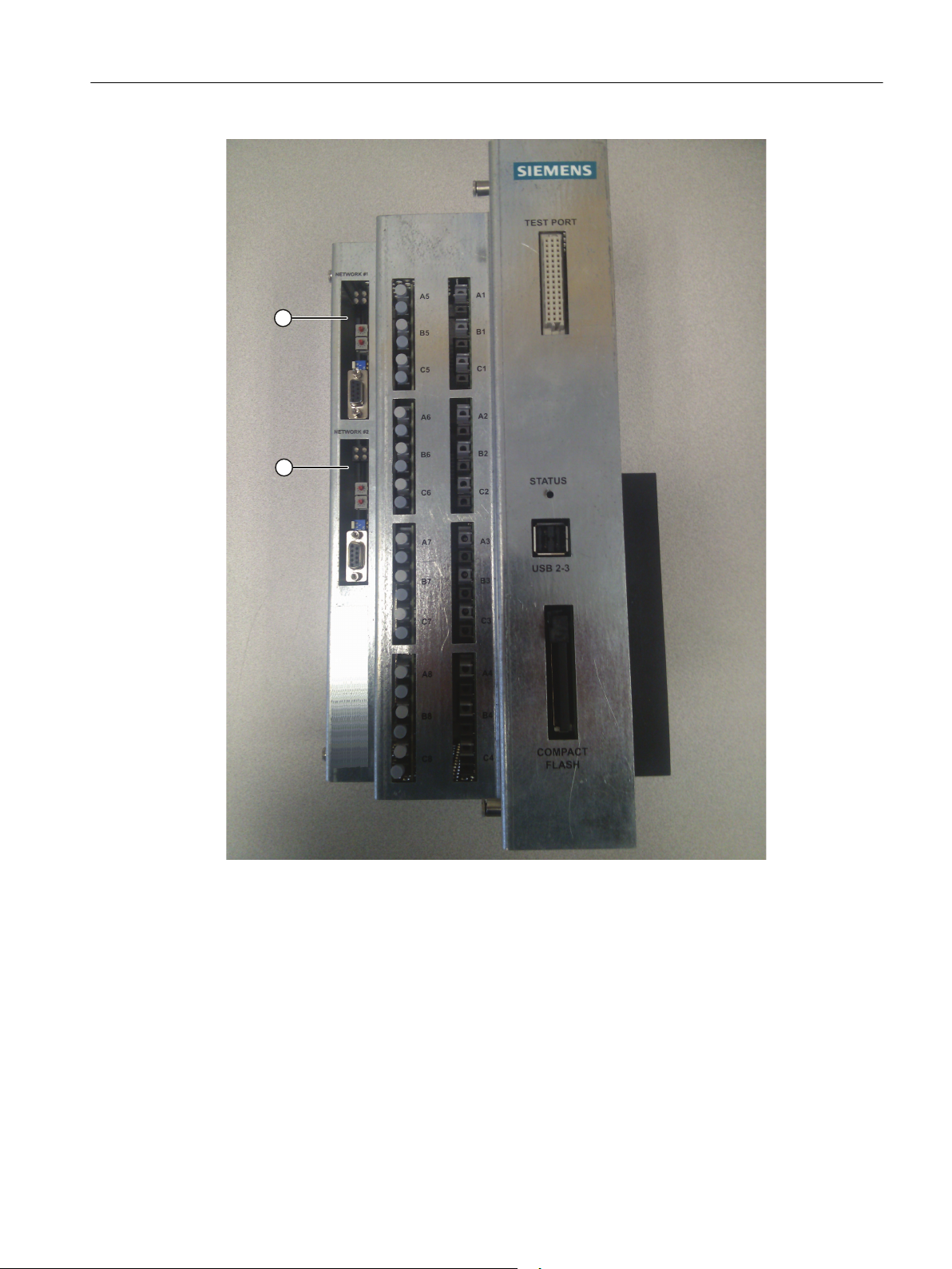
The following figure shows the NXGpro Control and includes the locations of the connectors
for the Anybus™ modules (network 1 and 2).
NXGpro Communication
18 Function Manual, AB, A5E33486415A
Page 19
Introduction
1.1 Communication Overview
1 Network 1
2 Network 2
Figure 1-1 NXGpro Control
See also
Ethernet / IP Communication (Page 107)
NXGpro Communication
Function Manual, AB, A5E33486415A 19
Page 20

Introduction
1.2 Remote Capabilities
1.2 Remote Capabilities
The communication interface to the drive allows remote control and monitoring of the drive.
Control of the drive can be achieved through registers or telegrams that are sent to the drive,
working in conjunction with the system program (SOP).
This allows for a range of control capabilities including:
● run request
● stop request
● fault reset
● stop
● reverse speed demand.
There are 128 remote user-programmable software flags that can be monitored and/or set
through the SOP:
● 64 programmable inputs
● 64 programmable outputs
Where applicable, refer to the
information.
Note
Discrete controls and user-defined control/feedback flags are configured through the drive's
built-in SOP that is provided with each drive.
Software Programming
Section of a chapter for further
NXGpro Communication
20 Function Manual, AB, A5E33486415A
Page 21

1.3 RS232 Port
Introduction
1.3 RS232 Port
Use the RS232 port shown in Figure
external modem. Refer to Appendix
NXGpro Control
External Modem
to remotely monitor the drive via an
for further information.
NXGpro Communication
Function Manual, AB, A5E33486415A 21
Page 22

Introduction
1.4 Optional Hardware requirement for Dual Networks
1.4 Optional Hardware requirement for Dual Networks
The NXGpro Control supports dual networks, utilizing network 1 and network 2. To enable
dual network functionality, a protocol may require additional hardware, for example, an
additional Anybus™ module.
Refer to the
hardware requirements and setup options are detailed.
Description
Section of the chapter for a particular protocol where additional
NXGpro Communication
22 Function Manual, AB, A5E33486415A
Page 23

1.5 Entering Parameter IDs
Throughout this manual, a four digit number inside of parentheses, for example (9403),
indicates a parameter ID number that can be entered using one of the following methods:
● the keypad located on the front of the drive
Introduction
1.5 Entering Parameter IDs
● the ToolSuite, a PC-based application software package (refer to the
Manual
Use the following procedure to enter a parameter ID:
1. Press [SHIFT] + [→]. You do not need to hold down the [SHIFT] key while you press the [→]
key.
2. Enter the ID number.
Note
Refer to the
operation and entering parameter ID numbers.
for more information).
NXGpro Control Operating Manual
for complete information on keypad
NXGpro ToolSuite
NXGpro Communication
Function Manual, AB, A5E33486415A 23
Page 24

Introduction
1.5 Entering Parameter IDs
NXGpro Communication
24 Function Manual, AB, A5E33486415A
Page 25

Safety notes
2.1 General Safety Information
Proper Use
SINAMICS PERFECT HARMONY GH180 medium voltage drives must always be installed in
closed electrical operating areas. The drive is connected to the industrial network via a circuitbreaker.
The specific transport conditions must be observed when the equipment is transported. The
equipment shall be assembled/installed and the separate cabinet units connected properly by
cable and/or busbar in accordance with the assembly/installation instructions. The relevant
instructions regarding correct storage, EMC-compliant installation, cabling, shielding and
grounding and an adequate auxiliary power supply must be strictly observed. Fault-free
operation is also dependent on careful operation and maintenance. Refer to the drive's
Operating Instructions Manual, Section
The power sections are designed for variable-speed drives use with synchronous and
asynchronous motors. Operating modes, overload conditions, load cycles, and ambient
conditions different to those described in this document are allowed only by special
arrangement with the manufacturer.
EMC Installation Guidelines
2
.
Commissioning should only be carried out by trained service personnel in accordance with the
commissioning instructions.
System components such as circuit-breaker, transformer, cables, cooling unit, motor, speed
sensors, etc., must be matched to VFD operation. System configuration may only be carried
out by an experienced system integrator.
NXGpro Communication
Function Manual, AB, A5E33486415A 25
Page 26

Safety notes
2.2 Safety Concept
2.2 Safety Concept
The medium-voltage variable frequency drive (VFD) and its components are subject to a
comprehensive safety concept which, when properly implemented, ensures safe installation,
operation, servicing, and maintenance.
The safety concept encompasses safety components and functions to protect the device and
operators.
The VFD is also equipped with monitoring functions to protect external components.
The VFD operates safely when the interlock and protection systems are functioning properly.
Nevertheless, there are areas on the medium-voltage drive that are hazardous for personnel
and that can cause material damage if the safety instructions described in this section and
throughout the product documentation are not strictly observed.
NXGpro Communication
26 Function Manual, AB, A5E33486415A
Page 27

2.3 Observing the Five Safety Rules
There are five safety rules that must always be observed to assure not only personal safety,
but to prevent material damage as well. Always obey safety-related labels located on the
product itself and always read and understand each safety precaution prior to operating or
working on the drive.
The five safety rules:
1. Disconnect the system.
2. Protect against reconnection.
3. Make sure that the equipment is de-energized.
4. Apply grounding means.
5. Cover or enclose adjacent components that are still live.
DANGER
Danger Due to High Voltages
High voltages cause death or serious injury if the safety instructions are not observed or if
the equipment is handled incorrectly.
Safety notes
2.3 Observing the Five Safety Rules
Potentially fatal voltages occur when this equipment is in operation which can remain present
even after the VFD is switched off.
Ensure that only qualified and trained personnel carry out work on the equipment.
Follow the five safety rules during each stage of the work.
NXGpro Communication
Function Manual, AB, A5E33486415A 27
Page 28

Safety notes
2.4 Safety Information and Warnings
2.4 Safety Information and Warnings
DANGER
Hazardous Voltage!
● Always follow the proper lock-out/tag-out procedures before beginning any maintenance
or troubleshooting work on the VFD.
● Always follow standard safety precautions and local codes during installation of external
wiring. The installation must follow wiring practices and insulation systems as specified in
IEC 61800-5-1.
● Always work with one hand, wear electrical safety gloves, wear insulated electrical hazard
rated safety shoes, and safety goggles. Also, always work with another person present.
● Always use extreme caution when handling or measuring components that are inside the
enclosure. Be careful to prevent meter leads from shorting together or from touching other
terminals.
● Use only instrumentation (e.g., meters, oscilloscopes, etc.) intended for high voltage
measurements (that is, isolation is provided inside the instrument, not provided by isolating
the chassis ground of the instrument).
● Never assume that switching off the input disconnector will remove all voltage from internal
components. Voltage is still present on the terminals of the input disconnector. Also, there
may be voltages present that are applied from other external sources.
● Never touch anything within the VFD cabinets until verifying that it is neither thermally hot
nor electrically alive.
● Never remove safety shields (marked with a HIGH VOLTAGE sign) or attempt to measure
points beneath the shields.
● Never operate the VFD with cabinet doors open. The only exception is the control cabinet
which contains extra low voltages (ELV).
● Never connect any grounded (i.e., non-isolated) meters or oscilloscopes to the system.
● Never connect or disconnect any meters, wiring, or printed circuit boards while the VFD
is energized.
● Never defeat the instrument’s grounding.
● Only qualified individuals should install, operate, troubleshoot, and maintain this VFD. A
qualified individual is "a person, who is familiar with the construction and operation of the
equipment and the hazards involved."
● Hazardous voltages may still exist within the VFD cabinets even when the disconnect
switch is open (off) and the supply power is shut off.
● When a system is configured with VFD bypass switchgear (e.g. contactors between line
and motor, and VFD and motor), these switches should be interlocked so that the line
voltage is never applied to the VFD output if the medium input voltage is removed from
the VFD.
NXGpro Communication
28 Function Manual, AB, A5E33486415A
Page 29
Safety notes
2.4 Safety Information and Warnings
WARNING
Potential Arc Hazard
● Arcing can result in damage to property, serious injury and even death.
● The equipment has not been tested and rated for arc flash protection.
● Avoiding arc hazard risks is dependent upon proper installation and maintenance.
● Incorrectly applied equipment, incorrectly selected, connected or unconnected cables, or
the presence of foreign materials can cause arcing in the equipment.
● Follow all applicable precautionary rules and guidelines as used in working with medium
voltage equipment.
● The equipment may be used only:
– for the applications defined as suitable in the technical description.
– in combination with equipment and components supplied by other manufacturers which
have been approved and recommended by Siemens.
Additional safety precautions and warnings appear throughout this manual. These important
messages should be followed to reduce the risk of personal injury or equipment damage.
WARNING
Obey Rules to Avoid Risk of Death
● Always comply with local codes and requirements if disposal of failed components is
necessary (for example, CPU battery, capacitors, etc.).
● Always ensure the use of an even and flat truck bed to transport the VFD system. Before
unloading, be sure that the concrete pad is level for storage and permanent positioning.
● Always confirm proper tonnage ratings of cranes, cables, and hooks when lifting the VFD
system. Dropping the cabinet or lowering it too quickly could damage the unit.
● Never disconnect control power while medium voltage is energized. This could cause
severe system overheating and/or damage.
● Never store flammable material in, on, or near the drive enclosure. This includes
equipment drawings and manuals.
● Never use fork trucks to lift cabinets that are not equipped with lifting tubes. Be sure that
the fork truck tines fit the lifting tubes properly and are the appropriate length.
NXGpro Communication
Function Manual, AB, A5E33486415A 29
Page 30

Safety notes
2.5 ESD-sensitive Components
2.5 ESD-sensitive Components
Guidelines for Handling Electrostatic Sensitive Devices (ESD)
NOTICE
ESD Sensitive Equipment
● Always be aware of electrostatic discharge (ESD) when working near or touching
components inside the VFD cabinet. The printed circuit boards contain components that
are sensitive to electrostatic discharge. Handling and servicing of components that are
sensitive to ESD should be done only by qualified personnel and only after reading and
understanding proper ESD techniques. The following ESD guidelines should be observed.
Following these rules can greatly reduce the possibility of ESD damage to printed circuit
board (PCB) components.
● Always transport static sensitive equipment in antistatic bags.
● Always use a soldering iron that has a grounded tip. Also, use either a metallic vacuumstyle plunger or copper braid when desoldering.
● Ensure that anyone handling the printed circuit boards is wearing a properly grounded
static strap. The wrist strap should be connected to ground through a 1 Megohm resistor.
Grounding kits are available commercially through most electronic wholesalers.
● Static charge build-up can be removed from a conductive object by touching the object
with a properly grounded piece of metal.
● When handling a PC board, always hold the card by its edges.
● Do not slide printed circuit boards (PCBs) across any surface (e.g., a table or work bench).
If possible, perform PCB maintenance at a workstation that has a conductive covering that
is grounded through a 1 Megohm resistor. If a conductive tabletop cover is unavailable, a
clean steel or aluminum tabletop is an excellent substitute.
● Avoid plastic Styrofoam™, vinyl and other non-conductive materials. They are excellent
static generators and do not give up their charge easily.
● When returning components to Siemens Industry, Inc. always use static-safe packing.
This limits any further component damage due to ESD.
Components that can be destroyed by electrostatic discharge (ESD)
NOTICE
Electrostatic discharge
Electronic components can be destroyed in the event of improper handling, transporting,
storage, and shipping.
Pack the electronic components in appropriate ESD packaging; e.g. ESD foam, ESD
packaging bags and ESD transport containers.
To protect your equipment against damage, follow the instructions given below.
NXGpro Communication
30 Function Manual, AB, A5E33486415A
Page 31
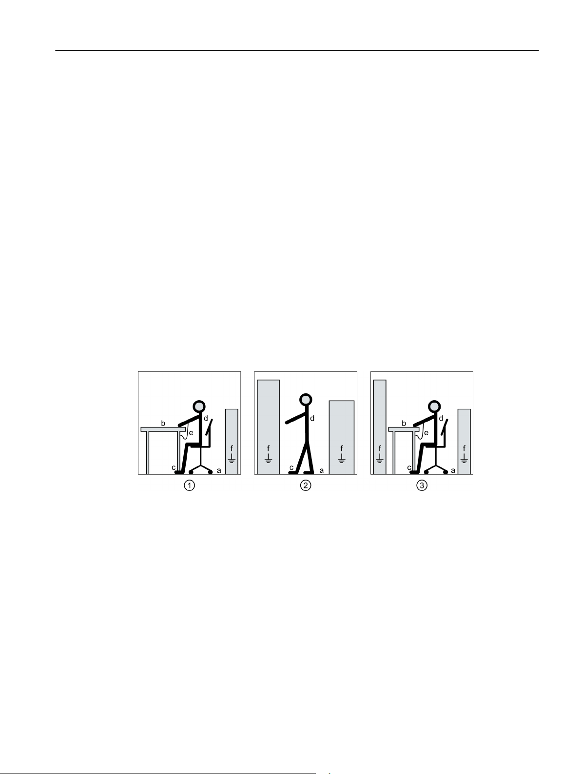
Safety notes
2.5 ESD-sensitive Components
● Avoid physical contact with electronic components. If you need to perform absolutely
essential work on these components, then you must wear one of the following protective
gear:
– Grounded ESD wrist strap
– ESD shoes or ESD shoe grounding strips if there is also an ESD floor.
● Do not place electronic components close to data terminals, monitors or televisions.
Maintain a minimum clearance to the screen (> 10 cm).
● Electronic components should not be brought into contact with electrically insulating
materials such as plastic foil, plastic parts, insulating table supports or clothing made of
synthetic fibers.
● Place components in contact with ESD-suited materials e.g. ESD tables, ESD surfaces,
ESD packaging.
● Measure on the components only if one of the following conditions is met:
– The measuring device is grounded with a protective conductor, for example.
– The measuring head of a floating measuring device has been discharged directly before
the measurement.
The necessary ESD protective measures for the entire working range for electrostatically
sensitive devices are illustrated once again in the following drawings. Precise instructions for
ESD protective measures are specified in the standard DIN EN 61340-5-1.
1 Sitting
2 Standing
3 Standing/sitting
a Conductive floor surface, only effective in conjunction with ESD shoes or ESD shoe grounding
strips
b ESD furniture
c ESD shoes or ESD shoe grounding strips are only effective in conjunction with conductive floor‐
ing
d ESD clothing
e ESD wristband
f Cabinet ground connection
Figure 2-1 ESD Protective Measures
NXGpro Communication
Function Manual, AB, A5E33486415A 31
Page 32
Safety notes
2.6 Electromagnetic Fields in Electrical Power Engineering Installations
2.6 Electromagnetic Fields in Electrical Power Engineering Installations
WARNING
Electromagnetic fields "electro smog" when operating electrical power engineering
installations
Electromagnetic fields are generated during operation of electrical power engineering
installations.
Electromagnetic fields can interfere with electronic devices, which could cause them to
malfunction. For example, the operation of heart pacemakers can be impaired, potentially
leading to damage to a person's health or even death. It is therefore forbidden for persons
with heart pacemakers to enter these areas.
The plant operator is responsible for taking appropriate measures (labels and hazard
warnings) to adequately protect operating personnel and others against any possible risk.
● Observe the relevant nationally applicable health and safety regulations. For example, in
Germany, "electromagnetic fields" are subject to regulations BGV B11 and BGR B11
stipulated by the German statutory industrial accident insurance institution.
● Display adequate hazard warning notices on the installation.
● Place barriers around hazardous areas.
● Take measures, e.g. using shields, to reduce electromagnetic fields at their source.
● Ensure personnel are wearing the appropriate protective gear.
NXGpro Communication
32 Function Manual, AB, A5E33486415A
Page 33

2.7 Security Information
Siemens provides products and solutions with industrial security functions that support the
secure operation of plants, solutions, machines, equipment and/or networks. They are
important components in a holistic industrial security concept. With this in mind, Siemens’
products and solutions undergo continuous development. Siemens recommends strongly that
you regularly check for product updates.
For the secure operation of Siemens products and solutions, it is necessary to take suitable
preventive action and integrate each component into a holistic, state-of-the-art industrial
security concept. Third-party products that may be in use should also be considered. For more
information about industrial security, visit http://www.siemens.com/industrialsecurity.
To stay informed about product updates as they occur, sign up for a product-specific
newsletter. For more information, visit http://support.automation.siemens.com.
Safety notes
2.7 Security Information
NXGpro Communication
Function Manual, AB, A5E33486415A 33
Page 34

Safety notes
2.7 Security Information
NXGpro Communication
34 Function Manual, AB, A5E33486415A
Page 35

Modbus Communication
This chapter contains instructions for controlling the drive using a PLC over a Modbus™
network. It addresses the following topics:
● Description of the interface
● User Programming
● Parameter assignment and addressing
● Configuration and setup options
● Available functions
3
NXGpro Communication
Function Manual, AB, A5E33486415A 35
Page 36

Modbus Communication
3.1 Description
3.1 Description
The Modbus™ communication interface is a serial interface that operates at standard baud
rates up to 19.2 Kbaud. The 10-bit data frame consists of 1 start bit, 8 data bits (no parity) and
1 stop bit. These data parameters are fixed for the drive.
The drive always acts as a Modbus™ slave. This means that the drive does not initiate dialog
on the Modbus™ network. Rather, it listens to and then responds to the Modbus™ master (the
PLC).
Note
Only register-based read and write functions of the Modbus™ protocol are supported. These
functions are used to monitor and control analog and digital inputs and outputs of the drive.
Only the Remote Terminal Unit (RTU) format of the Modbus™ protocol is supported by the
NXGpro Control.
Refer to Section
Functions
for function codes supported by the NXGpro Control.
See also
Functions (Page 64)
3.1.1 Network Configuration Options
This section provides information on the configuration options for the Siemens Modbus™
module for single or dual network functionality.
NXGpro Communication
36 Function Manual, AB, A5E33486415A
Page 37
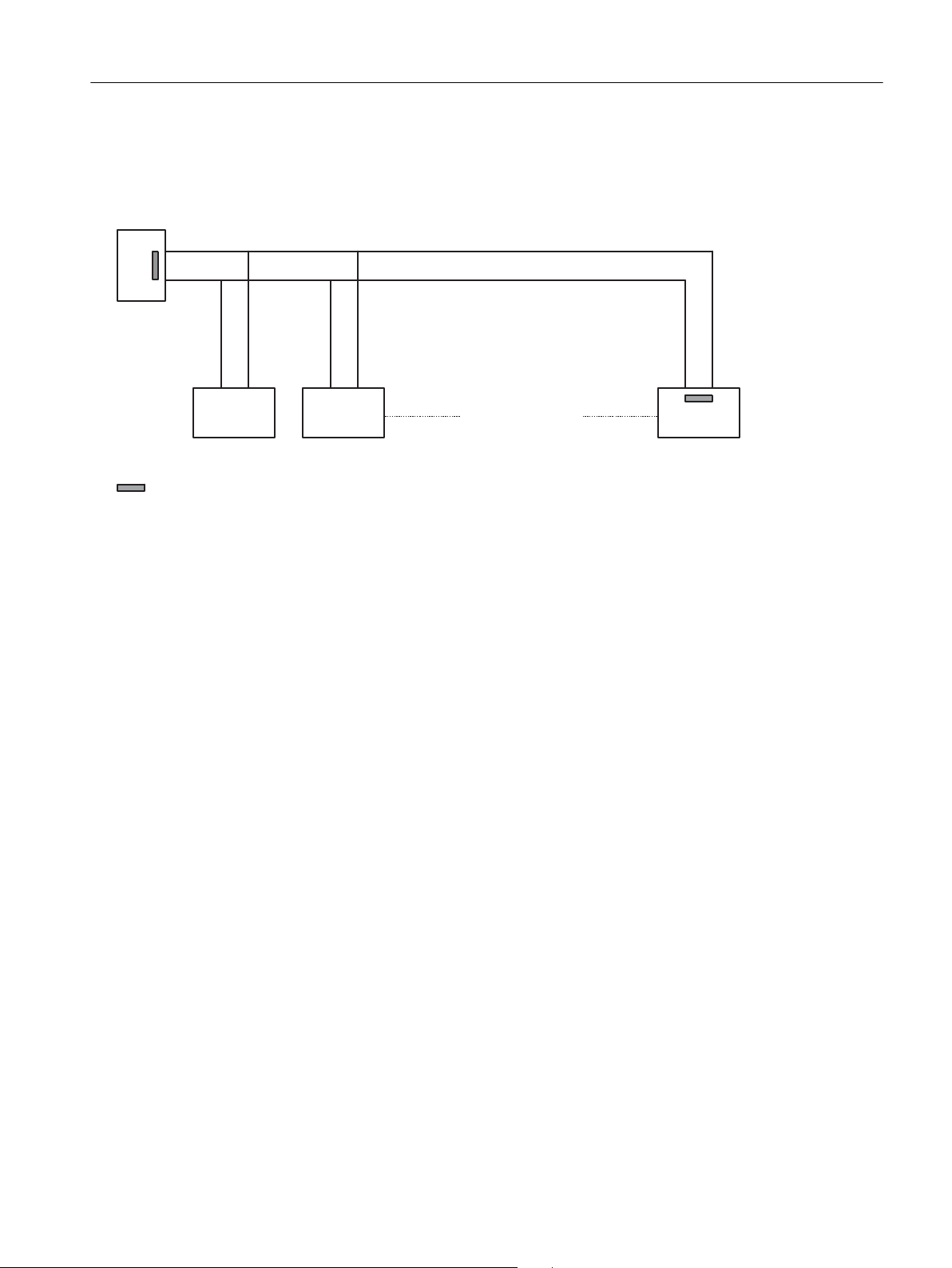
Modbus Communication Network Connections
1RWH$%GHILQLWLRQVDUHQRWVWDQGDUG,IWKHXQLWGRHVQRWZRUN
\RXPD\QHHGWRVZDS$DQG%
0D[FRQQHFWLRQV
1;*&RQWUROV0RGEXVVODYHV
7HUPLQDWLRQ
1RWH7KHJURXQGLVORFDWHGRQ3LQRIHDFKGULYH
1RWH8VHWZLVWHGSDLUZLULQJLIVKLHOGHGFRQQHFWRQO\DWRQHHQG
0RGEXV0DVWHU
=
A
B
B A B A AB
Modbus™ network communication is shown below.
Modbus Communication
3.1 Description
Figure 3-1 Typical 2-wire Modbus Communication Connection
3.1.2 Siemens Modbus Module
Description
The Siemens Modbus™ module supports Modbus™ communication. The module plugs into
the Anybus 1 (ABUS1) connector or the Anybus 2 (ABUS2) connector on the fiber optic board,
as shown in Figure
The following figure shows the connector and status indicators on the Siemens Modbus™
module.
NXGpro Control
in the
Introduction
Chapter.
NXGpro Communication
Function Manual, AB, A5E33486415A 37
Page 38
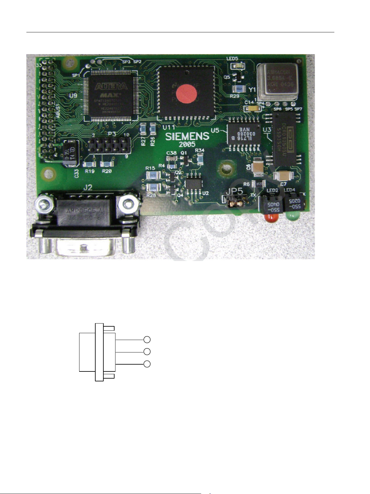
Modbus Communication
3.1 Description
Figure 3-2 Siemens Modbus Module
Connector
The module has fixed pin assignments for Data A and Data B. The following figure shows the
output pin configuration for RS485.
1 Pin 2: Data A
2 Pin 3: Data B
3 Pin 5: Ground
Figure 3-3 RS485 Pin Assignments
38 Function Manual, AB, A5E33486415A
NXGpro Communication
Page 39
Status Indicators
Modbus Communication
3.1 Description
The following table explains the status indicators as shown in Figure
Module
Table 3-1 Status Indicator Descriptions
Status Indicator LED Indication
Red Module is sending data to the Modbus network
Green Module is receiving data from the Modbus network
Note
The green LED does not indicate that network traffic is present for this specific device; it only
means that network traffic is present.
Termination Resistor
The module incorporates a jumper (JP5), which can be used to terminate the network line as
listed in the following table.
Table 3-2 Jumper to enable/disable Termination Resistor
Jumper Setting
JP5 = 1-2 Termination resistor disabled
JP5 = 2-3 Termination resistor enabled
Siemens Modbus
.
NXGpro Communication
Function Manual, AB, A5E33486415A 39
Page 40

Modbus Communication
3.2 Software Programming
3.2 Software Programming
This section provides details for user programming through the SOP.
The fixed register bits are defined by the drive's software by default. To reprogram the definition
of the bits, complete these steps:
1. Set parameters using the procedure
controlled by the SOP
2. Refer to the procedures detailed in this section to complete setup:
– programmable inputs to the drive
– programmable outputs from the drive
The following table shows how the fixed register bits correspond with programmable bits
available for use in the SOP (drctry.pro bits).
Table 3-3 Network 1 and 2: Fixed Register Bits
Pick list variable in 'Data to Drive Reg nn' menus Corresponding Drctry.pro bits Modbus Address
Fixed Reg Bits (network 1) Network1FixedRegBit0_I ~ Network1FixedReg‐
Fixed Reg Bits (network 2) Network2FixedRegBit0_I ~ Network2FixedReg‐
in Section
Bit15_I
Bit15_I
Fast Setup: control the drive using user-defined bits
Planning/Configuring.
40065
40065
3.2.1 Programmable Inputs to the Drive
Description
There are 64 input bits available for user programming through the SOP file. These bits can
be programmed to set or reset any other bits used within the SOP.
Programming Procedure
1. Locate the first data to drive register that is programmable using Table
between Drive Parameter ID and Communication Protocol Address
Assignment/Addressing
You will see that the first programmable data to drive register for network 1 is register 'Data
to Drive 03', which corresponds to parameter ID (9603).
2. Enter parameter ID (9603).
3. The pick list of data to drive variables will appear. Refer to Table
Variables and Scaling
drive pick list variables.
40 Function Manual, AB, A5E33486415A
.
in Section
Parameter Assignment/Addressing
Correspondence
in Section
Parameter
Data to Drive Pick List
for a list of data to
NXGpro Communication
Page 41

Modbus Communication
3.2 Software Programming
4. Scroll through the pick list until you come to 'Net Input Flag 1' and press [ENTER]. This
setting uses the first 16 bits of the possible 64 bits.
Now the corresponding bits from the drctry.pro file can be used in the SOP, as shown below:
;Network1Flag0_I Use bit 0 for Stop bit
;Network1Flag1_I Use bit 1 for Run Forward bit
RunRequest_O = /Network1Flag0_I * Network1Flag1_I;Run drive using
bit 1,stop using bit 0
5. Select 'Net Input Flag 2' to use the second set of 16 bits, and so on.
Note
By choosing 'Data to Drive 03' as the write register, the PLC must now send 0x02 in register
'Data to Drive 03' to run the drive.
To stop the drive, the PLC must send 0x01 in register 'Data to Drive 03'.
The pick list variables and the corresponding programmable input bits are found in the following
tables for network 1 and 2, respectively.
Table 3-4 Network 1: Programmable input bits (parameter ID 9603-9664)
Example
Pick list variable in 'Data to Drive Reg nn' menus Related Drctry.pro bits
Net Input Flag 1 Network1Flag0_I ~ Network1Flag15_I
Net Input Flag 2 Network1Flag16_I ~ Network1Flag31_I
Net Input Flag 3 Network1Flag32_I ~ Network1Flag47_I
Net Input Flag 4 Network1Flag48_I ~ Network1Flag63_I
Table 3-5 Network 2: Programmable input bits (parameter ID 9703-9764)
Pick list variable in 'Data to Drive Reg nn' menus Related Drctry.pro bits
Net Input Flag 1 Network2Flag0_I ~ Network2Flag15_I
Net Input Flag 2 Network2Flag16_I ~ Network2Flag31_I
Net Input Flag 3 Network2Flag32_I ~ Network2Flag47_I
Net Input Flag 4 Network2Flag48_I ~ Network2Flag63_I
The following example shows how the network can be programmed to trip the input medium
voltage:
● The PLC writes to register 'Data to Drive 03' which is programmed to 'Net Input Flag 1'
using the procedure above.
● The SOP sets a flag bit that uses a digital output to trip input medium voltage, using the
following SOP source code:
;ExternalDigitalOutput01h_O Use digital output to trip input medium voltage
ExternalDigitalOutput01h_O = Network1FixedRegBit9_I;
NXGpro Communication
Function Manual, AB, A5E33486415A 41
Page 42

Modbus Communication
3.2 Software Programming
● The PLC writes the contents of 'Net Input Flag 1', bit 9 (Network1Flag9_I) to create an input
medium voltage trip.
3.2.2 Programmable Outputs from the Drive
Description
There are 64 output bits available for user programming through the SOP file. These bits can
be programmed to set or reset any other bits used within the SOP.
Programming Procedure
1. Locate the first data from drive register that is programmable using Table
between Drive Parameter ID and Communication Protocol Address
Assignment/Addressing
.
Correspondence
in Section
Parameter
You will see that the first programmable data from drive register for network 1 is register
'Data from Drive 03', which corresponds to parameter ID (9403).
2. Enter parameter ID (9403).
3. The pick list of data from drive variables will appear. Refer to Table
List Variables
in Section
Parameter Assignment/Addressing
for a list of data from drive pick
Data from Drive Pick
list variables.
4. Scroll through the pick list until you come to 'Net1 Out Reg 1' and press [ENTER]. This
setting uses the first 16 bits of the possible 64 bits.
5. Select 'Net1 Out Reg 2' to use the second set of 16 bits, and so on.
The pick list variables and the corresponding programmable output bits are found in the
following tables for network 1 and 2, respectively.
Table 3-6 Network 1: Programmable output bits (parameter ID 9403-9464)
Pick list variable in 'Data from Drive Reg nn' menus Related Drctry.pro bits
Net1 Out Reg 1 Network1Flag0_O ~ Network1Flag15_O
Net1 Out Reg 2 Network1Flag16_O ~ Network1Flag31_O
Net1 Out Reg 3 Network1Flag32_O ~ Network1Flag47_O
Net1 Out Reg 4 Network1Flag48_O ~ Network1Flag63_O
Table 3-7 Network 2: Programmable output bits (parameter ID 9503-9564)
Pick list variable in 'Data from Drive Reg nn' menus Related Drctry.pro bits
Net2 Out Reg 1 Network2Flag0_O ~ Network2Flag15_O
Net2 Out Reg 2 Network2Flag16_O ~ Network2Flag31_O
Net2 Out Reg 3 Network2Flag32_O ~ Network2Flag47_O
Net2 Out Reg 4 Network2Flag48_O ~ Network2Flag63_O
NXGpro Communication
42 Function Manual, AB, A5E33486415A
Page 43

Example
Modbus Communication
3.2 Software Programming
The following example shows how the network can be programmed to detect a trip on the input
medium voltage:
● The PLC reads register 'Data from Drive 03', which is programmed to 'Net1 Out Reg 1'
using the procedure above.
● The SOP sets a flag bit that corresponds to a medium voltage low fault, using the following
SOP source code:
; Monitor medium voltage fault on the Modbus network
Network1Flag9_O = MediumVoltageLowFault_I;
● This example uses bit 9 of 'Net1 Out Reg 1', which is Network1Flag9_O, to set the network
flag true if the medium voltage low fault is active.
● The PLC reads the contents of 'Net1 Out Reg 1', bit 9 (Network1Flag9_O) to determine if
a medium voltage fault occured.
NXGpro Communication
Function Manual, AB, A5E33486415A 43
Page 44

Modbus Communication
3.3 Parameter Assignment/Addressing
3.3 Parameter Assignment/Addressing
This section provides the following information for communication configuration and
programming:
● Drive parameter ID and corresponding communication protocol address
● Parameter tables:
– Network configuration parameters
– Network 1 configuration parameters
– Network 2 configuration parameters
● Pick list variable tables:
– Data from Drive variables
– Data to Drive variables
3.3.1 Correspondence between Drive Parameter ID and Communication Protocol Address
The following table provides drive parameter IDs and the corresponding Modbus™ addresses.
The following data is provided:
● Parameter ID
The drive parameter ID number to enter via the keypad or the ToolSuite.
● Modbus™ Address
A digital location provided by the Modbus™ Protocol, which stores values for use by the
master (PLC) and slave (Siemens drive) devices. To establish functional communication
between the PLC and the drive via the drive's Modbus™ connection, the control software
in the drive must be configured to know what certain addresses are used for.
● Data From Drive
Data that the PLC will receive from the drive to determine how the drive is functioning.
Each register contains a 16-bit digital representation of the status of a particular aspect of
drive functionality.
Some registers are fixed to track certain drive functions; others are programmable to track
any of a number of drive status choices.
● Data To Drive
Data that the PLC will send to the drive to control it.
Each register contains a 16-bit digital representation of the PLC's command for a particular
aspect of drive functionality.
Some registers are fixed to control certain functions; others are programmable to control
any of a number of drive function choices.
Table 3-8 Correspondence between Drive Parameter ID and Modbus Address
Network Parameter ID Description Default Contents Modbus Address
1 9401 Data From Drive 01 General Status (not changea‐
ble)
1 9402 Data From Drive 02 Motor Speed (not changeable) 40002
44 Function Manual, AB, A5E33486415A
40001
NXGpro Communication
Page 45
Modbus Communication
3.3 Parameter Assignment/Addressing
Network Parameter ID Description Default Contents Modbus Address
1 9403 to 9464 Data From Drive 03 to 64 None 40003 to 40064
1 9601 Data To Drive 01 Fixed Register Bits (not
changeable)
1 9602 Data To Drive 02 Velocity Demand (not change‐
able)
1 9603 to 9664 Data To Drive 03 to 64 None 40067 to 40128
2 9501 Data From Drive 01 General Status (not changea‐
ble)
2 9502 Data From Drive 02 Motor Speed (not changeable) 40002
2 9503 to 9564 Data From Drive 03 to 64 None 40003 to 40064
2 9701 Data To Drive 01 Fixed Register Bits (not
changeable)
2 9702 Data To Drive 02 Velocity Demand (not change‐
able)
2 9703 to 9764 Data To Drive 03 to 64 None 40067 to 40128
40065
40066
40001
40065
40066
3.3.2 Parameter Tables
Network Parameters
Table 3-9 Network Control Menu (9943)
Parameter ID Unit Default Min Max Description
Net Control Type 9944 Sop Set bit definition:
● SOP
● Fixed
Start Stop Control 9945 Maintained Set Start/Stop bit inputs:
● Maintained
● Momentary
Table 3-10 Network 1 to 2 Register Copy (9946)
Parameter ID Unit Default Min Max Description
Net 1 to 2 reg. copy 9946 Function Copy Network 1 registers to Network 2
registers.
NXGpro Communication
Function Manual, AB, A5E33486415A 45
Page 46

Modbus Communication
3.3 Parameter Assignment/Addressing
Network 1 Parameters
Table 3-11 Network 1: Configure Menu (9900)
Parameter ID Unit Default Min Max Description
Network 1 Type 9901 None Designate the type of external network connected to
the drive:
● None
● Modbus
● DeviceNet
● Profibus
● Ethernet Modbus
● ControlNet
● Ethernet I/P
Table 3-12 Network 1: Configure Parameters Menu (9902)
Parameter ID Unit Default Min Max Description
Modbus Baud Rate 9060 19200 Set the Modbus network baud rate:
● 1200
● 2400
● 4800
● 9600
● 19200
Modbus Parity 9047 None Set the Modbus parity:
● none
● odd
● even
Modbus Stop Bits 9048 1 Set the Modbus stop bits:
● one
● two
Modbus Address 9070 1 1 247 Set the address of the node on the Modbus network.
Velocity Units 9080 % Designate the units for velocity values from the drive:
● %
● RPM
● Hz
Demand Scalar 9912 1 -125 125 Set the scalar for input demand reference from the
network.
Aux Demand Scalar 9913 1 -125 125 Set the auxiliary scalar for input demand reference
from the network.
Network Timeout 9934 0 0 65535 Set the timeout for network determined to be non-re‐
sponsive.
NXGpro Communication
46 Function Manual, AB, A5E33486415A
Page 47

Modbus Communication
3.3 Parameter Assignment/Addressing
Table 3-13 Network 1: Register Data from Drive Menu (9400)
Parameter ID Unit Default Min Max Description
Data From Drive 01 9401 General Sta‐
tus
Data From Drive 02 9402 Motor Speed Register data from drive parameter 2.
Data From Drive 03 to 64 9403 to
9464
Table 3-14 Network 1: Register Data to Drive Menu (9600)
Parameter ID Unit Default Min Max Description
Data To Drive Reg 01 9601 Fixed Reg
Data To Drive Reg 02 9602 Velocity De‐
Data To Drive Reg 03 to 64 9603 to
9664
None Register data from drive parameters 3 to 64.
Bits
mand
None Register data to drive parameters 3 to 64.
Register data from drive parameter 1.
Register is not programmable.
Register is not programmable.
Registers are programmable.
Register data to drive parameter 1.
Register is not programmable.
Register data to drive parameter 2.
Register is not programmable.
Registers are programmable.
Network 2 Parameters
Table 3-15 Network 2: Configure Menu (9914)
Parameter ID Unit Default Min Max Description
Network 2 Type 9915 None Designate the type of external network connected to the
drive:
● None
● Modbus
● DeviceNet
● Profibus
● Ethernet Modbus
● ControlNet
● Ethernet I/P
NXGpro Communication
Function Manual, AB, A5E33486415A 47
Page 48
Modbus Communication
3.3 Parameter Assignment/Addressing
Table 3-16 Network 2: Configure Parameters Menu (9916)
Parameter ID Unit Default Min Max Description
Modbus Baud Rate 9917 19200 Set the Modbus network baud rate:
● 1200
● 2400
● 4800
● 9600
● 19200
Modbus Parity 9947 None Set the Modbus parity:
● none
● odd
● even
Modbus Stop Bits 9948 1 Set the Modbus stop bits:
● one
● two
Modbus Address 9920 1 1 247 Set the address of the node on the Modbus network.
Velocity Units 9924 % Designate the units for velocity values from the drive:
● %
● RPM
● Hz
Demand Scalar 9926 1 -125 125 Set the scalar for input demand reference from the
network.
Aux Demand Scalar 9927 1 -125 125 Set the auxiliary scalar for input demand reference
from the network.
Network Timeout 9935 0 0 65535 Set the timeout for network determined to be non-re‐
sponsive.
Table 3-17 Network 2: Register Data from Drive Menu (9500)
Parameter ID Unit Default Min Max Description
Data From Drive 01 9501 General Sta‐
tus
Data From Drive 02 9502 Motor Speed Register data from drive parameter 2.
Data From Drive 03 to 64 9503 to
9564
None Register data from drive parameters 3 to 64.
Register data from drive parameter 1.
Register is not programmable.
Register is not programmable.
Registers are programmable.
NXGpro Communication
48 Function Manual, AB, A5E33486415A
Page 49

3.3 Parameter Assignment/Addressing
Table 3-18 Network 2: Register Data to Drive Menu (9700)
Parameter ID Unit Default Min Max Description
Data To Drive Reg 01 9701 Fixed Reg
Bits
Data To Drive Reg 02 9702 Velocity De‐
mand
Data To Drive Reg 03 to 64 9703 to
9764
None Register data to drive parameters 3 to 64.
Register data to drive parameter 1.
Register is not programmable.
Register data to drive parameter 2.
Register is not programmable.
Registers are programmable.
Modbus Communication
NXGpro Communication
Function Manual, AB, A5E33486415A 49
Page 50

Modbus Communication
3.3 Parameter Assignment/Addressing
3.3.3 Pick List Variable Tables
Table 3-19 Data from Drive Pick List Variables
Name
None None None None None None
Man Id None None None None Refer to Appendix
General Status 2001 None None Bit Field
Motor Voltage 2100 Volts /1 Unsigned
Total Current 2190 Amps /1 Unsigned
Output Power 2230 KW /1 Signed
Motor Speed 2014 % /10 Unsigned
Speed Demand 2060 % /100 Unsigned
Speed Reference 2010 % /100 Unsigned
Heartbeat 2220 None None Unsigned 1 count per millisecond
Drive State 2210 None None Unsigned
Inp RMS Current 2130 Amps /1 Unsigned
Manual ID Unit Scaling 16 Bit Data
Type
RPM /1
Hz /10
Notes
Internal Drive Network
● Bit 0: Fault
● Bit 1: Alarm
● Bit 2: Running Forward
● Bit 3: Running Reverse
● Bit 4: Drive Ready
● Bit 5: Start/Stop Control From Network
● Bit 6: Speed Reference From Network
● Bit 7: At Speed Reference
● Bit 8: Speed In Percent
● Bit 9: Speed In RPM
● Bit 10: Speed In Hz
● Bit 11: Reserved for future use
● Bit 12: Reserved for future use
● Bit 13: Reserved for future use
● Bit 14: Reserved for future use
● Bit 15: Reserved for future use
● 0 = Off
● 1 = Magnetizing
● 2 = Spinning Load
● 3 = Autotune
● 4 = Run
● 5 = Stop
● 6 = Coast
● 7 = Up Transfer
● 8 = Down Transfer
NXGpro Communication
50 Function Manual, AB, A5E33486415A
Page 51
Modbus Communication
3.3 Parameter Assignment/Addressing
Name
Input Frequency 2140 Hz /100 Unsigned
Input Power Avg 2250 KW /1 Unsigned
Net1 Out Reg 1 2002 None None Bit Field Network1Flag0_I - Network1Flag15_I
Net1 Out Reg 2 2003 None None Bit Field Network1Flag16_I - Network1Flag31_I
Net1 Out Reg 3 2004 None None Bit Field Network1Flag32_I - Network1Flag37_I
Net1 Out Reg 4 2005 None None Bit Field Network1Flag48_I - Network1Flag63_I
Net2 Out Reg 1 2006 None None Bit Field Network2Flag0_I - Network2Flag15_I
Net2 Out Reg 2 2007 None None Bit Field Network2Flag16_I - Network2Flag31_I
Net2 Out Reg 3 2008 None None Bit Field Network2Flag32_I - Network2Flag37_I
Net2 Out Reg 4 2009 None None Bit Field Network2Flag48_I - Network2Flag63_I
Torque Current 2150 Amps /1 Unsigned
Magnetizing Cur 2170 Amps /1 Unsigned
Motor Flux 2015 % /100 Unsigned
Motor Torque 2160 % /100 Unsigned
Flux Reference 2011 % /100 Unsigned
Input Voltage 2120 Volts /1 Unsigned
Inp Power Factor 2012 % /100 Unsigned
Input KVars 2013 KVAR /1 Unsigned
Max Available Output
Volts
Hottest Cell Temp 2017 % /100 Unsigned Duty Cycle % of Hottest Cell
Mux1 Echo None None None None Refer to Appendix
Mux1 Data
Mux2 Echo
Mux2 Data
Mux3 Echo
Mux3 Data
Mux4 Echo
Mux4 Data
Mux5 Echo
Mux5 Data
Mux6 Echo
Mux6 Data
Mux7 Echo
Mux7 Data
Mux8 Echo
Mux8 Data
Wago Inputs 1-16 2650 None None Bit Field ExternalDigitalInput01a_I - ExternalDigita‐
Manual ID Unit Scaling 16 Bit Data
Type
2016 Volts /1 Unsigned
Notes
Multiplexer (MUX) Data
Registers
lInput01h_I
ExternalDigitalInput02a_I - ExternalDigita‐
lInput02h_I
NXGpro Communication
Function Manual, AB, A5E33486415A 51
Page 52

Modbus Communication
3.3 Parameter Assignment/Addressing
Name
Wago Inputs 17-32 2651 None None Bit Field ExternalDigitalInput03a_I - ExternalDigita‐
Wago Inputs 33-48 2652 None None Bit Field ExternalDigitalInput05a_I - ExternalDigita‐
Wago Inputs 49-64 2653 None None Bit Field ExternalDigitalInput07a_I - ExternalDigita‐
Wago Inputs 65-80 2654 None None Bit Field ExternalDigitalInput09a_I - ExternalDigita‐
Wago Inputs 81-96 2655 None None Bit Field ExternalDigitalInput11a_I - ExternalDigita‐
Wago Outputs 1-16 2656 None None Bit Field ExternalDigitalOutput01a_O - ExternalDigi‐
Wago Outputs 17-32 2657 None None Bit Field ExternalDigitalOutput03a_O - ExternalDigi‐
Wago Outputs 33-48 2658 None None Bit Field ExternalDigitalOutput05a_O - ExternalDigi‐
Wago Outputs 49-64 2659 None None Bit Field ExternalDigitalOutput07a_O - ExternalDigi‐
PFD1 None None None None Refer to Appendix
PFD2
PFD3
PFD4
Drive Losses 2161 % /100 Unsigned
Excessive Reactive
Current
Speed Droop Percent 2163 % /100 Unsigned
Sync Motor Field Ref 2164 % /100 Unsigned
Avail Reactive Current 3653 % /100 Unsigned
Manual ID Unit Scaling 16 Bit Data
Type
2162 % /100 Unsigned
Notes
lInput03h_I
ExternalDigitalInput04a_I - ExternalDigita‐
lInput04h_I
lInput05h_I
ExternalDigitalInput06a_I - ExternalDigita‐
lInput06h_I
lInput07h_I
ExternalDigitalInput08a_I - ExternalDigita‐
lInput08h_I
lInput09h_I
ExternalDigitalInput10a_I - ExternalDigita‐
lInput10h_I
lInput11h_I
ExternalDigitalInput12a_I - ExternalDigita‐
lInput12h_I
talOutput01h_O
ExternalDigitalOutput02a_O - ExternalDigi‐
talOutput02h_O
talOutput03h_O
ExternalDigitalOutput04a_O - ExternalDigi‐
talOutput04h_O
talOutput05h_O
ExternalDigitalOutput06a_O - ExternalDigi‐
talOutput06h_O
talOutput07h_O
ExternalDigitalOutput08a_O - ExternalDigi‐
talOutput08h_O
Parameter Read/Write
NXGpro Communication
52 Function Manual, AB, A5E33486415A
Page 53

Modbus Communication
3.3 Parameter Assignment/Addressing
Name
Drive Efficiency 2168 % /100 Unsigned
Ids Ref Current 2276 % /100 Unsigned
Table 3-20 Data to Drive Pick List Variables
Name
None None None None None
Fixed Reg Bits None None Bit Field When parameter 'Net Control Type' (9945) is set
Velocity Demand Hz /10 Signed Speed Demand
Auxiliary Demand Hz /10 Signed Auxilary Speed Demand
Net Input Flag 1 None None Bit Field Network 1 SOP flags:
Net Input Flag 2 None None Bit Field Network 1 SOP flags:
Net Input Flag 3 None None Bit Field Network 1 SOP flags:
Manual ID Unit Scaling 16 Bit Data
Type
Unit Scaling 16 Bit Data
Type
RPM 1
% /10
RPM 1
% /10
Notes
Notes
to 'SOP' the bits will be used in the SOP to control
drive functions.
When parameter 'Net Control Type' (9945) is set
to 'Fixed' the bits will be defined as follows in the
control software.
● Bit 0: Run Forward
● Bit 1: Run Reverse
● Bit 2: Fault Reset
● Bit 3: Stop
● Bit 4: Reserved
● Bit 5: Start/Stop Control From Network
● Bit 6: Speed Command From Network
● Bit 7 - 15: Reserved for future assignment
Network1Flag0_I ~ Network1Flag15_I
Network 2 SOP flags:
Network2Flag0_I ~ Network2Flag15_I
Network1Flag16_I ~ Network1Flag31_I
Network 2 SOP flags:
Network2Flag16_I ~ Network2Flag31_I
Network1Flag32_I ~ Network1Flag47_I
Network 2 SOP flags:
Network2Flag32_I ~ Network2Flag47_I
NXGpro Communication
Function Manual, AB, A5E33486415A 53
Page 54
Modbus Communication
3.3 Parameter Assignment/Addressing
Name
Net Input Flag 4 None None Bit Field Network 1 SOP flags:
Ratio % % / 100 Signed
Forward Max Lim % / 10000 or
Reverse Max Lim % / 10000 or
Forward Acc Time Seconds / 10 Unsigned
Forward Dec Time Seconds / 10 Unsigned
Reverse Acc Time Seconds / 10 Unsigned
Reverse Dec Time Seconds / 10 Unsigned
Net Input Pulse None None Unsigned
Forward Min Lim % / 10000 or
Reverse Min Lim % / 10000 or
Torque Limit % / 10000 or
MUX1 Id None None None Refer to Appendix
MUX2 Id
MUX3 Id
MUX4 Id
MUX5 Id
MUX6 Id
MUX7 Id
MUX8 Id
PTD1 None None None Refer to Appendix
PTD2
PTD3
PTD4
Parallel Cmd 1 None None Unsigned
Torque Demand % / 1000 Unsigned
PVCL Demand % / 100 Unsigned
Flux Demand % / 100 Unsigned
Node Count None None Unsigned
Node Index None None Unsigned
Torque Acc Time Seconds / 100 Unsigned
Torque Dec Time Seconds / 100 Unsigned
Torque Offset None / 1000 Unsigned
Torque Scalar None / 1000 Unsigned
Vars Command % / 1000 Unsigned
Unit Scaling 16 Bit Data
Type
Unsigned
% / 100
Unsigned
% / 100
Unsigned
% / 100
Unsigned
% / 100
Unsigned
% / 100
Notes
Network1Flag48_I ~ Network1Flag63_I
Network 2 SOP flags:
Network2Flag48_I ~ Network2Flag63_I
Multiplexer (MUX) Data Reg‐
isters
Parameter Read/Write
NXGpro Communication
54 Function Manual, AB, A5E33486415A
Page 55

Modbus Communication
3.3 Parameter Assignment/Addressing
Name
No Load I Scalar None / 1000 Unsigned
Avg Field Cur Amps / 10000 Unsigned
Manual Ids Demand % / 1000 Unsigned
Avg Ids Ref Amps /10000 Unsigned
Unit Scaling 16 Bit Data
Type
Notes
NXGpro Communication
Function Manual, AB, A5E33486415A 55
Page 56
Modbus Communication
3.4 Planning/Configuring
3.4 Planning/Configuring
This section describes the setup methods available for communication. The following topics
are explained:
● Fast setup procedures
● Network setup procedure
● Network status detection
● An example to illustrate the setup procedure.
Note
Fast setup procedures allow setup of a Network 1 interface with a minimum of detail.
3.4.1 Fast Setup: Control the drive using the default configuration
To control the drive using the default configuration, you must send commands to the drive's
'fixed reg bits' location. This location is register 'Data to Drive 01' as provided in Table
Correspondence between Drive Parameter ID and Communication Protocol Address
Section
Parameter Assignment/Addressing
.
in
To control the drive from a PLC using the default configuration, complete the following steps.
1. Set parameter 'Network 1 Type' (9901) to "Modbus".
2. Set parameter 'Modbus Baud Rate' (9060); this must match the baud rate of the PLC
controller.
3. Set parameter 'Modbus Address' (9070) to the desired network address for the drive.
4. Set parameter 'Net Control Type' (9944) to "Fixed". This sets the bits at register 'Data to
Drive 01' where the fixed register bits are located. The fixed register bits are interpreted as
shown in the following table.
5. Add the following line to the SOP:
Network1RunEnable_O = TRUE;
Table 3-21 Default definitions of Fixed Register Bits
Bit Default Definition
Network1FixedRegBit0_I Run forward
Network1FixedRegBit1_I Run reverse
Network1FixedRegBit2_I Fault reset
Network1FixedRegBit3_I Stop1
Network1FixedRegBit4_I Reserved
Network1FixedRegBit5_I Start stop control from network
Network1FixedRegBit6_I Speed commanded from network
NXGpro Communication
56 Function Manual, AB, A5E33486415A
Page 57
Modbus Communication
3.4 Planning/Configuring
Bit Default Definition
Network1FixedRegBit7_I
Network1FixedRegBit8_I
Network1FixedRegBit9_I
Network1FixedRegBit10_I
Network1FixedRegBit11_I
Network1FixedRegBit12_I
Network1FixedRegBit13_I
Network1FixedRegBit14_I
Network1FixedRegBit15_I
1
Network1FixedRegBit3_I functions as a drive stop control bit only if parameter 'Start Stop Control'
(9945) is set to "Momentary". Otherwise this bit is reserved.
Reserved for future assignment
Note
To run the drive, the PLC must send 0x21 to register 'Data to Drive 01'. This hexadecimal value
sets bit 0 (run) and bit 5 (start/stop control from network).
To stop the drive, the PLC must send 0x08 or 0x00 to register 'Data to Drive 01'.
3.4.2 Fast Setup: Monitor drive status and speed feedback
To read status data from the drive, complete the following steps:
1. Set parameter 'Network 1 Type' (9901) to "Modbus".
2. Set parameter 'Modbus Baud Rate' (9060); this must match the baud rate of the PLC
controller.
3. Set parameter 'Modbus Address' (9070) to the desired network address for the drive.
4. Set parameter 'Velocity Units' (9080) to the desired motor speed units.
5. Refer to the Table
Protocol Address
for general status (Data from Drive 01) and motor speed feedback (Data from Drive 02)
from the drive.
– 'Data from Drive 01' (9401) is read by sending the read register request in address
40001.
– 'Data from Drive 02' (9402) is read by sending the read register request in address
40002, and so on.
Correspondence between Drive Parameter ID and Communication
in Section
Parameter Assignment/Addressing
to obtain the addresses
NXGpro Communication
Function Manual, AB, A5E33486415A 57
Page 58

Modbus Communication
3.4 Planning/Configuring
The general drive status bits found in register 'Data from Drive 01' are defined in the following
table.
Table 3-22 Default definitions of General Status Bits
Bit number Meaning in drive control soft‐
ware
0 Fault
1 Alarm
2 RunningForward
3 RunningReverse
4 DriveReady
5 StartStopControlFromNetwork
6 SpeedFromNetwork
7 AtSpeedReference
8 SpeedInPercent
9 SpeedInRPM
10 SpeedInHz
11 Reserved for future use
12 Reserved for future use
13 Reserved for future use
14 Reserved for future use
15 Reserved for future use
Value
0 = False; 1 = True
Note
You cannot reprogram the drive's default interpretation of output bits.
Refer to
Network Setup Procedure
for details on how to read other drive data.
See also
Network Setup Procedure (Page 60)
NXGpro Communication
58 Function Manual, AB, A5E33486415A
Page 59

Modbus Communication
3.4 Planning/Configuring
3.4.3 Fast Setup: Send a motor speed setting to the drive
1. Using parameter 'Velocity Units' (9080), set the desired speed units to be sent to the drive,
to one of the following options:
– %
– RPM
– Hertz
2. The PLC needs to send the desired speed setting to the drive in register 'Data to Drive 02' .
This register is reserved to hold speed settings only, as noted in Table
between Drive Parameter ID and Communication Protocol Address
Correspondence
in Section
Parameter
Assignment/Addressing.
3. Send 0x61 in register 'Data to Drive 01' . The motor now accepts the speed setting from
the PLC.
3.4.4 Fast Setup: Control the drive using user-defined bits controlled by the SOP
To control the drive using non-default configuration, you must redefine the fixed register bits
at register 'Data to Drive 01'.
Note
The 'fixed reg bits' location is fixed at register 'Data to Drive 01', whether the default
configuration is used or not.
You cannot reprogram the 'fixed reg bits' location.
You can reprogram the definition of the bits at this address.
To control the drive this way, complete the following steps.
1. Set parameter 'Network 1 Type' (9901) to "Modbus".
2. Set parameter 'Modbus Baud Rate' (9060); this must match the baud rate of the PLC
controller.
3. Set parameter 'Modbus Address' (9070) to the desired network address for the drive.
4. Set parameter 'Net Control Type' (9944) to "SOP". This makes the definitions of the fixed
register bits in register 'Data to Drive 01' programmable.
5. Next, set up the drive to correspond with the bits you want to use in the SOP. Refer to
Section
variable, and use the procedures detailed in this section to complete set up.
6. To enable speed settings from the network, add the following line to the SOP file:
RawDemandNetwork1_O = true;
Software Programming
to find the bits and locate the associated keypad pick list
See also
Software Programming (Page 40)
NXGpro Communication
Function Manual, AB, A5E33486415A 59
Page 60

Modbus Communication
3.4 Planning/Configuring
3.4.5 Network Setup Procedure
The Modbus™ interface is built in to all drives with NXGpro Control. It uses a dedicated serial
port. To configure the interface, configure the serial port and related operating characteristics
of the interface using the keypad or the ToolSuite drive tool.
Note
Setup functions are contained in the Configure Parameters Menu (9902), which is a submenu
of the Communications Menu (9).
Access is security-controlled at level 7; you must enter the security code to access these
parameters.
Procedure
Refer to the
and codes.
Use the following procedure to complete network setup. Refer to Table
Menu (9902)
setup.
1. Select a protocol using parameter 'Network 1 Type' (9901). Scroll to "Modbus" and press
[ENTER]. The Modbus™ configuration parameters are viewable.
2. Set parameter 'Modbus Baud Rate' (9060); this must match the baud rate of the PLC
controller.
3. Set parameter 'Modbus Parity' (9047) to match the parity of the PLC controller.
4. Set parameter 'Modbus Address' (9070) to the desired network address for the drive.
5. Set parameter 'Velocity Units' (9080) to the desired motor speed units for motor
commanded speed and motor feedback speed scaling.
6. Where necessary, set parameter 'Demand Scalar' (9912) to:
n
x commanded speed where –125 % to 125 %
7. Set parameter 'Aux Demand Scalar' (9913) if used.
NXGpro Control Operating Manual
in Section
Parameter Assignment/Addressing
for further information on security access levels
Configure Parameters
for the menus needed to complete
8. Use Table
Address
to and receive commands from the network. The table provides all available addresses with
corresponding parameter ID as well as pre-programmed addresses, which provide basic
drive send and receive functionality and are not changeable.
9. Define the bits in the available addresses using one of the following methods:
60 Function Manual, AB, A5E33486415A
Correspondence between Drive Parameter ID and Communication Protocol
in Section
Parameter Assignment/Addressing
to program the drive to send data
NXGpro Communication
Page 61

Modbus Communication
3.4 Planning/Configuring
● Enter from a choice of variables in the pick lists. The pick lists in the menus contain the
most commonly used data variables. Refer to Section
for the pick lists.
Note
A pick list item can only be used once for each 'Data to Drive' register.
● For 'Data from Drive' registers, choose pick list option "Man Id" (manual ID) to manually
enter a variable that is not included in the pick lists, using the output data ID number. Use
the list of data IDs available in Appendix
corresponding ID number to enter the variable into the 'Data from Drive' register.
Note
The output data ID number is not the same as a parameter ID number.
Output Data IDs
Parameter Assignment/Addressing
to locate the variable and use the
● Custom program using the drive's SOP. Refer to Section
Note
The PLC can receive data from the drive without any changes to the SOP.
Only if you need to control the drive through the network will you need to set any flags in
the SOP.
See also
Software Programming (Page 40)
Correspondence between Drive Parameter ID and Communication Protocol Address
(Page 44)
Parameter Tables (Page 45)
Pick List Variable Tables (Page 50)
Set flags in the SOP for drive control through a network
Ensure the SOP file has the necessary code to enable control of the drive over a network:
1. To control the drive through a network by sending commands to the drive, the following
network control flag must be in the source code of the drive's SOP:
Network1RunEnable_O = TRUE;
Software Programming
for details.
2. To control the drive through a second network, the following network control flag must be
in the source code of the drive's SOP:
Network2RunEnable_O = TRUE;
3.4.6 Network Status Detection Setup
An SOP flag is available to show the network status:
● For network 1: Network1CommOk_I
● For network 2: Network2CommOk_I
NXGpro Communication
Function Manual, AB, A5E33486415A 61
Page 62

Modbus Communication
3.4 Planning/Configuring
The SOP flag is set to "1" (true) when the network connection is operating normally, and "0"
(false) when it is not operating normally.
The network status cannot be automatically detected. Instead, a "Pulse Timeout" method is
used to set the network status flags.
The "Pulse Timeout" status detection must be set up in the menu system, and has to be
“strobed” by a network device that is communicating with the drive.
Procedure for Pulse Timeout Setup
1. Pick one of the 62 selectable "Data to Drive" registers and set the pick list item to "Net Input
Pulse".
2. Set parameter 'Network Timeout' (9934) for network 1 and (9935) for network 2, in the
'Config Parameters' menu, to a value (in seconds) to activate the network timeout. 0
seconds = disable timeout.
Pulse Timeout Operation
● A network device must set a unique (different) value into the "Net Input Pulse" register
before an internal timer reaches the "Network Timeout" value.
● If the network device writes a unique value, the network status flag is set to "1" and the
internal timer is reset.
● If the network device fails to write a unique value to the "Net Input Pulse" register before
the internal timer times to the value set by the "Network Timeout" parameter then the status
flag is set to "0".
3.4.7 Setup Example
Task
Set up network to indicate the following drive outputs on the PLC:
● general status
● motor speed
● output power
● number of active faults.
Procedure
Refer to Table
Address
register is changeable.
in Section
Correspondence between Drive Parameter ID and Communication Protocol
Parameter Assignment/Addressing
to establish whether an address or
To indicate general status and motor speed:
1. The table shows that:
NXGpro Communication
62 Function Manual, AB, A5E33486415A
Page 63

Modbus Communication
3.4 Planning/Configuring
● 'Data from Drive 01' is not changeable; it is set to indicate general status. No action is
required.
● 'Data from Drive 02' is not changeable; it is set to indicate motor speed. No action is required.
To indicate output power:
1. The table shows that 'Data from Drive 03' is changeable, this can be set to indicate output
power.
2. Refer to Table
Address
Correspondence between Drive Parameter ID and Communication Protocol
to determine that the corresponding parameter ID is 9403.
3. Enter parameter ID 9403.
4. Choose "output power" from the pick list.
The output power will be sent to the PLC using register 'Data from Drive 03'.
To indicate the number of active faults:
1. The table shows that 'Data from Drive 04' is changeable, this can be set to indicate the
number of active faults.
2. Refer to Table
Address
Correspondence between Drive Parameter ID and Communication Protocol
to determine that the corresponding parameter ID is 9404.
3. Enter parameter ID 9404.
4. The pick list of data from drive variables appears. As "number of active faults" is not an
option in the pick list, you must specify it manually.
5. Refer to Table
Addressing
Data From Drive Pick List Variables
in Section
for a list of 'data from drive' pick list variables.
Parameter Assignment/
Since "number of active faults" is not a choice in the pick list, instead choose "Man Id"
(manual ID). The display shows "ManId-0000".
6. Refer to Appendix
Output Data IDs
and locate "number of active faults" in the tables to
determine its data ID number (3000).
7. Use arrow or number keys to enter 3000, and press [ENTER]. The display now shows
"ManId-3000".
The number of active faults will be sent to the PLC using register 'Data from Drive 04'.
● If the data ID number is not found, the error message "Invalid Id Entered" is displayed.
Ensure that the data ID is correct.
Table 3-23 Completed Settings for Given Example
PLC Address or Register Data Scaling
Data from Drive 01 (not changeable) General status 16 bits
Data from Drive 02 (not changeable) Motor speed RPM
Data from Drive 03 Output power kW
Data from Drive 04 Number of faults 0 to 128
See also
Correspondence between Drive Parameter ID and Communication Protocol Address
(Page 44)
NXGpro Communication
Function Manual, AB, A5E33486415A 63
Page 64

Modbus Communication
3.5 Functions
3.5 Functions
Supported Command Set
The NXGpro Control implements the following Modbus™ commands:
● Read coil (function code 0x01)
● Read holding registers (function code 0x03)
● Write multiple coils (function code 0x0F)
● Write single register (function code 0x06)
● Loop back diagnostic test (function code 0x08)
● Write multiple registers (function code 0x10)
Commands are issued by the Modbus™ master (PLC) and sent over the network to the
Siemens slave[s]. Commands are listed and described in the sections that follow.
3.5.1 Read Coil Command (0x01)
Description
The "read coil" command allows you to obtain the ON or OFF status of logic coils used to
control discrete outputs from the addressed slave.
Coils are numbered beginning from 0 (coil number 1 = 0, coil number 2 = 1, and so on).
Example
A sample of a "read coil" request to read coils 0020 to 0056 from a slave device number 3
and the associated response is given below.
Read Coil Command
TX (Request) 01 01 00 13 00 25 -- --
RX (Response) 01 01 CD 6B B2 0E 1B -- --
The meaning of the sample request and associated response is detailed in the following tables.
Request Details
Table 3-24 Read Coils Request (TX) to Master
Field Name Value (in Hex) Description
Slave Address 0x01 0x01 = 1 decimal
Function 0x01 Read coils command
Start address of coils to read (high) 0x00 Start address is coil number 20
Start address of coils to read (low) 0x13
NXGpro Communication
64 Function Manual, AB, A5E33486415A
Page 65

Modbus Communication
3.5 Functions
Field Name Value (in Hex) Description
Number of coils to read (high) 0x00 Read 37 coils starting from coil 20
Number of coils to read (low) 0x25
Error Check (CRC) byte 1 — Byte 1 of CRC for this message
Error Check (CRC) byte 2 — Byte 2 of CRC for this message
Response Details
Table 3-25 Read Coils Response (RX) from Master
Field Name Value (in Hex) Description
Slave Address 0x01 0x01 = 1 decimal
Function 0x01 Read coils command
Data from coils 0xCD Decoded data from coils*
Data from coils 0x6B
Data from coils 0x02
Data from coils 0x0E
Data from coils 0x1B Decoded data, high bits are filled with
Error Check (CRC) byte 1 — Byte 1 of CRC for this message
Error Check (CRC) byte 2 — Byte 2 of CRC for this message
zeros if no data requested
*The response includes data that is decoded as follows:
● Data is packed with 1 bit for each coil (1 = ON, 0 = OFF).
● The low order bit of the first character contains the addressed coil. The remainder bits follow.
● For coil quantities that are not even multiples of 8, the last characters are filled in with zeros
at high order end.
● The status of coils 20-27 is shown as CD (HEX) = 1100 1101 (binary). Reading left to right,
this shows that coils 27, 26, 23, 22, and 20 are all on. The other coil data bytes are decoded
similarly.
● Due to the quantity of coil statuses requested, the last data field, shown as 1B (HEX) = 001
1011 (binary), contains the status of only 5 coils (52-56) instead of 8 coils. The 3 left-most
bits are provided as zeros to fill the 8-bit format.
3.5.2 Read Holding Registers Command (0x03)
Description
The "read holding registers" command allows the Modbus master to read up to 64 consecutive
memory registers from the drive.
NXGpro Communication
Function Manual, AB, A5E33486415A 65
Page 66
Modbus Communication
3.5 Functions
Example
A sample of a "read holding registers" request to read 2 registers (40005 and 40006) and the
associated response, in hexadecimal, is given below.
Read Holding Registers Command
TX (Request) 01 03 00 04 00 02 -- --
RX (Response) 01 03 04 04 A5 90 B1 -- --
The meaning of the sample request and associated response is detailed in the following tables.
Request Details
Table 3-26 Read Holding Registers Request (TX) from Master
Field Name Value (in Hex) Description
Slave Address 0x01 0x01 = 1 decimal
Function 0x03 Read holding registers command
Starting Address (high) 0x00 Register number 40005
Starting Address (low) 0x04
Number of Registers to Read (high) 0x00 Read 2 (0x0002) registers
Number of Registers to Read (low) 0x02
Error Check (CRC) byte 1 — Byte 1 of CRC for this message
Error Check (CRC) byte 2 — Byte 2 of CRC for this message
Response Details
Table 3-27 Read Holding Registers Response (RX) from Drive
Field Name Value (in Hex) Actual Result Scaled Value Description
Slave Address 0x01 N/A N/A 0x01 = 1 decimal
Function 0x03 N/A N/A Read holding registers
command
Byte Count 0x04 N/A N/A 4 bytes in response
Data Value 1 (MSB) 0x04 0x04A5 This register is user program‐
Data Value 1 (LSB) 0xA5 Low byte of item 1
Data Value 2 (MSB) 0x90 0x90B1 High byte of item 2
Data Value 2 (LSB) 0xB1 Low byte of item 2
CRC byte 1 --- N/A N/A Byte 1 for this mes‐
CRC byte 2 --- N/A N/A Byte 2 for this mes‐
mable. See Table
ta from Drive Menu (9400)
Register Da‐
High byte of item 1
.
sage
sage
NXGpro Communication
66 Function Manual, AB, A5E33486415A
Page 67

Note
Modbus Communication
3.5 Functions
Parameter names and their corresponding data ID numbers are listed in Appendix
IDs
.
Note
For responses received from the drive such as in Table
(RX) from Drive
, the keypad parameter 'Velocity Units' (9080) is set to "Percent" by default.
Scaled values differ depending on how this parameter is configured. This is described in Table
Configure Parameters Menu (9902)
Refer to Table
General Data Register Assignments
in Section
scaling.
3.5.3 Write Multiple Coils Command (0x0F)
Description
The "write multiple coils" command forces multiple coils in a consecutive block to a desired
ON or OFF state. Any coil that exists within the controller can be forced to either state. The
controller can also alter the state of the coil.
Output Data
Read Holding Registers Response
Parameter assignment/addressing
in Appendix
Output Data IDs
.
for data
Coils are numbered beginning from 0 (coil number 1 = 0, coil number 2 = 1, and so on).
Example
A sample of a "write multiple coils" request to force a slave device number 1 to write 10 coils
starting at address 20 (13 HEX), and the associated response is given below.
Write Multiple Coils Command
TX (Request) 01 0F 00 13 00 0A 02 CD 00 -- --
RX (Response) 01 0F 00 13 00 0A -- --
The 2 data fields, CD = 1100 and 00 = 000 0000, indicate that coils 27, 26, 23, 22, and 20 are
to be forced on.
The meaning of the sample request and associated response is detailed in the following tables.
Request Details
Table 3-28 Write Multiple Coils Request (TX) to Master
Field Name Value (in Hex) Description
Slave Address 0x01 0x01 = 1 decimal
Function 0x0F Write multiple coils command
NXGpro Communication
Function Manual, AB, A5E33486415A 67
Page 68

Modbus Communication
3.5 Functions
Field Name Value (in Hex) Description
Start address of coils to write (high) 0x00 Start address is coil number 20
Start address of coils to write (low) 0x13
Number of coils to write (high) 0x00 Write 10 coils starting from coil 20
Number of coils to write (low) 0x0A
Byte count 0x02 2 bytes total
Data to write coils 20 - 27 0xCD
Data to write coils 28 – 29 0x00
Error Check (CRC) byte 1 — Byte 1 of CRC for this message
Error Check (CRC) byte 2 — Byte 2 of CRC for this message
Response Details
Table 3-29 Write Multiple Coils Response (RX) from Master
Field Name Value (in Hex) Description
Slave Address 0x01 0x01 = 1 decimal
Function 0x0F Write multiple coils command
Start address of coils to write (high) 0x00 Start address is coil number 20
Start address of coils to write (low) 0x13
Number of coils to write (high) 0x00 Write 10 coils starting from coil 20
Number of coils to write (LOW) 0x0A
Error Check (CRC) byte 1 — Byte 1 of CRC for this message
Error Check (CRC) byte 2 — Byte 2 of CRC for this message
3.5.4 Write Single Input Register Command (0x06)
Description
The "write input register" command allows the Modbus master to write a value to a specified
input register in the drive.
Example
A sample of a "write input register" request to write a value to register 40067 and the associated
response, in hexadecimal, is given below.
Write Input Register Command
TX (Request) 01 06 00 42 00 64 -- --
RX (Response) 01 06 00 42 00 64 -- --
The meaning of the sample request and associated response is detailed in the following table.
NXGpro Communication
68 Function Manual, AB, A5E33486415A
Page 69

Modbus Communication
3.5 Functions
Request Details
Table 3-30 Write Input Register Request (TX) from Master
Field Name Value (in Hex) Notes
Slave Address 0x01 0x01 = 1 decimal
Function 0x06 Write input register command
Register Address (high) 0x00 Register number 40067
Register Address (low) 0x42
Preset Data (high) 0x00 Value = 100
Preset Data (low) 0x64
Error Check (CRC) byte 1 — Byte 1 of CRC for this message
Error Check (CRC) byte 2 — Byte 2 of CRC for this message
Response Details
The write input register response (RX) from the drive is an echo of the request and therefore
is identical; refer to table above.
Note
Parameter names and their corresponding data ID numbers are listed in Appendix
IDs
.
3.5.5 Loop Back Diagnostic Test Command (0x08)
Description
The "loop back test" command allows the Modbus master to test the communication link to
the drive.
Example
A sample of a "loop back test" request and the associated response, in hexadecimal, is given
below.
Loop Back Test Command
TX (Request) 01 08 00 00 03 E8 -- --
RX (Response) 01 08 00 00 03 E8 -- --
Output Data
The loop back test response (RX) from the drive is an echo of the request and therefore is
identical.
NXGpro Communication
Function Manual, AB, A5E33486415A 69
Page 70

Modbus Communication
3.5 Functions
3.5.6 Write Multiple Input Registers Command (0x10)
Description
The "write multiple input registers" command allows the Modbus master to write up to 64 values
(in a single command) to multiple input registers in the drive.
Example
A sample of a "write multiple input registers" command to write to 2 registers and the
associated response, in hexadecimal, is given below.
Write Multiple Input Registers Command
TX (Request) 01 10 00 43 00 02 04 00 64 24 E3 -- --
RX (Response) 01 10 00 43 00 02 -- --
The meaning of the sample request and associated response is detailed in the following tables.
Request Details
Table 3-31 Write Multiple Input Registers Request (TX) from Master
Field Name Value (in Hex) Description
Slave Address 0x01 0x01 = 1 decimal
Function 0x10 Write multiple input registers command
Starting Address (high) 0x00 Register number 40068
Starting Address (low) 0x43
Number of Registers (high) 0x00 Write to 0x0002 (2) registers
Number of Registers (low) 0x02
Byte Count 0x04 4 bytes total
Preset Data 1 (high) 0x00 Value = 0x0064 (100 decimal)
Preset Data 1 (low) 0x64
Preset Data 2 (high) 0x24 Value = 0x24E3 (9443 decimal)
Preset Data 2 (low) 0xE3
Error Check (CRC) byte 1 — Byte 1 of CRC for this message
Error Check (CRC) byte 2 — Byte 2 of CRC for this message
Response Details
Table 3-32 Write Multiple Input Registers Response (RX) from Drive
Field Name Value (in Hex) Description
Slave Address 0x01 0x01 = 1 decimal
Function 0x10 Write multiple input registers command
NXGpro Communication
70 Function Manual, AB, A5E33486415A
Page 71

Modbus Communication
3.5 Functions
Field Name Value (in Hex) Description
Starting Address (high) 0x00 Register number 40068
Starting Address (low) 0x43
Number of Registers (high) 0x00 Write to 0x0002 (2) registers
Number of Registers (low) 0x02
Error Check (CRC) byte 1 — Byte 1 of CRC for this message
Error Check (CRC) byte 2 — Byte 2 of CRC for this message
Note
Parameter names and their corresponding data ID numbers are listed in Appendix
IDs
.
Output Data
NXGpro Communication
Function Manual, AB, A5E33486415A 71
Page 72

Modbus Communication
3.5 Functions
NXGpro Communication
72 Function Manual, AB, A5E33486415A
Page 73

Modbus Ethernet Communication
This chapter contains instructions for controlling the drive using a PLC over an Modbus™
Ethernet network. It addresses the following topics:
● Description of the interface
● User Programming
● Parameter assignment and addressing
● Configuration and setup options
● Available functions
4
NXGpro Communication
Function Manual, AB, A5E33486415A 73
Page 74

Modbus Ethernet Communication
4.1 Description
4.1 Description
The Modbus™ Ethernet communication interface is based on the TCP/IP protocol. All
addressing is based on IP addresses.
The drive always acts as a Modbus™ slave. This means that the drive does not initiate dialog
on the Modbus™ Ethernet network. Rather, it listens to and then responds to the Modbus™
Ethernet master.
Note
Only register-based read and write functions of the Modbus™ protocol are supported. These
functions are used to monitor and control analog and digital inputs and outputs of the drive.
Only the Remote Terminal Unit (RTU) format of the Modbus™ protocol is supported by the
NXGpro Control. All requests are sent via register port 502.
Refer to Section
To enable dual network functionality, this protocol requires an additional Anybus™ module.
Functions
for function codes supported by the NXGpro Control.
See also
Functions (Page 102)
4.1.1 Network Configuration Options
This section provides information on the configuration options for the Anybus™ Ethernet
Modbus™module for dual network functionality.
● Network 1 communication can be supported by two methods, which are as follows:
– CPU: Ethernet Modbus™ communication is only valid for NXpro software version 6.1
and earlier and is supported via the NXGpro CPU Ethernet connection
– Anybus™ Ethernet module ethernet communication is supported via an Anybus™
Ethernet module connected to the Network 1 connector of the NXGpro control. The
benefit of this method is that the CPU of the drive cannot experience any interrupt or
associated issues.
● Network 2 communication is supported via an Anybus™ Ethernet module as described in
the following section.
Note
The CPU Ethernet connection will only support Ethernet Modbus™ for Network for NXGpro
software version 6.1 and earlier. It cannot be used for Network 2.
NXGpro Communication
74 Function Manual, AB, A5E33486415A
Page 75
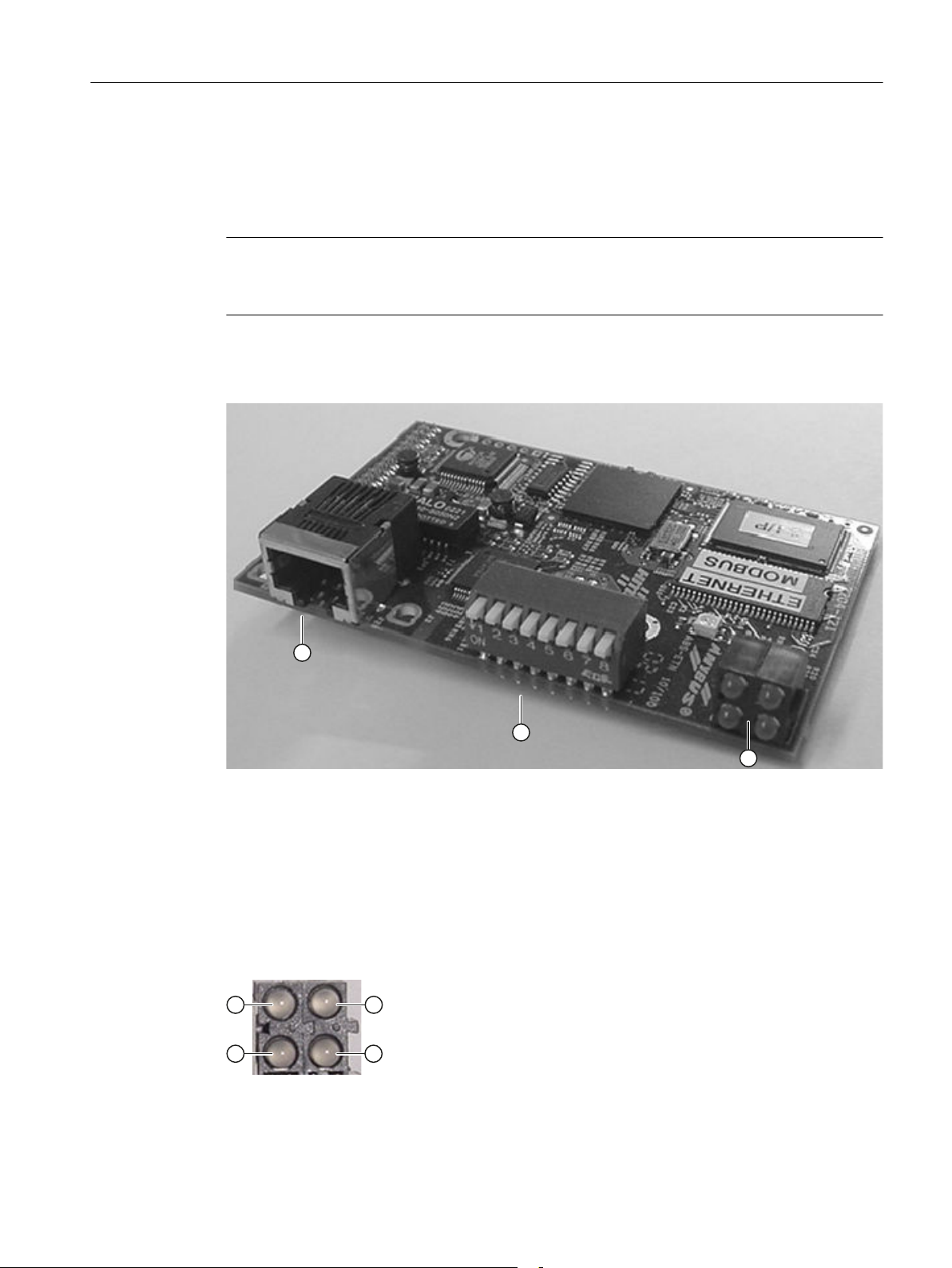
4.1.2 Anybus Modbus Ethernet Module
Description
Note
Network Usage
The Anybus™ Ethernet module is the only hardware that can be used for Network 2 .
The following figure shows the connector and status indicators on the Anybus™ Modbus™
Ethernet module. The DIP switches are not used for the NXGpro application.
Modbus Ethernet Communication
4.1 Description
1 RJ-45 connector
2 DIP switches (not used)
3 Status indicators
Figure 4-1 Anybus Ethernet Module
Status Indicators
The following figure shows the status indicators.
Figure 4-2 Status Indicators
NXGpro Communication
Function Manual, AB, A5E33486415A 75
Page 76

Modbus Ethernet Communication
4.1 Description
.Refer to Table
Table 4-1 Status Indicator Table
Status Indicator
(figure number)
1 Link present On The module has a link.
2 Module status Off No power applied to the module.
3 Network status Flashing Number of flashes = number of established Modbus/TCP
4 Data activity Flashing A packet is being received or transmitted.
Indication State Description
Status Indicator Table
Off The module does not sense a link.
Green The module is operating correctly.
Green, flashing The module has not been configured.
Red A major internal error has been detected.
Red, flashing A minor recoverable fault has been detected.
Green / red flashing The module is performing a power-on self-test.
to view explanation of the various status indicators
connections to the module
NXGpro Communication
76 Function Manual, AB, A5E33486415A
Page 77

4.2 Software Programming
This section provides details for user programming through the SOP.
The fixed register bits are defined by the drive's software by default. To reprogram the definition
of the bits, complete these steps:
Modbus Ethernet Communication
4.2 Software Programming
1. Set parameters using the procedure
controlled by the SOP
in Section
Fast Setup: control the drive using user-defined bits
Planning/Configuring.
2. Refer to the procedures detailed in this section to complete setup:
– programmable inputs to the drive
– programmable outputs from the drive
The following table shows how the fixed register bits correspond with programmable bits
available for use in the SOP (drctry.pro bits).
Table 4-2 Network 1 and 2: Fixed Register Bits
Pick list variable in 'Data to Drive Reg nn' menus Corresponding Drctry.pro bits Modbus Address
Fixed Reg Bits (network 1) CPU
(only valid on NXGpro software version 6.1 and
earlier)
Fixed Reg Bits (network 1) Anybus Network1FixedRegBit0_I ~ Network1FixedReg‐
Fixed Reg Bits (network 2) Network2FixedRegBit0_I ~ Network2FixedReg‐
Network1FixedRegBit0_I ~ Network1FixedReg‐
Bit15_I
Bit15_I
Bit15_I
40065 or 41025
41025
41025
4.2.1 Programmable Inputs to the Drive
Description
There are 64 input bits available for user programming through the SOP file. These bits can
be programmed to set or reset any other bits used within the SOP.
Programming Procedure
1. Locate the first data to drive register that is programmable using Table
between Drive Parameter ID and Communication Protocol Address
Assignment/Addressing
.
You will see that the first programmable data to drive register for network 1 is register 'Data
to Drive 03', which corresponds to parameter ID (9603).
2. Enter parameter ID (9603).
3. The pick list of data to drive variables will appear. Refer to Table
Variables and Scaling
in Section
Parameter Assignment/Addressing
drive pick list variables.
NXGpro Communication
Function Manual, AB, A5E33486415A 77
Correspondence
in Section
Parameter
Data to Drive Pick List
for a list of data to
Page 78

Modbus Ethernet Communication
4.2 Software Programming
4. Scroll through the pick list until you come to 'Net Input Flag 1' and press [ENTER]. This
setting uses the first 16 bits of the possible 64 bits.
Now the corresponding bits from the drctry.pro file can be used in the SOP, as shown below:
;Network1Flag0_I Use bit 0 for Stop bit
;Network1Flag1_I Use bit 1 for Run Forward bit
RunRequest_O = /Network1Flag0_I * Network1Flag1_I;Run drive using
bit 1,stop using bit 0
5. Select 'Net Input Flag 2' to use the second set of 16 bits, and so on.
Note
By choosing 'Data to Drive 03' as the write register, the PLC must now send 0x02 in register
'Data to Drive 03' to run the drive.
To stop the drive, the PLC must send 0x01 in register 'Data to Drive 03'.
The pick list variables and the corresponding programmable input bits are found in the following
tables for network 1 and 2, respectively.
Table 4-3 Network 1: Programmable input bits (parameter ID 9603-9664)
Example
Pick list variable in 'Data to Drive Reg nn' menus Related Drctry.pro bits
Net Input Flag 1 Network1Flag0_I ~ Network1Flag15_I
Net Input Flag 2 Network1Flag16_I ~ Network1Flag31_I
Net Input Flag 3 Network1Flag32_I ~ Network1Flag47_I
Net Input Flag 4 Network1Flag48_I ~ Network1Flag63_I
Table 4-4 Network 2: Programmable input bits (parameter ID 9703-9764)
Pick list variable in 'Data to Drive Reg nn' menus Related Drctry.pro bits
Net Input Flag 1 Network2Flag0_I ~ Network2Flag15_I
Net Input Flag 2 Network2Flag16_I ~ Network2Flag31_I
Net Input Flag 3 Network2Flag32_I ~ Network2Flag47_I
Net Input Flag 4 Network2Flag48_I ~ Network2Flag63_I
The following example shows how the network can be programmed to trip the input medium
voltage:
● The PLC writes to register 'Data to Drive 03' which is programmed to 'Net Input Flag 1'
using the procedure above.
● The SOP sets a flag bit that uses a digital output to trip input medium voltage, using the
following SOP source code:
;ExternalDigitalOutput01h_O Use digital output to trip input medium voltage
ExternalDigitalOutput01h_O = Network1FixedRegBit9_I;
NXGpro Communication
78 Function Manual, AB, A5E33486415A
Page 79

● The PLC writes the contents of 'Net Input Flag 1', bit 9 (Network1Flag9_I) to create an input
medium voltage trip.
4.2.2 Programmable Outputs from the drive
Description
There are 64 output bits available for user programming through the SOP file. These bits can
be programmed to set or reset any other bits used within the SOP.
Programming Procedure
Modbus Ethernet Communication
4.2 Software Programming
1. Locate the first data from drive register that is programmable using Table
between Drive Parameter ID and Communication Protocol Address
Assignment/Addressing
.
Correspondence
in Section
Parameter
You will see that the first programmable data from drive register for network 1 is register
'Data from Drive 03', which corresponds to parameter ID (9403).
2. Enter parameter ID (9403).
3. The pick list of data from drive variables will appear. Refer to Table
List Variables
in Section
Parameter Assignment/Addressing
for a list of data from drive pick
Data from Drive Pick
list variables.
4. Scroll through the pick list until you come to 'Net1 Out Reg 1' and press [ENTER]. This
setting uses the first 16 bits of the possible 64 bits.
5. Select 'Net1 Out Reg 2' to use the second set of 16 bits, and so on.
The pick list variables and the corresponding programmable output bits are found in the
following tables for network 1 and 2, respectively.
Table 4-5 Network 1: Programmable output bits (parameter ID 9403-9464)
Pick list variable in 'Data from Drive Reg nn' menus Related Drctry.pro bits
Net1 Out Reg 1 Network1Flag0_O ~ Network1Flag15_O
Net1 Out Reg 2 Network1Flag16_O ~ Network1Flag31_O
Net1 Out Reg 3 Network1Flag32_O ~ Network1Flag47_O
Net1 Out Reg 4 Network1Flag48_O ~ Network1Flag63_O
Table 4-6 Network 2: Programmable output bits (parameter ID 9503-9564)
Pick list variable in 'Data from Drive Reg nn' menus Related Drctry.pro bits
Net2 Out Reg 1 Network2Flag0_O ~ Network2Flag15_O
Net2 Out Reg 2 Network2Flag16_O ~ Network2Flag31_O
Net2 Out Reg 3 Network2Flag32_O ~ Network2Flag47_O
Net2 Out Reg 4 Network2Flag48_O ~ Network2Flag63_O
NXGpro Communication
Function Manual, AB, A5E33486415A 79
Page 80

Modbus Ethernet Communication
4.2 Software Programming
Example
The following example shows how the network can be programmed to detect a trip on the input
medium voltage:
● The PLC reads register 'Data from Drive 03', which is programmed to 'Net1 Out Reg 1'
using the procedure above.
● The SOP sets a flag bit that corresponds to a medium voltage low fault, using the following
SOP source code:
; Monitor medium voltage fault on the Modbus network
Network1Flag9_O = MediumVoltageLowFault_I;
● This example uses bit 9 of 'Net1 Out Reg 1', which is Network1Flag9_O, to set the network
flag true if the medium voltage low fault is active.
● The PLC reads the contents of 'Net1 Out Reg 1', bit 9 (Network1Flag9_O) to determine if
a medium voltage fault occured.
NXGpro Communication
80 Function Manual, AB, A5E33486415A
Page 81

Modbus Ethernet Communication
4.3 Parameter Assignment/Addressing
4.3 Parameter Assignment/Addressing
This section provides the following information for communication configuration and
programming:
● Drive parameter ID and corresponding communication protocol address
● Parameter tables:
– Network configuration parameters
– Network 1 configuration parameters
– Network 2 configuration parameters
● Pick list variable tables:
– Data from Drive variables
– Data to Drive variables
4.3.1 Correspondence between Drive Parameter ID and Communication Protocol Address
The following table provides drive parameter IDs and the corresponding Modbus™ addresses.
The following data is provided:
● Parameter ID
The drive parameter ID number to enter via the keypad or the ToolSuite.
● Modbus™ Address
A digital location provided by the Modbus™ Protocol, which stores values for use by the
master (PLC) and slave (Siemens drive) devices. To establish functional communication
between the PLC and the drive via the drive's Modbus™ connection, the control software
in the drive must be configured to know what certain addresses are used for.
● Data From Drive
Data that the PLC will receive from the drive to determine how the drive is functioning.
Each register contains a 16-bit digital representation of the status of a particular aspect of
drive functionality.
Some registers are fixed to track certain drive functions; others are programmable to track
any of a number of drive status choices.
● Data To Drive
Data that the PLC will send to the drive to control it.
Each register contains a 16-bit digital representation of the PLC's command for a particular
aspect of drive functionality.
Some registers are fixed to control certain functions; others are programmable to control
any of a number of drive function choices.
– Network 1 Data to drive can use either listed register range. There are 2 ranges available
to allow compatibility with the Anybus™ module on Network 2, and remain backward
compatible with the Modbus™ Ethernet implementation.
NXGpro Communication
Function Manual, AB, A5E33486415A 81
Page 82

Modbus Ethernet Communication
4.3 Parameter Assignment/Addressing
Table 4-7 Correspondence between Drive Parameter ID and Modbus Address
Network Parameter ID Description Default Contents Modbus Address
1 9401 Data From Drive 01 General Status
(not changeable)
1 9402 Data From Drive 02 Motor Speed
(not changeable)
1 9403 to 9464 Data From Drive 03 to 64 None 40003 to 40064
1 9601 Data To Drive 01 Fixed Register
Bits
(not changeable)
1 9602 Data To Drive 02 Velocity Demand
(not changeable)
1 9603 to 9664 Data To Drive 03 to 64 None When parameter "Ethernet Modbus Type"
2 9501 Data From Drive 01 General Status
(not changeable)
2 9502 Data From Drive 02 Motor Speed
(not changeable)
2 9503 to 9564 Data From Drive 03 to 64 None 40003 to 40064
2 9701 Data To Drive 01 Fixed Register
Bits (not change‐
able)
2 9702 Data To Drive 02 Velocity Demand
(not changeable)
2 9703 to 9764 Data To Drive 03 to 64 None 41027 to 41088
40001
40002
When parameter "Ethernet Modbus Type"
(9906) is set to "Internal CPU" and NXGpro
software version 6.1 and earlier is used:
40065
When parameter "Ethernet Modbus Type"
(9906) is set to "Anybus Module" or NXGpro
software 6.2 or later is used: 41025
When parameter "Ethernet Modbus Type"
(9906) is set to "Internal CPU" and NXGpro
software version 6.1 and earlier is used:
40066
When parameter "Ethernet Modbus Type"
(9906) is set to "Anybus Module" or NXGpro
software 6.2 or later is used: 41026
(9906) is set to "Internal CPU" and NXGpro
software version 6.1 and earlier is used:
40067 to 40128
When parameter "Ethernet Modbus Type"
(9906) is set to "Anybus Module" or NXGpro
software 6.2 or later is used:
41027 to 41088
40001
40002
41025
41026
NXGpro Communication
82 Function Manual, AB, A5E33486415A
Page 83

Modbus Ethernet Communication
4.3 Parameter Assignment/Addressing
4.3.2 Parameter Tables
Network Parameters
Table 4-8 Network Control Menu (9943)
Parameter ID Unit Default Min Max Description
Net Control Type 9944 SOP Set bit definition:
● SOP
● Fixed
Start Stop Control 9945 Maintained Set Start/Stop bit inputs:
● Maintained
● Momentary
Table 4-9 Network 1 to 2 Register Copy (9946)
Parameter ID Unit Default Min Max Description
Net 1 to 2 reg. copy 9946 Function Copy Network 1 registers to Network 2
registers.
Network 1 Parameters
Table 4-10 Network 1: Configure Menu (9900)
Parameter ID Unit Default Min Max Description
Network 1 Type 9901 None Designate the type of external network connected to
the drive:
● None
● Modbus
● DeviceNet
● Profibus
● Ethernet Modbus
● ControlNet
● Ethernet I/P
Ethernet Modbus
Type
(only valid for
NXGpro software
version 6.1 and ear‐
lier)
9906 Internal
(CPU)
Select the type of Modbus Ethernet connection to the
drive:
● Internal (CPU)
● Anybus Module
NXGpro Communication
Function Manual, AB, A5E33486415A 83
Page 84

Modbus Ethernet Communication
4.3 Parameter Assignment/Addressing
Table 4-11 Network 1: Configure Parameters Menu (9902)
Parameter ID Unit Default Min Max Description
Velocity Units 9080 % Designate the units for velocity values from
the drive:
● %
● RPM
● Hz
Demand Scalar 9912 1 -125 125 Set the scalar for input demand reference
from the network.
Aux Demand Scalar 9913 1 -125 125 Set the auxiliary scalar for input demand
reference from the network.
Network Timeout 9934 0 0 65535 Set the timeout for network determined to
be non-responsive.
Table 4-12 Network 1: TCP/IP Setup Menu (9300) when "Ethernet Modbus Type" (9906) is set to "Internal CPU"
1
Parameter ID Unit Default Min Max Description
IP Address 9310 172.16.20.16 Set the system TCP/IP address.
Subnet Mask 9320 255.255.0.0 Set the system TCP/IP subnet mask.
Gateway Address 9330 172.16.1.1 Set the system TCP/IP gateway address.
1
Only valid for NXGpro software version 6.1 and earlier
Table 4-13 Network 1: TCP/IP Setup Menu (9902) when "Ethernet Modbus Type" (9906) is set to "Anybus Module"
1,2
Parameter ID Unit Default Min Max Description
IP Address 9960 172.16.20.18 Set the system TCP/IP address.
Subnet Mask 9961 255.255.0.0 Set the system TCP/IP subnet mask.
Gateway Address 9962 172.17.1.1 Set the system TCP/IP gateway address.
1
NXGpro software version 6.1 and earlier uses this table or the preceeding table specifiying TCP/IP parameters.
2
NXGpro software version 6.2 and greater uses only this table.
Table 4-14 Network 1: Register Data from Drive Menu (9400)
Parameter ID Unit Default Min Max Description
Data From Drive 01 9401 General Sta‐
tus
Register data from drive parameter 1.
Register is not programmable.
Data From Drive 02 9402 Motor Speed Register data from drive parameter 2.
Register is not programmable.
Data From Drive 03 to 64 9403 to
9464
None Register data from drive parameters 3 to 64.
Registers are programmable.
NXGpro Communication
84 Function Manual, AB, A5E33486415A
Page 85

Modbus Ethernet Communication
4.3 Parameter Assignment/Addressing
Table 4-15 Network 1: Register Data to Drive Menu (9600)
Parameter ID Unit Default Min Max Description
Data To Drive Reg 01 9601 Fixed Reg
Bits
Data To Drive Reg 02 9602 Velocity De‐
mand
Data To Drive Reg 03 to 64 9603 to
9664
None Register data to drive parameters 3 to 64.
Register data to drive parameter 1.
Register is not programmable.
Register data to drive parameter 2.
Register is not programmable.
Registers are programmable.
Network 2 Parameters
Table 4-16 Network 2: Configure Menu (9914)
Parameter ID Unit Default Min Max Description
Network 2 Type 9915 None Designate the type of external network connected to the
drive:
● None
● Modbus
● DeviceNet
● Profibus
● Ethernet Modbus
● ControlNet
● Ethernet I/P
Table 4-17 Network 2: Configure Parameters Menu (9916)
Parameter ID Unit Default Min Max Description
Velocity Units 9924 Designate the units for velocity values
from the drive:
● %
● RPM
● Hz
Demand Scalar 9926 1 -125 125 Set the scalar for input demand reference
from the network.
Aux Demand Scalar 9927 1 -125 125 Set the auxiliary scalar for input demand
reference from the network.
Network Timeout 9935 0 0 65535 Set the timeout for network determined to
be non-responsive.
IP Address 9936 172.16.20.17 Set the system TCP/IP address.
Subnet Mask 9937 255.255.0.0 Set the system TCP/IP subnet mask.
Gateway Address 9938 172.17.1.1 Set the system TCP/IP gateway address.
NXGpro Communication
Function Manual, AB, A5E33486415A 85
Page 86

Modbus Ethernet Communication
4.3 Parameter Assignment/Addressing
Table 4-18 Network 2: Register Data from Drive Menu (9500)
Parameter ID Unit Default Min Max Description
Data From Drive 01 9501 General Sta‐
tus
Data From Drive 02 9502 Motor Speed Register data from drive parameter 2.
Data From Drive 03 to 64 9503 to
9564
Table 4-19 Network 2: Register Data to Drive Menu (9700)
Parameter ID Unit Default Min Max Description
Data To Drive Reg 01 9701 Fixed Reg
Data To Drive Reg 02 9702 Velocity De‐
Data To Drive Reg 03 to 64 9703 to
9764
None Register data from drive parameters 3 to 64.
Bits
mand
None Register data to drive parameters 3 to 64.
Register data from drive parameter 1.
Register is not programmable.
Register is not programmable.
Registers are programmable.
Register data to drive parameter 1.
Register is not programmable.
Register data to drive parameter 2.
Register is not programmable.
Registers are programmable.
4.3.3 Pick List Variable Tables
Table 4-20 Data from Drive Pick List Variables
Name
None None None None None None
Man Id None None None None Refer to Appendix
General Status 2001 None None Bit Field
Manual ID Unit Scaling 16 Bit Data
Type
Notes
● Bit 0: Fault
● Bit 1: Alarm
● Bit 2: Running Forward
● Bit 3: Running Reverse
● Bit 4: Drive Ready
● Bit 5: Start/Stop Control From Network
● Bit 6: Speed Reference From Network
● Bit 7: At Speed Reference
● Bit 8: Speed In Percent
● Bit 9: Speed In RPM
● Bit 10: Speed In Hz
● Bit 11: Reserved for future use
● Bit 12: Reserved for future use
● Bit 13: Reserved for future use
● Bit 14: Reserved for future use
● Bit 15: Reserved for future use
Internal Drive Network
NXGpro Communication
86 Function Manual, AB, A5E33486415A
Page 87
Modbus Ethernet Communication
4.3 Parameter Assignment/Addressing
Name
Motor Voltage 2100 Volts /1 Unsigned
Total Current 2190 Amps /1 Unsigned
Output Power 2230 KW /1 Signed
Motor Speed 2014 % /10 Unsigned
Speed Demand 2060 % /100 Unsigned
Speed Reference 2010 % /100 Unsigned
Heartbeat 2220 None None Unsigned 1 count per millisecond
Drive State 2210 None None Unsigned
Inp RMS Current 2130 Amps /1 Unsigned
Input Frequency 2140 Hz /100 Unsigned
Input Power Avg 2250 KW /1 Unsigned
Net1 Out Reg 1 2002 None None Bit Field Network1Flag0_I - Network1Flag15_I
Net1 Out Reg 2 2003 None None Bit Field Network1Flag16_I - Network1Flag31_I
Net1 Out Reg 3 2004 None None Bit Field Network1Flag32_I - Network1Flag37_I
Net1 Out Reg 4 2005 None None Bit Field Network1Flag48_I - Network1Flag63_I
Net2 Out Reg 1 2006 None None Bit Field Network2Flag0_I - Network2Flag15_I
Net2 Out Reg 2 2007 None None Bit Field Network2Flag16_I - Network2Flag31_I
Net2 Out Reg 3 2008 None None Bit Field Network2Flag32_I - Network2Flag37_I
Net2 Out Reg 4 2009 None None Bit Field Network2Flag48_I - Network2Flag63_I
Torque Current 2150 Amps /1 Unsigned
Magnetizing Cur 2170 Amps /1 Unsigned
Motor Flux 2015 % /100 Unsigned
Motor Torque 2160 % /100 Unsigned
Flux Reference 2011 % /100 Unsigned
Input Voltage 2120 Volts /1 Unsigned
Inp Power Factor 2012 % /100 Unsigned
Input KVars 2013 KVAR /1 Unsigned
Max Available Output
Volts
Hottest Cell Temp 2017 % /100 Unsigned Duty Cycle % of Hottest Cell
Manual ID Unit Scaling 16 Bit Data
Type
RPM /1
Hz /10
2016 Volts /1 Unsigned
Notes
● 0 = Off
● 1 = Magnetizing
● 2 = Spinning Load
● 3 = Autotune
● 4 = Run
● 5 = Stop
● 6 = Coast
● 7 = Up Transfer
● 8 = Down Transfer
NXGpro Communication
Function Manual, AB, A5E33486415A 87
Page 88

Modbus Ethernet Communication
4.3 Parameter Assignment/Addressing
Name
Mux1 Echo None None None None Refer to Appendix
Mux1 Data
Mux2 Echo
Mux2 Data
Mux3 Echo
Mux3 Data
Mux4 Echo
Mux4 Data
Mux5 Echo
Mux5 Data
Mux6 Echo
Mux6 Data
Mux7 Echo
Mux7 Data
Mux8 Echo
Mux8 Data
Wago Inputs 1-16 2650 None None Bit Field ExternalDigitalInput01a_I - ExternalDigita‐
Wago Inputs 17-32 2651 None None Bit Field ExternalDigitalInput03a_I - ExternalDigita‐
Wago Inputs 33-48 2652 None None Bit Field ExternalDigitalInput05a_I - ExternalDigita‐
Wago Inputs 49-64 2653 None None Bit Field ExternalDigitalInput07a_I - ExternalDigita‐
Wago Inputs 65-80 2654 None None Bit Field ExternalDigitalInput09a_I - ExternalDigita‐
Wago Inputs 81-96 2655 None None Bit Field ExternalDigitalInput11a_I - ExternalDigita‐
Wago Outputs 1-16 2656 None None Bit Field ExternalDigitalOutput01a_O - ExternalDigi‐
Manual ID Unit Scaling 16 Bit Data
Type
Notes
Multiplexer (MUX) Data
Registers
lInput01h_I
ExternalDigitalInput02a_I - ExternalDigita‐
lInput02h_I
lInput03h_I
ExternalDigitalInput04a_I - ExternalDigita‐
lInput04h_I
lInput05h_I
ExternalDigitalInput06a_I - ExternalDigita‐
lInput06h_I
lInput07h_I
ExternalDigitalInput08a_I - ExternalDigita‐
lInput08h_I
lInput09h_I
ExternalDigitalInput10a_I - ExternalDigita‐
lInput10h_I
lInput11h_I
ExternalDigitalInput12a_I - ExternalDigita‐
lInput12h_I
talOutput01h_O
ExternalDigitalOutput02a_O - ExternalDigi‐
talOutput02h_O
NXGpro Communication
88 Function Manual, AB, A5E33486415A
Page 89
Modbus Ethernet Communication
4.3 Parameter Assignment/Addressing
Name
Wago Outputs 17-32 2657 None None Bit Field ExternalDigitalOutput03a_O - ExternalDigi‐
Wago Outputs 33-48 2658 None None Bit Field ExternalDigitalOutput05a_O - ExternalDigi‐
Wago Outputs 49-64 2659 None None Bit Field ExternalDigitalOutput07a_O - ExternalDigi‐
PFD1 None None None None Refer to Appendix
PFD2
PFD3
PFD4
Drive Losses 2161 % /100 Unsigned
Excessive Reactive
Current
Speed Droop Percent 2163 % /100 Unsigned
Sync Motor Field Ref 2164 % /100 Unsigned
Avail Reactive Current 3653 % /100 Unsigned
Drive Efficiency 2168 % /100 Unsigned
Ids Ref Current 2276 % /100 Unsigned
Manual ID Unit Scaling 16 Bit Data
Type
2162 % /100 Unsigned
Notes
talOutput03h_O
ExternalDigitalOutput04a_O - ExternalDigi‐
talOutput04h_O
talOutput05h_O
ExternalDigitalOutput06a_O - ExternalDigi‐
talOutput06h_O
talOutput07h_O
ExternalDigitalOutput08a_O - ExternalDigi‐
talOutput08h_O
Parameter Read/Write
NXGpro Communication
Function Manual, AB, A5E33486415A 89
Page 90

Modbus Ethernet Communication
4.3 Parameter Assignment/Addressing
Table 4-21 Data to Drive Pick List Variables
Name
None None None None None
Fixed Reg Bits None None Bit Field When parameter 'Net Control Type' (9945) is set
Velocity Demand Hz /10 Signed Speed Demand
Auxiliary Demand Hz /10 Signed Auxilary Speed Demand
Net Input Flag 1 None None Bit Field Network 1 SOP flags:
Net Input Flag 2 None None Bit Field Network 1 SOP flags:
Net Input Flag 3 None None Bit Field Network 1 SOP flags:
Net Input Flag 4 None None Bit Field Network 1 SOP flags:
Ratio % % / 100 Signed
Forward Max Lim % / 10000 or
Reverse Max Lim % / 10000 or
Unit Scaling 16 Bit Data
Type
RPM 1
% /10
RPM 1
% /10
Unsigned
% / 100
Unsigned
% / 100
Notes
to 'SOP' the bits will be used in the SOP to control
drive functions.
When parameter 'Net Control Type' (9945) is set
to 'Fixed' the bits will be defined as follows in the
control software.
● Bit 0: Run Forward
● Bit 1: Run Reverse
● Bit 2: Fault Reset
● Bit 3: Stop
● Bit 4: Reserved
● Bit 5: Start/Stop Control From Network
● Bit 6: Speed Command From Network
● Bit 7 - 15: Reserved for future assignment
Network1Flag0_I ~ Network1Flag15_I
Network 2 SOP flags:
Network2Flag0_I ~ Network2Flag15_I
Network1Flag16_I ~ Network1Flag31_I
Network 2 SOP flags:
Network2Flag16_I ~ Network2Flag31_I
Network1Flag32_I ~ Network1Flag47_I
Network 2 SOP flags:
Network2Flag32_I ~ Network2Flag47_I
Network1Flag48_I ~ Network1Flag63_I
Network 2 SOP flags:
Network2Flag48_I ~ Network2Flag63_I
NXGpro Communication
90 Function Manual, AB, A5E33486415A
Page 91
Modbus Ethernet Communication
4.3 Parameter Assignment/Addressing
Name
Forward Acc Time Seconds / 10 Unsigned
Forward Dec Time Seconds / 10 Unsigned
Reverse Acc Time Seconds / 10 Unsigned
Reverse Dec Time Seconds / 10 Unsigned
Net Input Pulse None None Unsigned
Forward Min Lim % / 10000 or
Reverse Min Lim % / 10000 or
Torque Limit % / 10000 or
MUX1 Id None None None Refer to Appendix
MUX2 Id
MUX3 Id
MUX4 Id
MUX5 Id
MUX6 Id
MUX7 Id
MUX8 Id
PTD1 None None None Refer to Appendix
PTD2
PTD3
PTD4
Parallel Cmd 1 None None Unsigned
Torque Demand % / 1000 Unsigned
PVCL Demand % / 100 Unsigned
Flux Demand % / 100 Unsigned
Node Count None None Unsigned
Node Index None None Unsigned
Torque Acc Time Seconds / 100 Unsigned
Torque Dec Time Seconds / 100 Unsigned
Torque Offset None / 1000 Unsigned
Torque Scalar None / 1000 Unsigned
Vars Command % / 1000 Unsigned
No Load I Scalar None / 1000 Unsigned
Avg Field Cur Amps / 10000 Unsigned
Manual Ids Demand % / 1000 Unsigned
Avg Ids Ref Amps /10000 Unsigned
Unit Scaling 16 Bit Data
Type
Unsigned
% / 100
Unsigned
% / 100
Unsigned
% / 100
Notes
isters
Multiplexer (MUX) Data Reg‐
Parameter Read/Write
NXGpro Communication
Function Manual, AB, A5E33486415A 91
Page 92

Modbus Ethernet Communication
4.4 Planning/Configuring
4.4 Planning/Configuring
This section describes the setup methods available for communication. The following topics
are explained:
● Fast setup procedures
● Network interfaces
● Network setup procedure
● Network status detection
● An example to illustrate the setup procedure.
Note
Fast setup procedures allow setup of a Network 1 interface with a minimum of detail.
4.4.1 Fast Setup: Control the drive using the default configuration
To control the drive using the default configuration, you must send commands to the drive's
'fixed reg bits' location. This location is register 'Data to Drive 01' as provided in Table
Correspondence between Drive Parameter ID and Communication Protocol Address
Section
To control the drive from a PLC using the default configuration, complete the following steps.
1. Set parameter 'Network 1 Type' (9901) to "Ethernet Modbus". This setup assumes that an
2. Verify the network settings for the parameters 'Subnet Mask' and 'Gateway Address' . Refer
3. Set parameter 'IP Address'. The IP address must be unique to the drive. Refer to Tables
4. Set parameter 'Net Control Type' (9944) to "Fixed". This sets the bits at register 'Data to
5. Add the following line to the SOP:
Parameter Assignment/Addressing
existing working TCP/IP network is established.
to Tables titled Network 1: TCP/IP Setup Menu. and Network 1: TCIP/IP Setup Menu
located in the previous section of this chapter to find the parameter numbers for the
'Gateway Address' and the 'Subnet Mask' based on the NXGpro software version and
hardware configuration.
titled Network 1: TCP/IP Setup Menu. and Network 1 : TCIP/IP Setup Menu located in the
previous section of this chapter to find the parameter number for the 'IP Address' based on
the NXGpro software version and hardware configuation.
Drive 01' where the fixed register bits are located. The fixed register bits are interpreted as
shown in the following table.
Network1RunEnable_O = TRUE;
.
in
Table 4-22 Default definitions of Fixed Register Bits
Bit Default Definition
Network1FixedRegBit0_I Run forward
Network1FixedRegBit1_I Run reverse
NXGpro Communication
92 Function Manual, AB, A5E33486415A
Page 93

Modbus Ethernet Communication
4.4 Planning/Configuring
Bit Default Definition
Network1FixedRegBit2_I Fault reset
Network1FixedRegBit3_I Stop1
Network1FixedRegBit4_I Reserved
Network1FixedRegBit5_I Start stop control from network
Network1FixedRegBit6_I Speed commanded from network
Network1FixedRegBit7_I
Network1FixedRegBit8_I
Network1FixedRegBit9_I
Network1FixedRegBit10_I
Network1FixedRegBit11_I
Network1FixedRegBit12_I
Network1FixedRegBit13_I
Network1FixedRegBit14_I
Network1FixedRegBit15_I
1
Network1FixedRegBit3_I functions as a drive stop control bit only if parameter 'Start Stop Control'
(9945) is set to "Momentary". Otherwise this bit is reserved.
Reserved for future assignment
Note
To run the drive, the PLC must send 0x21 to register 'Data to Drive 01'. This hexadecimal value
sets bit 0 (run) and bit 5 (start/stop control from network).
To stop the drive, the PLC must send 0x08 or 0x00 to register 'Data to Drive 01'.
4.4.2 Fast Setup: Monitor drive status and speed feedback
To read status data from the drive, complete the following steps:
1. Set parameter 'Network 1 Type' (9901) to "Ethernet Modbus". This setup assumes that an
existing working TCP/IP network is established.
2. Verify the network settings for the parameters 'Subnet Mask' and 'Gateway Address' . Refer
to Tables titled Network 1: TCP/IP Setup Menu. and Network 1: TCIP/IP Setup Menu
located in the previous section of this chapter to find the parameter numbers for the
'Gateway Address' and the 'Subnet Mask' based on the NXGpro software version and
hardware configuration.
3. Set parameter 'IP Address'. The IP address must be unique to the drive. Refer to Tables
titled Network 1: TCP/IP Setup Menu. and Network 1 : TCIP/IP Setup Menu located in the
previous section of this chapter to find the parameter number for the 'IP Address' based on
the NXGpro software version and hardware configuation.
NXGpro Communication
Function Manual, AB, A5E33486415A 93
Page 94
Modbus Ethernet Communication
4.4 Planning/Configuring
4. Set parameter 'Velocity Units' (9080) to the desired motor speed units.
5. Refer to the Table
Protocol Address
Correspondence between Drive Parameter ID and Communication
in Section
Parameter Assignment/Addressing
to obtain the addresses
for general status (Data from Drive 01) and motor speed feedback (Data from Drive 02)
from the drive.
– 'Data from Drive 01' (9401) is read by sending the read register request in address
40001.
– 'Data from Drive 02' (9402) is read by sending the read register request in address
40002, and so on.
The general drive status bits found in register 'Data from Drive 01' are defined in the following
table.
Table 4-23 Default definitions of General Status Bits
Bit number Meaning in drive control soft‐
ware
0 Fault
1 Alarm
2 RunningForward
3 RunningReverse
4 DriveReady
5 StartStopControlFromNetwork
6 SpeedFromNetwork
7 AtSpeedReference
8 SpeedInPercent
9 SpeedInRPM
10 SpeedInHz
11 Reserved for future use
12 Reserved for future use
13 Reserved for future use
14 Reserved for future use
15 Reserved for future use
Value
0 = False; 1 = True
Note
You cannot reprogram the drive's default interpretation of output bits.
Refer to
Network Setup Procedure
for details on how to read other drive data.
NXGpro Communication
94 Function Manual, AB, A5E33486415A
Page 95

Modbus Ethernet Communication
4.4 Planning/Configuring
4.4.3 Fast Setup: Send a motor speed setting to the drive
1. Using parameter 'Velocity Units' (9080), set the desired speed units to be sent to the drive,
to one of the following options:
– %
– RPM
– Hertz
2. The PLC needs to send the desired speed setting to the drive in register 'Data to Drive 02' .
This register is reserved to hold speed settings only, as noted in Table
between Drive Parameter ID and Communication Protocol Address
Correspondence
in Section
Parameter
Assignment/Addressing.
3. Send 0x61 in register 'Data to Drive 01' . The motor now accepts the speed setting from
the PLC.
4.4.4 Fast Setup: Control the drive using user-defined bits controlled by the SOP
To control the drive using non-default configuration, you must redefine the fixed register bits
at register 'Data to Drive 01'.
Note
The 'fixed reg bits' location is fixed at register 'Data to Drive 01', whether the default
configuration is used or not.
You cannot reprogram the 'fixed reg bits' location.
You can reprogram the definition of the bits at this address.
To control the drive this way, complete the following steps.
1. Set parameter 'Network 1 Type' (9901) to "Ethernet Modbus". This setup assumes that an
existing working TCP/IP network is established.
2. Verify the network settings for the parameters 'Subnet mask' and 'Gateway address' . Refer
to Tables titled Network 1: TCP/IP Setup Menu. and Network 1: TCIP/IP Setup Menu
located in the previous section of this chapter to find the parameter numbers for the
'Gateway Address' and the 'Subnet Mask' based on the NXGpro software version and
hardware configuration.
3. Set parameter 'IP Address'. The IP address must be unique to the drive. Refer to Tables
titled Network 1: TCP/IP Setup Menu. and Network 1: TCIP/IP Setup Menu located in the
previous section of this chapter to find the parameter number for the 'IP Address' based on
the NXGpro software version and hardware configuation.
4. Set parameter 'Net Control Type' (9944) to "SOP". This makes the definitions of the fixed
register bits in register 'Data to Drive 01' programmable.
NXGpro Communication
Function Manual, AB, A5E33486415A 95
Page 96
(WKHUQHW0RGEXV'HYLFH
&URVVRYHUFDEOH
DQGFRXSOHU
1;*SUR&RQWURO
Modbus Ethernet Communication
4.4 Planning/Configuring
5. Next, set up the drive to correspond with the bits you want to use in the SOP. Refer to
Section
Software Programming
variable, and use the procedures detailed in this section to complete set up.
6. To enable speed settings from the network, add the following line to the SOP file:
RawDemandNetwork1_O = true;
See also
Software Programming (Page 77)
4.4.5 Network Interfaces
The NXGpro Control is equipped with a high performance 32-bit Ethernet chipset which is fully
compliant with IEEE 802.3 100 MBPS CSMA/CD standards.
● It uses a dedicated standard RJ-45 port located on the front of the CPU board that supports
Network 1.
● The Anybus™ Modbus™ Ethernet module uses a standard RJ-45 port located on the
module to support Network 2.
to find the bits and locate the associated keypad pick list
Possible configurations for Ethernet communication between an Modbus™ Ethernet device
and the NXGpro Control software are described below. Choose a configuration based on the
site infrastructure.
Direct Ethernet Connection
Direct connection is intended for a single Modbus™ Ethernet device that is connected to the
drive using an Ethernet crossover cable. This cable allows direct connection to the drive without
a hub or server.
Figure 4-3 Direct Modbus Ethernet Communication Connection
96 Function Manual, AB, A5E33486415A
The following hardware is required for this connection method:
● Crossover patch cable
● Coupler
NXGpro Communication
Page 97
Multiple Drive LAN Ethernet Connection
(WKHUQHW,3'HYLFH
+XE
1;*SUR&RQWURO
1;*SUR&RQWURO
To use the LAN connection to control one or more drives on an existing network complete the
following steps:
● Assign a unique IP address to each drive.
● Set the menu items of the TCP/IP Setup Menu (9300) for each drive.
● For Network 1, set the following menu items based on the settings unique to the network.
Verify the network settings for the parameters 'IP Address", 'Subnet Mask' and 'Gateway
Address'. Refer to Tables titled Network 1: TCP/IP Setup Menu. and Network 1 : TCIP/IP
Setup Menu located in the previous section of this chapter to find the parameter numbers
for "IP Address', 'Subnet Mask' and the 'Gateway Address' based on the NXGpro software
version and hardware configuration.
● For Network 2, set the following menu items based on the settings unique to the network:
– IP Address (9336)
– Subnet Mask (9337)
– Gateway Address (9338)
Modbus Ethernet Communication
4.4 Planning/Configuring
Refer to Table
Assignment/Addressing
Figure 4-4 Network Modbus™ Ethernet Communication Connection
Network 2 Configure Parameters Menu (9916)
of this chapter.
The following hardware is required for this connection method:
● EtherFast 10/100 hub
● Ethernet Cat5 cable
in Section
Parameter
NXGpro Communication
Function Manual, AB, A5E33486415A 97
Page 98

Modbus Ethernet Communication
4.4 Planning/Configuring
4.4.6 Network Setup Procedure
Note
Setup functions are contained in the Configure Parameters Menu (9902), which is a submenu
of the Communications Menu (9).
Access is security-controlled at level 7; you must enter the security code to access these
parameters.
Procedure
Refer to the
levels and codes.
Use the following procedure to complete network setup. Refer to Table
Menu (9902)
setup.
1. Select a protocol using parameter 'Network 1 Type' (9901). Scroll to "Ethernet/IP" and press
[ENTER]. The configuration parameters are viewable.
2. Set parameter 'Velocity Units' (9080) to the desired motor speed units for motor
commanded speed and motor feedback speed scaling.
3. Where necessary, set parameter 'Demand Scalar' (9912) to:
n
x command speed where –125 % to 125 %
4. Set parameter 'Aux Demand Scalar' (9913) if used.
5. Use Table
Address
to and receive commands from the network. The table provides all available addresses with
corresponding parameter ID as well as pre-programmed addresses, which provide basic
drive send and receive functionality and are not changeable.
NXGpro Control Operating Manual
for further information on security access
Configure Parameters
in Section
Parameter Assignment/Addressing
for the menus needed to complete
Correspondence between Drive Parameter ID and Communication Protocol
in Section
Parameter Assignment/Addressing
to program the drive to send data
6. Define the bits in the available addresses using one of the following methods:
NXGpro Communication
98 Function Manual, AB, A5E33486415A
Page 99

Modbus Ethernet Communication
4.4 Planning/Configuring
● Enter from a choice of variables in the pick lists. The pick lists in the menus contain the
most commonly used data variables. Refer to Section
for the pick lists.
Note
A pick list item can only be used once for each 'Data to Drive' register.
● For 'Data from Drive' registers, choose pick list option "Man Id" (manual ID) to manually
enter a variable that is not included in the pick lists, using the output data ID number. Use
the list of data IDs available in Appendix
corresponding ID number to enter the variable into the 'Data from Drive' register.
Note
The output data ID number is not the same as a parameter ID number.
Output Data IDs
Parameter Assignment/Addressing
to locate the variable and use the
● Custom program using the drive's SOP. Refer to Section
Note
The PLC can receive data from the drive without any changes to the SOP.
Only if you need to control the drive through the network will you need to set any flags in
the SOP.
See also
Output Data IDs (Page 277)
Software Programming (Page 112)
Set flags in the SOP for drive control through a network
Ensure the SOP file has the necessary code to enable control of the drive over a network:
1. To control the drive through a network by sending commands to the drive, the following
network control flag must be in the source code of the drive's SOP:
Network1RunEnable_O = TRUE;
2. To control the drive through a second network, the following network control flag must be
in the source code of the drive's SOP:
Network2RunEnable_O = TRUE;
Software Programming
for details.
4.4.7 Network Status Detection Setup
An SOP flag is available to show the network status:
● For network 1: Network1CommOk_I
● For network 2: Network2CommOk_I
The SOP flag is set to "1" (true) when the network connection is operating normally, and "0"
(false) when it is not operating normally.
NXGpro Communication
Function Manual, AB, A5E33486415A 99
Page 100

Modbus Ethernet Communication
4.4 Planning/Configuring
The network status cannot be automatically detected. Instead, a "Pulse Timeout" method is
used to set the network status flags.
The "Pulse Timeout" status detection must be set up in the menu system, and has to be
“strobed” by a network device that is communicating with the drive.
Procedure for Pulse Timeout Setup
1. Pick one of the 62 selectable "Data to Drive" registers and set the pick list item to "Net Input
Pulse".
2. Set parameter 'Network Timeout' (9934) for network 1 and (9935) for network 2, in the
'Config Parameters' menu, to a value (in seconds) to activate the network timeout. 0
seconds = disable timeout.
Pulse Timeout Operation
● A network device must set a unique (different) value into the "Net Input Pulse" register
before an internal timer reaches the "Network Timeout" value.
● If the network device writes a unique value, the network status flag is set to "1" and the
internal timer is reset.
● If the network device fails to write a unique value to the "Net Input Pulse" register before
the internal timer times to the value set by the "Network Timeout" parameter then the status
flag is set to "0".
4.4.8 Setup Example
Task
Set up network to indicate the following drive outputs on the PLC:
● general status
● motor speed
● output power
● number of active faults.
Procedure
Refer to Table
Address
register is changeable.
To indicate general status and motor speed:
1. The table shows that:
● 'Data from Drive 01' is not changeable; it is set to indicate general status. No action is
● 'Data from Drive 02' is not changeable; it is set to indicate motor speed. No action is required.
in Section
required.
Correspondence between Drive Parameter ID and Communication Protocol
Parameter Assignment/Addressing
to establish whether an address or
NXGpro Communication
100 Function Manual, AB, A5E33486415A
 Loading...