

Siemens SINAMICS IOP-2 Operating Instructions Manual


___________________
___________________
___________________
___________________
___________________
___________________
___________________
___________________
___________________
SINAMICS
Intelligent Operating Panel 2 (IOP-2)
Operating Instructions
Edition 04/2017, Firmware IOP-2 V2.0
04/2017, FW V2.0
A5E39549448B AA
Fundamental safety
instructions
1
Safety notes
2
Overview
3
Installation
4
Wizards menu
5
Control menu
6
Menu
7
Options
8
Technical data
9

Siemens AG
Division Digital Factory
Postfach 48 48
90026 NÜRNBERG
GERMANY
Document order number: (null)
Ⓟ
Copyright © Siemens AG 2017.
All rights reserved
Legal information
Warning notice system
DANGER
indicates that death or severe personal injury will result if proper precautions are not taken.
WARNING
indicates that death or severe personal injury may result if proper precautions are not taken.
CAUTION
indicates that minor personal injury can result if proper precautions are not taken.
NOTICE
indicates that property damage can result if proper precautions are not taken.
Qualified Personnel
personnel qualified
Proper use of Siemens products
WARNING
Siemens products may only be used for the applications described in the catalog and in the relevant technical
ambient conditions must be complied with. The information in the relevant documentation must be observed.
Trademarks
Disclaimer of Liability
This manual contains notices you have to observe in order to ensure your personal safety, as well as to prevent
damage to property. The notices referring to your personal safety are highlighted in the manual by a safety alert
symbol, notices referring only to property damage have no safety alert symbol. These notices shown below are
graded according to the degree of danger.
If more than one degree of danger is present, the warning notice representing the highest degree of danger will
be used. A notice warning of injury to persons with a safety alert symbol may also include a warning relating to
property damage.
The product/system described in this documentation may be operated only by
task in accordance with the relevant documentation, in particular its warning notices and safety instructions.
Qualified personnel are those who, based on their training and experience, are capable of identifying risks and
avoiding potential hazards when working with these products/systems.
Note the following:
documentation. If products and components from other manufacturers are used, these must be recommended
or approved by Siemens. Proper transport, storage, installation, assembly, commissioning, operation and
maintenance are required to ensure that the products operate safely and without any problems. The permissible
All names identified by ® are registered trademarks of Siemens AG. The remaining trademarks in this publication
may be trademarks whose use by third parties for their own purposes could violate the rights of the owner.
We have reviewed the contents of this publication to ensure consistency with the hardware and software
described. Since variance cannot be precluded entirely, we cannot guarantee full consistency. However, the
information in this publication is reviewed regularly and any necessary corrections are included in subsequent
editions.
for the specific
04/2017 Subject to change

Table of contents
1 Fundamental safety instructions .............................................................................................................. 7
2 Safety notes ............................................................................................................................................ 9
3 Overview............................................................................................................................................... 11
4 Installation ............................................................................................................................................ 19
5 Wizards menu ....................................................................................................................................... 27
6 Control menu ........................................................................................................................................ 33
7 Menu .................................................................................................................................................... 41
1.1 General safety instructions ....................................................................................................... 7
1.2 Industrial security ...................................................................................................................... 8
2.1 Warnings and cautions ............................................................................................................. 9
3.1 Introduction ............................................................................................................................. 11
3.2 Layout and functions ............................................................................................................... 12
3.3 Screen icons ........................................................................................................................... 15
3.4 Menu structure ........................................................................................................................ 17
4.1 Fitting the IOP-2 ...................................................................................................................... 19
4.2 Initial set-up ............................................................................................................................. 20
4.3 User definable labels on status screen ................................................................................... 24
4.4 Firmware upgrade ................................................................................................................... 25
5.1 Example Wizard ...................................................................................................................... 28
5.1.1 Basic commissioning with the IOP-2 ...................................................................................... 30
6.1 Setpoint ................................................................................................................................... 34
6.2 Reverse ................................................................................................................................... 34
6.3 Jog .......................................................................................................................................... 35
6.4 Custom Hand mode ................................................................................................................ 35
6.5 Startup in Hand mode ............................................................................................................. 37
6.6 HAND/AUTO disable .............................................................................................................. 38
7.1 Menu overview ........................................................................................................................ 41
7.2 Diagnostics ............................................................................................................................. 41
7.3 Parameters ............................................................................................................................. 45
7.4 Up/Download .......................................................................................................................... 48
7.5 Customer parameter sets ....................................................................................................... 49
Intelligent Operating Panel 2 (IOP-2)
Operating Instructions, 04/2017, FW V2.0, A5E39549448B AA
5

Table of contents
8 Options ................................................................................................................................................. 63
9 Technical data ...................................................................................................................................... 69
Index .................................................................................................................................................... 71
7.6 Extras Menu ........................................................................................................................... 51
8.1 Door mounting kit ................................................................................................................... 63
8.2 Hand-held device ................................................................................................................... 65
9.1 Technical specifications ......................................................................................................... 69
Intelligent Operating Panel 2 (IOP-2)
6 Operating Instructions, 04/2017, FW V2.0, A5E39549448B AA
1
1.1
General safety instructions
WARNING
Danger to life if the safety instructions and residual risks are not observed
WARNING
Danger to life or malfunctions of the machine as a result of incorrect or changed
parameterization
If the safety instructions and residual risks in the associated hardware documentation are
not observed, accidents involving severe injuries or death can occur.
• Observe the safety instructions given in the hardware documentation.
• Consider the residual risks for the risk evaluation.
As a result of incorrect or changed parameterization, machines can malfunction, which in
turn can lead to injuries or death.
• Protect the parameterization (parameter assignments) against unauthorized access.
• Respond to possible malfunctions by applying suitable measures (e.g. EMERGENCY
STOP or EMERGENCY OFF).
Intelligent Operating Panel 2 (IOP-2)
Operating Instructions, 04/2017, FW V2.0, A5E39549448B AA
7

Fundamental safety instructions
1.2
Industrial security
Note
Industrial security
Siemens provides products
secure operation of plants, systems, machines and networks.
In order to protect plants, systems, machines and networks against cyber threats, it is
necessary to implement
security concept. Siemens products and solutions only represent one component of such a
concept.
The customer is responsible for preventing unauthorized access to its plants, systems,
machines and networks
the enterprise network or the internet if and to the extent necessary and with appropriate
security measures (e.g. use of firewalls and network segmentation) in place.
Additionally, Siemens
account. For more information about industrial security, please visit:
Industrial security (
Siemens
secure. Siemens strongly recommends to apply product updates as soon as available and to
always use the latest product versions. Use of product versions that are no longer supported,
and failure to apply latest updates may increase customer
To stay informed about product updates, subscribe to the Siemens Industrial Security RSS
Feed at:
Industrial security (
WARNING
Danger to life as a result of unsafe operating states resulting from software manipulation
1.2 Industrial security
and solutions with industrial security functions that support the
– and continuously maintain – a holistic, state-of-the-art industrial
. Systems, machines and components should only be connected to
’ guidance on appropriate security measures should be taken into
http://www.siemens.com/industrialsecurity).
’ products and solutions undergo continuous development to make them more
’s exposure to cyber threats.
http://www.siemens.com/industrialsecurity).
Software manipulations (e.g. viruses, trojans, malware or worms) can cause unsafe
operating states in your system that may lead to death, serious injury, and property
damage.
• Keep the software up to date.
• Incorporate the automation and drive components into a holistic, state-of-the-art
industrial security concept for the installation or machine.
• Make sure that you include all installed products into the holistic industrial security
concept.
• Protect files stored on exchangeable storage media from malicious software by with
suitable protection measures, e.g. virus scanners.
Intelligent Operating Panel 2 (IOP-2)
8 Operating Instructions, 04/2017, FW V2.0, A5E39549448B AA
2
2.1
Warnings and cautions
Warnings and cautions
DANGER
Ensuring a safe and stable state
WARNING
The converter will stop if the IOP-2 is removed when in Hand mode
Note
•
•
During commissioning of the converter it is essential to ensure that the system is in a safe
and stable state, as some commissioning processes have the potential to start the motor.
Therefore it is important to secure any loads and ensure that should the motor start, no
potentially dangerous conditions exist.
When the IOP-2 is in Hand mode, that is, when the command source is switched to Hand
and all OFF and RUN commands are given via the IOP-2 buttons.
When in the Hand mode, if the IOP-2 is removed from the converter, the converter will stop
within a few seconds of the IOP-2 being removed.
Before removing the IOP-2, ensure that the IOP-2 is placed in AUTO mode and receiving
its command source from the PLC.
The IOP-2 can be fitted to and removed from the converter while power is applied.
The IOP-2 will set the USS PZD (P2012) length to 4 when connected to the converter.
Intelligent Operating Panel 2 (IOP-2)
Operating Instructions, 04/2017, FW V2.0, A5E39549448B AA
9

Safety notes
2.1 Warnings and cautions
Intelligent Operating Panel 2 (IOP-2)
10 Operating Instructions, 04/2017, FW V2.0, A5E39549448B AA

3
3.1
Introduction
Compatibility
Note
IOP functional support
•
•
– The selected functional group filtering of the parameters.
The Intelligent Operator Panel 2 (IOP-2) has been designed to enhance the interface and
communications capabilities of SINAMICS Inverters.
The IOP-2 connects to the Inverter through an RS232 interface. It has been designed to
automatically recognize the following devices from the SINAMICS range:
● SINAMICS G120 CU230P-2
● SINAMICS G120 CU240B-2
● SINAMICS G120 CU240E-2
● SINAMICS G120 CU250S-2
● SINAMICS G120C
● SINAMICS G120D-2 CU240D-2*
● SINAMICS G120D-2 CU250D-2*
● SINAMICS ET 200pro FC-2*
● SINAMICS G110D*
● SINAMICS G110M*
*Denotes Control Units that require the IOP-2 Hand-Held Kit to connect the IOP to the
Control Unit.
Hand-Held Kit order number: 6SL3255-0AA00-4HA1.
Optical cable order number: 3RK1922-2BP00
For information on firmware and language upgrades, please see
(Page 25).
Drives with SINAMICS firmware prior to version 4.4 will not be supported by the IOP-2.
Drives with GP firmware prior to version 3.4 are not fully supported by the IOP-2.
The actual menu structure and functionality of the IOP-2 will be influenced by the
following factors:
– The software version and type of Control Unit to which the IOP-2 is fitted.
– The firmware and software version of the IOP-2.
Firmware upgrade
Intelligent Operating Panel 2 (IOP-2)
Operating Instructions, 04/2017, FW V2.0, A5E39549448B AA
11
Overview
3.2
Layout and functions
Overview
3.2 Layout and functions
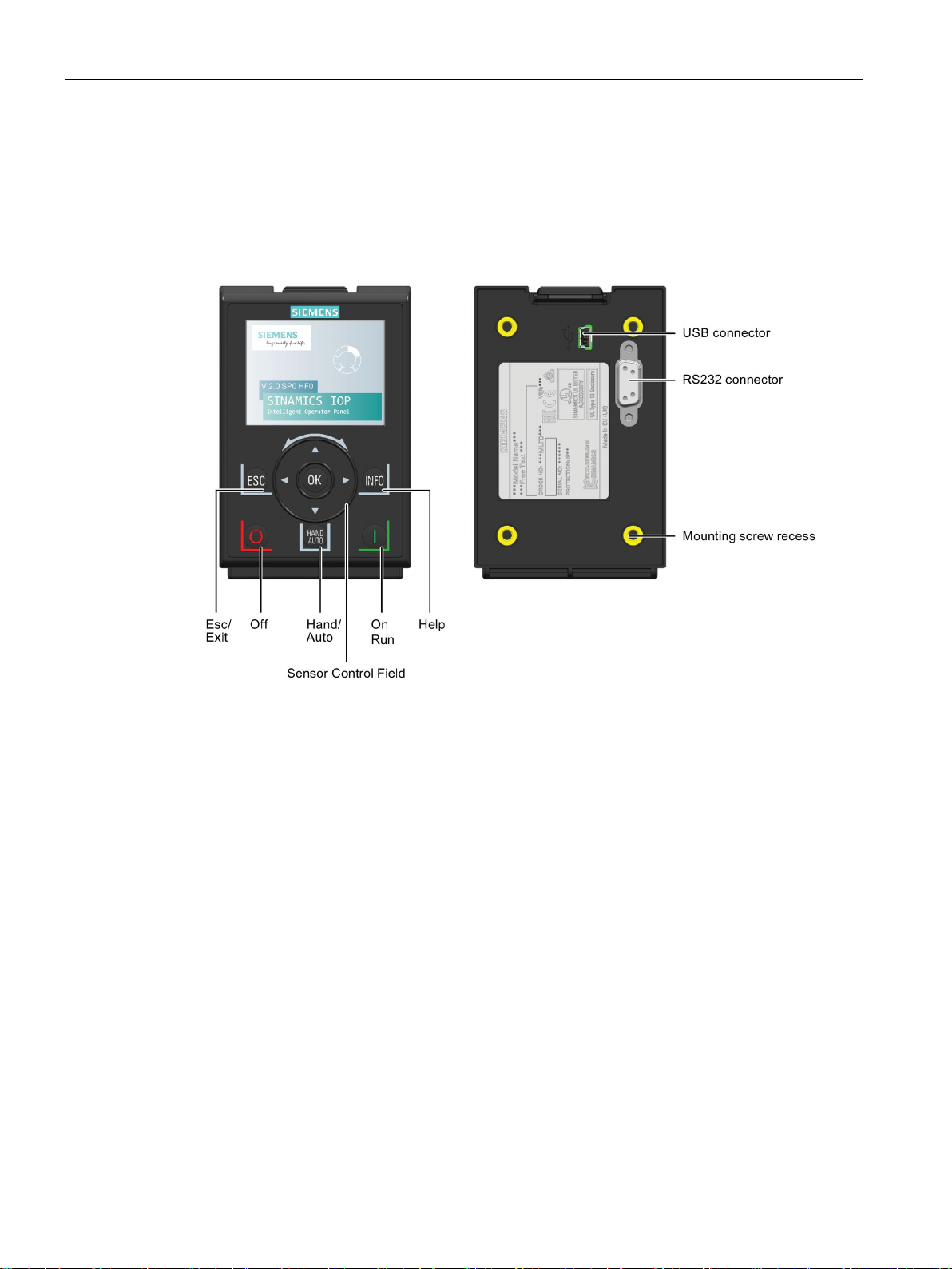
The physical layout of the IOP-2 is shown below:
Figure 3-1 Layout of the IOP-2
Intelligent Operating Panel 2 (IOP-2)
12 Operating Instructions, 04/2017, FW V2.0, A5E39549448B AA

Overview
Key
Function
When the converter is running in HAND mode, the motor stops when switched to AUTO.
When using the ESC key in the parameter editing mode, no data is saved unless the OK key is pressed first.
3.2 Layout and functions
The IOP-2 is operated by using a Sensor Control Field and five additional buttons. The
specific functions of the Sensor Control Field and buttons are shown in the table below.
Table 3- 1 Function of the IOP-2 controls
The Sensor Control Field has the following functions:
• In a menu, sliding your finger around the Sensor Control Field changes the selection.
• When a selection is highlighted, pressing the OK button in the centre of the Sensor Control Field
confirms the selection.
• When editing a parameter, sliding your finger around the Sensor Control Field changes the displayed
value; clockwise increases the value and anti-clockwise decreases the displayed value.
• When editing parameter or search values there is a choice to edit individual digits using the arrow keys
or an entire value using the Sensor Control Field. The speed with which you slide your finger around the
Sensor Control Field increases or descreases the speed of movement of the cursor.
• The Sensor Control Field has integrated arrows which can be used to navigate through the menus and
individual digits in the inputs fields.
The ON key has the following functions:
• In AUTO mode can be changed by pressing the HAND/AUTO key.
• In HAND mode the converter is started - the converter status icon starts turning.
Notes:
For Control Units with firmware versions less than 4.0:
When running in AUTO mode, HAND mode cannot be selected unless the converter is stopped.
For Control Units with firmware versions 4.0 or greater:
When running in AUTO mode, HAND mode can be selected and the motor will continue to run at the last
selected setpoint speed.
The OFF key has the following functions:
• If pressed for longer than 3 seconds the converter will perform an OFF2; the motor will then coast down
to a standstill. Note: 2 presses of the OFF key within 3 seconds will also perform and OFF2.
• If pressed for less than 3 seconds the following actions will be performed:
– If in AUTO mode the screen will display an information screen stating that the command sources is
AUTO and can be changed using the HAND/AUTO key. The converter will not be stopped.
– If in HAND mode the converter will perform an OFF1; the motor will come to a standstill in the ramp-
down time set in parameter P1121.
The ESC key has the following functions:
• If pressed for less than 3 seconds the IOP-2 returns to the previous screen or if a value has been edited,
the new value is not saved.
• If pressed longer than 3 seconds the IOP-2 returns to the status screen.
Intelligent Operating Panel 2 (IOP-2)
Operating Instructions, 04/2017, FW V2.0, A5E39549448B AA
13

Overview
Key
Function
Locking and unlocking the keypad
ESC
INFO
ESC
INFO
DEMO mode
3.2 Layout and functions
The INFO key has the following functions:
• Displays additional information for the currently selected item.
• Pressing the INFO key again will display the previous screen.
• Pressing the INFO key during power-up of the IOP-2 will place the IOP-2 in DEMO mode. To exit DEMO
mode, power-cycle the IOP-2.
The HAND/AUTO key switches the command source between HAND and AUTO mode.
• HAND sets the command source to the IOP-2.
• AUTO sets the command source to an external source, for example, fieldbus.
The keypad can only be locked once the power-up cycle has been completed. If the keys are
activated before the power-up cycle is completed, the IOP-2 will enter the DEMO mode.
To lock the IOP-2 keypad press
unlock the keypad press
DEMO mode allows the IOP-2 to be used for demonstration purposes without affecting the
converter to which it is connected. Menus can be navigated and functions selected, but all
communications with the converter are blocked to ensure that the converter does not react to
any commands issued from the IOP-2.
and
and
simultaneously for 3 seconds or more. To
simultaneously for 3 seconds or more.
To enter the DEMO mode it is necessary to do a long press of the ESC key or INFO key
during the power-up cycle. The IOP-2 must be power cycled again to exit the DEMO mode.
Intelligent Operating Panel 2 (IOP-2)
14 Operating Instructions, 04/2017, FW V2.0, A5E39549448B AA
Overview
3.3
Screen icons
Overview
Function
Icon
Remarks
controller
must be performed.
mode
Protection
condition
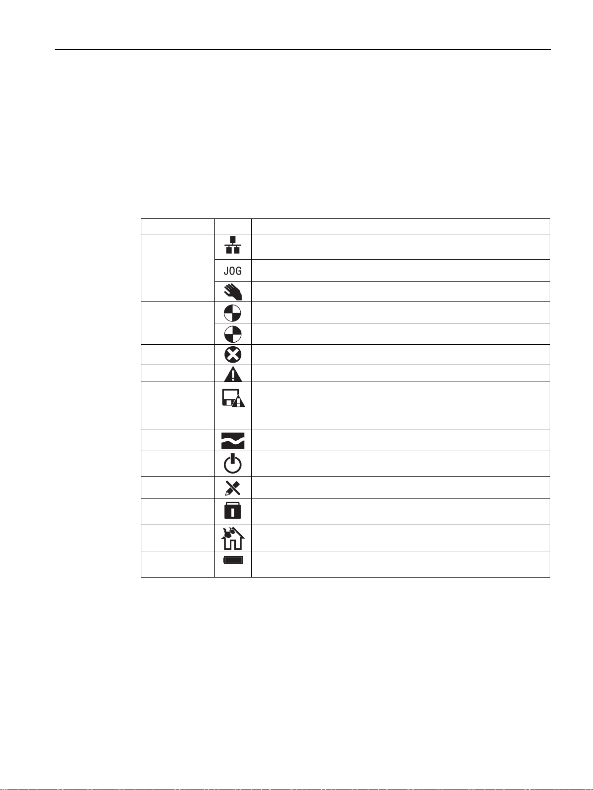
3.3 Screen icons
The IOP-2 displays a number of icons at the top right-hand edge of the display to indicate
various states or current conditions of the converter. These icons are explained in the table
below.
Table 3- 2 Screen icons
Command
source
Inverter status
Fault pending
Alarm pending
Saving to RAM
PID autotuning
Hibernation
Write Protection
Know How
ESM
Auto - the converter receives the command signals from the network
Displayed when the JOG function is active
Hand - the converter is under control of the IOP-2
Icon rotates when the motor is running
Indicates that all recent changes to parameters have been saved in RAM
only. In the event of a power failure, then all recent changes saved to
RAM will be lost. To prevent loss of parameter data a RAM-to-ROM save
Parameters cannot be modified.
Parameters cannot be viewed or modified.
Essential Services Mode
Intelligent Operating Panel 2 (IOP-2)
Operating Instructions, 04/2017, FW V2.0, A5E39549448B AA
Battery
The battery status is only shown when the IOP-2 Hand-held kit is used.
15
Overview
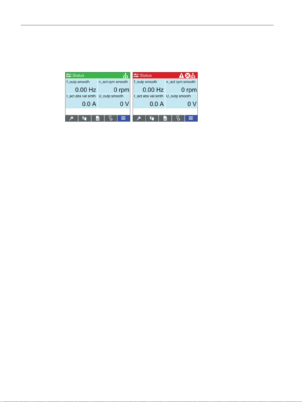
Screen faults and alarm indicators
Use of screen colours
Red
Error status: Indicates a fault is active and the Control Unit is in an error condition.
White
Neutral status: The IOP-2 has no connection to the Control Unit.
Green
Run status: The converter is running with no active faults. Active alarms will be
displayed on the status bar.
Blue
Blue denotes the selected item on the screen.
3.3 Screen icons
When a fault or an alarm is active on the converter the top label on the screen will turn red.
The top label will remain red until the fault or warning has been acknowledged or rectified.
Figure 3-2 Fault and alarm notifications
A brief explanation of the use of the different colours on the screen is given below:
Intelligent Operating Panel 2 (IOP-2)
16 Operating Instructions, 04/2017, FW V2.0, A5E39549448B AA
Overview
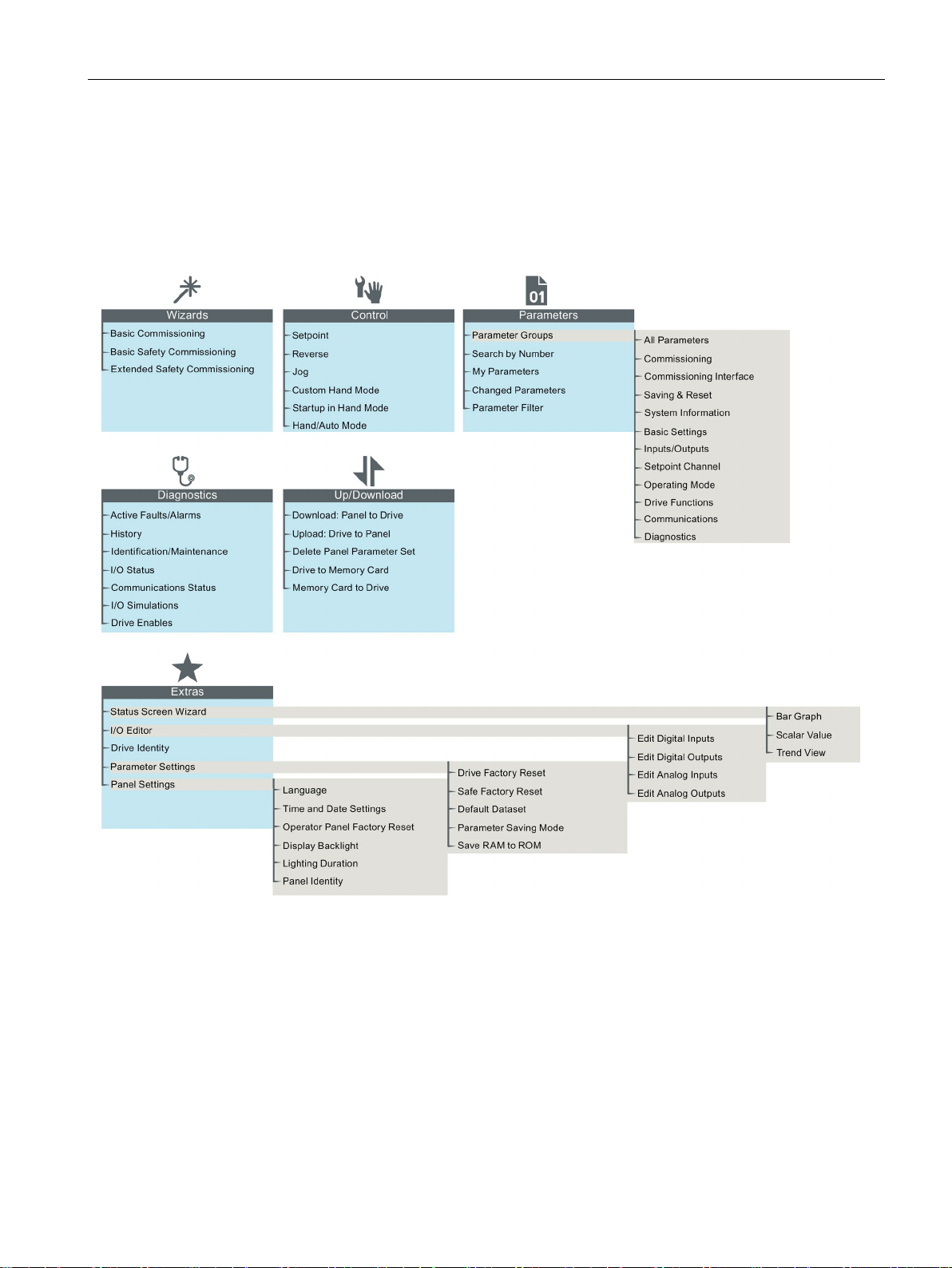
3.4
Menu structure
Overview
3.4 Menu structure
The Menu structure of the IOP-2 is shown in the figure below.
Figure 3-3 IOP-2 menu structure
Intelligent Operating Panel 2 (IOP-2)
Operating Instructions, 04/2017, FW V2.0, A5E39549448B AA
17

Overview
3.4 Menu structure
Intelligent Operating Panel 2 (IOP-2)
18 Operating Instructions, 04/2017, FW V2.0, A5E39549448B AA
4
4.1
Fitting the IOP-2
Fitting the IOP-2 to the Control Unit
Note
IOP-2 power supply
The IOP
of the converter through the RS232 interface. The IOP
derives its power through the USB connection.
-2 has no internal power supply and derives its power directly from the Control Unit
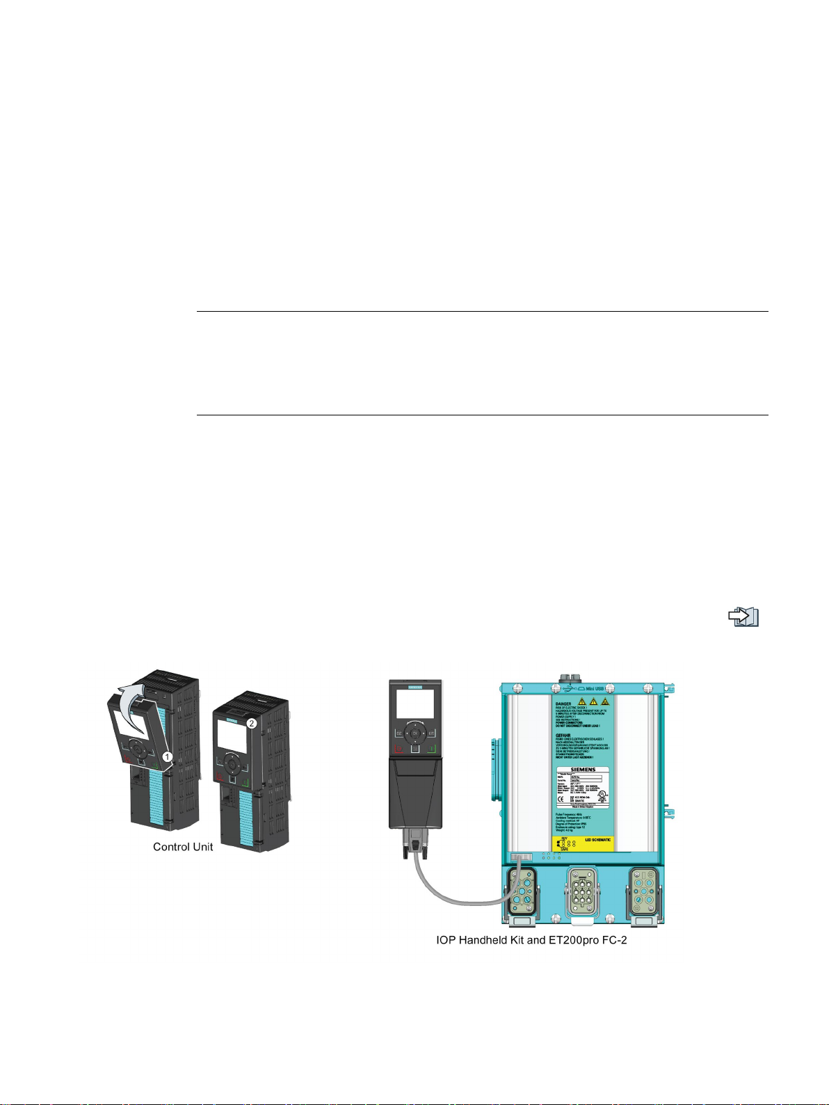
To fit the IOP-2 to the converter Control Unit the following procedure should be performed:
-2 can also be connected to a PC and
1. Place the bottom edge of the IOP-2 casing into the lower recess of the Control Unit
housing.
2. Push the IOP-2 forward until the top fastening clicks into place on the Control Unit
housing.
To use the IOP-2 with a decentralized drive, for example an ET200pro FC-2, an IOP-2
Handheld kit is required and an optical cable. The IOP-2 Handheld kit and optical cable are
fitted as shown in the following figure.
The order details of both the IOP-2 Handheld kit and the optical cable are given in the
Introduction (Page 11).
Figure 4-1 Fitting IOP-2 on CU and ET200pro FC-2
Intelligent Operating Panel 2 (IOP-2)
Operating Instructions, 04/2017, FW V2.0, A5E39549448B AA
19
Installation
4.2
Initial set-up
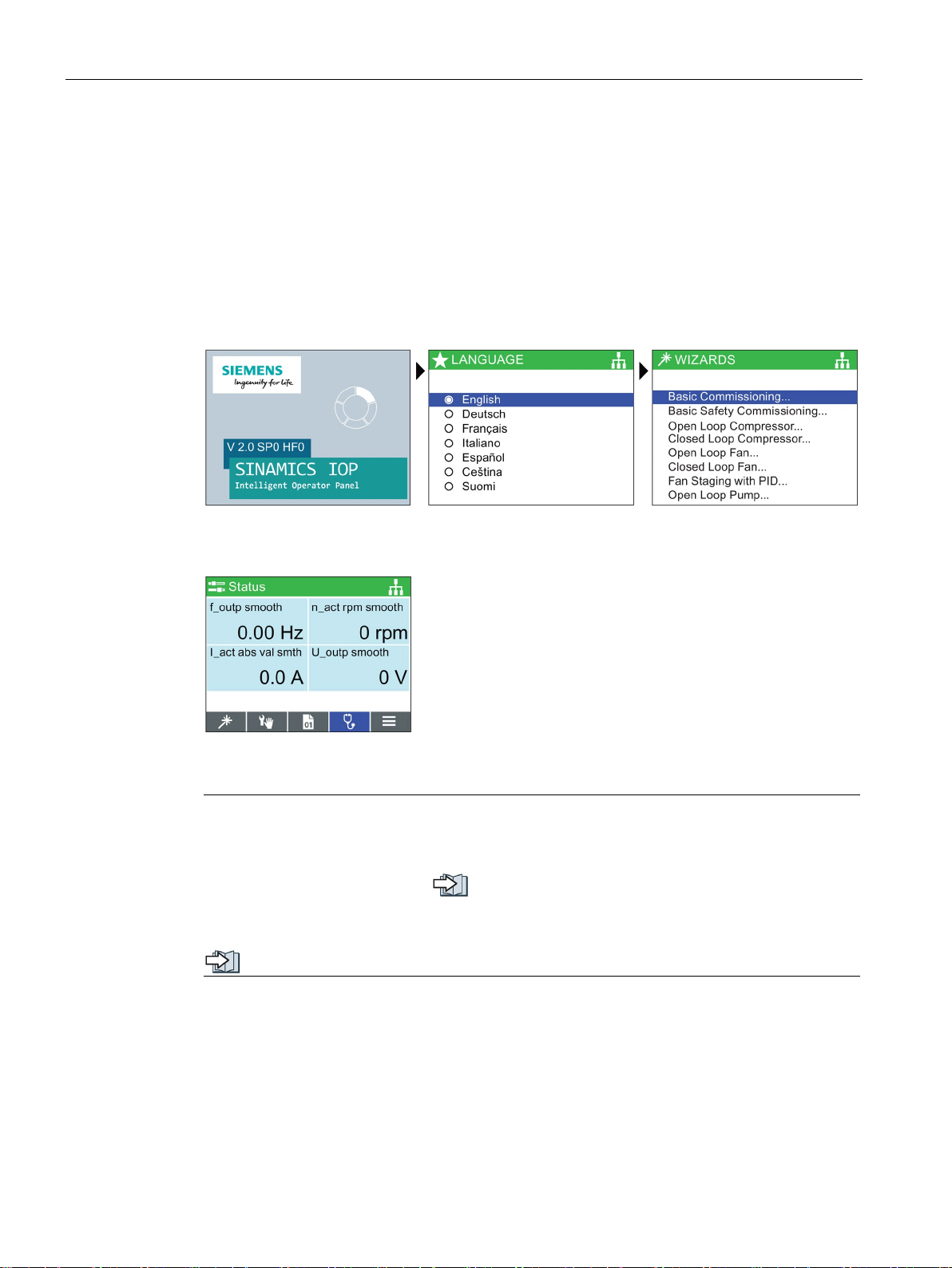
Initial set-up sequence
Splash screen is displayed
Select the required l
Select the required wizard or
press ESC
Status screen is displayed
Note
The IOP
wizards will depend on the type of Control Unit that is being used. For information on
Firmware upgrades, please see
The status s
values; these can be configured using the "Status Screen Wizard" in the "Extras" menu, see
4.2 Initial set-up
Once the IOP-2 is fitted and powered-up it will automatically detect the type of Control Unit
and Power Module to which it has been fitted. On first-time use, the IOP-2 automatically
displays the option to select the default language and allow the time and date to be set (if the
Control Unit to which the IOP-2 is fitted has a real-time clock). The procedure is outlined
below.
anguage
-2 is delivered with all available languages and wizards, although the number of
Firmware upgrade (Page 25).
creen can be reconfigured to show a number of different views and types of
Extras Menu (Page 51).
Intelligent Operating Panel 2 (IOP-2)
20 Operating Instructions, 04/2017, FW V2.0, A5E39549448B AA
Installation
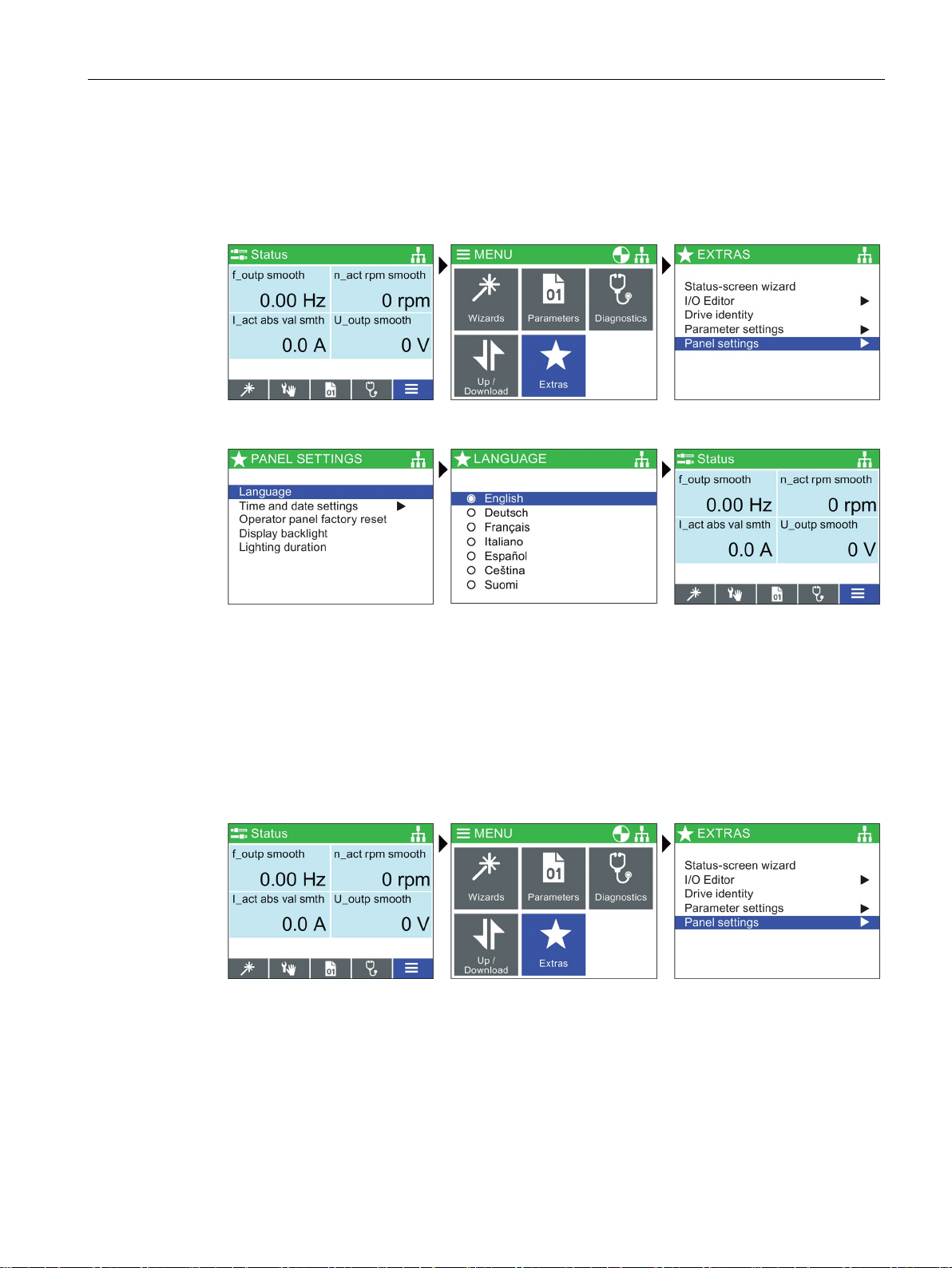
Language selection
Select Menu
Select Extras
Select Panel settings
Select language
Select required language
Press and hold down ESC for
Status Screen
Setting time and date
Select Menu
Select Extras
Select Panel settings
4.2 Initial set-up
The IOP-2 on first start-up will display the langauge screen for the user to select their
required language, should you wish to select you language manually, the following actions
should be performed:
All available languages are delivered with the IOP-2.
When the IOP-2 is first fitted to a Control Unit, which has a real-time clock, it will
automatically display the time and date screen. Should you wish to manually set the time on
the IOP-2, the following actions should be performed:
Intelligent Operating Panel 2 (IOP-2)
Operating Instructions, 04/2017, FW V2.0, A5E39549448B AA
21

Installation
Select Time and date
settings
Set the Time and date
settings
Set time and dat
Press and hold down ESC for
Status Screen
Lighting duration
Select Menu
Select Extras
Select Panel settings
4.2 Initial set-up
e
The settings for time are normally done on the Control Unit if it has a Real-time Clock (RTC).
If the Inverter has an RTC the IOP-2 will take its settings from the Control Unit.
To set the length of time that the display remains lit, the following actions should be
performed:
Intelligent Operating Panel 2 (IOP-2)
22 Operating Instructions, 04/2017, FW V2.0, A5E39549448B AA
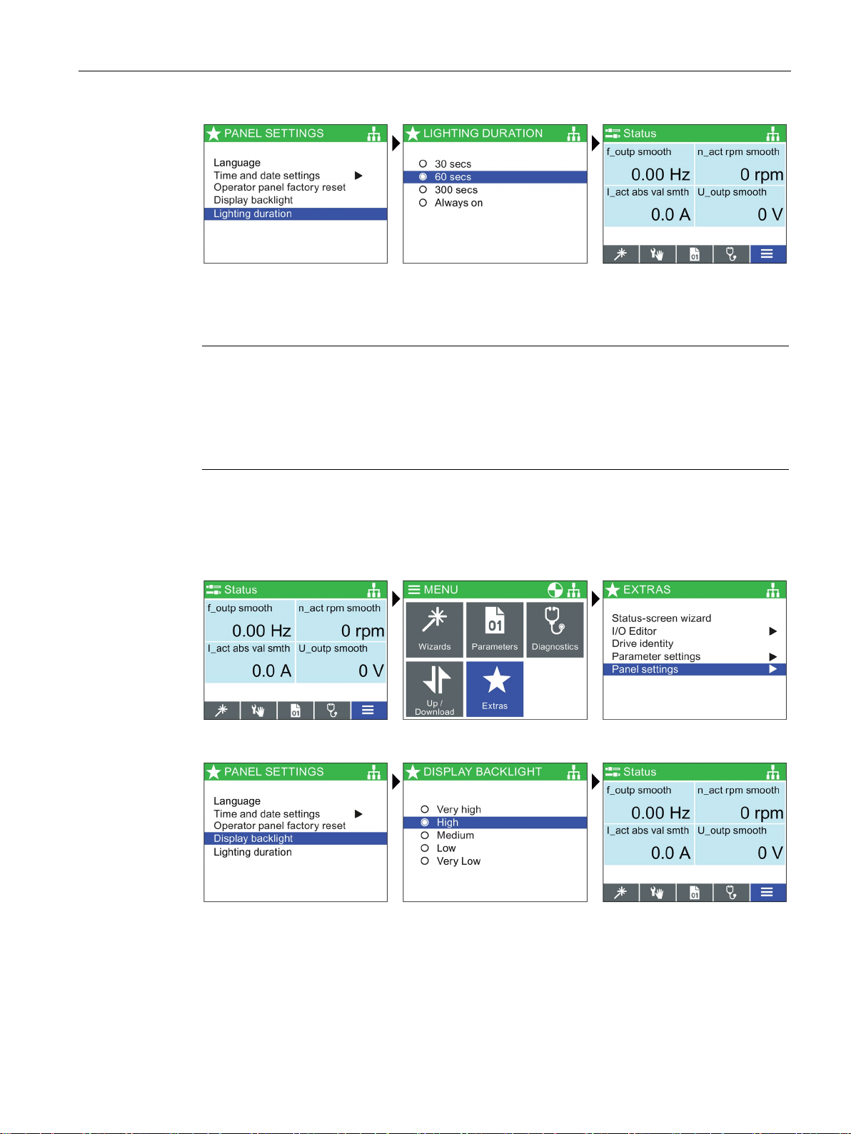
Installation
Select Lighting duration
Select Lighting duration time
Press and hold down ESC for
Status Screen
Note
Screen will flash when an active fault condition exists
When an active fault condition exists on the IOP-2, if no key has been pressed for more than
one minute then the screen will start to flash on and off. The screen will dim a few seconds
prior to the lighting duration time
been set to "Always on" the screen will not dim.
Display backlight
Select Menu
Select Extras
Select Panel settings
Select Display backlight
Select display backlight level
Press and hold down ESC for
Status Screen
4.2 Initial set-up
-out period. If the screen is set to never dim, that is, it has
To change the intensity of the backlight, the following actions should be performed:
The display backlight setting will be automatically changed to the "Low" setting after 60
seconds from the last key press to extend the life of the display. When any key is pressed
the backlight setting will automatically return to the user setting.
Intelligent Operating Panel 2 (IOP-2)
Operating Instructions, 04/2017, FW V2.0, A5E39549448B AA
23
 Loading...