

Page 1

Page 2

Page 3

Intelligent Operator Panel (IOP)
___________________
___________________
___________________
___________________
___________________
___________________
___________________
___________________
SINAMICS
Intelligent Operator Panel (IOP)
Operating Instructions
Edition 08/2015, Firmware IOP V1.6.1
08/2015, FW V1.6.1
A5E00110011B AF
Safety notes
1
Overview
2
Installation
3
Wizards
4
Control
5
Menu
6
Options
7
Technical data
8
Page 4

Siemens AG
Division Digital Factory
Postfach 48 48
90026 NÜRNBERG
GERMANY
Order number: (null)
Ⓟ
Copyright © Siemens AG 2015.
All rights reserved
Legal information
Warning notice system
DANGER
indicates that death or severe personal injury will result if proper precautions are not taken.
WARNING
indicates that death or severe personal injury may result if proper precautions are not taken.
CAUTION
indicates that minor personal injury can result if proper precautions are not taken.
NOTICE
indicates that property damage can result if proper precautions are not taken.
Qualified Personnel
personnel qualified
Proper use of Siemens products
WARNING
Siemens products may only be used for the applications described in the catalog and in the relevant technical
ntenance are required to ensure that the products operate safely and without any problems. The permissible
ambient conditions must be complied with. The information in the relevant documentation must be observed.
Trademarks
Disclaimer of Liability
This manual contains notices you have to observe in order to ensure your personal safety, as well as to prevent
damage to property. The notices referring to your personal safety are highlighted in the manual by a safety alert
symbol, notices referring only to property damage have no safety alert symbol. These notices shown below are
graded according to the degree of danger.
If more than one degree of danger is present, the warning notice representing the highest degree of danger will
be used. A notice warning of injury to persons with a safety alert symbol may also include a warning relating to
property damage.
The product/system described in this documentation may be operated only by
task in accordance with the relevant documentation, in particular its warning notices and safety instructions.
Qualified personnel are those who, based on their training and experience, are capable of identifying risks and
avoiding potential hazards when working with these products/systems.
Note the following:
documentation. If products and components from other manufacturers are used, these must be recommended
or approved by Siemens. Proper transport, storage, installation, assembly, commissioning, operation and
mai
All names identified by ® are registered trademarks of Siemens AG. The remaining trademarks in this publication
may be trademarks whose use by third parties for their own purposes could violate the rights of the owner.
We have reviewed the contents of this publication to ensure consistency with the hardware and software
described. Since variance cannot be precluded entirely, we cannot guarantee full consistency. However, the
information in this publication is reviewed regularly and any necessary corrections are included in subsequent
editions.
for the specific
07/2015 Subject to change
Page 5

Table of contents
1 Safety notes ............................................................................................................................................ 9
2 Overview............................................................................................................................................... 11
3 Installation ............................................................................................................................................ 17
4 Wizards ................................................................................................................................................ 25
5 Control .................................................................................................................................................. 45
6 Menu .................................................................................................................................................... 57
7 Options ............................................................................................................................................... 105
2.1 Introduction ............................................................................................................................. 11
2.2 Layout and functions ............................................................................................................... 12
2.3 Screen icons ........................................................................................................................... 15
2.4 Menu structure ........................................................................................................................ 16
3.1 Fitting the IOP ......................................................................................................................... 17
3.2 Initial Set-up ............................................................................................................................ 18
3.3 User definable labels for the Status screen ............................................................................ 22
3.4 Firmware and language upgrade ............................................................................................ 23
4.1 Example wizard ....................................................................................................................... 31
4.1.1 Basic commissioning with IOP ................................................................................................ 33
4.1.2 Wiring diagrams ...................................................................................................................... 36
5.1 Custom Hand mode ................................................................................................................ 49
5.2 Startup in Hand mode ............................................................................................................. 53
5.3 Hand/Auto disable ................................................................................................................... 54
6.1 Overview ................................................................................................................................. 57
6.2 Diagnostics ............................................................................................................................. 58
6.3 Parameters ............................................................................................................................. 62
6.4 Up/Download .......................................................................................................................... 68
6.5 Custom parameter sets........................................................................................................... 69
6.6 Extras ...................................................................................................................................... 73
6.7 I/O Editor ................................................................................................................................. 85
6.8 Write Protection ...................................................................................................................... 87
6.9 Know-how Protection .............................................................................................................. 89
7.1 Door mounting kit .................................................................................................................. 105
7.2 Hand-held device .................................................................................................................. 107
Intelligent Operator Panel (IOP)
Operating Instructions, 08/2015, FW V1.6.1, A5E00110011B AF
5
Page 6

Table of contents
8 Technical data ..................................................................................................................................... 113
Index ................................................................................................................................................... 115
Intelligent Operator Panel (IOP)
6 Operating Instructions, 08/2015, FW V1.6.1, A5E00110011B AF
Page 7

Changes in the manual
New Firmware Functions for V1.6.1
In Chapter
I/O Editor
Daylight Saving Time (DST)
information see the "Extra" section in this manual.
User definable labels
the user's own requirements.
Copying IOP parameter sets
saved onto an IOP to any number of other IOPs.
Copying "My Parameters" lists
saved on an IOP to any number of other IOPs
Note
Firmware version restrictions
The functions described in the table above require firmware version V4.7 SP3 to be installed
in the Control Unit, all other functionality described in this manual is independent of the
firmware installed on the Control
The I/O Editor allows the direct configuration of the Digital
Inputs, Digital Outputs, Analog Inputs and Analog Outputs.
The DST function allows the user to configured the Control
Unit's real-time clock's daylight saving settings. For more
The labels used on the status screen can be customised to
This explains how to copy an IOP parameter set that is
This explains how to copy the "My Parameters" list that is
I/O Editor (Page 85)
Extras (Page 73)
User definable labels for the Status
screen (Page 22)
Custom parameter sets (Page 69)
Figure Configuration file location
(Page 67)
Units.
Intelligent Operator Panel (IOP)
Operating Instructions, 08/2015, FW V1.6.1, A5E00110011B AF
7
Page 8

Safety notes
Intelligent Operator Panel (IOP)
8 Operating Instructions, 08/2015, FW V1.6.1, A5E00110011B AF
Page 9

1
Warnings and cautions
DANGER
Ensuring a safe and stable state
Note
•
•
During commissioning of the Inverter it is essential to ensure that the system is in a safe
and stable state, as some commissioning processes have the potential to start the motor.
Therefore it is important to secure any loads and ensure that should the motor start, no
potentially dangerous conditions exist.
The IOP can be fitted to and removed from the inverter while power is applied.
The IOP will set the USS PZD (P2012) length to 4 when connected to the inverter.
Intelligent Operator Panel (IOP)
Operating Instructions, 08/2015, FW V1.6.1, A5E00110011B AF
9
Page 10

Safety notes
Intelligent Operator Panel (IOP)
10 Operating Instructions, 08/2015, FW V1.6.1, A5E00110011B AF
Page 11

2
2.1
Introduction
Compatibility
Note
IOP functional support
•
•
– The selected functional group filtering of the parameters.
The Intelligent Operator Panel (IOP) has been designed to enhance the interface and
communications capabilities of SINAMICS Inverters.
The IOP connects to the Inverter through an RS232 interface. It has been designed to
automatically recognize the following devices from the SINAMICS range:
● SINAMICS G120 CU230P-2
● SINAMICS G120 CU240B-2
● SINAMICS G120 CU240E-2
● SINAMICS G120 CU250S-2
● SINAMICS G120C
● SINAMICS G120D-2 CU240D-2*
● SINAMICS G120D-2 CU250D-2*
● SINAMICS ET 200pro FC-2*
● SINAMICS G110D*
● SINAMICS G110M*
● SINAMICS S110 CU305*
*Denotes Control Units that require the IOP Hand-Held Kit to connect the IOP to the Control
Unit.
Hand-Held Kit order number: 6SL3255-0AA00-4HA0.
Optical cable order number: 3RK1922-2BP00 (not required for the SINAMICS S110 CU305)
For information on firmware and language upgrades, please see Firmware and language
upgrade (Page 23).
Drives with SINAMICS firmware prior to version 4.2 may not be fully supported by the
IOP.
The actual menu structure and functionality of the IOP will be influenced by the following
factors:
– The software version and type of Control Unit to which the IOP is fitted.
– The firmware and software version of the IOP.
Intelligent Operator Panel (IOP)
Operating Instructions, 08/2015, FW V1.6.1, A5E00110011B AF
11
Page 12
Overview
2.2
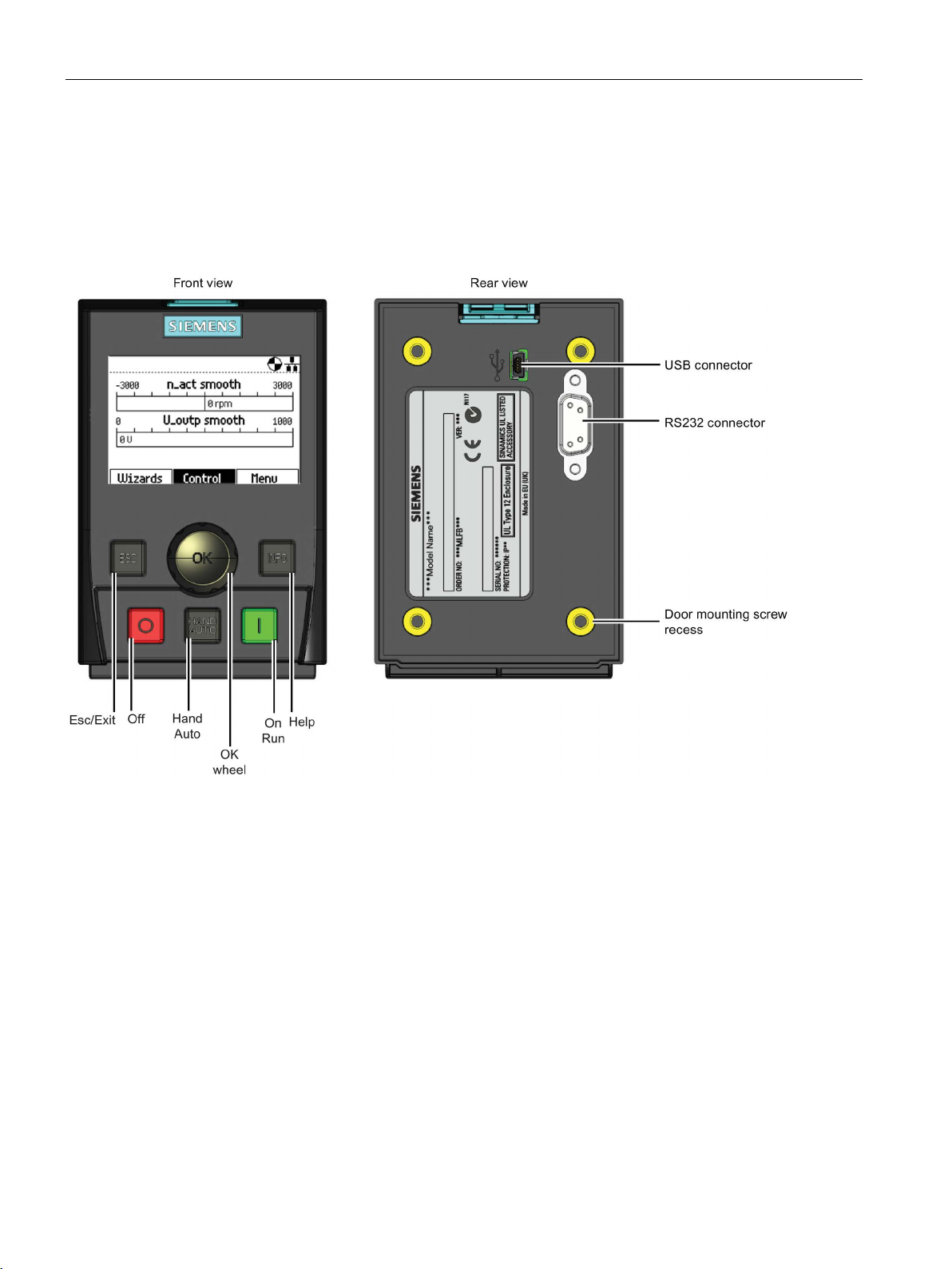
Layout and functions
Overview
2.2 Layout and functions
The physical layout of the IOP is shown below:
Figure 2-1 Layout of IOP
Intelligent Operator Panel (IOP)
12 Operating Instructions, 08/2015, FW V1.6.1, A5E00110011B AF
Page 13

Overview
Key
Function
When the Inverter is running in HAND mode, the motor stops when switched to AUTO.
When using the ESC key in the parameter editing mode, no data is saved unless the OK key is pressed first.
2.2 Layout and functions
The IOP is operated by using a push-wheel and five additional buttons. The specific
functions of the push-wheel and buttons are shown in the table below.
Table 2- 1 Function of the IOP controls
The push-wheel has the following functions:
• In a menu, turning the push-wheel changes the selection.
• When a selection is highlighted, pressing the push-wheel confirms the selection.
• When editing a parameter, turning the push-wheel changes the displayed value; clockwise increases the
value and anti-clockwise decreases the displayed value.
• When editing parameter or search values there is a choice to edit individual digits or an entire value.
With a long press of the push-wheel (>3 sec) it will toggle between the two different value editing modes.
The ON key has the following functions:
• In AUTO mode, the screens displays an information screen, stating that the command sources is AUTO
and can be changed by pressing the HAND/AUTO KEY.
• In HAND mode the Inverter is started - the Inverter status icon starts turning.
Notes:
For Control Units with firmware versions less than 4.0:
When running in AUTO mode, HAND mode cannot be selected unless the Inverter is stopped.
For Control Units with firmware versions 4.0 or greater:
When running in AUTO mode, HAND mode can be selected and the motor will continue to run at the last
selected setpoint speed.
The OFF key has the following functions:
• If pressed for longer than 3 seconds the Inverter will perform an OFF2; the motor will then coast down to
a standstill. Note: 2 presses of the OFF key within 3 seconds will also perform and OFF2.
• If pressed for less than 3 seconds the following actions will be performed:
– If in AUTO mode the screen will display an information screen stating that the command sources is
AUTO and can be changed using the HAND/AUTO key. The Inverter will not be stopped.
– If in HAND mode the Inverter will perform an OFF1; the motor will come to a standstill in the ramp-
down time set in parameter P1121.
The ESC key has the following functions:
• If pressed for less than 3 seconds the IOP returns to the previous screen or if a value has been edited,
the new value is not saved.
• If pressed longer than 3 seconds the IOP returns to the status screen.
Intelligent Operator Panel (IOP)
Operating Instructions, 08/2015, FW V1.6.1, A5E00110011B AF
The INFO key has the following functions:
• Displays additional information for the currently selected item.
• Pressing the INFO key again will display the previous screen.
• Pressing the INFO key during power-up of the IOP will place the IOP in DEMO mode. To exit DEMO
mode, power-cycle the IOP.
The HAND/AUTO key switches the command source between HAND and AUTO mode.
• HAND sets the command source to the IOP.
• AUTO sets the command source to an external source, for example, fieldbus.
13
Page 14

Overview
Changes in functionality of the IOP keys
DEMO mode
Locking and unlocking the keypad
ESC
INFO
ESC
INFO
2.2 Layout and functions
The functionality of the individual controls of the IOP is changed when the following functions
are activated, the user should be aware of these changes of functions to ensure that the IOP
operates in the intended manner.
● Custom Hand mode Custom Hand mode (Page 49)
● Startup in Hand mode Startup in Hand mode (Page 53)
● Hand/Auto disable Hand/Auto disable (Page 54)
To enter the DEMO mode it is necessary to do a long press of the ESC key or INFO key
during the power-up cycle. The IOP must be power cycled again to exit the DEMO mode.
DEMO mode allows the IOP to be used for demonstration purposes without affecting the
Inverter to which it is connected. Menus can be navigated and functions selected, but all
communications with the Inverter are blocked to ensure that the Inverter does not react to
any commands issued from the IOP.
The keypad can only be locked once the power-up cycle has been completed. If the keys are
actived before the power-up cycle is completed, the IOP will enter the DEMO mode.
To lock the IOP keypad press
unlock the keypad press
and
and
simultaneously for 3 seconds or more. To
simultaneously for 3 seconds or more.
Intelligent Operator Panel (IOP)
14 Operating Instructions, 08/2015, FW V1.6.1, A5E00110011B AF
Page 15

Overview
2.3
Screen icons
Overview
Function
Status
Icon
Remarks
to RAM will be lost.
Hand-held kit is used.
2.3 Screen icons
The IOP displays a number of icons at the top right-hand edge of the display to indicate
various states or current conditions of the Inverter. These icons are explained in the table
below.
Table 2- 2 Screen icons
Command source Auto
JOG
Hand
Inverter status Ready
Running
Fault pending Fault
Alarm pending Alarm
Saving to RAM Active
PID autotuning Active
Hibernation mode Active
Write Protection Active
Know How Protection Active
ESM Active
Displayed when the JOG function is active.
Icon rotates when the motor is running
Indicates that all recent changes of parameters
have been saved in RAM only. Should power to
the IOP be lost, then all recent changes saved
Parameters cannot be modified.
Parameters cannot be viewed or modified.
Essential Services Mode
Intelligent Operator Panel (IOP)
Operating Instructions, 08/2015, FW V1.6.1, A5E00110011B AF
Battery condition Charged
The battery status is only shown when the IOP
15
Page 16
Overview
2.4
Menu structure
Overview
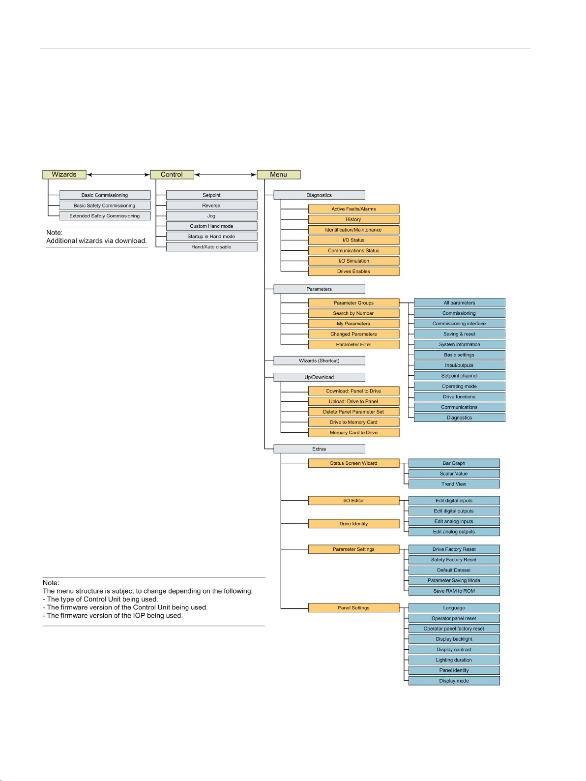
2.4 Menu structure
The IOP is a menu-driven device and has the following menu structure:
Figure 2-2 IOP menu structure
Intelligent Operator Panel (IOP)
16 Operating Instructions, 08/2015, FW V1.6.1, A5E00110011B AF
Page 17
3
3.1
Fitting the IOP
Fitting the IOP to the Control Unit
Note
IOP power supply
The IOP has no internal power supply and derives its power directly from the Control Unit of
the Inverter through the RS232 interface. The IOP can also be connected to a PC and
derives its power through the USB connection.
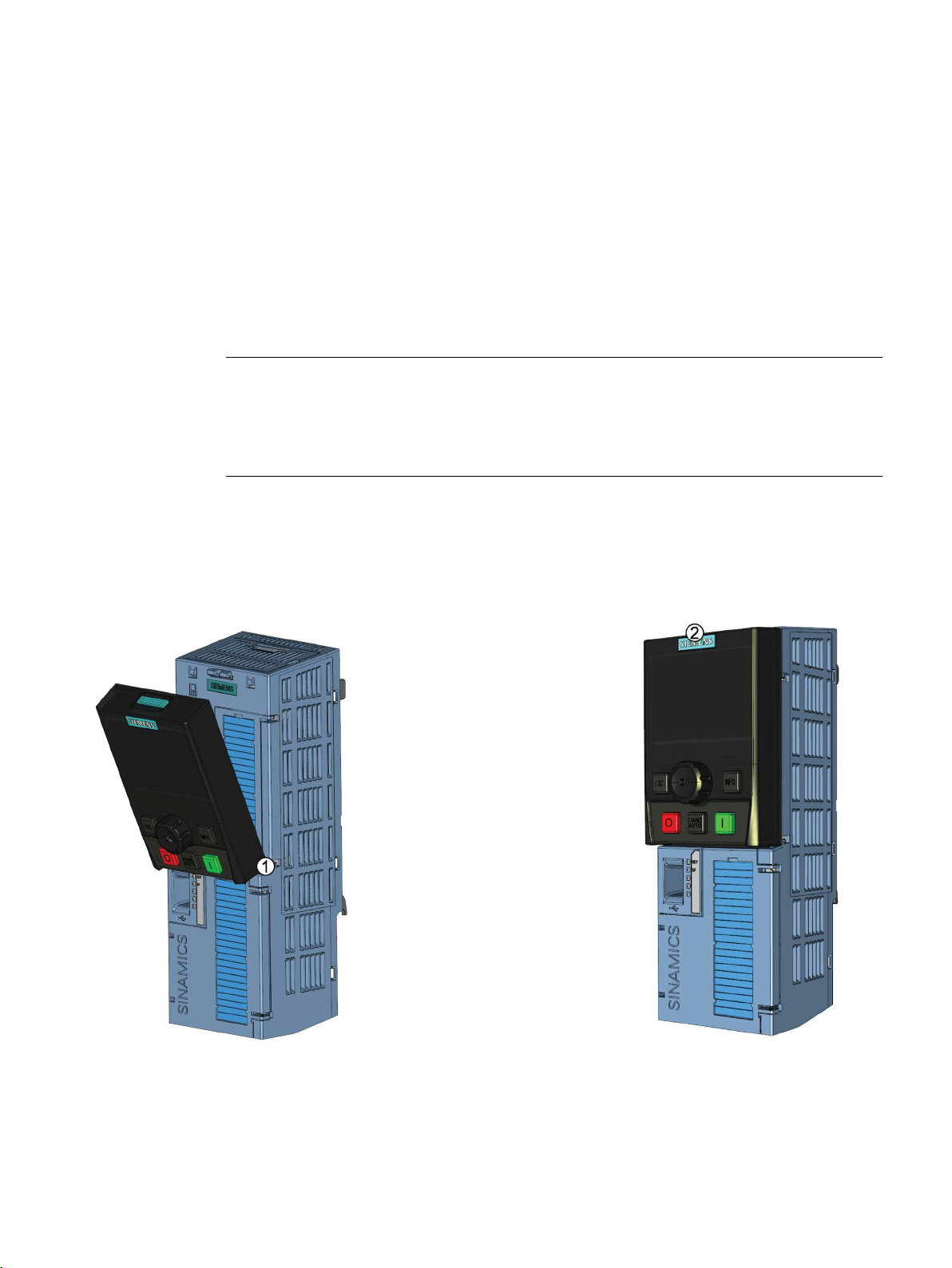
To fit the IOP to the Inverter Control Unit the following procedure should be performed:
1. Place the bottom edge of the IOP casing into the lower recess of the Control Unit
housing.
2. Push the IOP forward until the top fastening clicks into place on the Control Unit housing.
Figure 3-1 Fitting the IOP to the Control Unit
Intelligent Operator Panel (IOP)
Operating Instructions, 08/2015, FW V1.6.1, A5E00110011B AF
17
Page 18
Installation
3.2
Initial Set-up
Initial set-up sequence
After the initial start
will then display details of the type of Control Unit and Power
module, inclu
After the Ide
guage selection screen will be displayed.
Once the language is selected
played.
Note:
The IOP is delivered with only the Basic Commissioning wi
ards. All other wizards can be downloaded using the IOP u
dater tool. For futher information, please see
language upgrade
3.2 Initial Set-up
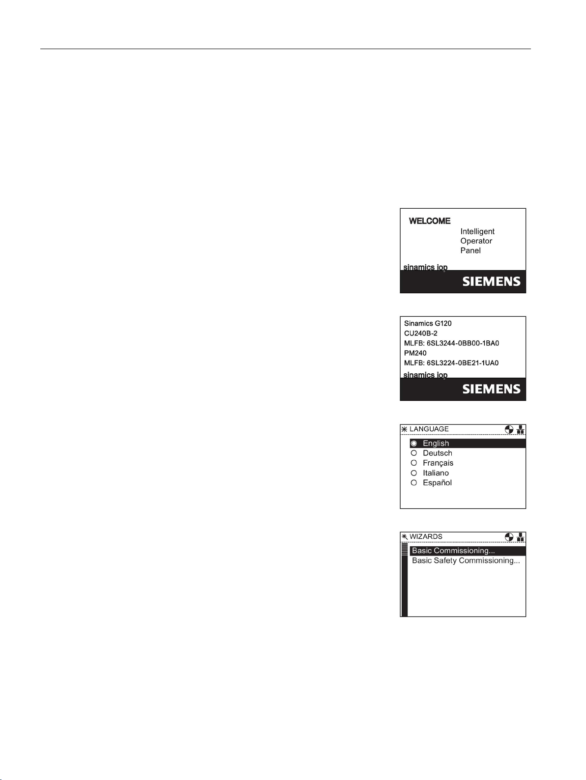
Once the IOP is fitted and powered-up it will automatically detect the type of Control Unit and
Power Module to which it has been fitted. On first-time use, the IOP automatically displays
the option to select the default language and allow the time and date to be set (if the Control
Unit to which the IOP is fitted has a real-time clock).
-up screen has been displayed, the IOP
ding the orders numbers.
ntification screen has been displayed the Lan-
(Page 23).
Intelligent Operator Panel (IOP)
18 Operating Instructions, 08/2015, FW V1.6.1, A5E00110011B AF
- the Wizard menu is dis-
zp-
Firmware and
Page 19
Installation
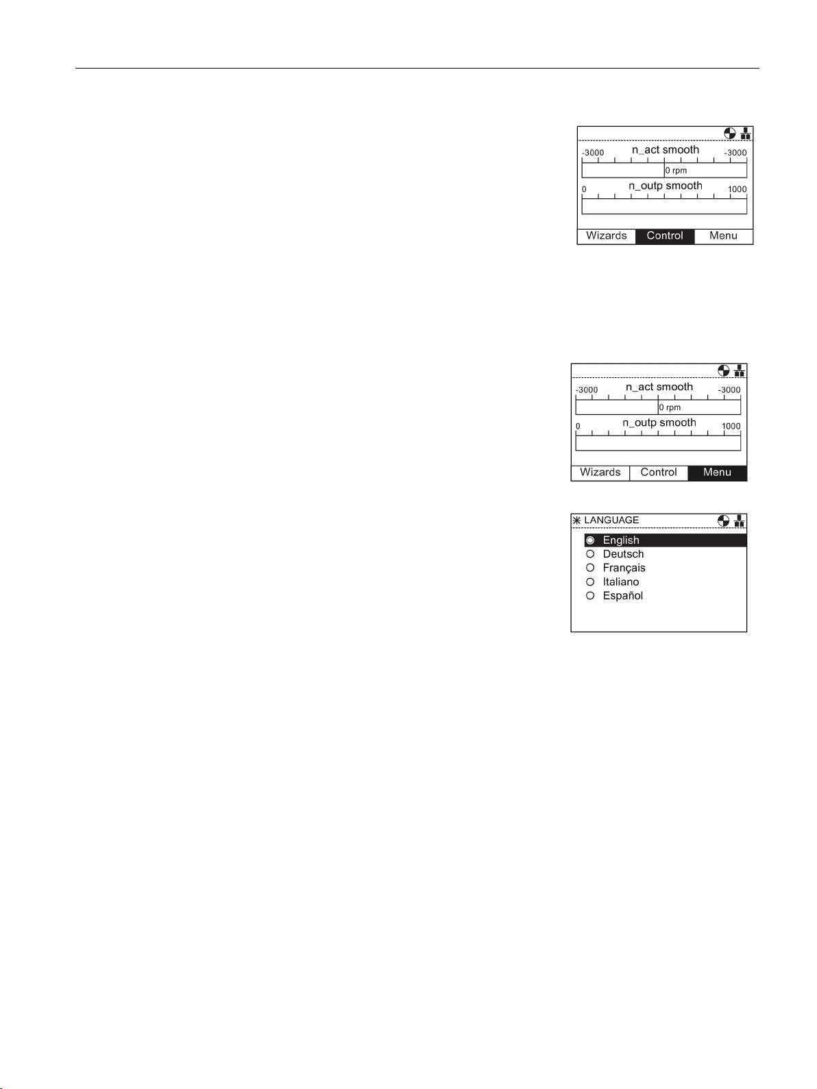
If the Wizard menu is not required, then press Esc to return to
the normal status screen.
The status screen can be reconfigured to show a number of
different views and types of values; these can be configured
using the "Status Screen Wizard
Extras
Extras
Language selection
1.
Wheel
Menu
2.
Wheel
3.
Menu
4.
Wheel
Extras
5.
Wheel
6.
Extras
7.
Wheel
Panel Settings
8.
Wheel
9.
Wheel
10.
Wheel
11.
12.
Wheel
13.
Wheel
14.
15.
Extras
16.
Esc
Status
3.2 Initial Set-up
To select the language that the IOP should display, the following actions should be
performed:
" in the "
" menu, see
(Page 73).
Rotate the
Press the
The "
Rotate the
Press the
The "
Rotate the
Press the
Rotate the
Press the
" screen is displayed.
to select "
".
to confirm selection.
to select "
".
to confirm selection.
" screen is displayed.
to select "
to confirm selection.
to select the required language.
to confirm selection.
"
The "Language" screen is displayed.
Rotate the
Press the
to select the language.
to confirm selection.
The selected language will now be used by the IOP.
The IOP will return to the "
Press "
"
" for more than 3 seconds to return to the
" screen.
" menu.
Additonal languages are available for the IOP. For further information, please see Firmware
and language upgrade (Page 23).
Intelligent Operator Panel (IOP)
Operating Instructions, 08/2015, FW V1.6.1, A5E00110011B AF
19
Page 20
Installation
Setting time and date
1.
Time and Date
2.
Wheel
3.
Wheel
4.
Wheel
5.
Wheel
6.
7.
Extras
8.
Esc
Status
Lighting duration
1.
Wheel
Menu
2.
Wheel
3.
Menu
4.
Wheel
Extras
5.
Wheel
6.
Extras
7.
Wheel
Panel Settings
8.
Wheel
9.
Wheel
Lighting duration
10.
Wheel
11.
Lighting duration
12.
Wheel
13.
Wheel
14.
Extras
15.
Esc
Status
3.2 Initial Set-up
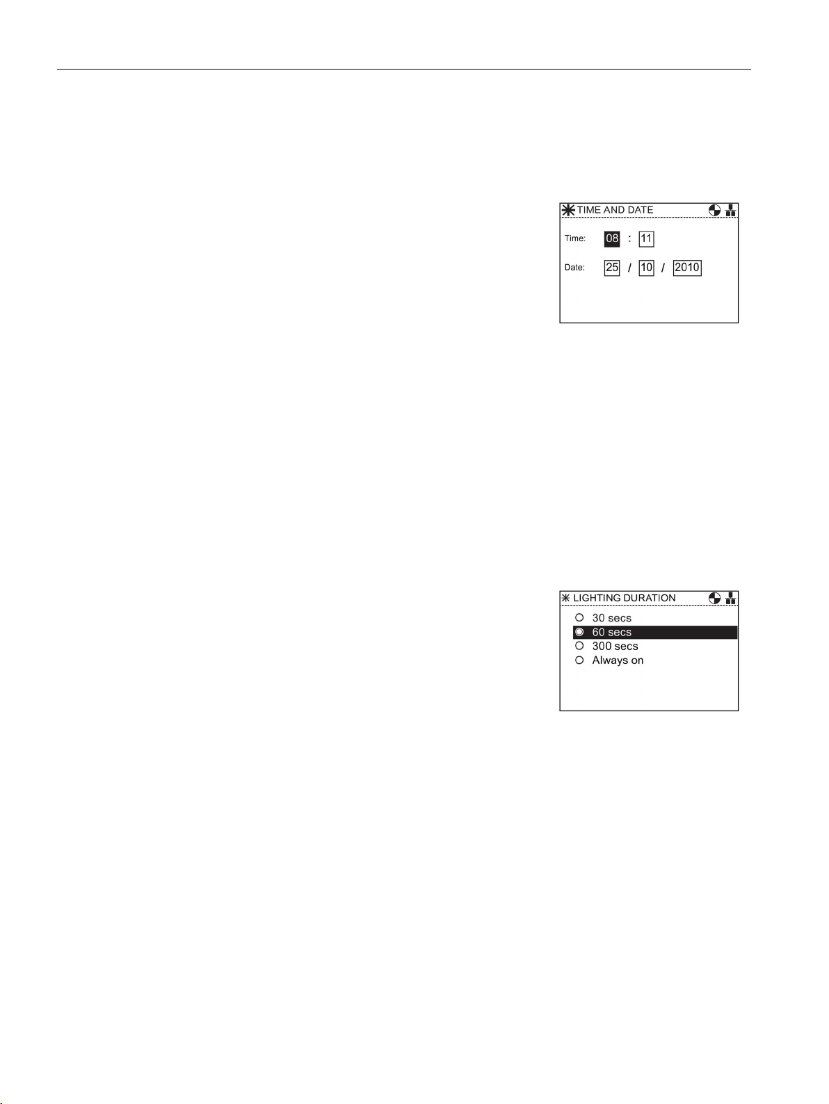
When the IOP is first fitted to a Control Unit, which has a real-time clock, it will automatically
display the time and date screen, the following actions should be performed:
The "
Rotate the
Press the
next field.
Rotate the
Press the
field.
Continue the process for the date fields.
When the last field of the date is completed, the screen
will return to the "
Press "
"
" for more than 3 seconds to return to the
" screen.
The settings for time are normally done on the Control Unit if it has a Real-time Clock (RTC).
If the Inverter has an RTC the IOP will take its settings from the Control Unit.
" screen is displayed.
to change the value.
to confirm the value and move to the
to change the value.
to confirm value and move to the next
" menu.
To set the length of time that the display remains lit, the following actions should be
performed:
Rotate the
Press the
The "
Rotate the
Press the
The "
Rotate the
Press the
Rotate the
Press the
The "
Rotate the
Press the
The display returns to the "
Press "
"
" screen.
Intelligent Operator Panel (IOP)
20 Operating Instructions, 08/2015, FW V1.6.1, A5E00110011B AF
to select "
".
to confirm selection.
" screen is displayed.
to select "
".
to confirm selection.
" screen is displayed.
to select "
"
to confirm selection.
to selected "
".
to confirm selection.
" screen is displayed.
to select the required lighting duration.
to confirm selection.
" menu.
" for more than 3 seconds to return to the
Page 21
Installation
Display contrast
1.
Wheel
Menu
2.
Wheel
3.
Menu
4.
Wheel
Extras
5.
Wheel
6.
Extras
7.
Wheel
Panel Settings
8.
Wheel
9.
Wheel
10.
Wheel
11.
Display contrast
12.
Wheel
13.
Wheel
14.
Extras
15.
Esc
Status
Display backlight
1.
Wheel
Menu
2.
Wheel
3.
Menu
4.
Wheel
Extras
5.
Wheel
6.
Extras
7.
Wheel
Panel Settings
8.
Wheel
9.
Wheel
Display backlight
10.
Wheel
11.
Display backlight
12.
Wheel
13.
Wheel
14.
Extras
15.
Esc
Status
3.2 Initial Set-up
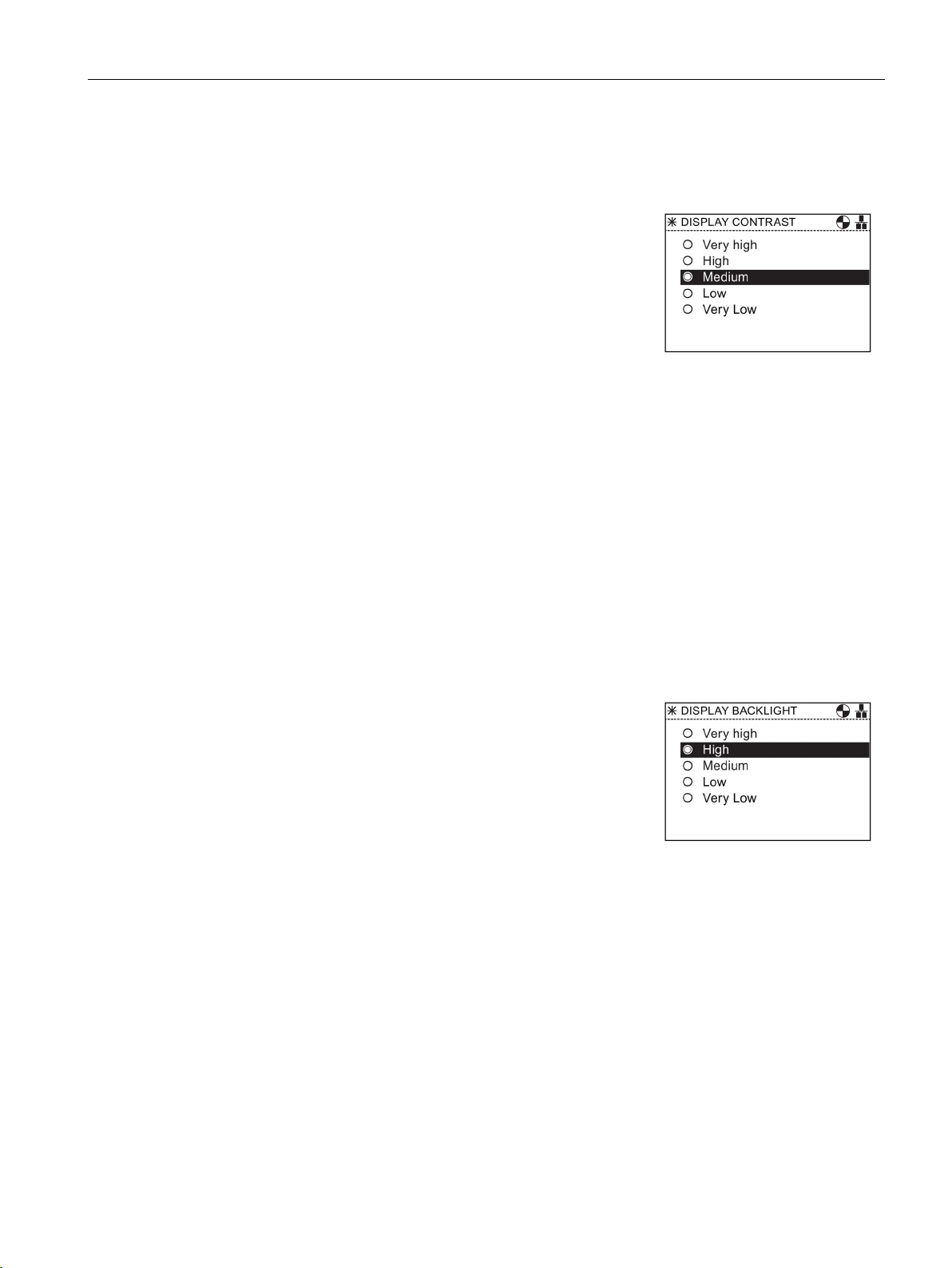
To set the contrast level of the IOP, the following actions should be performed:
Rotate the
Press the
The "
Rotate the
Press the
The "
Rotate the
Press the
Rotate the
Press the
The "
Rotate the
Press the
The display returns to the "
Press "
"
" screen.
to select "
".
to confirm selection.
" screen is displayed.
to select "
".
to confirm selection.
" screen is displayed.
to select "
"
to confirm selection.
to selected "Display contrast".
to confirm selection.
" screen is displayed.
to select the required contrast setting.
to confirm selection.
" menu.
" for more than 3 seconds to return to the
Intelligent Operator Panel (IOP)
Operating Instructions, 08/2015, FW V1.6.1, A5E00110011B AF
To change the intensity of the backlight, the following actions should be performed:
Rotate the
Press the
The "
Rotate the
Press the
The "
Rotate the
Press the
Rotate the
Press the
The "
Rotate the
to select "
".
to confirm selection.
" screen is displayed.
to select "
".
to confirm selection.
" screen is displayed.
to select "
to confirm selection.
to selected "
to confirm selection.
" screen is displayed.
to select the required brightness
"
".
setting.
Press the
The display returns to the "
Press "
"
" screen.
to confirm selection.
" menu.
" for more than 3 seconds to return to the
21
Page 22

Installation
Display mode
1.
Wheel
Menu
2.
Wheel
3.
Menu
4.
Wheel
Extras
5.
Wheel
6.
Extras
7.
Wheel
Panel Settings
8.
Wheel
9.
Wheel
Display mode
10.
Wheel
11.
Display mode
12.
Wheel
13.
Wheel
14.
Extras
15.
Esc
Status
3.3
User definable labels for the Status screen
User definable labels
3.3 User definable labels for the Status screen
The display backlight setting will be automatically changed to the "Low" setting after 60
seconds from the last key press to extend the life of the display. When any key is pressed
the backlight setting will automatically return to the user setting.
To change the display mode, the following actions should be performed:
Rotate the
Press the
The "
Rotate the
Press the
The "
Rotate the
Press the
Rotate the
Press the
The "
Rotate the
– "Normal" displays white text on a black background.
– "Inverse" displays black text on a white background.
Press the
The display returns to the "
Press "
"
" screen.
to select "
to confirm selection.
" screen is displayed.
to select "
to confirm selection.
" screen is displayed.
to select "
to confirm selection.
to selected "
to confirm selection.
" screen is displayed.
to select the required setting.
to confirm selection.
" for more than 3 seconds to return to the
".
".
"
".
" menu.
Intelligent Operator Panel (IOP)
22 Operating Instructions, 08/2015, FW V1.6.1, A5E00110011B AF
User defined labels allow the user to customize the labels that appear on the status screen
of the IOP.
There are a maximum of four labels that can be defined and they are located on the IOP in
the "cps" folder. The IOP must be connected to the PC via the USB connection and in "Mass
Storage" mode to access the files on the IOP.The files are basic text files and can be opened
with any basic text editor. The default label names are "default", when the labels have the
"default" text, the IOP will ignore the labels. There are the following restrictions when
creating your own labels:
● A maximum of 20 characters for each label name.
● The characters that can be used conform to the normal windows file naming conventions.
Page 23

Installation
3.4
Firmware and language upgrade
Overview
Note
English language is mandatory
The English language file is essential to the correct functioning of the IOP and therefore
cannot be deleted. All other available languages can be downloaded to the IOP or deleted as
necessary.
3.4 Firmware and language upgrade
● The number of labels are restriction depending on the type of status screen view that is
selected in the "Status screen wizard". see Extras (Page 73).
The four files are named:
● BotLeft.txt
● BotRight.txt
● TopLeft.txt
● TopRight.txt
The file names relate to the area of the status where they will appear.
Simply selected the file you wish to use as a label; open it with a text editor, change the
name and then save it back to the same location in the IOP file system. If the file name itself
is change the IOP will not recognize the label.
An example of the status screen with new label names (using the
files) is shown in the figure below.
Figure 3-2 User definable labels example
The IOP Updater tool allows the user to download:
● Additional language packs
● Firmware updates
BotLeft.txt
and
TopLeft.txt
● Additional wizards
● Application wizards
The IOP Udater tool contains the necessary drivers to allow the IOP to be connected to the
USB port of your PC with a mini USB cable.
Intelligent Operator Panel (IOP)
Operating Instructions, 08/2015, FW V1.6.1, A5E00110011B AF
23
Page 24

Installation
3.4 Firmware and language upgrade
Figure 3-3 IOP Updater
The IOP Updater software, additional wizards, firmware files and languages files can be
downloaded from the Siemens Service and Support website at the following link:
IOP Updater download (http://support.automation.siemens.com/WW/view/en/67273266)
The website contains getting started files which explain the installation and use of the IOP
Updater software.
Intelligent Operator Panel (IOP)
24 Operating Instructions, 08/2015, FW V1.6.1, A5E00110011B AF
Page 25

4
Overview
WARNING
Safe and stable state of the Inverter
CAUTION
Default datasets
Note
Default wizard and downloading
The IOP is delivered with only the Basic Commissioning Wizard installed. If the CU has
safety functions, the Basic Safety Commissioning Wizard will also be available.
All other wizard can be downloa
upgrade
Wizards
The IOP wizards are question-driven macros that assist the user to set-up various functions
and applications of the Inverter.
During commissioning of the Inverter it is essential to ensure that the system is in a safe
and stable state, as some commissioning processes have the potential to start the motor.
Therefore it is important to secure any loads and ensure that should the motor start, no
potentially dangerous conditions exist.
The wizards use the default Drive datasets (DDS0 and CDS0), if the default datasets are
changed to the other datasets, the wizards may not function correctly.
ded using the IOP updater tool, see Firmware and language
(Page 23)
There are several wizards (available via download) which allow the user to set-up various
functions and commission the Inverter. An example of the type of wizards are given below:
● Basic commissioning
● Open Loop Compressor
● Fixed Closed Loop Compressor
● Open Loop Fan
● Fixed Closed Loop Fan
● Open Loop Pump
Intelligent Operator Panel (IOP)
Operating Instructions, 08/2015, FW V1.6.1, A5E00110011B AF
● Fixed Closed Loop Pump
25
Page 26

Wizards
Note
Wizards
The actual menu structure and the functionality of the IOP will be influenced by the following
facto
•
•
•
SINAMICS ET200S (Pro) and SINAMICS G120D Inverters
The Roller conveyor wizard is the only application wizard available for SINAMICS ET 200pro
and SINAMICS G120D Inverters.
Accessing the IOP wizards
Prerequisites
Note
Factory reset
A factory reset
reset option is accepted.
● Boost
● PID Wizard
● Roller Conveyor
● Basic Safety Commissioning
● Extended Safety Commissioning
The relevant wiring diagrams, if required, are contained in the "Wiring diagrams" section in
this chapter.
rs:
The software version and type of Control Unit to which the IOP has been fitted.
The firmware and software version of the IOP.
The Roller conveyor wizard requires a fieldbus compatible Control Unit
(PROFIBUS/PROFINET).
Wizards are accessed from the wizards menu, at the bottom-left of the Status screen as
shown in the figure below.
Figure 4-1 Status screen with Wizard menu highlighted
Intelligent Operator Panel (IOP)
26 Operating Instructions, 08/2015, FW V1.6.1, A5E00110011B AF
option is offered by each wizard. It is highly recommended that the factory
Page 27

Wizards
Information requested by the wizards
Motor data
Sensor data
The user must ensure that all the following actions have been completed prior to using the
IOP application wizards:
● All necessary equipment is available and installed correctly, according to the relevant
wiring diagram for the specific application wizard.
● All wiring of the Inverter, motor and any other devices used within the application has
been completed in accordance with the wiring diagrams included in the appropriate
section of this manual.
● All components of the system have been tested to ensure their correct and safe
installation.
Since the IOP wizards will request detailed technical information during the setting-up
process, it is important to have this information available. This information can be obtained
from the following sources:
●
- this data is obtained from the motor rating plate. At the motor data stage of
the Basic Commissioning wizard, the individual data elements can be entered from the
data on rating label of the motor, or the motor code can be entered/selected. See figure
below.
●
- details of the types of sensors that may be used with the Inverter, such as
temperature sensors and pressure sensors. The required information is normally found
on the rating label of the sensor.
Figure 4-2 Typical motor rating label for input of motor data or motor code
Intelligent Operator Panel (IOP)
Operating Instructions, 08/2015, FW V1.6.1, A5E00110011B AF
27
Page 28

Wizards
Basic Commissioning
Open Loop Compressor
Fixed Closed Loop Compressor
Open Loop Fan
Fixed Closed Loop Fan
The basic commissioning of the Inverter and motor comprises a number of processes. The
processes are as follows:
● Basic commissioning
● Application class and control mode
● Calculation of motor and control data
The wizard will guide the user through the basic commissioning process by presenting a
number of screens where the user can choose the necessary options and values to
commission the Inverter and motor. At the conclusion of the basic commissioning process,
the data can be saved to the Inverters memory.
The Inverter is used to control the output pressure of a compressor to ensure that it adapts
to the varying volume of gas that is required to be compressed.
Compressing the gas involves reducing the volume and increasing the pressure within the
container to compress the gas.
The setpoint is controlled by the analog inputs.
A constant pressure is required to be maintained within a system utilizing the minimum use
of energy.
The pressure in the system is monitored using the PID controller and if the pressure remains
constant then the Inverter will run the system at the minimum frequency to maintain the
pressure.
The setpoints are controlled by analog input 0.
The feedback from the system are received from the pressure sensor utilizing analog input 1.
This feedback is then used by the Inverter to react to changes in the system pressure.
The on/off and reset commands are controlled using digital inputs 0 and 1 respectively.
The general monitoring of the condition of the Inverter is achieved using digital outputs 0, 1
and 2 for drive failure, drive ready and drive running respectively.
This is a basic fan application where the fan is under the control of the Inverter.
The purpose of the closed-loop controlled fan application is to maintain a constant airflow
within a ventilation system, utilizing as little energy as possible.
A specific airflow and pressure for the fan system is set within the Inverter and these values
are directly monitored using the PID controller. Depending on a decrease or increase in
pressure readings, the Inverter will increase or decrease the speed of the fan accordingly.
Intelligent Operator Panel (IOP)
28 Operating Instructions, 08/2015, FW V1.6.1, A5E00110011B AF
Page 29

Wizards
Open Loop Pump
Fixed Closed Loop Pump
Boost
PID Wizard
Roller conveyor
The purpose of this application is to maintain a constant level of fluid in a pumping system
and reacting to maintain the pre-determined level even if fluid is being drawn from the
system.
The analog input is used to set the frequency setpoint.
The closed-loop application allows for the fluid in a tank to be directly monitored using the
PID control function.
At low output frequencies, the V/f characteristics give only a low output voltage. This means
that the output voltage can be too low in order to:
● Implement the magnetization of an induction motor
● to hold the load
● to equalize losses in the system
● to provide a breakaway, acceleration or braking torque.
The output voltage can be increased (boosted) in the Inverter using the boost function.
The Boost settings wizard guide the user through the correct setting of the boost function.
Fixed Closed Loop control is widely used in industrial applications to control a wide variety of
processes. A simple closed-loop control uses a feedback signal from the process (such as,
temperature, pressure and speed) and a desired value or setpoint. The control system
compares the two values and derives an error signal. The error signal is used to control the
Inverter and motor to reduce the error.
The error signal processing can be very complex because of the delays in the system. The
error signal is processed using a Proportional and Integral differential (PID) controller whose
parameters can be adjusted to optimize the performance and stability of the system.
The PID controller wizard guide the user through the PID setting-up process.
This wizard can be used for the typical material handling applications, such as conveyor
belts, roller conveyors and turn-tables.
The sensors are directly connected to the Inverter to allow their individual status to be sent to
the controlling PLC.
Intelligent Operator Panel (IOP)
Operating Instructions, 08/2015, FW V1.6.1, A5E00110011B AF
29
Page 30

Wizards
Safety Commissioning
Fan staging with PID
This wizard is designed to allow the user to commission the Inverters with safety-integrated
functions. The user is guided through the necessary steps to commission the various safetyintegrated functions available, depending upon the type of Control Unit to be used with the
user application. The wizard will only display the functions that are available for their specific
Control Unit; if no safety functions are available, the wizard will not be displayed in the
wizard menu structure.
The are two levels of safety commissioning wizards and these are as follows:
● Basic Safety Commissioning - allows the configuration of the safety digital inputs and
signals for the following safety functions:
– Safe Torque Off (STO)
– ProfiSafe
● Extended Safety Commissioning - allows the configuration of the safety digital inputs and
signals for the following safety functions:
– Safe Stop 1 (SS1)
– Safe Stop 2 (SS2)
Each of these wizards can be used to configure inputs and signals for the users specific
application requirements.
this application is used to run several fans in parallel depending on the actual airflow
requirement.
One fan is under direct control and monitoring of the Inverter, the other fans are started and
stopped as required, but no feedback from the other fans is required. The monitoring is
performed by the use of pressure sensors utilizing the PID controller.
The analog inputs are used for setting the setpoint and receiving the feedback from the
various sensors, to which the PID control will react. The digital outputs are used to control
the fans.
Each fan, when started is ran at the minimum frequency; this is done to achieve a uniformed
increase in pressure/airflow without causing a surge in pressure within the system.
Since all fans have the ability to be started and stopped by the Inverter, it is possible to use
the fans in a different number of sequences to ensure that no one fan is working
permanently and the workload is distributed in a balanced manner.
– Safe Operating Stop (SOS)
– Safe Low Speed (SLS)
– Safe Torque Off (STO)
– ProfiSafe
Intelligent Operator Panel (IOP)
30 Operating Instructions, 08/2015, FW V1.6.1, A5E00110011B AF
Page 31

Wizards
Pump staging with PID
4.1
Example wizard
Overview of wizards
CAUTION
Before commissioning an application
Basic commissioning wizards
4.1 Example wizard
This application is designed to operate a number of pumps in parallel depending on the
required demand for water. This allows the system to react in real-time to the demand
requirements using the minimum investment in hardware.
Several pumps are operated in parallel with a water supply system. One of the pumps is
directly controlled by the Inverter. The remaining pumps, if required, are operated at a fixedspeed.
The following example of how wizards work on the IOP are purely for demonstration purpose
only. It should be understood that the screens, questions and steps for each wizard are
dependent on the following influences:
● The firmware version of the IOP in use.
● The firmware version of the Control Unit to which the IOP is fitted.
● The type of Control Unit to which the IOP is fitted - not all Control Units have the same
functionality and this will change the structure of the IOP menus including the type and
number of wizards that will be offered to the user.
Prior to using the a wizard, it is essential that the user's Control Unit and Power Module
have been installed and wired correctly, in accordance with the requirements of the
user's application. This is extremely important in the case of commissioning safetyintegrated applications. All inputs and outputs must be defined and configured before
any commissioning can take place, including the observation and adherence of all local,
national and international safety regulations required for the user's application and all
devices utilized by the user's application.
The basic commissioning wizards all the user to commission the converter in both standard
and safety modes. If the converter is a safety variant both wizards will be presented in the
wizards menu by default. All other wizards can be downloaded using the IOP updater tool,
see Firmware and language upgrade (Page 23).
Intelligent Operator Panel (IOP)
Operating Instructions, 08/2015, FW V1.6.1, A5E00110011B AF
31
Page 32

Wizards
Expert Mode
Standard Drive Control
Dynamic Drive Control
Note
Macro source selection
During the basic commissioning process, the user will be presented with a list of preset
macros that determine the configuration of converter. Every Co
Instructions contain a list of the macros that are specific for that particular Control Unit and
show the wiring configurations for each macro. For further information, see the relevant
Operating Instructions and
Application wizards
4.1 Example wizard
The basic commissioning wizard presents three levels of commissioning, as follows:
●
- this mode presents the user with a detailed list of all relevant parameters
that require to be configured.
●
- this mode presents the user with the necessary input screens for
standard applications.
●
- this mode presents the user with the necessary input screens for
more complex applications.
The Standard Drive Control and Dynamic Drive Control are specifically designed to work
with the PM240, PM240-2, PM330 Power Modules and the SINAMICS G120C converter.
ntrol Unit Operating
Wizards for specific types of application can be download using the IOP updater tool, see
Firmware and language upgrade (Page 23).
The wiring diagrams for the application wizards are shown in this manual, see Wiring
diagrams (Page 36).
Basic commissioning with IOP (Page 33) in this manual.
Intelligent Operator Panel (IOP)
32 Operating Instructions, 08/2015, FW V1.6.1, A5E00110011B AF
Page 33

Wizards
4.1.1
Basic commissioning with IOP
Basic commissioning wizard
1. Select "Basic Commissioning...
menu.
2. Select "Yes
It is recommended that a factory reset is performed to
ensure that the converter is in a known and stable state
prior to commissioning.
Once "Yes
reset immediately.
3. On completion of the factory reset
Application
Class
In this example the "Standard Drive Control" is selected.
4. Select the correct Motor Data for your Inverter and a
tached motor.
This data is used to calculate the correct speed and
displayed values for the application.
4.1 Example wizard
" from the Wizards
" or "No" to a factory reset.
" is selected the IOP will initiate a factory
the "
" is selected.
t-
Intelligent Operator Panel (IOP)
Operating Instructions, 08/2015, FW V1.6.1, A5E00110011B AF
33
Page 34

Wizards
5. Select "Yes (Enter Motor Data)
motor data from the rating label of the motor.
OR
6. Select "No (Enter Motor Code)
from the motor rating label.
All the relevant motor data will be automatically entered.
7. The IOP will then present a number of screens, spec
Step 6. Enter the relevant data in the appropriate fields as they are presented. You will
automatically advanced through the commissioning process. Once the motor data has
been entered, the steps shown below will be presented.
8. Select the Technology Application characteristics of the
application.
11. Select the required macro source.
See
4.1 Example wizard
" to manually enter the
" to enter the motor code
ific to your selection of Step 5 or
Basic commissioning with IOP (Page 33).
Intelligent Operator Panel (IOP)
34 Operating Instructions, 08/2015, FW V1.6.1, A5E00110011B AF
Page 35

Wizards
15. A summar
If the settings are correct, select continue.
16. The final screens gives two options:
•
•
If the save option is selected, the settings are saved to
the converter memory. The location of the saved data
assigned using the "Parameter Saving Mode" function in
"Parameter Settings
Menu
Examples of macro (P0015) IO pre-assigments
4.1 Example wizard
y of all the settings are displayed.
Save settings
Cancel Wizard
is
" in "
The following example shows the pre-assigned inputs and outputs that are setup
automatically depending upon the macro that is selected during basic commissioning.
The input and output assignments are specific for each individual type of Control Unit and
therefore, the information given below is only as an example.
It is important that the user refers to the Operating Instructions for their specific Control Unit
where detailed information is given regarding the pre-assignment of inputs and outputs.
It is possible to manually configure the inputs and outputs if a suitable macro cannot be
found for the users application; detailed information on manually configuring the input and
outputs is also given in the Operating Instructions for each specific Control Unit.
".
Intelligent Operator Panel (IOP)
Operating Instructions, 08/2015, FW V1.6.1, A5E00110011B AF
35
Page 36

Wizards
4.1.2
Wiring diagrams
Overview
Prerequisite actions
4.1 Example wizard
Figure 4-3 Example of two and three wire control macros
Since the purpose of the IOP Wizards are to guide the user through the setting-up and
commissioning of applications, some assumptions must be made as to the technical
knowledge, qualifications and practical knowledge of the potential user.
The user must be a qualified and experienced drives engineer - this is required because they
must have a complete understanding of the application that is to be commissioned.
The user must be fully conversant with all the technologies and protocols of the following:
● PLCs - Set-up, programming and communications
● Inverters - Set-up, wiring and commissioning
● All relevant international, local safety regulations
The information provided will be the information required to wiring the application with
regards to the Inverter inputs, outputs and communications connections.
The user must ensure that all the following actions are completed prior to using the IOP
wizards:
● All necessary equipment is available and installed correctly, according to the relevant
● All wiring of the Inverter, motor and other devices used within the application is complete
wiring diagram for the specific application wizard.
in accordance to the enclosed wiring diagrams.
● All necessary information, such as the rating label information of the motor, is available.
● All components of the system have been tested to ensure their correct and safe
installation.
Intelligent Operator Panel (IOP)
36 Operating Instructions, 08/2015, FW V1.6.1, A5E00110011B AF
Page 37

Wizards
IOP Wizard Information
4.1 Example wizard
The IOP will present to the user a menu system, by which they can select the appropriate
Wizard for the application. The user will then be presented with a list of questions specific to
the application. The user can use the wiring diagrams to answer the questions, concerning
connections, input and outputs and their associated functions.
A complete wiring diagram is given in this section for each application.
Figure 4-4 Compressor wiring diagram CU230P-2 and CU240E-2
Intelligent Operator Panel (IOP)
Operating Instructions, 08/2015, FW V1.6.1, A5E00110011B AF
37
Page 38

Wizards
4.1 Example wizard
Figure 4-5 Pump and fan wiring diagram CU230P-2 and CU240E-2
Intelligent Operator Panel (IOP)
38 Operating Instructions, 08/2015, FW V1.6.1, A5E00110011B AF
Page 39

Wizards
4.1 Example wizard
Figure 4-6 Pump and fan staging wiring diagram CU230P-2
Intelligent Operator Panel (IOP)
Operating Instructions, 08/2015, FW V1.6.1, A5E00110011B AF
39
Page 40

Wizards
4.1 Example wizard
Figure 4-7 Compressor, pump and fan wiring diagram CU240B-2 and G120C
Intelligent Operator Panel (IOP)
40 Operating Instructions, 08/2015, FW V1.6.1, A5E00110011B AF
Page 41

Wizards
Wiring diagrams for conveyor applications
4.1 Example wizard
Figure 4-8 Conveyor application wiring diagram
Intelligent Operator Panel (IOP)
Operating Instructions, 08/2015, FW V1.6.1, A5E00110011B AF
41
Page 42

Wizards
Configuration Information for conveyor wizard
Digital connections
Digital input
Function
Device
Abbreviation
DI0
Roller conveyor position F
Sensor
-F
DI4
Changeover, fast/slow after F
Sensor
-F/S-F
DI5
Changeover, fast/slow after B
Sensor
-F/S-B
Digital input
Function
Device
Abbreviation
DI0
Roller conveyor position F
Sensor
-F
DI2
Roller conveyor position B
Sensor
-B
DI4
Changeover, fast/slow after F
Sensor
-F/S-F
4.1 Example wizard
This information allows the user to configure the Inverter for the following applications:
● Roller conveyor with 2 speeds and 2 directions
● Roller conveyor with 2 speeds and 1 direction
● A turntable
The digital inputs are assigned as follows for each application:
Table 4- 1 Roller conveyor (2 directions/2 speeds) and turntable conveyor inputs
DI2 Roller conveyor position B Sensor -B
Table 4- 2 Roller conveyor (1 direction/2 speeds) inputs
Intelligent Operator Panel (IOP)
42 Operating Instructions, 08/2015, FW V1.6.1, A5E00110011B AF
Page 43

Wizards
4.1 Example wizard
Figure 4-9 Rotary conveyor schematic
Intelligent Operator Panel (IOP)
Operating Instructions, 08/2015, FW V1.6.1, A5E00110011B AF
43
Page 44

Wizards
4.1 Example wizard
Figure 4-10 Roller conveyor schematic
Intelligent Operator Panel (IOP)
44 Operating Instructions, 08/2015, FW V1.6.1, A5E00110011B AF
Page 45

5
Overview
The Control menu allows the user to change the following settings in real-time:
● Setpoint
● Reverse
● Jog
● Custom Hand mode
● Startup in Hand mode
● Hand/Auto disable
The control menu is accessed from the menu at the bottom-centre of the Status screen, as
shown below.
Figure 5-1 Status screen with the Control Menu highlighted
Intelligent Operator Panel (IOP)
Operating Instructions, 08/2015, FW V1.6.1, A5E00110011B AF
45
Page 46

Control
Setpoint
1.
Wheel
Control
2.
Wheel
3.
Control
4.
Setpoint
5.
Wheel
Setpoint
6.
Setpoint
7.
Wheel
8.
Wheel
Esc
9.
Control
10.
Esc
Status
The setpo
IOP is in Hand mode. Changing from HAND back to AUTO
will reset the setpoint.
The setpoint value determines the speed at which the motor runs as a percentage of its full
range of motion.
To change the setpoint, the following actions should be performed:
Rotate the
Press the
The "
"
" is already highlighted.
Press the
The "
Rotate the
Press the
given a single or a long press the setpoint is also saved.
The "
Press "
int can only be modified from the IOP when the
to select "
".
to confirm selection.
" screen is displayed.
to select the "
".
" screen is displayed.
to increase or decrease the setpoint.
to confirm new setpoint. If the "
" screen is displayed.
" to return to the "
" screen.
" is
Intelligent Operator Panel (IOP)
46 Operating Instructions, 08/2015, FW V1.6.1, A5E00110011B AF
Page 47

Control
Reverse
1.
Wheel
Control
2.
Wheel
3.
Control
4.
Wheel
Reverse
5.
Wheel
6.
Reverse
7.
Wheel
Off
8.
Wheel
9.
Control
10.
Esc
Status
The function of the reverse command is to set the direction of rotation of the motor from its
normal forward motion.
To reverse the direction of the motor, the following actions should be performed:
Rotate the
Press the
The "
Rotate the
Press the
The "
Rotate the
Press the
The display returns to the "
Press "
to select "
to confirm selection.
" screen is displayed.
to select the "
to confirm selection.
" screen is displayed.
to select "On" or "
to confirm the selection.
" to return to the "
".
" option.
".
" screen.
" screen.
Intelligent Operator Panel (IOP)
Operating Instructions, 08/2015, FW V1.6.1, A5E00110011B AF
47
Page 48

Control
Jog
1.
Wheel
Control
2.
Wheel
3.
Control
4.
Wheel
Jog
5.
Wheel
6.
Jog
7.
Wheel
Off
8.
Wheel
9.
Control
10.
Esc
Status
Note
Selection of Jog frequencies
It is important that the Jog parameters P1058 (Jog right) and P1059 (Jog left) are set to the
required frequencies for the users application. The default jogging setpoint for both
parameters is 5
When the Jog left and Jog right (Jog1 and Jog 2) have been set; it is necessary to do a long
press of the "INFO" key to select the other jog mode.
The Jog function, when selected will allow the motor to be manually rotated by a pre-
determined value with each press of
continuously until
is released.
. If is pressed continuously, the motor will rotate
To enable or disable the Jog function, the following actions should be performed:
Rotate the
Press the
The "
Rotate the
Press the
The "
" screen is displayed.
Rotate the
Press the
The display returns to the "
Press "
to select "
to confirm selection.
" screen is displayed.
to select the "
to confirm selection.
to select "On" or "
to confirm selection.
" to return to the "
".
" option.
".
" screen
" screen.
Hz (150 rpm).
Intelligent Operator Panel (IOP)
48 Operating Instructions, 08/2015, FW V1.6.1, A5E00110011B AF
Page 49

Control
5.1
Custom Hand mode
Overview
Standard interconnection
r8540
STW 1 from IOP
Binector Inputs (BI)
p8542
Effective STW1 in Custom Hand
mode
Bit0
ON/OFF key
->
Bit0
ON/OFF1
Bit1
Two quick press of the OFF key
->
Bit1
OFF2
Bit3
Reserved
->
Bit3
Inhibit/enable operation
Bit4
Reserved
->
Bit4
Ramp-function generator enable
Bit5
Reserved
->
Bit5
Continue ramp-function generator
Bit6
Reserved
->
Bit6
Setpoint enable
faults
Bit8
Jog 1 (Control menu)
->
Bit8
Jog 1
Bit9
Jog 2 (Control menu)
->
Bit9
Jog 2
Bit10
Reserved
->
Bit10
Control by PLC
Bit11
Change direction (Control menu)
->
Bit11
Direction of rotating - reversed
Bit12
Reserved
->
Bit12
Speed control enable
increase
decrease
Bit15
Reserved
->
Bit15
CDS selection
Standard interconnection
r8541
Speed setpoint from IOP
Connector Inputs (CI)
p8543
Effective speed setpoint in Custom
Hand mode
N_soll OP
-> Speed setpoint
5.1 Custom Hand mode
The custom hand mode allows the user to setup a command source and setpoint source
directly from the Intelligent Operator Panel (IOP).
When the custom hand mode has been set, the IOP wheel can be used as the setpoint
source.
The Auto mode is unaffected by any changes made by the custom hand mode function.
A breakdown of all the interconnection inputs are given in the table below.
An example of setting up the custom hand mode is given in the instructions below.
Table 5- 1 Interconnection inputs for Status Word 1 in Custom Hand mode
Bit2 A long press of the OFF key -> Bit2 OFF3
Bit7 Alarms menu acknowledge all
Bit13 Reserved -> Bit13 Motorized potentiometer, setpoint,
Bit14 Reserved -> Bit14 Motorized potentiometer, setpoint,
-> Bit7 Acknowledge faults
Intelligent Operator Panel (IOP)
Operating Instructions, 08/2015, FW V1.6.1, A5E00110011B AF
49
Page 50

Control
Setting up Custom Hand mode example
1. Select the "Control
2. Select "Custom Hand Mode
3. Select "On: Custom Hand Mode
4. Select "Control Parameter
5. Select the required function. In this example, the
ON/OFF1 co
5.1 Custom Hand mode
".
".
" to setup the control source.
mmand is selected.
".
Intelligent Operator Panel (IOP)
50 Operating Instructions, 08/2015, FW V1.6.1, A5E00110011B AF
Page 51

Control
6. Select the source of the command signal. In this example,
a dig
7. Select the actual digital input that will recei
co
Once the command signal input has been selected, the
IOP will return to the Status Word selection screen. This
allows the user to configure any other command signals
that may be required.
8. Setup any additional command signal inputs, or press
ESC
Custom Hand Mode
9. Select "Setpoint Parameter
and value.
5.1 Custom Hand mode
ital input will be used.
ve the
mmand signal. In this example, it is digital input 0 (DI0).
twice to return to the "
" screen.
" to setup the setpoint signal
Intelligent Operator Panel (IOP)
Operating Instructions, 08/2015, FW V1.6.1, A5E00110011B AF
51
Page 52

Control
10.
Select the setpoint signal source. In this example, it is an
analog input with a percentage value scale.
11.
Select the act
si
Once the setpoint signal input has been selected, the IOP
will r
ESC
for >3 secs, to return to the status screen.
The converter is now setup to receive the ON/OFF1
command from Digital Input 0 (DI0) and the speed setpoint
from Analog Input 0 (AI0), from the controlling PLC.
5.1 Custom Hand mode
ual analog input that will receive the setpoint
gnal. In this example, it is Analog Input 0 (AI0).
eturn to the Setpoint selection screen then press
Intelligent Operator Panel (IOP)
52 Operating Instructions, 08/2015, FW V1.6.1, A5E00110011B AF
Page 53

Control
5.2
Startup in Hand mode
Overview
Setting up Startup in Hand mode example
1. Select the "Control
2. Select "Startup in Hand Mode
3. Set the require
The IOP will automatically return to the Control menu and
show that "Startup in Hand Mode" is "On".
The converter, after a power
startup in Hand mode,
until the run command is given by the buttons on the IOP.
5.2 Startup in Hand mode
Startup in Hand mode allows the converter, under the control of the Intelligent Operator
Panel (IOP), to startup in Hand mode automatically. The command source is then taken from
the off and on buttons of the IOP.
An example of setting up the Startup in Hand mode is given in the instructions below.
".
".
d speed setpoint as a percentage value.
-cycle will automatically
but the attached motor will not run
Intelligent Operator Panel (IOP)
Operating Instructions, 08/2015, FW V1.6.1, A5E00110011B AF
53
Page 54

Control
5.3
Hand/Auto disable
Overview
Setting up the Hand/Auto disable function
1. Select the "Control
2. Select "Hand/Auto Disable
3. Enter the password (default password is: 00000000).
If the incorrect password is entered, the IOP will return to
the "Control Menu".
5.3 Hand/Auto disable
The Hand/Auto disable function disables the HAND/AUTO key on the Intelligent Operator
Panel (IOP) and pressing the key will not produce any action by the IOP.
An example of setting up the Startup in Hand mode is given in the instructions below.
".
".
Intelligent Operator Panel (IOP)
54 Operating Instructions, 08/2015, FW V1.6.1, A5E00110011B AF
Page 55

Control
4. Select "On: Hand/Auto from PLC or DI
5. Enter the passw
new password.
6. Select the signal source. In this example, parameter r722
CU DI Status, is used.
7. Select the actual digital input that will receive the control
signal. In this example, digital input 1 (DI1) is used.
8. Press ESC
Control Menu
The HAND/AUTO button is now disabled and local control
of the IOP cannot be activated by the HAND/AUTO button.
5.3 Hand/Auto disable
".
ord again, or use this screen to create a
once, to return to the "
"
Intelligent Operator Panel (IOP)
Operating Instructions, 08/2015, FW V1.6.1, A5E00110011B AF
55
Page 56

Control
Note
Power-cycle required to complete the HAND/AUTO disable function
When the HAND/AUTO disable function is initiated the function will not become active until a
power
turned off, again, a power
function.
5.3 Hand/Auto disable
-cycle of the IOP has been performed. When the HAND/AUTO disable function is
-cycle of the IOP is required to complete the deactivation of the
Intelligent Operator Panel (IOP)
56 Operating Instructions, 08/2015, FW V1.6.1, A5E00110011B AF
Page 57

6
6.1
Overview
Overview
Menu selection
Menu screen
"Esc"
Note
IOP functional support
The actual menu structure and functionality of the IOP will be influenced by the following
factors:
•
•
•
The "Menu" is selected from the three menu options at the bottom of the IOP screen. If the
menu options are not displayed, then one press of the Wheel will display the menu options.
When the "Menu" option is selected the following functions are displayed:
● Diagnostics
● Parameters
● Wizards (this is a shortcut to the main Wizards menu)
● Up/Download
● Extras
By rotating the Wheel the required function can be highlighted. Pushing the Wheel confirms
the selection and further sub-menus will be displayed. Pressing
IOP to the previous screen, a longer press will return the display to the "Status" screen.
The software version and type of Control Unit to which the IOP is fitted.
The firmware and software version of the IOP.
The selected functional group filtering of the parameters.
once, will return the
Intelligent Operator Panel (IOP)
Operating Instructions, 08/2015, FW V1.6.1, A5E00110011B AF
57
Page 58

Menu
6.2
Diagnostics
Diagnostics menu
•
•
•
•
•
•
•
Active faults/alarms
When this option is selected the screen will displa
faults and alarms that have not yet been acknowledged.
Each fault and alarm can be selected and by pressing the
INFO
OK
will be displayed.
Pressing INFO
Esc
vious list of faults and alarms.
History
When this option is selected the screen will display a list of all
previous faults and alarms with the time th
Each fault and alarm can be selected and by pressing the
INFO
OK
will be displayed.
Pressing INFO
Esc
vious list of faults and alarms.
6.2 Diagnostics
When the diagnostic function is selected the following options are presented:
Active faults/alarms
History
Identification/Maintenance
I/O status
Communications status
I/O simulation
Drive enables
y any active
key or the
key or the
key, an explanation of the fault or alarm
or OK or
key, an explanation of the fault or alarm
or OK or
will return the display to the pre-
at they occurred.
will return the display to the pre-
Intelligent Operator Panel (IOP)
58 Operating Instructions, 08/2015, FW V1.6.1, A5E00110011B AF
Page 59

Menu
Identification/Maintenance
Displays specific technical information regarding the Control
Unit and Power Module to which th
displayed. The actual information displayed depends on the
type of Control Unit and Power Module to which the IOP is
connected.
I/O status
This option displays a list of the digital and analog inputs and
outputs of the Inverter and their current status.
This is an information screen and cannot be changed.
Pressing Esc
In the example sho
are displayed.
6.2 Diagnostics
e IOP is attached will be
will return the display to the previous menu.
wn opposite, the status of the digital inputs
Intelligent Operator Panel (IOP)
Operating Instructions, 08/2015, FW V1.6.1, A5E00110011B AF
59
Page 60

Menu
Communications status
The option displays the status of the fieldbus interface and the
details
tus words and control word lengths.
In the example shown opposite, the status of the fieldbus
communications is shown.
I/O simulation
WARNING
Loss of control of the Inverter
6.2 Diagnostics
of the settings for the data exchange, for example sta-
If the Inverter is started using the I/O simulation and the IOP is removed from the Inverter it
will not be possible to stop the Inverter running the motor. If the I/O simulation is activated,
then only the I/O simulation can be used to stop the Inverter.
Intelligent Operator Panel (IOP)
60 Operating Instructions, 08/2015, FW V1.6.1, A5E00110011B AF
Page 61

Menu
The IOP simulation screen allows digital and analog IOs to be
simulated without the requirement for external signals. These
features are of gre
finding, as the user can quickly simulate a situation without
using wires, tools and external equipment.
For example:
•
•
•
The screen presents the following options:
•
•
•
To use the I/O simulation the following actions should be performed:
1.
wheel
2.
3.
4.
wheel
5.
6.
7.
8.
9.
Deactivate simulation
Drive enables
The drive enables screen displays a list of all the current en
bling signals for the Inverter. If the enable signal is present
and active it will be selected
pr
This screen is read
6.2 Diagnostics
A digital input can be made high without any wires in the terminals.
An analog input or output can be driven to any value without any wires in the terminals.
A digital output can be overridden and made high.
I/O - Three I/Os can be simulated - two digital and one analog.
Status - this indicates the real-time status of the input or output. If the square is shaded
then the input or output signal is present. This is a read-only section of the screen.
Control - this column of the screen displays the present status of the input or output and
can be altered.
Using the
the first field.
Press OK.
The relevant control field is highlighted.
Using the
Press OK.
Repeat this process until all the fields have been completed as required.
When all fields have been completed the "activate the simulation" will be highlighted.
Press OK. The simulation will start running.
While the simulation is running "
stop the simulation.
at benefit during commissioning and fault
, rotate the wheel until the required digital input or output is displayed in
, rotate the wheel until the required control signal is displayed.
" will be highlighted - Press OK to
a-
. If the enable signal is not
esent and is not active it will be unselected ☐.
-only and is for information purposes only.
Intelligent Operator Panel (IOP)
Operating Instructions, 08/2015, FW V1.6.1, A5E00110011B AF
61
Page 62

Menu
6.3
Parameters
Parameter menu
Note
IOP functional support
The actual menu s
factors:
•
•
•
When editing parameter or search values there is a choice to edit individual digits or an
entire value. With a long press of the Wheel
value editin
The parameter menu allows the user extensive functionality
and access to all the Inverter parameters. When this option is
selected the user is given the opportunity to pe
ter orientated functions grouped in the following manner:
•
•
•
•
Note
SINAMICS S Drive Objects
The SINAMICS S range of Inverters deal with each component of the Inverter system as
unique and separate entities, these unique entities are called "drive objects" (DO). When
selecting "Parameters" from the Menu, there is an additional screen that requires
selection of the relevant DO before any parameters can be accessed. The default drive
object is always Servo (DO2). If you wish to access the parameter relating to the Control
Unit, the select "Control Unit (DO1)". See screenshot below.
6.3 Parameters
tructure and functionality of the IOP will be influenced by the following
The software version and type of Control Unit to which the IOP is fitted.
The firmware and software version of the IOP.
The selected functional group filtering of the parameters.
(>3 sec) it will toggle between the two different
g modes.
rform parame-
Parameter groups
Search by number
My parameters
Changed parameters
the
Intelligent Operator Panel (IOP)
62 Operating Instructions, 08/2015, FW V1.6.1, A5E00110011B AF
Page 63

Menu
Parameter groups
This options allows
param
which a
parameters. The default filter settings can be changed by
selecting "P
option in the "E
This screen displays a complete listing of all the parameters
required for quick commissioning. The parameters are listed in
numerical order and can be accessed to either confirm the set
values or modified should there be a need to fine tune the
applicatio
Selects the storage medium for access via the USB mass
storage.
6.3 Parameters
Figure 6-1 Parameters - Drive Object Selection
All parameters
the user access to the individual
eters of the Inverter. The default filter is "Standard"
llows the user access to the most frequently used
arameter filter" from the "Parameter settings"
xtras Menu".
Commissioning
n or correct any errors in the parameter values.
Commissioning interface
Intelligent Operator Panel (IOP)
Operating Instructions, 08/2015, FW V1.6.1, A5E00110011B AF
63
Page 64

Menu
This option allows the user access to all the parameters r
garding the saving and reset functions of the Inverter. Each
parameter displays is currently set value and these ca
modified if required.
This screen displays all the parameters that contain system
information regarding the Inverter. The majority of these
rameters are read
Displays the effective Drive Data Set (DDS).
Each basic setting can be selected and modified if necessary.
This option allows access to all the necessary parameters to
configure the following signa
•
•
•
•
The user can navigate through the various inputs and outputs
to see the current configuration of the inputs and outputs and,
if necessary access the parameters directly to modify their
values.
the digital inputs is shown.
6.3 Parameters
Saving & reset
System information
Basic settings
e-
n be
pa-
-only and are for information purposes only.
Inputs/outputs
ls:
Digital inputs
Digital outputs
Analog inputs
Analog outputs
In the example screen opposite, the parameters for
Intelligent Operator Panel (IOP)
64 Operating Instructions, 08/2015, FW V1.6.1, A5E00110011B AF
Page 65

Menu
This option allows the user to display and modify the following
setpoint parameters:
•
•
•
•
•
•
•
This option allows the user to display and modify the operating
mode parameters:
•
•
•
•
•
•
This option allows the user direct access to the parameters
regarding the following drive functions:
•
•
•
•
•
•
It is important tha
mentioned functions are to be modified, that the Inverter/motor
system is in a safe state prior to the parameter changes.
This option allows the user direct access to the parameters
that control and configure the communications fieldbus of the
Inverter. The parameters can be viewed to confirm their se
tings and values, they can also be modified if they are not
read
6.3 Parameters
Setpoint channels
Frequency setpoint
Fixed setpoints
Motor potentiometer
Torque setpoint
Jog setpoint
Frequency limitation
Ramp-function generator
Operating mode
Setpoint addition
Speed setpoint filter
Torque setpoints
Torque limitation
Current controller/power module
Motor
Drive functions
Shutdown functions
Brake control
Vdc controller
Automatic restart
Flying restart
Safety Integrated
t if any parameters concerning the above
Communications
Intelligent Operator Panel (IOP)
Operating Instructions, 08/2015, FW V1.6.1, A5E00110011B AF
-only parameters.
t-
65
Page 66

Menu
This option allows the user direct access to the parameters
that monitor the state of the system. The are divided into the
following functional groups:
•
•
•
All the parameters under these groupings are read
cannot be modified.
Search by number
This option allows the user to search for a specific parameter
number. Should the parameter number no
nearest parameter to the entered value is displayed.
Use the Wheel
Wheel
lighted, rotate the Wheel
Wheel
will display the parameter. If a wrong digit is selected, press
Esc
If the parameter number does not exist, the screen will display
a choice between "Select a new number" or "Go
est parameter number".
6.3 Parameters
Diagnostics
Control/status words
Interconnections
Faults/alarms
to alter the value of each digit and press the
to confirm. The next digit will automatically be high-
to confirm. Once all fields have been entered, the IOP
to go back one digit.
-only and
t exist, then the
to change the value and press the
Intelligent Operator Panel (IOP)
66 Operating Instructions, 08/2015, FW V1.6.1, A5E00110011B AF
to the near-
Page 67

Menu
My parameters
This option allows the user to select the parameters that
they wish to list. The user is presented with a list of param
ters that can be selected. Once selected
rameters are displayed when the "My Parameters" option is
selected. There are ad
manage their list of parameters.
Copying the "My Parameters" list to another IOP
When a "My Paramters" lists is created, it saves the lists in
the config.bin
To copy the config.bin, the following procedure should be
pe
1.
2.
config
3.
config.bin
4.
config.bin
Configuration file location
Changed parameters
When the "Changed parameters" option is selected the IOP
will search the Inverter parameter list for all th
that have had their values changed from the factory default
settings.
Once the search is complete, the screen will present a list of
all parameters that have changed values.
The individual parameters can be accessed so that their cu
rent values can be displayed and modified if necessary.
6.3 Parameters
e-
- only those pa-
ditional options that allow the user to
file on the IOP.
rformed:
Connect the IOP via the USB to your PC (the IOP will
enter "Mass Storage" mode.
Navigate to the
folder (shown in the screenshot
and highlighted in red).
Copy the
file to a suitable location on your PC.
Disconnect the IOP and connect a new IOP and copy the
file to the new IOP.
Intelligent Operator Panel (IOP)
Operating Instructions, 08/2015, FW V1.6.1, A5E00110011B AF
e parameters
r-
67
Page 68

Menu
6.4
Up/Download
Overview
The upload and download options allow the user to save
parameter sets to the various memory storage that is avai
able to the system.
The following options are presented to the user:
•
•
•
•
•
WARNING
Unexpected behaviour of Inverter
Fault screen during up/download
Esc
Safety Parameters
6.4 Up/Download
l-
Panel to drive
Drive to panel
Delete panel parameter set
Drive to memory card
Memory card to drive
During the transfer of data to and from the Inverter, it is essential that the transfer is not
interrupted and the process is allowed to be completed. If the process is interrupted, it is
possible that the data could be corrupted and the system may behave in an unexpected
manner. Should an interruption of the transfer process occur, then it is highly recommended
that a factory reset of the Inverter is performed prior to any further parameterization or
giving the Inverter control of the application.
If during the up/download process a fault occurs and the fault screen is displayed, press
up/download process.
If safety parameters are to be downloaded a function test of the safety functions has to be
performed. Please refer to the "Safety Integrated Function Manual" which can be found at
the hyperlink below.
if you wish the up/download to be continued. If OK is pressed, it will cancel the
Intelligent Operator Panel (IOP)
68 Operating Instructions, 08/2015, FW V1.6.1, A5E00110011B AF
Page 69

Menu
6.5
Custom parameter sets
Overview
Note
Custom parameter set file name limitations
Although the file name for a custom parameter set can be up to 96 ANSI characters in
length, if all the file names are 96 characters long, it will eventually limit the number of
parameter sets that can be saved on the IOP.
This is due to the specialized
Standard parameter set access
New standard parameter sets can be uploaded from the drive to the IOP, but any standard
parameter set (in the "ifs/config" folder) will not be accessible without either moving them t
the "cps" folder or deleting the contents of the "cps" folder. This is because, when using
customer parameter sets, the IOP automatically look at the "cps" folder. If the "cps" folder is
empty, it will then search the "ifs/config" folder.
Creating a custom parameter set
6.5 Custom parameter sets
Custom parameter sets can now be created and stored on the Intelligent Operator Panel
(IOP).
The IOP can store up to 16 fixed parameter sets and up to 235 parameter sets with
customized names.
The steps to create and store a custom parameter set on the IOP is given in the procedure
outlined below.
This procedure makes the following assumptions:
● The user is conversant with the copying and renaming of files in the Windows
environment
● The user is conversant with commissioning the converter
● The user has already changed all the relevant parameters for their application
● The user has saved their customized parameter set in the IOP under Parameter Set 0
(although the user can assign their parameter set any of the available parameter set
numbers).
nature of the IOP's internal memory system.
o
Intelligent Operator Panel (IOP)
Operating Instructions, 08/2015, FW V1.6.1, A5E00110011B AF
69
Page 70

Menu
1. Navigate through the "Menu
Up/Download
2. Select "Upload: Drive to Panel
3. Select the parameter set to upload to the IOP.
In this example, Panel parameter set 0 is used.
4. Once selected the parameter set is uploaded to the IOP.
When the save is completed successfully, the screen will
display a notification that the save has succeeded.
5.
Disconnected the IOP from the Control Unit.
6. Connect the IOP to the PC using the appropriate USB
ca
The IOP will entered the "Mass Storage" device mode.
7. Open Windows File Explorer and select the "Removable
Disk", in this example it is (G:).
6.5 Custom parameter sets
" and selected "
"
"
ble.
Intelligent Operator Panel (IOP)
70 Operating Instructions, 08/2015, FW V1.6.1, A5E00110011B AF
Page 71

Menu
8.
Copy the "PSet0.bin" file to the "CPS" folder
9. Rename the "PSet0.bin
"My_own_Parameter_set.bin
Note: The file name can be up to 96 ANSI characters long.
10.
Disconnect the IOP from the PC and reconnect the IOP to
the Control Unit.
11.
Navigate to the "Up/Download
Download:
Panel to drive
6.5 Custom parameter sets
".
Intelligent Operator Panel (IOP)
Operating Instructions, 08/2015, FW V1.6.1, A5E00110011B AF
" file to
"
" and select "
71
Page 72

Menu
12.
Select "My_own_Parameter_set.bin
13.
The IOP will display a warning, select "Continue
14.
The parameters will then be downloaded to the converter
and the IOP will notify the user that the download has
been su
Copying IOP parameter sets
6.5 Custom parameter sets
".
" .
When you have saved a number of parameter sets to an IOP, it is possible to copy your
saved parameter sets to another IOP using the simple process outlined below.
1. Connect the IOP via the USB connector to a PC.
2. The IOP will enter the "Mass Storage Device" Mode.
3. On the PC, navigate to the "ifs/config" folder.
4. Select the parameter sets you require and save them to a new folder on the local drive of
the PC.
5. Disconnect the IOP from the PC.
6. Connect another IOP and copy the saved parameter sets to the "ifs/config" on the new
IOP.
This procedure can be repeated for any number of IOPs.
ccessful.
Intelligent Operator Panel (IOP)
72 Operating Instructions, 08/2015, FW V1.6.1, A5E00110011B AF
Page 73

Menu
6.6
Extras
Overview
The Extras menu presents a number of options for the co
figuration of the IOP, these are:
•
•
•
•
•
Status-screen wizard
The status
information displayed on the status screen. By default it
displays output voltage and output frequency of the Inverter.
These can be cha
physical values of the Inverter. Displayed units of value can
be specifically adapted using known conversion factors and
with the addition of an offset value to allow the units of
measure to be displayed as required
tion.
Scalar value
Note
Scalar view limits for the SINAMICS G110D
Normally, four values can be displayed on the IOP in scalar view, but when using the IOP in
conjuction with the SINAMICS G110D only two values can be displayed on the IOP screen.
1. From the Set Status
Va
6.6 Extras
n-
Status-screen wizard
I/O Editor
Drive identity
Parameter settings
Panel settings
-screen wizard allows the user to configure the
nged by using the wizard to select other
for the users applica-
The bar graph (default status screen) and the Scalar value are setup using a similar
procedure. The example below show how to setup the Scalar value status screen.
-Screen menu select "Scalar
lue".
Intelligent Operator Panel (IOP)
Operating Instructions, 08/2015, FW V1.6.1, A5E00110011B AF
73
Page 74

Menu
2. Select the screen position of the displayed values
3. Select the parameter values that should be displayed
on the status screen.
4. Select the required units of measure
on the status screen.
5. Select the required number of decimal places to be
displayed for the choosen units of measure.
6. On completion of the user selections, a summary of
the settings is displayed.
If the setti
move to the next step.
6.6 Extras
to be displayed
ngs are correct, then select "Continue" to
Intelligent Operator Panel (IOP)
74 Operating Instructions, 08/2015, FW V1.6.1, A5E00110011B AF
Page 75

Menu
7. The option to save the settings is displayed.
Select "Save" to save the settings, or select "Cancel
Wizard" to exit the Wizard.
If "Cancel Wizard" is selected, no changes will be
saved and the Status Screen will remain unchanged
from any previously set configuration.
If "Save" has been selected, all changes will be
saved.
8. When the save has completed successfully, the
screen will automatically ret
and display the new status screen as configured in
the wizard.
Trend view
1. From the Set Status
View".
2. Slect the screen position of the displayed values.
3. Select the para
on the status screen.
6.6 Extras
urn to the status screen
The Trend view allows the user to configure real-time monitoring of the Inverter and display
the desired values in the form of a graph. To setup the Trend view, the following steps
should be performed.
-Screen menu select "Trend
Intelligent Operator Panel (IOP)
Operating Instructions, 08/2015, FW V1.6.1, A5E00110011B AF
meter values that should be displayed
75
Page 76

Menu
4. Select the required units of measure to be displayed
on the status screen.
5. select the required number of decimal places to be
displayed for the choosen units of measure.
6. Set the range value of the Y1 axis.
7. If required, the other axis (Y
ured.
8. Set the required time period for the displayed Trend
View.
6.6 Extras
-axis right) can be config-
Intelligent Operator Panel (IOP)
76 Operating Instructions, 08/2015, FW V1.6.1, A5E00110011B AF
Page 77

Menu
9. A summary of settings is displayed. If they are correct
then select "Continue".
10. Select "Save" to save the settings, or select "Can
Wizard" to exit the Wizard.
If "Cancel Wizard" is selected, all changes will be
cancelled and the Status Screen will return to the last
set Status Screen settings.
When the save has completed successfully, the
screen will automatically return to the Status Screen
and d
the Wizard.
INFO
6.6 Extras
cel
isplay the new Status Screen as configured in
With a long press of the
button, the graph data is written to a Trend information file on
the IOP. An example of the Trend information file and its location is given in the figure below.
Intelligent Operator Panel (IOP)
Operating Instructions, 08/2015, FW V1.6.1, A5E00110011B AF
77
Page 78

Menu
I/O Editor
6.6 Extras
Figure 6-2 Trend information file
For a complete description of the I/O Editor function, see I/O Editor (Page 85)
Intelligent Operator Panel (IOP)
78 Operating Instructions, 08/2015, FW V1.6.1, A5E00110011B AF
Page 79

Menu
Drive identity
This option allows the user to display the technical details of
the components that comprise the Inverter system. This
includes the details of the Control U
This is a read
Parameter settings
Drive factory reset
There are two factory reset options:
Factory reset
tory default settings. Any safety parameters that have been
modified will not be reset.
Safety factory reset
ters, inc
default settings.
Parameter filter
This option allows the user to select the parameter access
level. Expert is the
user access to the most frequently used parameters. Expert
level gives access to all available parameters.
6.6 Extras
nit and Power Module.
-only screen and cannot be modified.
- This option reset all parameters to there fac-
luding the safety parameters back to the factory
- This option reset all the drive parame-
default access level, which gives the
Intelligent Operator Panel (IOP)
Operating Instructions, 08/2015, FW V1.6.1, A5E00110011B AF
79
Page 80

Menu
Default dataset
This option allows the user to determine which is the default
command dataset when viewing or selecting a new default
dataset from the options provided.
Parameter saving mode
Th
save function performed on the Inverter.
Save RAM to ROM
This option allows the user to manual save all
from the Inverters internal memory to the internal non
volatile memory
Inverter until it is overwritten.
6.6 Extras
is option allows the user to set the default location for any
- thus data save will be retained within the
Intelligent Operator Panel (IOP)
80 Operating Instructions, 08/2015, FW V1.6.1, A5E00110011B AF
drive data
-
Page 81

Menu
Panel settings
Language
This option allows the user to select the language that is
used to display information and text on the IOP. This options
has been previously described in the initial set
this manual. Languages can be added or deleted using the
USB connection on the IOP and a PC.
For details of selecting this function see
(Page
The languages on the IOP can be managed using the IOP
Updater software. For more information
see Firmware and language upgrade (Page 23).
Operator panel restart
Should the user wish to restart the operator panel, this o
tion allows the IOP to be restart without the loss of any se
tings.
6.6 Extras
18)
-up section of
Initial Set-up
p-
t-
Intelligent Operator Panel (IOP)
Operating Instructions, 08/2015, FW V1.6.1, A5E00110011B AF
81
Page 82

Menu
Time and date settings (including Daylight savings time)
If the CU to which the IOP is fitted has a real
then the option to set the correct date and t
daylight savings time is presented in the "Panel settings"
menu.
The Time and date settings allow you to setup up the follo
ing:
• Date format
• Time and date settings
• Daylight saving time
also the date and time of the change to and from daylight
6.6 Extras
-time clock,
ime (including
- This allows the date format to be select
either DD/MM/YY or MM/DD/YY.
- This allows the user to set the
required date and time of the internal real-time clock of
the Control Unit.
- This allows the user to setup the
daylight saving time difference on the Control Unit
(CU230P-2) real-time clock. The daylight saving time is
set to take into account not only the time difference but
saving time. The setup of the DST function is shown in
the following diagram.
w-
Intelligent Operator Panel (IOP)
82 Operating Instructions, 08/2015, FW V1.6.1, A5E00110011B AF
Page 83

Menu
Daylight saving time setup procedure
Operator panel factory reset
This option resets the IOP to its default factory settings. All
previous settings stored on the IOP will be lost. Any p
ram
6.6 Extras
a-
eter sets stored on the IOP will not be deleted.
Intelligent Operator Panel (IOP)
Operating Instructions, 08/2015, FW V1.6.1, A5E00110011B AF
83
Page 84

Menu
Display backlight
This option allows the user to change intensity of the display
lighting.
For details of selecting this function see
(Page
Display contrast
This option allows the user to change the contrast
black and white on the display.
For details of selecting this function see
(Page
Lighting duration
The backlight display, by default, is set to automatically turn
off after 60 seconds from the last key press. This time can
be adjusted to 30 seconds, 60 seconds, 300 seconds or
permanently
For details of selecting this function see
(Page
Panel identity
The panel identity screen displays the following technical
information regarding the IOP:
•
•
•
•
•
•
6.6 Extras
18)
18)
Initial Set-up
between
Initial Set-up
on.
18)
IOP firmware version
menu description version
Parameter description version
Menu texts version
Parameter name index version
Wizard description version.
Intelligent Operator Panel (IOP)
84 Operating Instructions, 08/2015, FW V1.6.1, A5E00110011B AF
Initial Set-up
Page 85

Menu
Display mode
Display mode allows the user to select the manner in which
text is displayed.
•
•
For details of selecting this function see
(Page
6.7
I/O Editor
Overview
CAUTION
Changing pre-assigned input and output settings
CAUTION
Removal of the ON/OFF command
6.7 I/O Editor
"Normal" displays black text on a white background.
"Inverse" displays white text on a black background.
Initial Set-up
18)
The I/O Editor allows the user to configure the digital and analog inputs and outputs of the
converter.
An example of how the configuration of the inputs and outputs is given in the procedure
below. It should be noted that the following screens are for demonsration purposes only and
the actual screens may vary depending upon the type and firmware of the converter that is
being used.
Some inputs and outputs may already be assigned a function, it is recommended that these
assigments are not changed, unless it is required for a particular type of application.
If the pre-assigned inputs/outputs are changed, it is essential that the application is
checked to ensure it will function correctly and as expected.
If removing the ON/OFF command from a digital input (p0840), the indice will be changed
to 1, thereby resetting this parameter.
This will make the ON/OFF function of the converter not operate correctly, or as anticipated
by the user.
Please ensure that during the commissioning of the converter the ON/OFF command
functions properly and as expected for your specific applicatioin.
Intelligent Operator Panel (IOP)
Operating Instructions, 08/2015, FW V1.6.1, A5E00110011B AF
85
Page 86

Menu
Editing the inputs and outputs
1. Navigate to the "Extras
I/O Editor
2. Select the input or output you wish to configure.
In this example, the digital inputs have been selected.
3. Select the digital input you wish to configure.
In this example digital input 3 (DI3) has been selected.
4. Select the function to be assigned to digital input 3 (DI3).
In this example p1110.1 "Inhibit negative direction" is
selected.
Note:
If there are more possible settings for a parameter,
a
specific settings for the parameter.
5. When the final selections have been made, press ESC
twice to return to the I/O Editor screen to configure
a
ESC
to the general status screen.
6.7 I/O Editor
" menu and select "
"
nother screen will display multiple choices of the
nother input or output or a long press of
Intelligent Operator Panel (IOP)
86 Operating Instructions, 08/2015, FW V1.6.1, A5E00110011B AF
to return
Page 87

Menu
6.8
Write Protection
Introduction
Parameter
Function
p0003
Sets the access level to read and write parameters.
p0124[0...n]
Identification of the Control Unit using an LED.
p0970
Initiates the reset of the Inverters parameters.
p0971
Saves parameters in the non-volatile memory of the Inverter.
p0972
Sets the required procedure to execute a hardware reset of the Inverter.
p2111
Maintains a count of the number of alarms that have occurred since the last reset.
p3950
Access to service parameters - only for service personnel and a password is required.
p3981
Used to acknowledge all active faults of the Inverter.
p3985
Sets the mode to change over the master control / LOCAL mode.
p7761
Activate/Deactivate write protection function.
p9400
Safely remove memory card.
p9484
BICO interconnection searches signal source.
Note
Fieldbus communications using CAN, BACnet and MODBUS
When using these fieldbus communications protocols it is still possible to change the
parameter factory settings, even if the write protection function is active. To ensure that write
protection, if required, is active over fieldbus communications, then pa
be set to 1.
6.8 Write Protection
The write protection function has been designed to prevent the settings within the Inverter
from being inadvertently changed. There is no password required to activate the write
protection function.
Given in the table below is a list of the parameters that are excluded from write protection.
Table 6- 1 Parameters and functions excluded from write protection
p0010 Sets the parameter filter to commission an Inverter.
Intelligent Operator Panel (IOP)
Operating Instructions, 08/2015, FW V1.6.1, A5E00110011B AF
rameter p7762 must
87
Page 88

Menu
Activating/deactivating write protection
1. Select "Menu" from the main screen.
2. Select "Parameters" from the menu.
3. Select "Search
menu.
4. Input "07761" then press "OK".
5. The screen will automatically display the parameter in
the "All Parameters" menu. The write protection p
rameter is highlighted. Note that the current status of
the write protection function is shown below the
rameter name. Press "OK" to select the parameter.
6.8 Write Protection
To activate or deactivate the write protection function, the following procedure must be
performed:
by number" from the Parameters
a-
Intelligent Operator Panel (IOP)
88 Operating Instructions, 08/2015, FW V1.6.1, A5E00110011B AF
pa-
Page 89

Menu
6. Select "1: Act wr
tion function.
Press "OK" to confirm selection.
7. The screen returns to the "All Parameters" screen and
the write protection parameter is highlighted, now
showing the current status of the function as active.
Press "ESC" twice to return to the "Status" screen.
6.9
Know-how Protection
Introduction
Note
Technical support for active KHP
If KHP is activated and technical support is required, this will only be possible with the
consent of the machine manufacturer.
6.9 Know-how Protection
-Protect" to activate the write protec-
To deactivate the write protection function follow the same procedure as shown above but
select "0: Deact write-prot".
Know-how Protection (KHP) has been designed to allow machine manufacturers to
completely hide all the modified parameters of the Inverter. This means that not only can
these parameters not be changed, they are not visible to the end-user of the system.
Given in the table below are the parameters that are excluded from the KHP function:
Intelligent Operator Panel (IOP)
Operating Instructions, 08/2015, FW V1.6.1, A5E00110011B AF
89
Page 90

Menu
Parameter
Function
p0010
Sets the parameter filter to commission an Inverter.
p0970
Initiates a reset of the drive parameters.
p2030
Fieldbus int protocol selected
p2042
PROFIBUS indent number
P7766 [0...29]
KHP Password input - activates/deactivates the KHP function.
p8929
PN remote controller number
p8991
USB memory access
p8999
USB functionality
p9930 [0...8]
System logbook activation
p9931 [0...129]
System logbook module selection
p9932
Save system logbook EEPROM
Know-how Protection (KHP) parameters
Parameter
Function
P7763
KHP OEM exception list number of indices for p7764. Maximum value is 500.
P7764 [0...n]
KHP OEM exception list. Sets the parameters to be excluded from the KHP function.
P7765
KHP memory card copy protection. Activates/deactivates copy protection for the memory card.
P7766 [0...29]
KHP password input. Sets the password for KHP.
P7767 [0...29]
KHP new password. Allows a new or an initial password to be created for KHP.
P7768 [0...29]
KHP password confirmation.
Activating/deactivating Know-how protection (KHP) overview
6.9 Know-how Protection
Table 6- 2 Parameters and functions excluded from write protection
p0918 PROFIBUS address
p0971 Saves parameters in the non-volatile memory of the Inverter.
Listed below are all the parameters used to activate, deactivate and modify the KHP,
including a brief description of their purpose.
Table 6- 3 Know-how Protection
Before the KHP function can be activated for the first time the following steps should be
performed (a simplified flowchart to show the process is given in the figure below).
1. The Inverter must be commissioned for the application before even attempting to activate
the KHP function.
2. The application, for which the Inverter has been commissioned, must be tested to ensure
that all parameter settings functioning correctly.
3. Using parameter p7763, you must set the number of parameters that can be included in
the exception list. The maximum number of parameters that can be included in this list is
500.
Intelligent Operator Panel (IOP)
90 Operating Instructions, 08/2015, FW V1.6.1, A5E00110011B AF
Page 91

Menu
CAUTION
Important information when implementing KHP
6.9 Know-how Protection
4. Using parameter p7764, you must define a list of the parameters you wish to exclude
from the KHP function; this is known as the "exception list". The exception list parameters
will be visible to the end-user and they can be modified.
If parameter p7766 is not included or is removed from the exception list, a password can
no longer be entered and KHP cannot be deactivated. If this occurs then the only way to
access the parameters of the Inverter will be to perform a factory reset of all parameters.
5. Using parameter p7767, create a new password for the KHP function.
6. Using parameter p7768, confirm the password. Once this step has been completed the
KHP function is activated.
7. The function can now be deactivated or activate by using only p7766 to input the
password that has been created.
A complete example of all these individual steps is given below.
Intelligent Operator Panel (IOP)
Operating Instructions, 08/2015, FW V1.6.1, A5E00110011B AF
91
Page 92

Menu
Setting up the exception list
6.9 Know-how Protection
Figure 6-3 KHP function flowchart
Intelligent Operator Panel (IOP)
92 Operating Instructions, 08/2015, FW V1.6.1, A5E00110011B AF
Page 93

Menu
1. Select "Menu" from the main screen.
2. Select "Parameters" from the menu.
3. Select "Search by number" from the Parameters menu.
4. Input "07763" then press "OK"
6.9 Know-how Protection
As previously stated, after commissioning the Inverter and checking that parameters have
been set correctly, the number of parameters to included in the exception list must be
determined and set in parameter p7763. To set the number of parameters to be included in
the exception list the following procedure must be performed. When establishing the first
exception list, some parameters may already be entered into the exception list; under no
circumstances should you remove these parameters from the exception list as these are
essential parameters that must remain in the exception list.
Intelligent Operator Panel (IOP)
Operating Instructions, 08/2015, FW V1.6.1, A5E00110011B AF
93
Page 94

Menu
5. Parameter p7763 is displayed. Press "OK" to edit the
parameter.
6. Input the number of parameters to be included in the
exception list.
Important note
the screen is 65535, the maximum number of
param
Creating the exception list
1. Select "Menu" from the main screen.
2. Select "Parameters" from the menu.
3. Select "Search by number" from the Parameters menu.
6.9 Know-how Protection
: Although the maximum range shown on
eters in the exception list must not exceed 500.
To create the list of parameters that will be included in the exception list, the following
procedure should be performed:
Intelligent Operator Panel (IOP)
94 Operating Instructions, 08/2015, FW V1.6.1, A5E00110011B AF
Page 95

Menu
4. Input "07764" then press "OK"
5. Parameter p7764 is displayed. Press "OK" to edit the
parameter.
6. Indices "0" of P7764 is highlighted and shows that it
already has the value 7766, which is the password entry
parameter. This parameter must not be removed from
the exception list.
7. Scroll to the n
8. Input the parameter number to be added to the
exce
p
Press "OK" after the final digit has been set.
6.9 Know-how Protection
ext Indices and press "OK"
ption list. For example, 1120 for the ramp-up time
arameter.
Intelligent Operator Panel (IOP)
Operating Instructions, 08/2015, FW V1.6.1, A5E00110011B AF
95
Page 96

Menu
9. The screen will return to the indices list of p7764 and
show the new value for the indi
p7764 [1] has a value of 1120.
10. Repeat steps 7 and 8 until all the excluded parameters
have been entered.
When the exception list is completed, use a long press
of the "ESC" key will return the IOP to the status screen.
Setting the password
Character
ASCII code
M
77
a
97
C
67
6.9 Know-how Protection
ces. In this example
When setting the password for the KHP function the user should take note of the following
guidlelines:
● The password can be up to thirty characters in length.
● Password entry must start with p7766 [0].
● No gaps are permissible in the password.
● Entering a password is completed when writing to p7766 [29]. Where the password is
less than 30 characters in length, then p7766 [29] = 0 should be used to complete the
password entry.
When entering the individual characters of the password in p7766 [0...29], each indices will
contain only one character and it will be entered as a decimal code from the standard ASCII
table.
For example, the password "MaC" would be entered as ASCII code in each individual
indices of parameter p7766:
It is recommend that only ASCII decimal codes between 32 and 126 are used for the
password characters. An ASCII table is given in the figure below.
Intelligent Operator Panel (IOP)
96 Operating Instructions, 08/2015, FW V1.6.1, A5E00110011B AF
Page 97

Menu
1. Select "Menu" from the main screen.
6.9 Know-how Protection
Figure 6-4 ASCII decimal code table
To set a new password the following procedure should be performed:
The example password given previously in this section will be used as the password that will
be entered as the new password.
Intelligent Operator Panel (IOP)
Operating Instructions, 08/2015, FW V1.6.1, A5E00110011B AF
97
Page 98

Menu
2. Select "Parameters" from the menu.
3. Select "Search by number" from the Parameters menu.
4. Input "07767" then press "OK"
5. Parameter p7767 is displayed.
Press "OK" to edit the [0] index of the parameter.
6. Enter the ASCII code for "M" (77), then press "OK"
6.9 Know-how Protection
Intelligent Operator Panel (IOP)
98 Operating Instructions, 08/2015, FW V1.6.1, A5E00110011B AF
Page 99

Menu
7. The screen will
value previously set.
8. Select the next index and then press "OK" to edit the
index.
9. Enter the ASCII code for "a" (97), then press "OK"
10. The screen will return to p7767 index 1 and shows the
value previously set.
11. Select the next index and then press "OK" to edit
index.
6.9 Know-how Protection
return to p7767 index 0 and shows the
the
Intelligent Operator Panel (IOP)
Operating Instructions, 08/2015, FW V1.6.1, A5E00110011B AF
99
Page 100

Menu
12. Ente
13. The screen will return to p7767 index 2 and shows the
value previously set.
14. Scroll down to p7767 index 29 and then press "OK"
Because the password is less than 30 characters,
p7767 index 29 must contain the value 0.
15. Ensure that all the digits are zero (0), then press "OK"
16. The screen will return to p7767 index 29 and shows the
value previously set.
6.9 Know-how Protection
r the ASCII code for "C" (67), then press "OK"
Intelligent Operator Panel (IOP)
100 Operating Instructions, 08/2015, FW V1.6.1, A5E00110011B AF
 Loading...