

Siemens SINAMICS GM150 Operating And Installation Instructions

www.siemens.com/drives
Operating Instructions
Installation Instructions
Medium-Voltage Drive
SINAMICS GM150
Type 6SL3815-2LN41-4AA2
Edition 04/2017

20.04.2017 13:25
V27.00

Medium-Voltage Drive
SINAMICS GM150
Type 6SL3815-2LN41-4AA2
Introduction
1
Operating Instructions
Installation Instructions
Safety instructions
Description
Preparations for use
Installation
Electrical connection
Start-up
Operation
2
3
4
5
6
7
8
Maintenance
Spare parts
Disposal
Service & Support
Technical data and drawings
Checklists and forms
9
10
11
A
B
C
Edition 04/2017

Legal information
Warning notice system
This manual contains notices you have to observe in order to ensure your personal safety, as well as to prevent
damage to property. The notices referring to your personal safety are highlighted in the manual by a safety alert
symbol, notices referring only to property damage have no safety alert symbol. These notices shown below are
graded according to the degree of danger.
DANGER
indicates that death or severe personal injury will result if proper precautions are not taken.
WARNING
indicates that death or severe personal injury may result if proper precautions are not taken.
CAUTION
indicates that minor personal injury can result if proper precautions are not taken.
NOTICE
indicates that property damage can result if proper precautions are not taken.
If more than one degree of danger is present, the warning notice representing the highest degree of danger will be
used. A notice warning of injury to persons with a safety alert symbol may also include a warning relating to property
damage.
Qualified Personnel
The product/system described in this documentation may be operated only by personnel qualified for the specific
task in accordance with the relevant documentation, in particular its warning notices and safety instructions. Qualified
personnel are those who, based on their training and experience, are capable of identifying risks and avoiding
potential hazards when working with these products/systems.
Proper use of Siemens products
Note the following:
WARNING
Siemens products may only be used for the applications described in the catalog and in the relevant technical
documentation. If products and components from other manufacturers are used, these must be recommended or
approved by Siemens. Proper transport, storage, installation, assembly, commissioning, operation and
maintenance are required to ensure that the products operate safely and without any problems. The permissible
ambient conditions must be complied with. The information in the relevant documentation must be observed.
Trademarks
All names identified by ® are registered trademarks of Siemens AG. The remaining trademarks in this publication
may be trademarks whose use by third parties for their own purposes could violate the rights of the owner.
Disclaimer of Liability
We have reviewed the contents of this publication to ensure consistency with the hardware and software described.
Since variance cannot be precluded entirely, we cannot guarantee full consistency. However, the information in
this publication is reviewed regularly and any necessary corrections are included in subsequent editions.
Siemens AG
Process Industries and Drives
Postfach 48 48
90026 NÜRNBERG
GERMANY
Document order number: MUSTER_Diodestack
Ⓟ 04/2017 Subject to change
Copyright © Siemens AG 2006, -, 2017.
All rights reserved

Table of contents
1 Introduction.................................................................................................................................................17
1.1 About these instructions.........................................................................................................17
2 Safety instructions......................................................................................................................................19
2.1 Warning symbol on the device...............................................................................................19
2.2 Qualified personnel................................................................................................................19
2.3 The five safety rules...............................................................................................................19
2.4 Safe handling.........................................................................................................................20
2.5 Electromagnetic fields in electrical power engineering installations ......................................23
2.6 Components that can be destroyed by electrostatic discharge (ESD)...................................24
2.7 Information for nominated persons in control of an electrical installation...............................25
2.7.1 Proper usage..........................................................................................................................25
2.7.2 Security information...............................................................................................................26
2.7.3 Grounding concept.................................................................................................................27
2.7.4 Installation site safety.............................................................................................................27
2.7.5 Measures for operator protection in electromagnetic fields...................................................28
2.8 Residual risks.........................................................................................................................28
3 Description..................................................................................................................................................31
3.1 Applications............................................................................................................................31
3.2 Safety concept.......................................................................................................................31
3.2.1 Safety components and functions..........................................................................................31
3.2.2 External safety components...................................................................................................32
3.2.3 Protection and monitoring functions of internal components.................................................32
3.2.4 Protection and monitoring functions for external components...............................................33
3.3 Design....................................................................................................................................33
3.3.1 Components...........................................................................................................................33
3.3.2 Design of the Basic Line Module............................................................................................34
3.3.3 Design of the Motor Module...................................................................................................35
3.3.4 Gating.....................................................................................................................................36
3.4 Operating principle.................................................................................................................36
3.5 Description of the components...............................................................................................36
3.5.1 SINAMICS Control Unit..........................................................................................................36
3.5.2 Terminal Modules...................................................................................................................36
3.5.3 Precharging............................................................................................................................37
3.5.4 Electromechanical door interlock system...............................................................................37
3.5.5 Make-proof grounding switch.................................................................................................38
3.5.6 Circuit-breaker (provided by the customer)............................................................................38
3.5.7 Converter transformer............................................................................................................38
3.5.8 Power Stack Adapter.............................................................................................................39
SINAMICS GM150 6SL3815-2LN41-4AA2
Operating Instructions 04/2017 5

Table of contents
3.5.9 Actual value acquisition..........................................................................................................41
3.5.10 Common power supply..........................................................................................................41
3.5.10.1 Field of application.................................................................................................................41
3.5.10.2 Design....................................................................................................................................42
3.5.10.3 Connections...........................................................................................................................43
3.5.10.4 Interface description...............................................................................................................43
3.5.11 DM10 diagnostics module......................................................................................................44
3.5.11.1 Functions................................................................................................................................44
3.5.11.2 Measuring socket assignment................................................................................................46
3.5.11.3 Interface description of the connectors..................................................................................46
3.5.11.4 Signal processing...................................................................................................................50
3.5.11.5 Voltage monitoring.................................................................................................................51
3.5.12 Re-cooling unit ......................................................................................................................52
3.5.12.1 Re-cooling unit requirements.................................................................................................52
3.5.12.2 Operating principle of the re-cooling unit...............................................................................52
3.5.12.3 The internal deionized water circuit........................................................................................53
3.5.13 Customer terminal strips........................................................................................................53
3.6 Description of options.............................................................................................................54
3.6.1 NAMUR terminal strip (option B00)........................................................................................54
3.6.2 Auxiliary voltage supply 3 AC 200 V 50 Hz (option C30).......................................................54
3.6.3 Suitable for marine use with individual certificate from Lloyds Register (LR) (option E21)......55
3.6.4 Isolation amplifiers for optional analog inputs (option E86)....................................................55
3.6.5 Isolation amplifiers for optional analog outputs (option E87).................................................55
3.6.6 Can Bus interface (option G20)..............................................................................................56
3.6.7 Modbus Plus interface (option G21).......................................................................................56
3.6.8 Modbus RTU Slave interface (option G22)............................................................................56
3.6.9 DeviceNet interface (option G23)...........................................................................................56
3.6.10 Teleservice connection TS Adapter II analog modem (option G25)......................................56
3.6.11 Teleservice connection TS Adapter II ISDN modem (option G35).........................................56
3.6.12 1x temperature sensor evaluation unit TM150 (option G51)..................................................57
3.6.13 Additional Terminal Module TM31 (option G61)....................................................................57
3.6.14 Additional Terminal Module TM15 (option G63)....................................................................58
3.6.15 Indicator lamps in the cabinet door (option K20)....................................................................58
3.6.16 Display instruments in the cabinet door for voltage, current, speed, and output plus
indicator lamps (option K21)..................................................................................................58
3.6.17 Sensor Module SMC30 (option K50).....................................................................................59
3.6.18 Power unit with internal cooling (option K66).........................................................................59
3.6.19 Output reactor (option L08)....................................................................................................59
3.6.20 dv/dt filter (option L10)...........................................................................................................60
3.6.21 dv/dt filter (option L11)...........................................................................................................62
3.6.22 Automatic restart function (option L32)..................................................................................63
3.6.23 Line-side grounding switch (option L48)................................................................................64
3.6.24 Motor-side grounding switch (option L49)..............................................................................64
3.6.25 Cabinet illumination and service socket in closed-loop control unit (option L50)...................65
3.6.26 Disconnector at the drive output (option L51)........................................................................65
3.6.27 Circuit breaker at the drive output (option L52)......................................................................65
3.6.28 Uninterruptible power supply (UPS) (option L53)...................................................................65
3.6.29 Anti-condensation heating (option L55).................................................................................66
3.6.30 EMERGENCY STOP Category 1 (option L60)......................................................................66
3.6.31 Braking Module (option L72)..................................................................................................67
3.6.32 Safety locking system (option M10).......................................................................................67
3.6.33 Power cable connection at the drive input from above (option M13).....................................67
SINAMICS GM150 6SL3815-2LN41-4AA2
6 Operating Instructions 04/2017

Table of contents
3.6.34 Extended dust protection (option M16)..................................................................................68
3.6.35 Signal and control cable (max. 2.5 mm²) (option M32)..........................................................68
3.6.36 IP54 degree of protection (option M54)..................................................................................68
3.6.37 Redundant fan in the power unit (option M61).......................................................................68
3.6.38 Suitability for marine use (option M66)...................................................................................68
3.6.39 Power cable connection at the drive output from above (option M78)...................................69
3.6.40 Capacitor release (option N20)..............................................................................................69
3.6.41 Controlled outgoing circuit for auxiliary equipment 400 V 3 AC (option N30).......................70
3.6.42 Sine-wave filter (option Y15)..................................................................................................71
4 Preparations for use...................................................................................................................................73
4.1 Requirements for installation location....................................................................................73
4.2 Inspections when receiving the delivery.................................................................................73
4.2.1 Checking the delivery.............................................................................................................73
4.2.2 Scope of delivery....................................................................................................................74
4.2.3 Checking shock and tilt indicators..........................................................................................74
4.2.4 Checking the load handling attachments...............................................................................75
4.3 Transportation........................................................................................................................76
4.3.1 Transport markings................................................................................................................76
4.3.2 Transport requirements..........................................................................................................76
4.3.3 Observe center of gravity.......................................................................................................77
4.3.4 Transport with a fork-lift truck.................................................................................................77
4.3.5 Transport with a crane...........................................................................................................78
4.3.6 Using lifting rods.....................................................................................................................78
4.3.7 Transporting transportation units packed in boxes................................................................80
4.4 Unpacking..............................................................................................................................81
4.4.1 Removing the packaging........................................................................................................81
4.4.2 Removing load securing devices...........................................................................................82
4.4.3 Lifting the cabinet off the transport pallet...............................................................................82
4.4.4 Opening doors in preparation for use.....................................................................................83
4.4.4.1 Opening doors in preparation for use.....................................................................................83
4.4.5 Checking the shock and tilt indicators inside the cabinet.......................................................84
4.5 Storage...................................................................................................................................84
4.5.1 Emptying the drive.................................................................................................................84
4.5.2 Storing a device.....................................................................................................................85
5 Installation..................................................................................................................................................87
5.1 Safety instructions for assembly............................................................................................87
5.2 Tools required........................................................................................................................88
5.3 Removing transport rails........................................................................................................88
5.4 Screwing the transport units together....................................................................................88
5.5 Connecting to the foundation.................................................................................................90
5.6 Connecting cabinets...............................................................................................................90
5.7 Connecting the DC bus..........................................................................................................91
5.8 Connecting the interface terminals.........................................................................................92
5.9 Connecting the water circuits.................................................................................................93
SINAMICS GM150 6SL3815-2LN41-4AA2
Operating Instructions 04/2017 7

Table of contents
5.10 Removing the dust protection cover.......................................................................................94
5.10.1 Tools required........................................................................................................................94
5.10.2 Removing the dust protection cover of the closed-loop control cabinet.................................95
5.10.3 Removing the dust protection cover of the inverter cabinet...................................................96
5.10.4 Removing the dust protection cover of the rectifier cabinet...................................................97
5.11 Installing the battery of the uninterruptible power supply.......................................................99
6 Electrical connection.................................................................................................................................101
6.1 Safety instructions for electrical connections.......................................................................101
6.2 Electromagnetic compatibility...............................................................................................103
6.3 Potential concept..................................................................................................................106
6.4 Electrical requirements.........................................................................................................107
6.5 Connection...........................................................................................................................107
6.5.1 Manually unlocking power-unit doors...................................................................................107
6.5.2 Preparations for connecting the power cables.....................................................................108
6.5.3 Connecting power cables.....................................................................................................108
6.5.4 Connect the power cable to the motor and the supply system............................................109
6.5.5 Connecting ground...............................................................................................................111
6.5.6 Connect the auxiliary voltage...............................................................................................111
6.5.7 Connecting the control cables to the circuit-breaker for the capacitor release (option N20)....112
6.5.8 Connecting the encoder to the SMC30 Sensor Module.......................................................113
6.5.9 Interconnecting optional connections...................................................................................115
6.5.10 Connecting the re-cooling unit to the drive...........................................................................115
6.5.11 Fastening the cable ducts with cable ties.............................................................................116
7 Start-up ....................................................................................................................................................117
7.1 Venting the converter...........................................................................................................117
7.2 Description and configuration of the PROFIBUS interface..................................................119
7.2.1 Hardware components required for PROFIBUS communication ........................................119
7.2.2 PROFIBUS interface, diagnostics LEDs, address switches.................................................120
7.2.3 Connecting PROFIBUS cables............................................................................................122
7.2.4 Setting the PROFIBUS address switches............................................................................123
7.2.5 Requirements for communication via PROFIBUS...............................................................124
8 Operation..................................................................................................................................................125
8.1 Safety instructions for operation...........................................................................................125
8.2 Operation via the AOP30 operator panel.............................................................................126
8.2.1 General information about the AOP30 operator panel.........................................................126
8.2.1.1 AOP30 operator panel.........................................................................................................126
8.2.1.2 Buttons of the AOP30..........................................................................................................128
8.2.1.3 Basic operation of the AOP 30.............................................................................................128
8.2.2 Configuration of the AOP30 operator panel.........................................................................131
8.2.2.1 Define operation screen.......................................................................................................131
8.2.2.2 Control settings....................................................................................................................135
8.2.2.3 Inhibit functions....................................................................................................................138
8.2.3 Menu description and setting options...................................................................................141
8.2.3.1 Operation screen..................................................................................................................141
8.2.3.2 Parameterization..................................................................................................................143
SINAMICS GM150 6SL3815-2LN41-4AA2
8 Operating Instructions 04/2017

Table of contents
8.2.3.3 Fault/alarm memory.............................................................................................................146
8.2.3.4 Commissioning / service device commissioning..................................................................148
8.2.3.5 Commissioning / service drive commissioning.....................................................................152
8.2.3.6 Commissioning / Service - AOP settings.............................................................................153
8.2.3.7 Commissioning / Service - AOP diagnostics........................................................................157
8.2.3.8 Language.............................................................................................................................161
8.3 Parameter............................................................................................................................161
8.3.1 Parameters...........................................................................................................................161
8.3.2 Parameter types...................................................................................................................162
8.4 Functions..............................................................................................................................163
8.4.1 Setpoint channel and closed-loop control............................................................................163
8.4.1.1 Setpoint channel..................................................................................................................163
8.4.1.2 Vector control.......................................................................................................................166
8.4.1.3 U/f control.............................................................................................................................169
8.4.2 Analog and digital inputs/outputs.........................................................................................170
8.4.2.1 Analog outputs.....................................................................................................................170
8.4.2.2 Digital outputs......................................................................................................................173
8.4.2.3 Digital inputs/outputs............................................................................................................174
8.4.2.4 Additional settings for analog outputs..................................................................................175
8.4.2.5 Scaling the input signal of the analog inputs........................................................................178
8.4.3 Monitoring functions and protective functions......................................................................179
8.4.3.1 Insulation monitoring............................................................................................................179
8.4.3.2 Tripping of the circuit-breaker in case of undervoltage........................................................180
8.4.3.3 DC-link short-circuiter...........................................................................................................180
8.4.3.4 Vdc-max closed-loop control................................................................................................181
8.4.3.5 Fan monitoring.....................................................................................................................183
8.4.3.6 Speed monitoring with incremental encoder........................................................................183
8.4.3.7 Controlled stop, EMERGENCY STOP category 1...............................................................183
8.5 Fault and system messages................................................................................................184
8.5.1 External alarms and faults....................................................................................................184
8.5.2 Message from the grounding switch....................................................................................184
8.5.3 Diagnosis.............................................................................................................................185
8.5.3.1 Indicating and rectifying faults..............................................................................................185
8.5.3.2 Diagnostics via LEDs...........................................................................................................186
8.5.3.3 Diagnostics via parameters..................................................................................................187
9 Maintenance.............................................................................................................................................193
9.1 Safety instructions for maintenance.....................................................................................193
9.1.1 High snubber circuit capacitor voltages...............................................................................193
9.2 Grounding the system..........................................................................................................196
9.2.1 Grounding with a grounding device......................................................................................196
9.2.2 Grounding using a make-proof grounding switch.................................................................198
9.3 Opening the doors................................................................................................................198
9.3.1 Opening the power unit doors for maintenance work...........................................................199
9.3.2 Manually unlocking power unit doors...................................................................................199
9.3.3 Secure locking system (option M10)....................................................................................200
9.4 Preventive maintenance.......................................................................................................201
9.4.1 Inspection.............................................................................................................................201
9.4.2 Checklist for preventive maintenance work..........................................................................201
SINAMICS GM150 6SL3815-2LN41-4AA2
Operating Instructions 04/2017 9

Table of contents
9.4.3 Visual inspections................................................................................................................202
9.4.3.1 Equipment for visual inspections..........................................................................................202
9.4.3.2 Checking the isolating clearances........................................................................................203
9.4.3.3 Checking hoisting solenoids and security bolts....................................................................203
9.4.3.4 Checking the plug connections............................................................................................203
9.4.3.5 Checking the cable and screw terminals..............................................................................203
9.4.3.6 Checking the capacitor release (option N20).......................................................................203
9.5 Maintenance.........................................................................................................................204
9.5.1 Fan maintenance.................................................................................................................204
9.5.1.1 Replacing the fan (option L08).............................................................................................204
9.5.2 Replacing the back-up battery of the AOP30 operator panel ..............................................205
9.5.3 Load operator panel firmware, parameter and signal descriptions......................................207
9.6 Cleaning...............................................................................................................................208
9.6.1 Removing dust deposits.......................................................................................................208
9.6.2 Cleaning aluminum parts.....................................................................................................208
9.7 Repairs.................................................................................................................................209
9.7.1 Torques................................................................................................................................210
9.7.2 Replacing the diode module.................................................................................................211
9.7.3 Replacing the PowerCard....................................................................................................214
9.7.4 Replacing the operator panel...............................................................................................218
9.7.5 Replacing the CompactFlash card.......................................................................................219
9.7.6 Replacing the precharging transformer................................................................................219
9.7.7 Replacing the precharging rectifier......................................................................................221
9.7.8 Replacing the AVT combination module..............................................................................222
9.7.9 Replacing fuses....................................................................................................................223
9.7.10 Replace the sponge for the leak detector............................................................................223
9.7.11 Replacing the Power Stack Adapter....................................................................................224
10 Spare parts...............................................................................................................................................227
11 Disposal....................................................................................................................................................229
11.1 Disposing of packaging material..........................................................................................229
11.2 Removing device components and old devices...................................................................229
A Service & Support.....................................................................................................................................231
B Technical data and drawings....................................................................................................................233
B.1 Technical specifications.......................................................................................................233
B.1.1 Notes about technical specifications....................................................................................233
B.1.2 Standards and regulations...................................................................................................233
B.1.3 Series connection variant of Basic Line Modules (option N15)............................................234
B.1.4 Connection variant: 24-pulse supply with series connection of two Basic Line Modules
(option N15, Y15).................................................................................................................234
B.1.5 General technical specifications of the drive........................................................................234
B.1.6 Technical specifications of the common power supply........................................................237
B.1.7 Technical specifications of the diagnostics module DM10...................................................238
B.2 Terminal assignments..........................................................................................................238
B.2.1 Control pulpit interface (Terminal Modules TM31 and TM15)..............................................238
B.2.2 Terminal assignment of the NAMUR terminal strip (option B00).........................................239
B.2.3 Circuit-breaker interface.......................................................................................................240
B.2.4 Interfaces of the Power Stack Adapter.................................................................................241
SINAMICS GM150 6SL3815-2LN41-4AA2
10 Operating Instructions 04/2017

Table of contents
B.2.4.1 Gating of the power semiconductors....................................................................................241
B.2.4.2 Selecting Safe Torque Off....................................................................................................241
B.2.4.3 Actual value channels..........................................................................................................242
B.2.4.4 Trip line................................................................................................................................242
B.2.4.5 DRIVE-CLiQ interface..........................................................................................................242
B.2.4.6 Analog and digital outputs....................................................................................................243
B.2.4.7 Switch for the analog inputs.................................................................................................243
B.2.4.8 Analog and digital inputs and temperature sensor connections...........................................244
B.2.4.9 Electronics power supply.....................................................................................................245
C Checklists and forms................................................................................................................................247
C.1 Mechanical installation: Checklist........................................................................................247
C.2 Checklist for electrical installation........................................................................................248
Index.........................................................................................................................................................253
Tables
Table 3-1 Connector -X231.........................................................................................................................47
Table 3-2 Connector -X232.........................................................................................................................48
Table 3-3 Connectors -X1 and -X31............................................................................................................48
Table 3-4 Connector -X32...........................................................................................................................49
Table 3-5 Connector -X33...........................................................................................................................49
Table 3-6 Connector -X34...........................................................................................................................49
Table 3-7 Connector -X35...........................................................................................................................49
Table 3-8 Connector -X36...........................................................................................................................50
Table 3-9 Deionized water requirements.....................................................................................................53
Table 3-10 Braking power Braking Module with external brake resistor.......................................................67
Table 3-11 Max. permissible cable lengths...................................................................................................71
Table 6-1 Dimensioning cables.................................................................................................................107
Table 6-2 Cable cross-sections.................................................................................................................107
Table 6-3 Drive and motor connection terminals.......................................................................................110
Table 7-1 PROFIBUS interface X126........................................................................................................121
Table 7-2 Description of the DP1 LEDs.....................................................................................................121
Table 8-1 List of signals for the operation screen......................................................................................134
Table 8-2 Scaling.......................................................................................................................................135
Table 8-3 Overview of important parameters (equipment commissioning)...............................................150
Table 8-4 Drive Object VectorMV..............................................................................................................152
Table 8-5 Parameter..................................................................................................................................164
Table 8-6 Parameter..................................................................................................................................164
Table 8-7 Parameter..................................................................................................................................165
Table 8-8 Parameter..................................................................................................................................166
Table 8-9 LEDs of the Power Stack Adapters ..........................................................................................186
SINAMICS GM150 6SL3815-2LN41-4AA2
Operating Instructions 04/2017 11

Table of contents
Table 8-10 LEDs of the DM10 diagnostics module.....................................................................................187
Table 9-1 Technical specifications of the backup battery..........................................................................205
Table 9-2 Tightening torque for screws.....................................................................................................210
Table 9-3 Tightening torques for screw terminals for copper cables without cable lug 1)..........................210
Table 9-4 Torques.....................................................................................................................................213
Table B-1 Standards and conformity.........................................................................................................233
Table B-2 General technical specifications................................................................................................234
Table B-3 Cooling......................................................................................................................................235
Table B-4 Closed-loop control related properties......................................................................................236
Table B-5 Climatic environmental conditions.............................................................................................236
Table B-6 Mechanical ambient conditions.................................................................................................237
Table B-7 Other ambient conditions..........................................................................................................237
Table B-8 Technical specifications of the common power supply.............................................................237
Table B-9 Technical specifications of the AD586LR reference element....................................................238
Table B-10 Terminal assignment of customer interface TM15....................................................................238
Table B-11 Terminal assignment of customer interface TM31....................................................................239
Table B-12 Terminal assignment of NAMUR terminal strip.........................................................................239
Table B-13 Terminal assignment for circuit-breaker interface .LA -X11......................................................240
Table B-14 Terminal assignment for circuit-breaker interface .LA -X52 with OFF and undervoltage coil....240
Table B-15 Terminal assignment for circuit-breaker interface .LA -X52 with two OFF coils and
undervoltage coil.......................................................................................................................240
Table B-16 Terminal assignment for circuit-breaker interface .LA -X52 with capacitor release..................240
Table B-17 Power Stack Adapter 2: Actual value channels.........................................................................242
Table B-18 Power Stack Adapter 2: Trip line...............................................................................................242
Table B-19 DRIVE-CLiQ interface...............................................................................................................242
Table B-20 Power Stack Adapter 2: Analog and digital outputs..................................................................243
Table B-21 Power Stack Adapter 2: Switch for the analog inputs...............................................................243
Table B-22 Power Stack Adapter 2: Analog and digital inputs and temperature sensor connections.........244
Table B-23 Power Stack Adapter 2: Electronics power supply....................................................................245
Figures
Figure 3-1 Design of the power unit..............................................................................................................34
Figure 3-2 Basic Line Module with diodes in 12-pulse configuration............................................................35
Figure 3-3 Motor Module..............................................................................................................................35
Figure 3-4 Overview of PSA interfaces.........................................................................................................40
Figure 3-5 AVT combination module............................................................................................................41
Figure 3-6 Design when using IGBTs...........................................................................................................42
Figure 3-7 Overview ....................................................................................................................................43
Figure 3-8 Logical design of the DM10 diagnosis module............................................................................45
SINAMICS GM150 6SL3815-2LN41-4AA2
12 Operating Instructions 04/2017

Table of contents
Figure 3-9 Printed circuit board of the diagnostics module...........................................................................46
Figure 3-10 Circuit diagram option L10..........................................................................................................60
Figure 3-11 Connecting the motor to the dv/dt filter.......................................................................................61
Figure 3-12 Circuit diagram option L11..........................................................................................................62
Figure 3-13 Connecting the motor to the sine-wave filter...............................................................................71
Figure 4-1 Example of attaching and displaying the shock and tilt indicators..............................................75
Figure 4-2 Example illustration of centers of gravity.....................................................................................77
Figure 4-3 Lifting bar label............................................................................................................................79
Figure 4-4 Securing the lifting rods...............................................................................................................80
Figure 4-5 Transporting a transportation unit (still in packaging) with a crane.............................................81
Figure 4-6 Example: Label with instructions for opening the doors..............................................................83
Figure 4-7 Example: Cover screw for manual door interlocking...................................................................83
Figure 5-1 Removing the support rails..........................................................................................................88
Figure 5-2 Screwing cabinets together.........................................................................................................89
Figure 5-3 Grounding bar.............................................................................................................................91
Figure 5-4 DC-bus connection......................................................................................................................92
Figure 5-5 Assembling the DC-bus connection............................................................................................92
Figure 5-6 Example: Connecting interface terminals ...................................................................................93
Figure 5-7 Dust protection cover, closed-loop control cabinet......................................................................95
Figure 5-8 Dust protection cover, inverter cabinet........................................................................................96
Figure 5-9 Dust protection cover, rectifier.....................................................................................................98
Figure 5-10 Remove the screws.....................................................................................................................99
Figure 5-11 Install battery.............................................................................................................................100
Figure 6-1 Shield connection using a clip...................................................................................................105
Figure 6-2 Bridging shield gaps..................................................................................................................105
Figure 6-3 Potential concept.......................................................................................................................106
Figure 6-4 Example: Connecting the power cables....................................................................................108
Figure 6-5 Connection of the supply-system power cable..........................................................................110
Figure 6-6 Grounding lug............................................................................................................................111
Figure 6-7 Connection for auxiliary voltages..............................................................................................112
Figure 6-8 Connecting the external encoder to the SMC30 Sensor Module..............................................114
Figure 6-9 Connection example 1: HTL encoder, bipolar, with reference signal........................................115
Figure 6-10 Schematic diagram: Fastening the cable ties............................................................................116
Figure 7-1 Example: Venting valve.............................................................................................................118
Figure 7-2 Open the vent valve..................................................................................................................119
Figure 7-3 Example: Air pocket..................................................................................................................119
Figure 7-4 PROFIBUS interface.................................................................................................................120
Figure 7-5 X126 PROFIBUS connection....................................................................................................120
Figure 7-6 PROFIBUS address switch cover.............................................................................................122
SINAMICS GM150 6SL3815-2LN41-4AA2
Operating Instructions 04/2017 13

Table of contents
Figure 7-7 PROFIBUS connectors.............................................................................................................122
Figure 7-8 Position of the bus terminating resistors...................................................................................123
Figure 8-1 AOP30 operator panel...............................................................................................................127
Figure 8-2 Menu structure of the AOP 30...................................................................................................129
Figure 8-3 Function keys of the AOP 30.....................................................................................................130
Figure 8-4 Example of the operation screen...............................................................................................131
Figure 8-5 Menu structure of the operation screens...................................................................................141
Figure 8-6 Parameterization menu structure..............................................................................................143
Figure 8-7 Selecting data sets....................................................................................................................145
Figure 8-8 Menu structure for fault memory/alarm memory.......................................................................146
Figure 8-9 Alarm screen.............................................................................................................................148
Figure 8-10 Commissioning / service / device commissioning menu structure............................................148
Figure 8-11 Commissioning / service / drive commissioning menu structure...............................................152
Figure 8-12 Commissioning /Service / AOP settings menu structure...........................................................153
Figure 8-13 Commissioning / Service / AOP diagnostics menu structure....................................................157
Figure 8-14 Language menu structure.........................................................................................................161
Figure 8-15 Parameter types........................................................................................................................162
Figure 8-16 Switchover conditions................................................................................................................168
Figure 8-17 Operating areas and characteristic curves for the induction motor with drive supply...............169
Figure 8-18 Example: Setting analog output 0.............................................................................................172
Figure 8-19 Potential supply of external signals...........................................................................................174
Figure 8-20 Digital signal output to the system I/O.......................................................................................175
Figure 9-1 Grounding points.......................................................................................................................197
Figure 9-2 Attaching the grounding spider..................................................................................................197
Figure 9-3 Make-proof-grounding switch closed.........................................................................................198
Figure 9-4 Principle of the mechanical door interlock.................................................................................200
Figure 9-5 Components of the secure locking system................................................................................200
Figure 9-6 Fan removal .............................................................................................................................204
Figure 9-7 Replacing the backup battery....................................................................................................206
Figure 9-8 Release the screw connection of the line supply connection busbar........................................212
Figure 9-9 Release the screw connection of the DC link busbar................................................................212
Figure 9-10 Removing the retainers for the water hoses..............................................................................213
Figure 9-11 Releasing screw connections....................................................................................................215
Figure 9-12 Removing the PowerCard: Remove the retainers for the water connections............................216
Figure 9-13 Replacing the operator panel....................................................................................................218
Figure 9-14 Replacing the precharging transformer.....................................................................................220
Figure 9-15 Replacing the precharging rectifier............................................................................................221
Figure 9-16 Example of an AVT combination module..................................................................................222
Figure 9-17 Sponge......................................................................................................................................223
SINAMICS GM150 6SL3815-2LN41-4AA2
14 Operating Instructions 04/2017

Table of contents
Figure 9-18 Replacing the sponge................................................................................................................224
Figure B-1 24-pulse supply via series connection of two Basic Line Modules; option N15........................234
Figure B-2 24-pulse supply via series connection of two Basic Line Modules (option N15), with
sinusoidal filter for operating line motors (option Y15)..............................................................234
SINAMICS GM150 6SL3815-2LN41-4AA2
Operating Instructions 04/2017 15

Table of contents
SINAMICS GM150 6SL3815-2LN41-4AA2
16 Operating Instructions 04/2017

Introduction
1.1 About these instructions
These instructions describe the drive and explain how to handle it, from initial delivery to final
disposal of the equipment. Keep these instructions for later use.
Read these instructions before you handle the drive and follow the instructions. The
instructions contain information about the safe handling of the drive as well as its components
and modules. They provide information on assembling, installing, and maintaining the
equipment properly.
If you have suggestions for improving the document, please contact our Service Center
(Page 231).
Text format features
The warning notice system is explained on the rear of the inside front. Always follow the safety
instructions and notices in these instructions.
In addition to the safety-related warning notices which you must read, you will find the text in
these instructions is formatted in the following way:
1. Handling instructions are always formatted as a numbered list. Always perform the steps
in the order given.
1
● Lists are formatted as bulleted lists.
– Lists on the second level are hyphenated.
Note
A Note is an important item of information about the product, handling of the product or the
relevant section of the document. Notes provide you with help or further suggestions/ideas.
SINAMICS GM150 6SL3815-2LN41-4AA2
Operating Instructions 04/2017 17

Introduction
1.1 About these instructions
SINAMICS GM150 6SL3815-2LN41-4AA2
18 Operating Instructions 04/2017
Safety instructions
In the individual chapters of this document, you will find safety instructions that must be obeyed
absolutely, for your own safety, to protect other people and to avoid damage to property. Pay
attention to the following safety instructions for all activities on the inverter.
2.1 Warning symbol on the device
Please observe the warning symbols attached to the device. The warning symbols have the
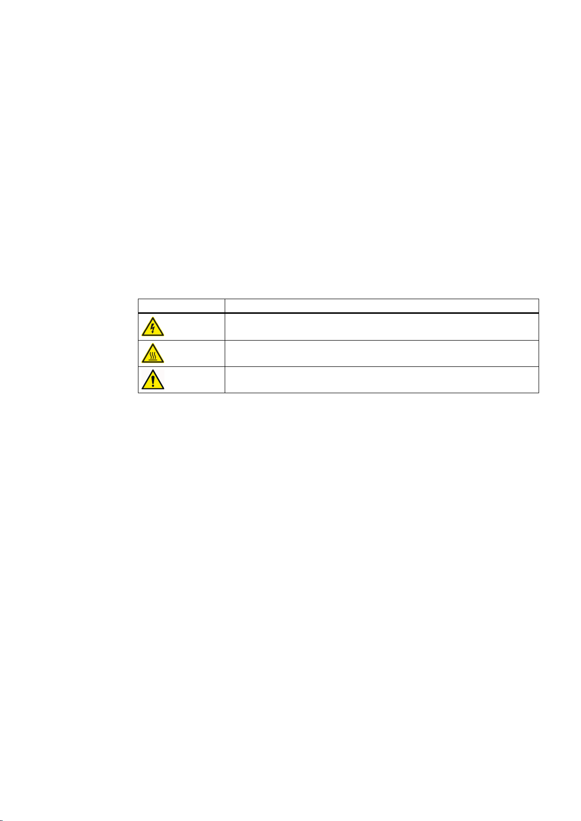
following meaning:
Warning symbol Meaning
Warning: Voltage
Warning: Hot surface
General warning symbol: Observe the explanations about the hazard on the
device labels.
For transportation, observe the "transportation markings (Page 76)" on the device packaging.
2
2.2 Qualified personnel
The product/system described in this documentation may only be operated by personnel
qualified for the specific task in accordance with the relevant documentation for the specific
task, in particular its warning notices and safety instructions. Because of their training and
experience, qualified personnel can recognize any risks involved with handling these products/
systems and avoid any possible dangers.
2.3 The five safety rules
For your own personal safety and to prevent material damage when carrying out any work,
always observe the safety-relevant instructions and the following five safety rules according
to EN 50110‑1 "Working in a voltage-free state". Apply the five safety rules in the sequence
stated before starting work.
Five safety rules
1. Disconnect the system.
Also disconnect the auxiliary circuits, for example, anti-condensation heating.
2. Secure against reconnection.
SINAMICS GM150 6SL3815-2LN41-4AA2
Operating Instructions 04/2017 19

Safety instructions
2.4 Safe handling
3. Verify absence of operating voltage.
4. Ground and short-circuit.
5. Provide protection against adjacent live parts.
To energize the system, apply the measures in reverse order.
2.4 Safe handling
WARNING
High voltages from external supplies
Even if the circuit breaker is open, parts of the drive can be under voltage (live) as a result of
the auxiliary voltage at the premagnetization, precharging or demagnetization transformers.
This danger is not limited to the drive, but can also occur with components that are electrically
connected to the drive (e.g. circuit breakers or isolators). Touching live parts can result in
death, serious injury, and damage to property.
● Isolate all components that can feed voltage to the converter before commencing work.
WARNING
High voltages during operation
When operating this equipment very high voltages develop. Even after switching off the mains
voltage, or while the connected machine is still turning, high voltages can remain for a
prolonged length of time. High voltages can cause death or serious injury if the safety rules
are not observed or if the equipment is handled incorrectly.
● Operate the drive properly.
● Always follow the "The five safety rules (Page 19)" when performing any work.
● Only remove the covers using the methods described by these operating instructions.
● Maintain the drive regularly and correctly.
WARNING
High voltages from machines still turning and connected
Rotating machinery can induce dangerous high voltages and synchronous motors that are
not de-excited immediately can also pose a hazard. If the connection to the motor is not
isolated or grounded, these voltages can also remain. Touching live parts can result in death
or serious injury.
● Before opening the doors, wait until the connected machine has come to a standstill.
SINAMICS GM150 6SL3815-2LN41-4AA2
20 Operating Instructions 04/2017

Safety instructions
2.4 Safe handling
WARNING
High voltages from DC link capacitors
High voltages are still present at the DC link capacitors even after shutdown. Touching live
parts can result in death or serious injury.
● A label on the converter specifies the discharge times of the DC link capacitors. Only open
the converter once these discharge times have expired.
● Observe the five safety rules when performing any work.
WARNING
High auxiliary voltages
High auxiliary voltages are still present even after shutdown. Touching live parts can result
in death or serious injury.
● Observe the five safety rules when performing any work.
WARNING
Hazardous arcing
Hazards caused by arcing can occur as result of the following factors, for example:
● The input currents are exceeded
● Incorrectly dimensioned circuit breaker or transformers
● Incorrectly connected cables or cables that have not been connected
● Excessive pollution
Arcing can result in death, serious injury or material damage.
● Make sure that the system is properly dimensioned and that the power cables are correctly
connected. The maximum permissible input currents are listed in the "Technical
specifications".
● Remove any excessive pollution.
WARNING
Live, moving or rotating parts
Contact with the parts mentioned can result in death, serious physical injury or damage to
property.
● Observe the instructions regarding installation and operation.
● Always take protective measures before touching any components.
● Do not remove any necessary covers.
SINAMICS GM150 6SL3815-2LN41-4AA2
Operating Instructions 04/2017 21

Safety instructions
2.4 Safe handling
WARNING
Hot component surfaces
Certain components (e.g. heat sinks and reactors) can become very hot during operation.
These components can remain hot for a long time after operation. Contact can result in serious
injury, such as skin burns.
● Do not touch hot components even after you have switched off the drive.
WARNING
Hot anti-condensation heating surface
When the temperature control limit value is reached the anti-condensation heating is switched
on. Once activated, the anti-condensation heating can generate a great deal of heat. Contact
can result in serious injury, such as skin burns.
● Ensure that the anti-condensation heating cannot be touched.
● Ensure that the anti-condensation heating is switched off before carrying out any repair
or maintenance work.
CAUTION
Places that are difficult to access
If you do not use appropriate protective equipment when working in places that are difficult
to access you are at risk of injury. For example, sharp edges and splinters can cause injuries
to the head and skin. If you use unsuitable steps when working on the upper areas of the
drive, you can fall and injure yourself.
● Use appropriate protective equipment, especially a hard hat and gloves.
● In the upper areas of the drive, use suitable steps.
CAUTION
Deionized water
Deionized water is harmful to eyes and skin and can damage surfaces.
● Therefore, use appropriate protective clothing for all work on the drive. However, if your
eyes or skin do come into contact with deionized water, rinse the affected area thoroughly
with tap water as soon as possible.
● If deionized water leaks out, eliminate the source of the problem and remove the liquid
from the surfaces affected.
SINAMICS GM150 6SL3815-2LN41-4AA2
22 Operating Instructions 04/2017

Safety instructions
2.5 Electromagnetic fields in electrical power engineering installations
NOTICE
Unsuitable residual current monitoring device
If you operate the drive together with a residual current monitoring device (RCD), it is possible
the residual current monitoring device will trip in error (nuisance trip). The drive may be
switched off as a result of the protection device tripping in error.
● To minimize the risk of faulty trips, use a type-B RCD.
2.5 Electromagnetic fields in electrical power engineering installations
Electromagnetic fields are generated during operation of electrical power engineering
installations. Electromagnetic fields can interfere with electronic devices, These devices can
malfunction if electromagnetic fields are present.
WARNING
Interference with pacemakers
The functioning of cardiac pacemakers could be impaired by electromagnetic fields. Death
or serious physical injury can result.
● It is therefore not permissible for people with pacemakers to stand close to the converter.
NOTICE
Data loss
Electromagnetic fields can cause data loss to magnetic or electronic data storage media.
● Therefore, do not carry magnetic or electronic data storage media with you.
Nominated persons in control of electrical installations can find further information on
electromagnetic fields under "Information for persons responsible for plants and systems."
SINAMICS GM150 6SL3815-2LN41-4AA2
Operating Instructions 04/2017 23

Safety instructions
2.6 Components that can be destroyed by electrostatic discharge (ESD)
2.6 Components that can be destroyed by electrostatic discharge (ESD)
ESD guidelines
NOTICE
Electrostatic discharge
Electronic components can be destroyed in the event of improper handling, transport, storage,
and shipping.
Pack the electronic components in appropriate ESD packaging; e.g. ESD foam, ESD
packaging bags and ESD transport containers.
To protect your equipment against damage, follow the instructions given below.
● Avoid physical contact with electronic components. If it is essential that you perform work
on these components, you must wear one of the following pieces of protective gear:
– Grounded ESD wrist strap
– ESD shoes or ESD shoe grounding strips if there is also an ESD floor.
● Do not place electronic components close to data terminals, monitors or televisions.
Maintain a minimum clearance to the screen (> 10 cm).
● Electronic components should not be brought into contact with electrically insulating
materials such as plastic foil, plastic parts, insulating table supports or clothing made of
synthetic fibers.
● Bring components into contact only with ESD-compliant materials, e.g. ESD tables, ESD
surfaces, ESD packaging.
● Only carry out measurements on the components if one of the following conditions is met:
– The measuring device is grounded with a protective conductor, for example.
– The measuring head of a floating measuring device has been discharged directly before
the measurement.
The necessary ESD protective measures for the entire working range for electrostatically
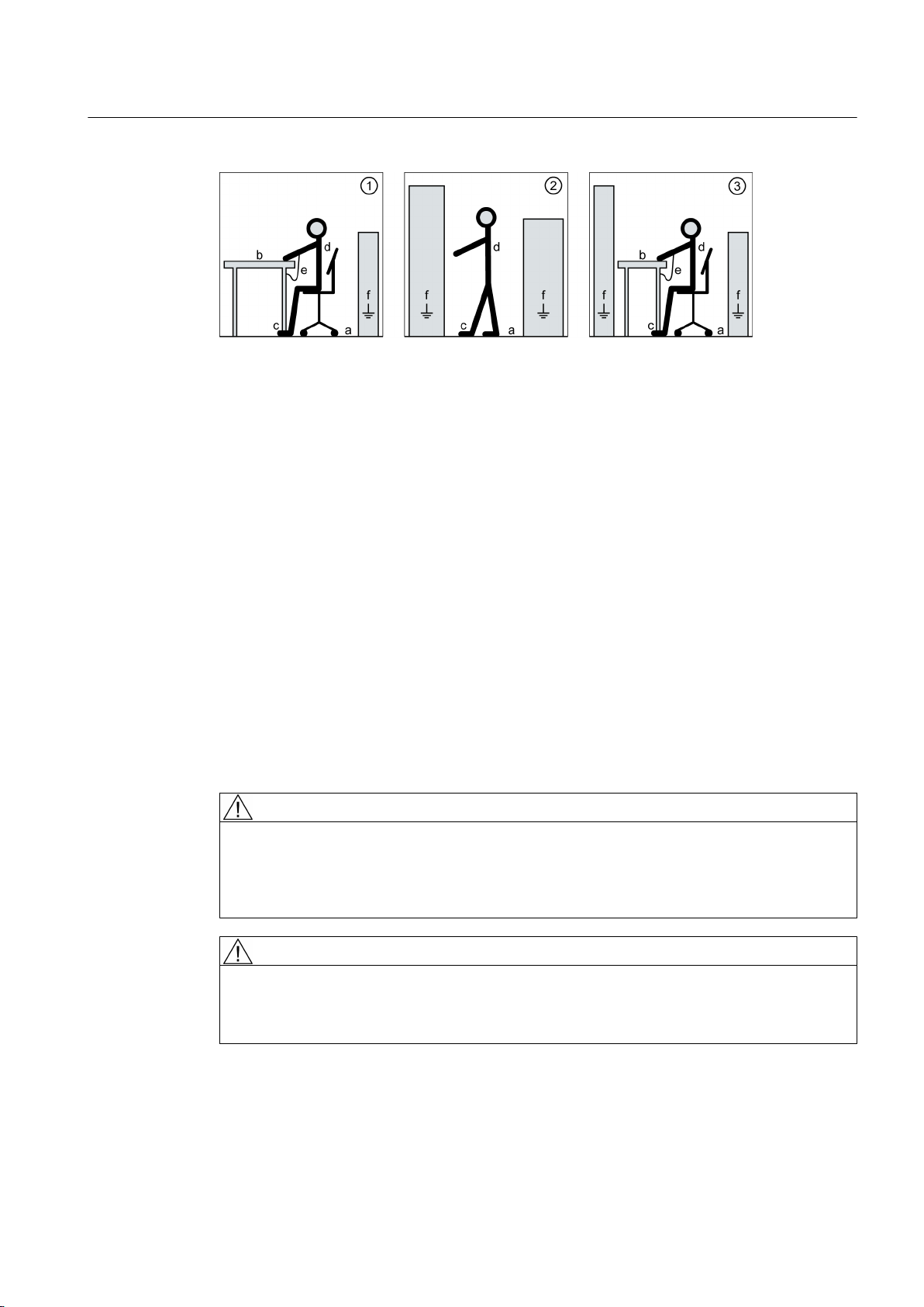
sensitive devices are illustrated once again in the following drawings.
Precise instructions for ESD protective measures are specified in the standard
DIN EN 61340‑5‑1.
SINAMICS GM150 6SL3815-2LN41-4AA2
24 Operating Instructions 04/2017
Safety instructions
2.7 Information for nominated persons in control of an electrical installation
① Sitting a Conductive floor cover‐
1)
ing
d ESD clothing
② Standing b ESD furniture e ESD wrist strap
③ Standing/sitting c Wearing of ESD shoes or
ESD shoe grounding
2)
strips
1)
Only effective in conjunction with ESD shoes or ESD shoe grounding strips
2)
Only effective in conjunction with conductive floor covering
f Cabinet ground connection
2.7 Information for nominated persons in control of an electrical
installation
2.7.1 Proper usage
The converters are intended to be used as a stationary installation in closed and dry rooms
with a clean atmosphere. You can find the ambient and operating temperatures to be adhered
to in the technical data. If the described environmental conditions are not observed, warranty
claims and other claims may be rejected.
WARNING
Explosions
If you operate the converter in a potentially explosive atmosphere, explosions can occur which
can cause death, serious injuries or material damage.
● Only operate the converter in a non-explosive environment (no hazardous zones).
WARNING
Non-observance of proper usage
Improper use of the devices described can result in death, severe injury or material damage.
● Please observe all instructions for proper use.
SINAMICS GM150 6SL3815-2LN41-4AA2
Operating Instructions 04/2017 25

Safety instructions
2.7 Information for nominated persons in control of an electrical installation
The nominated person in control of an electrical installation must ensure that the following
points are observed:
● Follow the local and industry-specific safety and setup regulations. Observe the
requirements in the guidelines specified in the "Standards and regulations" section of the
"Technical data and drawings." Ensure that the specific safety and construction regulations
and the regulations for using personal protective equipment are observed during all work.
● The operating instructions and the complete product documentation are always available
when carrying out any work.
● The technical data as well as the specifications relating to the permissible installation,
connection, ambient and operating conditions are taken into account at all times.
● Only qualified personnel or personnel supervised by responsible, skilled specialists are
allowed to carry out basic planning and all work on the converter.
● During shipping, specific transport conditions are adhered to.
● Assembly is performed according to assembly instructions. Separate cabinet units are
connected properly (cables and busbars).
● All instructions for EMC-compatible installation, cabling, shielding, grounding, and for
adequate auxiliary power supply are to be observed.
● Commissioning is only to be performed by qualified personnel trained for that purpose in
accordance with the commissioning instructions.
● System configuration is carried out by an experienced system integrator. Further system
components such as the circuit-breaker, transformer, cables, and motor are adjusted for
converter operation.
● The converter is only operated in conjunction with the engineered components.
● Different operating modes, overloads, load cycles, and differing environmental conditions
are permitted only after special arrangement with the manufacturer.
Note
Make use of the support and services offered by the relevant service center for planning,
installation, commissioning, and servicing work. You can find the relevant contact person under
"Service & Support".
2.7.2 Security information
Siemens provides products and solutions with industrial security functions that support the
secure operation of plants, systems, machines, and networks.
In order to protect plants, systems, machines and networks against cyber threats, it is
necessary to implement – and continuously maintain – a holistic, state-of-the-art industrial
security concept. Siemens’ products and solutions only form one element of such a concept.
Customer is responsible to prevent unauthorized access to its plants, systems, machines and
networks. Systems, machines and components should only be connected to the enterprise
network or the internet if and to the extent necessary and with appropriate security measures
(e.g. use of firewalls and network segmentation) in place.
SINAMICS GM150 6SL3815-2LN41-4AA2
26 Operating Instructions 04/2017

Additionally, Siemens’ guidance on appropriate security measures should be taken into
account. You can find more information about industrial security by visiting:
http://www.siemens.com/industrialsecurity.
Siemens’ products and solutions undergo continuous development to make them more secure.
Siemens strongly recommends to apply product updates as soon as available and to always
use the latest product versions. Use of product versions that are no longer supported, and
failure to apply latest updates may increase customer’s exposure to cyber threats.
To stay informed about product updates, subscribe to the Siemens Industrial Security RSS
Feed under
http://www.siemens.com/industrialsecurity.
2.7.3 Grounding concept
Create a grounding concept and integrate the converter within it. The grounding concept must
take into consideration national provisions and system specifics. Ensure that the following
criteria are fulfilled:
● Screw together the converter sub-units at the installation site, ensuring good conductivity.
Safety instructions
2.7 Information for nominated persons in control of an electrical installation
● If shield busbars are provided, these must be connected together.
● When the converter is supplied with power, the protective ground conductor must be
connected to the system's grounding point. Select the cross-section of the protective ground
conductor from one of the following variants:
– According to local wiring regulations
– Calculated according to IEC 60364-5-54, 543.1
– Half a phase conductor cross-section
2.7.4 Installation site safety
WARNING
Unsafe installation sites
This drive is used in industrial high-voltage installations. Improper use, incorrect operation,
insufficient maintenance, and access by unauthorized persons can lead to accidents. The
results can be death, serious bodily injury or damage to property.
● Install the drive in electrical rooms where only qualified personnel have access. If this is
not possible, then ensure that a barrier prevents uncontrolled access. Use safety fences
and appropriate signs, for example, to prevent unauthorized entry to the zone that has
been fenced off.
● Put up notices which indicate that only trained personnel are allowed to operate the drive
and carry out maintenance and repair work.
SINAMICS GM150 6SL3815-2LN41-4AA2
Operating Instructions 04/2017 27

Safety instructions
2.8 Residual risks
Note
Installations that include converters must be equipped with additional monitoring and protective
devices to fulfill safety requirements. Follow technical equipment legislation and accident
prevention regulations.
Note
The converter will be supplied on request without an electromechanical door interlocking
system if space is restricted. In this instance, the customer must provide an access interlock
system compliant with IEC 61800-5 /-1.
Note
The drive does not have a grounding breaker at the input/output. The system operator must,
therefore, ensure that there is sufficient grounding.
2.7.5 Measures for operator protection in electromagnetic fields
The plant operator is responsible for taking the following appropriate measures (labels and
hazard warnings) to adequately protect operating personnel against any possible risk.
● Observe the relevant nationally applicable health and safety regulations or the applicable
national regulations in the country of installation. In Germany, "electromagnetic fields" are
subject to regulations BGV B11 and BGR B11 stipulated by the German statutory industrial
accident insurance institution.
● Display adequate hazard warning notices on the installation.
● Place barriers around hazardous areas.
● Take measures, e.g. using shields, to reduce electromagnetic fields at their source.
● Make sure that personnel are wearing the appropriate protective gear.
2.8 Residual risks
According to the EU machinery directive, machine manufacturers / plant operators must
conduct a risk assessment of their machine. Plant operators must conduct a risk assessment
of their plant. In particular, pay attention to Annex 1 "General Principles" of the EU machinery
directive.
SINAMICS GM150 6SL3815-2LN41-4AA2
28 Operating Instructions 04/2017

Safety instructions
2.8 Residual risks
Pay attention to the following residual risks:
● Unintentional movements of driven machine parts
Unintentional movements of driven machine parts can occur during commissioning,
operation, maintenance, and repair, e.g. from the following causes:
– Hardware defects and/or software errors in the sensors, controllers, actuators, and
connection technology
– Response times of the controller and drive
– Operating and/or environmental conditions outside of the specification
– Condensation/conductive contamination
– Parameterization, programming, cabling, and installation errors
– Use of radio devices/cell phones in the immediate vicinity of the controller
– External influences/damage
● High temperatures and emissions
A fault can occur as a result of the following, for example:
– Component malfunctions
– Software errors
– Operating and/or environmental conditions outside of the specification
– External influences/damage
A fault can, for example, have the following consequences both inside and outside the drive:
– Extraordinarily high temperatures, including open fires as a result of the fault
– Emissions of light, noise, particles or gases
Converters with open type/IP20 protection must be installed in a distribution station or
comparable environment.
● Hazardous shock voltages
Hazardous shock voltages can result from the following causes, for example:
– Component malfunctions
– Induction of voltages in moving motors
– Operating and/or environmental conditions outside of the specification
– Condensation/conductive contamination
– External influences/damage
● The release of substances and emissions that are harmful to the environment
Improper operation or the improper disposal of components can harm the environment.
SINAMICS GM150 6SL3815-2LN41-4AA2
Operating Instructions 04/2017 29

Safety instructions
2.8 Residual risks
● Damage from pressure build-up during electric arcs in the event of a fault
If the dimensions of the building have not been designed correctly for the drive, damage
can result from the pressure that may build up inside.
● Dangerous electric arcs during internal faults
The drives are designed according to the relevant IEC standards and have been tested in
line with strict type-testing procedures. They were developed and manufactured so that
there is a very low probability of internal faults occurring. However, internal faults cannot
be completely ruled out.
WARNING
Dangerous electric arcs during internal faults
Defects such as damage to components, overvoltages, or loose parts, as well as exceptional
operating statuses, can cause a failure within the enclosure. This can result in an internal
electric arc. If an electric arc occurs and people are nearby, this could lead to death, serious
physical injury, and damage to property.
● Ensure that only qualified personnel perform work on the drive.
● Observe the safety and operating instructions in this documentation and on labels at the
drive for all work on the drive.
Note
There are no standards for medium-voltage drives stipulating requirements or inspections for
electric arc resistance. There is therefore neither formal guidance provided nor formal
certification available with regard to electric arc resistance.
SINAMICS GM150 6SL3815-2LN41-4AA2
30 Operating Instructions 04/2017
 Loading...