

Siemens SINAMICS GL150 Operating And Installation Instructions

www.siemens.com/drives
Operating Instructions
Installation Instructions
Medium-Voltage Drive
SINAMICS GL150
Type 6SL38503UM114PA0Z
Edition 04/2017

20.04.2017 14:02
V12.00

Medium-Voltage Drive
SINAMICS GL150
Type 6SL38503UM114PA0Z
Introduction
1
Operating Instructions
Installation Instructions
Safety information
Description
Preparations for use
Mounting
Electrical connection
Commissioning
Operation
2
3
4
5
6
7
8
Maintenance
Spare parts
Disposal
Service & Support
Technical specifications and
drawings
9
10
11
A
B
Edition 04/2017

Legal information
Warning notice system
This manual contains notices you have to observe in order to ensure your personal safety, as well as to prevent
damage to property. The notices referring to your personal safety are highlighted in the manual by a safety alert
symbol, notices referring only to property damage have no safety alert symbol. These notices shown below are
graded according to the degree of danger.
DANGER
indicates that death or severe personal injury will result if proper precautions are not taken.
WARNING
indicates that death or severe personal injury may result if proper precautions are not taken.
CAUTION
indicates that minor personal injury can result if proper precautions are not taken.
NOTICE
indicates that property damage can result if proper precautions are not taken.
If more than one degree of danger is present, the warning notice representing the highest degree of danger will be
used. A notice warning of injury to persons with a safety alert symbol may also include a warning relating to property
damage.
Qualified Personnel
The product/system described in this documentation may be operated only by personnel qualified for the specific
task in accordance with the relevant documentation, in particular its warning notices and safety instructions. Qualified
personnel are those who, based on their training and experience, are capable of identifying risks and avoiding
potential hazards when working with these products/systems.
Proper use of Siemens products
Note the following:
WARNING
Siemens products may only be used for the applications described in the catalog and in the relevant technical
documentation. If products and components from other manufacturers are used, these must be recommended or
approved by Siemens. Proper transport, storage, installation, assembly, commissioning, operation and
maintenance are required to ensure that the products operate safely and without any problems. The permissible
ambient conditions must be complied with. The information in the relevant documentation must be observed.
Trademarks
All names identified by ® are registered trademarks of Siemens AG. The remaining trademarks in this publication
may be trademarks whose use by third parties for their own purposes could violate the rights of the owner.
Disclaimer of Liability
We have reviewed the contents of this publication to ensure consistency with the hardware and software described.
Since variance cannot be precluded entirely, we cannot guarantee full consistency. However, the information in
this publication is reviewed regularly and any necessary corrections are included in subsequent editions.
Siemens AG
Process Industries and Drives
Postfach 48 48
90026 NÜRNBERG
GERMANY
Document order number: MUSTER
Ⓟ 04/2017 Subject to change
Copyright © Siemens AG 2013, -, 2016.
All rights reserved

Table of contents
1 Introduction.................................................................................................................................................13
1.1 About these instructions.........................................................................................................13
1.2 Text format features...............................................................................................................13
2 Safety information.......................................................................................................................................15
2.1 Warning symbol on the device...............................................................................................15
2.2 Qualified personnel................................................................................................................15
2.3 The five safety rules...............................................................................................................15
2.4 Safe handling.........................................................................................................................16
2.5 Electromagnetic fields in electrical power engineering installations ......................................18
2.6 Components that can be destroyed by electrostatic discharge (ESD)...................................19
2.7 Information for nominated persons in control of an electrical installation...............................21
2.7.1 Proper usage..........................................................................................................................21
2.7.2 Security information...............................................................................................................22
2.7.3 Grounding concept.................................................................................................................23
2.7.4 Installation site safety.............................................................................................................23
2.7.5 Instructions for inverters with no grounding switch................................................................24
2.7.6 Measures for operator protection in electromagnetic fields...................................................24
2.8 Residual risks.........................................................................................................................24
3 Description..................................................................................................................................................27
3.1 Area of application.................................................................................................................27
3.2 Safety concept.......................................................................................................................27
3.2.1 Safety components and functions..........................................................................................28
3.2.2 External safety components...................................................................................................28
3.2.3 Protection and monitoring functions of internal components.................................................29
3.2.4 Protection and monitoring functions for external components...............................................29
3.3 Power unit..............................................................................................................................29
3.3.1 Product features.....................................................................................................................29
3.3.2 Power unit components..........................................................................................................30
3.3.2.1 Power unit components of a starting converter (6/6-pulse drive system)..............................30
3.3.2.2 Thyristors...............................................................................................................................30
3.3.2.3 DC-link reactor.......................................................................................................................32
3.3.2.4 AVT combination module.......................................................................................................32
3.3.2.5 Power Stack Adapter.............................................................................................................33
3.3.2.6 Current transformer................................................................................................................33
3.3.2.7 Fans.......................................................................................................................................34
3.3.2.8 Differential-pressure switch....................................................................................................34
3.3.2.9 Surge suppressor...................................................................................................................34
3.3.2.10 Door limit switches.................................................................................................................34
3.3.3 Principle of operation.............................................................................................................35
SINAMICS GL150 6SL38503UM114PA0Z
Operating Instructions 04/2017 5

Table of contents
3.3.3.1 Fuseless technology..............................................................................................................35
3.3.3.2 Thyristor electronics...............................................................................................................36
3.3.3.3 Voltage actual value sensing.................................................................................................37
3.3.3.4 Ground fault detection............................................................................................................38
3.4 Closed-loop control................................................................................................................40
3.4.1 Structure of the open and closed loop control plate...............................................................40
3.4.2 Mushroom pushbutton...........................................................................................................40
3.4.3 Description of the components...............................................................................................41
3.4.3.1 SINAMICS Control Unit..........................................................................................................41
3.4.3.2 DRIVE-CLiQ interface............................................................................................................41
3.4.3.3 Voltage Sensing Module........................................................................................................41
3.4.3.4 Power supply unit...................................................................................................................42
3.4.3.5 Customer terminal strips........................................................................................................42
3.5 Options...................................................................................................................................42
3.5.1 Internal synchronizing voltage detection (option A11)...........................................................42
3.5.2 Damping switch for 1.4 kV (option C50).................................................................................42
3.5.3 Duty cycle (option C61)..........................................................................................................43
3.5.4 Black start (option E05)..........................................................................................................43
3.5.5 Brake after phase shifter operation (option E08)...................................................................43
3.5.6 Plug connection between the starting converter and excitation equipment (option G57) ......44
3.5.7 Temperature evaluation of the MV transformer (option K63).................................................45
3.5.8 Control Unit CU320-2 PN (option K95)..................................................................................45
3.5.9 Inductive cable attenuation (option L05)................................................................................45
3.5.10 Cabinet anti-condensation heating for the power unit (option L55)........................................46
3.5.11 Temperature-controlled and air-humidity-controlled anti-condensation heating (option
L58)........................................................................................................................................46
3.5.12 Dust protection (option M11)..................................................................................................46
3.5.13 Lock barrel (option M40)........................................................................................................47
3.5.14 Degree of protection IP41 (option M41).................................................................................47
3.5.15 Separate installation (M49)....................................................................................................47
3.5.16 Low-noise fan (option M65)....................................................................................................47
3.5.17 Customer-specific door stop for control cabinets (option M76)..............................................47
3.5.18 Line-side surge arresters (option N54)...................................................................................47
3.5.19 Machine-side surge arresters (option N56)............................................................................47
3.5.20 Line-side fuses (option N58)..................................................................................................48
3.5.21 Cabinet lighting in the power unit (option N86)......................................................................48
3.5.22 Customized locking system (option Y41)...............................................................................48
3.5.23 Customized duty cycle (option Y45).......................................................................................48
4 Preparations for use...................................................................................................................................49
4.1 Notes for system integrators..................................................................................................49
4.1.1 Requirements for transformers..............................................................................................49
4.1.2 Selection and configuration of multi-winding transformers.....................................................50
4.1.3 Requirements for the circuit breaker provided by the customer.............................................51
4.1.4 Requirements for cables........................................................................................................54
4.2 Requirements for installation location....................................................................................55
4.3 Inspections when receiving the delivery.................................................................................56
4.3.1 Checking the delivery.............................................................................................................56
4.3.2 Checking shock and tilt indicators..........................................................................................56
4.3.3 Checking the load handling attachments...............................................................................57
SINAMICS GL150 6SL38503UM114PA0Z
6 Operating Instructions 04/2017

Table of contents
4.4 Transportation........................................................................................................................58
4.4.1 Transport markings................................................................................................................58
4.4.2 Transport requirements..........................................................................................................58
4.4.3 Observe center of gravity.......................................................................................................59
4.4.4 Transport with a fork-lift truck.................................................................................................59
4.4.5 Transport with a crane...........................................................................................................60
4.4.6 Using lifting rods.....................................................................................................................60
4.4.7 Transporting transportation units packed in boxes................................................................62
4.5 Unpacking..............................................................................................................................63
4.5.1 Removing the packaging........................................................................................................63
4.5.2 Removing load securing devices...........................................................................................64
4.5.3 Lifting the cabinet off the transport pallet...............................................................................64
4.5.4 Opening doors in preparation for use.....................................................................................65
4.5.5 Checking the shock and tilt indicators inside the cabinet.......................................................65
4.6 Storage...................................................................................................................................66
4.6.1 Storing a device.....................................................................................................................66
4.6.2 Storing fans............................................................................................................................67
5 Mounting.....................................................................................................................................................69
5.1 Tools required........................................................................................................................70
5.2 Screwing the transport units together....................................................................................70
5.3 Connect to the foundation......................................................................................................71
5.4 Mounting fans.........................................................................................................................72
5.5 Ensuring cooling air................................................................................................................72
6 Electrical connection...................................................................................................................................73
6.1 Electromagnetic compatibility.................................................................................................75
6.2 Potential concept....................................................................................................................78
6.3 Connecting equipotential-bonding conductors.......................................................................78
6.4 Using the equipotential bonding strip and shield bus.............................................................79
6.5 Connecting the protective grounding.....................................................................................79
6.6 Laying the signal lines............................................................................................................80
6.7 Laying the cable shields.........................................................................................................80
6.8 Separating adjacent cabinets using unsuppressed contactors..............................................81
6.9 Laying additional wiring..........................................................................................................81
6.10 Connecting the power unit.....................................................................................................81
6.10.1 Connecting power cables.......................................................................................................81
6.10.2 Connecting the signal cables.................................................................................................83
6.11 Connecting the closed-loop control........................................................................................84
6.11.1 Connecting ground.................................................................................................................84
6.11.2 Connecting the auxiliary voltage............................................................................................84
6.11.3 Connecting circuit breakers....................................................................................................84
6.11.4 Connecting the external safety loop.......................................................................................85
SINAMICS GL150 6SL38503UM114PA0Z
Operating Instructions 04/2017 7

Table of contents
6.12 Interconnecting optional connections.....................................................................................85
6.13 Fastening the cable ducts with cable ties...............................................................................86
7 Commissioning...........................................................................................................................................87
8 Operation....................................................................................................................................................89
8.1 Parameters.............................................................................................................................90
8.2 Setpoint channel and closed-loop control..............................................................................91
8.2.1 Setpoint addition....................................................................................................................91
8.2.2 Direction of rotation changeover............................................................................................91
8.2.3 Suppression bandwidths........................................................................................................92
8.2.4 Speed limitation......................................................................................................................92
8.2.5 Ramp-function generator.......................................................................................................92
8.2.6 Vector control.........................................................................................................................93
8.3 Monitoring and protection functions.......................................................................................94
8.3.1 Safety shutdown of the converter...........................................................................................94
8.3.2 Speed monitoring with incremental encoder..........................................................................94
8.3.3 Uncontrolled stop, EMERGENCY STOP category 0.............................................................94
8.4 Fault and system messages..................................................................................................95
8.4.1 External warnings and faults..................................................................................................96
8.4.2 Diagnostics.............................................................................................................................96
8.4.2.1 Diagnostics via LEDs.............................................................................................................96
8.4.2.2 Diagnostics via parameters....................................................................................................97
8.4.2.3 Indicating and rectifying faults................................................................................................99
9 Maintenance.............................................................................................................................................101
9.1 Grounding the system..........................................................................................................104
9.2 Opening the device..............................................................................................................105
9.3 Preventive maintenance.......................................................................................................106
9.3.1 Checklist for preventive maintenance work..........................................................................106
9.3.2 Visual inspections................................................................................................................106
9.3.2.1 Equipment for visual inspections..........................................................................................106
9.3.2.2 Checking the isolating clearances........................................................................................107
9.3.2.3 Checking hoisting solenoids and security bolts....................................................................107
9.3.2.4 Checking the plug connections............................................................................................107
9.3.2.5 Checking the cable and screw terminals..............................................................................108
9.3.2.6 Checking the thyristor electronics........................................................................................108
9.3.2.7 Checking the filter mats........................................................................................................108
9.4 Maintenance.........................................................................................................................109
9.4.1 Replacing a fan....................................................................................................................109
9.4.2 Replacing the filter mats (option M11).................................................................................112
9.4.3 Replacing the back-up battery of the AOP30 operator panel ..............................................113
9.5 Cleaning...............................................................................................................................115
9.5.1 Removing dust deposits.......................................................................................................115
9.5.2 Cleaning aluminum parts.....................................................................................................115
9.6 Repairs.................................................................................................................................116
9.6.1 Torques................................................................................................................................118
9.6.2 Replacing the AVT combination module..............................................................................119
SINAMICS GL150 6SL38503UM114PA0Z
8 Operating Instructions 04/2017

Table of contents
9.6.3 Replacing the AOP30 operator panel..................................................................................120
9.6.4 Replacing the snubber circuit capacitor...............................................................................121
9.6.5 Replacing the CompactFlash card.......................................................................................121
9.6.6 Replacing the differential pressure monitor..........................................................................122
9.6.7 Replacing line-side fuses.....................................................................................................123
9.6.8 Replacing contactors............................................................................................................123
9.6.9 Replacing the current transformer........................................................................................124
9.6.10 Replacing the thyristor electronics and thyristors.................................................................124
9.6.10.1 Check components of the thyristor assembly......................................................................124
9.6.10.2 Replacing thyristor electronics.............................................................................................125
9.6.10.3 Replacing a thyristor............................................................................................................127
9.6.10.4 Disconnecting the fiber-optic cables....................................................................................129
9.6.11 Replacing the surge suppressor..........................................................................................130
9.6.12 Replacing the DC-link reactor..............................................................................................131
10 Spare parts...............................................................................................................................................133
11 Disposal....................................................................................................................................................135
11.1 Disposing of packaging material..........................................................................................135
11.2 Removing device components and old devices...................................................................135
A Service & Support.....................................................................................................................................137
A.1 Siemens Industry Online Support........................................................................................137
A.2 SIOS App.............................................................................................................................137
B Technical specifications and drawings.....................................................................................................139
B.1 Standards and regulations...................................................................................................139
B.2 General technical specifications...........................................................................................140
B.3 Technical specifications of power unit..................................................................................140
B.4 Technical data of the closed-loop control.............................................................................141
B.5 Control engineering properties.............................................................................................141
B.6 Environmental conditions.....................................................................................................142
B.7 Power unit............................................................................................................................143
B.7.1 Connection version, 6/6-pulse..............................................................................................143
B.7.2 Terminal blocks....................................................................................................................143
B.7.2.1 Auxiliary voltage supply........................................................................................................143
Index.........................................................................................................................................................145
Tables
Table 3-1 DRIVE-CLiQ interface.................................................................................................................41
Table 3-2 Connector assignment for voltages less than 60 V.....................................................................44
Table 3-3 Connector assignment for battery and voltages greater than 60 V (1AC)..................................44
Table 3-4 Connector assignment for voltages greater than 60 V (3 AC).....................................................44
Table 6-1 Cleaning agents and grease.......................................................................................................82
Table 8-1 LEDs of the Power Stack Adapters ............................................................................................96
SINAMICS GL150 6SL38503UM114PA0Z
Operating Instructions 04/2017 9

Table of contents
Table 9-1 Technical specifications of the backup battery..........................................................................113
Table 9-2 Tightening torque for screws.....................................................................................................118
Table 9-3 Tightening torques for screw terminals for copper cables without cable lug 1)..........................118
Table 9-4 Torques of the capacitor connections.......................................................................................121
Table B-1 Standards and regulations........................................................................................................139
Table B-2 General technical data..............................................................................................................140
Table B-3 General technical data..............................................................................................................140
Table B-4 General technical data..............................................................................................................140
Table B-5 General technical data..............................................................................................................141
Table B-6 Control engineering properties..................................................................................................141
Table B-7 Climatic environmental conditions.............................................................................................142
Table B-8 Mechanical ambient conditions.................................................................................................142
Table B-9 Other ambient conditions..........................................................................................................143
Table B-10 Terminal assignment for the auxiliary voltage supply................................................................143
Figures
Figure 3-1 Components of a starting converter for a 6/6-pulse drive system...............................................30
Figure 3-2 Clamped thyristor assembly........................................................................................................31
Figure 3-3 AVT combination module............................................................................................................32
Figure 3-4 Power Stack Adapter...................................................................................................................33
Figure 3-5 Short-circuiting sequence............................................................................................................36
Figure 3-6 Example: Components of the motor voltage sensing..................................................................37
Figure 3-7 Overview of the voltage sensing circuit.......................................................................................38
Figure 3-8 Operator protection, ground fault detection.................................................................................39
Figure 3-9 Open and closed loop control plate.............................................................................................40
Figure 3-10 Anti-condensation heating...........................................................................................................46
Figure 4-1 Two-tier design............................................................................................................................50
Figure 4-2 Example: Circuit-breaker control.................................................................................................53
Figure 4-3 Laying cables..............................................................................................................................54
Figure 4-4 Example of attaching and displaying the shock and tilt indicators..............................................57
Figure 4-5 Example illustration of centers of gravity.....................................................................................59
Figure 4-6 Lifting bar label............................................................................................................................61
Figure 4-7 Securing the lifting rods...............................................................................................................61
Figure 4-8 Transporting a transportation unit (still in packaging) with a crane.............................................63
Figure 4-9 Example: Cover screw for manual door interlocking...................................................................65
Figure 5-1 Screwing the transport units together..........................................................................................71
Figure 6-1 Shield connection using a clip.....................................................................................................77
Figure 6-2 Bridging shield gaps....................................................................................................................77
SINAMICS GL150 6SL38503UM114PA0Z
10 Operating Instructions 04/2017

Table of contents
Figure 6-3 Potential concept.........................................................................................................................78
Figure 6-4 Equipotential bonding conductor.................................................................................................78
Figure 6-5 Equipotential bonding strip..........................................................................................................79
Figure 6-6 Shield support.............................................................................................................................81
Figure 6-7 Example: Equipotential bonding conductor.................................................................................82
Figure 6-8 Schematic diagram: Fastening the cable ties..............................................................................86
Figure 8-1 Parameter types..........................................................................................................................90
Figure 9-1 Example: Grounding points.......................................................................................................104
Figure 9-2 Example: Securing the grounding spider in place.....................................................................105
Figure 9-3 Replacing the fan......................................................................................................................111
Figure 9-4 Schematic diagram: Replacing filter mats.................................................................................113
Figure 9-5 Replacing the backup battery....................................................................................................114
Figure 9-6 Example of an AVT combination module..................................................................................119
Figure 9-7 Replacing the operator panel....................................................................................................120
Figure 9-8 Line-side fuse............................................................................................................................123
Figure 9-9 Thyristor rack position...............................................................................................................125
Figure 9-10 Open-ended wrench in the groove of the guide bolt.................................................................128
Figure 9-11 Loosening the clamping screw with the socket wrench.............................................................128
Figure 9-12 Releasing a fiber-optic cable.....................................................................................................130
Figure B-1 6-pulse circuit on the line and motor sides.Number of thyristors connected in series 1 or 2).....143
SINAMICS GL150 6SL38503UM114PA0Z
Operating Instructions 04/2017 11

Table of contents
SINAMICS GL150 6SL38503UM114PA0Z
12 Operating Instructions 04/2017

Introduction
1.1 About these instructions
These instructions describe the drive and explain how to handle it, from initial delivery to final
disposal of the equipment. Keep these instructions for later use.
Read these instructions before you handle the drive and follow the instructions. The
instructions contain information about the safe handling of the drive as well as its components
and modules. They provide information on assembling, installing, and maintaining the
equipment properly.
If you have suggestions for improving the document, please contact our Service Center
(Page 137).
1.2 Text format features
Text format features
The warning notice system is explained on the rear of the inside front. Always follow the safety
instructions and notices in these instructions.
1
In addition to the safety-related warning notices which you must read, you will find the text in
these instructions is formatted in the following way:
1. Handling instructions are always formatted as a numbered list. Always perform the steps
in the order given.
● Lists are formatted as bulleted lists.
– Lists on the second level are hyphenated.
Note
A Note is an important item of information about the product, handling of the product or the
relevant section of the document. Notes provide you with help or further suggestions/ideas.
SINAMICS GL150 6SL38503UM114PA0Z
Operating Instructions 04/2017 13

Introduction
1.2 Text format features
SINAMICS GL150 6SL38503UM114PA0Z
14 Operating Instructions 04/2017
Safety information
In the individual chapters of this document, you will find safety instructions that must be obeyed
absolutely, for your own safety, to protect other people and to avoid damage to property. Pay
attention to the following safety instructions for all activities on the inverter.
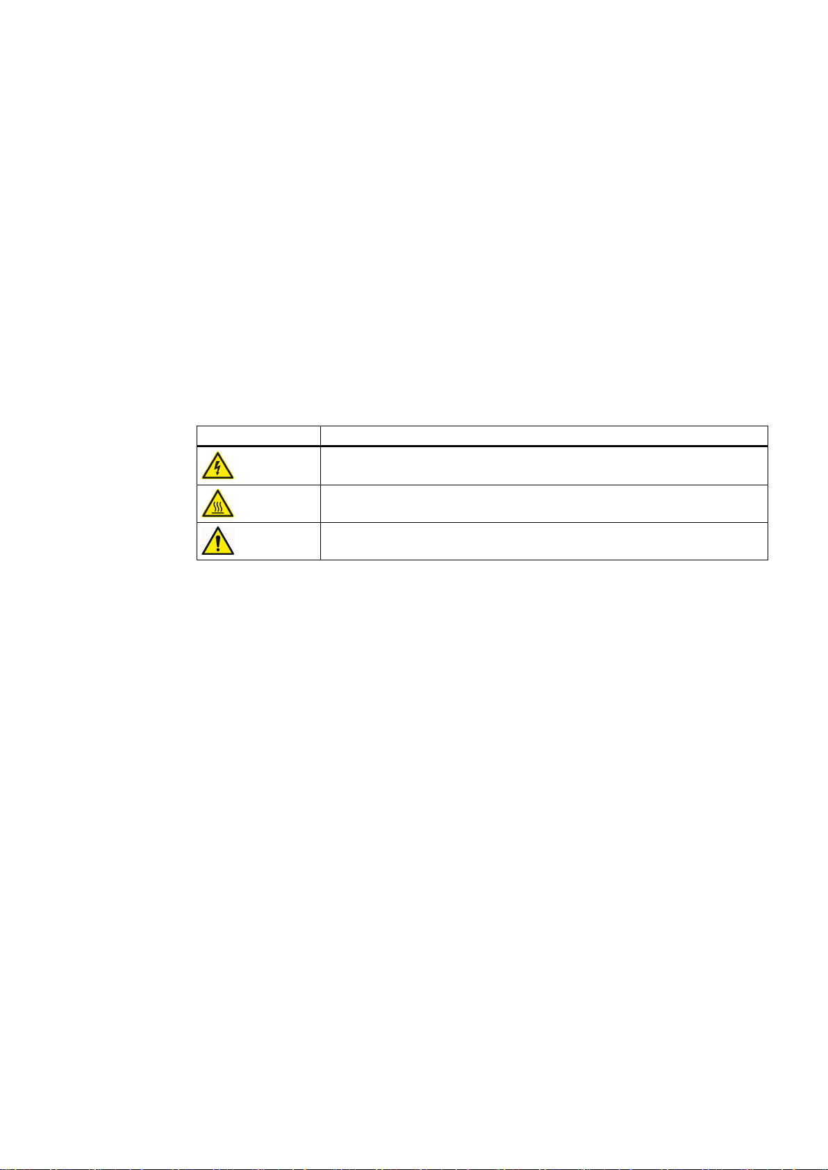
2.1 Warning symbol on the device
Please observe the warning symbols attached to the device. The warning symbols have the
following meaning:
Warning symbol Meaning
Warning: Voltage
Warning: Hot surface
General warning symbol: Observe the explanations about the hazard on the
device labels.
For transportation, observe the "transportation markings" on the device packaging.
2
2.2 Qualified personnel
The product/system described in this documentation may only be operated by personnel
qualified for the specific task in accordance with the relevant documentation for the specific
task, in particular its warning notices and safety instructions. Because of their training and
experience, qualified personnel can recognize any risks involved with handling these products/
systems and avoid any possible dangers.
2.3 The five safety rules
For your own personal safety and to prevent material damage when carrying out any work,
always observe the safety-relevant instructions and the following five safety rules according
to EN 50110‑1 "Working in a voltage-free state". Apply the five safety rules in the sequence
stated before starting work.
Five safety rules
1. Disconnect the system.
Also disconnect the auxiliary circuits, for example, anti-condensation heating.
2. Secure against reconnection.
SINAMICS GL150 6SL38503UM114PA0Z
Operating Instructions 04/2017 15

Safety information
2.4 Safe handling
3. Verify absence of operating voltage.
4. Ground and short-circuit.
5. Provide protection against adjacent live parts.
To energize the system, apply the measures in reverse order.
2.4 Safe handling
WARNING
High voltages from external supplies
Even if the circuit breaker is open, parts of the drive can be under voltage (live) as a result of
the auxiliary voltage at the premagnetization, precharging or demagnetization transformers.
This danger is not limited to the drive, but can also occur with components that are electrically
connected to the drive (e.g. circuit breakers or isolators). Touching live parts can result in
death, serious injury, and damage to property.
● Isolate all components that can feed voltage to the converter before commencing work.
WARNING
High voltages during operation
When operating this equipment very high voltages develop. Even after switching off the mains
voltage, or while the connected machine is still turning, high voltages can remain for a
prolonged length of time. High voltages can cause death or serious injury if the safety rules
are not observed or if the equipment is handled incorrectly.
● Operate the converter properly.
● Always observe the "The five safety rules (Page 15)" when carrying out any work.
● Only remove the covers using the methods described by these operating instructions.
● Maintain the converter regularly and correctly.
● After you have switched off the supply voltage, do not carry out any maintenance or repair
work until the one minute discharge time for the RC snubber circuit capacitor has elapsed.
WARNING
High voltages from machines still turning and connected
Rotating machinery can induce dangerous high voltages and synchronous motors that are
not de-excited immediately can also pose a hazard. If the connection to the motor is not
isolated or grounded, these voltages can also remain. Touching live parts can result in death
or serious injury.
● Before opening the doors, wait until the connected machine has come to a standstill.
SINAMICS GL150 6SL38503UM114PA0Z
16 Operating Instructions 04/2017

Safety information
2.4 Safe handling
WARNING
High auxiliary voltages
High auxiliary voltages are still present even after shutdown. Touching live parts can result
in death or serious injury.
● Observe the five safety rules when performing any work.
WARNING
Hazardous arcing
Hazards caused by arcing can occur as result of the following factors, for example:
● The input currents are exceeded
● Incorrectly dimensioned circuit breaker or transformers
● Incorrectly connected cables or cables that have not been connected
● Excessive pollution
Arcing can result in death, serious injury or material damage.
● Make sure that the system is properly dimensioned and that the power cables are correctly
connected. The maximum permissible input currents are listed in the "Technical
specifications".
● Remove any excessive pollution.
WARNING
Live, moving or rotating parts
Contact with the parts mentioned can result in death, serious physical injury or damage to
property.
● Observe the instructions regarding installation and operation.
● Always take protective measures before touching any components.
● Do not remove any necessary covers.
WARNING
Hot component surfaces
Certain components (e.g. heat sinks and reactors) can become very hot during operation.
These components can remain hot for a long time after operation. Contact can result in serious
injury, such as skin burns.
● Do not touch hot components even after you have switched off the drive.
SINAMICS GL150 6SL38503UM114PA0Z
Operating Instructions 04/2017 17

Safety information
2.5 Electromagnetic fields in electrical power engineering installations
WARNING
Hot anti-condensation heating surface
When the temperature control limit value is reached the anti-condensation heating is switched
on. Once activated, the anti-condensation heating can generate a great deal of heat. Contact
can result in serious injury, such as skin burns.
● Ensure that the anti-condensation heating cannot be touched.
● Ensure that the anti-condensation heating is switched off before carrying out any repair
or maintenance work.
CAUTION
Places that are difficult to access
If you do not use appropriate protective equipment when working in places that are difficult
to access you are at risk of injury. For example, sharp edges and splinters can cause injuries
to the head and skin. If you use unsuitable steps when working on the upper areas of the
drive, you can fall and injure yourself.
● Use appropriate protective equipment, especially a hard hat and gloves.
● In the upper areas of the drive, use suitable steps.
NOTICE
Unsuitable residual current monitoring device
If you operate the drive together with a residual current monitoring device (RCD), it is possible
the residual current monitoring device will trip in error (nuisance trip). The drive may be
switched off as a result of the protection device tripping in error.
● To minimize the risk of faulty trips, use a type-B RCD.
2.5 Electromagnetic fields in electrical power engineering installations
Electromagnetic fields are generated during operation of electrical power engineering
installations. Electromagnetic fields can interfere with electronic devices, These devices can
malfunction if electromagnetic fields are present.
WARNING
Interference with pacemakers
The functioning of cardiac pacemakers could be impaired by electromagnetic fields. Death
or serious physical injury can result.
● It is therefore not permissible for people with pacemakers to stand close to the converter.
SINAMICS GL150 6SL38503UM114PA0Z
18 Operating Instructions 04/2017

Safety information
2.6 Components that can be destroyed by electrostatic discharge (ESD)
NOTICE
Data loss
Electromagnetic fields can cause data loss to magnetic or electronic data storage media.
● Therefore, do not carry magnetic or electronic data storage media with you.
Nominated persons in control of electrical installations can find further information on
electromagnetic fields under "Information for persons responsible for plants and systems."
See also
Information for nominated persons in control of an electrical installation (Page 21)
2.6 Components that can be destroyed by electrostatic discharge (ESD)
ESD guidelines
NOTICE
Electrostatic discharge
Electronic components can be destroyed in the event of improper handling, transport, storage,
and shipping.
Pack the electronic components in appropriate ESD packaging; e.g. ESD foam, ESD
packaging bags and ESD transport containers.
To protect your equipment against damage, follow the instructions given below.
● Avoid physical contact with electronic components. If it is essential that you perform work
on these components, you must wear one of the following pieces of protective gear:
– Grounded ESD wrist strap
– ESD shoes or ESD shoe grounding strips if there is also an ESD floor.
● Do not place electronic components close to data terminals, monitors or televisions.
Maintain a minimum clearance to the screen (> 10 cm).
● Electronic components should not be brought into contact with electrically insulating
materials such as plastic foil, plastic parts, insulating table supports or clothing made of
synthetic fibers.
SINAMICS GL150 6SL38503UM114PA0Z
Operating Instructions 04/2017 19
Safety information
2.6 Components that can be destroyed by electrostatic discharge (ESD)
● Bring components into contact only with ESD-compliant materials, e.g. ESD tables, ESD
surfaces, ESD packaging.
● Only carry out measurements on the components if one of the following conditions is met:
– The measuring device is grounded with a protective conductor, for example.
– The measuring head of a floating measuring device has been discharged directly before
the measurement.
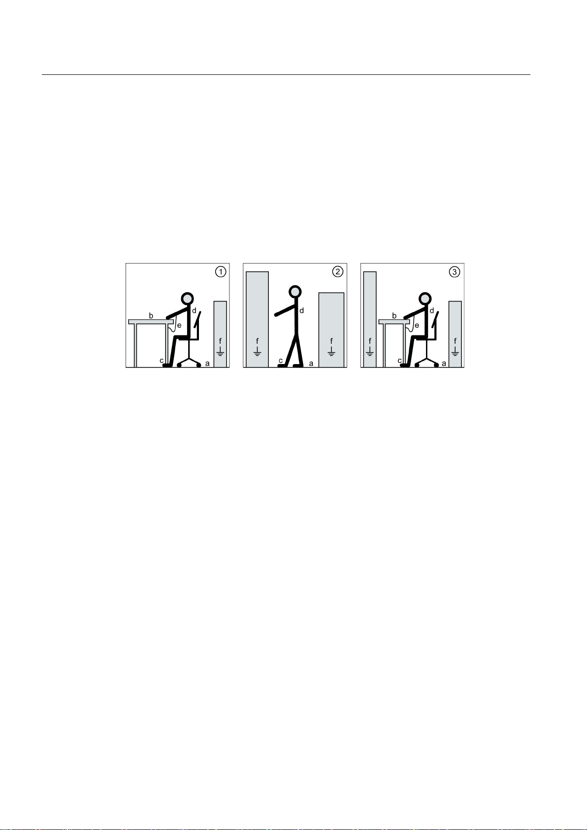
The necessary ESD protective measures for the entire working range for electrostatically
sensitive devices are illustrated once again in the following drawings.
Precise instructions for ESD protective measures are specified in the standard
DIN EN 61340‑5‑1.
① Sitting a Conductive floor cover‐
1)
ing
d ESD clothing
② Standing b ESD furniture e ESD wrist strap
③ Standing/sitting c Wearing of ESD shoes or
ESD shoe grounding
2)
strips
1)
Only effective in conjunction with ESD shoes or ESD shoe grounding strips
2)
Only effective in conjunction with conductive floor covering
f Cabinet ground connection
SINAMICS GL150 6SL38503UM114PA0Z
20 Operating Instructions 04/2017

Safety information
2.7 Information for nominated persons in control of an electrical installation
2.7 Information for nominated persons in control of an electrical
installation
2.7.1 Proper usage
The converters are intended to be used as a stationary installation in closed and dry rooms
with a clean atmosphere. You can find the ambient and operating temperatures to be adhered
to in the technical data. If the described environmental conditions are not observed, warranty
claims and other claims may be rejected.
WARNING
Explosions
If you operate the converter in a potentially explosive atmosphere, explosions can occur which
can cause death, serious injuries or material damage.
● Only operate the converter in a non-explosive environment (no hazardous zones).
WARNING
Non-observance of proper usage
Improper use of the devices described can result in death, severe injury or material damage.
● Please observe all instructions for proper use.
The nominated person in control of an electrical installation must ensure that the following
points are observed:
● Follow the local and industry-specific safety and setup regulations. Observe the
requirements in the guidelines specified in the "Standards and regulations" section of the
"Technical data and drawings." Ensure that the specific safety and construction regulations
and the regulations for using personal protective equipment are observed during all work.
● The operating instructions and the complete product documentation are always available
when carrying out any work.
● The technical data as well as the specifications relating to the permissible installation,
connection, ambient and operating conditions are taken into account at all times.
● Only qualified personnel or personnel supervised by responsible, skilled specialists are
allowed to carry out basic planning and all work on the converter.
● During shipping, specific transport conditions are adhered to.
● Assembly is performed according to assembly instructions. Separate cabinet units are
connected properly (cables and busbars).
● All instructions for EMC-compatible installation, cabling, shielding, grounding, and for
adequate auxiliary power supply are to be observed.
● Commissioning is only to be performed by qualified personnel trained for that purpose in
accordance with the commissioning instructions.
SINAMICS GL150 6SL38503UM114PA0Z
Operating Instructions 04/2017 21

Safety information
2.7 Information for nominated persons in control of an electrical installation
● System configuration is carried out by an experienced system integrator. Further system
components such as the circuit-breaker, transformer, cables, and motor are adjusted for
converter operation.
● The converter is only operated in conjunction with the engineered components.
● Different operating modes, overloads, load cycles, and differing environmental conditions
are permitted only after special arrangement with the manufacturer.
Note
Make use of the support and services offered by the relevant service center for planning,
installation, commissioning, and servicing work. You can find the relevant contact person under
"Service & Support (Page 137)".
See also
Standards and regulations (Page 139)
2.7.2 Security information
Siemens provides products and solutions with industrial security functions that support the
secure operation of plants, systems, machines and networks.
In order to protect plants, systems, machines and networks against cyber threats, it is
necessary to implement – and continuously maintain – a holistic, state-of-the-art industrial
security concept. Siemens’ products and solutions only form one element of such a concept.
Customer is responsible to prevent unauthorized access to its plants, systems, machines and
networks. Systems, machines and components should only be connected to the enterprise
network or the internet if and to the extent necessary and with appropriate security measures
(e.g. use of firewalls and network segmentation) in place.
Additionally, Siemens’ guidance on appropriate security measures should be taken into
account. For more information about industrial security, please visit:
http://www.siemens.com/industrialsecurity
Siemens’ products and solutions undergo continuous development to make them more secure.
Siemens strongly recommends to apply product updates as soon as available and to always
use the latest product versions. Use of product versions that are no longer supported, and
failure to apply latest updates may increase customer’s exposure to cyber threats.
To stay informed about product updates, subscribe to the Siemens Industrial Security RSS
Feed under:
http://www.siemens.com/industrialsecurity
SINAMICS GL150 6SL38503UM114PA0Z
22 Operating Instructions 04/2017

2.7 Information for nominated persons in control of an electrical installation
2.7.3 Grounding concept
Create a grounding concept and integrate the converter within it. The grounding concept must
take into consideration national provisions and system specifics. Ensure that the following
criteria are fulfilled:
● Screw together the converter sub-units at the installation site, ensuring good conductivity.
● If shield busbars are provided, these must be connected together.
● When the converter is supplied with power, the protective ground conductor must be
connected to the system's grounding point. Select the cross-section of the protective ground
conductor from one of the following variants:
– According to local wiring regulations
– Calculated according to IEC 60364-5-54, 543.1
– Half a phase conductor cross-section
2.7.4 Installation site safety
Safety information
WARNING
Unsafe installation sites
This drive is used in industrial high-voltage installations. Improper use, incorrect operation,
insufficient maintenance, and access by unauthorized persons can lead to accidents. The
results can be death, serious bodily injury or damage to property.
● Install the drive in electrical rooms where only qualified personnel have access. If this is
not possible, then ensure that a barrier prevents uncontrolled access. Use safety fences
and appropriate signs, for example, to prevent unauthorized entry to the zone that has
been fenced off.
● Put up notices which indicate that only trained personnel are allowed to operate the drive
and carry out maintenance and repair work.
Note
Installations that include converters must be equipped with additional monitoring and protective
devices to fulfill safety requirements. Follow technical equipment legislation and accident
prevention regulations.
Note
The converter will be supplied on request without an electromechanical door interlocking
system if space is restricted. In this instance, the customer must provide an access interlock
system compliant with IEC 61800-5 /-1.
SINAMICS GL150 6SL38503UM114PA0Z
Operating Instructions 04/2017 23

Safety information
2.8 Residual risks
2.7.5 Instructions for inverters with no grounding switch
Note
The drive does not have a grounding breaker at the input/output. The system operator must,
therefore, ensure that there is sufficient grounding.
2.7.6 Measures for operator protection in electromagnetic fields
The plant operator is responsible for taking the following appropriate measures (labels and
hazard warnings) to adequately protect operating personnel against any possible risk.
● Observe the relevant nationally applicable health and safety regulations or the applicable
national regulations in the country of installation. In Germany, "electromagnetic fields" are
subject to regulations BGV B11 and BGR B11 stipulated by the German statutory industrial
accident insurance institution.
● Display adequate hazard warning notices on the installation.
● Place barriers around hazardous areas.
● Take measures, e.g. using shields, to reduce electromagnetic fields at their source.
● Make sure that personnel are wearing the appropriate protective gear.
2.8 Residual risks
According to the EU machinery directive, machine manufacturers / plant operators must
conduct a risk assessment of their machine. Plant operators must conduct a risk assessment
of their plant. In particular, pay attention to Annex 1 "General Principles" of the EU machinery
directive.
SINAMICS GL150 6SL38503UM114PA0Z
24 Operating Instructions 04/2017

Safety information
2.8 Residual risks
Pay attention to the following residual risks:
● Unintentional movements of driven machine parts
Unintentional movements of driven machine parts can occur during commissioning,
operation, maintenance, and repair, e.g. from the following causes:
– Hardware defects and/or software errors in the sensors, controllers, actuators, and
connection technology
– Response times of the controller and drive
– Operating and/or environmental conditions outside of the specification
– Condensation/conductive contamination
– Parameterization, programming, cabling, and installation errors
– Use of radio devices/cell phones in the immediate vicinity of the controller
– External influences/damage
● High temperatures and emissions
A fault can occur as a result of the following, for example:
– Component malfunctions
– Software errors
– Operating and/or environmental conditions outside of the specification
– External influences/damage
A fault can, for example, have the following consequences both inside and outside the drive:
– Extraordinarily high temperatures, including open fires as a result of the fault
– Emissions of light, noise, particles or gases
Converters with open type/IP20 protection must be installed in a distribution station or
comparable environment.
● Hazardous shock voltages
Hazardous shock voltages can result from the following causes, for example:
– Component malfunctions
– Induction of voltages in moving motors
– Operating and/or environmental conditions outside of the specification
– Condensation/conductive contamination
– External influences/damage
● The release of substances and emissions that are harmful to the environment
Improper operation or the improper disposal of components can harm the environment.
SINAMICS GL150 6SL38503UM114PA0Z
Operating Instructions 04/2017 25

Safety information
2.8 Residual risks
● Damage from pressure build-up during electric arcs in the event of a fault
If the dimensions of the building have not been designed correctly for the drive, damage
can result from the pressure that may build up inside.
● Dangerous electric arcs during internal faults
The drives are designed according to the relevant IEC standards and have been tested in
line with strict type-testing procedures. They were developed and manufactured so that
there is a very low probability of internal faults occurring. However, internal faults cannot
be completely ruled out.
WARNING
Dangerous electric arcs during internal faults
Defects such as damage to components, overvoltages, or loose parts, as well as exceptional
operating statuses, can cause a failure within the enclosure. This can result in an internal
electric arc. If an electric arc occurs and people are nearby, this could lead to death, serious
physical injury, and damage to property.
● Ensure that only qualified personnel perform work on the drive.
● Observe the safety and operating instructions in this documentation and on labels at the
drive for all work on the drive.
Note
There are no standards for medium-voltage drives stipulating requirements or inspections for
electric arc resistance. There is therefore neither formal guidance provided nor formal
certification available with regard to electric arc resistance.
SINAMICS GL150 6SL38503UM114PA0Z
26 Operating Instructions 04/2017

Description
3.1 Area of application
The current-source DC-link converter is used for continuous speed adjustment of synchronous
motors with continuous power above 1 MW. The converter is suitable for four-quadrant
operation without additional expenditure. This means driving and braking are possible in both
directions.
Starting converter
The output frequency typically lies between 0 and 50/60 Hz. The converter is used as a starting
device for the following driven machines, for example:
● Blowers
● Fans
● Compressors
● Gas-turbine sets
● Hydroelectric power generators
● Large synchronous motors on weak power systems
3
Continuous-duty converter
The output frequency typically lies between 0 and 105 Hz. The converter is used for the
variable-speed drive of the following driven machines, for example:
● Blowers
● Fans
● Pumps
● Turbo-compressors
● Reciprocating compressors
● Extruders and mixers
● Continuous-flow conveyors
● Marine propellers
● Drive in rod mills
3.2 Safety concept
The converter and its components are subject to a comprehensive safety concept. When used
properly, the security concept guarantees safe installation, safe operation as well as safe
service and maintenance.
SINAMICS GL150 6SL38503UM114PA0Z
Operating Instructions 04/2017 27

Description
3.2 Safety concept
The safety concept encompasses safety components and functions to protect the device and
operators. The converter is also equipped with monitoring functions to protect external
components.
The converter operates safely when the interlock and protection systems are functioning
properly. Nevertheless, there are areas on the converter that are hazardous for personnel and
that cause material damage if the safety information of all the instructions and the labels on
the converter are not strictly observed.
3.2.1 Safety components and functions
Shock protection is ensured by means of a housing that conforms to EN 60204-11.
Monitoring of the door limit switches causes the converter to switch off if one of the doors of
the power unit is opened.
DANGER
Insufficient grounding
High voltages are still present in the converter even after it has been shut down. If live parts
are touched, this can result in death or severe injury.
The converter does not have a grounding breaker. The system operator must, therefore,
ensure that there is sufficient grounding.
Ensure sufficient grounding during work on the power unit. Further information on grounding
can be found under "Safety information for maintenance and repairs".
See also
Grounding the system (Page 104)
3.2.2 External safety components
The safety concept of the converter is supplemented by the following external components:
● Circuit breaker
You can find more detailed information in the section "Circuit breaker (provided by the
customer)".
● Input-side transformer
When an error is detected, the medium-voltage transformer limits the short-circuit current
and is configured in such a way that the maximum permissible short-circuit current (see the
technical data) is not exceeded.
SINAMICS GL150 6SL38503UM114PA0Z
28 Operating Instructions 04/2017

3.2.3 Protection and monitoring functions of internal components
The internal components of the converter have the following protection and monitoring
functions:
● Converter protection based on monitoring systems:
– Current monitoring
– Output voltage monitoring
– Indirect thermal monitoring of the DC link reactor
– Supply voltage monitoring
– Circuit breaker monitoring
– Monitoring the fans
● Shutdown in the event of semiconductor failure
● Shutdown in the event of control component failure
● Internal protection functions for the control hardware
Description
3.3 Power unit
● Protection against communication failure between the closed-loop control and the power
unit
● Anti-condensation heating
3.2.4 Protection and monitoring functions for external components
Transformer and motor can be monitored in the drive. A fast protective shutdown that you can
activate for external problems, e.g. short-circuits, is present.
3.3 Power unit
3.3.1 Product features
In the standard version, the power unit has the following product features:
● Simple configuration
● Relatively low semiconductor requirements
● Fuseless design
● Line-side converter
● Motor-side converter
● Voltage actual value sensing on the motor side
● DC-link-side and machine-side actual current value acquisition
SINAMICS GL150 6SL38503UM114PA0Z
Operating Instructions 04/2017 29

Description
3.3 Power unit
● Line-side and machine-side overvoltage protection with spark-gap-free metal-oxide surge
arresters
● DC link reactor for decoupling the line-side converter from the motor-side converter
● Power cables connected from below
3.3.2 Power unit components
3.3.2.1 Power unit components of a starting converter (6/6-pulse drive system)
The diagram below shows an example of the typical components of a starting converter for a
6/6-pulse drive system:
① Circuit breaker
② Surge suppressor (metal-oxide disks, without spark gaps)
③ Line-side converter
④ Air-cooled DC link reactor, installed in a cabinet
⑤ Motor-side converter
⑥ Motor voltage sensing (U
sensing)
M
⑦ Current transformer in the DC link
⑧ Converter transformer
⑨ Synchronizing transformer or converter
Figure 3-1 Components of a starting converter for a 6/6-pulse drive system
3.3.2.2 Thyristors
One or two of the thyristor stacks are used for a 6-pulse bridge. They differ in the number of
pick-offs from the heat sinks. The thyristor stacks are equipped with various thyristors and
corresponding RC (resistor, capacitor) circuitry. Six thyristors are braced in one clamped
thyristor assembly.
SINAMICS GL150 6SL38503UM114PA0Z
30 Operating Instructions 04/2017
 Loading...