

Siemens SINAMICS G180 Installation And Operating Instructions Manual


___________________
___________________
___________________
___________________
___________________
___________________
___________________
___________________
___________________
___________________
___________________
___________________
___________________
___________________
___________________
SINAMICS
Installation and Operating
Instructions SINAMICS G180
Operating Instructions
Translation of the original instructions
02/2019
4BS0751
Introduction
1
Safety information
2
Description
3
Preparations for use
4
Installation
5
Electrical connection
6
Commissioning
7
Operation
8
Maintenance
9
Spare parts
10
Diagnostics, faults and
warnings
11
Service & Support
A
Quality documents
B
Technical data
C
List of abbreviations
D
-007

Siemens AG
Division Process Industries and Drives
P
90026 NÜRNBERG
GERMANY
Document order number: 4BS0751
Ⓟ
Copyright © Siemens AG 2019.
All rights reserved
Legal information
Warning notice system
DANGER
indicates that death or severe personal injury will result if proper precautions are not taken.
WARNING
indicates that death or severe personal injury may result if proper precautions are not taken.
CAUTION
indicates that minor personal injury can result if proper precautions are not taken.
NOTICE
indicates that property damage can result if proper precautions are not taken.
Qualified Personnel
personnel qualified
Proper use of Siemens products
WARNING
Siemens products may only be used for the applications described in the catalog and in the relevant technical
ambient conditions must be complied with. The information in the relevant documentation must be observed.
Trademarks
Disclaimer of Liability
This manual contains notices you have to observe in order to ensure your personal safety, as well as to prevent
damage to property. The notices referring to your personal safety are highlighted in the manual by a safety alert
symbol, notices referring only to property damage have no safety alert symbol. These notices shown below are
graded according to the degree of danger.
If more than one degree of danger is present, the warning notice representing the highest degree of danger will
be used. A notice warning of injury to persons with a safety alert symbol may also include a warning relating to
property damage.
The product/system described in this documentation may be operated only by
task in accordance with the relevant documentation, in particular its warning notices and safety instructions.
Qualified personnel are those who, based on their training and experience, are capable of identifying risks and
avoiding potential hazards when working with these products/systems.
Note the following:
documentation. If products and components from other manufacturers are used, these must be recommended
or approved by Siemens. Proper transport, storage, installation, assembly, commissioning, operation and
maintenance are required to ensure that the products operate safely and without any problems. The permissible
All names identified by ® are registered trademarks of Siemens AG. The remaining trademarks in this publication
may be trademarks whose use by third parties for their own purposes could violate the rights of the owner.
We have reviewed the contents of this publication to ensure consistency with the hardware and software
described. Since variance cannot be precluded entirely, we cannot guarantee full consistency. However, the
information in this publication is reviewed regularly and any necessary corrections are included in subsequent
editions.
for the specific
ostfach 48 48
02/2019 Subject to change

Table of contents
1 Introduction ............................................................................................................................................. 9
2 Safety information ................................................................................................................................. 13
3 Description ............................................................................................................................................ 31
1.1 About these instructions............................................................................................................ 9
1.2 Validity ...................................................................................................................................... 9
1.3 Text format features .................................................................................................................. 9
1.4 Presentation of the display buttons in the operating instructions ........................................... 10
1.5 Specific features ..................................................................................................................... 10
2.1 The five safety rules ................................................................................................................ 13
2.2 Use of tested, certified and Siemens-approved components ................................................. 14
2.3 Areas that are potentially and particularly hazardous ............................................................. 15
2.4 Notes for operator protection .................................................................................................. 16
2.5 Notes on liquid cooling ............................................................................................................ 19
2.6 Safety precautions when handling anti-freeze ........................................................................ 20
2.7 Standards and guidelines for proper use of inverters ............................................................. 21
2.8 Plant safety ............................................................................................................................. 22
2.9 Security information ................................................................................................................ 23
2.10 Components that can be destroyed by electrostatic discharge (ESD) ................................... 24
2.11 Electromagnetic fields ............................................................................................................. 26
2.12 Radio telephones and mobile telephones .............................................................................. 27
2.13 Note regarding fiber-optic cables ............................................................................................ 28
2.14 Protecting/fusing the external 230 V AC control voltage ........................................................ 28
2.15 Residual risks .......................................................................................................................... 29
3.1 Updating inverter software or instructions .............................................................................. 31
3.2 Order numbers / Type designations ....................................................................................... 31
3.3 Accessories ............................................................................................................................. 37
3.3.1 Use of tested, certified and Siemens-approved components ................................................. 37
3.3.2 Peripheral boards 1 to 4, -A95, option G02 to G05 ................................................................ 37
3.3.2.1 General information about the peripheral boards 1 to 4 ......................................................... 37
3.3.2.2 Electronic shutdown for "Safe halt" / PTC inputs .................................................................... 39
3.3.2.3 "Safe torque off" with single circuit trip ................................................................................... 42
3.3.2.4 "Safe torque off" with two circuit version ................................................................................. 43
3.3.2.5 Switchover, single circuit <-> two circuit tripping .................................................................... 43
3.3.2.6 Checking the "Safe halt" function ........................................................................................... 45
Installation and Operating Instructions SINAMICS G180
Operating Instructions, 02/2019, 4BS0751-007
3

Table of contents
4 Preparations for use .............................................................................................................................. 71
5 Installation ............................................................................................................................................ 83
3.3.2.7 PTC inputs for motor PTC thermistor..................................................................................... 47
3.3.3 Brake transistor and brake resistor ........................................................................................ 49
3.3.3.1 Dimensioning the brake resistor ............................................................................................ 49
3.3.3.2 Connecting the brake resistor ................................................................................................ 49
3.3.4 Parameter overview ............................................................................................................... 50
3.3.5 "Factory settings" application ................................................................................................. 50
3.3.6 Protective cover IP21 for compact and compact Plus devices .............................................. 51
3.3.7 Main switch "Q 2T..." or "W 2T..." .......................................................................................... 52
3.3.8 DC link terminals for compact devices ................................................................................... 52
3.3.9 External display ...................................................................................................................... 54
3.3.10 RFI suppression filter, category C1 (class B) ........................................................................ 55
3.3.11 Strengthened du/dt filter ......................................................................................................... 55
3.3.12 Sine-wave filter....................................................................................................................... 55
3.3.13 Additional mains power protection chokes ............................................................................ 55
3.3.14 Optional fieldbus connection .................................................................................................. 56
3.3.14.1 PROFIBUS DP ....................................................................................................................... 56
3.3.14.2 PROFINET IO ........................................................................................................................ 57
3.3.14.3 Modbus RTU .......................................................................................................................... 60
3.3.14.4 Modbus TCP .......................................................................................................................... 63
3.3.15 Pre-switch mode power supply 300 W .................................................................................. 65
3.3.16 Water cooling ......................................................................................................................... 66
3.3.16.1 General information about water cooling ............................................................................... 66
3.3.16.2 Direct water cooling diagram ................................................................................................. 67
3.3.16.3 Connecting water cooling ....................................................................................................... 68
3.3.16.4 Venting the water cooling ....................................................................................................... 68
3.3.16.5 Decommissioning and shutdown ........................................................................................... 69
3.3.16.6 Cooling water additives for the closed inverter cooling with cooling unit (optional) ............... 69
4.1 Transporting inverter .............................................................................................................. 71
4.2 Storage of the inverters .......................................................................................................... 74
4.3 EMC ....................................................................................................................................... 75
4.3.1 Install and connect in accordance with EMC. ........................................................................ 75
4.3.2 Examples for correct EMC connection .................................................................................. 76
4.3.3 Radio interference class ........................................................................................................ 78
4.3.4 EMC environment category ................................................................................................... 79
4.4 Realizing operation in the explosion-protected zone ............................................................. 80
5.1 Installing inverter - General notes .......................................................................................... 83
5.2 Installing compact devices ..................................................................................................... 84
5.3 Protective cover IP21 for compact and compact Plus devices .............................................. 85
5.4 Installing cabinet units ............................................................................................................ 86
5.5 Mounting an external display (option) .................................................................................... 88
Installation and Operating Instructions SINAMICS G180
4 Operating Instructions, 02/2019, 4BS0751-007

Table of contents
6 Electrical connection ............................................................................................................................. 91
7 Commissioning ................................................................................................................................... 115
8 Operation ............................................................................................................................................ 123
6.1 General information about the electrical connection .............................................................. 91
6.2 Protecting the inverter ............................................................................................................. 92
6.3 Circuit breaker ......................................................................................................................... 92
6.4 Connecting control cable ........................................................................................................ 93
6.5 Line supply connection ........................................................................................................... 93
6.5.1 Suitable supply line configurations ......................................................................................... 93
6.5.2 Dimensioning mains power cables ......................................................................................... 94
6.5.3 RCD circuit breaker ................................................................................................................. 94
6.5.4 Connecting mains power cable to the inverter ....................................................................... 95
6.5.5 Inverter connection for different pulse operation .................................................................... 96
6.5.6 Adjusting the line voltage at the inverter ................................................................................. 97
6.6 Motor connection .................................................................................................................... 98
6.6.1 Motor selection ........................................................................................................................ 98
6.6.2 Coil load .................................................................................................................................. 99
6.6.3 Motor voltage and type of circuit ............................................................................................. 99
6.6.4 Dimensioning motor cables .................................................................................................. 100
6.6.5 Dimensioning maximum motor cable length ......................................................................... 100
6.6.6 Connecting motor cable ........................................................................................................ 102
6.6.7 Connecting the PTC thermistor of the motor to the inverter ................................................. 102
6.7 External control voltage ........................................................................................................ 103
6.7.1 Use of external control voltage ............................................................................................. 103
6.7.2 Connecting the external 230 V AC control voltage ............................................................... 103
6.7.2.1 Protecting/fusing the external 230 V AC control voltage ...................................................... 103
6.7.2.2 Switching over the hardware to an external 230 V AC control voltage ................................ 104
6.7.2.3 Preparations for accessing the "switching power supply" board .......................................... 104
6.7.2.4 Connecting the external 230 V AC for compact devices ...................................................... 111
6.7.2.5 Control voltage 230 V AC for cabinet units ........................................................................... 111
6.7.3 Connecting the external 24 V DC control voltage ................................................................. 112
6.7.3.1 Protecting/fusing the external 24 V DC control voltage ........................................................ 112
6.7.3.2 Switching over the hardware to an external 24 V DC control voltage .................................. 112
7.1 Checks without mains power supply and without motor ....................................................... 115
7.2 Checks with mains power supply and without motor ............................................................ 117
7.3 Checks with mains power supply and with motor ................................................................. 121
7.4 Checking with motor coupled to the work machine .............................................................. 122
8.1 Operation .............................................................................................................................. 123
8.1.1 Function of the inverter display ............................................................................................. 123
8.1.2 Switching the unit on and off ................................................................................................. 125
8.1.3 Setting the language ............................................................................................................. 125
8.1.4 Setting the date and time ...................................................................................................... 126
8.1.5 Setting the level of detail of the inverter menu ..................................................................... 126
8.1.6 Inverter operating commands ............................................................................................... 126
8.1.7 Configuring operating sources .............................................................................................. 128
Installation and Operating Instructions SINAMICS G180
Operating Instructions, 02/2019, 4BS0751-007
5

Table of contents
8.1.8 Invoking mode configurations .............................................................................................. 128
8.1.9 Communication Options ....................................................................................................... 129
8.1.10 Meaning of the abbreviations for operating functions .......................................................... 130
8.1.11 "P-fieldbus" function ............................................................................................................. 130
8.1.12 Function of "P-DIGITAL OUTPUTS" .................................................................................... 131
8.1.13 Function of "P-ANALOG OUTPUTS" ................................................................................... 131
8.1.14 Operation of several inverters on one PC ............................................................................ 131
8.1.15 Communication via PROFINET IO ...................................................................................... 132
8.1.15.1 Communication services and port numbers used for PROFINET IO .................................. 132
8.1.15.2 Overview .............................................................................................................................. 133
8.1.15.3 Network security................................................................................................................... 134
8.1.15.4 Separation between production and office networks ........................................................... 134
8.1.15.5 Network segmentation with SCALANCE S .......................................................................... 135
8.2 Standard mode settings ....................................................................................................... 135
8.2.1 Mode "std siss" ..................................................................................................................... 135
8.2.2 Mode "std sisd" .................................................................................................................... 136
8.2.3 Mode "std dids" .................................................................................................................... 137
8.2.4 Mode "std didd" .................................................................................................................... 138
8.3 NAMUR mode settings ........................................................................................................ 138
8.3.1 Operation according to NAMUR defaults ............................................................................. 138
8.3.2 Operation according to "NAMUR 1" ..................................................................................... 139
8.3.3 Operation according to "NAMUR 2" ..................................................................................... 140
8.3.4 Operation according to "NAMUR 3" ..................................................................................... 141
8.3.5 Operation according to "NAMUR 4" ..................................................................................... 142
8.3.6 Operation according to "NAMUR 5" ..................................................................................... 143
8.3.7 Operation according to "NAMUR 6" ..................................................................................... 144
8.4 Controlling the external connections of the inverter............................................................. 145
8.4.1 Function of the control cable terminals ................................................................................ 145
8.4.2 Protective separation according to EN 61800-5-1 ............................................................... 145
8.4.3 Sub-D and USB connections and DIL switches ................................................................... 148
8.4.4 USB interface ....................................................................................................................... 149
8.4.5 DIL switches "S1" and "S2" .................................................................................................. 149
8.4.6 Connecting encoders ........................................................................................................... 151
8.4.7 Connect the PC via USB at -X50B....................................................................................... 153
8.4.8 Connecting a PC to -X51 via RS 232................................................................................... 154
8.4.9 Connection for optional external display with RS 485 ......................................................... 155
8.5
Special functions .................................................................................................................. 156
8.5.1 Protective functions .............................................................................................................. 156
8.5.2 Multiple function of the analog and digital inputs ................................................................. 160
8.6 Setpoint channel and closed-loop control ............................................................................ 164
8.6.1 Specifying source for speed setpoint ................................................................................... 164
8.7 Parameterization .................................................................................................................. 164
8.7.1 Principle of operation of the configuration ........................................................................... 164
8.7.2 Protecting parameters against modification ......................................................................... 166
8.7.3 Configuration using the inverter display ............................................................................... 166
8.7.4 More documentation about parameterization ...................................................................... 167
Installation and Operating Instructions SINAMICS G180
6 Operating Instructions, 02/2019, 4BS0751-007

Table of contents
9 Maintenance ....................................................................................................................................... 181
10 Spare parts ......................................................................................................................................... 185
11 Diagnostics, faults and warnings ......................................................................................................... 187
A Service & Support ............................................................................................................................... 189
B Quality documents .............................................................................................................................. 191
8.8 Examples / Applications ........................................................................................................ 168
8.8.1 "Standard" application ........................................................................................................... 168
8.8.1.1 Standard control cable terminals .......................................................................................... 168
8.8.1.2 Control cable terminals "peripheral board 1" ........................................................................ 169
8.8.1.3 Control cable terminals "peripheral board 2" ........................................................................ 169
8.8.1.4 Control cable terminals "peripheral board 3" ........................................................................ 170
8.8.1.5 Control cable terminals "peripheral board 4" ........................................................................ 171
8.8.1.6 Mode setting of the "Standard" application ........................................................................... 171
8.8.1.7 Assignment of the digital inputs ............................................................................................ 172
8.8.1.8 Assignment of the digital outputs .......................................................................................... 172
8.8.1.9 Assignment of the analog inputs ........................................................................................... 172
8.8.1.10 Assignment of the analog outputs ........................................................................................ 173
8.8.1.11 Input "Safe torque off" / PTC thermistor inputs on peripheral board .................................... 173
8.8.2 "NAMUR" application ............................................................................................................ 175
8.8.2.1 Control cable terminals for "NAMUR" application ................................................................. 175
8.8.2.2 Control cable terminals "peripheral board 4" ........................................................................ 177
8.8.2.3 Mode setting of the NAMUR application ............................................................................... 178
8.8.2.4 Assignment of the relay outputs ........................................................................................... 178
8.8.2.5 Assignment of the analog inputs ........................................................................................... 179
8.8.2.6 Assignment of the analog outputs ........................................................................................ 179
8.8.2.7 Input "Mandatory mains power isolation" / PTC thermistor inputs on peripheral board ....... 179
9.1 Maintenance and servicing ................................................................................................... 181
9.2 Replacing compact device .................................................................................................... 182
9.3 Replacing fans for the compact device ................................................................................. 183
9.4 Maintenance and service of water cooling (option) .............................................................. 183
9.5 Decommissioning .................................................................................................................. 183
10.1 Non-approved spare parts .................................................................................................... 185
10.2 Spare parts ........................................................................................................................... 185
11.1 Reading event log ................................................................................................................. 188
A.1 Contacts in Ruhstorf an der Rott location (Germany) ........................................................... 190
Installation and Operating Instructions SINAMICS G180
Operating Instructions, 02/2019, 4BS0751-007
7

Table of contents
C Technical data ..................................................................................................................................... 193
D List of abbreviations ............................................................................................................................. 211
Index ................................................................................................................................................... 213
C.1 Technical data for transportation ......................................................................................... 194
C.2 Technical data for storage ................................................................................................... 194
C.3 Frame sizes of compact units .............................................................................................. 195
C.4 Frame sizes of cabinet units ................................................................................................ 197
C.5 Technical data for operation ................................................................................................ 200
C.6 Tightening torques for power cables .................................................................................... 201
C.7 Technical data of the control cable terminals ...................................................................... 201
C.8 Technical data and identification of the PTC thermistor input at peripheral boards 2
and 4 .................................................................................................................................... 203
C.9 Technical data of the direct water cooling ........................................................................... 204
C.10 Permissible substance values for the cooling water ............................................................ 205
C.11 Threshold values for fan control system .............................................................................. 206
C.12 Derating ................................................................................................................................ 206
C.12.1 Current derating ................................................................................................................... 206
C.12.2 Voltage derating ................................................................................................................... 209
Installation and Operating Instructions SINAMICS G180
8 Operating Instructions, 02/2019, 4BS0751-007

1
1.1
About these instructions
1.2
Validity
1.3
Text format features
Text format features
Note
The note provides you with additional information about the product itself, handling the
product
These Operating Instructions describe the device and provide you with information about
handling it - from the initial shipment up to disposal. Keep these instructions for later use.
Read these Operating Instructions and comply with the information provided in them. In this
way you can ensure safe, problem-free operation and a long service life.
Safety information and handling-related warnings are provided in these Operating
Instructions. For your own safety, the safety of other persons and to avoid material damage,
carefully follow these instructions when carrying out any work.
If you have suggestions for improving the document, please contact our Service Center.
This document is applicable for SINAMICS G180 T7 (not capable of energy recovery), Order
number "6SE01…", from software version 11C0242/CF78
You can find the following text format features in these instructions:
1. Handling instructions are always formatted as a numbered list. Always perform the steps
● Lists are formatted as bulleted lists.
in the order given.
– Lists on the second level are hyphenated.
- and the relevant documentation.
Installation and Operating Instructions SINAMICS G180
Operating Instructions, 02/2019, 4BS0751-007
9
Introduction
1.4
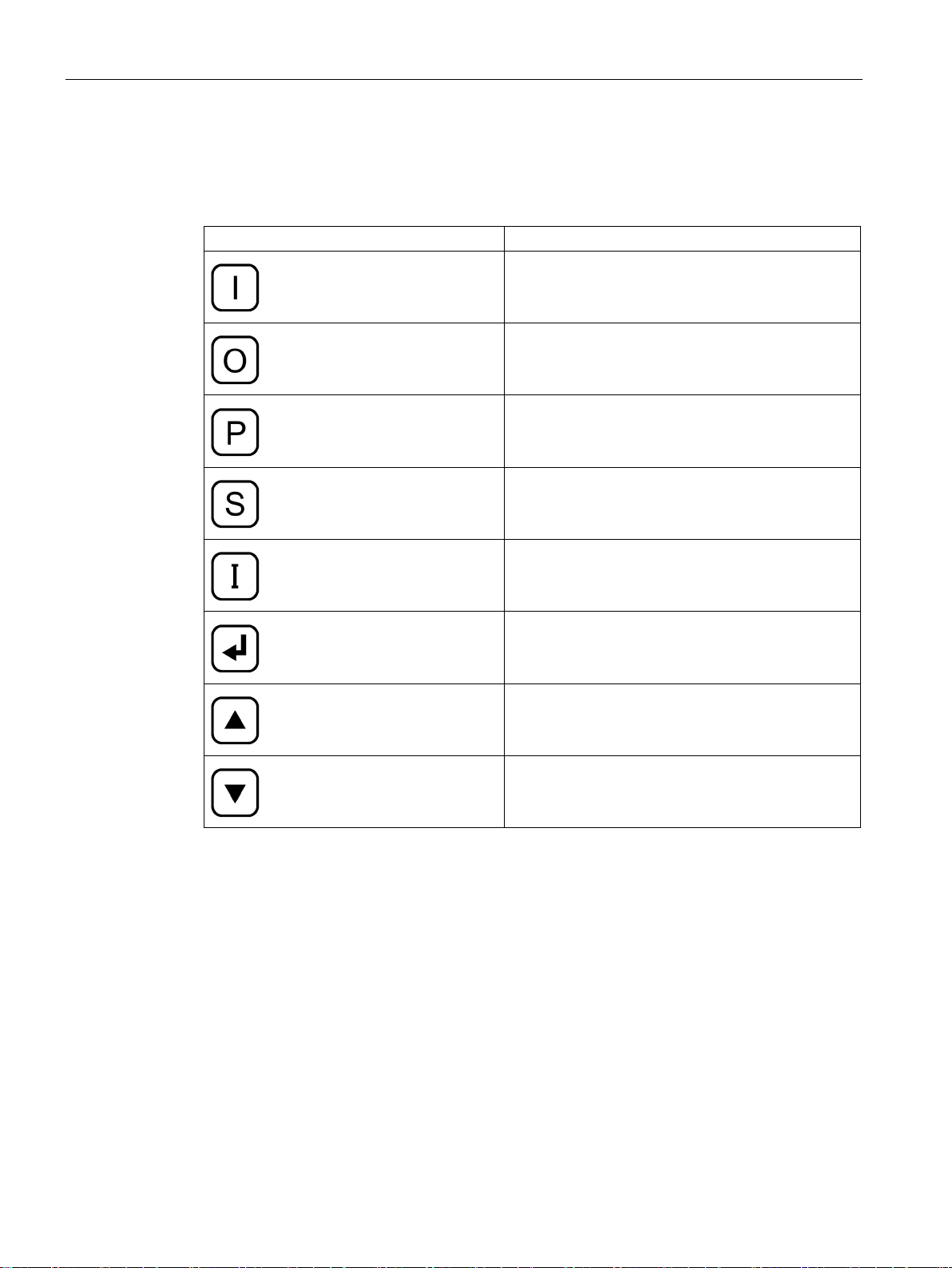
Presentation of the display buttons in the operating instructions
Button on the inverter display
Presentation in the text
1.5
Specific features
1.4 Presentation of the display buttons in the operating instructions
Table 1- 1 Presentation of the display buttons in the text
<On>
<Off>
<P>
<S>
<I>
<ENTER>
<up arrow>
<down arrow>
The following text formats are used in this operating manual.
Installation and Operating Instructions SINAMICS G180
10 Operating Instructions, 02/2019, 4BS0751-007

Introduction
Display buttons
Description in the text
Meaning
<Arrow up>
Press the button on the control panel once.
<S+I>
Press both buttons simultaneously.
Display text
"
1.5 Specific features
Table 1- 2 Display of special markings
<Arrow up_ Arrow up> Press the button on the control panel twice.
"P-SYSTEM DATA"
Text shown in the control panel display is presented like this.
If you have to branch in a menu, the text will be shown as follows:
P-MACHINE POWER CONV/P-speed default/t-accel.". "P-MACHINE POWER CONV"
symbolizes the main menu, "P-speed default" the submenu and "t-accel." the parameter.
In this case, you parameterize the accelerating time in the corresponding menu. Several
submenus can be nested.
Installation and Operating Instructions SINAMICS G180
Operating Instructions, 02/2019, 4BS0751-007
11

Introduction
1.5 Specific features
Installation and Operating Instructions SINAMICS G180
12 Operating Instructions, 02/2019, 4BS0751-007
2
2.1
The five safety rules
Five safety rules
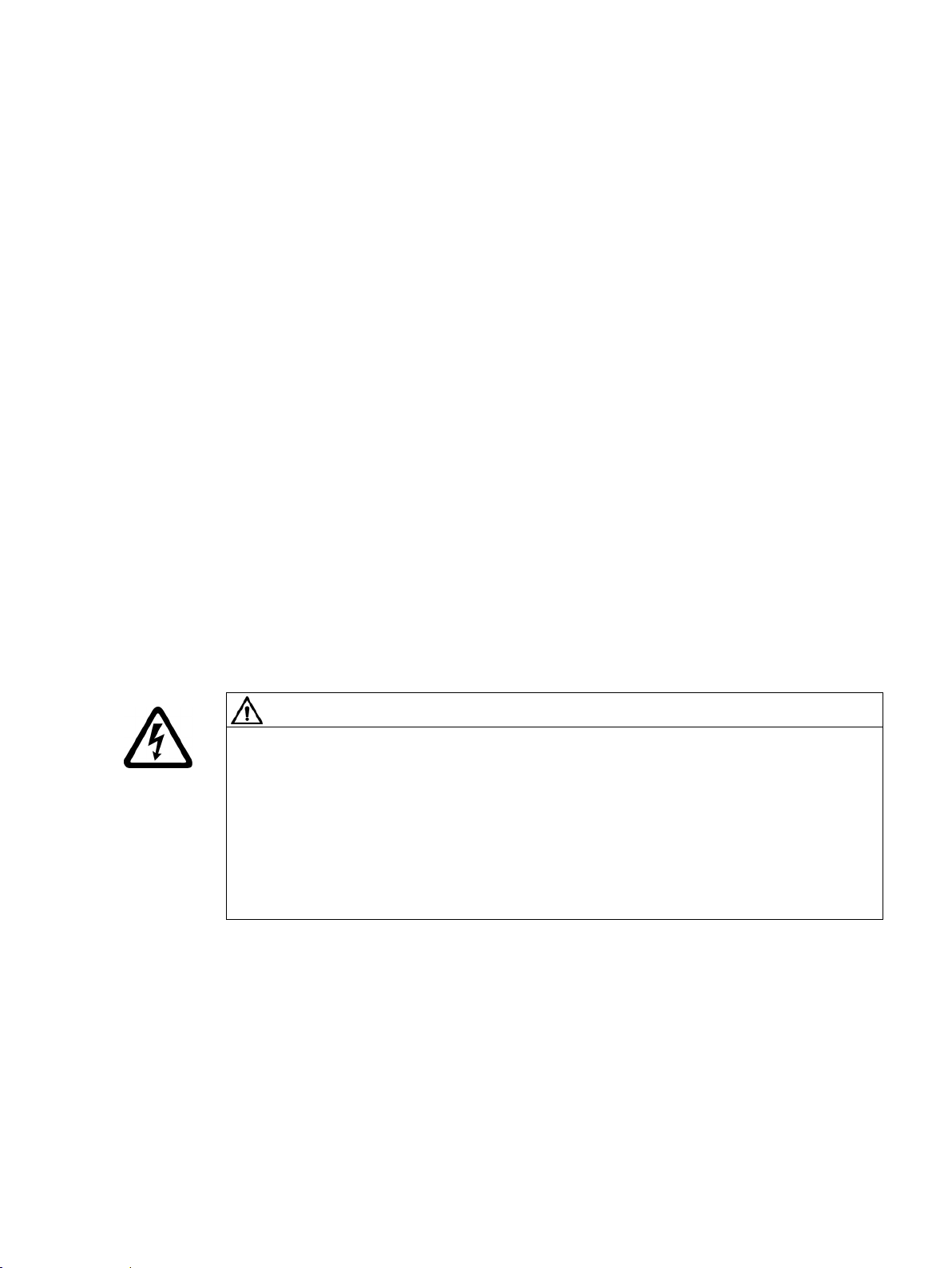
DANGER
High voltages
For your personal safety and in order to prevent material damage it is essential that you
adhere to all the safety notices contained in your product documentation. Pay particular
attention to the safety notices on the product itself. When working on the equipment, always
observe the following five safety rules as defined by EN 50110-1 "Working in a voltage-free
state". Apply the five safety rules in the sequence stated before starting work.
1. Disconnect the system.
Disconnect the auxiliary circuits, for example anti-condensation heating.
Wait until the capacitors have discharged.
2. Lockout to protect against reconnection.
3. Make sure that the equipment is de-energized and in a no-voltage condition.
4. Ground and short-circuit.
5. Cover or enclose adjacent components that are still live.
When you have finished working on the equipment, apply the measures in reverse order.
Potentially fatal voltages occur when this equipment is in operation which can remain
present even after the inverter is switched off.
High voltages cause death, serious injury or material damage if the safety instructions are
not observed or if the equipment is handled improperly.
• Ensure that only qualified and authorized personnel perform work on the inverter.
• Always observe the five safety rules specified above whenever you are carrying out any
work on the device.
Installation and Operating Instructions SINAMICS G180
Operating Instructions, 02/2019, 4BS0751-007
13

Safety information
2.2
Use of tested, certified and Siemens-approved components
WARNING
Components which are not approved
2.2 Use of tested, certified and Siemens-approved components
Observe the following instructions if you would like to integrate your own components in the
system.
It is dangerous to use components which are not tested, not certified and not approved by
Siemens. This can result in death, serious injury or material damage.
• Use only components which are tested, certified and approved by Siemens.
Installation and Operating Instructions SINAMICS G180
14 Operating Instructions, 02/2019, 4BS0751-007
Safety information
2.3
Areas that are potentially and particularly hazardous
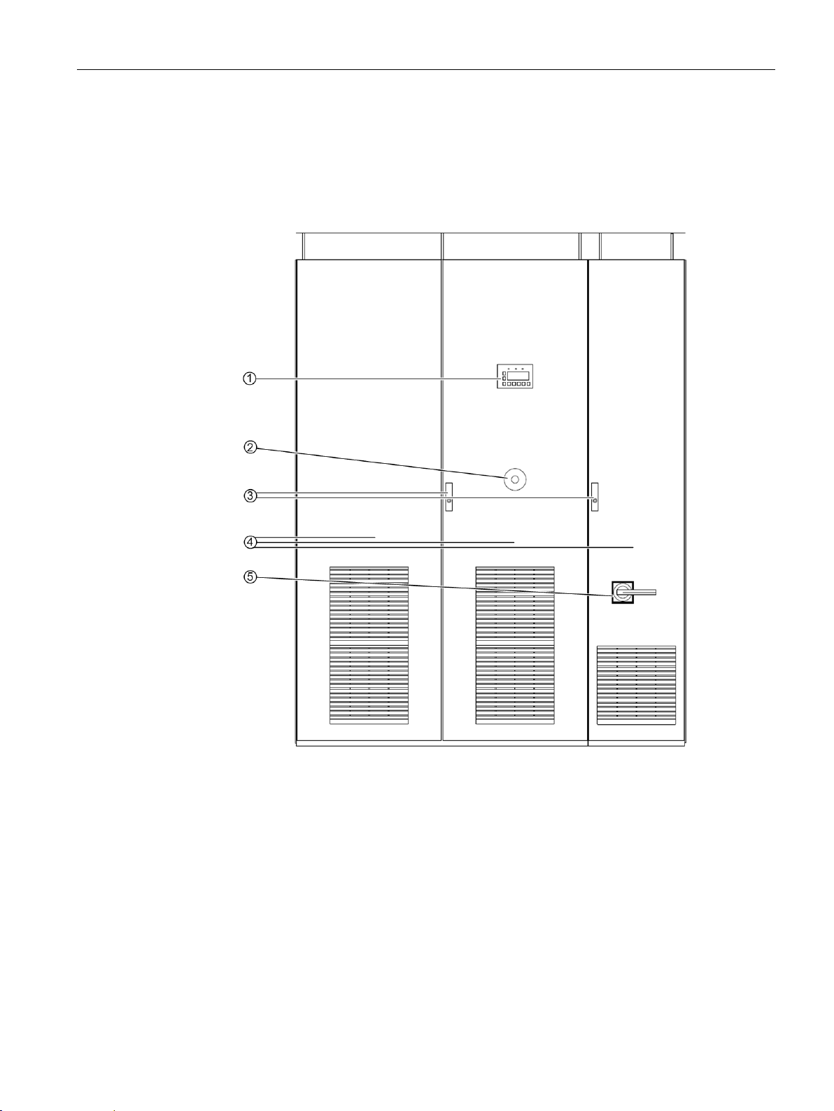
①
nect the inverter from the line voltage.
②
age-free immediately.
③
Danger due to hazardous voltages when the cabinet doors are open.
①
the inverter can continue to rotate after the unit has been switched off.
⑤
start up automatically when the line voltage is connected.
2.3 Areas that are potentially and particularly hazardous
Certain areas in the inverter can represent a hazard during operation. The diagram highlights
these areas that represent a potential hazard.
Observe the following safety notices and comply with all rules and instructions.
Stopping the inverter via the display or by means of external control devices does not discon-
When you press the EMERGENCY OFF button, this does not mean that the converter is volt-
These voltages can remain due to self-excitation if the connection to the motor is not removed.
Some surfaces in the inverter are hot during operation and for some time afterwards. Fans in
After disconnection of the line voltage, hazardous voltages can persist in the DC link (with
current-source DC link converters: in the commutation capacitors) or from external or auxiliary
power sources after the converter has been disconnected from the line voltage.
Depending on parameter settings and connection of external control devices, the inverter can
Figure 2-1 Areas that are potentially and particularly hazardous
Installation and Operating Instructions SINAMICS G180
Operating Instructions, 02/2019, 4BS0751-007
15
Safety information
WARNING
Live components
WARNING
Automatic startup
2.4
Notes for operator protection
Specialist personnel
qualified, trained staff.
2.4 Notes for operator protection
During operation and shortly after the system has been switched off with the EMERGENCY
OFF button, high voltages are still present in the converter and its components. These
voltages may remain if the connection to the motor is not removed or grounded. This
danger exists with permanent-magnet synchronous motors and synchronous motors which
are not de-excited immediately. These voltages may remain if the connection to the motor
is not removed or grounded. High voltages cause death or serious injury if the safety
instructions are not observed or if the equipment is handled improperly.
Never open the covers or doors when the system is in operation or while the DC link
capacitors are still discharging (in the case of current-source DC link inverters:
commutation capacitors). The DC link capacitors (commutation capacitors) can take up to
10 minutes to discharge (or 5 minutes with compact devices) after the EMERGENCY OFF
button is actuated.
Depending on parameter settings and connection of external control devices, the inverter
can start up automatically when the line voltage is connected. This can result in death,
serious injury or material damage.
Confirm whether or not your system is capable of automatic starting and, if appropriate,
take measures to ensure personal safety and operational readiness at the driven machine.
Read the following information about personal protection.
The device complies with the safety requirements according to EN 61800-5-1 and UL 508 C.
Ensure that any transport, installation, operation or maintenance work is carried out by
accordance with EN 50110 "Operation of electrical systems".
For the purpose of these basic safety instructions, "skilled technical personnel" means
people who are familiar with the installation, mounting, commissioning and operation of the
product. They must be properly qualified for the tasks with which they are charged. Qualified
personnel must also be thoroughly familiar with all the safety-related instructions and
measures described in the product documentation.
The minimum qualification must be that of an electrician in
Installation and Operating Instructions SINAMICS G180
16 Operating Instructions, 02/2019, 4BS0751-007
Safety information
Safety-relevant information for working on the inverter
DANGER
Live, moving or rotating parts
DANGER
High voltages
DANGER
Auxiliary and external supply systems
DANGER
Electric shock
2.4 Notes for operator protection
Inverters have live, moving or rotating parts.
Death or serious injury can result if any essential covers are removed without authorization
or in the case of improper use or incorrect installation or operation.
Always take all the necessary precautions before working on the device.
High voltages cause death or serious injury if the safety instructions are not observed or if
the equipment is handled improperly.
Voltages of more than 50 V are present when this unit is operational. These voltages may
remain for some time after switching off or as long as the motor is turning over.
Make sure that work is only carried out by qualified personnel under due observance of the
five safety rules, the information in these operating instructions, and the instructions on the
product itself.
Hazardous voltages (e.g. control voltage, signal voltage, supply voltage for heaters and
fans) can persist even after the inverter has been switched off. Contact with live parts can
result in death or serious injury.
Make sure that work is only carried out by qualified personnel under due observance of the
five safety rules, the information in these operating instructions, and the instructions on the
product itself.
If you carry out servicing work on the inverter without safely disconnecting the power
supply, serious injury or death due to electric shock can occur. The PTC input is not an
Emergency Off input which safely disconnects the inverter or the motor from the line
supply.
Safely and reliably disconnect the power supply before opening covers or terminal boxes at
the inverter. For example, use a main switch.
Installation and Operating Instructions SINAMICS G180
Operating Instructions, 02/2019, 4BS0751-007
17
Safety information
DANGER
High voltages
DANGER
DC link capacitor discharge time
2.4 Notes for operator protection
Electrical accidents including electric shock occur when general safety instructions for
working on the device are not observed. Death, serious injury or material damage will
result.
Please note the following information for your safety:
• Always observe the five safety rules whenever you are carrying out any work on the
device.
• Always disconnect the equipment before working on it.
• Leave the covers in place during normal operation and keep the cabinet doors closed.
• Do not use any instrumentation if you know it is defective or damaged.
• Secure the main circuit breaker in the OFF position so that it cannot be reconnected, for
example by removing the switch unit when working on a connected motor or the feeder
cable to the motor.
• Ground the inverter cabinet and chassis units properly to ensure that no accessible
parts of the equipment are energized or connected in any way to a dangerous voltage
source.
• Use an earthing spider for grounding purposes. Read the information provided in the
section "Safety instructions regarding maintenance and repairs" in "Maintenance and
servicing" in your operating instructions.
• Wear personnel protective gear such as goggles, ear protection and helmet to protect
yourself against injury.
• Always follow the national regulations and local specifications when working on the
equipment.
After the mains power has been switched off, high voltages still persist in the DC link
capacitors.
These cause death or serious injury if the safety instructions are not observed or if the
equipment is handled incorrectly.
The DC link capacitors require up to 10 minutes (5 minutes for compact units) before they
are discharged to a safe value (< 60 V).
After you have switched off the main power supply, do not touch the device or carry out any
maintenance work or repair work until the discharge time of 10 minutes (5 minutes for
compact devices) have elapsed.
Measure the voltage once the discharge time has elapsed.
Installation and Operating Instructions SINAMICS G180
18 Operating Instructions, 02/2019, 4BS0751-007
Safety information
CAUTION
Hot surfaces
2.5
Notes on liquid cooling
Follow the safety instructions for liquid-cooled converters.
WARNING
Electric shock as a result of defective cooling liquid system
2.5 Notes on liquid cooling
Certain components (e.g. the heat sink or filter reactor) can become very hot during
operation. These components can remain hot for a long time after operation.
The anti-condensation heating (optional) is switched on when the inverter is not operating
and the limit value set for the temperature control is reached. Once activated, the anticondensation heating can generate a great deal of heat.
Contact with hot surfaces can cause injuries (such as burns to the skin).
Never touch hot components just after you have switched off the inverter. Always take the
appropriate precautions before touching any components.
Short circuits can develop in electrical installations when liquid escapes from cooling
circuits. This can result in death, serious injury or material damage.
• Note the technical data of the liquid cooling system. You will find this data in Chapter
"Technical data of direct liquid cooling system" (Page 204) - and the technical data
sheet.
• Note the information in section "Permissible substance values for the cooling water"
(Page 205).
• Note the information in section "Liquid cooling" (Page 66).
• Protect the cooling liquid circuits against excess pressure, e.g. by installing a relief
valve.
• Make sure that the pipework installation and pressure testing procedures comply with
local safety regulations and national safety guidelines.
Installation and Operating Instructions SINAMICS G180
Operating Instructions, 02/2019, 4BS0751-007
19
Safety information
2.6
Safety precautions when handling anti-freeze
CAUTION
Physical injury caused by burns or poisoning is possible
NOTICE
Leaking antifreeze has a corrosive effect and may cause short-circuits.
Whenever you disconnect a connection in the cooling circuit, cover lower areas. Thoroughly
NOTICE
Impurities in the cooling circuit can cause converter modules to fail
2.6 Safety precautions when handling anti-freeze
Antifreeze is harmful to health. Inhalation or swallowing can lead to burns or poisoning.
Observe the following health and safety precautions when handling antifreeze:
• Do not inhale vapors.
• Keep the antifreeze away from food and beverages.
• Wear protective gloves and safety goggles.
• Avoid contact with skin and eyes.
When a connection is disconnected in the cooling circuit, antifreeze can escape and drip
down onto lower areas. These areas can corrode and therefore cause short-circuits.
remove antifreeze from areas that it has come into contact with and clean. Completely
remove all residues.
When carrying out any work on the cooling circuit, ensure that no impurities (e.g. dust,
sand, fluff, chips, etc.) are able to enter the cooling circuit. Make sure that all containers
and hoses, with which you handle the antifreeze are clean and are exclusively used for the
antifreeze.
Installation and Operating Instructions SINAMICS G180
20 Operating Instructions, 02/2019, 4BS0751-007

Safety information
First aid measures
Event
Measure
Wetted clothing
Remove clothing immediately.
advice.
ing. In any case, consult a doctor.
2.7
Standards and guidelines for proper use of inverters
Inverters are components which are intended for installation in electrical systems or machines.
2.7 Standards and guidelines for proper use of inverters
The following table lists the first aid measures:
Table 2- 1 Antifreeze: First aid measures
Skin contact Wash off immediately with plenty of water.
Eye contact Rinse thoroughly and immediately with plenty of water and seek medical
If swallowed If the affected person is completely conscious, immediately induce vomit-
In addition, observe the provisions of the EC safety data sheet in accordance with
91/155/EEC, as well as the generally applicable first aid rules.
Commissioning of the inverters is prohibited until one of the following two conditions is
verifiably fulfilled.
● The machine complies with the requirements of the following directives:
– Machinery directive 2006/42/EG
– EMC directive 2014/30/EG
● The electrical installation complies with the requirements of the following directives:
– Low-voltage directive 2014/35/EG
– EMC directive
The inverters comply with the requirements of the low-voltage directive 2014/35/EG and the
EMC directive 2014/30/EG.
To ensure that this equipment functions perfectly and safely, observe the following:
● Transportation in accordance with proper procedures
● Proper storage
● Proper installation and assembly
● Careful operation
● Careful maintenance
Installation and Operating Instructions SINAMICS G180
Operating Instructions, 02/2019, 4BS0751-007
The unit must only be used for the applications specified in the catalog and only in
conjunction with devices and components recommended and approved by Siemens.
21
Safety information
Note
Familiarize yourself with the local safety requirements and national safety guidelines and
always observe them.
2.8
Plant safety
DANGER
Unsecured installation site
Procedure
2.8 Plant safety
Read the following information about safeguarding the equipment.
This inverter is intended for use in industrial power installations and machines.
Accidents can occur if the equipment is not used for the intended purpose, is incorrectly
operated, is inadequately maintained or can be accessed by unauthorized persons. Death,
serious injury or material damage will result.
Secure the installation site against unauthorized access when using the inverter outside
industrial areas using suitable equipment (e.g. safety fences) and corresponding signage.
Install the inverter in a suitable area to which only properly trained personnel have access.
You are responsible for the safety of the system.
You must ensure that the following requirements are fulfilled:
● Basic planning and all the work involved in transporting, assembling, installing,
commissioning, maintaining and repairing the equipment is only carried out by qualified
personnel or personnel supervised by responsible skilled technicians.
● The operating instructions and the complete product documentation are always available
when carrying out any work.
● The technical data and specifications regarding the permissible installation, connection,
environmental, and operating conditions are observed consistently.
● The system-specific installation and safety regulations are observed and measures are
taken to ensure personal safety.
● It is prohibited for unqualified persons to work on these devices or in their vicinity.
The product documentation, especially the operating instructions, and the notices on the unit
itself therefore contain only the information required by qualified personnel to use the
installations or machines for their intended purpose.
Installation and Operating Instructions SINAMICS G180
22 Operating Instructions, 02/2019, 4BS0751-007

Safety information
Note
Siemens Service Centers
The services and support provided by the Siemens service centers are recommended for
planning, installation, commissioning, and servicing work.
Note
Engineering information
Systems in which
safety devices in order to comply with safety requirements (e.g. equipment and product
safety law, accident prevention regulations).
2.9
Security information
2.9 Security information
the inverters are installed must be fitted with additional monitoring and
Siemens provides products and solutions with industrial security functions that support the
secure operation of plants, systems, machines and networks.
In order to protect plants, systems, machines and networks against cyber threats, it is
necessary to implement – and continuously maintain – a holistic, state-of-the-art industrial
security concept. Siemens’ products and solutions constitute one element of such a concept.
Customers are responsible for preventing unauthorized access to their plants, systems,
machines and networks. Such systems, machines and components should only be
connected to an enterprise network or the internet if and to the extent such a connection is
necessary and only when appropriate security measures (e.g. firewalls and/or network
segmentation) are in place.
For additional information on industrial security measures that may be implemented, please
visit
https://www.siemens.com/industrialsecurity.
Siemens’ products and solutions undergo continuous development to make them more
secure. Siemens strongly recommends that product updates are applied as soon as they are
available and that the latest product versions are used. Use of product versions that are no
longer supported, and failure to apply the latest updates may increase customer’s exposure
to cyber threats.
To stay informed about product updates, subscribe to the Siemens Industrial Security RSS
Feed under
https://www.siemens.com/industrialsecurity.
Installation and Operating Instructions SINAMICS G180
Operating Instructions, 02/2019, 4BS0751-007
23
Safety information
WARNING
Unsafe operating states resulting from software manipulation
WARNING
Malfunctions of the machine as a result of incorrect or changed parameter settings
2.10
Components that can be destroyed by electrostatic discharge (ESD)
ESD guidelines
Material damage caused by electrostatic discharge.
2.10 Components that can be destroyed by electrostatic discharge (ESD)
Software manipulations (e.g. viruses, trojans, malware or worms) can cause unsafe
operating states in your system that may lead to death, serious injury, and property
damage.
• Keep the software up to date.
• Incorporate the automation and drive components into a holistic, state-of-the-art
industrial security concept for the installation or machine.
• Make sure that you include all installed products into the holistic industrial security
concept.
• Protect files stored on exchangeable storage media from malicious software by with
suitable protection measures, e.g. virus scanners.
As a result of incorrect or changed parameterization, machines can malfunction, which in
turn can lead to injuries or death.
• Protect the parameterization (parameter assignments) against unauthorized access.
• Handle possible malfunctions by taking suitable measures, e.g. emergency stop or
emergency off.
Electronic components can be destroyed in the event of improper handling, transport,
storage, and shipping.
Pack the electronic components in appropriate ESD packaging; e.g. ESD foam, ESD
packaging bags and ESD transport containers.
Installation and Operating Instructions SINAMICS G180
24 Operating Instructions, 02/2019, 4BS0751-007
Safety information
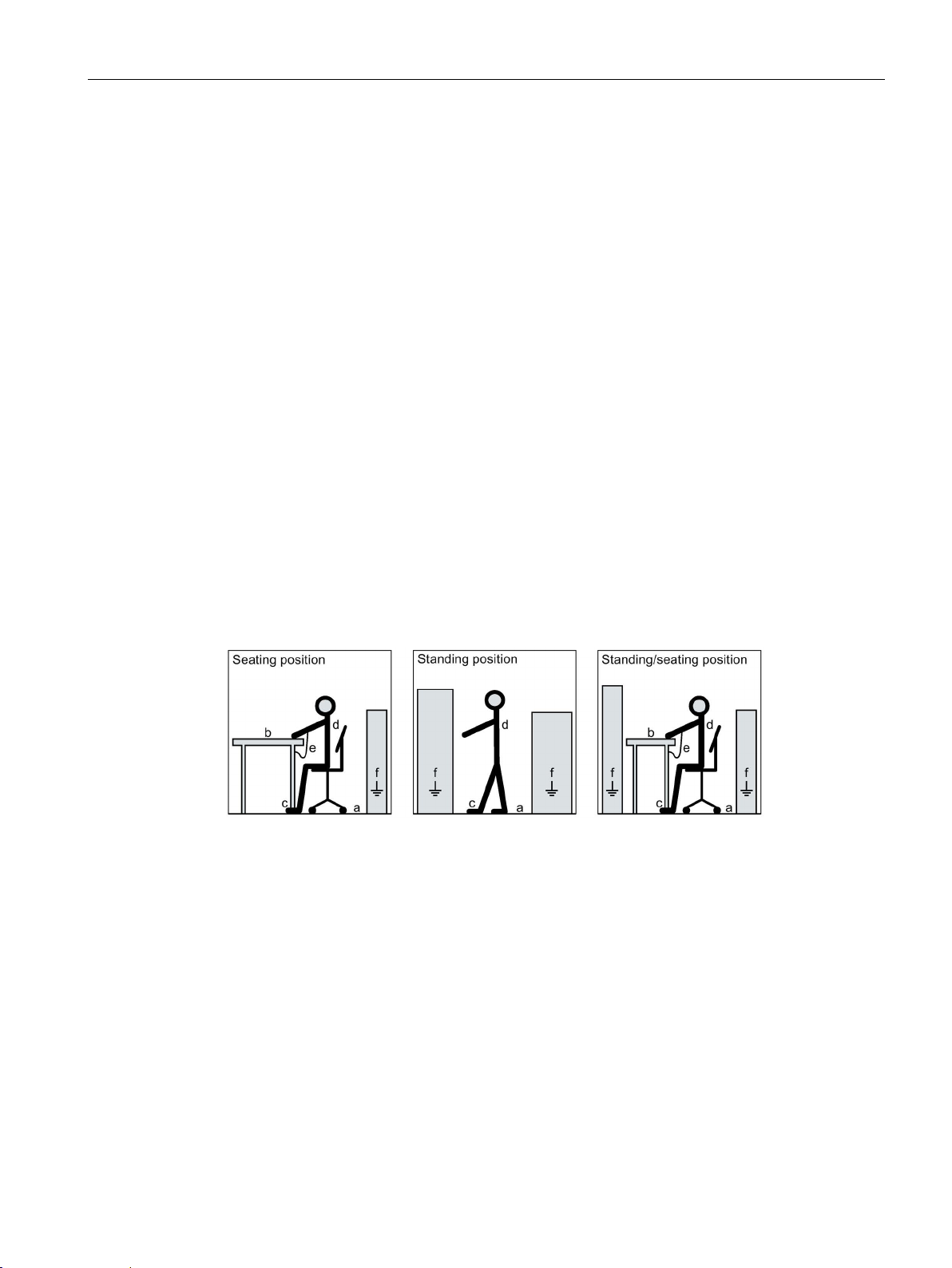
a =
Conductive floor covering 1)
b =
ESD furniture
c =
ESD shoes or ESD shoe grounding strips 2)
d =
ESD clothing
e =
ESD wrist strap
f =
Cabinet ground connection
Only effective in conjunction with ESD shoes or ESD shoe grounding strips
Only effective in conjunction with conductive floor covering
2.10 Components that can be destroyed by electrostatic discharge (ESD)
To protect your equipment against damage, follow the instructions given below.
● Avoid physical contact with electronic components. If it is essential that you perform work
on these components, you must wear one of the following pieces of protective gear:
– Grounded ESD wrist strap
– ESD shoes or ESD shoe grounding strips if there is also an ESD floor.
● Do not place electronic components close to data terminals, monitors or televisions.
Maintain a minimum clearance to the screen (> 10 cm).
● Electronic components should not be brought into contact with electrically insulating
materials such as plastic foil, plastic parts, insulating table supports or clothing made of
synthetic fibers.
● Bring components into contact only with ESD-compliant materials, e.g. ESD tables, ESD
surfaces, ESD packaging.
● Only carry out measurements on the components if one of the following conditions is met:
– The measuring device is grounded with a protective conductor, for example.
– The measuring head of a floating measuring device has been discharged directly
before the measurement.
The necessary ESD protective measures for the entire working range for electrostatically
sensitive devices are illustrated once again in the following drawings.
Precise instructions for ESD protective measures are specified in the standard
DIN EN 61340-5-1.
1)
2)
Figure 2-2 ESD information
Installation and Operating Instructions SINAMICS G180
Operating Instructions, 02/2019, 4BS0751-007
25

Safety information
2.11
Electromagnetic fields
WARNING
Electromagnetic fields "electro smog"
2.11 Electromagnetic fields
Electromagnetic fields are produced during operation of electrical energy technology
systems, e.g. transformers, inverters, motors etc.
Electromagnetic fields can interfere with electronic devices, which could cause them to
malfunction. For example, the operation of heart pacemakers can be impaired, potentially
leading to damage to a person's health or even death. It is therefore forbidden for persons
with heart pacemakers to enter these areas.
The plant operator is responsible for taking appropriate measures (labels and hazard
warnings) to adequately protect operating personnel and others against any possible risk.
● Observe the relevant nationally applicable health and safety regulations. In Germany,
"electromagnetic fields" are subject to regulations BGV B11 and BGR B11 stipulated by
the German statutory industrial accident insurance institution.
● Display adequate hazard warning notices.
● Place barriers around hazardous areas.
● Take measures, e.g. using shields, to reduce electromagnetic fields at their source.
● Make sure that personnel are wearing the appropriate protective gear.
Installation and Operating Instructions SINAMICS G180
26 Operating Instructions, 02/2019, 4BS0751-007
Safety information
2.12
Radio telephones and mobile telephones
Safety instructions
CAUTION
Radio telephones
to equipment of the type specified below can occur and possibly result in physical injuries to
CAUTION
Mobile telephones
2.12 Radio telephones and mobile telephones
If you use radio communication equipment > 2 W in close proximity to the inverter, damage
personnel:
• Missing pulses during inverter operation can occur.
• Defects of the power elements can occur.
• The inverter can shut down.
• Contactors can chatter.
• Interference on binary outputs.
Do not use radio telephones > 2 W in close proximity to the device.
Radio telephones with lower outputs must not be used at a distance of less than 1 m from
the inverter.
The use of mobile telephones near the inverter when it is in operation can result in the
generation of erroneous pulses and possibly give rise to physical injuries to personnel.
Switch off mobile telephones when you are near the device.
Installation and Operating Instructions SINAMICS G180
Operating Instructions, 02/2019, 4BS0751-007
27
Safety information
2.13
Note regarding fiber-optic cables
CAUTION
Erroneous pulses in fiber-optic cables
2.14
Protecting/fusing the external 230 V AC control voltage
WARNING
External control voltage without fuse protection
2.13 Note regarding fiber-optic cables
Fiber-optic cable systems are deployed in some inverters. Please observe the following
warning.
Figure 2-3 Photography prohibited
Erroneous pulses in fiber-optic cables caused by camera flash lights can result in
malfunction and damage to the inverter and motor and potentially result in injury to
personnel.
It is not permissible to photograph inverters with fiber-optic cable systems using a camera
flash light when they are in operation! Only photograph these types of inverters when they
are in a no-voltage state.
If you use an external control voltage without suitable protection (e.g. fuses), then
overloads and short-circuits can occur. This can result in death, serious injury or material
damage.
The device may only be operated with a protected external control voltage. Note the
following recommendation.
Install one of the following options to protect the external control voltage:
● Miniature fuse in accordance with EN 60127: 2 A … 6 A, slow, maximum 150 VA
● Miniature circuit-breaker: 2 A … 6 A, characteristic D, maximum 150 VA
Installation and Operating Instructions SINAMICS G180
28 Operating Instructions, 02/2019, 4BS0751-007
 Loading...