

Siemens SINAMICS G130, SINAMICS G150, SINAMICS S120, SINAMICS S150 Engineering Manual
s
© Siemens AG 2015
SINAMICS - Low Voltage
Engineering Manual
SINAMICS G130, G150, S120 Chassis, S120 Cabinet Modules, S150
Supplement to Catalogs D 11 and D 21.3
SINAMICS Drives
Version Edition
6.4 November
2015

Literary reference
The following title by Jens Weidauer, Richard Messer
Electrical Drives
Principles • Planning • Applications • Solutions
offers a wide-ranging, clear and comprehensible overview of modern drive systems.
The book covers all aspects of modern electrical drive systems from the viewpoint of the user. On the one hand, it is
aimed at practicians who want to understand, design, use and maintain electrical
drives. On the other, it will be a useful reference document for skilled workers,
technicians, engineers and students who wish to gain a broad general
understanding of electrical drive technology. The author explains the
fundamentals of electrical drives and their design, and goes on to describe
different applications as well as complex automation solutions. He presents the
entire spectrum of drive solutions with the relevant core applications in each
case. He gives special attention to the practice of combining multiple drives into
drive systems and to the integration of drives into automated systems.
In simple, plain language and illustrated by numerous graphics, complex
relationships are explained in a clear and coherent manner. The author
consciously avoids the use of complicated mathematical formulae, concentrating
instead on providing plain, comprehensible explanations of operating principles
and relationships. The book is designed to help readers to understand electrical
drive systems in their entirety and to solve the drive-related problems they may
encounter in their daily working lives.
Contents
1 Overview
2 Mechanical principles
3 Electrical principles
4 Fixed-speed and variable-speed drives with direct current motor
5 Fixed-speed and variable-speed drives with asynchronous motor
6 Servo drives
7 Stepper drives
8 Electrical drives at a glance
9 Fieldbuses for electrical drives
10 Process control with electrical drives
11 Motion control
12 EMC and electrical drives
13 Planning electrical drives
14 Troubleshooting on electrical drives
Print ISBN: 978-3-89578-434-7
ePDF ISBN: 978-3-89578-923-6
1st Edition 2014
Published by: Siemens Aktiengesellschaft, Berlin and Munich
Publishing house: Publicis Publishing, Erlangen
www.publicis-books.de

s
Foreword
List of Contents
SINAMICS Low Voltage
Engineering Manual
Version 6.4 – November 2015
Supplement to Catalogs D 11 and D 21.3
Fundamental Principles and System Description
EMC Installation Guideline
General Engineering Information for SINAMICS
Converter Chassis Units
SINAMICS G130
Converter Cabinet Units
SINAMICS G150
General Information about Built-in and Cabinet Units
SINAMICS S120
Disclaimer
We have checked that the contents of this document
correspond to the hardware and software described.
However, as deviations cannot be totally excluded, we are
unable to guarantee complete consistency. The information
given in this publication is reviewed at regular intervals and
any corrections that might be necessary are made in the
subsequent editions.
Subject to change without prior notice.
ã Siemens AG 2015
General Information about Modular Cabinet Units
SINAMICS S120 Cabinet Modules
Converter Cabinet Units
SINAMICS S150
Description of Options for Cabinet Units
SINAMICS G150, S120 Cabinet Modules, S150
General Information about Drive Dimensioning
Motors
SINAMICS Engineering Manual – November 2015
Ó Siemens AG
3/528

Foreword
Engineering Information
To all SINAMICS customers!
This engineering manual is supplementary to the SINAMICS Catalogs D 11 and D 21.3 and is designed to provide
additional support to users of SINAMICS converters. It focuses on drives with units in Chassis and Cabinet format in
the output power range ≥ 75 KW and operating in vector control mode (drive objects of vector type).
All information in this engineering manual refers to device variants equipped with the following hardware and
software:
· Power unit with Control Interface Module CIM (order number ending in 3, e.g. 6SL3310-1GE38-4AA3)
· CU320-2 Control Unit
· Firmware version 4.3 or higher
The engineering manual contains a general analysis of the fundamental principles of variable-speed drives as well as
detailed system descriptions and specific information about the following units in the SINAMICS equipment range:
· Converter Chassis Units SINAMICS G130 (Catalog D 11)
· Converter Cabinet Units SINAMICS G150 (Catalog D 11)
· Modular Chassis Units SINAMICS S120 (Catalogs D 21.3
and PM 21 / "SINAMICS S120 drive system")
· Modular Cabinet Units SINAMICS S120 Cabinet Modules (Catalog D 21.3)
· Converter Cabinet Units SINAMICS S150 (Catalog D 21.3)
This engineering manual is divided into different chapters.
The first chapter "Fundamental Principles and System Description" focuses on the physical fundamentals of electrical
variable-speed three-phase AC drives and provides general system descriptions of products in the SINAMICS range.
The second chapter “EMC Installation Guideline” gives an introduction to the subject of Electromagnetic Compatibility
(EMC), and provides all information required to engineer and install drives with the aforementioned SINAMICS
devices in an EMC-compliant manner.
The following chapters, which describe how to engineer SINAMICS G130, G150, S120 Built-in units, S120 Cabinet
Modules and S150, focus on subjects relating to specific units in more detail than the general system descriptions.
This engineering manual can and should only be viewed as a supplement to catalogs D 11, D 21.3 and PM 21 /
"SINAMICS S120 drive system". The document does not therefore contain any ordering data. The manual is
available only in electronic form in German or English.
The information of this manual is aimed at technically qualified and trained personnel. The configuring engineer is
responsible for assessing whether the information provided is sufficiently comprehensive for the application in
question and, therefore, assumes overall responsibility for the whole drive or the whole system.
The information provided in this engineering manual contains descriptions or characteristics of performance which in
case of actual use do not always apply as described, or which may change as a result of further development of the
products.
The desired performance characteristics are firmly binding only if expressly agreed upon in the contract.
Availability and technical specifications are subject to change without prior notice.
EMC warning information
The SINAMICS converter systems G130, G150, S120 Chassis units, S120 Cabinet Modules and S150 are not
designed to be connected to public networks (first environment). RFI suppression of these converter systems is
designed for industrial networks (second environment) in accordance with the EMC product standard EN 61800-3 for
variable-speed drives. If the converter systems are connected to public networks (first environment) electromagnetic
interference can occur. With additional measures (e.g. EMC-filters) the converter systems can also be connected to
public networks
4/528
SINAMICS Engineering Manual – November 2015
Ó Siemens AG

Foreword
Engineering Information
Overview of the most significant additions and modifications as compared
to Version 6.3 of this engineering manual
1.1.3.2 Interrelationships between current controller clock cycle, pulse frequency
and output frequency
à This section has been updated owing to the introduction of stricter export regulations for frequency
converters as a result of which the maximum output frequency in the standard firmware has been
limited to 550 Hz for all the converters described in this manual since January 1, 2015 (firmware
versions ≥ 4.7 HF7).
With the license "High output frequency" (6SL3074-0AA02-0AA0) for SINAMICS S (which can also be
ordered as option J01 for the SINAMICS S CompactFlash card), it is now possible to increase the
maximum possible output frequency f
standard firmware, however, the license "High output frequency" is subject to export restrictions.
1.2.6 Connection of converters to non-grounded systems (IT)
à Information about the new VSM10 Voltage Sensing Module has been added to this section. The
jumper in connector X530 of the new VSM10 must be removed in IT systems if a very high insulation
resistance in excess of 10 MΩ is required.
1.6 SINAMICS Infeeds and their properties
à An urgent notice regarding correct control of the precharging contactor and the bypass contactor
has been added to this section.
1.16 Liquid-cooled SINAMICS S120 units
à This section has been updated. The recommendation regarding use of the inhibitor NALCO®
TRAC100 (formerly NALCO® 00GE056) has been removed. Furthermore, the charts that specify the
pressure drop across the heat sink of the SINAMICS S120 Chassis unit as a function of the
volumetric flow rate for various recommended anti-freezes have also been revised.
3.6.6 Prevention of condensation in equipment cooled by air conditioners and climate control
systems
à More specific information has been added to the last two paragraphs in this section. It now
includes recommendations regarding the setpoint temperature setting and the switching hysteresis of
the two-step controller as a function of the maximum predicted air humidity.
6.5 Precharging of the DC link and precharging currents
à An urgent notice regarding the correct phase sequence and correct control of the precharging
contactor and the bypass contactor has been added to this section.
7 General Information about Modular Cabinet Units SINAMICS S120 Cabinet Modules
à A description of the new liquid-cooled SINAMICS S120 Cabinet Modules has been added to this
chapter. The chapter is now structured as follows:
7.1 General (valid for air-cooled and liquid-cooled SINAMICS S120 Cabinet Modules)
7.2 Air-cooled SINAMICS S120 Cabinet Modules (revised)
7.3 Liquid-cooled SINAMICS S120 Cabinet Modules (new):
Description of the liquid-cooled S120 Cabinet Modules, dimensioning information,
Description of the cooling circuit, cooling circuit engineering.
– New liquid-cooled S120 Motor Modules in Chassis format
à The technical data of the new liquid-cooled S120 Motor Modules in Chassis format (400 kW /
400 V / 745 A and 450 kW / 690 V / 465 A) have been incorporated in all the relevant tables.
‒ Corrections
àSpelling and formatting errors have been corrected.
for SINAMICS S to 650 Hz again. By contrast with the
out max
SINAMICS Engineering Manual – November 2015
Ó Siemens AG
5/528

List of Contents
Engineering Information
List of Contents
1 Fundamental Principles and System Description .......................................................................... 16
1.1 Operating principle of SINAMICS converters .............................................................................................. 16
1.1.1 General operating principle ............................................................................................................ 16
1.1.2 Pulse modulation method ............................................................................................................... 16
1.1.2.1 Generation of a variable voltage by pulse-width modulation ............................................................. 17
1.1.2.2 Maximum attainable output voltage with space vector modulation SVM ........................................... 18
1.1.2.3 Maximum attainable output voltage with pulse-edge modulation PEM .............................................. 19
1.1.3 The pulse frequency and its influence on key system properties ...................................................... 21
1.1.3.1 Factory settings and ranges of pulse frequency settings .................................................................. 21
1.1.3.2 Interrelationships between current controller clock cycle, pulse frequency and output frequency ....... 22
1.1.3.3 Influence of the pulse frequency on the inverter output current ........................................................ 24
1.1.3.4 Influence of the pulse frequency on losses and efficiency of inverter and motor................................ 24
1.1.3.5 Influence of the pulse frequency on the motor noise ........................................................................ 24
1.1.3.6 Correlation between pulse frequency and motor-side options .......................................................... 26
1.1.4 Open-loop and closed-loop control modes ...................................................................................... 27
1.1.4.1 General information about speed adjustment .................................................................................. 27
1.1.4.2 V/f control modes ........................................................................................................................... 27
1.1.4.3 Field-oriented control modes .......................................................................................................... 29
1.1.4.4 A comparison of the key features of open-loop and closed-loop control modes ................................ 31
1.1.4.5 Load balance on mechanically coupled drives................................................................................. 31
1.1.5 Power ratings of SINAMICS converters and inverters / Definition of the output power ....................... 33
1.2 Supply systems and supply system types .................................................................................................. 35
1.2.1 General ......................................................................................................................................... 35
1.2.2 Connection of converters to the supply system and protection of converters .................................... 37
1.2.3 Short Circuit Current Rating (SCCR according to UL) ...................................................................... 38
1.2.4 Maximum short-circuit currents (SCCR according to IEC) and minimum short-circuit currents ..................... 39
1.2.5 Connection of converters to grounded systems (TN or TT) .............................................................. 44
1.2.6 Connection of converters to non-grounded systems (IT) .................................................................. 45
1.2.7 Connection of converters to supply systems with different short-circuit powers ................................. 49
1.2.8 Supply voltage variations and supply voltage dips ........................................................................... 51
1.2.9 Behaviour of SINAMICS converters during supply voltage variations and dips ................................. 52
1.2.10 Permissible harmonics on the supply voltage .................................................................................. 59
1.2.11 Summary of permissible supply system conditions for SINAMICS converters ................................... 60
1.2.12 Line-side contactors and circuit breakers ........................................................................................ 61
1.3 Transformers ............................................................................................................................................... 66
1.3.1 Unit transformers ........................................................................................................................... 66
1.3.1.1 General information about calculating the required apparent power of a unit transformer .................. 66
1.3.1.2 Method of calculating the required apparent power S of a unit transformer ....................................... 68
1.3.2 Transformer types .......................................................................................................................... 69
1.3.3 Features of standard transformers and converter transformers ........................................................ 70
1.3.4 Three-winding transformers ............................................................................................................ 71
1.4 Harmonic effects on the supply system ...................................................................................................... 72
1.4.1 General ......................................................................................................................................... 72
1.4.2 Harmonic currents of 6-pulse rectifier circuits .................................................................................. 74
1.4.2.1 SINAMICS G130, G150, S120 Basic Infeed and S120 Smart Infeed in motor operation ................... 74
1.4.2.2 SINAMICS S120 Smart Infeed in regenerative operation ................................................................. 76
1.4.3 Harmonic currents of 6-pulse rectifier circuits with Line Harmonics Filter .......................................... 77
6/528
SINAMICS Engineering Manual – November 2015
Ó Siemens AG

List of Contents
Engineering Information
1.4.4 Harmonic currents of 12-pulse rectifier circuits .................................................................................79
1.4.5 Harmonic currents and harmonic voltages of Active Infeeds (AFE technology)..................................80
1.4.6 Standards and permissible harmonics .............................................................................................82
1.5 Line-side reactors and filters .......................................................................................................................86
1.5.1 Line reactors (line commutating reactors) ........................................................................................86
1.5.2 Line Harmonics Filters (LHF and LHF compact)...............................................................................87
1.5.2.1 Operating principle of Line Harmonics Filters (LHF and LHF compact) .............................................87
1.5.2.2 Line Harmonics Filter (LHF) with separate housing (6SL3000-0J_ _ _-_AA0) ...................................88
1.5.2.3 Line Harmonics Filter compact (LHF compact) as Option L01 for SINAMICS G150 ...........................90
1.5.3 Line filters (radio frequency interference (RFI) suppression filter or EMC filter) .................................92
1.5.3.1 General information and standards..................................................................................................92
1.5.3.2 Line filters for the "first" environment (residential) and "second" environment (industrial) ..........................95
1.5.3.3 Operating principle of line filters ......................................................................................................95
1.5.3.4 Magnitude of leakage or interference currents .................................................................................96
1.5.3.5 EMC-compliant installation ..............................................................................................................97
1.6 SINAMICS Infeeds and their properties ...................................................................................................... 100
1.6.1 Basic Infeed ................................................................................................................................. 100
1.6.2 Smart Infeed ................................................................................................................................ 102
1.6.3 Active Infeed ................................................................................................................................ 105
1.6.4 Comparison of the properties of the different SINAMICS Infeeds .................................................... 110
1.6.5 – – – ............................................................................................................................................ 112
1.6.6 Redundant line supply concepts .................................................................................................... 112
1.6.7 Permissible total cable length for S120 Infeed Modules feeding multi-motor drives ......................... 117
1.7 SINAMICS braking units (Braking Modules and braking resistors) ........................................................... 118
1.8 SINAMICS Inverters or Motor Modules....................................................................................................... 119
1.8.1 Operating principle and properties ................................................................................................. 119
1.8.2 Drive configurations with multiple Motor Modules connected to a common DC busbar .................... 120
1.8.2.1 Connection of Motor Modules to the DC busbar, fuse protection and precharging ........................... 120
1.8.2.2 Arrangement of Motor Modules along the DC busbar ..................................................................... 122
1.8.2.3 Permissible dimensions and topologies of the DC busbar .............................................................. 125
1.8.2.4 Short-circuit currents on the DC busbar ......................................................................................... 127
1.8.2.5 Maximum power rating of drive configurations at a common DC busbar ......................................... 129
1.9 Effects of using fast-switching power components (IGBTs) ..................................................................... 131
1.9.1 Increased current load on the inverter output as a result of long motor cables ................................. 131
1.9.2 Special issues relating to motor-side contactors and circuit breakers .............................................. 133
1.9.3 Increased voltage stress on the motor winding as a result of long motor cables .............................. 134
1.9.4 Bearing currents caused by steep voltage edges on the motor ....................................................... 139
1.9.4.1 Measures for reducing bearing currents......................................................................................... 140
1.9.4.1.1 EMC-compliant installation for optimized equipotential bonding in the drive system ........................ 141
1.9.4.1.2 Insulated bearing at the non-drive end (NDE) of the motor ............................................................. 145
1.9.4.1.3 Other measures............................................................................................................................ 145
1.9.4.2 Summary of bearing current types and counter-measures .............................................................. 146
1.10 Motor-side reactors and filters ................................................................................................................. 148
1.10.1 Motor reactors .............................................................................................................................. 148
1.10.1.1 Reduction of the voltage rate-of-rise dv/dt at the motor terminals.................................................... 148
1.10.1.2 Reduction of additional current peaks when long motor cables are used......................................... 148
1.10.1.3 Permissible motor cable lengths with motor reactor(s) for single- and multi-motor drives ................. 149
1.10.1.4 Supplementary conditions which apply when motor reactors are used ............................................ 152
1.10.2 dv/dt filters plus VPL and dv/dt filters compact plus VPL ................................................................ 153
SINAMICS Engineering Manual – November 2015
Ó Siemens AG
7/528

List of Contents
Engineering Information
1.10.2.1 Design and operating principle ..................................................................................................... 153
1.10.2.2 Supplementary conditions which apply when dv/dt-filters are used ................................................ 154
1.10.3 Sine-wave filters .......................................................................................................................... 155
1.10.3.1 Design and operating principle ..................................................................................................... 155
1.10.3.2 Supplementary conditions which apply when sine-wave filters are used ......................................... 156
1.10.4 Comparison of the properties of the motor-side reactors and filters ................................................ 157
1.11 – – – .......................................................................................................................................................... 159
1.12 Power cycling capability of IGBT modules and inverter power units ..................................................... 159
1.12.1 General ....................................................................................................................................... 159
1.12.2 IGBT module with cyclically alternating current load ...................................................................... 159
1.12.3 Dimensioning of the power units for operation at low output frequencies ........................................ 160
1.13 Load duty cycles ...................................................................................................................................... 164
1.13.1 General ....................................................................................................................................... 164
1.13.2 Standard load duty cycles ............................................................................................................ 164
1.13.3 Free load duty cycles ................................................................................................................... 165
1.13.4 Thermal monitoring of the power unit ............................................................................................ 179
1.13.5 Operation of converters at increased pulse frequency ................................................................... 179
1.14 Efficiency of SINAMICS converters at full load and at partial load ......................................................... 183
1.14.1 Converter efficiency at full load ..................................................................................................... 183
1.14.2 Converter efficiency at partial load ................................................................................................ 184
1.14.2.1 – – – ............................................................................................................................................ 184
1.14.2.2 Partial load efficiency of S120 Basic Line Modules ........................................................................ 184
1.14.2.3 Partial load efficiency of S120 Smart Line Modules ....................................................................... 185
1.14.2.4 Partial load efficiency of S120 Active Line Modules + Active Interface Modules .............................. 185
1.14.2.5 Partial load efficiency of S120 Motor Modules ............................................................................... 186
1.14.2.6 Partial load efficiency of G130 / G150 converters .......................................................................... 187
1.14.2.7 Partial load efficiency of S150 converters ...................................................................................... 190
1.15 Parallel connections of converters .......................................................................................................... 193
1.15.1 General ....................................................................................................................................... 193
1.15.2 Parallel connections of SINAMICS converters ............................................................................... 193
1.15.3 Parallel connection of S120 Basic Line Modules ........................................................................... 195
1.15.4 Parallel connection of S120 Smart Line Modules ........................................................................... 197
1.15.5 Parallel connection of S120 Active Line Modules .......................................................................... 199
1.15.6 Parallel connection of S120 Motor Modules .................................................................................. 201
1.15.7 Admissible and inadmissible winding systems for parallel connections of converters ...................... 203
1.16 Liquid-cooled SINAMICS S120 units ........................................................................................................ 206
1.16.1 General ....................................................................................................................................... 206
1.16.2 Design of the liquid-cooled SINAMICS S120 units ......................................................................... 206
1.16.3 Cooling circuit and coolant requirements....................................................................................... 207
1.16.4 Example of a closed cooling circuit for liquid-cooled SINAMICS S120 units.................................... 210
1.16.5 Example of an open cooling circuit for liquid-cooled SINAMICS S120 units .................................... 210
1.16.6 Example of coolant temperature control for condensation prevention ............................................. 211
1.16.7 Information about cooling circuit configuration ............................................................................... 214
1.16.8 Information about cabinet design .................................................................................................. 223
8/528
SINAMICS Engineering Manual – November 2015
Ó Siemens AG

List of Contents
Engineering Information
2 EMC Installation Guideline ............................................................................................................227
2.1 Introduction ................................................................................................................................................ 227
2.1.1 General ........................................................................................................................................ 227
2.1.2 EC Directives ............................................................................................................................... 227
2.1.3 CE marking .................................................................................................................................. 227
2.1.4 EMC Directive .............................................................................................................................. 228
2.1.5 EMC product standard EN 61800-3 ............................................................................................... 228
2.2 Fundamental principles of EMC ................................................................................................................. 230
2.2.1 Definition of EMC ......................................................................................................................... 230
2.2.2 Interference emissions and interference immunity.......................................................................... 231
2.3 The frequency converter and its EMC ........................................................................................................ 231
2.3.1 The frequency converter as a source of interference ...................................................................... 231
2.3.2 The frequency converter as a high-frequency source of interference .............................................. 232
2.3.3 The frequency converter as a low-frequency source of interference ................................................ 236
2.3.4 The frequency converter as potentially susceptible equipment ....................................................... 237
2.3.4.1 Methods of influence..................................................................................................................... 237
2.3.4.1.1 Conductive coupling ..................................................................................................................... 237
2.3.4.1.2 Capacitive coupling ...................................................................................................................... 238
2.3.4.1.3 Inductive coupling ......................................................................................................................... 239
2.3.4.1.4 Electromagnetic coupling (radiative coupling) ................................................................................ 240
2.4 EMC-compliant installation ........................................................................................................................ 240
2.4.1 Zone concept within the converter cabinet ..................................................................................... 241
2.4.2 Converter cabinet structure ........................................................................................................... 242
2.4.3 Cables inside the converter cabinet ............................................................................................... 242
2.4.4 Cables outside the converter cabinet ............................................................................................. 243
2.4.5 Cable shields................................................................................................................................ 243
2.4.6 Equipotential bonding in the converter cabinet, in the drive system, and in the plant ....................... 243
2.4.7 Examples for installation ............................................................................................................... 245
2.4.7.1 EMC-compliant installation of a SINAMICS G150 converter cabinet unit ......................................... 245
2.4.7.2 EMC-compliant construction/installation of a cabinet with a SINAMICS G130 Chassis unit .............. 246
2.4.7.3 EMC-compliant cable routing on the plant side on cable racks and in cable ducts ........................... 247
3 General Engineering Information for SINAMICS...........................................................................249
3.1 Overview of documentation ....................................................................................................................... 249
3.2 Safety-integrated / Drive-integrated safety functions ................................................................................ 254
3.2.1 Safety Integrated Basic Functions Safe Torque Off (STO) und Safe Stop 1 (SS1)........................... 254
3.3 Precharging intervals of the DC link .......................................................................................................... 258
3.3.1 SINAMICS Booksize units ............................................................................................................. 258
3.3.2 SINAMICS Chassis units .............................................................................................................. 258
3.4 Operator Panels .......................................................................................................................................... 258
3.4.1 Basic Operator Panel (BOP20) ..................................................................................................... 258
3.4.2 Advanced Operator Panel (AOP30)............................................................................................... 258
3.5 CompactFlash Cards for CU320-2 Control Units ....................................................................................... 260
3.6 Cabinet design and air conditioning .......................................................................................................... 261
3.6.1 Directives and standards .............................................................................................................. 261
3.6.2 Physical fundamental principles .................................................................................................... 263
3.6.3 Cooling air requirements and air opening cross-sections in the cabinet .......................................... 265
3.6.4 Required ventilation clearances .................................................................................................... 267
SINAMICS Engineering Manual – November 2015
Ó Siemens AG
9/528

List of Contents
Engineering Information
3.6.5 Required partitioning .................................................................................................................... 269
3.6.6 Prevention of condensation in equipment cooled by air conditioners and climate control systems ... 270
3.7 Changing the power block on air-cooled power units in Chassis format ................................................. 271
3.8 Replacement of SIMOVERT P and SIMOVERT A converter ranges by SINAMICS .................................... 272
3.8.1 General ....................................................................................................................................... 272
3.8.2 Replacement of converters in SIMOVERT P 6SE35/36 and 6SC36/37 ranges by SINAMICS ......... 272
3.8.3 Replacement of converters in SIMOVERT A range by SINAMICS ................................................. 274
4 Converter Chassis Units SINAMICS G130 .................................................................................... 276
4.1 General information ................................................................................................................................... 276
4.2 Rated data of converters for drives with low demands on control performance...................................... 279
4.3 Connection diagram of the Power Module ................................................................................................ 285
4.4 Incorporating different loads into the 24 V supply .................................................................................... 286
4.5 Factory settings (defaults) of customer interface on SINAMICS G130 ..................................................... 287
4.6 Cable cross-sections and connections on SINAMICS G130 Chassis Units .............................................. 292
4.7 Precharging of the DC link and precharging currents .............................................................................. 292
4.8 Line-side components ............................................................................................................................... 294
4.8.1 Line fuses .................................................................................................................................... 294
4.8.2 Line reactors ................................................................................................................................ 294
4.8.3 Line Harmonics Filters ................................................................................................................. 295
4.8.4 Line filters .................................................................................................................................... 295
4.9 Components at the DC link ........................................................................................................................ 296
4.9.1 Braking units ................................................................................................................................ 296
4.10 Load-side components and cables .......................................................................................................... 300
4.10.1 Motor reactors ............................................................................................................................. 300
4.10.2 dv/dt filters plus VPL .................................................................................................................... 300
4.10.3 Sine-wave filters .......................................................................................................................... 300
4.10.4 Maximum connectable motor cable lengths................................................................................... 300
5 Converter Cabinet Units SINAMICS G150 ..................................................................................... 302
5.1 General information ................................................................................................................................... 302
5.2 Rated data of converters for drives with low demands on control performance...................................... 302
5.3 Factory settings (defaults) of customer interface on SINAMICS G150 with TM31 .................................... 309
5.4 Cable cross-sections and connections on SINAMICS G150 Cabinet Units .............................................. 311
5.4.1 Recommended and max. possible cable cross-sections for line and motor connections ................. 311
5.4.2 Required cable cross-sections for line and motor connections ....................................................... 313
5.4.3 Grounding and PE conductor cross-section .................................................................................. 314
5.5 Precharging of the DC link and precharging currents .............................................................................. 315
5.6 Line-side components ............................................................................................................................... 317
5.6.1 Line fuses .................................................................................................................................... 317
5.6.2 Line reactors ................................................................................................................................ 317
5.6.3 Line Harmonics Filters ................................................................................................................. 318
5.6.4 Line filters .................................................................................................................................... 318
5.7 Components at the DC link ........................................................................................................................ 319
5.7.1 Braking units ................................................................................................................................ 319
5.8 Load-side components and cables............................................................................................................ 323
5.8.1 Motor reactors ............................................................................................................................. 323
5.8.2 dv/dt filters plus VPL and dv/dt filters compact plus VPL ................................................................ 323
10/528
SINAMICS Engineering Manual – November 2015
Ó Siemens AG

List of Contents
Engineering Information
5.8.3 Sine-wave filters ........................................................................................................................... 323
5.8.4 Maximum connectable motor cable lengths ................................................................................... 324
5.9 SINAMICS G150 parallel converters (SINAMICS G150 power extension) .................................................. 324
5.9.1 6-pulse operation of SINAMICS G150 parallel converters .............................................................. 327
5.9.2 12-pulse operation of SINAMICS G150 parallel converters ............................................................ 328
5.9.3 Operation at motors with electrically isolated and with common winding systems ............................ 329
5.9.4 Special features to note when precharging SINAMICS G150 parallel converters ............................. 331
5.9.5 Overview of SINAMICS G150 parallel converters .......................................................................... 334
6 General Information about Built-in and Cabinet Units SINAMICS S120 ......................................335
6.1 General ....................................................................................................................................................... 335
6.1.1 Assignment table .......................................................................................................................... 335
6.2 Control properties ...................................................................................................................................... 335
6.2.1 Performance features of the CU320-2 Control Unit ........................................................................ 335
6.2.2 Control properties / definitions ....................................................................................................... 337
6.2.3 Control properties of the CU320-2 Control Unit .............................................................................. 338
6.2.4 Determination of the required control performance of the CU320-2 Control Unit .............................. 345
6.3 Rated data, permissible output currents, maximum output frequencies .................................................. 348
6.3.1 Permissible output currents and maximum output frequencies ....................................................... 348
6.3.2 Ambient temperatures > 40°C and installation altitudes > 2000 m .................................................. 349
6.4 DRIVE-CLiQ ................................................................................................................................................ 351
6.4.1 Basic information .......................................................................................................................... 351
6.4.2 Determination of component cabeling............................................................................................ 352
6.4.3 DRIVE-CLiQ cables supplied with the units ................................................................................... 353
6.4.4 Cable installation .......................................................................................................................... 354
6.5 Precharging of the DC link and precharging currents ............................................................................... 357
6.5.1 Basic Infeed ................................................................................................................................. 357
6.5.2 Smart Infeed ................................................................................................................................ 359
6.5.3 Active Infeed ................................................................................................................................ 361
6.6 Checking the maximum DC link capacitance ............................................................................................. 363
6.6.1 Basic information .......................................................................................................................... 363
6.6.2 Capacitance values ...................................................................................................................... 364
6.7 Connection of Motor Modules to a common DC busbar ............................................................................ 368
6.7.1 Direct connection to the DC busbar ............................................................................................... 368
6.8 Braking Modules / External braking resistors ............................................................................................ 369
6.8.1 Braking Modules for power units in Chassis format ........................................................................ 369
6.8.2 Braking resistors for power units in Chassis format ........................................................................ 372
6.8.3 SINAMICS S120 Motor Modules as 3-phase Braking Modules ....................................................... 373
6.9 Maximum connectable motor cable lengths .............................................................................................. 378
6.9.1 Booksize units .............................................................................................................................. 378
6.9.2 Chassis units ................................................................................................................................ 379
6.10 Checking the total cable length for multi-motor drives ........................................................................... 380
6.11 Parallel connections of Motor Modules .................................................................................................... 381
6.11.1 General ........................................................................................................................................ 381
6.11.2 Minimum motor cable lengths for motors with common winding system .......................................... 381
SINAMICS Engineering Manual – November 2015
Ó Siemens AG
11/528

List of Contents
Engineering Information
7 General Information about Modular Cabinet Units SINAMICS S120 Cabinet Modules ............... 382
7.1 General ....................................................................................................................................... 382
7.2 Air-cooled SINAMICS S120 Cabinet Modules ............................................................................................ 383
7.2.1 General configuring process .................................................................................................................. 383
7.2.2 Dimensioning information for air-cooled S120 Cabinet Modules........................................................... 384
7.2.2.1 Derating data of air-cooled S120 Cabinet Modules ........................................................................ 384
7.2.2.1.1 Derating data for S120 Cabinet Modules with power units in Chassis format .................................. 384
7.2.2.1.2 Derating data for S120 Cabinet Modules with power units in Booksize format ................................ 385
7.2.2.2 Degrees of protection of air-cooled S120 Cabinet Modules ............................................................ 386
7.2.2.3 Required DC busbar cross-sections and maximum short-circuit currents ....................................... 386
7.2.2.4 Required cable cross-sections for line and motor connections ....................................................... 387
7.2.2.5 Cooling air requirements of air-cooled S120 Cabinet Modules ....................................................... 389
7.2.2.6 Auxiliary power requirements ....................................................................................................... 390
7.2.2.7 Line reactors ................................................................................................................................ 398
7.2.2.8 Line Harmonics Filter ................................................................................................................... 399
7.2.2.9 Line filters .................................................................................................................................... 399
7.2.2.10 Parallel configuration.................................................................................................................... 400
7.2.2.11 Weights of S120 Cabinet Modules ................................................................................................ 401
7.2.3 Information about equipment handling of air-cooled units .................................................................... 404
7.2.3.1 Customer terminal block -X55 ...................................................................................................... 404
7.2.3.2 Customer terminal blocks -X55.1 and -X55.2 ................................................................................ 406
7.2.3.3 Auxiliary voltage supply system .................................................................................................... 407
7.2.3.4 DRIVE-CLiQ wiring ...................................................................................................................... 409
7.2.3.5 Erection of cabinets ..................................................................................................................... 410
7.2.3.6 Examples of Cabinet Modules arrangements ................................................................................ 410
7.2.3.7 Door opening angle ...................................................................................................................... 411
7.2.4 Line Connection Modules ....................................................................................................................... 412
7.2.4.1 Design ......................................................................................................................................... 412
7.2.4.2 Planning recommendations, special features ................................................................................ 413
7.2.4.3 Assignment to the rectifiers / Line Modules ................................................................................... 413
7.2.4.4 Parallel connections ..................................................................................................................... 414
7.2.4.5 DC busbar ................................................................................................................................... 415
7.2.4.6 Circuit breakers ........................................................................................................................... 415
7.2.4.7 Short-circuit strength .................................................................................................................... 417
7.2.5 Basic Line Modules ................................................................................................................................. 418
7.2.5.1 Design ......................................................................................................................................... 418
7.2.5.2 DC link fuses ............................................................................................................................... 419
7.2.5.3 Parallel connections of Basic Line Modules................................................................................... 419
7.2.6 Smart Line Modules ................................................................................................................................ 420
7.2.6.1 Design ......................................................................................................................................... 420
7.2.6.2 DC link fuses ............................................................................................................................... 421
7.2.6.3 Parallel connections of Smart Line Modules .................................................................................. 421
7.2.7 Active Line Modules + Active Interface Modules .................................................................................... 422
7.2.7.1 Design ......................................................................................................................................... 422
7.2.7.2 DC Link fuses .............................................................................................................................. 424
7.2.7.3 Parallel connections of Active Line Modules + Active Interface Modules ........................................ 424
7.2.8 Motor Modules ........................................................................................................................................ 426
7.2.8.1 Design ......................................................................................................................................... 426
12/528
SINAMICS Engineering Manual – November 2015
Ó Siemens AG

List of Contents
Engineering Information
7.2.8.2 DC link fuses ................................................................................................................................ 426
7.2.8.3 Parallel connections of Motor Modules .......................................................................................... 427
7.2.8.3.1 General ........................................................................................................................................ 427
7.2.8.3.2 Minimum motor cable lengths for motors with common winding system .......................................... 427
7.2.9 Booksize Base Cabinet / Booksize Cabinet Kits ..................................................................................... 428
7.2.9.1 Design ......................................................................................................................................... 428
7.2.9.2 Booksize Base Cabinet ................................................................................................................. 428
7.2.9.3 Booksize Cabinet Kits ................................................................................................................... 428
7.2.9.4 DC link fuses ................................................................................................................................ 429
7.2.9.5 Planning recommendations, special features ................................................................................. 429
7.2.10 Central Braking Modules ....................................................................................................................... 433
7.2.10.1 Design ......................................................................................................................................... 433
7.2.10.2 Position in the DC link configuration .............................................................................................. 436
7.2.10.3 DC Link fuses ............................................................................................................................... 436
7.2.10.4 Parallel configuration of Central Braking Modules .......................................................................... 436
7.2.10.5 Braking resistor ............................................................................................................................ 436
7.2.11 Auxiliary Power Supply Modules ........................................................................................................... 438
7.2.11.1 Design ......................................................................................................................................... 438
7.3 Liquid-cooled SINAMICS S120 Cabinet Modules ....................................................................................... 440
7.3.1 General configuring process ................................................................................................................... 440
7.3.2 Dimensioning information for liquid-cooled SINAMICS S120 Cabinet Modules ..................................... 441
7.3.2.1 Degrees of protection of liquid-cooled S120 Cabinet Modules ........................................................ 441
7.3.2.2 Required DC busbar cross-sections and maximum short-circuit currents ........................................ 441
7.3.2.3 Required cable cross-sections for line and motor connections ........................................................ 442
7.3.2.4 Cooling air requirements of liquid-cooled S120 Cabinet Modules.................................................... 444
7.3.2.5 Auxiliary power requirements ........................................................................................................ 445
7.3.2.6 Line reactors ................................................................................................................................ 448
7.3.2.7 Line Harmonics Filter .................................................................................................................... 449
7.3.2.8 Line filters .................................................................................................................................... 449
7.3.2.9 Parallel configuration .................................................................................................................... 450
7.3.2.10 Weights of S120 Cabinet Modules ................................................................................................ 451
7.3.3 Information about equipment handling of liquid-cooled units................................................................ 452
7.3.3.1 Customer terminal block ............................................................................................................... 452
7.3.3.2 Auxiliary voltage supply system ..................................................................................................... 452
7.3.3.3 DRIVE-CLiQ wiring ....................................................................................................................... 452
7.3.3.4 Erection of cabinets ...................................................................................................................... 453
7.3.3.5 Examples of Cabinet Modules arrangements ................................................................................. 454
7.3.3.6 Door opening angle ...................................................................................................................... 454
7.3.4 Information about the cooling circuit and the cooling circuit configuration .......................................... 455
7.3.4.1 Design of the liquid-cooled Cabinet Modules ................................................................................. 455
7.3.4.2 Required converter-side deionized water circuit ............................................................................. 455
7.3.4.3 Required plant-side raw water circuit ............................................................................................. 457
7.3.4.4 Derating data of liquid-cooled S120 Cabinet Modules .................................................................... 457
7.3.4.5 Information about cooling circuit configuration ............................................................................... 458
7.3.4.6 Procedure of cooling circuit configuration ...................................................................................... 460
7.3.4.7 Example of a cooling circuit configuration ...................................................................................... 462
7.3.5 Basic Line Connection Modules .............................................................................................................. 466
7.3.5.1 Design ......................................................................................................................................... 466
SINAMICS Engineering Manual – November 2015
Ó Siemens AG
13/528

List of Contents
Engineering Information
7.3.5.2 DC link fuses ............................................................................................................................... 468
7.3.5.3 Parallel connections of Basic Line Connection Modules ................................................................ 468
7.3.6 Active Line Connection Modules ............................................................................................................ 469
7.3.6.1 Design ......................................................................................................................................... 469
7.3.6.2 DC link fuses ............................................................................................................................... 471
7.3.6.3 Parallel connections of Active Line Connection Modules ............................................................... 471
7.3.7 Motor Modules ........................................................................................................................................ 472
7.3.7.1 Design ......................................................................................................................................... 472
7.3.7.2 DC link fuses ............................................................................................................................... 473
7.3.7.3 Parallel connections of Motor Modules.......................................................................................... 474
7.3.7.3.1 General ....................................................................................................................................... 474
7.3.7.3.2 Minimum motor cable lengths for motors with common winding system ......................................... 474
7.3.8 Auxiliary Power Supply Modules (available soon) ................................................................................. 475
7.3.8.1 Design ......................................................................................................................................... 475
7.3.9 Heat Exchanger Modules ........................................................................................................................ 476
7.3.9.1 Design and operating principle ..................................................................................................... 476
7.3.10 Braking Modules ................................................................................................................................... 478
8 Converter Cabinet Units SINAMICS S150 ..................................................................................... 479
8.1 General information ................................................................................................................................... 479
8.2 Rated data and continuous operation of the converters ........................................................................... 480
8.3 Factory settings (defaults) of customer interface on SINAMICS S150 with TM31 .................................... 484
8.4 Cable cross-sections and connections on SINAMICS S150 cabinet units................................................ 486
8.4.1 Recommended and max. possible cable cross-sections for line and motor connections ................. 486
8.4.2 Required cable cross-sections for line and motor connections ....................................................... 487
8.4.3 Grounding and PE conductor cross-section .................................................................................. 488
8.5 Precharging of the DC link and precharging currents .............................................................................. 488
8.6 Load side components .............................................................................................................................. 489
8.6.1 Line fuses .................................................................................................................................... 489
8.6.2 Line filters .................................................................................................................................... 490
8.7 Components at the DC link ........................................................................................................................ 490
8.7.1 Braking units ................................................................................................................................ 490
8.8 Load-side components and cables............................................................................................................ 490
8.8.1 Motor reactors ............................................................................................................................. 490
8.8.2 dv/dt filters plus VPL .................................................................................................................... 491
8.8.3 Sine-wave filters .......................................................................................................................... 491
8.8.4 Maximum connectable motor cable lengths................................................................................... 491
8.9 Option L04 (Infeed Module dimensioned one rating class lower) ............................................................. 492
9 Description of Options for Cabinet Units ...................................................................................... 494
9.1 Option G33 (CBE20 Communication Board) ................................................................................ 494
9.2 Option G51 – G54 (Terminal Module TM150) ............................................................................... 495
9.3 Option K82 (Terminal module for controlling the “Safe Torque Off” and “Safe Stop1” functions) ..... 497
9.4 Options K90 (CU320-2 DP), K95 (CU320-2 PN) and K94 (Performance expansion) ...................... 502
9.5 Option L08 (Motor reactor) / L09 (2 motor reactors in series) ........................................................ 503
9.6 Option L25 (Circuit breaker in a withdrawable unit design) ............................................................ 503
9.7 Option L34 (Output-side circuit breaker)....................................................................................... 504
9.8 Option L37 (DC interface incl. precharging circuit) ........................................................................ 505
14/528
SINAMICS Engineering Manual – November 2015
Ó Siemens AG

List of Contents
Engineering Information
9.9 Option M59 (Closed cabinet doors) .............................................................................................. 505
9.10 Option Y11 (Factory assembly into transport units) ........................................................................ 506
10 General Information about Drive Dimensioning .........................................................................508
10.1 General ........................................................................................................................................ 508
10.2 Drives with quadratic load torque .................................................................................................. 509
10.3 Drives with constant load torque ................................................................................................... 511
10.4 Permissible motor-converter combinations .................................................................................... 512
10.5 Drives with permanent-magnet three-phase synchronous motors ................................................... 513
11 Motors ...........................................................................................................................................519
11.1 SIMOTICS SD & SIMOTICS TN series N-compact 1LA8 self-cooled asynchronous motors ............ 519
11.2 SIMOTICS TN series N-compact 1PQ8 forced-cooled asynchronous motors .................................. 519
11.3 SIMOTICS TN series N-compact 1LL8 open-circuit self-cooled asynchronous motors .................... 520
11.4 Converter-optimized SIMOTICS FD asynchronous motors ............................................................. 520
11.5 SIMOTICS TN series H-compact PLUS modular asynchronous motors .......................................... 524
11.6 SIMOTICS M compact asynchronous motors ................................................................................ 525
11.7 SIMOTICS HT series HT-direct 1FW4 synchronous motors with permanent magnets ..................... 525
11.8 Special insulation for higher line supply voltages at converter-fed operation ................................... 526
11.9 Bearing currents ........................................................................................................................... 527
11.10 Motor protection ........................................................................................................................... 527
SINAMICS Engineering Manual – November 2015
Ó Siemens AG
15/528
Fundamental Principles and System Description
Engineering Information
1 Fundamental Principles and System Description
1.1 Operating principle of SINAMICS converters
1.1.1 General operating principle
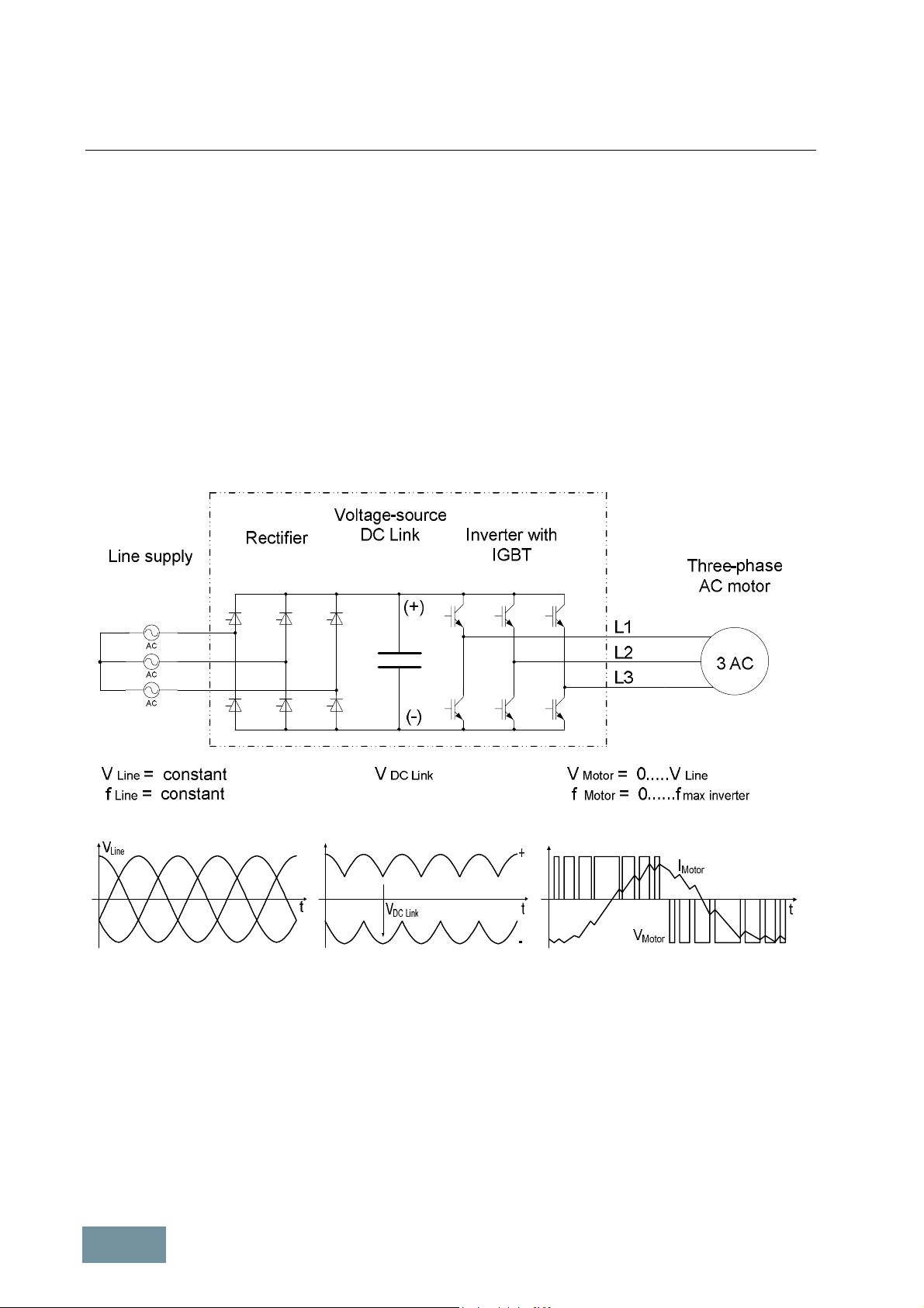
The converters in the SINAMICS product range are PWM converters with a voltage-source DC link. At the input side,
the converter consists of a rectifier (shown in the schematic sketch as a thyristor rectifier) which is supplied with a
constant voltage V
voltage V
DCLink
the output side converts the DC link voltage to a three-phase system with a variable voltage V
frequency f
Motor
voltage and the frequency, it is possible to vary the speed of the connected three-phase motor continuously and
virtually without losses.
and a constant frequency f
Line
from a three-phase supply. The rectifier produces a constant DC
Line
, i.e. the DC link voltage, which is smoothed by the DC link capacitors. The 2-level IGBT inverter on
and variable
Motor
. This process operates according to the principle of pulse-width modulation PWM. By varying the
Block diagram of a PWM converter with voltage-source DC link
1.1.2 Pulse modulation method
The power semiconductors of the IGBT inverter (IGBT = Insulated Gate Bipolar Transistor) are high-speed, electronic
switches which connect the converter outputs to the positive or negative pole of the DC link voltage. The duration of
the gating signals in the individual inverter phases and the magnitude of the DC link voltage thus clearly determine
the output voltage and therefore also the voltage at the connected motor.
16/528
SINAMICS Engineering Manual – November 2015
Ó Siemens AG
Fundamental Principles and System Description
1
2
3
4
5
6
7
8
Engineering Information
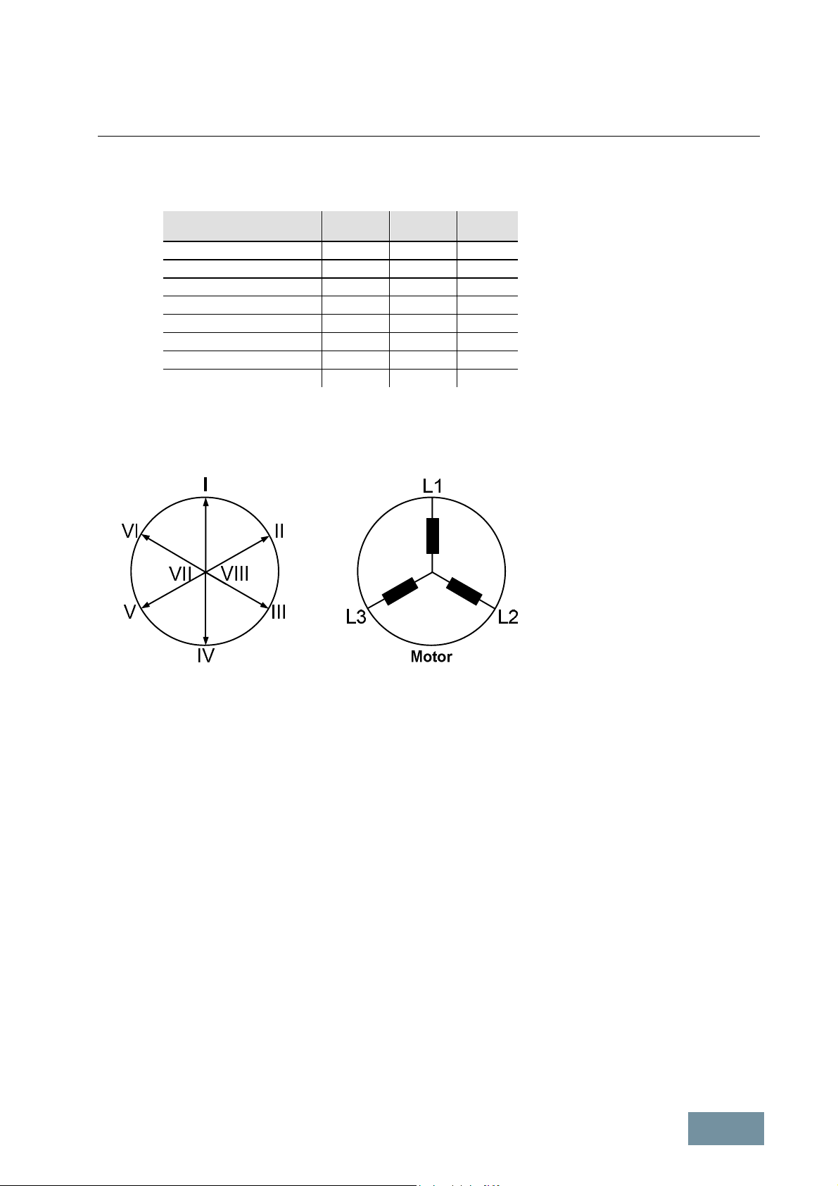
If we consider all three phases, there is a total of 2³ = 8 switching states in the inverter, and the effect of these states
in the motor can be defined by voltage phasors.
Switching states of the
inverter
V
V
V
V
V
V
V
V
Phase
L1
+ - + + -
- + -
- + +
- - +
+ - +
+ + +
- - -
Phase
L2
Phase
L3
If, for example, phase L1 is connected to the positive DC link voltage, and phases L2 and L3 to the negative voltage
so as to produce switching state V1, the resultant voltage phasor points in the direction of motor phase L1 and is
designated phase I. The length of this phasor is determined by the DC link voltage.
Representation of resultant motor voltages as phasor
If the switching state changes from V1 to V2, then the voltage phasor rotates clockwise by an angle of 60°el. due to
the change in potential at terminal L2. The length of the phasor remains unchanged.
In the same way, the relevant voltage phasors are produced by switching combinations V3 to V6. Switching
combinations V7 and V8produce the same potential at all motor terminals. These two combinations therefore produce
voltage phasors of "zero" length (zero voltage phasor).
1.1.2.1 Generation of a variable voltage by pulse-width modulation
Voltage and frequency must be specified in a suitable way for a certain operating state of the motor, characterized by
speed and torque. Ideally, this corresponds to control of the voltage vector V(wt) on a circular path with the speed of
rotation w = 2*p*f and adjusted absolute value. This is achieved through modulation of the actual settable voltage
space vectors (pulse-width modulation). In this way, the momentary value V(wt) is formed by pulses of the adjacent,
actual settable voltage space vectors and the voltage zero.
The solid angle is set directly by varying the ratio of the ON durations (pulse-width) of adjacent voltage vectors, the
desired absolute value by varying the ON duration of the zero voltage vector. This method of generating gating
signals is called space vector modulation SVM. It is used in all units described in this engineering manual. Space
vector modulation provides sine-modulated pulse patterns.
SINAMICS Engineering Manual – November 2015
Ó Siemens AG
17/528
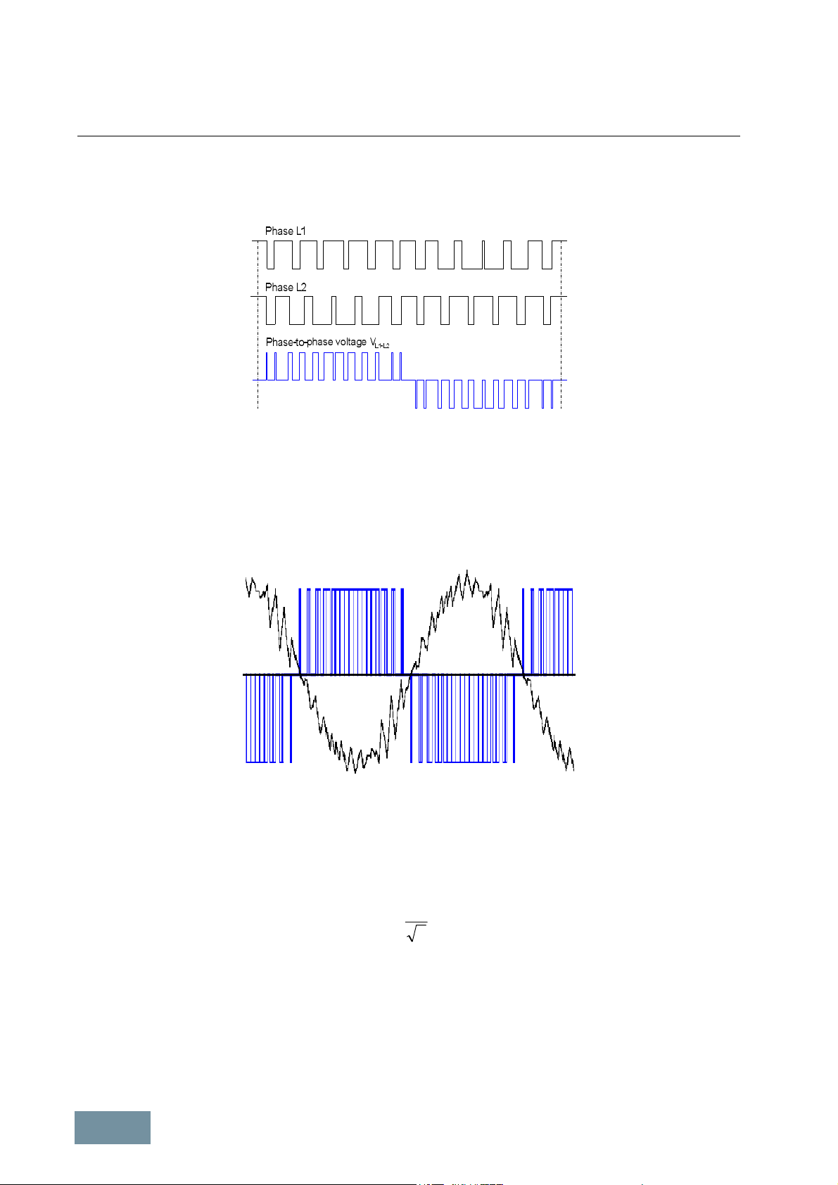
Fundamental Principles and System Description
Engineering Information
The following diagram illustrates how the voltages in phases L1 and L2 plus output voltage V
(phase-to-phase
L1-L2
voltage) are produced by pulse-width modulation or space vector modulation and shows their basic time
characteristics. The frequency with which the IGBTs in the inverter phases are switched on and off is referred to as
the pulse frequency or clock frequency of the inverter.
Timing of the gating signal sequence for the IGBTs in the inverter phases L1 and L2 plus the associated output voltage
(phase-to-phase voltage) V
. The amplitude of the voltage pulses corresponds to the DC link voltage.
L1-L2
The diagram below shows the time characteristic (in blue) of one of the three output voltages of the inverter (phaseto-phase voltage) and the resulting current (in black) generated in one of the three motor phases when a standard
asynchronous motor with a rated frequency of 50 Hz or 60 Hz is used and the inverter is operating with a pulse
frequency of 1.25 kHz. The diagram shows that the smoothing effect of the motor inductances causes the motor
current to be virtually sinusoidal, despite the fact that the motor is supplied with a square-wave pulse pattern.
Motor voltage (phase-to-phase) and motor current with space vector modulation
1.1.2.2 Maximum attainable output voltage with space vector modulation SVM
Space vector modulation SVM generates pulse patterns which approximate an ideal sinusoidal motor voltage through
voltage pulses with constant amplitude and corresponding pulse-duty factor. The peak value of the maximum
(fundamental) voltage that can be attained in this way corresponds to the amplitude of the DC link voltage V
Thus the theoretical maximum motor voltage with space vector modulation which results is:
1
DCLink
VV ×=
2
The amplitude of the DC link voltage V
SVM
max
is determined by the method of line voltage rectification. With line-
DCLink
commutated rectifiers used with SINAMICS G130 and G150 and also with S120 Basic Line Modules, it averages
1.41*V
amplitude of V
with no load, 1.35*V
Line
≈ 1.32*V
DCLink
with partial load and 1.32*V
Line
at full load, the motor voltage theoretically attainable at full load with space vector
Line
.with full load. Thus with the true DC link voltage
Line
modulation without overmodulation is:
18/528
V
SINAMICS Engineering Manual – November 2015
Ó Siemens AG
SVM max
= 0.935* V
Line
.
DCLink
.
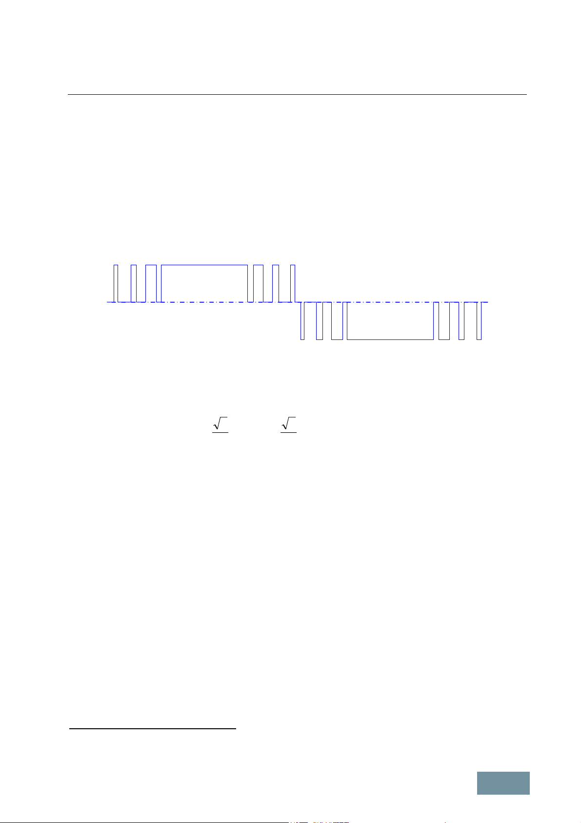
Fundamental Principles and System Description
Engineering Information
As a result of voltage drops in the converter and minimum pulse times and interlock times in the gating unit
responsible for generating the IGBT gating pulse pattern, the values in reality are lower. In practice, therefore, the
value for space vector modulation without overmodulation must be assumed to be as follows:
V
This value applies precisely to pulse frequencies of 2.0 kHz or 1.25 kHz according to the factory setting. At higher
pulse frequencies, it decreases by approximately 0.5 % per kHz.
1.1.2.3 Maximum attainable output voltage with pulse-edge modulation PEM
It is possible to increase the inverter output voltage above the values attained with space vector modulation (SVM) by
pulsing only at the edges of the fundamental-wave period rather than over the entire fundamental-wave period. This
process is referred to as pulse-edge modulation (PEM). The basic waveform of the motor voltage is then as shown
below.
Motor voltage with pulse-edge modulation PEM
SVM max
≈ 0.92* V
Line
The maximum possible output voltage is attained when clocking is performed with the fundamental frequency only,
i.e. when "pulsing" ceases altogether. The output voltage then consists of 120° rectangular blocks with the amplitude
of the DC link voltage. The fundamental frequency RMS value of the output voltage can then be calculated as:
rect
66
pp
LineLineDCLink
VVVV ×=××=×= 03.132.1
So it is possible with pure rectangular modulation to achieve a motor voltage which is slightly higher than the line
voltage. However, the motor voltage then has an unsuitable harmonic spectrum which causes major stray losses in
the motor and utilizes the motor inefficiently. It is for this reason that pure square-wave modulation is not utilized on
SINAMICS converters.
The pulse-edge modulation method used on SINAMICS converters permits a maximum output voltage which is only
slightly lower than the line voltage, even when allowance is made for voltage drops in the converter:
V
PEM max
≈ 0.97* V
Line
The pulse-edge modulation method uses optimized pulse patterns which cause only minor harmonic currents and
therefore utilize the connected motor very efficiently. Commercially available standard asynchronous motors for
50 Hz or 60 Hz operation utilized according to temperature class 130 (previously temperature class B) in operation
directly on line can be utilized according to temperature class 155 (previously temperature class F) when operated
with pulse-edge modulation at the nominal operating point up to rated torque.
Pulse-edge modulation is available as standard in vector control mode (drive object of vector type) on all SINAMICS
units described in this engineering manual:
· SINAMICS G130 *) Chassis
· SINAMICS G150 *) Cabinets
· SINAMICS S150 *) Cabinets
· SINAMICS S120 *) Motor Modules / Chassis format
· SINAMICS S120 *) Motor Modules / Cabinet Modules format
For SINAMICS G130 and G150 converters, the modulator mode (parameter p1802) is automatically preset to value 9
(pulse-edge modulation) since "Pumps and fans" is the default technological application (parameter p0500 = 1). This
is because SINAMICS G converters are predominantly deployed in conjunction with asynchronous motors without
SINAMICS Engineering Manual – November 2015
Ó Siemens AG
19/528
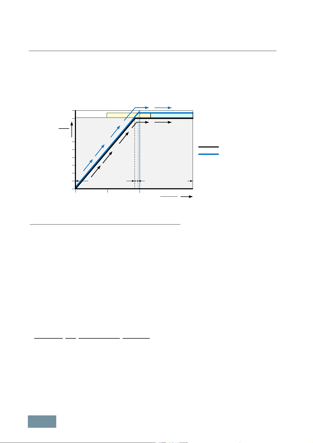
Fundamental Principles and System Description
Engineering Information
speed encoder as independent single drives for applications with simple control requirements. At a low output
frequency and low depth of modulation (output voltage < 92 % of input voltage), these converters utilize space vector
modulation SVM and switch over to pulse-edge modulation PEM automatically if the depth of modulation required at
higher output frequencies is so high that it can no longer be provided by space vector modulation SVM (output
voltage > 92 % of input voltage). The minor irregularities in the torque characteristic caused by transient phenomena
during transition between different modulation systems are virtually irrelevant for applications with simple control
requirements of the kind mentioned above.
100%
90%
VMot
PEM1 PEM2
V = const
V = const
VLine
60%
40%
V ~ f
V ~ f
SVM
SVM
SVM + PEM
20%
Constant-flux range Field-weakening range
0
0
Maximum attainable motor voltage with space vector modulation SVM and pulse-edge modulation PEM
0,5 1,0
fMot
fMot-ra ted
For SINAMICS S120 Motor Modules and SINAMICS S150 converters, the modulator mode (parameter p1802) is
automatically preset to the value 4 (space vector modulation without overmodulation) in vector control mode because
the default technological application is "Standard drive vector" (parameter p0500 = 0). In this case, these units utilize
only space vector modulation SVM because, and this applies particularly to SINAMICS S120 Motor Modules, they
are predominantly used in coordinated multi-motor drive systems with sophisticated control technology which
demand very high control quality (e.g. strip finishing lines, paper-making machines and foil-drawing machines). These
types of application can rarely tolerate the minor irregularities in the torque characteristic caused by transient
phenomena during transition between different modulation systems. If SINAMICS S120 Motor Modules and
SINAMICS S150 converters are required to operate with pulse-edge modulation PEM, the modulator mode
(parameter p1802) must be set to 9 (pulse-edge modulation) during commissioning.
Basically, it would also be possible to achieve depths of modulation or output voltages in excess of 92 % through
overmodulation of the space vector modulation SVM (by setting parameter p1802 to values 0, 1, 2, 5, 6). While it is
possible by this method to prevent the slight irregularities in the torque characteristic on transition between
modulation systems, it also causes the harmonics spectrum in the motor current to increase, resulting in higher
torque ripples and higher motor losses. With a very high level of overmodulation (maximum modulation depth setting
in parameter p1803 > approx. 103 %), the control quality decreases significantly. Pulse-edge modulation PEM with its
optimized pulse patterns therefore offers obvious advantages in this case, as it enables a high depth of modulation
(high output voltage) combined with good drive behavior (in terms of torque accuracy and motor losses) to be
achieved.
*) Exceptions regarding the use of pulse-edge modulation:
Converters with output-side sine-wave filter. Pulse-edge modulation cannot be selected under these conditions.
If either a Basic or Smart Infeed is used to supply the inverter, the following formulae apply for the DC link voltage at
full load: V
DCLink
≈ 1.32 • V
Line
resp. V
DCLink
= 1.30 • V
. In this case, the maximum output voltage is limited to 85 %
Line
of the line input voltage for units with a supply voltage of 380 V to 480 V 3AC and to 83 % for units with a supply
voltage of 500 V to 600 V 3AC.
If an Active Infeed is used to supply the inverter, the following formula applies to the DC link voltage because the
Active Infeed utilizes a step-up converter function: V
DCLink
> 1.42 • V
(factory setting: V
Line
DCLink
= 1.5 • V
Line
). This
means that the maximum output voltage even without pulse-edge modulation can correspond to 100 % of the line
20/528
SINAMICS Engineering Manual – November 2015
Ó Siemens AG

Fundamental Principles and System Description
I
Engineering Information
input voltage or higher if the parameters of ratio V
DCLink
/ V
are set to sufficiently high values on the Active Infeed.
Line
This is described in the section “SINAMICS Infeeds and their properties”, subsection “Active Infeeds”.
Note:
Pulse-edge modulation PEM is available only for vector-type drive objects (vector and V/f control modes) in
combination with current controller clock cycles of ≥ 250 μs and is generally utilized on drives with asynchronous
motors. With servo-type drive objects (servo control mode), converters always operate with space vector modulation
SVM with automatic overmodulation. The reason for this is the slower dynamic response of the drive in operation with
pulse-edge modulation PEM. This is acceptable for many applications with vector control, but not for highly dynamic
applications with servo control.
1.1.3 The pulse frequency and its influence on key system properties
The pulse frequency of the inverter corresponds to the frequency at which the IGBTs are turned on and off in the
inverter phases in operation with space vector modulation SVM. It is an important parameter which has a significant
influence on various properties of the drive system. It can be varied within certain given limits. It might be useful to
increase the pulse frequency from the factory-set value in order, for example, to reduce motor noise. However, it
might also be essential to increase the pulse frequency, for instance, when higher output frequencies are required or
to allow the use of sine-wave filters at the converter output.
An overview of the following aspects of the pulse frequency is given below:
· The pulse frequency factory settings,
· the permissible pulse frequency adjustm ent limits,
· the interrelationships between current controller clock cycle, pulse frequency and output frequency,
· the effects of the pulse frequency on various properties of the drive system, and
· the important points to note in relation to motor-side options (motor reactors, motor filters).
1.1.3.1 Factory settings and ranges of pulse frequency settings
The factory setting of the pulse frequency f
(Chassis and Cabinet Modules formats) with vector-type drive objects (vector and V/f control modes) is 2.0 kHz with a
current controller clock cycle TI = 250 μs or 1.25 kHz with a current controller clock cycle TI = 400 μs in accordance
with the following table.
Line supply voltage Output power Rated output current Factory setting of
380 V to 480 V 3AC ≤ 250 kW ≤ 490 A 2.00 kHz / 250 μs 8.0 kHz
500 V to 600 V 3AC All power ratings All currents 1.25 kHz / 400 μs 7.5 kHz
660 V to 690 V 3AC All power ratings All currents 1.25 kHz / 400 μs 7.5 kHz
Unit-specific factory setting of pulse fr equency and current controller clock cycle for SINAMICS G130, G150, S150 and for
SINAMICS S120 Motor Modules (Chassis and Cabinet Modules formats) for vector-type drive objects (vector and V/f
control modes)
≥ 315 kW ≥ 605 A 1.25 kHz / 400 μs 7.5 kHz
The pulse frequency factory setting can be increased in discrete steps. The possible settings for the pulse frequency
f
are dependent upon the current controller clock cycle setting TI according to the following equation
Pulse
f
= n • (1 / TI) where n = ½, 1, 2, 3, ... .
Pulse
of the motor-side inverter for SINAMICS G130, G150, S150 and S120
Pulse
Maximum possible
pulse frequency f
and current controller
clock cycle T
Pulse
pulse frequency of
power unit
In addition the limits given by the relevant power units according to the table above, as well as the current derating
factors specified in the chapters about specific unit types must be taken into account. Depending on these criteria,
the pulse frequency can therefore be raised to 8 kHz or 7.5 kHz, depending on the unit type. It is possible to switch at
any time between pulse frequencies, which are calculated for a constant current controller clock cycle setting
according to the equation given above, for vector-type drive objects (vector and V/f control modes), even when the
SINAMICS Engineering Manual – November 2015
Ó Siemens AG
21/528

Fundamental Principles and System Description
Engineering Information
unit is in operation, by changing a parameter setting or switching to another data set, for example. By altering the
current controller clock cycle, it is also possible to set different pulse frequency values, in other words, the pulse
frequency can be very finely adjusted. However, the current controller clock cycle can be changed only when the
drive is in commissioning mode.
1.1.3.2 Interrelationships between current controller clock cycle, pulse frequency and output
frequency
For SINAMICS G130, G150, S150 and S120 converters and inverters (Chassis and Cabinet Modules formats)
described in this engineering manual and vector-type drive objects (vector and V/f control modes), the following
interdependencies exist between the current controller clock cycle, the pulse frequency and the output frequency:
Dependence of the settable pulse frequency f
f
= n • (1 / TI) where n = ½, 1, 2, 3, … .(applies to vector and V/f control modes) (1)
Pulse
on the current controller clock cycle setting TI:
Pulse
Dependence of the maximum attainable output frequency f
f
≤ 1 / (8.3333 • TI) . (applies only to vector control mode but not to V/f control mode) (2)
out max
Dependence of the maximum attainable output frequency f
f
≤ f
out max
/ 12 . (applies to vector and V/f control modes) (3)
Pulse
Regardless of the formulas specified above, the maximum possible output frequency f
on the current controller clock cycle setting TI:
out max
on the pulse frequency setting f
out max
is limited to 550 Hz in
out max
Pulse
:
the standard firmware for the vector and U/f control modes with SINAMICS G and S. With the license "High output
frequency" (6SL3074-0AA02-0AA0) for SINAMICS S (which can also be ordered as option J01 for the SINAMICS S
CompactFlash card), it is now possible to increase the maximum possible output frequency f
to 650 Hz. The
out max
"High output frequency" license is subject to export restrictions. Further information is available on request.
When firmware version 4.3 is used, the minimum settable current controller clock cycle is 250 μs for vector-type drive
objects (vector and V/f control modes) of all SINAMICS G and SINAMICS S Chassis and cabinet units.
When firmware version 4.4 or higher is used, a minimum current controller clock cycle of 125 μs can be set for
vector-type drive objects (vector and V/f control modes) of SINAMICS S Chassis and cabinet units. The only
exceptions are the parallel connections of SINAMICS S converters for which the minimum permissible current
controller clock cycle is 200 μs. For SINAMICS G converters, the minimum permissible current controller clock cycle
setting remains 250 μs and the minimum permissible speed controller clock cycle is also unchanged at 1 ms.
Vector-type drive object with vector control mode
For vector control mode the table below shows the settable pulse frequencies f
attainable output frequencies f
as a function of the current controller clock cycle setting TI in accordance with
out max
and the associated maximum
Pulse
equations (1) to (3) (which must all be satisfied simultaneously).
Current
controller
clock cycle
125 μs
(FW version 4.4
or higher
for SINAMICS S)
200 μs
(FW version 4.4
or higher
for SINAMICS S)
2
250 μs
SINAMICS G + S
3
400 μs
SINAMICS G + S
500 μs
SINAMICS G + S
1
Only with the license "High output frequency" that is available as option J01 for the SINAMICS S CompactFlash card
Settable pulse frequenci es and associated max. output frequencies (exact, non-rounded values)
4.00 kHz
333 Hz
1.00 kHz
83 Hz
1.25 kHz
104 Hz
2.00 kHz
166 Hz
2.00 kHz
166 Hz
2.50 kHz
208 Hz
4.00 kHz
333 Hz
2.50 kHz
208 Hz
4.00 kHz
240 Hz
5.00 kHz
416 Hz
5.00 kHz
300 Hz
7.5 kHz
300 Hz
6.00 kHz
240 Hz
8.0 kHz
550 Hz /
650 Hz
8.0 kHz
480 Hz
8.0 kHz
240 Hz
1
22/528
SINAMICS Engineering Manual – November 2015
Ó Siemens AG

Fundamental Principles and System Description
Engineering Information
2
The factory settings for current controller clock cycle and pulse frequency are 250 μs and 2.00 kHz respectively for the
SINAMICS G and S converters below. Their maximum settable pulse frequency is 8.0 kHz:
- 380 V – 480 V 3AC: ≤ 250 kW / 490 A or 510 V – 720 V DC: ≤ 250 kW / 490 A
3
The factory settings for current controller clock cycle and pulse frequency are 400 μs and 1.25 kHz respectively for the
SINAMICS G and S converters below. Their maximum settable pulse frequency is 7.5 kHz:
- 380 V – 480 V 3AC: ≥ 315 kW / 605 A or 510 V – 720 V DC: ≥ 315 kW / 605 A
- 500 V – 600 V 3AC: All power ratings or 675 V – 900 V DC: All power ratings
- 660 V – 690 V 3AC: All power ratings or 890 V – 1035 V DC: All power ratings
In the vector-type drive object with vector control mode settable pulse frequencies and associated maximum attainable
output frequencies as a function of the current controller clock cycle setting for SINAM ICS G130, G150, S150 and S120 in
Chassis and Cabin et Modules formats.
Vector-type drive object with V/f control mode
For V/f control mode the table below shows the settable pulse frequencies f
attainable output frequencies f
as a function of the current controller clock cycle setting TI in accordance with
out max
equations (1) and (3) on the previous page (which must all be satisfied simultaneously).
Current controller
clock cycle
125 μs
(FW version ≥ 4.4
for SINAMICS S)
200 μs
(FW version ≥ 4.4
for SINAMICS S)
2
250 μs
SINAMICS G + S
3
400 μs
SINAMICS G + S
500 μs
SINAMICS G + S
1
Only with the license "High output frequency" that is available as option J01 for the SINAMICS S CompactFlash card
2
The factory settings for current controller clock cycle and pulse frequency are 250 μs and 2.00 kHz respectively for the
SINAMICS G and S converters below. Their maximum settable pulse frequency is 8.0 kHz:
- 380 V – 480 V 3AC: ≤ 250 kW / 490 A or 510 V – 720 V DC: ≤ 250 kW / 490 A
3
The factory settings for current controller clock cycle and pulse frequency are 400 μs and 1.25 kHz respectively for the
SINAMICS G and S converters below. Their maximum settable pulse frequency is 7.5 kHz:
- 380 V – 480 V 3AC: ≥ 315 kW / 605 A or 510 V – 720 V DC: ≥ 315 kW / 605 A
- 500 V – 600 V 3AC: All power ratings or 675 V – 900 V DC: All power ratings
- 660 V – 690 V 3AC: All power ratings or 890 V – 1035 V DC: All power ratings
In the vector-type drive object with V/f control mode settable pulse frequencies and associated maximum attainable output
frequencies as a funct ion of the current controller clock cycle setting for SINAM ICS G130, G150, S150 and S120 in Ch assis
and Cabin et Modules formats.
Settable pulse frequenci es and associated max. output frequencies (exact, non-rounded values)
4.00 kHz
333 Hz
1.00 kHz
83 Hz
1.25 kHz
104 Hz
2.00 kHz
166 Hz
2.00 kHz
166 Hz
2.50 kHz
208 Hz
4.00 kHz
333 Hz
2.50 kHz
208 Hz
4.00 kHz
333 Hz
5.00 kHz
416 Hz
5.00 kHz
416 Hz
Notes:
· The maximum attainable output frequency value for SINAMICS S converters described in this engineering
manual for vector-type drive objects in vector control mode is 550 Hz. With the license "High output
frequency", it is possible to increase the output frequency to maximum 650 Hz for SINAMICS S units. To
achieve this output frequency, a power unit is required, which is designed for a maximum pulse frequency of
8.0 kHz (table above), which is not operated in a parallel connection, and which operates with a current
controller clock cycle of 125 μs (settable on SINAMICS S with firmware version 4.4 or higher). In the case of
power units which are designed for a maximum pulse frequency of only 7.5 kHz (table above) and are not
operated in a parallel connection, the maximum attainable output frequency is 623 Hz. To obtain this output
frequency, a current controller clock cycle of 133.75 μs is required (settable on SINAMICS S with firmware
version 4.4 or higher) and a pulse frequency of 7.477 kHz.
· By altering the current controller clock cycle in the range between 125 μs and 500 μs (with SINAMICS S) or
250 μs and 500 μs (with SINAMICS G), it is possible to set other pulse frequency values than those stated in
the table above, although it must be noted that the three equations (1) to (3) on the previous page must still
all be satisfied simultaneously. However, when units communicate in isochronous mode (e.g. via
isochronous PROFIBUS), the only permissible current controller clock cycle is 125 μs or whole multiples
and the associated maximum
Pulse
7.5 kHz
550 Hz /
1
623 Hz
6.00 kHz
500 Hz
8.0 kHz
550 Hz /
650 Hz
8.0 kHz
550 Hz /
650 Hz
8.0 kHz
550 Hz /
650 Hz
1
1
1
SINAMICS Engineering Manual – November 2015
Ó Siemens AG
23/528

Fundamental Principles and System Description
Engineering Information
thereof. Furthermore, the current controller clock cycle must be selected such that the set bus clock cycle
also corresponds to a whole multiple of the current controller clock cycle. When SINAMICS Link is used, bus
clock cycles of 500 μs, 1000 μs or 2000 μs can be set which means that the following current controller
clock cycles can be selected: 125 μs, 250 μs and 500 μs. For further information, refer to the function
manual "SINAMICS S120 Drive Functions" and the List Manuals.
· When the pulse frequency is set higher than the relevant factory setting, the current derating factors
applicable to the specific unit must be observed. These can be found in the chapters on specific unit types.
· If multiple Motor Modules (axes) are to be controlled by a single CU320-2 Control Unit in SINAMICS S multi-
motor drives, it must be noted that the maximum possible number of Motor Modules (axes) is dependent
upon the current controller clock cycle. More detailed information can be found in section "Determination of
the required control performance of the CU320-2 Control Unit" in chapter "General Information about Built-in
and Cabinet Units SINAMICS S120".
1.1.3.3 Influence of the pulse frequency on the inverter output current
The pulse frequency factory setting of either 2.0 kHz or 1.25 kHz is relatively low in order to reduce inverter switching
losses. If the pulse frequency is increased the inverter switching losses and thus also the total losses in the converter
increase accordingly. The result would be overheating of the power unit when operating at full load capacity. For this
reason, the conducting losses must be lowered in order to compensate for the increase in switching losses. This can
be achieved by reducing the permissible output current (current derating). The current derating factors as a function
of pulse frequency are unit-specific values and must be taken into account when the converter is dimensioned. The
derating factors for various pulse frequencies can be found in the chapters on specific unit types. If derating factors
are required for pulse frequencies which are not included in the tables, they can be calculated by linear interpolation
between the stated table values. Under certain boundary conditions (line voltage at low end of permissible widevoltage range, low ambient temperature, restricted speed range), it is possible to partially or completely avoid current
derating at pulse frequencies which are twice as high as the factory setting. For further information, please refer to
section "Operation of converters at increased pulse frequency".
1.1.3.4 Influence of the pulse frequency on losses and efficiency of inverter and motor
With the factory-set pulse frequency of 2.0 kHz or 1.25 kHz, the motor current is already close to sinusoidal. The
stray losses in the motor caused by harmonic currents are low, but not negligible. Commercially available standard
motors for 50 Hz or 60 Hz operation utilized according to temperature class 130 (previously temperature class B) in
operation directly on line can be utilized according to temperature class 155 (previously temperature class F) at the
nominal working point up to rated torque when operated on a converter. The winding temperature rise is then
between 80 and 100 K.
Raising the pulse frequency on standard motors for 50 Hz or 60 Hz reduces the motor stray losses only slightly, but
results in a considerable increase in the converter switching losses. The efficiency of the overall system (converter
and motor) deteriorates as a result.
1.1.3.5 Influence of the pulse frequency on the motor noise
A higher level of magnetic motor noise is excited when three-phase motors are operated on PWM converters as
compared to operation directly on line at 50/60 Hz supply systems. This is caused by the voltage pulsing which
results in additional voltage and current harmonics.
According to
· IEC/TS 60034-17:2006 "Rotating electrical Machines – Part 17: Cage induction motors when fed from converters
- Application guide“,
and
· IEC/TS 60034-25:2007 "Rotating electrical Machines – Part 25: Guidance for the design and performance of a.c.
motors specifically designed for converter supply",
the A-graded noise pressure level increases up to 15 dB(A) when three-phase motors are operated on a PWM
converter up to rated frequency as compared to motors of the same type operating on pure sinusoidal voltage.
24/528
SINAMICS Engineering Manual – November 2015
Ó Siemens AG
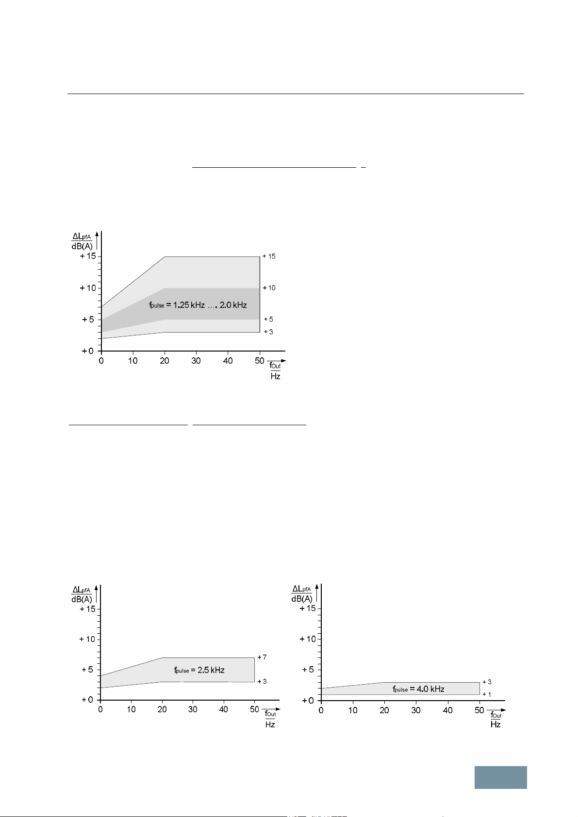
Fundamental Principles and System Description
Engineering Information
The actual values depend on the PWM method used and the pulse frequency of the converter on the one hand, and
the design and number of poles of the motor on the other.
In the case of SINAMICS converters operating in vector control mode (drive object of vector type) at the factory-set
pulse frequency (1.25 kHz or 2.0 kHz), the increase in A-graded noise pressure level produced by the motor as a
result of the converter supply is typically within the 5 dB(A) to 10 dB(A) range.
The diagram below shows the scatter range of the increase in the A-graded noise pressure level ΔL
produced by
pfA
the motor in converter-fed operation as compared to operation directly on line at a 50 Hz supply system. This applies
to fin-cooled motors with 2, 4, 6 and 8 poles operating at the factory-set pulse frequency of 1.25 kHz or 2.0 kHz. The
values are lower for water-jacket-cooled motors and SIMOTICS TN series H-compact PLUS motors.
Increase in motor noise at operation on the factory-set
pulse frequency of 1.25 kHz or 2.0 kHz
Reduction in motor noise through increase in pulse frequency
By raising the pulse frequency, it is generally possible to lessen the increase in motor noise associated with
converter-fed operation. It must be noted, however, that raising the pulse frequency also necessitates inverter current
derating. Under certain boundary conditions (line voltage at low end of permissible wide-voltage range, low ambient
temperature, restricted speed range), it is possible to partially or completely avoid current derating at pulse
frequencies which are twice as high as the factory setting. For further information, please refer to section "Operation
of converters at increased pulse frequency". Increasing the pulse frequency not only necessitates current derating,
but might also impose limits on other motor-side options, such as motor reactors, dv/dt filters and sine-wave filters.
The diagram below shows the scatter range of the increase in the A-graded noise pressure level ΔL
produced by
pfA
the motor in converter-fed operation as compared to operation direcly on line at a 50 Hz - supply system. This applies
to fin-cooled motors with 2, 4, 6 and 8 poles operating at pulse frequencies of 2.5 kHz or 4.0 kHz which are higher
than the factory-set pulse frequencies. The values are lower for water-jacket-cooled motors and SIMOTICS TN series
H-compact PLUS motors.
Increase in motor noise at pulse frequencies of 2.5 kHz or 4.0 kHz (i.e. at higher than factory-set pulse frequencies)
SINAMICS Engineering Manual – November 2015
Ó Siemens AG
25/528

Fundamental Principles and System Description
Engineering Information
Reduction in motor noise through pulse frequency wobbling
"Pulse frequency wobbling" can be activated via parameter p1810 / Bit 02 = 1 for Chassis units and cabinet units (not
possible on earlier units with CIB module and CU320 Control Unit with firmware versions < 2.6). The wobble
amplitude is set in parameter p1811. Pulse frequency wobbling uses a statistical method to vary the pulse frequency
according to the setting in parameter p1811. The mean pulse frequency value still corresponds to the set value, but
the statistical variation of the momentary value produces a modified noise spectrum. The subjectively perceptible
motor noise diminishes as a result, especially at the relatively low factory-set pulse frequencies. For further details
about parameter assignments, please refer to the function manual "SINAMICS S120 Drive Functions" and the list
manuals.
Note:
§ Pulse frequency wobbling can be activated only on power units in Chassis format.
§ Pulse frequency wobbling is possible only in the vector and V/f control modes, but not in servo control mode.
§ The maximum pulse frequency f
Pulse max
i.e.:
f
Pulse max
= 4 kHz with current controller clock cycle of 250 μs and f
clock cycle of 400 μs.
§ Pulse frequency wobbling is not possible with current controller clock cycles of < 250 μs
1.1.3.6 Correlation between pulse frequency and motor-side options
If motor reactors, dv/dt filters plus VPL, dv/dt filters compact plus VPL or sine-wave filters are installed at the
converter output, the maximum permissible pulse frequency and the maximum output frequency are limited by these
options. In some cases, a fixed pulse frequency is specified:
· Permissible pulse frequency with motor reactor (SINAMICS):
The maximum pulse frequency is limited to twice the value of the factory setting, i.e. to 4 kHz on units with
factory setting 2 kHz and to 2.5 kHz on units with factory setting 1.25 kHz. The maximum output frequency is
limited to 150 Hz independent of the selected pulse frequency.
· Permissible pulse frequency with dv/dt filter plus VPL and dv/dt filter compact plus VPL (SINAMICS)
The maximum pulse frequency is limited to twice the value of the factory setting, i.e. to 4 kHz on units with
factory setting 2 kHz and to 2.5 kHz on units with factory setting 1.25 kHz. The maximum output frequency is
limited to 150 Hz independent of the selected pulse frequency.
· Permissible pulse frequency with sine-wave filter (SINAMICS):
Sine-wave filters are available for voltage levels 380 V to 480 V 3AC and 500 V to 600 V 3AC. The pulse
frequency is a mandatory fixed value and equals 4 kHz (380 V to 480 V) or 2.5 kHz (500 V to 600 V). The
maximum output frequency is limited to 150 Hz (380 V – 480 V) or 115 Hz (500 V – 600 V).
· Permissible pulse frequency with sine-wave filter (external supplier):
The pulse frequency and maximum output frequency must be set according to the filter manufacturer's
instructions.
with wobbling equals f
Pulse max
Pulse max
= 1/current controller clock cycle,
= 2.5 kHz with current controller
26/528
SINAMICS Engineering Manual – November 2015
Ó Siemens AG
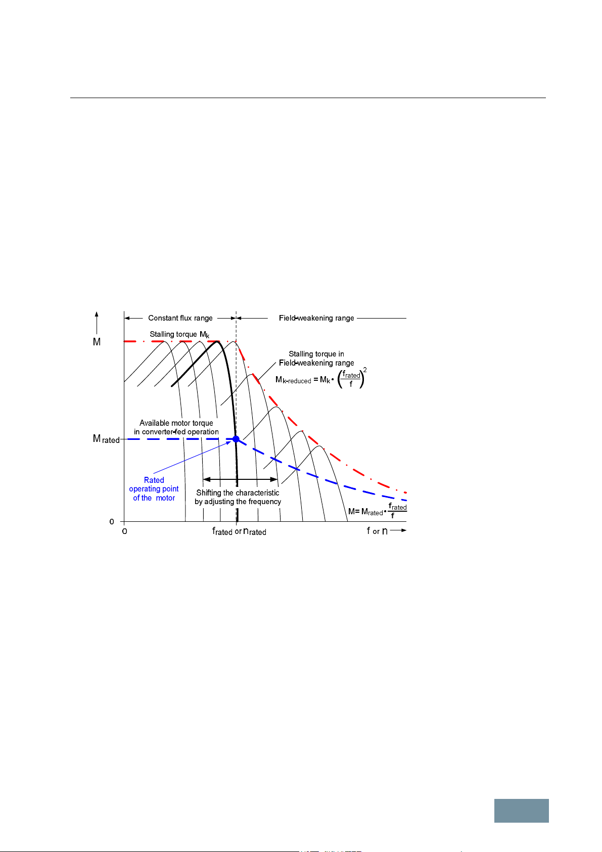
Fundamental Principles and System Description
Engineering Information
1.1.4 Open-loop and closed-loop control modes
The standard firmware of the SINAMICS converters of type G130, G150, S120 and S150 described in this manual
offers a range of different open-loop and closed-loop control modes for three-phase motors:
· V/f open-loop control modes for applications with simple control requirements
· Field-oriented closed-loop control modes for applications which require highly precise and highly dynamic
control functionality
1.1.4.1 General information about speed adjustment
The steady-state speed/torque characteristic of an asynchronous motor can be shifted in converter-fed operation
through adjustment of the frequency and voltage, as illustrated in the diagram below. The speed/torque characteristic
in "bold" print represents the motor's characteristic when it is operating directly on the mains supply at rated
frequency f
and rated voltage V
rated
rated
.
Shifting the speed/torque characteristic of an asynchronous motor by adjusting frequency and voltage
As long as the voltage is adjusted in proportion to the frequency, the ratio between voltage and frequency remains
constant and thus also the magnetic flux, the available torque and the stalling torque of the motor. This is known as
the constant flux range or the base speed range.
If the frequency is increased further after the maximum possible output voltage of the converter has been reached,
the ratio between voltage and frequency decreases again and thus also the magnetic flux in the motor. This is known
as the field-weakening range. With asynchronous motors operating in the field weakening range, the available torque
M decreases in relation to the rated torque M
remains constant. The stalling torque in the field-weakening range M
torque Mk in the constant flux range in proportion to the ratio (f
approximately in proportion to the ratio f
rated
decreases in relation to the stalling
k-reduced
/f)2.
rated
/f. The output power
rated
1.1.4.2 V/f control modes
V/f control is a simple method of adjusting the speed of three-phase motors. V/f control is based on the principle of
varying the frequency in order to adjust the motor speed, while at the same time applying a voltage setpoint
according to the characteristic of the V/f curve selected in the firmware. The gating unit generates pulse patterns to
control the IGBTs in the three phases of the converter's power unit.
SINAMICS Engineering Manual – November 2015
Ó Siemens AG
27/528

Fundamental Principles and System Description
Engineering Information
Diagram of the basic stru cture of the V/f control method
The voltage is adjusted as a function of frequency according to the V/f characteristic with the aim of maintaining the
motor flux as constantly as possible at the rated flux value, irrespective of speed or frequency.
At low frequencies, the ohmic stator resistance of the motor in relation to inductance is not negligible, which means in
this case that the voltage of the V/f characteristic must be boosted relative to the linear curve in order to compensate
for the voltage drop across the stator resistance.
At high frequencies, the maximum possible output voltage V
knee point in the V/f characteristic. The knee point generally corresponds to the rated operating point of the
connected motor. If the frequency is further increased beyond the knee point, the ratio between voltage and
frequency decreases due to the constant voltage. The motor flux is then also reduced, causing the motor to operate
in the field-weakening range.
V/f control modes are available in the standard firmware of the SINAMICS converters described in this engineering manual
(SINAMICS G130, G150, S120, S150) in the vector drive object. The following V/f control modes can be selected:
· V/f control with linear characteristic
· V/f control with parabolic characteristic
· V/f control with freely parameterizable characteristic
· V/f control for high-precision frequency-controlled drives in the textiles sector
· V/f control with independent voltage setpoint
In order to optimize the performance of drives operating in V/f control mode, the following functions have been
provided in the SINAMICS firmware:
· Slip compensation: For the purpose of increasing accuracy of speed, the frequency is adapted as a function
of load current in order to compensate the slip of the connected asynchronous motor.
· Flux current control (FCC): For the purpose of increasing accuracy of speed, voltage and flux are adapted
as a function of load.
· Resonance damping: The resonance damping function dampens electromechanical oscillations in the
frequency range up to a few tens of hertz.
· Current limiting control: The current limiting control prevents the connected asynchronous motor from
stalling and thus functions as stall protection.
of the converter is reached, resulting in a horizontal
max
The advantages of the V/f control method lie in its simplicity and its ability to withstand parameter fluctuations, such
as changes in resistance caused by temperature rise or changeover of the motor operating on the converter.
Furthermore, this control method fully supports converter-fed operation of multi-motor drives. Its disadvantages lie in
its lack of precision and dynamic response, particularly at low speeds and in the field weakening range.
28/528
SINAMICS Engineering Manual – November 2015
Ó Siemens AG
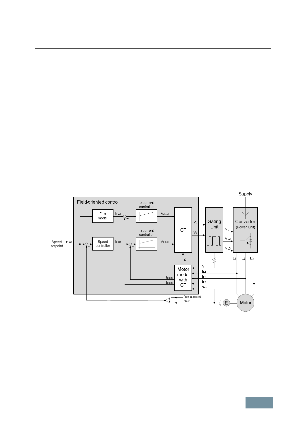
Fundamental Principles and System Description
Engineering Information
In view of these properties, use of the V/f control method is recommended primarily for asynchronous motor drives
with low requirements of accuracy and dynamic response, and for asynchronous motor drives with limited speed
range and low torque requirements at low speeds. The V/f control method can be usefully employed up to an output
power of about 100 kW – 200 kW, and for multi-motor drives with asynchronous or SIEMOSYN motors. The higher
the motor power, the greater the tendency to oscillate at low frequencies. For this reason, drives of this type need to
be commissioned carefully. This applies in particular to the resonance damping function.
1.1.4.3 Field-oriented control modes
Field-oriented control is a sophisticated method of controlling three-phase motors. With field-oriented control, the
equations which describe the motor are not referred to the fixed coordinate system of the stator (α-β coordinates), but
instead to the rotating magnetic field of the rotor (d-q coordinates). In this rotating coordinate system which is rotorfield-orientated, the stator current can be split into two components, i.e. the field-producing component Id and the
torque-producing component Iq.
· The field-producing current component Id is responsible for the magnetic field in the motor and is thus
comparable to the excitation current in a DC motor.
· The torque-producing current component Iq is responsible for the motor torque and is thus comparable to
the armature current in a DC motor.
The resulting control structure is therefore comparable to the DC motor. Thanks to the independent and direct control
of the field-producing current component Id and the torque-producing current component Iq, a high degree of
accuracy and, more importantly, an excellent dynamic response are achieved with this control method.
The diagram below illustrates the basic structure of the field-oriented control method for an asynchronous motor.
Diagram of the basic structure of the field-oriented control method for an asynchronous motor
The three measured actual motor current values IL1, IL2 and IL3 are converted into the two current components I
and I
(CT). The values of I
of the rotating d-q coordinate system by means of a motor model which includes a coordinate transformation
q act
d act
and I
are constant in the case of a symmetrical three-phase system in the motor with
q act
d act
purely sinusoidal motor currents which are out of phase by 120° in each case. They are compared to their setpoints
(I
and I
d set
controller outputs provide the two voltage components V
respectively) and applied to the Id current controller and Iq current controller respectively. The
q set
d set
and V
in the rotating d-q coordinate system. The
q set
following coordinate transformation (CT) converts the two voltage components into the fixed α-β coordinate system.
The angle ρ between the rotating d-q coordinate system and the fixed α-βcoordinate system, which is required to
convert the coordinates, is calculated by the motor model. Using the two voltage components Vα and Vβ, the gating
unit generates pulse patterns to control the IGBTs in the three phases of the power unit of the converter.
SINAMICS Engineering Manual – November 2015
Ó Siemens AG
29/528

Fundamental Principles and System Description
Engineering Information
On drives which require a very high degree of precision, especially at very low speeds down to zero speed, or drives
which demand an excellent dynamic response, the actual speed value n
(E) and then passed to the motor model and the speed controller. Drives without high requirements of precision
and/or dynamic response do not need a speed encoder. In this case the actual speed value n
by the motor model and used instead of the speed encoder signal (encoderless control).
The quality of the field-oriented control critically depends on precise knowledge of the position of the magnetic field in
the motor and thus on the quality of the motor model. Only with precise field orientation direct and independent
access to the magnetic field and the torque is possible. For this reason, the motor model must be precisely tuned to
the connected motor. This tuning is part of the drive commissioning process. The rating plate data of the motor must
be input first. The motor is then automatically identified by the converter itself (measurements when motor is at
standstill and when motor is rotating).
Two types of field-oriented control modes are available for SINAMICS converters:
Vector control
Vector control is available as drive object of vector type in the standard firmware of all the SINAMICS converters
described in this engineering manual (SINAMICS G130, G150, S120, S150). The following vector control modes can
be selected:
· Speed control with and without encoder (only TTL / HTL incremental encoders may be used as encoders for
SINAMICS G130 / G150 converters)
· Torque control with and without encoder (only TTL / HTL incremental encoders may be used as encoders
for SINAMICS G130 / G150 converters)
is generally measured by a speed encoder
act
act calculated
is computed
The advantages of vector control lie in its very high torque accuracy and its high dynamic response. Relatively high
complexity as well as significant sensitivity to parameter fluctuations, such as changes in resistance caused by
temperature rise, are the disadvantages of this control mode. To achieve particularly high accuracy over the entire
speed range, therefore, it is important that the motor identification process is performed properly, that the effects of
temperature rise are compensated by use of a KTY motor temperature sensor and that friction compensation based
on recording of the friction characteristic is provided if necessary.
The control characteristics, such as rise times, accuracy, ripple, etc., as a function of current controller cycle settings
and motor types used can be found in the sections on specific unit types.
Typical applications for vector control are speed-controlled asynchronous motor drives with very high speed and
torque stability in general machine engineering, such as those employed, for example, on paper-making machines,
winders, coilers and lifting gear. However, permanent-magnet synchronous motors and separately excited
synchronous motors can also be operated in vector control mode.
Servo control
Servo control is available as drive object of servo type in the standard firmware of all SINAMICS S120 units. The
following servo control modes can be selected:
· Speed control with and without encoder
· Torque control with encoder
· Position control with encoder
The advantages of servo control lie in its outstandingly high dynamic response, especially in cases where it is
possible to parameterize very short current controller cycles of < 250 μs. Its disadvantage lies in its torque accuracy
which is lower than that provided by vector control.
The control characteristics, such as rise times, accuracy, ripple, etc., as a function of current controller cycle settings
and motor types used can be found in chapter "General Information about Built-in and Cabinet Units SINAMICS
S120".
Typical applications for servo control are drives with highly dynamic motion control, such as those used in machine
tools, clocked production machines and industrial robots.
30/528
SINAMICS Engineering Manual – November 2015
Ó Siemens AG
 Loading...