

Siemens SINAMICS G120,SINAMICS G120C,SINAMICS G120P Operating Instructions Manual

SINAMICS G120C
SINAMICS G120
Inverter with CU230P
2,
CU250S
s
-2 Control Units
Product information 07/2015
-2, CU240B/E-
Modified behavior when commissioning the drive
With firmware V4.7 SP3, the commissioning Wizard has been revised and standardized for the
following inverters:
• SINAMICS G120 with PM240, PM240-2 or PM330 Power Module
• SINAMICS G120C
The SINAMICS application classes Standard Drive Control, Dynamic Drive Control and Expert
have been newly developed. The commissioning Wizard sets the application class depending on
the particular inverter:
• Standard Drive Control for SINAMICS G120C and SINAMICS G120 with Power Module
PM240, PM240-2 up to frame size FSD
• Dynamic Drive Control for SINAMICS G120 with PM240, PM240-2 Power Modules from
frame size FSD and with PM330 Power Modules
• Expert for SINAMICS G120 with PM230, PM250 and PM260 Power Modules
Motor data identification (MotID) is permanently set for Standard Drive Control. After the
commissioning Wizard has been exited, the inverter responds to the first ON command as follows:
1. The inverter carries out a MotID with the motor at a standstill. The duration of the MotID,
when compared to firmware V4.7, was shortened to approx. ⅓.
2. The inverter accelerates the motor to the specified setpoint. The second ON command
after the MotID is not necessary for Standard Drive Control.
For Dynamic Drive Control, a MotID is also set as default with the motor at a standstill. The default
setting can be changed:
• In addition, you can also select the MotID with rotating measurement. The inverter
optimizes the closed-loop speed control based on the results of the rotating measurement.
• You can select as to whether, after the MotID, the motor immediately accelerates to the
specified setpoint, or a second ON command is required.
To a large extent, Expert corresponds to the commissioning Wizard for firmware < V4.7 SP3.
A MotID is not set as default. You can select the following:
• No MotID, MotID with measurement with the motor at a standstill or MotID with rotating
measurement
• After the MotID, the motor immediately accelerates to the specified setpoint, or only after a
second ON command.
The following commissioning tools support the new commissioning wizard:
• STARTER from 4.4 SP1 or higher
• Startdrive from V13 SP1 and higher with Hardware Support Package V4.7 SP3
• IOP from V1.6 and higher
• BOP-2

Converter with CU230P-2 Control Units
___________________
___________________
___________________
___________________
___________________
___________________
___________________
___________________
___________________
___________________
___________________
___________________
SINAMICS
SINAMICS G120P
Converter with CU230P-2 Control
Units
Operating Instructions
Edition 04/2015, Firmware V4.7 SP3
Original instructions
04/2015, FW V4.7 SP3
A5E34257946B AB
Changes in this manual
Fundamental safety
instructions
1
Introduction
2
Description
3
Installing
4
Commissioning
5
Advanced commissioning
6
Backing up data and series
commissioning
7
Corrective maintenance
8
Alarms, faults and system
messages
9
Technical data
10
Appendix
A

Legal information
Warning notice system
DANGER
indicates that death or severe personal injury will result if proper precautions are not taken.
WARNING
indicates that death or severe personal injury may result if proper precautions are not taken.
CAUTION
indicates that minor personal injury can result if proper precautions are not taken.
NOTICE
indicates that property damage can result if proper precautions are not taken.
Qualified Personnel
personnel qualified
Proper use of Siemens products
WARNING
Siemens products may only be used for the applications described in the catalog and in the relevant technical
maintenance are required to ensure that the products operate safely and without any problems. The permissible
ambient conditions must be complied with. The information in the relevant documentation must be observed.
Trademarks
Disclaimer of Liability
This manual contains notices you have to observe in order to ensure your personal safety, as well as to prevent
damage to property. The notices referring to your personal safety are highlighted in the manual by a safety alert
symbol, notices referring only to property damage have no safety alert symbol. These notices shown below are
graded according to the degree of danger.
If more than one degree of danger is present, the warning notice representing the highest degree of danger will
be used. A notice warning of injury to persons with a safety alert symbol may also include a warning relating to
property damage.
The product/system described in this documentation may be operated only by
task in accordance with the relevant documentation, in particular its warning notices and safety instructions.
Qualified personnel are those who, based on their training and experience, are capable of identifying risks and
avoiding potential hazards when working with these products/systems.
Note the following:
documentation. If products and components from other manufacturers are used, these must be recommended
or approved by Siemens. Proper transport, storage, installation, assembly, commissioning, operation and
All names identified by ® are registered trademarks of Siemens AG. The remaining trademarks in this publication
may be trademarks whose use by third parties for their own purposes could violate the rights of the owner.
We have reviewed the contents of this publication to ensure consistency with the hardware and software
described. Since variance cannot be precluded entirely, we cannot guarantee full consistency. However, the
information in this publication is reviewed regularly and any necessary corrections are included in subsequent
editions.
for the specific
Siemens AG
Division Digital Factory
Postfach 48 48
90026 NÜRNBERG
GERMANY
A5E34257946B AB
Ⓟ 06/2015 Subject to change
Copyright © Siemens AG 2009 - 2015.
All rights reserved

Changes in this manual
Changes with respect to the Manual, Edition 04/2014
New hardware
In Chapter
G
Power Modules in degree of protection
New functions in firmware V4.7 SP3
In Chapter
Motor control (Page 219)
PM330 Power Module, frame size HX is supported
Power Module (Page 28)
(Page 45)
ing)
ing applications.
analog inputs AI 2 and AI 3.
save energy when the motor is switched off
ules
New PM240-2, FSD … FSE Power Modules
Revised PM230 Power Module with new Article numbers
supported:
• IP55 degree of protection: 6SL3223-0DE . . - . . G .
• IP20 degree of protection and Push Through: 6SL321 . -
1NE . . - . .
.
IP20 and with push-through system
(Page 28)
Installing Power Modules (Page 56)
Technical data, PM240-2 (Page 388)
When using PM240, PM240-2 and PM330 Power Modules:
Application classes "Standard drive control" and "Dynamic
drive control" to simplify setting the motor control.
Reluctance motors are supported Motor series that are supported
Automatic setting of the PID technology controller (autotun-
The sign of the system deviation for the additional, free
technology controller can be switched over.
A new parameter defines the sign of the system deviation
matching the particular application, e.g. for cooling or heat-
Temperature sensors extended to include DIN-Ni1000 for
Automatic switchover of the real time clock from daylight
saving time (summer time) to standard time (winter time).
Load torque monitoring extended to include the following
functions:
• Protection against blocking, leakage and dry running
operation in pump applications
• Protection against blocking and broken belts in fan appli-
cations
Line contactor control using a digital output of the inverter to
Starting basic commissioning
(Page 127)
Commissioning (Page 115)
PID technology controller (Page 266)
Free technology controllers
(Page 271)
Analog inputs (Page 159)
Real time clock (RTC) (Page 281)
System protection (Page 273)
Line contactor control (Page 264)
Improved motor data identification for PM330 Power Mod-
Converter with CU230P-2 Control Units
Operating Instructions, 04/2015, FW V4.7 SP3, A5E34257946B AB
Setting is not required for the user
5

Changes in this manual
New functions in firmware V4.7 SP3
In Chapter
without requiring a search operation.
m/WW/view/en/30563628/133300)
m/WW/view/en/30563628/133300)
can be switched off
(Page 348)
Corrections
In Chapter
(Page 369)
Revised descriptions
In Chapter
terminal strips
Startdrive commissioning tool added
Commissioning with a PC (Page 135)
(Page 229)
Fast flying restart for PM330 Power Modules:
The "Flying restart" function does not have to wait for the
motor demagnetization time, and identifies the motor speed
New or revised default settings of the interfaces: p0015
macros 110, 112 and 120
Communication expansion via Modbus:
Adjustable parity bit, access to parameters and analog in-
puts
Extending communication via BACnet:
Access to parameters and analog inputs
The bus error LED for communication via USS and Modbus
Setting is not required for the user
Default setting of the interfaces
(Page 88)
See "Fieldbuses" Function Manual,
Manuals for the Control Unit
http://support.automation.siemens.co
(
See "Fieldbuses" Function Manual,
Manuals for the Control Unit
(http://support.automation.siemens.co
Operating states indicated on LEDs
You can find an overview of all new and modified functions in firmware V4.7 SP3 in Section
New and extended functions (Page 431).
Minimum operating temperature: -10 °C (and not 0 °C) Technical data for CU230P-2
Terminal strips, factory setting and default settings of the
Manual speed control optimization Optimizing the speed controller
Terminal strips (Page 84)
Converter with CU230P-2 Control Units
6 Operating Instructions, 04/2015, FW V4.7 SP3, A5E34257946B AB

Table of contents
Changes in this manual ........................................................................................................................... 5
1 Fundamental safety instructions ............................................................................................................ 13
2 Introduction ........................................................................................................................................... 21
3 Description ............................................................................................................................................ 25
4 Installing ............................................................................................................................................... 47
1.1 General safety instructions ..................................................................................................... 13
1.2 Safety instructions for electromagnetic fields (EMF) .............................................................. 17
1.3 Handling electrostatic sensitive devices (ESD) ...................................................................... 17
1.4 Industrial security .................................................................................................................... 18
1.5 Residual risks of power drive systems .................................................................................... 19
2.1 About the Manual .................................................................................................................... 21
2.2 Guide through the manual ...................................................................................................... 22
3.1 Identifying the converter.......................................................................................................... 25
3.2 Control Units ........................................................................................................................... 27
3.3 Power Module ......................................................................................................................... 28
3.3.1 Power Modules in degree of protection IP20 and with push-through system ........................ 28
3.3.2 Power Module in IP55 degree of protection / UL Type 12 ...................................................... 31
3.4 Components for the Power Modules ...................................................................................... 32
3.4.1 Accessories for installation and shielding ............................................................................... 32
3.4.2 Line filter ................................................................................................................................. 33
3.4.3 Line reactor ............................................................................................................................. 34
3.4.4 Output reactor ......................................................................................................................... 37
3.4.5 Sine-wave filter ....................................................................................................................... 41
3.4.6 dv/dt filter ................................................................................................................................ 42
3.4.7 Braking Module and braking resistor ...................................................................................... 42
3.5 Motor series that are supported .............................................................................................. 45
3.6 Tools to commission the converter ......................................................................................... 46
4.1 Overview of the inverter installation ........................................................................................ 47
4.2 Connecting inverters in compliance with EMC ....................................................................... 48
4.2.1 EMC-compliant connection of the converter ........................................................................... 48
4.2.2 Avoiding electromagnetic influence (EMI) .............................................................................. 48
4.2.3 Amount the shield plate onto the Power Module .................................................................... 51
4.3 Installing reactors, filters and braking resistors ...................................................................... 54
4.4 Installing Power Modules ........................................................................................................ 56
4.4.1 Dimensions, hole drilling templates, minimum clearances, tightening torques ...................... 58
4.4.2 Digital inputs and outputs on the PM330 Power Module ........................................................ 66
Converter with CU230P-2 Control Units
Operating Instructions, 04/2015, FW V4.7 SP3, A5E34257946B AB
7

Table of contents
5 Commissioning .................................................................................................................................... 115
6 Advanced commissioning..................................................................................................................... 151
4.5 Connecting the line supply, motor and converter components .............................................. 69
4.5.1 Permissible line supplies ........................................................................................................ 69
4.5.2 Connecting the inverter .......................................................................................................... 73
4.5.3 Connecting a braking resistor ................................................................................................ 77
4.6 Installing Control Unit ............................................................................................................. 79
4.6.1 Overview of the interfaces ..................................................................................................... 82
4.6.2 Fieldbus interface allocation .................................................................................................. 83
4.6.3 Terminal strips ........................................................................................................................ 84
4.6.4 Factory setting of the interfaces ............................................................................................. 86
4.6.5 Default setting of the interfaces ............................................................................................. 88
4.6.6 Wiring terminal strips ........................................................................................................... 106
4.6.7 Connecting the inverter to the fieldbus ................................................................................ 107
4.6.7.1 PROFINET ........................................................................................................................... 108
4.6.7.2 PROFIBUS ........................................................................................................................... 112
5.1 Commissioning guidelines ................................................................................................... 115
5.2 Preparing for commissioning ............................................................................................... 116
5.2.1 Collecting motor data ........................................................................................................... 116
5.2.2 Factory setting of the converter control ............................................................................... 116
5.2.3 Defining additional requirements for the application ............................................................ 118
5.3 Commissioning using a BOP-2 operator panel .................................................................... 119
5.3.1 Starting basic commissioning .............................................................................................. 119
5.3.2 Basic commissioning with application classes ..................................................................... 127
5.3.2.1 Starting basic commissioning .............................................................................................. 127
5.3.2.2 Standard Drive Control ........................................................................................................ 129
5.3.2.3 Dynamic Drive Control ......................................................................................................... 131
5.4 Commissioning with a PC .................................................................................................... 135
5.4.1 Creating a project ................................................................................................................. 136
5.4.2 Transfer inverters connected via USB into the project ........................................................ 136
5.4.3 Go online and start the configuration wizards ...................................................................... 139
5.4.4 Standard Drive Control ........................................................................................................ 141
5.4.5 Dynamic Drive Control ......................................................................................................... 142
5.4.6 Configuration for experts ...................................................................................................... 143
5.4.7 Identify motor data ............................................................................................................... 146
5.5 Restoring the factory setting ................................................................................................ 148
6.1 Overview of the inverter functions........................................................................................ 151
6.2 Inverter control ..................................................................................................................... 153
6.2.1 Switching the motor on and off ............................................................................................ 153
6.2.2 Adapt the default setting of the terminal strip ...................................................................... 155
6.2.2.1 Digital inputs ......................................................................................................................... 156
6.2.2.2 Digital outputs ...................................................................................................................... 158
6.2.2.3 Analog inputs ....................................................................................................................... 159
6.2.2.4 Analog outputs ..................................................................................................................... 163
6.2.3 Inverter control using digital inputs ...................................................................................... 166
6.2.4 Two-wire control: method 1 .................................................................................................. 167
6.2.5 Two-wire control, method 2 .................................................................................................. 168
Converter with CU230P-2 Control Units
8 Operating Instructions, 04/2015, FW V4.7 SP3, A5E34257946B AB

Table of contents
6.2.6 Two-wire control, method 3 .................................................................................................. 169
6.2.7 Three-wire control, method 1 ................................................................................................ 170
6.2.8 Three-wire control, method 2 ................................................................................................ 171
6.2.9 Running the motor in jog mode (JOG function) .................................................................... 172
6.2.10 Control via PROFIBUS or PROFINET with the PROFIdrive profile ..................................... 173
6.2.10.1 Control and status word 1 ..................................................................................................... 175
6.2.10.2 Control and status word 3 ..................................................................................................... 178
6.2.10.3 NAMUR message word ........................................................................................................ 180
6.2.10.4 Data structure of the parameter channel .............................................................................. 180
6.2.10.5 Examples of the parameter channel ..................................................................................... 184
6.2.10.6 Extend telegrams and change signal interconnection .......................................................... 185
6.2.10.7 Configuring the IP interface .................................................................................................. 187
6.2.10.8 Slave-to-slave communication .............................................................................................. 187
6.2.10.9 Acyclically reading and writing inverter parameters ............................................................. 188
6.2.11 Control via additional fieldbuses ........................................................................................... 189
6.2.11.1 Modbus RTU ......................................................................................................................... 189
6.2.11.2 USS ....................................................................................................................................... 192
6.2.11.3 CANopen .............................................................................................................................. 195
6.2.11.4 BACnet MS/TP ...................................................................................................................... 196
6.2.11.5 Ethernet/IP ............................................................................................................................ 199
6.2.11.6 P1 .......................................................................................................................................... 200
6.2.12 Switching over the inverter control (command data set) ...................................................... 201
6.3 Setpoints ............................................................................................................................... 203
6.3.1 Analog input as setpoint source ............................................................................................
204
6.3.2 Specifying the setpoint via the fieldbus................................................................................. 205
6.3.3 Motorized potentiometer as setpoint source ......................................................................... 206
6.3.4 Fixed speed as setpoint source ............................................................................................ 208
6.4 Setpoint calculation ............................................................................................................... 211
6.4.1 Overview of setpoint processing ........................................................................................... 211
6.4.2 Invert setpoint ....................................................................................................................... 212
6.4.3 Enable direction of rotation ................................................................................................... 213
6.4.4 Skip frequency bands and minimum speed .......................................................................... 214
6.4.5 Speed limitation .................................................................................................................... 215
6.4.6 Ramp-function generator ...................................................................................................... 216
6.5 Motor control ......................................................................................................................... 219
6.5.1 V/f control .............................................................................................................................. 219
6.5.1.1 Characteristics of U/f control ................................................................................................. 221
6.5.1.2 Optimizing motor starting ...................................................................................................... 224
6.5.2 Vector control with speed controller ...................................................................................... 227
6.5.2.1 Overview ............................................................................................................................... 227
6.5.2.2 Optimizing the speed controller ............................................................................................ 229
6.6 Protection functions .............................................................................................................. 231
6.6.1 Inverter temperature monitoring ........................................................................................... 231
6.6.2 Motor temperature monitoring using a temperature sensor ................................................. 234
6.6.3 Protecting the motor by calculating the motor temperature .................................................. 236
6.6.4 Overcurrent protection .......................................................................................................... 238
6.6.5 Limiting the maximum DC link voltage .................................................................................. 239
6.7 Application-specific functions ................................................................................................ 241
6.7.1 Unit changeover .................................................................................................................... 241
6.7.1.1 Changing over the motor standard ....................................................................................... 242
Converter with CU230P-2 Control Units
Operating Instructions, 04/2015, FW V4.7 SP3, A5E34257946B AB
9

Table of contents
7 Backing up data and series commissioning .......................................................................................... 309
8 Corrective maintenance ....................................................................................................................... 331
6.7.1.2 Changing over the unit system ............................................................................................ 243
6.7.1.3 Changing over process variables for the technology controller ........................................... 243
6.7.1.4 Switching units with STARTER ............................................................................................ 244
6.7.2 Calculating the energy saving .............................................................................................. 246
6.7.3 Electrically braking the motor ............................................................................................... 248
6.7.3.1 DC braking ........................................................................................................................... 249
6.7.3.2 Compound braking ............................................................................................................... 252
6.7.3.3 Dynamic braking .................................................................................................................. 254
6.7.3.4 Braking with regenerative feedback to the line .................................................................... 255
6.7.4 Flying restart – switching on while the motor is running ...................................................... 256
6.7.5 Automatic switch-on ............................................................................................................. 258
6.7.6 Kinetic buffering (Vdc min control) ....................................................................................... 262
6.7.7 Line contactor control ........................................................................................................... 264
6.7.8 PID technology controller ..................................................................................................... 266
6.7.9 Free technology controllers .................................................................................................. 271
6.7.10 System protection ................................................................................................................ 273
6.7.10.1 No-load monitoring, blocking protection, stall protection ..................................................... 274
6.7.10.2 Load monitoring ................................................................................................................... 276
6.7.11 Real time clock (RTC) .......................................................................................................... 281
6.7.12 Time switch (DTC) ............................................................................................................... 283
6.7.13 Essential service mode ........................................................................................................ 284
6.7.14 Multi-zone control ................................................................................................................. 288
6.7.15 Bypass ................................................................................................................................. 291
6.7.16 Cascade control and hibernation mode ...............................................................................
296
6.7.16.1 Cascade control ................................................................................................................... 296
6.7.16.2 Hibernation mode ................................................................................................................. 300
6.7.17 Free function blocks ............................................................................................................. 305
6.7.17.1 Further information ............................................................................................................... 305
6.8 Switchover between different settings ................................................................................. 306
7.1 Backing up and transferring settings using a memory card ................................................. 310
7.1.1 Saving setting on memory card ........................................................................................... 311
7.1.2 Transferring the setting from the memory card .................................................................... 314
7.1.3 Safely remove the memory card .......................................................................................... 318
7.2 Saving settings on a PC ....................................................................................................... 320
7.3 Saving settings on an operator panel .................................................................................. 323
7.4 Other ways to back up settings ............................................................................................ 324
7.5 Write and know-how protection ............................................................................................ 325
7.5.1 Write protection .................................................................................................................... 325
7.5.2 Know-how protection ........................................................................................................... 326
7.5.2.1 Settings for know-how protection ......................................................................................... 328
7.5.2.2 Generating an exception list for know-how protection ......................................................... 330
8.1 Replacing inverter components ........................................................................................... 331
8.1.1 Overview of replacing converter components ...................................................................... 331
8.1.2 Replace Control Unit ............................................................................................................ 332
8.1.3 Replacing the Control Unit without data backup .................................................................. 335
8.1.4 Replacing the Control Unit with know-how protection active ............................................... 336
Converter with CU230P-2 Control Units
10 Operating Instructions, 04/2015, FW V4.7 SP3, A5E34257946B AB

Table of contents
9 Alarms, faults and system messages .................................................................................................. 347
10 Technical data .................................................................................................................................... 369
A Appendix............................................................................................................................................. 431
8.1.5 Replacing a Power Module ................................................................................................... 338
8.2 Firmware upgrade and downgrade ....................................................................................... 339
8.2.1 Upgrading the firmware......................................................................................................... 340
8.2.2 Firmware downgrade ............................................................................................................ 342
8.2.3 Correcting an unsuccessful firmware upgrade or downgrade .............................................. 344
8.3 If the converter no longer responds ...................................................................................... 345
9.1 Operating states indicated on LEDs ..................................................................................... 348
9.2 System runtime ..................................................................................................................... 351
9.3 Alarms ................................................................................................................................... 352
9.4 Faults .................................................................................................................................... 355
9.5 List of alarms and faults ........................................................................................................ 360
9.6 Identification & maintenance data (I&M) ............................................................................... 367
10.1 Technical data for CU230P-2 ............................................................................................... 369
10.2 Technical data, Power Modules ............................................................................................ 372
10.2.1 Technical data, PM230 ......................................................................................................... 373
10.2.1.1 General data, PM230 - IP20 ................................................................................................. 373
10.2.1.2 Power-dependent data, PM230, IP20................................................................................... 375
10.2.1.3 General data, PM230, IP55 .................................................................................................. 382
10.2.1.4 Power-dependent data, PM230, IP55................................................................................... 383
10.2.2 Technical data, PM240-2 ...................................................................................................... 388
10.2.2.1 General data, PM240-2 - 200 V ............................................................................................ 388
10.2.2.2 Power-dependent data, PM240-2 - 200 V ............................................................................ 390
10.2.2.3 General data, PM240-2 - 400V ............................................................................................. 395
10.2.2.4 Power-dependent data, PM240-2 - 400 V ............................................................................ 397
10.2.2.5 General data, PM240-2 - 690 V ............................................................................................ 403
10.2.2.6 Power-dependent data, PM240-2 - 690 V ............................................................................ 404
10.2.3 Technical data, PM240 ......................................................................................................... 406
10.2.3.1 General data, PM240 ............................................................................................................ 407
10.2.3.2 Power-dependent data, PM240 ............................................................................................ 408
10.2.4 Technical data, PM250 ......................................................................................................... 414
10.2.4.1 General data, PM250 ............................................................................................................ 415
10.2.4.2 Power-dependent data, PM250 ............................................................................................ 416
10.2.5 Technical data, PM260 ......................................................................................................... 419
10.2.5.1 General data, PM260 ............................................................................................................ 420
10.2.5.2 Power-dependent data, PM260 ............................................................................................ 421
10.2.6 PM330 technical data ........................................................................................................... 422
10.2.6.1 PM330 general data.............................................................................................................. 422
10.2.6.2 Power-dependent data, PM330 ............................................................................................ 424
10.2.7 Data regarding the power loss in partial load operation ....................................................... 427
10.3 Restrictions for special ambient conditions........................................................................... 428
A.1 New and extended functions ................................................................................................ 431
Converter with CU230P-2 Control Units
Operating Instructions, 04/2015, FW V4.7 SP3, A5E34257946B AB
11

Table of contents
Index ................................................................................................................................................... 455
A.2 Parameter ............................................................................................................................ 437
A.3 Handling the BOP 2 operator panel ..................................................................................... 440
A.3.1 Changing settings using BOP-2 ........................................................................................... 441
A.3.2 Changing indexed parameters ............................................................................................. 442
A.3.3 Directly entering the parameter number and value.............................................................. 442
A.3.4 A parameter cannot be changed .......................................................................................... 443
A.4 The device trace in STARTER ............................................................................................. 444
A.5 Interconnecting signals in the converter .............................................................................. 447
A.5.1 Fundamentals ...................................................................................................................... 447
A.5.2 Example ............................................................................................................................... 449
A.6 Manuals and technical support ............................................................................................ 451
A.6.1 Manuals for your inverter ..................................................................................................... 451
A.6.2 Configuring support .............................................................................................................. 452
A.6.3 Product Support ................................................................................................................... 453
A.7 Mistakes and improvements ................................................................................................ 453
Converter with CU230P-2 Control Units
12 Operating Instructions, 04/2015, FW V4.7 SP3, A5E34257946B AB
1
1.1
General safety instructions
DANGER
Danger to life due to live parts and other energy sources
WARNING
Danger to life through a hazardous voltage when connecting an unsuitable power supply
Death or serious injury can result when live parts are touched.
• Only work on electrical devices when you are qualified for this job.
• Always observe the country-specific safety rules.
Generally, six steps apply when establishing safety:
1. Prepare for shutdown and notify all those who will be affected by the procedure.
2. Disconnect the machine from the supply.
– Switch off the machine.
– Wait until the discharge time specified on the warning labels has elapsed.
– Check that it really is in a no-voltage condition, from phase conductor to phase
conductor and phase conductor to protective conductor.
– Check whether the existing auxiliary supply circuits are de-energized.
– Ensure that the motors cannot move.
3. Identify all other dangerous energy sources, e.g. compressed air, hydraulic systems, or
water.
4. Isolate or neutralize all hazardous energy sources by closing switches, grounding or
short-circuiting or closing valves, for example.
5. Secure the energy sources against switching on again.
6. Ensure that the correct machine is completely interlocked.
After you have completed the work, restore the operational readiness in the inverse
sequence.
Touching live components can result in death or severe injury.
• Only use power supplies that provide SELV (Safety Extra Low Voltage) or PELV-
(Protective Extra Low Voltage) output voltages for all connections and terminals of the
electronics modules.
Converter with CU230P-2 Control Units
Operating Instructions, 04/2015, FW V4.7 SP3, A5E34257946B AB
13
Fundamental safety instructions
WARNING
Danger to life when live parts are touched on damaged devices
WARNING
Danger to life through electric shock due to unconnected cable shields
WARNING
Danger to life due to electric shock when not grounded
WARNING
Danger to life due to electric shock when opening plug connections in operation
WARNING
Danger to life due to fire spreading if housing is inadequate
1.1 General safety instructions
Improper handling of devices can cause damage.
For damaged devices, hazardous voltages can be present at the enclosure or at exposed
components; if touched, this can result in death or severe injury.
• Ensure compliance with the limit values specified in the technical data during transport,
storage and operation.
• Do not use any damaged devices.
Hazardous touch voltages can occur through capacitive cross-coupling due to unconnected
cable shields.
• As a minimum, connect cable shields and the conductors of power cables that are not
used (e.g. brake cores) at one end at the grounded housing potential.
For missing or incorrectly implemented protective conductor connection for devices with
protection class I, high voltages can be present at open, exposed parts, which when
touched, can result in death or severe injury.
• Ground the device in compliance with the applicable regulations.
When opening plug connections in operation, arcs can result in severe injury or death.
• Only open plug connections when the equipment is in a no-voltage state, unless it has
been explicitly stated that they can be opened in operation.
Fire and smoke development can cause severe personal injury or material damage.
• Install devices without a protective housing in a metal control cabinet (or protect the
device by another equivalent measure) in such a way that contact with fire is prevented.
• Ensure that smoke can only escape via controlled and monitored paths.
Converter with CU230P-2 Control Units
14 Operating Instructions, 04/2015, FW V4.7 SP3, A5E34257946B AB

Fundamental safety instructions
WARNING
Danger to life through unexpected movement of machines when using mobile wireless
devices or mobile phones
WARNING
Danger to life due to the motor catching fire in the event of insulation overload
WARNING
Danger to life due to fire if overheating occurs because of insufficient ventilation clearances
WARNING
Danger of an accident occurring due to missing or illegible warning labels
1.1 General safety instructions
Using mobile wireless devices or mobile phones with a transmit power > 1 W closer than
approx. 2 m to the components may cause the devices to malfunction, influence the
functional safety of machines therefore putting people at risk or causing material damage.
• Switch the wireless devices or mobile phones off in the immediate vicinity of the
components.
There is higher stress on the motor insulation through a ground fault in an IT system. If the
insulation fails, it is possible that death or severe injury can occur as a result of smoke and
fire.
• Use a monitoring device that signals an insulation fault.
• Correct the fault as quickly as possible so the motor insulation is not overloaded.
Inadequate ventilation clearances can cause overheating of components with subsequent
fire and smoke. This can cause severe injury or even death. This can also result in
increased downtime and reduced service lives for devices/systems.
• Ensure compliance with the specified minimum clearance as ventilation clearance for
the respective component.
Missing or illegible warning labels can result in accidents involving death or serious injury.
• Check that the warning labels are complete based on the documentation.
• Attach any missing warning labels to the components, in the national language if
necessary.
• Replace illegible warning labels.
Converter with CU230P-2 Control Units
Operating Instructions, 04/2015, FW V4.7 SP3, A5E34257946B AB
15

Fundamental safety instructions
NOTICE
Device damage caused by incorrect voltage/insulation tests
WARNING
Danger to life when safety functions are inactive
Note
Important safety notices for Safety Integrated functions
If you want to use Safety Integrated functions, you must observe the safety notices in the
Safety Integrat
WARNING
Danger to life or malfunctions of the machine as a result of incorrect or changed
parameterization
1.1 General safety instructions
Incorrect voltage/insulation tests can damage the device.
• Before carrying out a voltage/insulation check of the system/machine, disconnect the
devices as all converters and motors have been subject to a high voltage test by the
manufacturer, and therefore it is not necessary to perform an additional test within the
system/machine.
Safety functions that are inactive or that have not been adjusted accordingly can cause
operational faults on machines that could lead to serious injury or death.
• Observe the information in the appropriate product documentation before
commissioning.
• Carry out a safety inspection for functions relevant to safety on the entire system,
including all safety-related components.
• Ensure that the safety functions used in your drives and automation tasks are adjusted
and activated through appropriate parameterizing.
• Perform a function test.
• Only put your plant into live operation once you have guaranteed that the functions
relevant to safety are running correctly.
ed manuals.
As a result of incorrect or changed parameterization, machines can malfunction, which in
turn can lead to injuries or death.
• Protect the parameterization (parameter assignments) against unauthorized access.
• Respond to possible malfunctions by applying suitable measures (e.g. EMERGENCY
STOP or EMERGENCY OFF).
Converter with CU230P-2 Control Units
16 Operating Instructions, 04/2015, FW V4.7 SP3, A5E34257946B AB

Fundamental safety instructions
1.2
Safety instructions for electromagnetic fields (EMF)
WARNING
Danger to life from electromagnetic fields
1.3
Handling electrostatic sensitive devices (ESD)
NOTICE
Damage through electric fields or electrostatic discharge
1.2 Safety instructions for electromagnetic fields (EMF)
Electromagnetic fields (EMF) are generated by the operation of electrical power equipment
such as transformers, converters or motors.
People with pacemakers or implants are at a special risk in the immediate vicinity of these
devices/systems.
• Ensure that the persons involved are the necessary distance away (minimum 2 m).
Electrostatic sensitive devices (ESD) are individual components, integrated circuits, modules
or devices that may be damaged by either electric fields or electrostatic discharge.
Electric fields or electrostatic discharge can cause malfunctions through damaged
individual components, integrated circuits, modules or devices.
• Only pack, store, transport and send electronic components, modules or devices in their
original packaging or in other suitable materials, e.g conductive foam rubber of
aluminum foil.
• Only touch components, modules and devices when you are grounded by one of the
following methods:
– Wearing an ESD wrist strap
– Wearing ESD shoes or ESD grounding straps in ESD areas with conductive flooring
• Only place electronic components, modules or devices on conductive surfaces (table
with ESD surface, conductive ESD foam, ESD packaging, ESD transport container).
Converter with CU230P-2 Control Units
Operating Instructions, 04/2015, FW V4.7 SP3, A5E34257946B AB
17

Fundamental safety instructions
1.4
Industrial security
Note
Industrial security
Siemens provides products and solutions with ind
secure operation of plants, solutions, machines, equipment and/or networks. They are
important components in a holistic industrial security concept. With this in mind, Siemens’
products and solutions undergo cont
that you regularly check for product updates.
For the secure operation of Siemens products and solutions, it is necessary to take suitable
preventive action (e.g. cell protection concept) and integrate each c
state
also be considered. For more information about industrial security, visit this address
(
To stay informed about product updates as they occur, sign up for a product
newsletter. For more information, visit this address (
).
WARNING
Danger as a result of unsafe operating states resulting from software manipulation
1.4 Industrial security
ustrial security functions that support the
inuous development. Siemens recommends strongly
omponent into a holistic,
-of-the-art industrial security concept. Third-party products that may be in use should
http://www.siemens.com/industrialsecurity).
-specific
http://support.automation.siemens.com
Software manipulation (e.g. by viruses, Trojan horses, malware, worms) can cause unsafe
operating states to develop in your installation which can result in death, severe injuries
and/or material damage.
• Keep the software up to date.
You will find relevant information and newsletters at this address
(http://support.automation.siemens.com
).
• Incorporate the automation and drive components into a holistic, state-of-the-art
industrial security concept for the installation or machine.
You will find further information at this address
(http://www.siemens.com/industrialsecurity
).
• Make sure that you include all installed products into the holistic industrial security
concept.
Converter with CU230P-2 Control Units
18 Operating Instructions, 04/2015, FW V4.7 SP3, A5E34257946B AB

Fundamental safety instructions
1.5
Residual risks of power drive systems
1.5 Residual risks of power drive systems
The control and drive components of a drive system are approved for industrial and
commercial use in industrial line supplies. Their use in public line supplies requires a
different configuration and/or additional measures.
These components may only be operated in closed housings or in higher-level control
cabinets with protective covers that are closed, and when all of the protective devices are
used.
These components may only be handled by qualified and trained technical personnel who
are knowledgeable and observe all of the safety instructions on the components and in the
associated technical user documentation.
When assessing the machine's risk in accordance with the respective local regulations (e.g.,
EC Machinery Directive), the machine manufacturer must take into account the following
residual risks emanating from the control and drive components of a drive system:
1. Unintentional movements of driven machine components during commissioning,
operation, maintenance, and repairs caused by, for example,
– Hardware and/or software errors in the sensors, control system, actuators, and cables
and connections
– Response times of the control system and of the drive
– Operation and/or environmental conditions outside the specification
– Condensation/conductive contamination
– Parameterization, programming, cabling, and installation errors
– Use of wireless devices/mobile phones in the immediate vicinity of the control system
– External influences/damage
2. In the event of a fault, exceptionally high temperatures, including an open fire, as well as
emissions of light, noise, particles, gases, etc. can occur inside and outside the inverter,
e.g.:
– Component failure
– Software errors
– Operation and/or environmental conditions outside the specification
– External influences/damage
Inverters of the Open Type/IP20 degree of protection must be installed in a metal control
cabinet (or protected by another equivalent measure) such that contact with fire inside
and outside the inverter is not possible.
Converter with CU230P-2 Control Units
Operating Instructions, 04/2015, FW V4.7 SP3, A5E34257946B AB
19

Fundamental safety instructions
Note
The components must be protected against conductive contamination (e.g. by installing them
in a control cabinet with degree of protection IP54 accor
Assuming that conductive contamination at the installation site can definitely be excluded, a
lower degree of cabinet protection may be permitted.
1.5 Residual risks of power drive systems
3. Hazardous shock voltages caused by, for example,
– Component failure
– Influence during electrostatic charging
– Induction of voltages in moving motors
– Operation and/or environmental conditions outside the specification
– Condensation/conductive contamination
– External influences/damage
4. Electrical, magnetic and electromagnetic fields generated in operation that can pose a
risk to people with a pacemaker, implants or metal replacement joints, etc., if they are too
close
5. Release of environmental pollutants or emissions as a result of improper operation of the
system and/or failure to dispose of components safely and correctly
ding to IEC 60529 or NEMA 12).
For more information about residual risks of the components in a drive system, see the
relevant sections in the technical user documentation.
Converter with CU230P-2 Control Units
20 Operating Instructions, 04/2015, FW V4.7 SP3, A5E34257946B AB

2
2.1
About the Manual
Who requires the operating instructions and what for?
What is described in the operating instructions?
What is the meaning of the symbols in the manual?
These operating instructions primarily address fitters, commissioning engineers and machine
operators. The operating instructions describe the devices and device components and
enable the target groups being addressed to install, connect-up, set, and commission the
converters safely and in the correct manner.
These operating instructions provide a summary of all of the information required to operate
the converter under normal, safe conditions.
The information provided in the operating instructions has been compiled in such a way that
it is sufficient for all standard applications and enables drives to be commissioned as
efficiently as possible. Where it appears useful, additional information for entry level
personnel has been added.
The operating instructions also contain information about special applications. Since it is
assumed that readers already have a sound technical knowledge of how to configure and
parameterize these applications, the relevant information is summarized accordingly. This
relates, e.g. to operation with fieldbus systems and safety-related applications.
An operating instruction starts here.
This concludes the operating instruction.
The subsequent text is applicable for an operator panel.
The following text applies if you are using a PC with STARTER.
Symbol for inverter functions.
See also: Overview of the inverter functions (Page 151).
Converter with CU230P-2 Control Units
Operating Instructions, 04/2015, FW V4.7 SP3, A5E34257946B AB
21

Introduction
2.2
Guide through the manual
Section
In this section you will find answers to the following questions:
2.2 Guide through the manual
Description (Page 25)
Installing (Page 47)
Commissioning (Page 115)
Advanced commissioning
(Page 151)
Backing up data and series
commissioning (Page 309)
Corrective maintenance
(Page 331)
Alarms, faults and system
messages (Page 347)
• How is the inverter marked?
• What components make up the inverter?
• What optional components are available for the inverter?
• What is the purpose of the optional components?
• Which motors can be fed from the inverter?
• What commissioning tools are there?
• Which sequence is recommended when installing the inverter?
• What does EMC-compliant installation actually mean?
• What options are available to install optional components below the inverter?
• What are the inverter dimensions?
• What mounting and installation materials are required when installing the inverter?
• To which line supplies can the inverter be connected?
• How is the inverter connected to the line supply?
• How is the braking resistor connected to the inverter?
• Which terminals and fieldbus interfaces does the inverter have?
• What are the interface functions?
• Which motor data are required for commissioning
• How is the inverter set in the factory?
• What is the commissioning procedure?
• How do you restore the inverter factory settings?
• Which functions are included in the inverter hardware?
• How do the functions interoperate with one another?
• How are the functions set?
• Why is it necessary to back up the inverter settings?
• What options are available to back up the settings?
• How does the data backup function?
• How do you prevent the inverter settings from being changed?
• How do you prevent the inverter settings from being read out?
• How do you replace inverter components?
• How do you change the firmware version of the inverter?
• What is the meaning of the LEDs provided on the inverter?
• How does the system runtime you respond?
• How does the inverter save alarms and faults?
• What do the inverter alarms and faults mean?
• How are inverter faults resolved?
• Which I&M data are saved in the inverter?
Converter with CU230P-2 Control Units
22 Operating Instructions, 04/2015, FW V4.7 SP3, A5E34257946B AB

Introduction
Section
In this section you will find answers to the following questions:
2.2 Guide through the manual
Technical data (Page 369)
Appendix (Page 431)
• What is the inverter technical data?
• What do "High Overload" and "Low Overload" mean?
• What are the new functions of the current firmware?
• What are the most important inverter parameters?
• How is the inverter operated using the BOP-2 operator panel?
• How does the device trace function in STARTER?
• How can signal interconnections be changed in the inverter firmware?
• What does "BiCo technology" mean?
• Where can you find additional manuals and information about the inverter?
Converter with CU230P-2 Control Units
Operating Instructions, 04/2015, FW V4.7 SP3, A5E34257946B AB
23

Introduction
2.2 Guide through the manual
Converter with CU230P-2 Control Units
24 Operating Instructions, 04/2015, FW V4.7 SP3, A5E34257946B AB
3
Use for the intended purpose
3.1
Identifying the converter
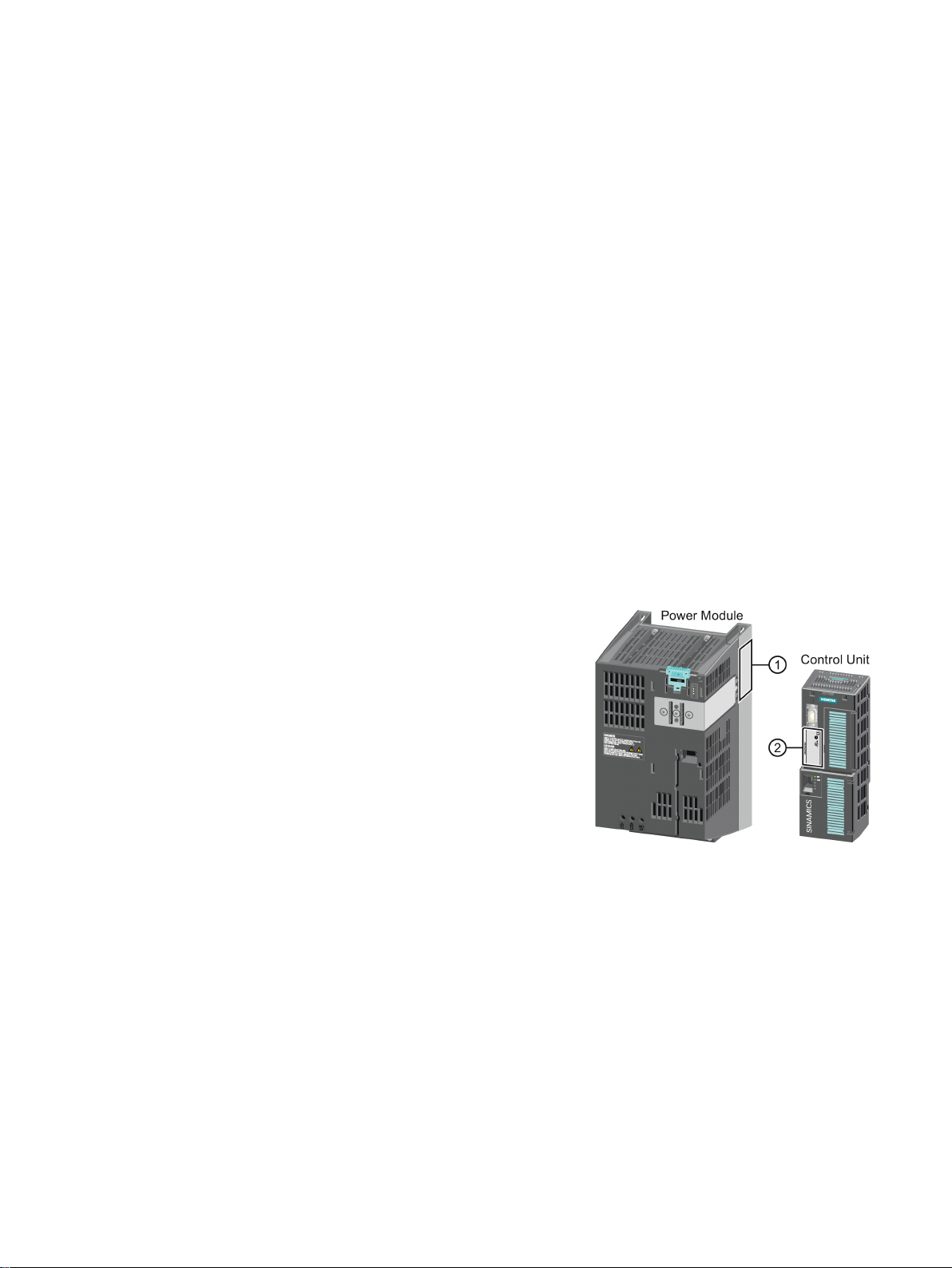
Main components of the inverter
Each SINAMICS G120 inverter comprise
trol Unit and a Power Module.
•
•
The following data is provided on the Power Module type plate (①
●
Designation:
e.g. Power Module 240
●
Technical data:
Voltage and current
●
Article number:
e. g. 6SL3224-0BE13-7UA0
●
Version:
e.g. A02
The following data can be found on the Control Unit type plate (②
●
Designation:
e.g. Control Unit CU240E-2 DP-F
●
Article number:
e.g. 6SL3244-0BB13-1PA0
●
Version:
e.g. A02 (hardware)
The inverter described in this manual is a device to control a three-phase motor. The inverter
is designed for installation in electrical installations or machines.
It has been approved for industrial and commercial use on industrial networks. Additional
measures have to be taken when connected to public grids.
The technical specifications and information about connection conditions are indicated on
the rating plate and in the operating instructions.
The Control Unit controls and monitors the
connected motor.
The Power Module provides the connections
for line supply and motor.
s a Con-
):
):
Converter with CU230P-2 Control Units
Operating Instructions, 04/2015, FW V4.7 SP3, A5E34257946B AB
25

Description
Further inverter components
3.1 Identifying the converter
The following components are available so that you can adapt the inverter to different
applications and ambient conditions:
● Line filter (Page 33)
● Line reactor (Page 34)
● Output reactor (Page 37)
● Sine-wave filter (Page 41)
● dv/dt filter (Page 42)
● Braking Module and braking resistor (Page 42)
● Basic Operator Panel 2 (BOP-2) (Page 46)
● Intelligent Operator Panel (IOP) (Page 46)
Converter with CU230P-2 Control Units
26 Operating Instructions, 04/2015, FW V4.7 SP3, A5E34257946B AB

Description
3.2
Control Units
Designation
Article number
Fieldbus
CU230P-2 HVAC
6SL3243-0BB30-1HA3
USS, Modbus RTU, BACnet MS/TP, P1
CU230P-2 PN
6SL3243-0BB30-1FA0
PROFINET IO, EtherNet/IP
CU230P-2 CAN
6SL3243-0BB30-1CA3
CANopen
1)
Exclusive version for Siemens IC BT
Memory cards
Scope of delivery
Article number
Memory card without firmware
6SL3054-4AG00-2AA0
Memory card with firmware V4.6
6SL3054-7EG00-2BA0
Memory card with firmware V4.7 SP3
6SL3054-7TB00-2BA0
Shield connection kit for the Control Unit
interfaces except for PROFINET.
with PROFINET interface.
3.2 Control Units
The Control Units differ with regard to the type of fieldbus.
CU230P-2 DP 6SL3243-0BB30-1PA3 PROFIBUS DP
CU230P-2 BT1) 6SL3243-6BB30-1HA3 USS, Modbus RTU, BACnet MS/TP, P1
Table 3- 1 Memory cards to back up inverter settings
Memory card with firmware V4.7 6SL3054-7EH00-2BA0
The shield connection kit is an optional component. The shield connection kit comprises the
following components:
● Shield plate
● Elements for optimum shield support and strain relief of the signal and communication
cables
Table 3- 2 Article Nos.
Shield connection kit 1 for the CU230P-2 Control Units with all fieldbus
Shield connection kit 3 for the CU230P-2 and CU240E-2 Control Units
6SL3264-1EA00-0FA0
6SL3264-1EA00-0HB0
Converter with CU230P-2 Control Units
Operating Instructions, 04/2015, FW V4.7 SP3, A5E34257946B AB
27
Description
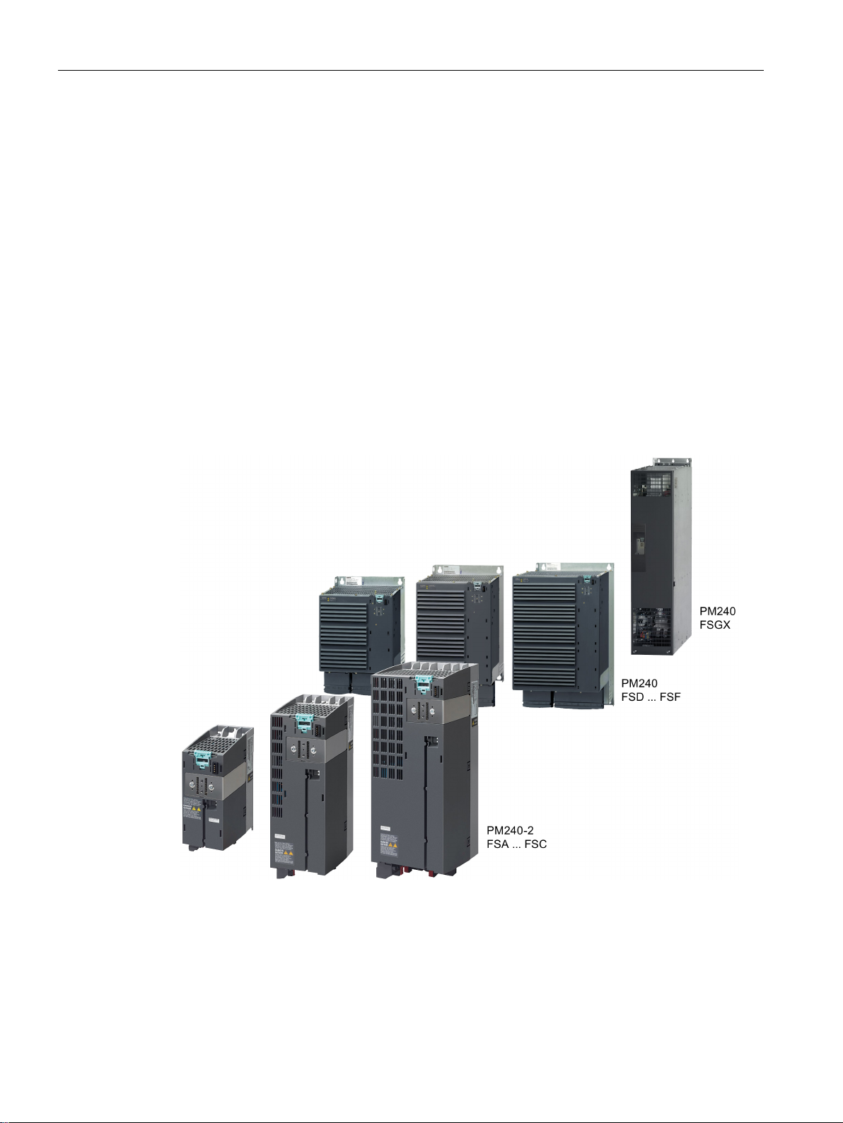
3.3
Power Module
Which Power Module can I use with the Control Unit?
•
•
•
•
•
•
3.3.1
Power Modules in degree of protection IP20 and with push-through system
3.3 Power Module
Important data on the Power Modules is provided in this section. Further information is
contained in the hardware installation manuals listed in Section Manuals for your inverter
(Page 451).
All power data refers to rated values or to power for operation with low overload (LO).
You can operate the CU230P-2 Control Unit with the following Power Modules:
PM230
PM330
PM240
PM240-2
PM250
PM260
Figure 3-1 Power Module with degree of protection IP20 examples
Converter with CU230P-2 Control Units
28 Operating Instructions, 04/2015, FW V4.7 SP3, A5E34257946B AB
Description
PM230, 3 AC 400 V - pump and fan applications
Article number range:
•
•
6SL3210
6SL3211
Frame size
FSA
FSB
FSC
FSD
FSE
FSF
Power range (kW), IP20
0.37 … 3
4 … 7.5
11 … 18.5
22 … 37
45 … 55
75 … 90
PM330, 3 AC 400 V - pump, fan and compressor applications
Frame size
GX
HX
Power range (kW)
160 … 250
315 … 400
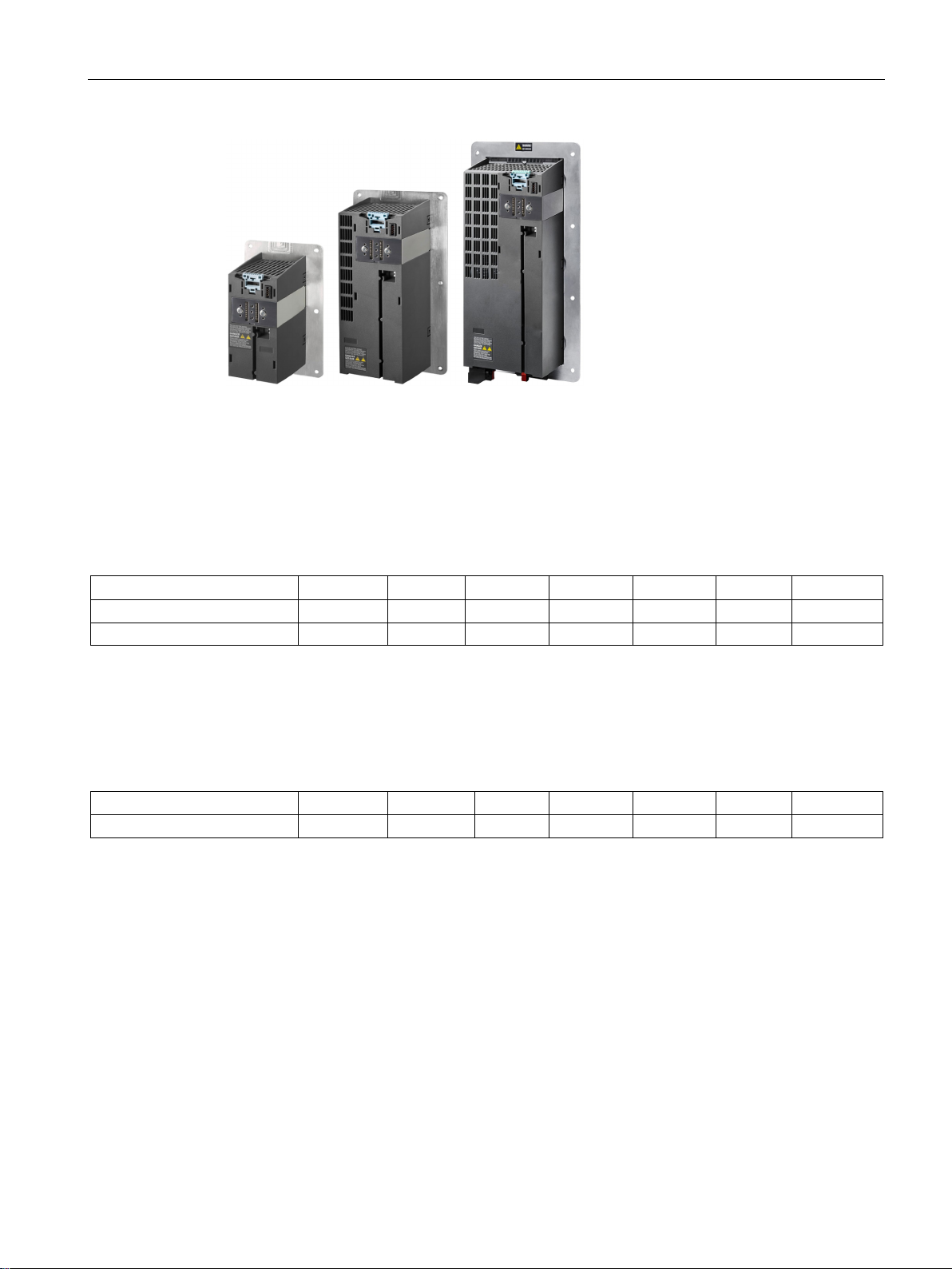
3.3 Power Module
Figure 3-2 Power Modules with the push-through system FSA … FSC
Power range (kW), PT 3 7.5 18.5 --- --- ---
The PM230 Power Module is available without a filter or with integrated class A line filter.
IP20:
Push Through:
-1NE…
-1NE…
The PM330 Power Module is available as an unfiltered device with IP20 degree of
protection. External line filters are available as an option, see Section
Article number range: 6SL3310-1PE…
Converter with CU230P-2 Control Units
Operating Instructions, 04/2015, FW V4.7 SP3, A5E34257946B AB
29

Description
PM240-2 - for standard applications
1 AC / 3 AC 200 V
Article number range:
•
6SL3210
•
6SL3211
Frame size
FSA
FSB FSC FSD FSE
Power range (kW), IP20
0.55 … 0.75
1.1 … 2.2
3.0 … 4.0
11 … 18.5
22 … 30
Power range (kW), PT
0.75
2.2
4.0
---
---
3 AC 400 V
Article number range:
•
6SL3210
•
6SL3211
Frame size
FSA
FSB FSC FSD FSE
Power range (kW), IP20
0.55 … 3.0
4.0 … 7.5
11 … 15
18.5 … 37
45 … 55
3 AC 600 V
Article number range:
•
6SL3210
•
6SL3211
Frame size
FSA
FSB
FSC
FSD
FSE
Power range (kW), IP20
---
---
---
11 … 37
45 … 55
Power range (kW), PT
---
---
---
---
---
PM240, 3 AC 400 V - for standard applications
Frame size
FSA
FSB
FSC
FSD
FSE
FSF
GX
Power range (kW)
0.37 … 1.5
2.2 … 4
7.5 … 15
18.5 … 30
37 … 45
55 … 132
160 … 250
3.3 Power Module
The PM240-2 Power Module is available without a filter or with an integrated class A line
filter. The PM240-2 permits dynamic braking via an external braking resistor.
Power range (kW), PT 3.0 7.5 15 --- ---
IP20:
Push Through:
IP20:
Push Through:
IP20:
Push Through:
-1PB…, 6SL3210-1PC…
-1PB…
-1PE…
-1PE…
-1PH…
-1PH…
Converter with CU230P-2 Control Units
30 Operating Instructions, 04/2015, FW V4.7 SP3, A5E34257946B AB
The PM240 Power Module is available without a filter or with an integrated class A line filter
with degree of protection IP20. The PM240 allows dynamic braking via an external braking
resistor.
Article number range: 6SL3224-0BE… and 6SL3224-0XE…
 Loading...