

Siemens SINAMICS G120P PM330 Installation Manuals


___________________
___________________
___________________
___________________
___________________
___________________
___________________
SINAMICS
SINAMICS G120P
Power Module PM330
Hardware Installation Manual
Closed-loop control version V4.7 SP6
10/2016
A5E32844552B AD
Basic safety instructions
1
Introduction
2
Installing/Mounting
3
Connecting up, switching on
4
Service and maintenance
5
Technical specifications
6
Appendix
A

Siemens AG
Division Process Industries and Drives
Postfach 48 48
90026 NÜRNBERG
GERMANY
A5E32844552B AD
Ⓟ
Copyright © Siemens AG 2013 - 2016.
All rights reserved
Legal information
Warning notice system
DANGER
indicates that death or severe personal injury will result if proper precautions are not taken.
WARNING
indicates that death or severe personal injury may result if proper precautions are not taken.
CAUTION
indicates that minor personal injury can result if proper precautions are not taken.
NOTICE
indicates that property damage can result if proper precautions are not taken.
Qualified Personnel
personnel qualified
Proper use of Siemens products
WARNING
Siemens products may only be used for the applications described in the catalog and in the relevant technical
ambient conditions must be complied with. The information in the relevant documentation must be observed.
Trademarks
Disclaimer of Liability
This manual contains notices you have to observe in order to ensure your personal safety, as well as to prevent
damage to property. The notices referring to your personal safety are highlighted in the manual by a safety alert
symbol, notices referring only to property damage have no safety alert symbol. These notices shown below are
graded according to the degree of danger.
If more than one degree of danger is present, the warning notice representing the highest degree of danger will
be used. A notice warning of injury to persons with a safety alert symbol may also include a warning relating to
property damage.
The product/system described in this documentation may be operated only by
task in accordance with the relevant documentation, in particular its warning notices and safety instructions.
Qualified personnel are those who, based on their training and experience, are capable of identifying risks and
avoiding potential hazards when working with these products/systems.
Note the following:
documentation. If products and components from other manufacturers are used, these must be recommended
or approved by Siemens. Proper transport, storage, installation, assembly, commissioning, operation and
maintenance are required to ensure that the products operate safely and without any problems. The permissible
All names identified by ® are registered trademarks of Siemens AG. The remaining trademarks in this publication
may be trademarks whose use by third parties for their own purposes could violate the rights of the owner.
We have reviewed the contents of this publication to ensure consistency with the hardware and software
described. Since variance cannot be precluded entirely, we cannot guarantee full consistency. However, the
information in this publication is reviewed regularly and any necessary corrections are included in subsequent
editions.
for the specific
10/2016 Subject to change

Table of contents
1 Basic safety instructions .......................................................................................................................... 7
2 Introduction ........................................................................................................................................... 15
3 Installing/Mounting ................................................................................................................................ 19
4 Connecting up, switching on .................................................................................................................. 29
1.1 General safety instructions ....................................................................................................... 7
1.2 Safety instructions for electromagnetic fields (EMF) .............................................................. 11
1.3 Handling electrostatic sensitive devices (ESD) ...................................................................... 11
1.4 Industrial security .................................................................................................................... 12
1.5 Residual risks of power drive systems .................................................................................... 13
3.1 Installation conditions.............................................................................................................. 19
3.2 Power losses and air cooling requirements ............................................................................ 20
3.3 Mounting the Power Modules ................................................................................................. 22
3.3.1 Chassis units ........................................................................................................................... 25
3.4 Control Unit installation ........................................................................................................... 28
4.1 Cable lugs ............................................................................................................................... 30
4.2 Line, motor and DC link connection ........................................................................................ 31
4.2.1 Protective conductor ............................................................................................................... 31
4.2.2 Line connection ....................................................................................................................... 32
4.2.3 Length of motor cables ........................................................................................................... 32
4.2.4 Motor connection .................................................................................................................... 33
4.2.5 Access to power and motor terminals ..................................................................................... 34
4.2.6 DC link connection .................................................................................................................. 38
4.3 Operation on a non-grounded line supply (IT system) ........................................................... 39
4.4 Installation set for line-side cable connection, left .................................................................. 41
4.5 Terminal X9 ............................................................................................................................. 47
4.6 EMC compliant connection ..................................................................................................... 49
4.6.1 Avoiding electromagnetic interference .................................................................................... 49
4.6.2 EMC-compliant cabinet design ............................................................................................... 49
4.6.3 Cabinet design ........................................................................................................................ 50
4.6.4 Cabling .................................................................................................................................... 51
4.6.5 Equipotential bonding ............................................................................................................. 53
4.7 Switching on ............................................................................................................................ 56
Power Module PM330
Hardware Installation Manual, 10/2016, A5E32844552B AD
5

Table of contents
5 Service and maintenance ...................................................................................................................... 57
6 Technical specifications ........................................................................................................................ 65
A Appendix .............................................................................................................................................. 87
Index .................................................................................................................................................... 95
5.1 Maintenance ........................................................................................................................... 57
5.2 Forming .................................................................................................................................. 59
5.3 Replacing the cooling fan ....................................................................................................... 61
5.3.1 Service life of the cooling fan ................................................................................................. 61
5.3.2 Fan replacement GX .............................................................................................................. 61
5.3.3 Fan replacement for HX, JX ................................................................................................... 63
6.1 General technical data ........................................................................................................... 66
6.2 Specific technical data ........................................................................................................... 70
6.3 Derating data .......................................................................................................................... 82
6.3.1 Derating factor of the output current as a function of the operating temperature .................. 82
6.3.2 Derating as a function of the installation altitude ................................................................... 83
6.3.3 Derating factor of the output current as a function of the line voltage ................................... 84
6.3.4 Derating of the output current as a function of the pulse frequency ...................................... 85
A.1 Further information on your converter ................................................................................... 87
A.1.1 Manuals for your inverter ....................................................................................................... 87
A.1.2 Configuring support ................................................................................................................ 88
A.1.3 Product Support ..................................................................................................................... 88
A.1.4 Certificates ............................................................................................................................. 89
A.2 Electromagnetic compatibility ................................................................................................ 89
A.2.1 Definition of the EMC Environment and Categories .............................................................. 89
A.2.2 Compliance with EMC Environment and Categories ............................................................. 90
A.2.3 EMC limit values in South Korea ........................................................................................... 92
A.3 Abbreviations ......................................................................................................................... 93
Power Module PM330
6 Hardware Installation Manual, 10/2016, A5E32844552B AD
1
1.1
General safety instructions
DANGER
Danger to life due to live parts and other energy sources
WARNING
Danger to life through a hazardous voltage when connecting an unsuitable power supply
Touching live parts can result in death or severe injury.
• Only work on electrical equipment if you are appropriately qualified.
• Always observe the country-specific safety rules for all work.
Generally, six steps apply when establishing safety:
1. Prepare for shutdown and notify all those who will be affected by the procedure.
2. Disconnect the machine from the supply.
– Switch off the machine.
– Wait until the discharge time specified on the warning labels has elapsed.
– Check that it really is in a zero-voltage state, from phase conductor to phase
conductor and phase conductor to protective conductor.
– Check that every auxiliary circuit is de-energized.
– Ensure that the motors cannot move.
3. Identify all other dangerous energy sources, e.g. compressed air, hydraulic systems, or
water.
4. Isolate or neutralize all hazardous energy sources by closing switches, grounding or
short-circuiting or closing valves, for example.
5. Take measures to prevent reconnection of the energy sources.
6. Ensure that the correct machine is completely interlocked.
After you have completed the work, restore the operational readiness by following the
above steps in the reverse order.
In the event of a fault, touching live parts can result in death or severe injury.
• Only use power supplies that provide SELV (Safety Extra Low Voltage) or PELV
(Protective Extra Low Voltage) output voltages for all connections and terminals of the
electronics modules.
Power Module PM330
Hardware Installation Manual, 10/2016, A5E32844552B AD
7
Basic safety instructions
WARNING
Danger to life when live parts are touched on damaged devices
WARNING
Danger to life through electric shock due to unconnected cable shields
WARNING
Danger to life due to electric shock when not grounded
WARNING
Danger to life due to electric shock when opening plug connections in operation
NOTICE
Material damage due to loose power connections
1.1 General safety instructions
Improper handling of devices can cause damage.
For damaged devices, hazardous voltages can be present at the enclosure or at exposed
components; if touched, this can result in death or severe injury.
• Ensure compliance with the limit values specified in the technical data during transport,
storage and operation.
• Do not use any damaged devices.
Hazardous touch voltages can occur through capacitive cross-coupling due to unconnected
cable shields.
• Connect cable shields and unused conductors of power cables (e.g. brake conductors)
at least on one side to the grounded housing potential.
For missing or incorrectly implemented protective conductor connection for devices with
protection class I, high voltages can be present at open, exposed parts, which when
touched, can result in death or severe injury.
• Ground the device in compliance with the applicable regulations.
When opening plug connections in operation, arcs can result in severe injury or death.
• Only open plug connections when the equipment is in a voltage-free state, unless it has
been explicitly stated that they can be opened in operation.
Insufficient tightening torques or vibrations can result in loose electrical connections. This
can result in damage due to fire, device defects, or malfunctions.
• Tighten all power connections with the specified tightening torques, e.g. line connection,
motor connection, DC link connections.
• Check all power connections at regular intervals. This applies in particular after
transport.
Power Module PM330
8 Hardware Installation Manual, 10/2016, A5E32844552B AD

Basic safety instructions
WARNING
Danger to life due to fire spreading if housing is inadequate
WARNING
Danger to life through unexpected movement of machines when using mobile wireless
devices or mobile phones
WARNING
Danger to life due to the motor catching fire in the event of insulation overload
WARNING
Danger to life due to fire if overheating occurs because of insufficient ventilation clearances
1.1 General safety instructions
Fire and smoke development can cause severe personal injury or material damage.
• Install devices without a protective enclosure in a metal control cabinet (or protect the
device by another equivalent measure) in such a way that contact with fire is prevented.
• Ensure that smoke can only escape via controlled and monitored paths.
Using mobile radios or mobile phones with a transmit power > 1 W closer than approx. 2 m
to the components may cause the devices to malfunction, influence the functional safety of
machines therefore putting people at risk or causing material damage.
• When close to components, switch off all wireless devices and mobile phones.
There is a greater load on the motor insulation through a ground fault in an IT system. If the
insulation fails, it is possible that death or severe injury can occur as a result of smoke and
fire.
• Use a monitoring device that signals an insulation fault.
• Correct the fault as quickly as possible so the motor insulation is not overloaded.
Inadequate ventilation clearances can cause overheating of components with subsequent
fire and smoke. This can cause severe injury or even death. This can also result in
increased downtime and reduced service lives for devices/systems.
• Ensure compliance with the specified minimum clearance as ventilation clearance for
the respective component.
Power Module PM330
Hardware Installation Manual, 10/2016, A5E32844552B AD
9

Basic safety instructions
WARNING
Danger of an accident occurring due to missing or illegible warning labels
NOTICE
Device damage caused by incorrect voltage/insulation tests
WARNING
Danger to life due to inactive safety functions
1.1 General safety instructions
Missing or illegible warning labels can result in accidents involving death or serious injury.
• Check that the warning labels are complete based on the documentation.
• Attach any missing warning labels to the components, in the national language if
necessary.
• Replace illegible warning labels.
Incorrect voltage/insulation tests can damage the device.
• Before carrying out a voltage/insulation check of the system/machine, disconnect the
devices as all converters and motors have been subject to a high voltage test by the
manufacturer, and therefore it is not necessary to perform an additional test within the
system/machine.
Inactive or non-adapted safety functions can trigger machine malfunctions that can cause
serious injury or death.
• Observe the information in the appropriate product documentation before
commissioning.
• Carry out a safety inspection for functions relevant to safety on the entire system,
including all safety-related components.
• Ensure that the safety functions used in your drives and automation tasks are adjusted
and activated through appropriate parameterizing.
• Perform a function test.
• Only put your plant into productive operation once you have absolutely guaranteed that
the functions relevant to safety are operating correctly.
Power Module PM330
10 Hardware Installation Manual, 10/2016, A5E32844552B AD
Basic safety instructions
1.2
Safety instructions for electromagnetic fields (EMF)
WARNING
Danger to life from electromagnetic fields
1.3
Handling electrostatic sensitive devices (ESD)
NOTICE
Damage caused by electric fields or electrostatic discharge
1.2 Safety instructions for electromagnetic fields (EMF)
Electromagnetic fields (EMF) are generated by the operation of electrical power equipment
such as transformers, converters or motors.
People with pacemakers or implants are at a special risk in the immediate vicinity of these
devices/systems.
• Ensure that the persons involved are the necessary distance away (minimum 2 m).
Electrostatic sensitive devices (ESDs) are individual components, integrated circuits,
modules or devices that may be damaged by either electrostatic fields or electrostatic
discharge.
Electric fields or electrostatic discharge can result in malfunctions as a result of damaged
individual parts, integrated circuits, modules or devices.
• Only pack, store, transport and send electronic components, modules or devices in their
original packaging or in other suitable materials, e.g conductive foam rubber of
aluminum foil.
• Only touch components, modules and devices if you are first grounded by applying one
of the following measures:
– Wearing an ESD wrist strap
– Wearing ESD shoes or ESD grounding straps in ESD areas with conductive flooring
• Only place electronic components, modules or devices on conductive surfaces (table
with ESD surface, conductive ESD foam, ESD packaging, ESD transport container).
Power Module PM330
Hardware Installation Manual, 10/2016, A5E32844552B AD
11

Basic safety instructions
1.4
Industrial security
Note
Industrial security
Siemens provides products and solutions with industrial security functions that support the
secure operation of plants, systems, machines and networ
In order to protect plants, systems, machines and networks against cyber threats, it is
necessary to implement
security concept. Siemens products and solutions only represent one com
concept.
The customer is responsible for preventing unauthorized access to its plants, systems,
machines and networks. Systems, machines and components should only be connected to
the enterprise network or the internet if and to the extent
security measures (e.g. use of firewalls and network segmentation) in place.
Additionally, Siemens’ guidance on appropriate security measures should be taken into
account. For more information about industrial security, ple
Industrial security (
Siemens’ products and solutions undergo continuous development to make them more
secure. Siemens strongly recommends to
always use the latest product versions. Use of product versions that are no longer supported,
and failure to apply latest updates may increase customer’s exposure to cyber threats.
To stay informed about p
Feed at:
Industrial security (http://www.siemens.com/industrialsecurity).
WARNING
Danger to life as a result of unsafe operating states resulting from software manipulation
Note
Industrial security Configuration Manual
You can find a Configuration Manual on the topic of industrial security at this address
(
1.4 Industrial security
ks.
– and continuously maintain – a holistic, state-of-the-art industrial
ponent of such a
necessary and with appropriate
ase visit:
http://www.siemens.com/industrialsecurity).
apply product updates as soon as available and to
roduct updates, subscribe to the Siemens Industrial Security RSS
Software manipulations (e.g. viruses, trojans, malware or worms) can cause unsafe
operating states in your system that may lead to death, serious injury, and property
damage.
• Keep the software up to date.
• Incorporate the automation and drive components into a state-of-the-art, integrated
industrial security concept for the installation or machine.
• Make sure that you include all installed products into the integrated industrial security
concept.
• Protect files stored on exchangeable storage media from malicious software by with
suitable protection measures, e.g. virus scanners.
https://support.industry.siemens.com/cs/ww/en/view/108862708).
Power Module PM330
12 Hardware Installation Manual, 10/2016, A5E32844552B AD

Basic safety instructions
1.5
Residual risks of power drive systems
1.5 Residual risks of power drive systems
When assessing the machine- or system-related risk in accordance with the respective local
regulations (e.g. EC Machinery Directive), the machine manufacturer or system installer
must take into account the following residual risks emanating from the control and drive
components of a drive system:
1. Uncontrolled motion of the driven machine or system components during commissioning,
operation, maintenance and repair caused by, for example:
– Hardware and/or software errors in the sensors, control system, actuators and cables
and connections
– Response times of the controller and drive
– Operation and/or environmental conditions outside the specification
– Condensation/conductive pollution
– Parameterization, programming, cabling, and installation errors
– Use of wireless devices/mobile phones in the immediate vicinity of electronic
components
– External influence/damage
– X-ray, ionizing radiation and cosmic radiation
2. Unusually high temperatures - including open flames - as well as the emission of light,
noise, particles, gases, etc. can occur inside and outside the components under fault
conditions caused by, for example:
– Component malfunctions
– Software errors
– Operation and/or environmental conditions outside the specification
– External influence/damage
3. Hazardous shock voltages caused by, for example:
– Component malfunctions
– Influence of electrostatic charging
– Induction of voltages in moving motors
– Operation and/or environmental conditions outside the specification
– Condensation/conductive pollution
– External influence/damage
4. Electrical, magnetic and electromagnetic fields generated in operation that can pose a
risk to people with a pacemaker, implants or metal replacement joints, etc. if they are too
close.
5. Release of environmental pollutants or emissions as a result of improper operation of the
system and/or failure to dispose of components safely and correctly
6. Influence of network-connected communication systems, e.g. ripple-control transmitters
or data communication via the network
For more information about the residual risks of the drive system components, see the
relevant sections in the technical user documentation.
Power Module PM330
Hardware Installation Manual, 10/2016, A5E32844552B AD
13

Basic safety instructions
1.5 Residual risks of power drive systems
Power Module PM330
14 Hardware Installation Manual, 10/2016, A5E32844552B AD

2
Power Module - PM330
The PM330 Power Module is a part of the modular family of SINAMICS G120 converters.
PM330 Power Modules have been specifically optimized for driving pumps, fans, blowers
and compressors with square-law load characteristic for use in HVAC applications. The
Power Module is available with the "internal air cooling" cooling method.
The Power Modules are available for the following rated voltages and rated powers:
● 3 AC 380 V … 480 V: 160 kW … 560 kW
● 3 AC 500 V … 690 V: 315 kW … 630 kW
The Power Modules can be connected to the following line supply systems:
● TN system
● TT system
● IT system
690-V line supplies with grounded line conductor are not permitted.
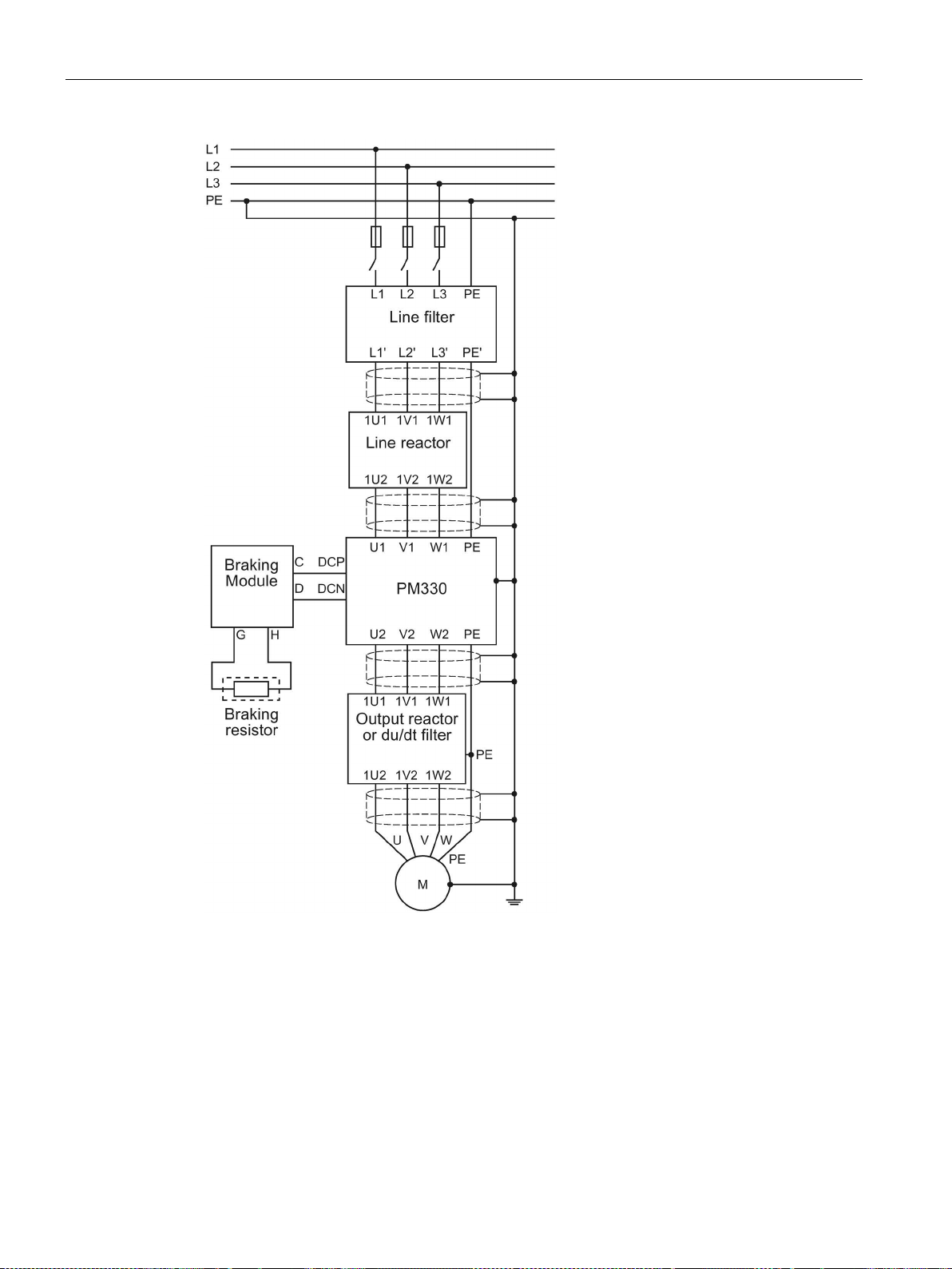
As standard, a line reactor (u
diagram).
≥ 2 %) must be provided at the line input (see the following
k
Power Module PM330
Hardware Installation Manual, 10/2016, A5E32844552B AD
15
Introduction
Figure 2-1 PM330 block diagram
Power Module PM330
16 Hardware Installation Manual, 10/2016, A5E32844552B AD

Introduction
Note
Principle of the precharging circuit
SINAMICS PM330 Power Modules include a half
circuit. As a result of the precharging principle with phase control, precharging is only started
when all of the enable signals are available and by setting the ON/OFF co
(p0840
The DC link is then fully charged after approximately 400
•
6SL3243
•
6SL3243
•
6SL3243
-controlled thyristor bridge as rectifier
mmand
= 1).
ms.
The Power Modules can be used with the following Control Units, including all
communication versions with firmware version from 4.6 HF7 and higher.
CU230P-2 PN
-0BB30-1FAx
CU230P-2 DP
CU230P-2 HVAC
-0BB30-1PAx
-0BB30-1HAx
Operation with Control Units other than those listed above is not permitted.
Power Module PM330
Hardware Installation Manual, 10/2016, A5E32844552B AD
17

Introduction
Power Module PM330
18 Hardware Installation Manual, 10/2016, A5E32844552B AD

3
3.1
Installation conditions
Unpacking and disposal
Note
The c
The individual components of the packaging can be recycled or disposed of in compliance
with local regulations.
General rules for protecting Power Modules against environmental effects
onverter packaging can be reused.
To ensure that the Power Module is installed in the correct environmental conditions, please
make sure that you adhere to the following guidelines:
● The Power Modules are designed:
– to be installed in an electrical cabinet
– with protection against the ingress of solid foreign objects ≥ 12.5 mm
– without protection against the ingress of water
● Furthermore, observe the following conditions:
– Ensure that the device is free of dust and dirt.
(when using a vacuum cleaner, this must comply with ESD equipment rules)
– Keep the device away from water, solvents and chemicals.
Take care to install it away from potential water hazards, for example, do not install it
beneath pipes that are subject to condensation. Avoid installing it where excessive
humidity and condensation may occur.
– Keep it within the maximum and minimum operating temperatures.
– Ensure that the correct level of ventilation and air flow is provided.
– Fast temperature changes of the air drawn in (e.g. by using cooling units) are not
permitted due to the danger of condensation. Condensation is not permissible when
switching on.
– Ensure that all Power Modules and the cabinet are grounded according to the
guidelines given in this chapter (see Chapter Connecting up, switching on (Page 29)).
It is only permissible that the Power Module is installed in a vertical position.
Power Module PM330
Hardware Installation Manual, 10/2016, A5E32844552B AD
19

Installing/Mounting
WARNING
Danger to life due to voltage
Protection against the spread of fire
Protection against condensation or electrically conductive pollution
3.2
Power losses and air cooling requirements
General requirement
3.2 Power losses and air cooling requirements
To ensure safe operation of the equipment, it must be installed and commissioned by
qualified personnel in full compliance with the warnings laid down in this manual.
It is especially important to comply with general and local installation and safety regulations
for working on plants and systems with hazardous voltages (e.g. EN 61800-5-1) - as well as
the relevant regulations regarding the correct use of tools and personal protective
equipment (PPE).
The device may only be operated in closed housings or in control cabinets with protective
covers that are closed, and when all of the protective devices are used. The installation of
the device in a metal control cabinet or the protection with another equivalent measure must
prevent the spread of fire and emissions outside the control cabinet.
Protect the device, e.g. by installing it in a control cabinet with degree of protection IP54
according to IEC 60529 or NEMA 12. Further measures may be necessary for particularly
critical operating conditions.
If condensation or conductive pollution can be excluded at the installation site, a lower
degree of control cabinet protection is permitted.
Installation in the cabinet and the cooling must guarantee that the air temperature - under all
operating conditions and all possible cabinet equipment configurations - inside the Power
Module at the top in the area of the rectifier modules is a maximum of 65 °C - and the air
intake below the Control Unit (behind the left hand housing flap) is a maximum of 60 °C.
Power Module PM330
20 Hardware Installation Manual, 10/2016, A5E32844552B AD
Installing/Mounting
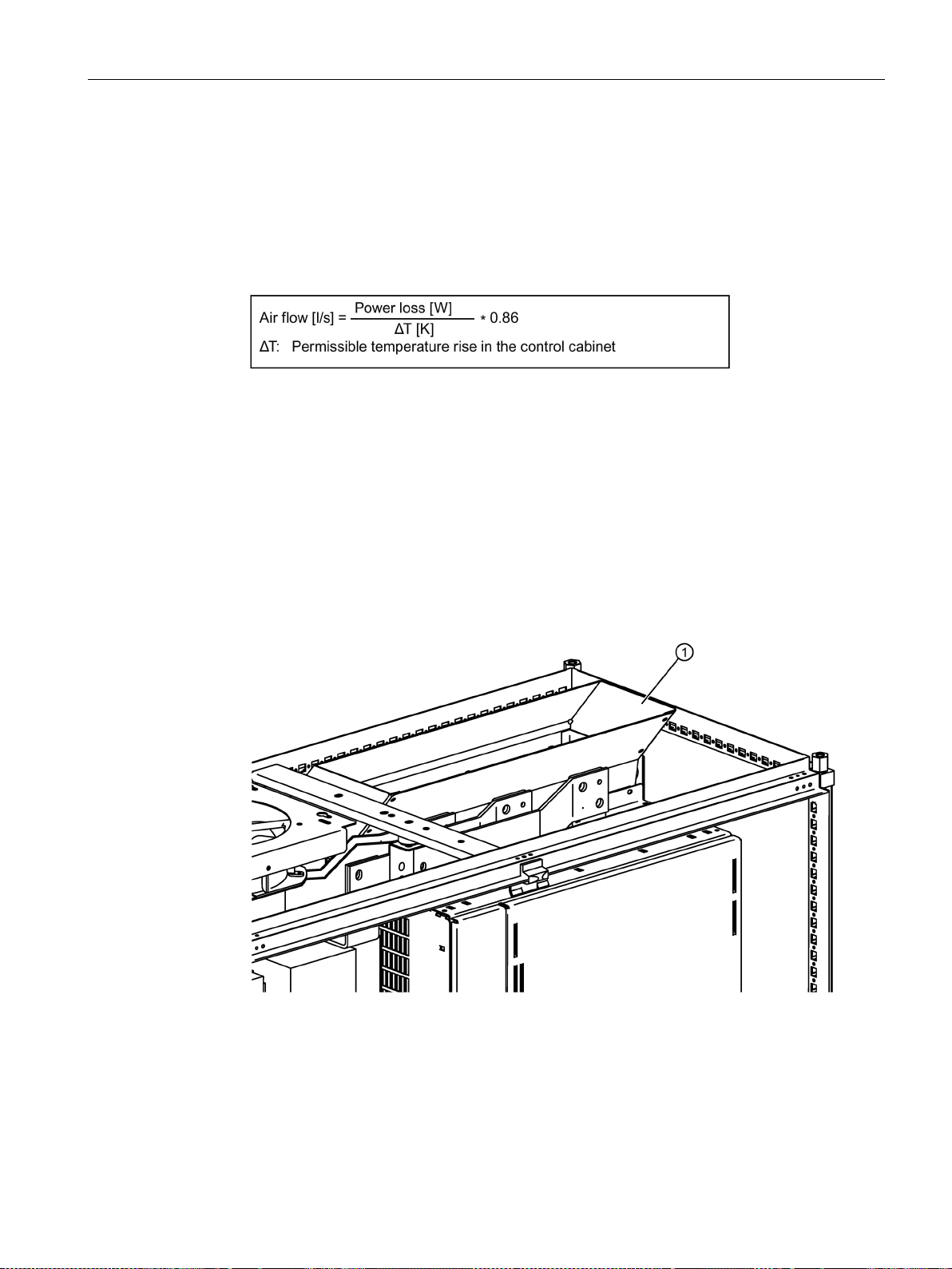
Cooling requirements
3.2 Power losses and air cooling requirements
Depending on the power losses of the various components a specific cooling air flow is
required to protect the components from overheating. The following equation shows you how
to calculate the required air flow.
1. Add the power losses of the individual components.
2. Calculate the air flow required, using the formula.
3. Ensure that the air intake and air discharge openings are adequately large so that the
pressure drop in the cabinet at the required cooling air flow rate (for the Power Modules,
see Specific technical data (Page 70)) remains ≤100 Pa, even when filter mats are used.
4. Ensure that no equipment is mounted that has a negative impact on the cooling air flow.
5. Ensure that the air openings in the Power Modules are free so that the airflow is not
obstructed (for the necessary clearances, see Chassis units (Page 25)).
6. Avoid possible short-circuits in the airflow (= air circulates within the cabinet) by using the
appropriate partitions, e.g. by using an air discharge duct up to the roof panel (see
position
① in the following diagram).
When converter cabinets are lined up next to one another, then these cabinets must be
separated from the adjacent cabinets using intermediate walls or panels.
Figure 3-1 Example of an air discharge duct
Power Module PM330
Hardware Installation Manual, 10/2016, A5E32844552B AD
21

Installing/Mounting
3.3
Mounting the Power Modules
WARNING
Danger to life if the fundamental safety instructions and remaining risks are not carefully
observed
Note
EMC
•
3.3 Mounting the Power Modules
7. Ensure that the electrical cabinet is adequately ventilated and is equipped with suitable
air filters.
It is crucial that you comply with the replacement intervals of the air filter (see also
Chapter Service and maintenance (Page 57).
The power losses and the required cooling airflow of the Power Modules are specified in
Chapter Specific technical data (Page 70).
The values are valid for:
● Rated output current
● 50 Hz output frequency
● 2 kHz pulse frequency
The non-observance of the fundamental safety instructions and residual risks stated in
Chapter Basic safety instructions (Page 7) can result in accidents with severe injuries or
death.
• Adhere to the fundamental safety instructions.
• When assessing the risk, take into account residual risks.
The Power Modules are designed to be mounted in accordance with the dimension
drawings, in a cabinet using screws, nuts and washers.
To comply with EMC specifications, it is recommended to mount the converter on an
electrically conductive mounting panel in the cabinet. This mounting panel should be
connected to the cabinet PE.
Power Module PM330
22 Hardware Installation Manual, 10/2016, A5E32844552B AD
Installing/Mounting
Note
Fixing elements used
The following fixing elements are used:
•
•
Tightening torques:
•
•
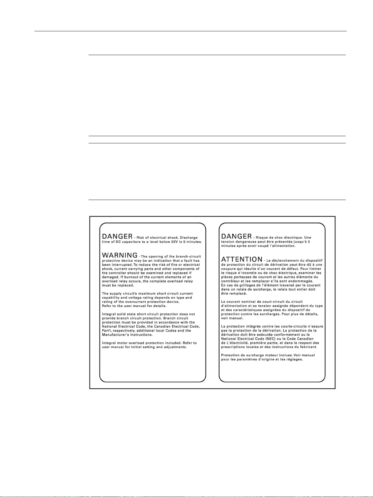
Note
Adhesive label with danger and warning notes in English and French
The adhesive label with danger and warning notes in English and French subseque
shown is included with the converter.
•
3.3 Mounting the Power Modules
M8 screw
Washer according to DIN EN ISO 7093-1 and locking element
electrical connections 50 Nm ±15 % (M12 bolts)
mechanical screw connections: 25 Nm ±15 % (M8 bolts)
ntly
Attach the adhesive label in the appropriate language to the inside of the converter
cabinet, where it is clearly visible at all times.
Figure 3-2 Adhesive label with danger and warning notes
Power Module PM330
Hardware Installation Manual, 10/2016, A5E32844552B AD
23
Installing/Mounting
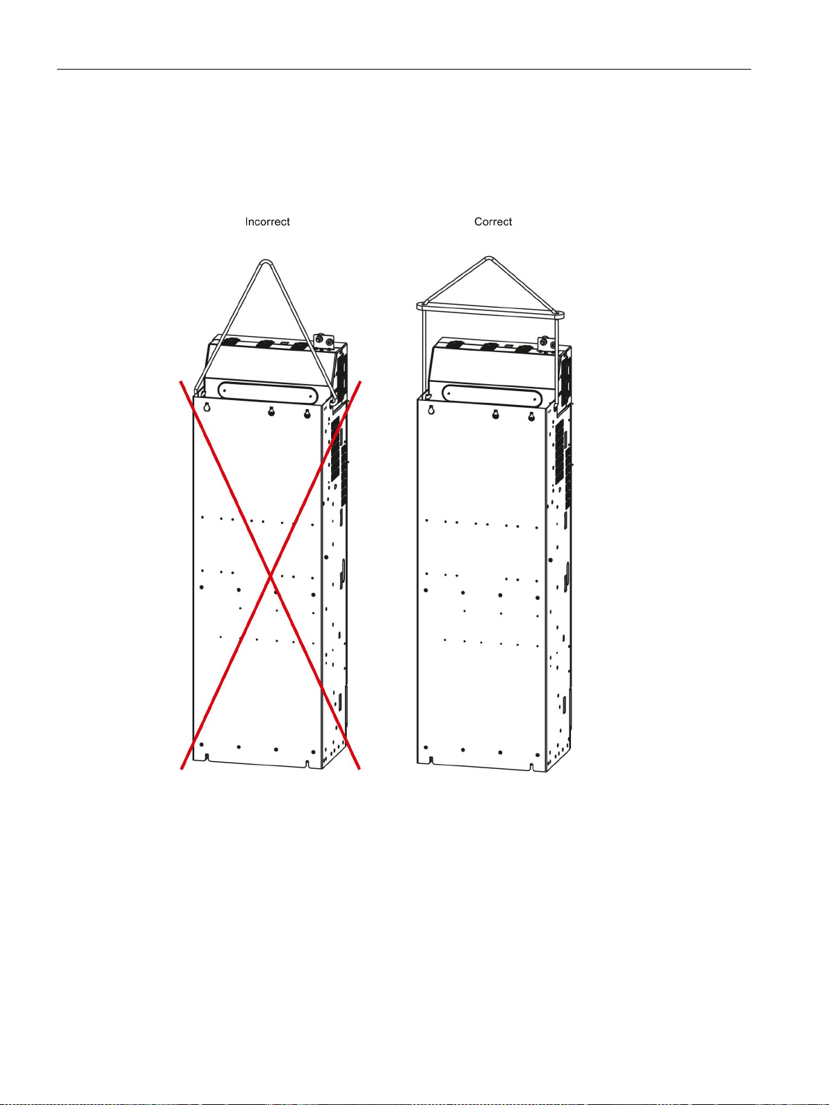
Lifting Power Modules
3.3 Mounting the Power Modules
The Power Modules can be lifted using the lifting eyebolts provided. Use a lifting harness
where the ropes or chains are maintained in a vertical position. The device must not be lifted
at an angle because this can damage the housing. Rope spreaders may have to be used.
Figure 3-3 Lifting Power Modules
Power Module PM330
24 Hardware Installation Manual, 10/2016, A5E32844552B AD
Installing/Mounting
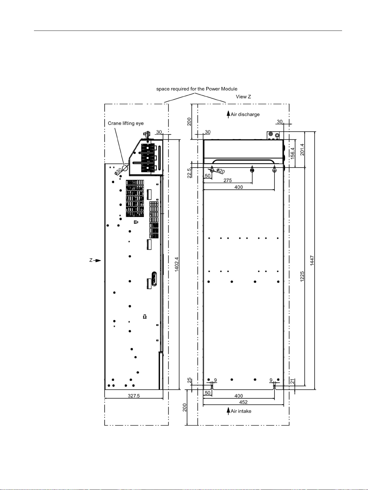
3.3.1
Chassis units
Drilling patterns, dimensions and clearances
3.3 Mounting the Power Modules
Figure 3-4 Dimension drawing of PM330 frame size GX, view from the side, view from the rear
Power Module PM330
Hardware Installation Manual, 10/2016, A5E32844552B AD
25
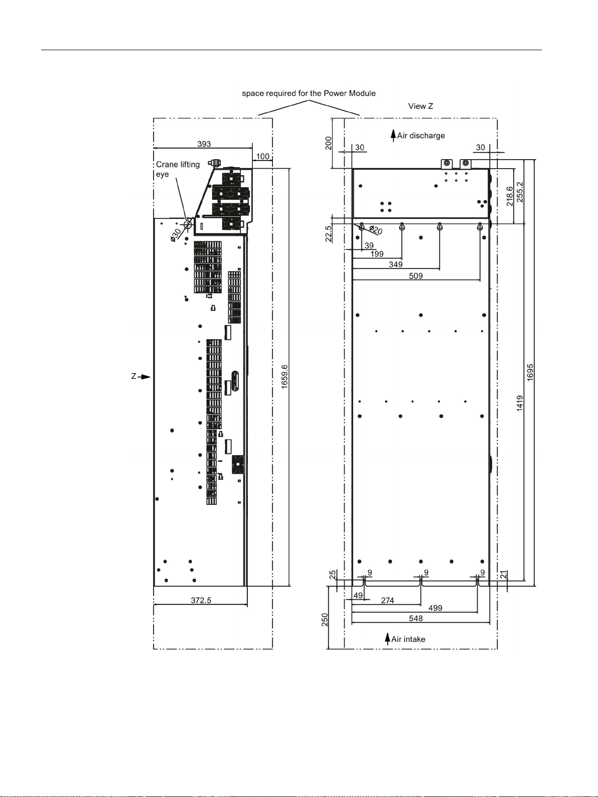
Installing/Mounting
3.3 Mounting the Power Modules
Figure 3-5 Dimension drawing of PM330 frame size HX, view from the side, view from the rear
Power Module PM330
26 Hardware Installation Manual, 10/2016, A5E32844552B AD
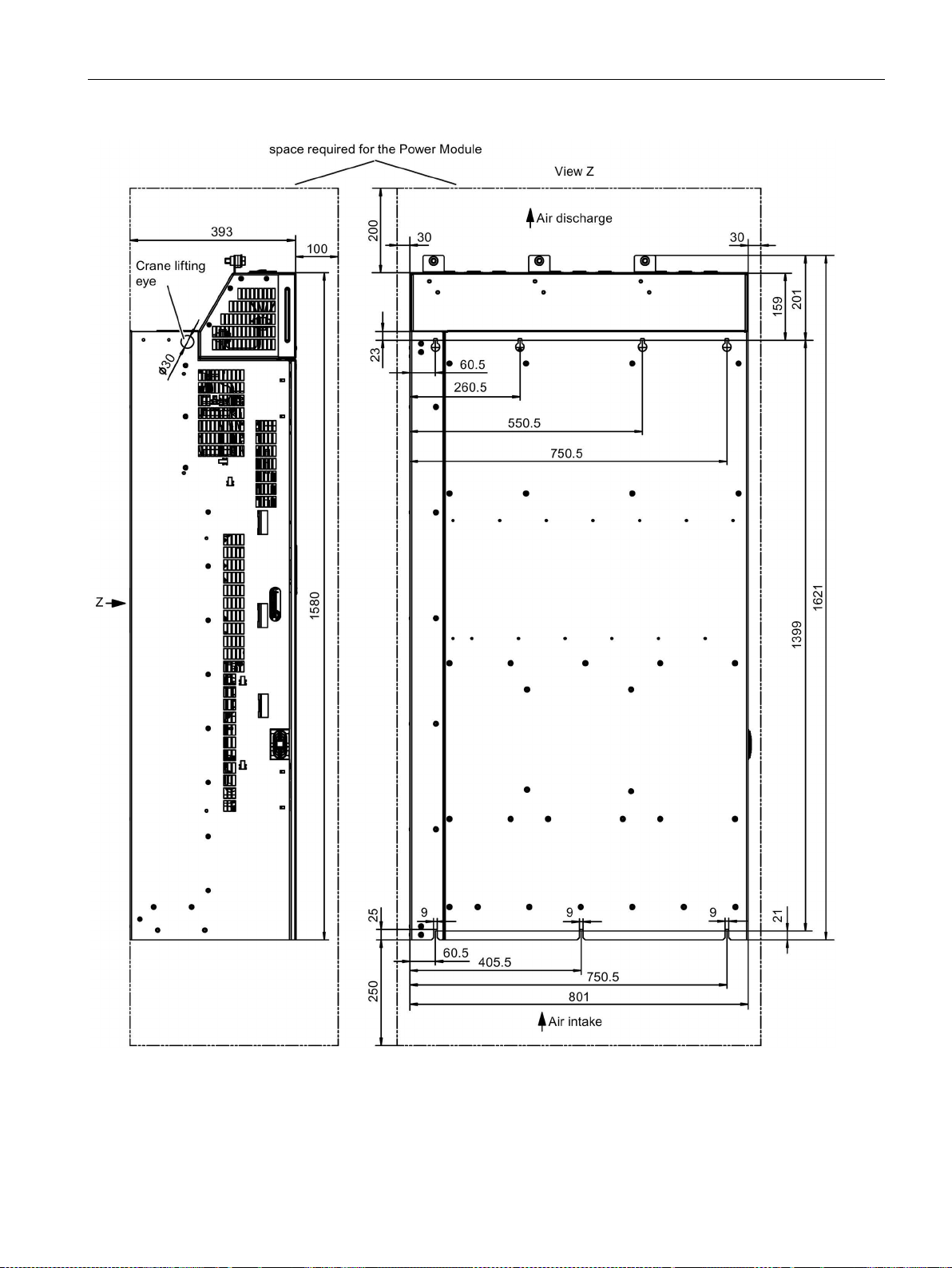
Installing/Mounting
3.3 Mounting the Power Modules
Figure 3-6 Dimension drawing of PM330 frame size JX, view from the side, view from the rear
Power Module PM330
Hardware Installation Manual, 10/2016, A5E32844552B AD
27
Installing/Mounting
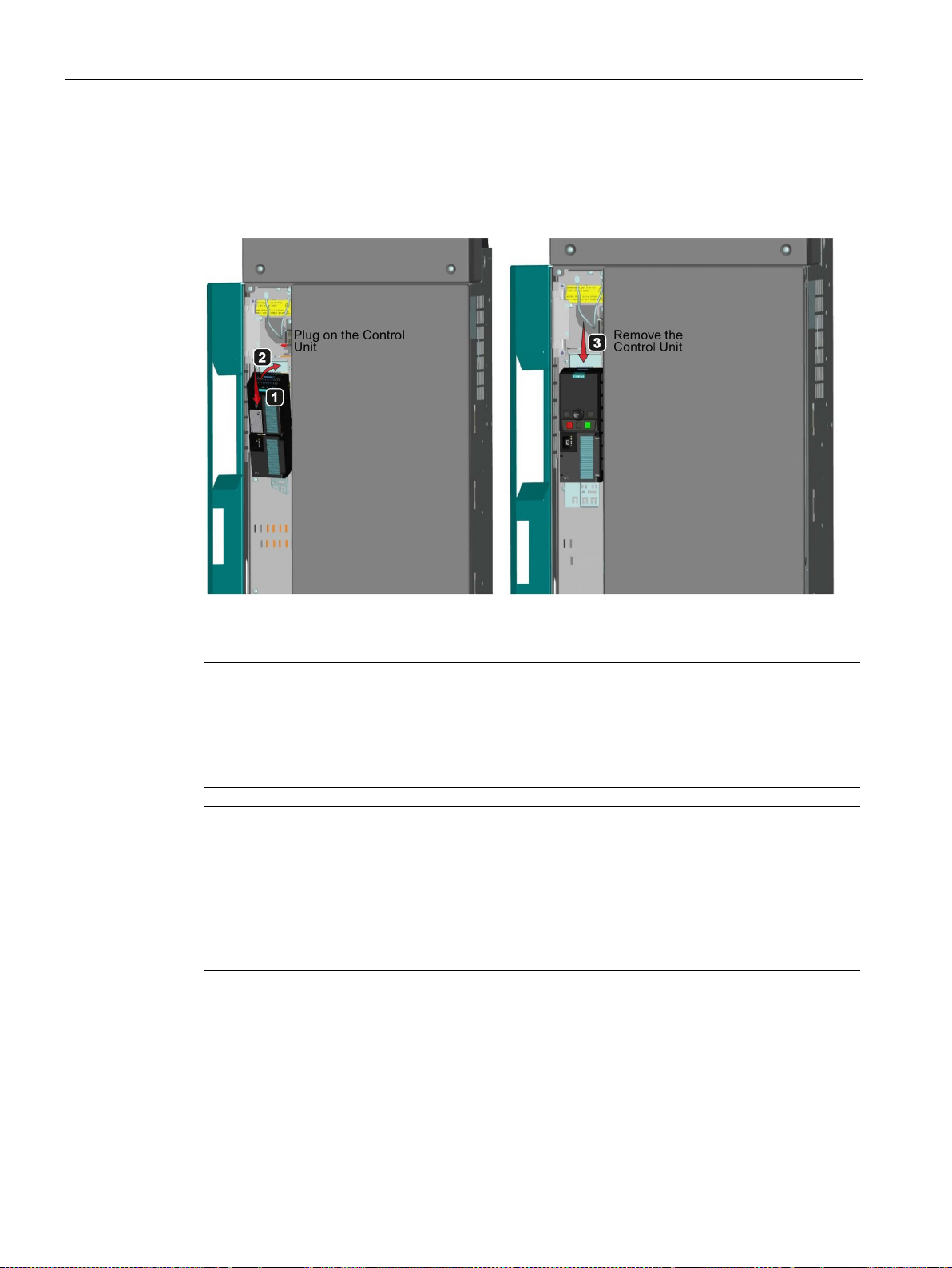
3.4
Control Unit installation
Note
Failure of the Control Unit as a result of overheating when the housing flap is open.
Adequate cooling of the Control Unit is not guaranteed when the housing flap is open. As a
consequence, when the converter is operational, the Control Unit can overheat and t
•
Note
Failure of the Control Unit as a result of overheating due to the fact that the cooling openings
are covered over.
Adequate cooling of the Control Unit is not guaranteed when the
right
is operational, the Control Unit can overheat and thus fail.
•
3.4 Control Unit installation
After opening the left-hand housing flap, the Control Unit is plugged onto the Power Module.
To remove the Control Unit, press the blue release knob at the top of the Control Unit.
Figure 3-7 Mounting and removing the Control Unit
hus fail.
Close the housing flap when the converter is operational.
cooling openings on the
-hand side of the Control Unit are covered over. As a consequence, when the converter
Do not cover over the cooling openings on the right-hand side of the Control Unit.
Power Module PM330
28 Hardware Installation Manual, 10/2016, A5E32844552B AD
4
Preconditions
DANGER
Danger to life through electric shock due to the residual charge of the DC link capacitors
WARNING
Danger of an accident due to missing warning labels in the national language.
NOTICE
Converter damaged due to overvoltage
Note
Ensure that the appropriate circuit breakers or fuses with the specified current rating are
connected between the power supply and the drive. The technical data contain information
about the circuit breaker and
Line and motor connections can be established once the converter has been properly
installed. It is crucial that the following notes are observed.
Because of the DC link capacitors, a hazardous voltage is present for up to five minutes
after the power supply has been switched off.
Contact with live parts can result in death or serious injury.
• Only open the device after five minutes have elapsed.
• Measure the voltage before starting work on the DCP and DCN DC link terminals.
Missing warning labels in the national language can result in death or serious injury.
• Attach the component warning labels in the national language.
Line-side overvoltages can damage the converter.
• Install the surge voltage protection device directly at the infeed point (before the main
switch).
fuses (see Specifications).
Power Module PM330
Hardware Installation Manual, 10/2016, A5E32844552B AD
29

Connecting up, switching on
4.1
Cable lugs
Cable lugs
Screw / bolts
Connection cross-section
[mm²]
d2
[mm]
b
[mm]
l
[mm]
c1
[mm]
c2
[mm]
M12
240
13
42
92
24
13
4.1 Cable lugs
The cable connections on the devices are designed for cable lugs according to DIN 46234 or
DIN 46235.
For connection of alternative cable lugs, the maximum dimensions are listed in the table
below.
These cable lugs are not to exceed these dimensions, as mechanical fastening and
adherence to the voltage distances is not guaranteed otherwise.
Figure 4-1 Dimensions of the cable lugs
Table 4- 1 Dimensions of the cable lugs
The cable lugs can be attached as shown in the following diagram if, at one connection per
phase, two cable lugs can be connected.
Figure 4-2 2 cable lugs per connection
Power Module PM330
30 Hardware Installation Manual, 10/2016, A5E32844552B AD
 Loading...