

Siemens SINAMICS G120P CU230P-2 Compact Operating Instructions
___________________
___________________
___________________
___________________
___________________
SINAMICS
SINAMICS G120P
CU230P-2 Control Units
Compact Operating Instructions
Edition 01/2017
01/2017
A5E38815802B AA
Fundamental safety
instructions
1
Scope of delivery
2
Installing
3
Commissioning
4
More information
5
Siemens AG
Division Digital Factory
Postfach 48 48
90026 NÜRNBERG
GERMANY
A5E38815802B AA
Ⓟ
01/2017 Subject to change
Copyright © Siemens AG 2015 - 2017.
All rights reserved
Legal information
Warning notice system
This manual contains notices you have to observe in order to ensure your personal safety, as well as to prevent
damage to property. The notices referring to your personal safety are highlighted in the manual by a safety alert
symbol, notices referring only to property damage have no safety alert symbol. These notices shown below are
graded according to the degree of danger.
DANGER
indicates that death or severe personal injury will result if proper precautions are not taken.
WARNING
indicates that death or severe personal injury may result if proper precautions are not taken.
CAUTION
indicates that minor personal injury can result if proper precautions are not taken.
NOTICE
indicates that property damage can result if proper precautions are not taken.
If more than one degree of danger is present, the warning notice representing the highest degree of danger will
be used. A notice warning of injury to persons with a safety alert symbol may also include a warning relating to
property damage.
Qualified Personnel
The product/system described in this documentation may be operated only by
personnel qualified
for the specific
task in accordance with the relevant documentation, in particular its warning notices and safety instructions.
Qualified personnel are those who, based on their training and experience, are capable of identifying risks and
avoiding potential hazards when working with these products/systems.
Proper use of Siemens products
Note the following:
WARNING
Siemens products may only be used for the applications described in the catalog and in the relevant technical
documentation. If products and components from other manufacturers are used, these must be recommended
or approved by Siemens. Proper transport, storage, installation, assembly, commissioning, operation and
maintenance are required to ensure that the products operate safely and without any problems. The permissible
ambient conditions must be complied with. The information in the relevant documentation must be observed.
Trademarks
All names identified by ® are registered trademarks of Siemens AG. The remaining trademarks in this publication
may be trademarks whose use by third parties for their own purposes could violate the rights of the owner.
Disclaimer of Liability
We have reviewed the contents of this publication to ensure consistency with the hardware and software
described. Since variance cannot be precluded entirely, we cannot guarantee full consistency. However, the
information in this publication is reviewed regularly and any necessary corrections are included in subsequent
editions.

CU230P-2 Control Units
Compact Operating Instructions, 01/2017, A5E38815802B AA
3
Table of contents
1 Fundamental safety instructions .............................................................................................................. 4
1.1 General safety instructions ....................................................................................................... 4
1.2 Industrial security ...................................................................................................................... 5
2 Scope of delivery .................................................................................................................................... 6
3 Installing ................................................................................................................................................. 7
3.1 Plugging the Control Unit onto the Power Module .................................................................... 7
3.2 Overview of the interfaces ...................................................................................................... 10
3.3 Terminal strips ........................................................................................................................ 12
3.4 Factory interface settings ........................................................................................................ 14
3.5 Default setting of the interfaces .............................................................................................. 16
4 Commissioning ..................................................................................................................................... 33
4.1 Tools to commission the converter ......................................................................................... 33
4.2 Commissioning with BOP-2 operator panel ............................................................................ 34
4.2.1 Start quick commissioning and select the application class ................................................... 34
4.2.2 Identifying the motor data and optimizing the closed-loop control ......................................... 38
4.3 Connecting the inverter to the fieldbus ................................................................................... 40
4.3.1 PROFINET and PROFIBUS ................................................................................................... 40
4.3.2 Modbus RTU ........................................................................................................................... 43
4.3.3 BACnet MS/TP ........................................................................................................................ 44
4.4 Frequently required parameters ............................................................................................. 46
5 More information ................................................................................................................................... 49
5.1 Overview of the manuals ........................................................................................................ 49
5.2 Technical support .................................................................................................................... 50
This manual describes how you install the CU230P-2 Control Unit of the SINAMICS G120P
inverter and commission it.
What is the meaning of the symbols in the manual?
Reference to further information in the manual
An operating instruction starts here.
This concludes the operating instruction.
Download from the Internet
DVD that can be ordered

CU230P-2 Control Units
4 Compact Operating Instructions, 01/2017, A5E38815802B AA
1
1.1
General safety instructions
WARNING
Danger to life if the safety instructions and residual risks are not observed
If the safety instructions and residual risks in the associated hardware documentation are
not observed, accidents involving severe injuries or death can occur.
• Observe the safety instructions given in the hardware documentation.
• Consider the residual risks for the risk evaluation.
WARNING
Danger to life or malfunctions of the machine as a result of incorrect or changed
parameterization
As a result of incorrect or changed parameterization, machines can malfunction, which in
turn can lead to injuries or death.
• Protect the parameterization (parameter assignments) against unauthorized access.
• Respond to possible malfunctions by applying suitable measures (e.g. EMERGENCY
STOP or EMERGENCY OFF).

Fundamental safety instructions
1.2 Industrial security
CU230P-2 Control Units
Compact Operating Instructions, 01/2017, A5E38815802B AA
5
1.2
Industrial security
Note
Industrial security
Siemens provides products and solutions wit
h industrial security functions that support the
secure operation of plants, systems, machines and networks.
In order to protect plants, systems, machines and networks against cyber threats, it is
necessary to implement
– and continuously maintain – a holistic, state-of-the-art industrial
security concept. Siemens products and solutions only represent one component of such a
concept.
The customer is responsible for preventing unauthorized access to its plants, systems,
machines and networks. Systems, machin
es and components should only be connected to
the enterprise network or the internet if and to the extent necessary and with appropriate
security measures (e.g. use of firewalls and network segmentation) in place.
Additionally, Siemens’ guidance on approp
riate security measures should be taken into
account. For more information about industrial security, please visit:
Industrial security (
http://www.siemens.com/industrialsecurity).
Siemens’ produ
cts and solutions undergo continuous development to make them more
secure. Siemens strongly recommends to apply product updates as soon as available and to
always use the latest product versions. Use of product versions that are no longer supported,
and fa
ilure to apply latest updates may increase customer’s exposure to cyber threats.
To stay informed about product updates, subscribe to the Siemens Industrial Security RSS
Feed at:
Industrial security (
http://www.siemens.com/industrialsecurity).
WARNING
Danger to life as a result of unsafe operating states resulting from software manipulation
Software manipulations (e.g. viruses, trojans, malware or worms) can cause unsafe
operating states in your system that may lead to death, serious injury, and property
damage.
• Keep the software up to date.
• Incorporate the automation and drive components into a holistic, state-of-the-art
industrial security concept for the installation or machine.
• Make sure that you include all installed products into the holistic industrial security
concept.
• Protect files stored on exchangeable storage media from malicious software by with
suitable protection measures, e.g. virus scanners.
CU230P-2 Control Units
6 Compact Operating Instructions, 01/2017, A5E38815802B AA
2
The delivery comprises at least the following components:
● A CU230P-2 Control Unit ready for operation with installed firmware. Options for
upgrading and downgrading the firmware can be found on the Internet:
Firmware (http://support.automation.siemens.com/WW/news/en/67364620).
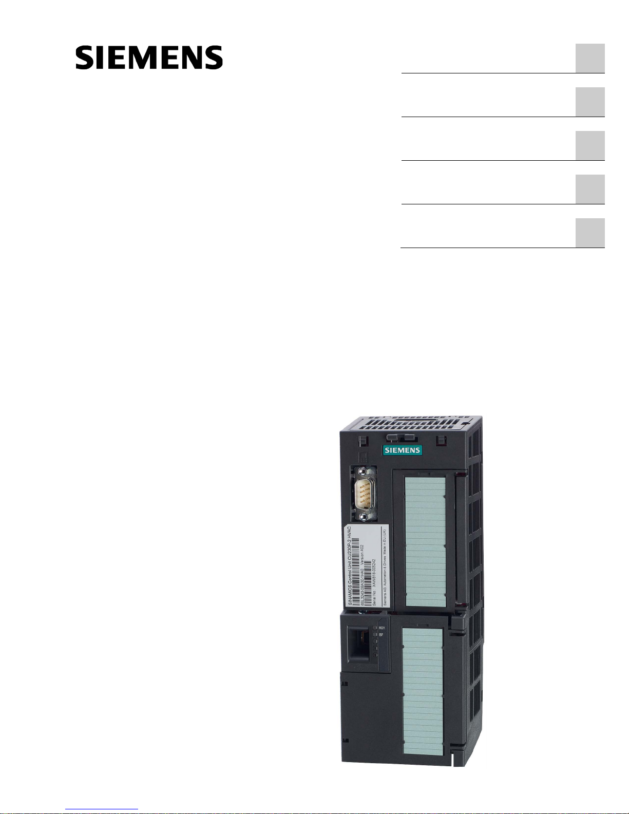
The fieldbus interface of the Control Unit depends on the Article No. You can find the
designation, the article number, the hardware version (e.g. 02) and the firmware version
(e.g. 4.6) on the Control Unit rating plate
①.
Designation
Article number
Fieldbus
CU230P-2 HVAC 6SL3243-0BB30-1HA3 USS, Modbus RTU, BACnet MS/TP,
P1
CU230P-2 DP
6SL3243-0BB30-1PA3
PROFIBUS DP
CU230P-2 PN 6SL3243-0BB30-1FA0 PROFINET IO, EtherNet/IP
● Compact Operating Instructions in German and English
● The inverter contains open-source software (OSS). OSS comprises open source text and
satisfies special license terms.
The OSS license terms are saved in the inverter. You can transfer the OSS license terms
to a PC using a memory card where you can read them.
Transferring OSS license terms to a PC
Procedure
To transfer OSS license terms to a PC, proceed as follows:
1. Switch off the inverter power supply.
2. Insert an empty memory card into the card slot of the inverter.
Overview of the interfaces (Page 10)
3. Switch on the inverter power supply.
4. The inverter writes file "Read_OSS.ZIP" to the memory card within approximately
30 seconds.
5. Switch off the inverter power supply.
6. Withdraw the memory card from the inverter.
7. Insert the memory card into the card reader of a PC.
8. Please read the license terms.
You have transferred the OSS license terms to a PC.
CU230P-2 Control Units
Compact Operating Instructions, 01/2017, A5E38815802B AA
7
3
3.1
Plugging the Control Unit onto the Power Module
Permissible Power Modules
You may operate the Control Unit with the following Power Modules:
•
PM230
•
PM240P-2
•
PM240-2
•
PM250
•
PM330
Installing the Control Unit - General
Each Power Module has an appropriate holder for the Control Unit and a release
mechanism.
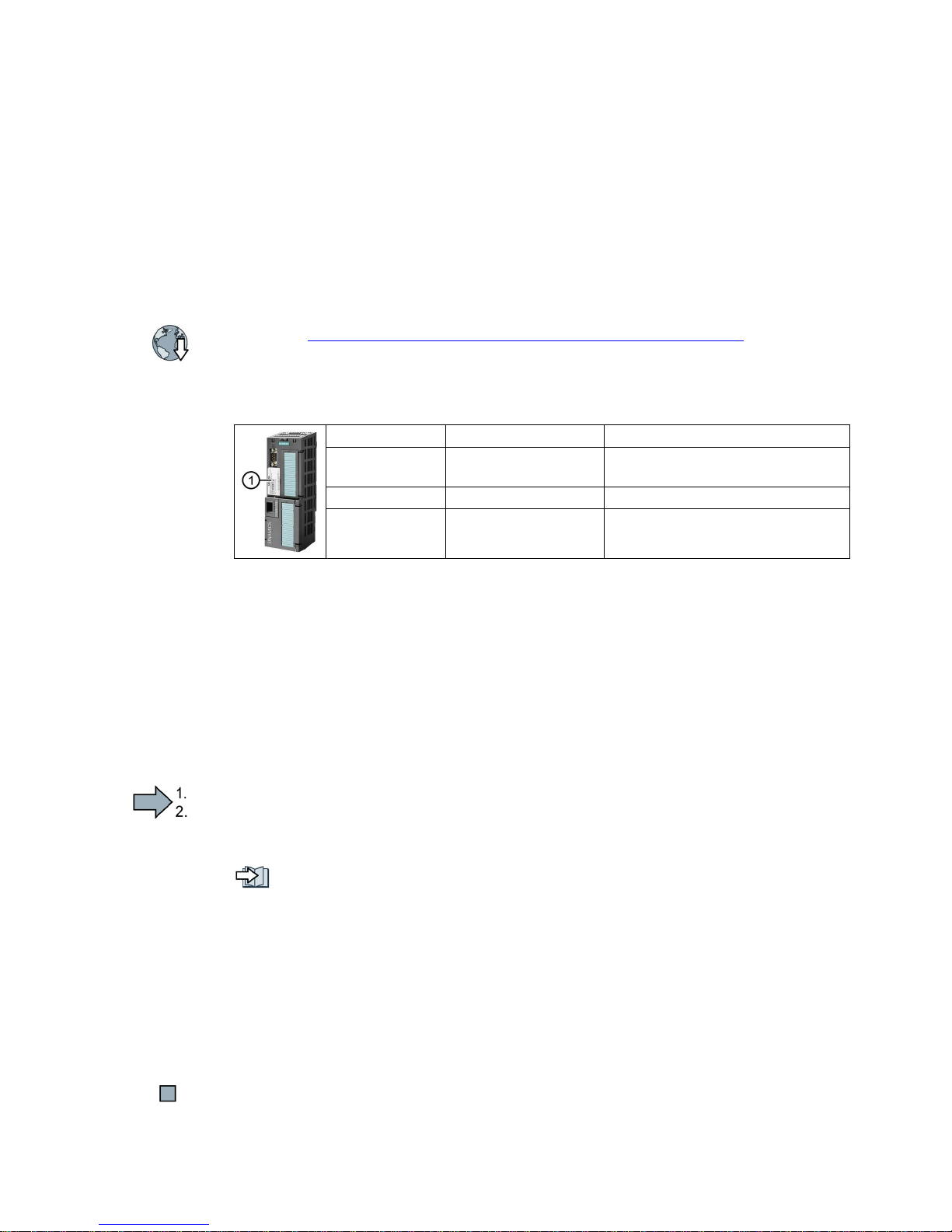
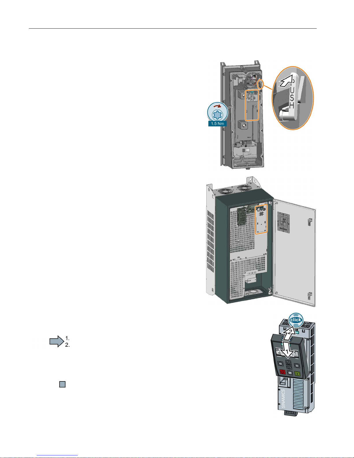
Inserting the Control Unit
Proceed as follows to plug the Control
Unit onto a Power Module:
1.
Place the two catches of the
Control Unit in the matching
grooves of the Power Module.
2.
Press the Control Unit onto the
Power Module until you hear that it
latches.
You have now plugged the Control
Unit onto the Power Module.
Removing the Control Unit
Remove the Control Unit from the Power Module by pressing the release mechanism.
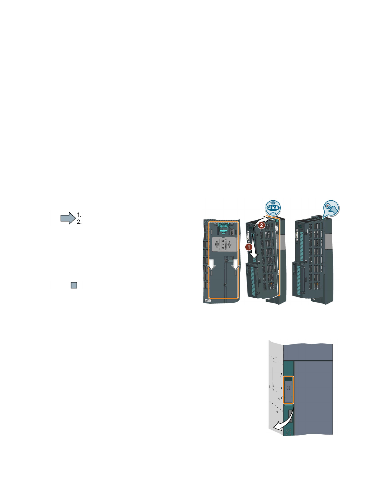
Special features for the PM330 Power Module
To insert or detach the Control Unit, you must open the left
-
hand cov
er of the Power Module.
Close the cover before you commission the inverter.
Installing
3.1 Plugging the Control Unit onto the Power Module
CU230P-2 Control Units
8 Compact Operating Instructions, 01/2017, A5E38815802B AA
Special features for the PM230 Power Module IP55, FSA … FSC
To insert or detach the
Control Unit, you must
release eight or ten fixing screws of the cover
and then remove the cover.
The Power Module release mechanism is
shown in the diagram.
Attach the cover again before you commission
the inverter. Do not damage the seal of the
cover when attaching it.
Installing the Control Unit, PM230 IP55 - FSD … FSF
To insert or detach the Control Unit, you must
open the front door of the Power Module.
Clos
e the door before you commission the in-
verter. Check to ensure that the seals are not
damaged.
Plugging on an operator panel
Procedure
To plug an Operator Panel on the Control Unit, proceed as follows:
1.
Locate the lower edge of the Operator Panel into the matching recess
of the Control Unit.
2.
Plug the Operator Panel onto the inverter until the latch audibly
engages.
You have plugged an operator panel onto the Control Unit.
The operator panel is ready for operation when you connect the inverter to the power supply.
Installing
3.1 Plugging the Control Unit onto the Power Module
CU230P-2 Control Units
Compact Operating Instructions, 01/2017, A5E38815802B AA
9
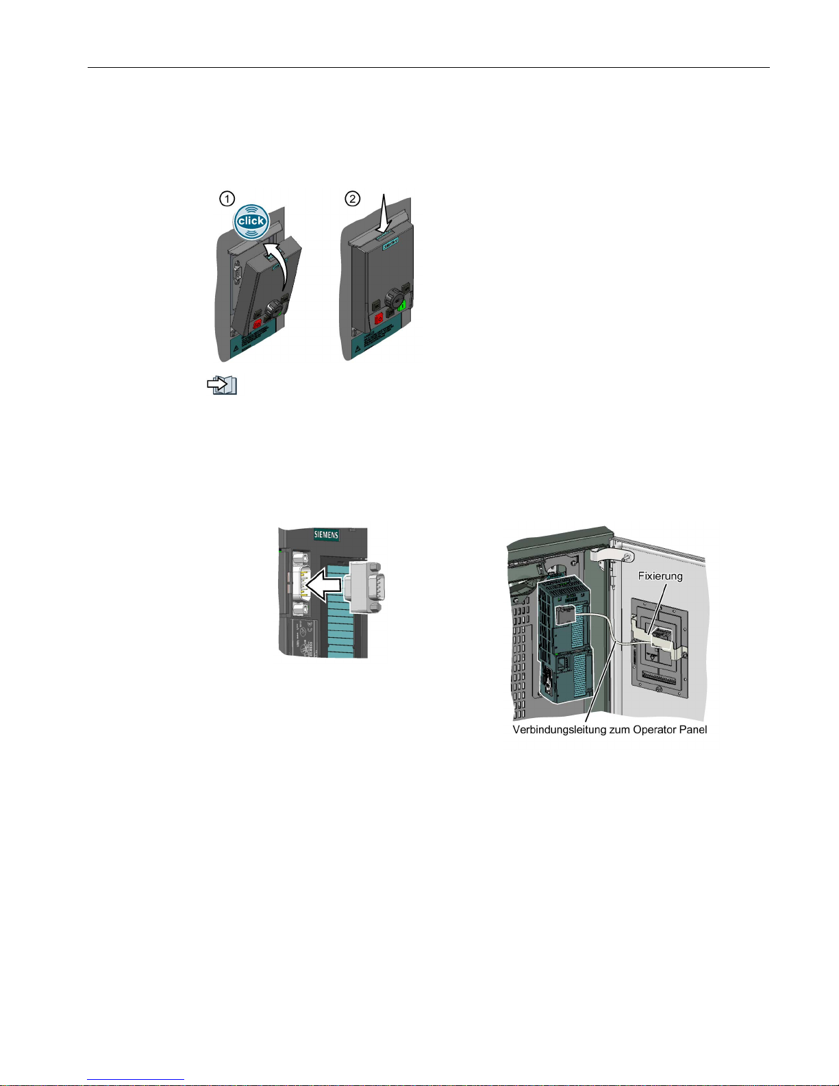
Mounting the operator panel or dummy cover on the IP55 Power Module
Either an operator panel or the dummy cover must be plugged on for the inverter to achieve
degree of protection IP55.
①
Attaching the operator panel or dummy cover:
Press the operator panel or dummy cover onto the
inverter as shown until you hear it click into place.
②
Removing the operator panel or dummy cover:
Use a suitable screwdriver to pres
s the interlock
downwards.
Tools to commission the converter (Page 33)
The following accessory is included in the Power Module scope of supply to connect the
Control Unit with the operator panel:
● An adapter, required for PM230 IP55 Power Modules, FSA … FSC
● A connecting cable and a bar to fix the connector, required for PM230 IP55 Power
Modules, FSD … FSF
Adapter
Connecting cable
Installing
3.2 Overview of the interfaces
CU230P-2 Control Units
10 Compact Operating Instructions, 01/2017, A5E38815802B AA
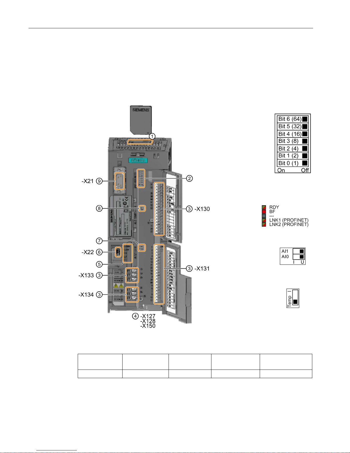
3.2
Overview of the interfaces
Interfaces at the front of the Control Unit
To access the interfaces at the front of the Control Unit, you must lift the Operator Panel (if
one is being used) and open the front doors.
①
Memory card slot
②
Selecting the
fieldbus address:
•
CU230P-2 DP
•
CU230P-2
HVAC
•
CU230P-2 BT
③
Terminal strips
④
Fieldbus interfaces at the lower
side
⑤
Status LED
⑥
USB interface for connection to a
PC
⑦
Switch for AI
0 and
AI
1 (U/I)
•
I 0/4 mA … 20 mA
•
U -10/0 V … 10 V
⑧
Switch for AI
2
Current or te
m-
per
ature input
⑨
Connection to the operator panel
Table 3- 1 Number of inputs and outputs
Digital inputs DI
Digital outputs DO
Analog inputs AI
Analog outputs AO
Input for motor tem-
perature sensor
6 3 4 2 1
Installing
3.2 Overview of the interfaces
CU230P-2 Control Units
Compact Operating Instructions, 01/2017, A5E38815802B AA
11
Table 3- 2 Permissible cables and wiring options
Solid or flexible conductors Finely stranded conductor with
non-insulated end sleeve
Finely stranded conductor with
partially insulated end sleeve
Cables with twin end sleeves are not permissible.
EMC-compliant wiring
Measures to ensure EMC-compliant wiring of the Control Unit:
● Use the shield connection kit of the Control Unit to connect the shield and provide strain
relief for cables/conductors.
Shield connection kit
Article number
Shield connection kit 1 for the CU230P-2 Control Units with all fieldbus
interfaces except for PROFINET.
6SL3264-1EA00-0FA0
Shield connection kit 3 for the CU230P-2 and CU240E-2 Control Units
with PROFINET interface.
6SL3264-1EA00-0HB0
● If you use shielded cables, then you must connect the shield to the mounting plate of the
control cabinet or with the shield support of the inverter through a good electrical
connection and a large surface area.
Additional information about EMC-compliant wiring is available on the Internet:
EMC installation guideline (http://support.automation.siemens.com/WW/view/en/60612658)
Interfaces at the lower side of the CU230P-2 Control Unit
Installing
3.3 Terminal strips
CU230P-2 Control Units
12 Compact Operating Instructions, 01/2017, A5E38815802B AA
3.3
Terminal strips
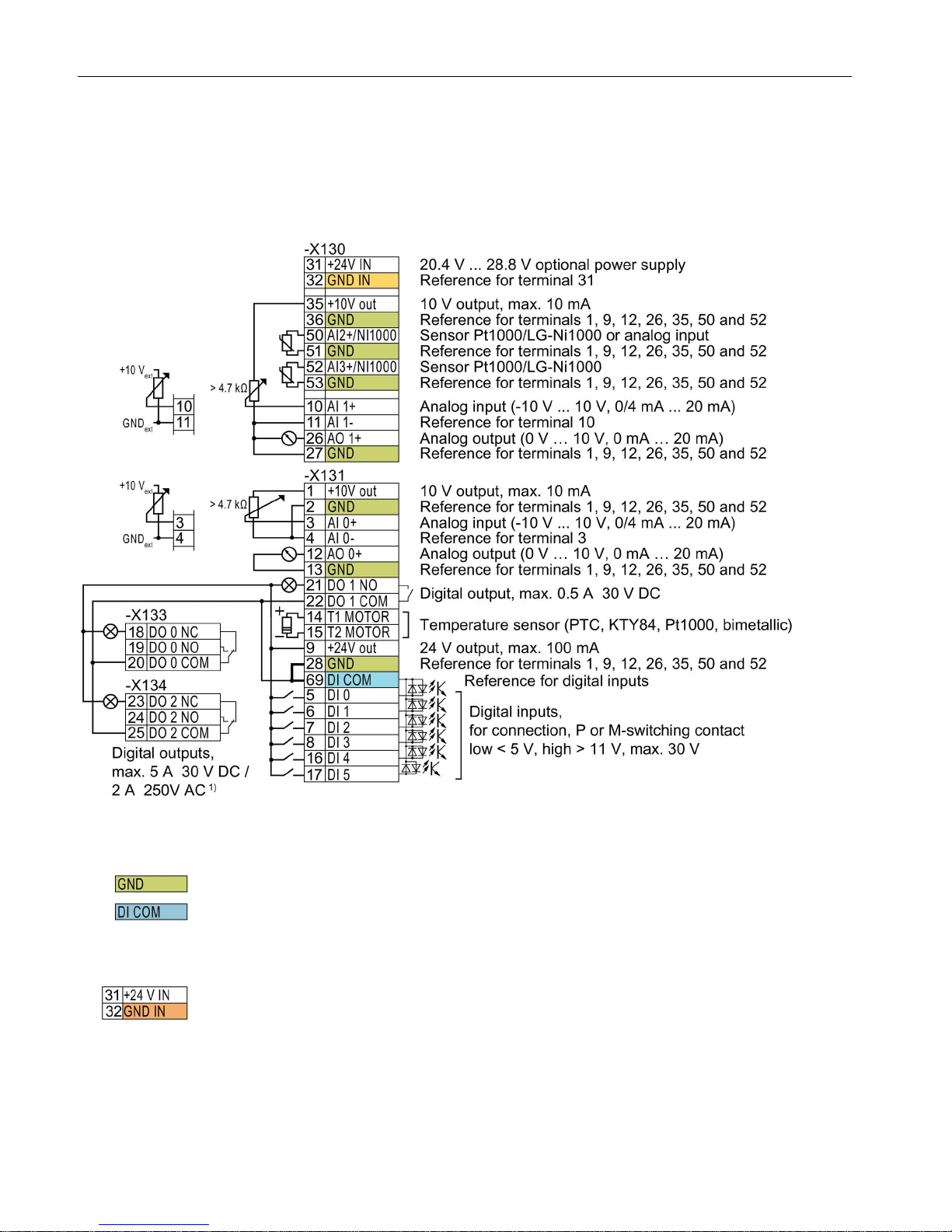
Terminal strips with wiring example
1)
The following applies to systems compliant with UL: Maximum current, 3 A 30 VDC or 2 A 250 VAC
Figure 3-1 Wiring the digital inputs with p-switching contacts and an internal 24 V power supply (terminal 9)
All terminals labelled with reference potential "GND" are connected internally in the inverter.
Reference potential "DI COM" is electrically isolated from "GND". The Control Unit is
delivered with a jumper between terminals 28 and 69.
→ If, as shown above, you wish to use the 24-V supply from terminal 9 as supply for the
digital inputs, then it is mandatory that this jumper is used.
When an optional 24 V power supply is connected at terminals 31, 32, even when the Power
Module is disconnected from the line supply, the Control Unit remains in operation. The
Control Unit thus maintains fieldbus communication, for example.
→ At terminals 31, 32, only connect a power supply that is in accordance with SELV (Safety
Extra Low Voltage) or PELV (Protective Extra Low Voltage).
Installing
3.3 Terminal strips
CU230P-2 Control Units
Compact Operating Instructions, 01/2017, A5E38815802B AA
13
→ if you also wish to use the power supply at terminals 31, 32 for the digital inputs, then you
must connect "DI COM" and "GND IN" with one another at the terminals.
You may use the internal 10 V power supply or an external power supply for the analog
inputs.
→ When you use the internal 10 V power supply, you must connect AI 0 or AI 1 with "GND".
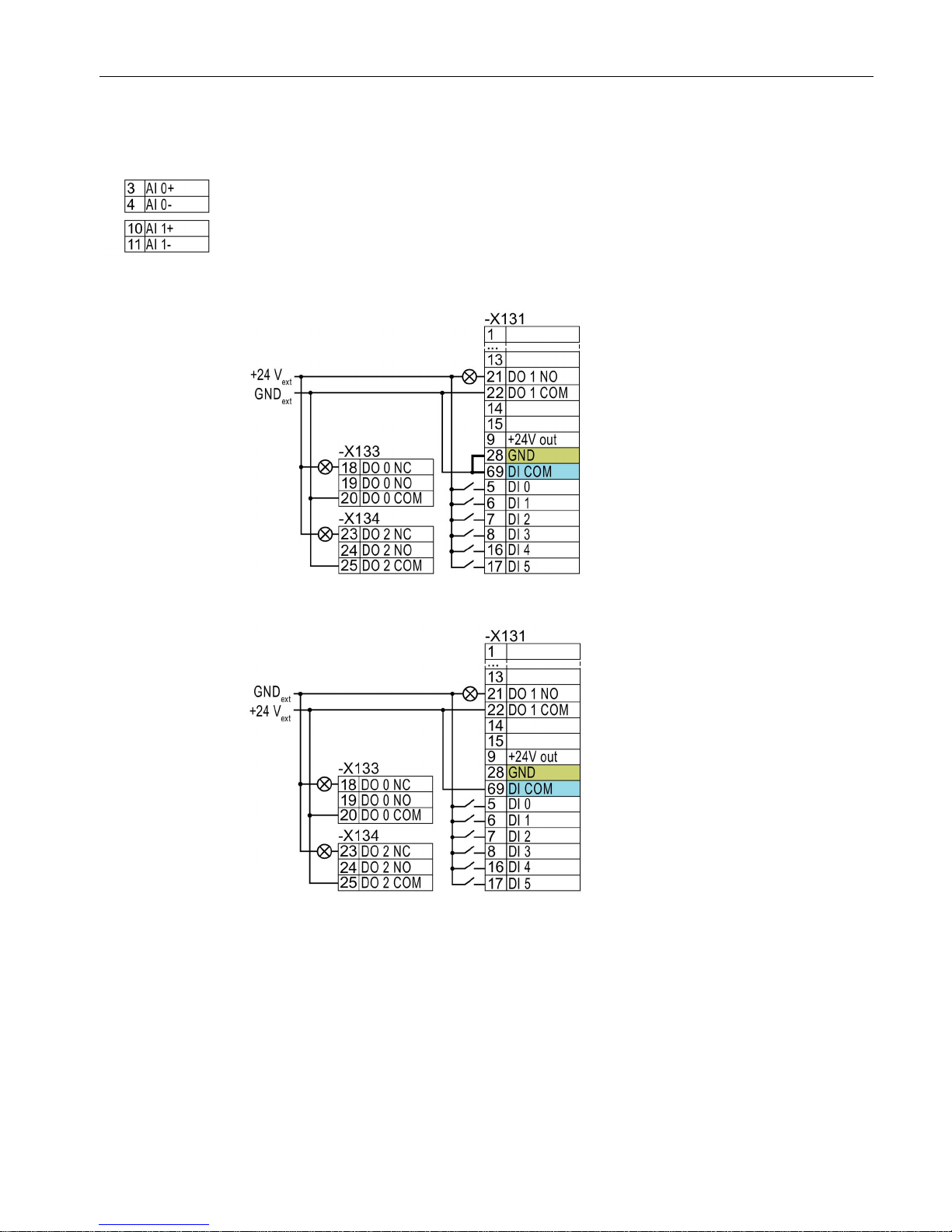
Additional options for wiring the digital inputs
Connecting P-switching contacts with an external
power supply
You must remove the jumper between
terminals 28 and 69 if it is necessary to
have electrical isolation between the
external power supply and the internal
inverter power supply.
Connecting M-switching contacts with an external
power supply
Remove the jumper between terminals
28 and 69.
Installing
3.4 Factory interface settings
CU230P-2 Control Units
14 Compact Operating Instructions, 01/2017, A5E38815802B AA
3.4
Factory interface settings
The factory setting of the interfaces depends on the Control Unit.
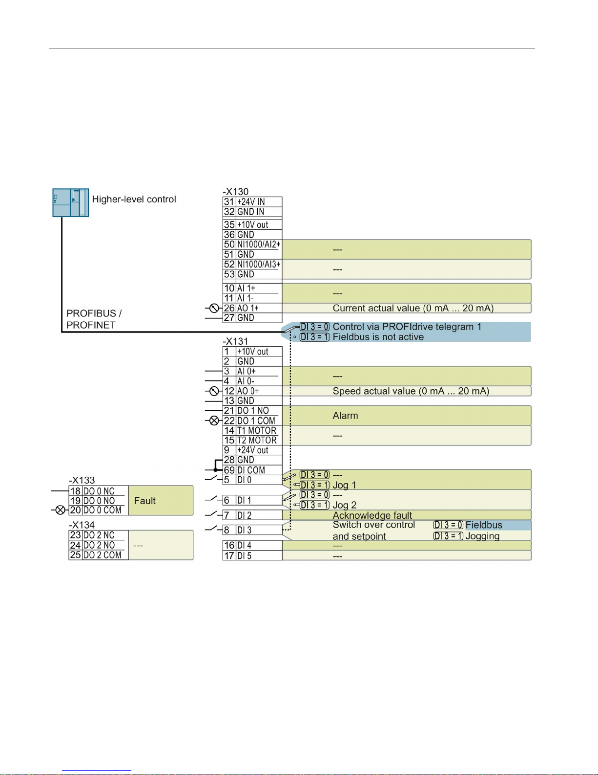
Control Units with PROFIBUS or PROFINET interface
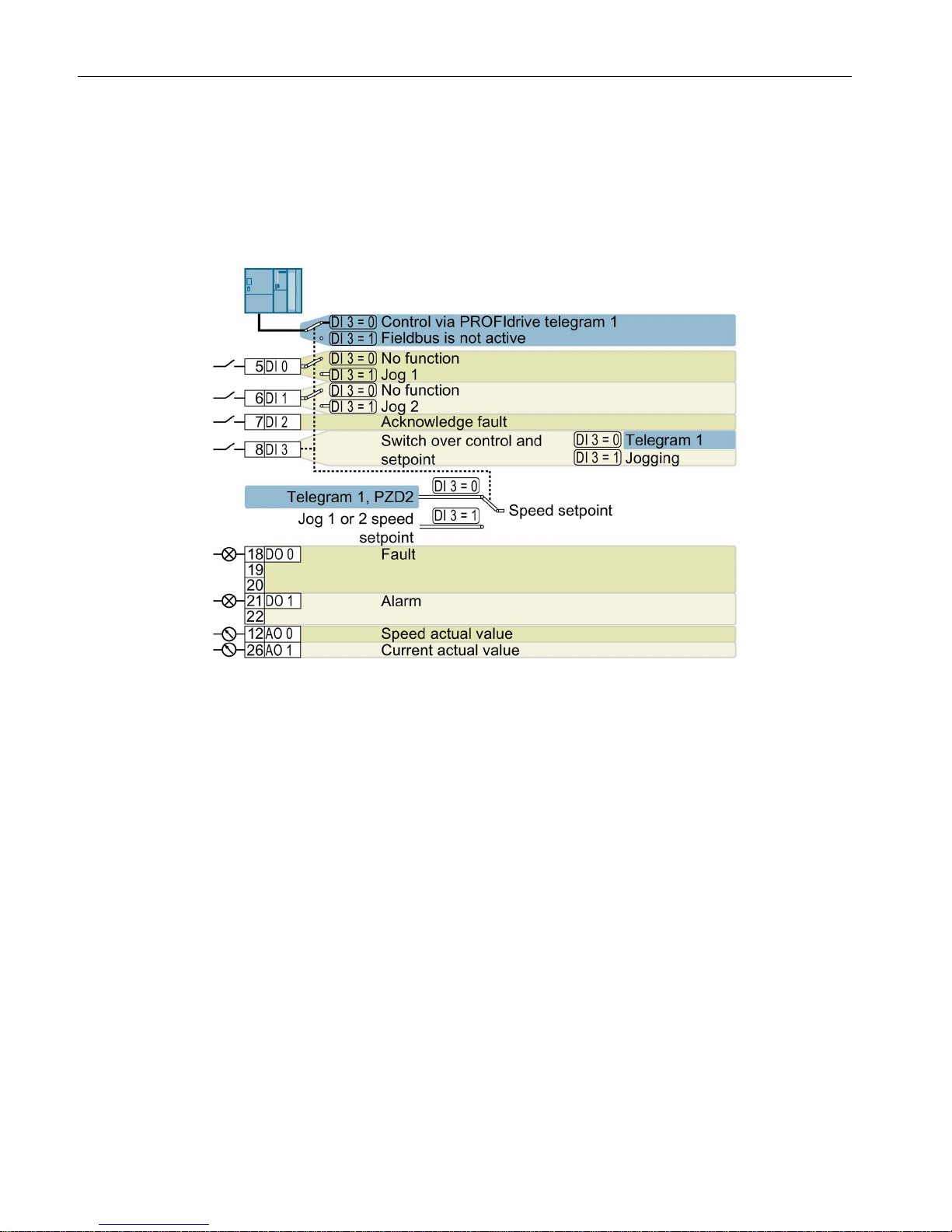
The function of the fieldbus interface and digital inputs DI 0, DI 1 depends on DI 3.
--- No function.
DO x: p073x
AO 0: p0771[0]
DI x: r0722.x
Speed setpoint (main setpoint): p1070[0] = 2050[1]
Figure 3-2 Factory setting of the CU230P-2 DP and CU230P-2 PN Control Units
Installing
3.4 Factory interface settings
CU230P-2 Control Units
Compact Operating Instructions, 01/2017, A5E38815802B AA
15
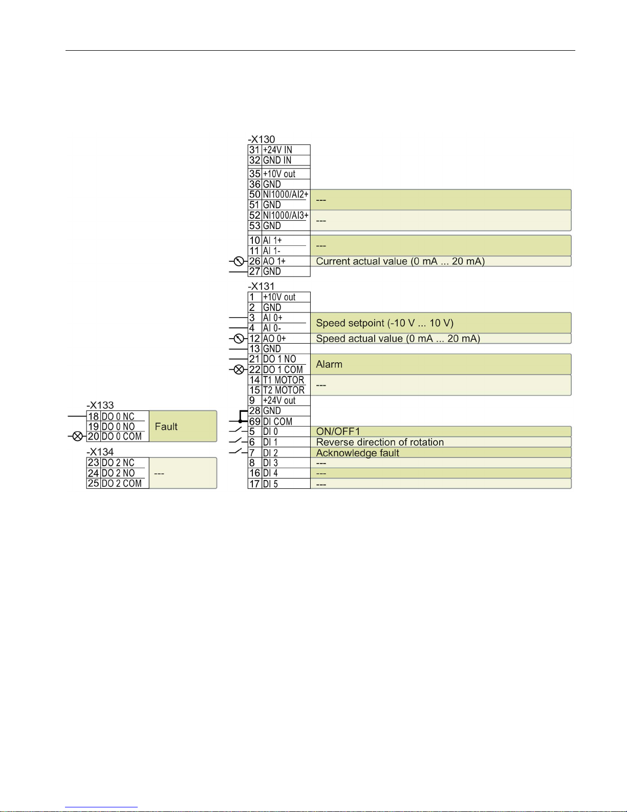
Control Units with USS interface
The fieldbus interface is not active.
--- No function.
DO x: p073x
AO 0: p0771[0]
DI x: r0722.x
AI 0: r0755[0]
Speed setpoint (main setpoint): p1070[0] = 755[0]
Figure 3-3 Factory setting of CU230P-2 HVAC Control Units
Changing the function of the terminals
The function of the terminals and fieldbus interface can be adjusted.
In order that you do not have to successively change terminal for terminal, several terminals
can be jointly set using default settings ("p0015 Macro drive unit").
The terminal settings made in the factory described above correspond to the following
default settings:
● Default setting 12 (p0015 = 12): "Standard I/O with analog setpoint"
● Default setting 7 (p0015 = 7): "Fieldbus with data set switchover"
Installing
3.5 Default setting of the interfaces
CU230P-2 Control Units
16 Compact Operating Instructions, 01/2017, A5E38815802B AA
3.5
Default setting of the interfaces
Default setting 7: "Fieldbus with data set switchover"
Factory setting for inverters with PROFIBUS or PROFINET interface
DO 0: p0730, DO 1: p0731
AO 0: p0771[0], AO 1: p0771[1]
DI 0: r0722.0, …, DI 3: r0722.3
Speed setpoint (main setpoint): p1070[0] = 2050[1]
Jog 1 speed setpoint: p1058, factory setting: 150 rpm
Jog 2 speed setpoint: p1059, factory setting: -150 rpm
Designation in the BOP-2: FB cdS
 Loading...