

Siemens SINAMICS G120P Hardware Installation Manual


PM230 Power Module IP55
___________________
___________________
___________________
___________________
___________________
___________________
___________________
SINAMICS
SINAMICS G120P
PM230 Power Module IP55
Hardware Installation Manual
11/2014
A5E35319202B AA
Introduction
1
Safety notes
2
Installing / mounting
3
Connecting
4
Service and maintenance
5
Technical specifications
6
Appendix
7

Siemens AG
Division Digital Factory
Postfach 48 48
90026 NÜRNBERG
GERMANY
A5E35319202B AA
Ⓟ
Copyright © Siemens AG 2010 - 2014.
All rights reserved
Legal information
Warning notice system
DANGER
indicates that death or severe personal injury will result if proper precautions are not taken.
WARNING
indicates that death or severe personal injury may result if proper precautions are not taken.
CAUTION
indicates that minor personal injury can result if proper precautions are not taken.
NOTICE
indicates that property damage can result if proper precautions are not taken.
Qualified Personnel
personnel qualified
Proper use of Siemens products
WARNING
Siemens products may only be used for the applications described in the catalog and in the relevant technical
maintenance are required to ensure that the products operate safely and without any problems. The permissible
ambient conditions must be complied with. The information in the relevant documentation must be observed.
Trademarks
Disclaimer of Liability
This manual contains notices you have to observe in order to ensure your personal safety, as well as to prevent
damage to property. The notices referring to your personal safety are highlighted in the manual by a safety alert
symbol, notices referring only to property damage have no safety alert symbol. These notices shown below are
graded according to the degree of danger.
If more than one degree of danger is present, the warning notice representing the highest degree of danger will
be used. A notice warning of injury to persons with a safety alert symbol may also include a warning relating to
property damage.
The product/system described in this documentation may be operated only by
task in accordance with the relevant documentation, in particular its warning notices and safety instructions.
Qualified personnel are those who, based on their training and experience, are capable of identifying risks and
avoiding potential hazards when working with these products/systems.
Note the following:
documentation. If products and components from other manufacturers are used, these must be recommended
or approved by Siemens. Proper transport, storage, installation, assembly, commissioning, operation and
All names identified by ® are registered trademarks of Siemens AG. The remaining trademarks in this publication
may be trademarks whose use by third parties for their own purposes could violate the rights of the owner.
We have reviewed the contents of this publication to ensure consistency with the hardware and software
described. Since variance cannot be precluded entirely, we cannot guarantee full consistency. However, the
information in this publication is reviewed regularly and any necessary corrections are included in subsequent
editions.
for the specific
11/2014 Subject to change

Table of contents
1 Introduction ............................................................................................................................................. 7
2 Safety notes .......................................................................................................................................... 13
3 Installing / mounting .............................................................................................................................. 19
4 Connecting ........................................................................................................................................... 37
5 Service and maintenance ...................................................................................................................... 61
6 Technical specifications ........................................................................................................................ 73
1.1 System overview of the SINAMICS G120P .............................................................................. 7
1.2 Documents for the Inverter ..................................................................................................... 12
3.1 Air cooling requirements ......................................................................................................... 21
3.2 Dimensions and drill patterns ................................................................................................. 22
3.3 Control Unit installation ........................................................................................................... 29
3.4 Fitting the IOP and the blanking plate..................................................................................... 34
4.1 Power distribution systems ..................................................................................................... 38
4.2 Operation only with grounded (TN) supplies .......................................................................... 38
4.3 Motor cable lengths and cross-sections ................................................................................. 39
4.4 Access to power and motor terminals ..................................................................................... 43
4.5 Cable preparation ................................................................................................................... 46
4.6 Wiring Sequence ..................................................................................................................... 47
4.7 Power and motor connections ................................................................................................ 50
4.8 Gland plate installation............................................................................................................ 51
4.9 EMC guidelines ....................................................................................................................... 54
4.9.1 Avoiding electromagnetic interference .................................................................................... 54
4.9.2 Connections and interference suppression ............................................................................ 54
4.9.3 Cabling .................................................................................................................................... 54
4.9.4 Equipotential bonding ............................................................................................................. 55
4.9.5 Inverter shielding in detail, FSA to FSC .................................................................................. 58
5.1 Maintenance ........................................................................................................................... 61
5.1.1 Maintenance ........................................................................................................................... 61
5.1.2 Cleaning .................................................................................................................................. 61
5.2 Replacing components ........................................................................................................... 62
5.2.1 Replacing the cooling fan ....................................................................................................... 62
5.2.1.1 Replacement fans ................................................................................................................... 69
5.3 Spares and accessories.......................................................................................................... 71
6.1 General data, PM230, IP55 .................................................................................................... 74
PM230 Power Module IP55
Hardware Installation Manual, 11/2014, A5E35319202B AA
5

Table of contents
7 Appendix .............................................................................................................................................. 83
Index .................................................................................................................................................... 91
6.2 Temperature, altitude and voltage derating PM230............................................................... 75
6.3 Technical data ........................................................................................................................ 77
6.3.1 Input current operation ........................................................................................................... 77
6.4 Current reduction depending on pulse frequency .................................................................. 82
7.1 Electromagnetic Compatibility ................................................................................................ 83
7.2 Definition of the EMC Environment and Categories .............................................................. 84
7.3 EMC overall performance ...................................................................................................... 86
7.4 Standards ............................................................................................................................... 88
7.5 Abbreviations ......................................................................................................................... 89
PM230 Power Module IP55
6 Hardware Installation Manual, 11/2014, A5E35319202B AA

1
1.1
System overview of the SINAMICS G120P
The SINAMICS G120 range
Available Power Modules PM230
PM230 Power Modules with integrated filter Class A
PM230 Power Modules with integrated filter Class B
Control Unit - CU230P-2
•
with RS485 interface for USS, Modbus RTU and BacNet MS/TP
•
with CANopen interface
•
with PROFIBUS DP interface
The SINAMICS G120 inverter has been designed for the accurate and efficient control of the
speed and torque for three-phase motors. The SINAMICS G120P is a specific sub-system
focused on the HVAC industry sector and for pump and fan applications. .
The PM230 Power Modules supply the necessary power to the Control Units and the
attached motor. The PM230 output ranges from 0.37 kW to 90 kW and is rated IP55 (UL
Type 12).
See the respective manual for specific functions and features.
The various types of PM230 Power Modules are listed below. The given power rating values
are defined for "low overload" operation.
●
3 AC, 380 V … 480 V ± 10%, IP55 (UL Type 12), Frame size A … F, 0,37 kW … 90.0 kW
●
3 AC, 380 V … 480 V ± 10%, IP55 (UL Type 12), Frame size A … F, 0,37 kW … 90.0 kW
The CU230P-2 is a Control Unit that has been optimized for pumps and fans. It can be
operated with the PM230 Power Module.
CU230P-2 HVAC
CU230P-2 CAN
CU230P-2 DP
The Control Unit can be commissioned either using the STARTER commissioing software or
the optional Intelligent Operator Panel (IOP).
You can save all the settings you enter during commissioning and operation to a memory
card.
PM230 Power Module IP55
Hardware Installation Manual, 11/2014, A5E35319202B AA
7

Introduction
Intelligent Operator Panel
Rating label information
1.1 System overview of the SINAMICS G120P
The Intelligent Operator Panel (IOP) has been designed to enhance the interface and
communications capabilities of the SINAMICS G120P Inverters.
Every Power Module has a rating label which details the specifications of the Power Module.
The specifications shown on the rating label can vary due to the requirements of specific
regulations and compliance standards imposed by the country of origin and the final
destination of the product.
Detailed below is an explanation of all the information that might appear on a typical rating
label of a Power Module.
Figure 1-1 Typical Power Module rating labels
PM230 Power Module IP55
8 Hardware Installation Manual, 11/2014, A5E35319202B AA

Introduction
Item
Description
Notes
3
Rated input current
4 Nominal input frequency
range.
6
Nominal current
7 European motor rating
8
North America motor rating
against environmental conditions.
10
Weight
It is the weight of the product only.
11
Temperature range
Is the operating temperature range of the the product.
12
The country of origin and manufacture
Hardware Installation Manual for the product.
Hardware Installation Manual for the product.
15
Order number
16
Hardware version
17
Serial number
1.1 System overview of the SINAMICS G120P
Table 1- 1 Explanation of Power Module rating label information
1 Product name
2 Input voltage range
5 Output voltage range This is determined by the range of the input voltage
9 Protection rating The IP rating denotes the protection the product has
13 European Low Voltage Directive Compliance Full details are contained the Operating Instructions or
14 Underwriters Laboratories listed equipment standard Full details are contained the Operating Instructions or
PM230 Power Module IP55
Hardware Installation Manual, 11/2014, A5E35319202B AA
9

Introduction
Order Number
1.1 System overview of the SINAMICS G120P
Each type of Power Module has a unique order number, also known as the MLFB
(Maschinenlesbare Fabrikatebezeichnung). The order number contains detailed information
regarding the type and specification of the product. In the figure below details of how the
order number is constructed are given.
Figure 1-2 Breakdown of Order Number (MLFB)
PM230 Power Module IP55
10 Hardware Installation Manual, 11/2014, A5E35319202B AA
Introduction
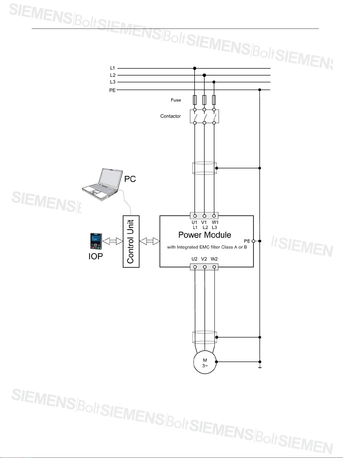
Block diagram PM230 FSA ... FSF
1.1 System overview of the SINAMICS G120P
Figure 1-3 Block diagram PM230
PM230 Power Module IP55
Hardware Installation Manual, 11/2014, A5E35319202B AA
11

Introduction
1.2
Documents for the Inverter
Available technical documentation
Documents for the Control Unit CU230P-2
Further internet addresses
1.2 Documents for the Inverter
Comprehensive information and support tools are available from the Service and Support
internet site at the following link:
● http://support.automation.siemens.com
Examples of the types of documentation and support tools available for downloading are:
● Getting Started Guides
● Operating Instructions
● Hardware Installation Manuals
● Parameter Manuals
● STARTER commissioning software
Since the CU230P-2 Control Unit has been designed to support the HVAC environment; the
following documents for the CU230P-2 can be found at the links below:
● Getting Started Guide
http://support.automation.siemens.com/WW/view/en/36175006
● Operating Instructions
http://support.automation.siemens.com/WW/view/en/36175032
● Parameter Manual
http://support.automation.siemens.com/WW/view/en/36147790
You find various application examples to the inverters under the following link:
● http://support.automation.siemens.com/WW/view/en/20208582/136000
PM230 Power Module IP55
12 Hardware Installation Manual, 11/2014, A5E35319202B AA

2
Safety Instructions
The following Warnings, Cautions and Notes are provided for your safety and as a means of
preventing damage to the product or components in the connected machines. This section
lists Warnings, Cautions and Notes, which apply generally when handling the inverter,
classified as General, Transport and Storage, Commissioning, Operation, Repair and
Dismantling and Disposal.
Specific Warnings, Cautions and Notes that apply to particular activities are listed at the
beginning of the relevant sections in this manual and are repeated or supplemented at
critical points throughout these sections.
Please read the information carefully, since it is provided for your personal safety and will
also help prolong the service life of your inverter and the equipment to which it is connected.
It has to be ensured by the machine manufacturer, that the line-side overcurrent protection
equipment interrupts within 5 s (immovable equipment and modules in immovable
equipment) in the case of minimum fault current (current on complete insulation failure to
accessible conductive parts that are not live during operation and maximum current loop
resistance).
The machine manufacturer must ensure that the voltage drop between the main power
supply and the power drive system, during operation, does not exceed 1 % (UK < 1 %).
PM230 Power Module IP55
Hardware Installation Manual, 11/2014, A5E35319202B AA
13
Safety notes
General
WARNING
This equipment contains dangerous voltages and controls potentially dangerous rotating
mechanical parts. Non-compliance with the warnings or failure to follow the instructions
contained in this manual can result in loss of life, severe personal injury or serious damage
to property.
Protection in case of direct contact by means of SELV / PELV is only permissible in areas
with equipotential bonding and in dry indoor rooms. If these conditions are not fulfilled,
other protective measures against electric shock must be applied e.g. protective insulation.
Only suitably qualified personnel should work on this equipment, and only after becoming
familiar with all safety notices, installation, operation and maintenance procedures
contained in this manual. The successful and safe operation of this equipment is dependent
upon its proper handling, installation, operation and maintenance.
As the earth leakage for this product can be greater than 3.5 mA a.c., a fixed earth
connection is required and the minimum size of the protective earth conductor shall comply
with the local safety regulations for high leakage current equipment. In this case a
permanent, immovable connection is required and the following measures must also be
taken:
2
• Minimum PE conductor cross-section of 10 mm
• Laying a second PE conductor using separate terminals, with a cross-section that, in
itself, fulfills all the requirements for PE conductors.
• Self-actuating switch-off of the power supply if the PE conductor is interrupted.
• Insertion of a two-winding transformer into the power supply.
.
Due to the high inrush currents in the earth conductor, this product is not compatible with
an RCD (also referred to as an ELCB or RCCB).
The power supply, DC and motor terminals, the brake and thermistor cables can carry
dangerous voltages even if the inverter is inoperative. Wait at least five minutes to allow the
unit to discharge after switching off the line supply before carrying out any installation work.
It is strictly prohibited for any mains disconnection to be performed on the motor-side of the
system; any disconnection of the mains must be performed on the mains-side of the
Inverter.
When connecting the line supply to the Inverter, make sure that the terminal case of the
motor is closed.
During operation and for a short time after switching-off the Inverter, the surfaces of the
Inverter can reach a high temperature.
This equipment is capable of providing internal motor overload protection according to
UL508C. Refer to P0610 and P0335, i²t is ON by default.
When changing from the ON to OFF-state of an operation if an LED or other similar display
is not lit or active; this does not indicate that the unit is switched-off or powered-down.
The inverter must always be grounded.
Isolate the line supply before making or changing connections to the unit.
PM230 Power Module IP55
14 Hardware Installation Manual, 11/2014, A5E35319202B AA
Safety notes
Use of mobile radio devices (e.g. telephones, walkie-talkies) with a transmission power > 1
CAUTION
Note
Keep this manual within easy reach of the equipment and make it available to all users.
Whenever measuring or testing has to be performed on live equipment, the regulations of
Safety Code BGV A2 must be observed, in particular §
Working on Live Parts". Suitable electronic tools should be used.
Before installing and commissioning, please read these safety instructions and warnings
carefully and all
labels are kept in a legible condition and replace missing or damaged labels.
W in the immediate vicinity of the devices (< 1.8 m) can interfere with the functioning of the
equipment.
Do not disconnect power connections when the Inverter and motor are under load.
Ensure that the inverter is configured for the correct supply voltage. The inverter must not
be connected to a higher voltage supply.
Static discharges on surfaces or interfaces that are not generally accessible (e.g. terminal
or connector pins) can cause malfunctions or defects. Therefore, when working with
inverters or inverter components, ESD protective measures should be observed.
Take particular notice of the general and regional installation and safety regulations
regarding work on dangerous voltage installations (e.g. EN 50178) as well as the relevant
regulations regarding the correct use of tools and personal protective equipment (PPE).
Children and the general public must be prevented from accessing or approaching the
equipment!
This equipment may only be used for the purpose specified by the manufacturer.
Unauthorized modifications and the use of spare parts and accessories that are not sold or
recommended by the manufacturer of the equipment can cause fires, electric shocks and
injuries.
8 "Permissible Deviations when
the warning labels attached to the equipment. Make sure that the warning
PM230 Power Module IP55
Hardware Installation Manual, 11/2014, A5E35319202B AA
15
Safety notes
Transport and storage
WARNING
CAUTION
Commissioning
WARNING
CAUTION
Cable connection
Correct transport, storage as well as careful operation and maintenance are essential for
the proper and safe operation of the equipment.
Protect the equipment against physical shocks and vibration during transport and storage. It
is important that the equipment is protected from water (rainfall) and excessive
temperatures.
Working on the equipment by unqualified personnel or failure to comply with warnings can
result in severe personal injury or serious damage to material. Only suitably qualified
personnel trained in the setup, installation, commissioning and operation of the product
should carry out work on the equipment.
The control cables must be laid separately from the power cables. Carry out the
connections as shown in the installation section in this manual, to prevent inductive and
capacitive interference from affecting the correct function of the system.
PM230 Power Module IP55
16 Hardware Installation Manual, 11/2014, A5E35319202B AA
Safety notes
Operation
WARNING
Repair
WARNING
Dismantling and disposal
NOTICE
The Inverter operate at high voltages.
When operating electrical devices, it is impossible to avoid applying hazardous voltages to
certain parts of the equipment.
Emergency Stop facilities according to EN 60204, IEC 204 (VDE 0113) must remain
operative in all operating modes of the control equipment. Any disengagement of the
Emergency Stop facility must not lead to an uncontrolled or an undefined restart of the
equipment.
Certain parameter settings may cause the Inverter to restart automatically after an input
power failure, for example, the automatic restart function.
Wherever faults occurring in the control equipment can lead to substantial material damage
or even grievous bodily injury (that is, potentially dangerous faults), additional external
precautions must be taken or facilities provided to ensure or enforce safe operation, even
when a fault occurs (e.g. independent limit switches, mechanical interlocks, etc.).
Motor parameters must be accurately configured for motor overload protection to operate
correctly.
This equipment is capable of providing internal motor overload protection according to
UL508C.
Only Inverters with fail-safe functions can be used as an "Emergency Stop Mechanism"
(see EN 60204, section 9.2.5.4).
Repairs on equipment may only be carried out by Siemens Service, by repair centers
authorized by Siemens or by authorized personnel who are thoroughly acquainted with all
the warnings and operating procedures contained in this manual.
Any defective parts or components must be replaced using parts contained in the relevant
spare parts list.
Disconnect the power supply before opening the equipment for access.
The packaging of the Inverter is re-usable. Retain the packaging for future use.
Easy-to-release screw and snap connectors allow you to break the unit down into its
component parts. You can recycle these component parts, dispose of them in accordance
with local requirements or return them to the manufacturer.
PM230 Power Module IP55
Hardware Installation Manual, 11/2014, A5E35319202B AA
17

Safety notes
PM230 Power Module IP55
18 Hardware Installation Manual, 11/2014, A5E35319202B AA
3
WARNING
General rules for protecting Power Modules against environmental effects
•
•
•
•
•
•
•
•
To ensure the safe operation of the equipment, it must be installed and commissioned by
qualified personnel in full compliance with the warnings laid down in this manual.
Take particular note of the general and regional installation and safety regulations
regarding work on dangerous voltage installation (e.g. EN 61800-5-1) as well as the
relevant regulations regarding the correct use of tools and personal protective equipment
(PPE).
To ensure that the Power Module is installed in the correct environmental conditions, please
ensure that you adhere to the following guidelines:
Power Modules FSA … FSF are designed for degree of protection IP55. There is limited
protection against the ingress of dust (no damaging deposits) and against splashing
water from all directions (slight ingress of water is permissible).
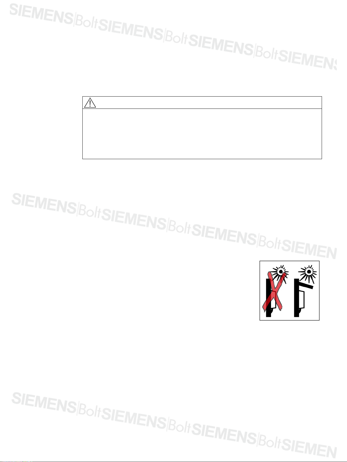
Although the Power Module is protected against the ingress of water, this protection is
dependent however on all the seals being correctly installed (e.g. seals when mounting
an operator panel).
Direct solar radiation is not permissible
Keep the Power Modules free of dust and dirt.
Keep the Power Modules away from solvents and chemicals.
The temperature of the Power Module must lie within the
operating temperature range.
Ensure that the correct level of ventilation and air flow is
provided.
Ensure that all Power Modules are grounded according to the
guidelines provided in this document.
PM230 Power Module IP55
Hardware Installation Manual, 11/2014, A5E35319202B AA
19
Installing / mounting
WARNING
Heat sink fixing screws
CAUTION
Mounting and cooling the Power Module
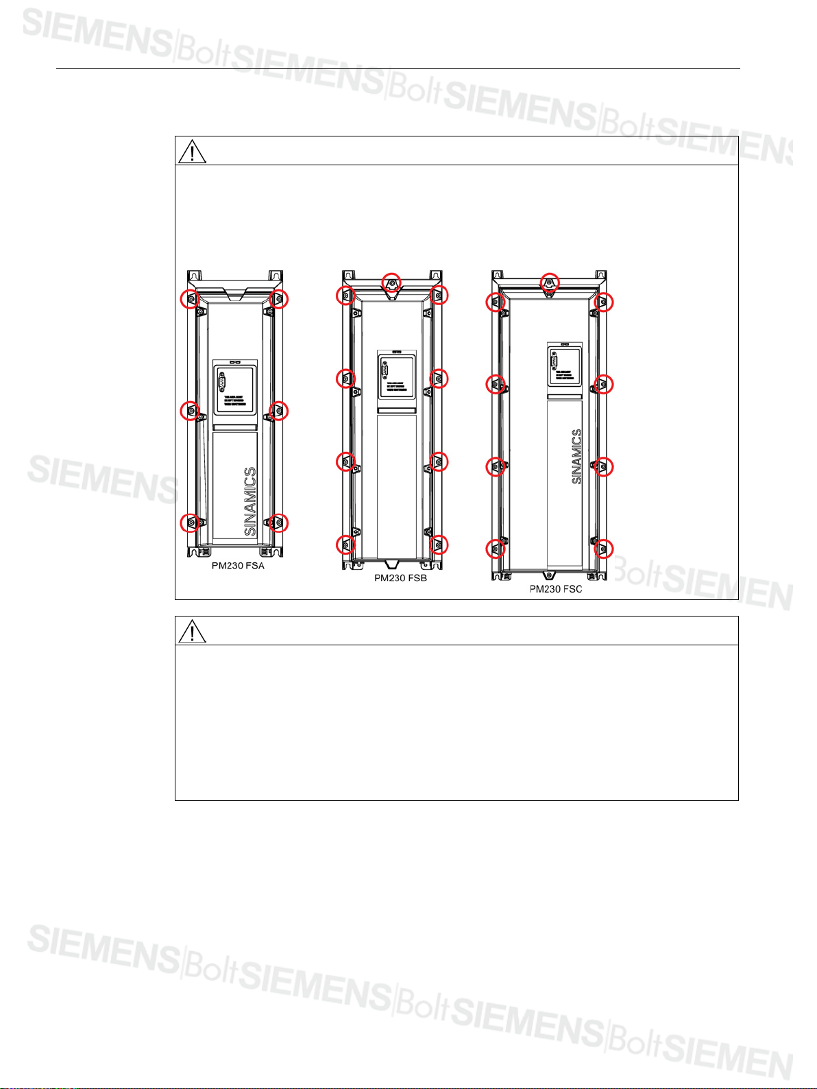
The heatsinks of the PM230 IP55 (FSA to FSC) Power Modules have several screws to fix
them to the main housing of the Power Module. It is NOT permissible that these screws are
removed. The fixing screws of the heat sink are shown in the adjacent diagram (with red
circles).
The Power Module should be mounted on a wall or panel. This ensures that the rear
module panel is located on a flat surface, and the correct airflow is achieved to optimally
cool the Power Module. If the Power Module is not mounted onto a wall panel, then the rear
panel of the heat sink must be covered with a flat surface. This then ensures that the
correct airflow is achieved.
It must be ensured that the internal fan of the Power Module is correctly mounted before
the inverter is commissioned. If this is not observed, then the inverter can overheat.
PM230 Power Module IP55
20 Hardware Installation Manual, 11/2014, A5E35319202B AA

Installing / mounting
3.1
Air cooling requirements
Air cooling requirements
Required cooling air flow
I/s
CFM
FSA
0.37 kW ... 3.0 kW
7
14
FSB
4.0 kW ... 7.5 kW
9
19
FSC
11.0 kW ... 18.5 kW
20
40
FSD
22.0 kW ... 30.0 kW
55
120
FSF
55.0 kW ... 90 kW
150
320
For Power Module
Power losses of …
FSA
FSB
FSC
FSD
FSE
FSF
150
300
500
1300
2500
Control Unit
<40
3.1 Air cooling requirements
Table 3- 1 Air cooling requirements for operation with rated power (LO)
Frame
size
FSE 37.0 kW ... 45.0 kW 110 240
Table 3- 2 Power losses of Power Module components in Watts (@ nominal voltage)
Power Module 20 …
LO power rating
25 …
30 …
440 ... 720 1000 ...
Further information is given in the technical specifications.
1500 ...
PM230 Power Module IP55
Hardware Installation Manual, 11/2014, A5E35319202B AA
21

Installing / mounting
3.2
Dimensions and drill patterns
Dimensions, drill patterns and minimum distances
Minimum distances FSA
Note
side
0 inches
3.93 inches
3.93 inches
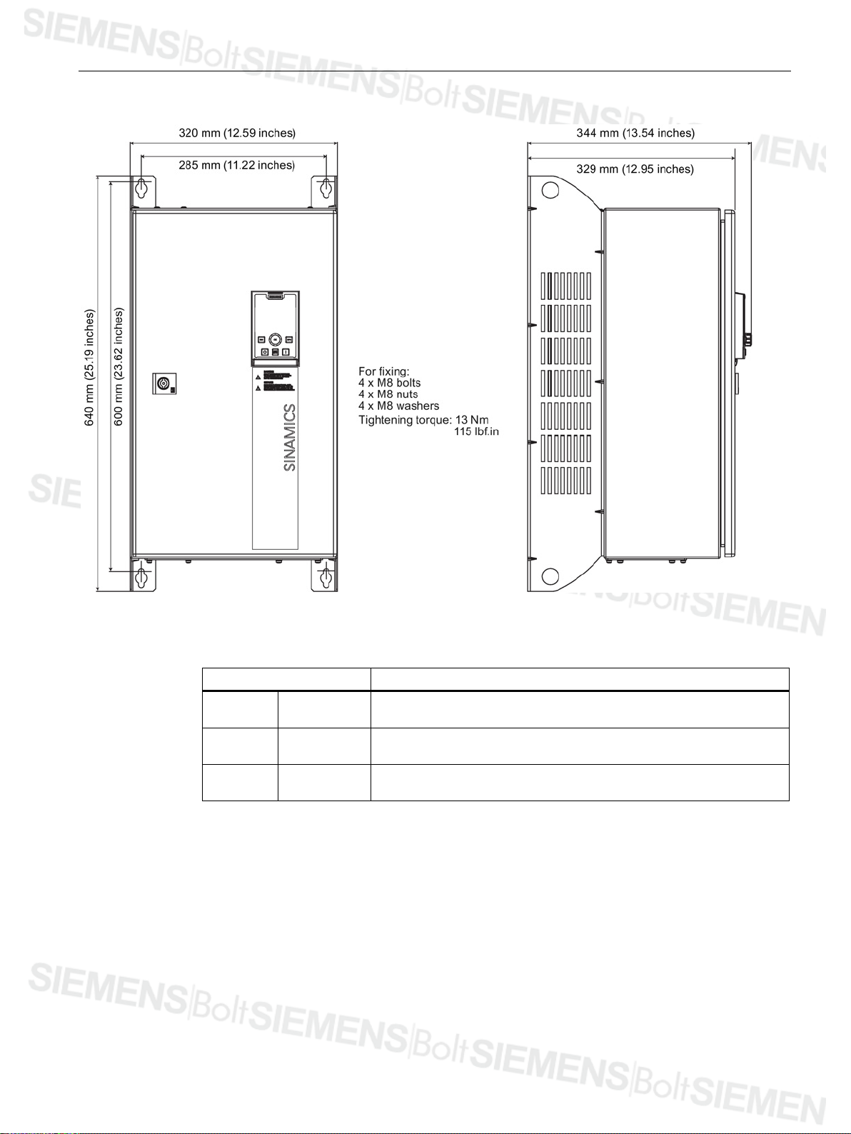
3.2 Dimensions and drill patterns
The dimension drawings for all frame sizes for the SINAMICS G120P Power Module PM230
are shown in the figures and not true to scale.
Figure 3-1 Dimensions and drill pattern, PM230 FSA (0.37 - 3.0 kW)
PM230 Power Module IP55
22 Hardware Installation Manual, 11/2014, A5E35319202B AA
Table 3- 3 Minimum distances for mounting
side by
above 100 mm
below 100 mm
0 mm

Installing / mounting
Minimum distances FSB
Note
side
0 inches
3.93 inches
3.93 inches
3.2 Dimensions and drill patterns
Figure 3-2 Dimensions and drill pattern, PM230 FSB (4.0 - 7.5 kW)
Table 3- 4 Minimum distances for mounting
side by
above 100 mm
below 100 mm
0 mm
PM230 Power Module IP55
Hardware Installation Manual, 11/2014, A5E35319202B AA
23

Installing / mounting
Minimum distances FSC
Note
4.92 inches
4.92 inches
3.2 Dimensions and drill patterns
Figure 3-3 Dimensions and drill pattern, PM230 FSC (11.0 - 18.5 kW)
Table 3- 5 Minimum distances for mounting
side by
side
above 125 mm
below 125 mm
PM230 Power Module IP55
0 mm
0 inches
24 Hardware Installation Manual, 11/2014, A5E35319202B AA
Installing / mounting
Minimum distances FSD
Note
side
1.97 inches
11.81 inches
11.81 inches
3.2 Dimensions and drill patterns
Figure 3-4 Dimensions and drill pattern, PM230 FSD (22.0 - 30.0 kW)
Table 3- 6 Minimum distances for mounting
side by
above 300 mm
below 300 mm
50 mm
PM230 Power Module IP55
Hardware Installation Manual, 11/2014, A5E35319202B AA
25
Installing / mounting
Minimum distances FSE
Note
side
1.97 inches
11.81 inches
11.81 inches
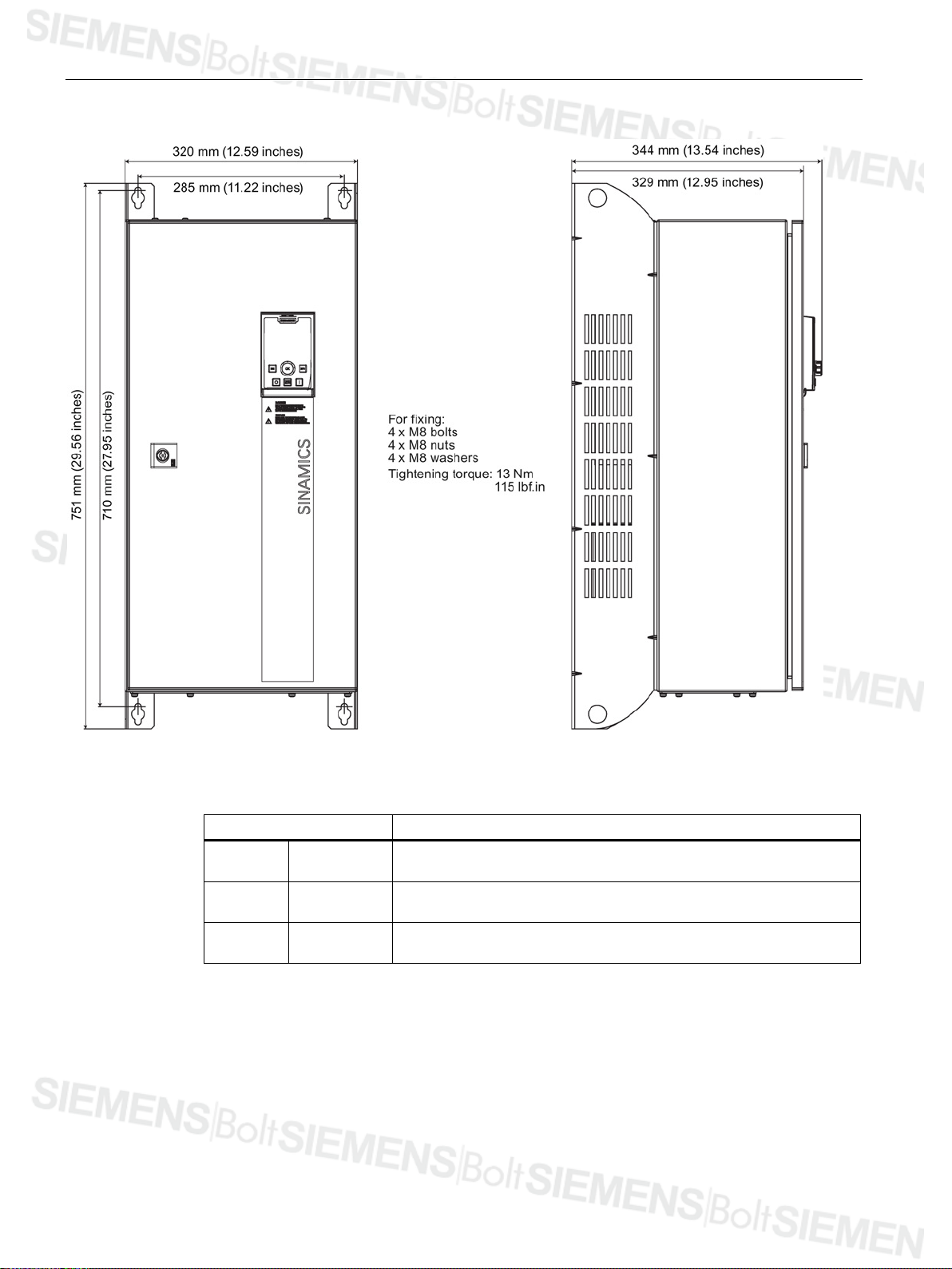
3.2 Dimensions and drill patterns
Figure 3-5 Dimensions and drill pattern, PM230 FSE (37.0 - 45.0 kW)
Table 3- 7 Minimum distances for mounting
side by
above 300 mm
below 300 mm
50 mm
PM230 Power Module IP55
26 Hardware Installation Manual, 11/2014, A5E35319202B AA
Installing / mounting
Minimum distances FSF
Note
side
1.97 inches
13.77 inches
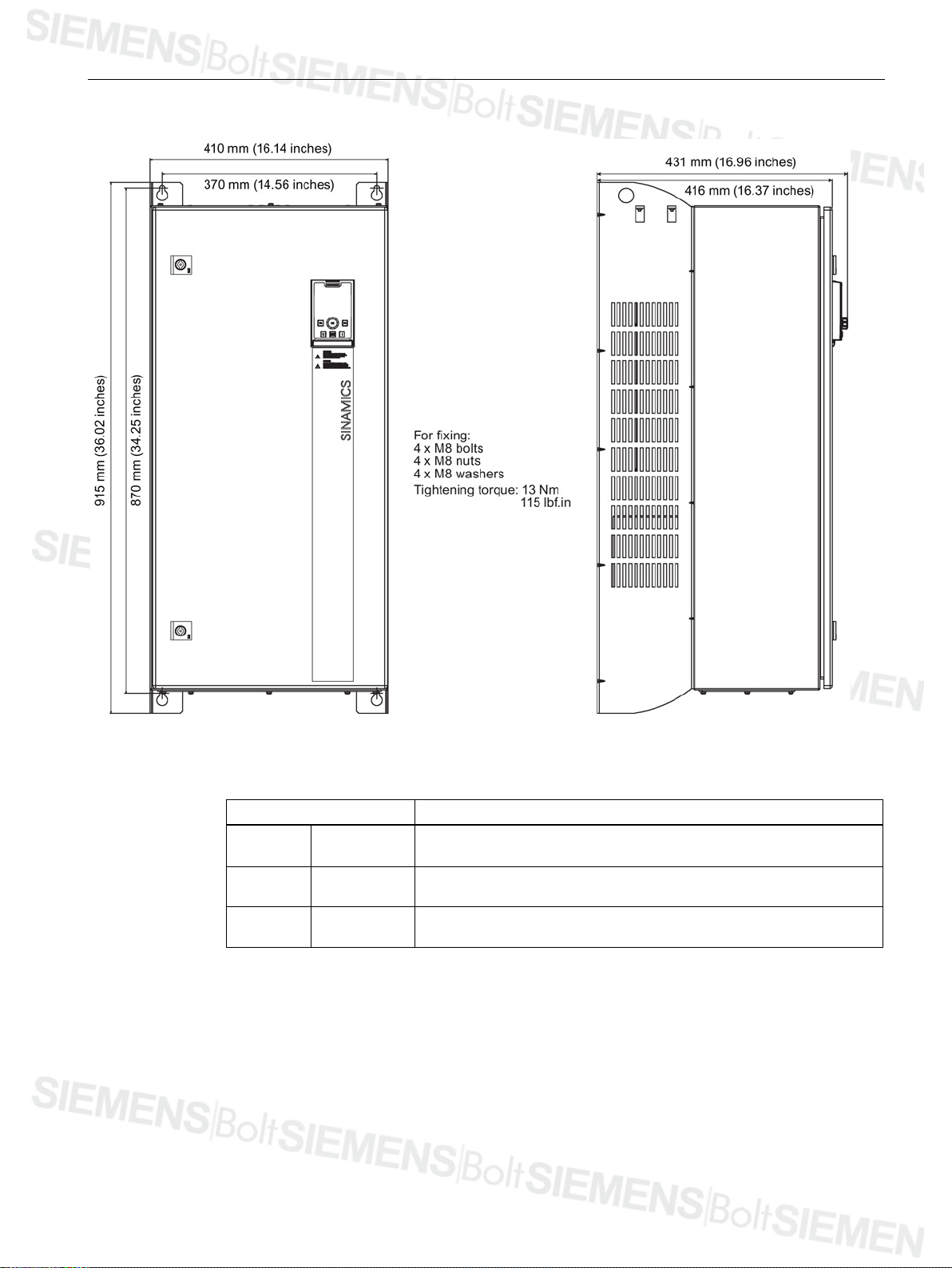
3.2 Dimensions and drill patterns
Figure 3-6 Dimensions and drill pattern, PM230 FSF (55.0 - 90.0 kW)
Table 3- 8 Minimum distances for mounting
side by
above 350 mm
50 mm
13.77 inches
below 350 mm
PM230 Power Module IP55
Hardware Installation Manual, 11/2014, A5E35319202B AA
27
Installing / mounting
Frame size
Dimensions (height x width x depth)
Fixing methods
Tightening torques
with Operator Panel
without Operator Panel
A
mm
460 x 154 x 264
460 x 154 x 249
inch
18.11 x 6.06 x 10.39
18.11 x 6.06 x 9.80
B
mm
540 x 180 x 264
540 x 180 x 249
inch
21.25 x 7.09 x 10.39
21.25 x 7.09 x 9.80
D
mm
640 x 320 x 344
640 x 320 x 329
inch
25.19 x 12.59 x 13.54
25.19 x 12.59 x 12.95
E
mm
751 x 320 x 344
751 x 320 x 329
inch
29.56 x 12.59 x 13.54
29.56 x 12.59 x 12.95
F
mm
915 x 410 x 431
915 x 410 x 416
inch
36.02 x 16.14 x 16.96
36.02 x 16.14 x 16.37
3.2 Dimensions and drill patterns
Table 3- 9 Summary of dimensions and tightening torques
4 x M4 bolts
4 x M4 nuts
4 x M4 washers
C mm 620 x 230 x 264 620 X 230 X 249 4 x M5 bolts
inch 24.40 x 9.05 x 10.39 24.40 x 9.05 x 9.80
4 x M5 nuts
4 x M5 washers
4 x M8 bolts
4 x M8 nuts
4 x M8 washers
2.5 Nm (22 lbf.in)
13.0 Nm (115 lbf.in)
PM230 Power Module IP55
28 Hardware Installation Manual, 11/2014, A5E35319202B AA
Installing / mounting
3.3
Control Unit installation
Fitting the CU to the PM FSA ... FSF
Note
Memory card
If a memory card is to be used with the Control Unit (CU), then the memory card mus
inserted into the CU prior to being fitted on the Power Module (PM). Once the CU is fitted to
the PM it is not possible to insert a memory card into the CU.
3.3 Control Unit installation
t be
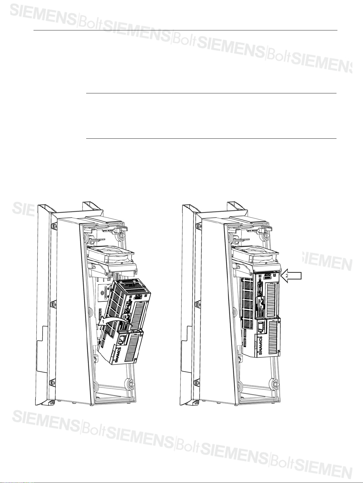
The Control Unit (CU) is snapped onto the Power Module as shown in the figure below. The
CU is fitted in the following sequence:
1. Angle the CU to allow the lower hooks of the CU to fit into the lower recesses of the
Power Module (PM).
2. Push the top of the CU towards the PM until it clicks into place.
Figure 3-7 Fitting CU to PM
PM230 Power Module IP55
Hardware Installation Manual, 11/2014, A5E35319202B AA
29
 Loading...