

SINAMICS G120D,CU250D-2 DP-F,CU250D-2 PN-F,CU250D-2 PN-F PP,CU250D-2 PN-F FO
Table of contents
 Loading...
Siemens SINAMICS G120D,CU250D-2 DP-F,CU250D-2 PN-F,CU250D-2 PN-F PP,CU250D-2 PN-F FO Original Instructions Manual


Converter with control units CU250D-2
___________________
___________________
___________________
___________________
___________________
___________________
___________________
___________________
___________________
___________________
___________________
___________________
___________________
___________________
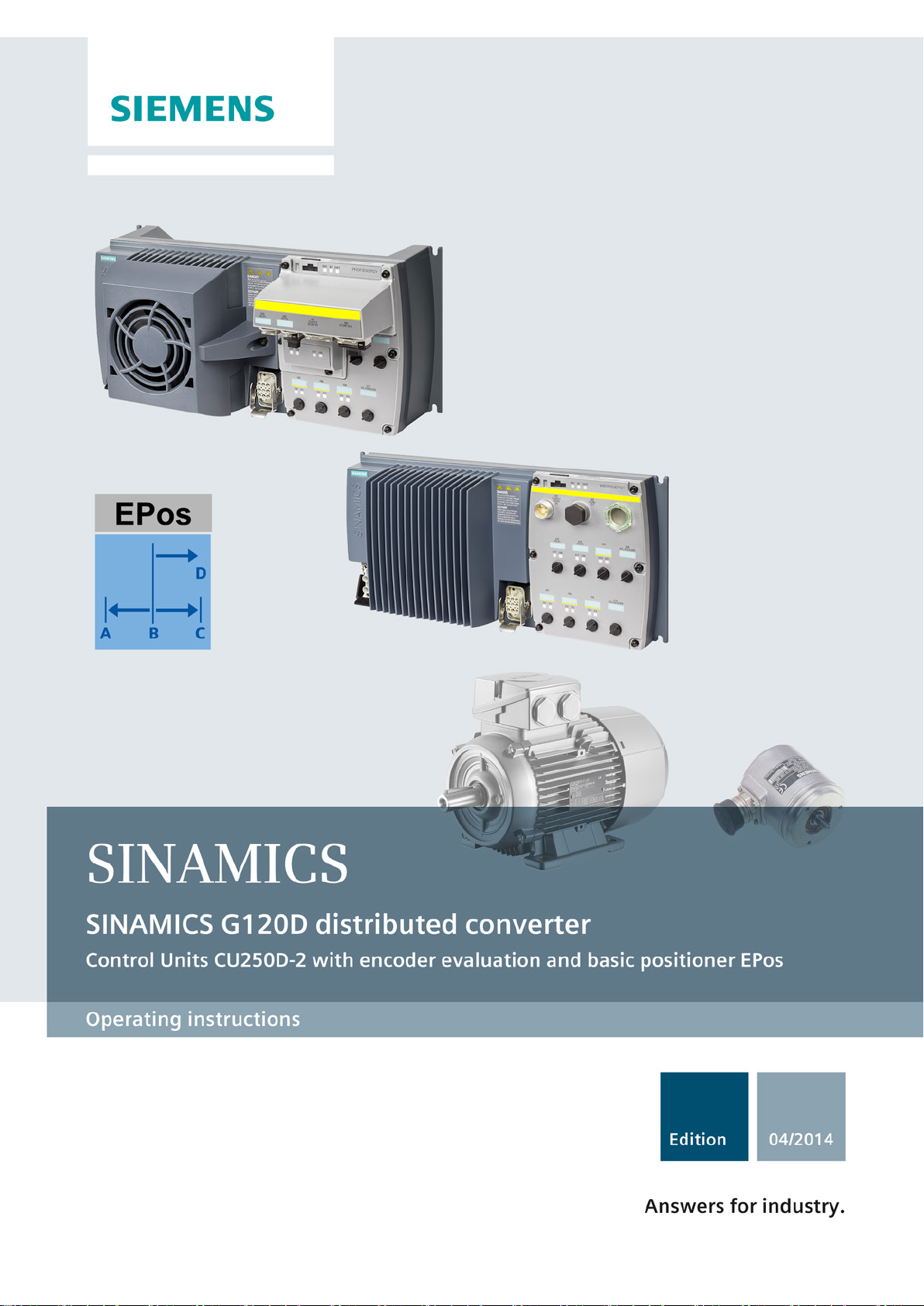
SINAMICS
SINAMICS G120D
Converter with control units
CU250D-2
Operating Instructions
Edition 04/2014, Firmware V4.7
Original instructions
04/2014, FW V4.7
A5E34261542B AA
Changes in this manual
Fundamental safety
instructions
1
Introduction
2
Description
3
Installation
4
Commissioning
5
Adapt inputs and outputs
6
Configuring the fieldbus
7
Setting functions
8
Backing up data and series
commissioning
9
Corrective maintenance
10
Alarms, faults and system
messages
11
Technical data
12
Appendix
A

Siemens AG
Industry Sector
Postfach 48 48
90026 NÜRNBERG
GERMANY
A5E34261542B AA
Ⓟ
Copyright © Siemens AG 2012 - 2014.
All rights reserved
Legal information
Warning notice system
DANGER
indicates that death or severe personal injury will result if proper precautions are not taken.
WARNING
indicates that death or severe personal injury may result if proper precautions are not taken.
CAUTION
indicates that minor personal injury can result if proper precautions are not taken.
NOTICE
indicates that property damage can result if proper precautions are not taken.
Qualified Personnel
personnel qualified
Proper use of Siemens products
WARNING
Siemens products may only be used for the applications described in the catalog and in the relevant technical
maintenance are required to ensure that the products operate safely and without any problems. The permissible
ambient conditions must be complied with. The information in the relevant documentation must be observed.
Trademarks
Disclaimer of Liability
This manual contains notices you have to observe in order to ensure your personal safety, as well as to prevent
damage to property. The notices referring to your personal safety are highlighted in the manual by a safety alert
symbol, notices referring only to property damage have no safety alert symbol. These notices shown below are
graded according to the degree of danger.
If more than one degree of danger is present, the warning notice representing the highest degree of danger will
be used. A notice warning of injury to persons with a safety alert symbol may also include a warning relating to
property damage.
The product/system described in this documentation may be operated only by
task in accordance with the relevant documentation, in particular its warning notices and safety instructions.
Qualified personnel are those who, based on their training and experience, are capable of identifying risks and
avoiding potential hazards when working with these products/systems.
for the specific
Note the following:
documentation. If products and components from other manufacturers are used, these must be recommended
or approved by Siemens. Proper transport, storage, installation, assembly, commissioning, operation and
All names identified by ® are registered trademarks of Siemens AG. The remaining trademarks in this publication
may be trademarks whose use by third parties for their own purposes could violate the rights of the owner.
We have reviewed the contents of this publication to ensure consistency with the hardware and software
described. Since variance cannot be precluded entirely, we cannot guarantee full consistency. However, the
information in this publication is reviewed regularly and any necessary corrections are included in subsequent
editions.
07/2014 Subject to change

Changes in this manual
Important changes with respect to the Manual, 01/2013 Edition
New hardware
in Chapter
Connections and cables (Page 36)
New Firmware Functions for V4.7
In Chapter
limit in the case of high-inertia starting.
(Page 209)
(I&M1 … 4)
(I&M) (Page 310)
Revised descriptions
In Chapter
(Page 237)
Corrections
in Chapter
±15 %, but rather -15 % / +20 %.
(Page 325)
New CU250D-2 PN-F FO Control Units with fieldbus via
fiber-optic cable
Reducing the pulse frequency and increasing the current
Supporting the identification & maintenance data
An overview of all the new and changed functions in the V4.7 firmware can be found in
Section New and extended functions (Page 337).
STO safety function Safe Torque Off (STO) safety function
The tolerance of the 24 V power supply of the inverter is not
The current carrying capacity of connector X01 is not 7 A,
but rather 8 A.
SINAMICS G120D CU250D-2 Inverter
(Page 23)
Inverter temperature monitoring
Identification & maintenance data
Performance ratings Control Unit
Cascading of the 24 V supply
(Page 51)
Converter with control units CU250D-2
Operating Instructions, 04/2014, FW V4.7, A5E34261542B AA
5

Changes in this manual
Converter with control units CU250D-2
6 Operating Instructions, 04/2014, FW V4.7, A5E34261542B AA

Table of contents
Changes in this manual ........................................................................................................................... 5
1 Fundamental safety instructions ............................................................................................................ 13
2 Introduction ........................................................................................................................................... 21
3 Description ............................................................................................................................................ 23
4 Installation ............................................................................................................................................ 29
5 Commissioning ..................................................................................................................................... 55
1.1 General safety instructions .......................................................................................................... 13
1.2 Safety instructions for electromagnetic fields (EMF) ................................................................... 17
1.3 Handling electrostatic sensitive devices (ESD) ........................................................................... 17
1.4 Industrial security ......................................................................................................................... 18
1.5 Residual risks of power drive systems ......................................................................................... 19
2.1 About this manual ........................................................................................................................ 21
2.2 Guide through this manual ........................................................................................................... 22
3.1 SINAMICS G120D CU250D-2 Inverter ........................................................................................ 23
3.2 Commissioning tools .................................................................................................................... 25
3.3 Supported motor series ................................................................................................................ 27
4.1 Mechanical Installation ................................................................................................................. 29
4.1.1 Drill pattern SINAMICS G120D .................................................................................................... 30
4.2 Electrical Installation .................................................................................................................... 32
4.2.1 Permissible line supplies .............................................................................................................. 32
4.2.2 Electrical data ............................................................................................................................... 33
4.2.3 Basic EMC Rules ......................................................................................................................... 34
4.2.4 Overview of the interfaces ........................................................................................................... 35
4.2.5 Connections and cables ............................................................................................................... 36
4.2.6 Connecting the motor holding brake ............................................................................................ 44
4.2.7 Factory settings of the inputs and outputs ................................................................................... 45
4.2.8 Default settings of inputs and outputs .......................................................................................... 46
4.2.9 Connecting the PROFINET interface ........................................................................................... 46
4.2.10 Encoders examples ..................................................................................................................... 47
4.2.11 Grounding converter and motor ................................................................................................... 47
4.2.12 Cable protection and cascading of the 400 V supply................................................................... 49
4.2.13 Cascading of the 24 V supply ...................................................................................................... 51
4.2.14 Connections and interference suppression ................................................................................. 51
4.2.15 Equipotential bonding .................................................................................................................. 52
5.1 Commissioning guidelines ........................................................................................................... 55
5.2 Preparing for commissioning ....................................................................................................... 57
5.2.1 Which motor fits the converter? ................................................................................................... 58
Converter with control units CU250D-2
Operating Instructions, 04/2014, FW V4.7, A5E34261542B AA
7

Table of contents
6 Adapt inputs and outputs ...................................................................................................................... 79
7 Configuring the fieldbus ........................................................................................................................ 85
5.2.2 Introduction, V/f control, vector control ....................................................................................... 58
5.2.3 Defining additional requirements for the application ................................................................... 60
5.2.4 Encoder assignment ................................................................................................................... 60
5.3 Restoring the factory setting ....................................................................................................... 62
5.4 Basic commissioning with IOP .................................................................................................... 64
5.5 Basic commissioning with STARTER ......................................................................................... 68
5.5.1 Generating a STARTER project .................................................................................................. 69
5.5.2 Transfer inverters connected via USB into the project ............................................................... 69
5.5.3 Configuring a drive ...................................................................................................................... 71
5.5.4 Carry-out basic commissioning ................................................................................................... 72
5.5.5 Adapting the encoder data .......................................................................................................... 75
5.5.6 Loading the configured data into the drive .................................................................................. 76
5.5.7 Identifying motor data .................................................................................................................. 76
6.1 Digital inputs ................................................................................................................................ 80
6.2 Fail-safe digital input ................................................................................................................... 81
6.3 Digital outputs ............................................................................................................................. 83
7.1 Fieldbus versions of the Control Unit .......................................................................................... 85
7.2 Communication via PROFINET .................................................................................................. 86
7.2.1 What do you need for communication via PROFINET? ............................................................. 87
7.2.2 Integrating converters into PROFINET ....................................................................................... 88
7.2.3 Configuring communication to the control ................................................................................... 88
7.2.4 Select telegram ........................................................................................................................... 89
7.2.5 Activating diagnostics via the control .......................................................................................... 90
7.3 Communication via PROFIBUS .................................................................................................. 91
7.3.1 What do you need for communication via PROFIBUS? ............................................................. 91
7.3.2 Integrating the inverter in PROFIBUS ......................................................................................... 91
7.3.3 Configuring the communication using SIMATIC S7 control ........................................................ 92
7.3.4 Setting the address ..................................................................................................................... 92
7.3.5 Select telegram ........................................................................................................................... 93
7.4 PROFIdrive profile for PROFIBUS and PROFINET ................................................................... 94
7.4.1 Cyclic communication ................................................................................................................. 94
7.4.1.1 Positioner: Cyclic communication ............................................................................................... 94
7.4.1.2 Control and status word 1 ........................................................................................................... 97
7.4.1.3 Control and status word 2 ........................................................................................................... 99
7.4.1.4 Control and status word for the positioner ................................................................................ 100
7.4.1.5 Control and status word 1 for the positioner ............................................................................. 102
7.4.1.6 Control and status word 2 for the positioner ............................................................................. 104
7.4.1.7 Control word block selection ..................................................................................................... 106
7.4.1.8 Control word MDI mode ............................................................................................................ 107
7.4.1.9 Status word messages .............................................................................................................. 108
7.4.1.10 Function block FB283 ............................................................................................................... 109
7.4.1.11 Extend telegrams and change signal interconnection .............................................................. 109
7.4.1.12 Slave-to-slave communication .................................................................................................. 110
7.4.2 Acyclic communication .............................................................................................................. 110
Converter with control units CU250D-2
8 Operating Instructions, 04/2014, FW V4.7, A5E34261542B AA

Table of contents
8 Setting functions ................................................................................................................................. 111
8.1 Overview of the converter functions........................................................................................... 111
8.2 Inverter control ........................................................................................................................... 113
8.2.1 Switching the motor on and off .................................................................................................. 113
8.2.2 Running the motor in jog mode (JOG function) ......................................................................... 115
8.2.3 Switching over the inverter control (command data set)............................................................ 117
8.3 Setpoints .................................................................................................................................... 119
8.3.1 Overview .................................................................................................................................... 119
8.3.2 Specifying the setpoint via the fieldbus ...................................................................................... 120
8.3.3 Motorized potentiometer as setpoint source .............................................................................. 120
8.3.4 Fixed speed as setpoint source ................................................................................................. 123
8.4 Setpoint calculation .................................................................................................................... 126
8.4.1 Overview of setpoint preparation ............................................................................................... 126
8.4.2 Invert setpoint ............................................................................................................................. 127
8.4.3 Inhibit direction of rotation .......................................................................................................... 128
8.4.4 Skip frequency bands and minimum speed ............................................................................... 129
8.4.5 Speed limitation.......................................................................................................................... 130
8.4.6 Ramp-function generator ........................................................................................................... 131
8.5 Motor control .............................................................................................................................. 136
8.5.1 V/f control ................................................................................................................................... 136
8.5.1.1 Characteristics of U/f control ...................................................................................................... 137
8.5.1.2 Selecting the U/f characteristic .................................................................................................. 138
8.5.1.3 Optimizing with a high break loose torque and brief overload ................................................... 138
8.5.2 Vector control ............................................................................................................................. 140
8.5.2.1 Checking the encoder signal ...................................................................................................... 141
8.5.2.2 Select motor control ................................................................................................................... 141
8.5.2.3 Optimizing the speed controller ................................................................................................. 142
8.5.2.4 Advanced settings ...................................................................................................................... 144
8.5.3 Operating the converter without position controller ................................................................... 145
8.6 Basic positioner and position control ......................................................................................... 147
8.6.1 Basic positioner and position control ......................................................................................... 147
8.6.2 Commissioning sequence .......................................................................................................... 148
8.6.3 Normalizing the encoder signal.................................................................................................. 149
8.6.3.1 Define the resolution .................................................................................................................. 149
8.6.3.2 Modulo range setting ................................................................................................................. 151
8.6.3.3 Checking the actual position value ............................................................................................ 153
8.6.3.4 Setting the backlash ................................................................................................................... 154
8.6.4 Limiting the positioning range .................................................................................................... 156
8.6.5 Setting the position controller ..................................................................................................... 158
8.6.5.1 Precontrol and gain .................................................................................................................... 158
8.6.5.2 Optimizing the position controller ............................................................................................... 159
8.6.5.3 Limiting the traversing profile ..................................................................................................... 162
8.6.6 Setting the monitoring functions................................................................................................. 164
8.6.6.1 Standstill and positioning monitoring ......................................................................................... 164
8.6.6.2 Following error monitoring ......................................................................................................... 166
8.6.6.3 Cam sequencer .......................................................................................................................... 168
8.6.7 Referencing ................................................................................................................................ 169
8.6.7.1 Referencing methods ................................................................................................................. 169
8.6.7.2 Setting the reference point approach ......................................................................................... 170
Converter with control units CU250D-2
Operating Instructions, 04/2014, FW V4.7, A5E34261542B AA
9

Table of contents
9 Backing up data and series commissioning .......................................................................................... 257
8.6.7.3 Setting the flying referencing..................................................................................................... 176
8.6.7.4 Set reference point .................................................................................................................... 181
8.6.7.5 Absolute encoder adjustment ................................................................................................... 183
8.6.8 Jogging ...................................................................................................................................... 185
8.6.8.1 Jog velocity................................................................................................................................ 185
8.6.8.2 Incremental jogging ................................................................................................................... 186
8.6.8.3 Setting jogging .......................................................................................................................... 186
8.6.9 Traversing blocks ...................................................................................................................... 188
8.6.9.1 Travel to fixed stop .................................................................................................................... 196
8.6.9.2 Examples................................................................................................................................... 201
8.6.10 Direct setpoint input (MDI) ........................................................................................................ 203
8.7 Protection and monitoring functions .......................................................................................... 209
8.7.1 Inverter temperature monitoring ................................................................................................ 209
8.7.2 Motor temperature monitoring using a temperature sensor ...................................................... 212
8.7.3 Protecting the motor by calculating the motor temperature ...................................................... 215
8.7.4 Overcurrent protection .............................................................................................................. 217
8.8 Application-specific functions .................................................................................................... 218
8.8.1 Functions that match the application ........................................................................................ 218
8.8.2 Unit changeover ........................................................................................................................ 219
8.8.2.1 Changing over the motor standard ........................................................................................... 220
8.8.2.2 Changing over the unit system ................................................................................................. 221
8.8.2.3 Switching units with STARTER ................................................................................................. 222
8.8.3 Electrically braking the motor .................................................................................................... 224
8.8.3.1 DC braking ................................................................................................................................ 224
8.8.3.2 Braking with regenerative feedback to the line ......................................................................... 227
8.8.4 Motor holding brake .................................................................................................................. 228
8.8.5 Monitoring the load torque (system protection)......................................................................... 232
8.8.6 Load failure monitoring .............................................................................................................. 234
8.8.7 Speed deviation monitoring....................................................................................................... 235
8.9 Safe Torque Off (STO) safety function ..................................................................................... 237
8.9.1 Function description .................................................................................................................. 237
8.9.2 Prerequisite for STO use ........................................................................................................... 239
8.9.3 Commissioning STO ................................................................................................................. 239
8.9.3.1 Commissioning tools ................................................................................................................. 239
8.9.3.2 Protection of the settings from unauthorized changes .............................................................. 240
8.9.3.3 Resetting the safety function parameters to the factory setting ................................................ 240
8.9.3.4 Changing settings ..................................................................................................................... 241
8.9.3.5 Interconnecting the "STO active" signal .................................................................................... 242
8.9.3.6 Setting the filter for safety-related inputs .................................................................................. 243
8.9.3.7 Setting the forced checking procedure (test stop) .................................................................... 246
8.9.3.8 Activate settings ........................................................................................................................ 247
8.9.3.9 Checking the assignment of the digital inputs........................................................................... 248
8.9.3.10 Acceptance - completion of commissioning .............................................................................. 250
8.10 Switchover between different settings ...................................................................................... 254
9.1 Saving settings on a memory card ............................................................................................ 258
9.1.1 Saving settings to the memory card .......................................................................................... 259
9.1.2 Transferring the settings from the memory card ....................................................................... 260
9.1.3 Safely remove the memory card ............................................................................................... 261
Converter with control units CU250D-2
10 Operating Instructions, 04/2014, FW V4.7, A5E34261542B AA

Table of contents
10 Corrective maintenance ...................................................................................................................... 275
11 Alarms, faults and system messages .................................................................................................. 299
12 Technical data .................................................................................................................................... 325
9.2 Backing up and transferring settings using STARTER .............................................................. 263
9.3 Saving settings and transferring them using an operator panel ................................................ 265
9.4 Other ways to back up settings .................................................................................................. 266
9.5 Write and know-how protection .................................................................................................. 267
9.5.1 Write protection .......................................................................................................................... 267
9.5.2 Know-how protection ................................................................................................................. 269
9.5.2.1 Settings for the know-how protection ......................................................................................... 271
9.5.2.2 Creating an exception list for the know-how protection ............................................................. 273
10.1 Spare parts - external fan .......................................................................................................... 275
10.2 Overview of replacing converter components ............................................................................ 276
10.3 Replacing a Control Unit with enabled safety function .............................................................. 278
10.4 Replacing the Control Unit without the safety functions enabled .............................................. 282
10.5 Replacing the Control Unit without data backup ........................................................................ 284
10.6 Replacing a Control Unit with active know-how protection ........................................................ 285
10.7 Replacing a Power Module with enabled safety function .......................................................... 287
10.8 Replacing a Power Module without the safety function being enabled ..................................... 288
10.9 Upgrading firmware .................................................................................................................... 289
10.10 Firmware downgrade ................................................................................................................. 292
10.11 Correcting a failed firmware upgrade or downgrade.................................................................. 295
10.12 Reduced acceptance test after component replacement .......................................................... 296
10.13 If the converter no longer responds ........................................................................................... 297
11.1 Alarms ........................................................................................................................................ 299
11.2 Faults ......................................................................................................................................... 303
11.3 Status LED overview .................................................................................................................. 308
11.4 Identification & maintenance data (I&M) .................................................................................... 310
11.5 System runtime .......................................................................................................................... 311
11.6 List of alarms and faults ............................................................................................................. 312
12.1 Performance ratings Control Unit ............................................................................................... 325
12.2 Performance ratings Power Module........................................................................................... 327
12.3 SINAMICS G120D specifications ............................................................................................... 328
12.4 Ambient operating conditions ..................................................................................................... 329
12.5 Current and voltage derating dependent on the installation altitude ......................................... 330
12.6 Pulse frequency and current reduction ...................................................................................... 331
Converter with control units CU250D-2
Operating Instructions, 04/2014, FW V4.7, A5E34261542B AA
11

Table of contents
A Appendix ............................................................................................................................................. 337
Index ................................................................................................................................................... 375
12.7 Standards (PM250D) ................................................................................................................ 332
12.8 Electromagnetic Compatibility ................................................................................................... 333
A.1 New and extended functions ..................................................................................................... 337
A.2 Star-delta motor connection and application examples ............................................................ 340
A.3 Parameter.................................................................................................................................. 341
A.4 Handling STARTER .................................................................................................................. 344
A.4.1 Change settings ........................................................................................................................ 344
A.4.2 Optimize the drive using the trace function ............................................................................... 346
A.5 Interconnecting signals in the inverter ...................................................................................... 349
A.5.1 Fundamentals ........................................................................................................................... 349
A.5.2 Example .................................................................................................................................... 351
A.6 Application Examples ................................................................................................................ 353
A.6.1 Setting an absolute encoder ..................................................................................................... 353
A.6.2 Go online with STARTER via PROFINET ................................................................................. 357
A.6.2.1 Adapting the PROFINET interface ............................................................................................ 357
A.6.2.2 Create a reference for STARTERS ........................................................................................... 358
A.6.2.3 Call the STARTER and go online ............................................................................................. 359
A.6.3 Connecting the safety-related input .......................................................................................... 359
A.6.4 Connecting fail-safe digital inputs ............................................................................................. 360
A.7 Setting a non standard HTL encoder ........................................................................................ 361
A.8 Setting a non standard SSI encoder ......................................................................................... 362
A.9 Acceptance tests for the safety functions ................................................................................. 365
A.9.1 Recommended acceptance test ............................................................................................... 365
A.9.2 Machine documentation ............................................................................................................ 368
A.9.3 Log the settings for the basic functions, firmware V4.4 ... V4.7 ................................................ 370
A.10 Manuals and technical support ................................................................................................. 371
A.10.1 Manuals for your inverter .......................................................................................................... 371
A.10.2 Configuring support ................................................................................................................... 372
A.10.3 Product Support ........................................................................................................................ 372
A.11 Mistakes and improvements ..................................................................................................... 373
Converter with control units CU250D-2
12 Operating Instructions, 04/2014, FW V4.7, A5E34261542B AA
1
1.1
General safety instructions
DANGER
Danger to life due to live parts and other energy sources
WARNING
Danger to life through a hazardous voltage when connecting an unsuitable power supply
Death or serious injury can result when live parts are touched.
• Only work on electrical devices when you are qualified for this job.
• Always observe the country-specific safety rules.
Generally, six steps apply when establishing safety:
1. Prepare for shutdown and notify all those who will be affected by the procedure.
2. Disconnect the machine from the supply.
– Switch off the machine.
– Wait until the discharge time specified on the warning labels has elapsed.
– Check that it really is in a no-voltage condition, from phase conductor to phase
conductor and phase conductor to protective conductor.
– Check whether the existing auxiliary supply circuits are de-energized.
– Ensure that the motors cannot move.
3. Identify all other dangerous energy sources, e.g. compressed air, hydraulic systems, or
water.
4. Isolate or neutralize all hazardous energy sources by closing switches, grounding or
short-circuiting or closing valves, for example.
5. Secure the energy sources against switching on again.
6. Ensure that the correct machine is completely interlocked.
After you have completed the work, restore the operational readiness in the inverse
Converter with control units CU250D-2
Operating Instructions, 04/2014, FW V4.7, A5E34261542B AA
sequence.
Touching live components can result in death or severe injury.
• Only use power supplies that provide SELV (Safety Extra Low Voltage) or PELV-
(Protective Extra Low Voltage) output voltages for all connections and terminals of the
electronics modules.
13
Fundamental safety instructions
WARNING
Danger to life when live parts are touched on damaged devices
WARNING
Danger to life through electric shock due to unconnected cable shields
WARNING
Danger to life due to electric shock when not grounded
WARNING
Danger to life due to electric shock when opening plug connections in operation
WARNING
Danger to life due to fire spreading if housing is inadequate
1.1 General safety instructions
Improper handling of devices can cause damage.
For damaged devices, hazardous voltages can be present at the enclosure or at exposed
components; if touched, this can result in death or severe injury.
• Ensure compliance with the limit values specified in the technical data during transport,
storage and operation.
• Do not use any damaged devices.
Hazardous touch voltages can occur through capacitive cross-coupling due to unconnected
cable shields.
• As a minimum, connect cable shields and the conductors of power cables that are not
used (e.g. brake cores) at one end at the grounded housing potential.
For missing or incorrectly implemented protective conductor connection for devices with
protection class I, high voltages can be present at open, exposed parts, which when
touched, can result in death or severe injury.
• Ground the device in compliance with the applicable regulations.
When opening plug connections in operation, arcs can result in severe injury or death.
• Only open plug connections when the equipment is in a no-voltage state, unless it has
been explicitly stated that they can be opened in operation.
Fire and smoke development can cause severe personal injury or material damage.
• Install devices without a protective housing in a metal control cabinet (or protect the
device by another equivalent measure) in such a way that contact with fire is prevented.
• Ensure that smoke can only escape via controlled and monitored paths.
Converter with control units CU250D-2
14 Operating Instructions, 04/2014, FW V4.7, A5E34261542B AA

Fundamental safety instructions
WARNING
Danger to life through unexpected movement of machines when using mobile wireless
devices or mobile phones
WARNING
Danger to life due to the motor catching fire in the event of insulation overload
WARNING
Danger to life due to fire if overheating occurs because of insufficient ventilation clearances
WARNING
Danger of an accident occurring due to missing or illegible warning labels
1.1 General safety instructions
Using mobile wireless devices or mobile phones with a transmit power > 1 W closer than
approx. 2 m to the components may cause the devices to malfunction, influence the
functional safety of machines therefore putting people at risk or causing material damage.
• Switch the wireless devices or mobile phones off in the immediate vicinity of the
components.
There is higher stress on the motor insulation through a ground fault in an IT system. If the
insulation fails, it is possible that death or severe injury can occur as a result of smoke and
fire.
• Use a monitoring device that signals an insulation fault.
• Correct the fault as quickly as possible so the motor insulation is not overloaded.
Inadequate ventilation clearances can cause overheating of components with subsequent
fire and smoke. This can cause severe injury or even death. This can also result in
increased downtime and reduced service lives for devices/systems.
• Ensure compliance with the specified minimum clearance as ventilation clearance for
the respective component.
Missing or illegible warning labels can result in accidents involving death or serious injury.
• Check that the warning labels are complete based on the documentation.
• Attach any missing warning labels to the components, in the national language if
necessary.
• Replace illegible warning labels.
Converter with control units CU250D-2
Operating Instructions, 04/2014, FW V4.7, A5E34261542B AA
15

Fundamental safety instructions
NOTICE
Device damage caused by incorrect voltage/insulation tests
WARNING
Danger to life when safety functions are inactive
Note
Important safety notices for Safety Integrated functions
If you want to use Safety In
Safety Integrated manuals.
WARNING
Danger to life or malfunctions of the machine as a result of incorrect or changed
parameterization
1.1 General safety instructions
Incorrect voltage/insulation tests can damage the device.
• Before carrying out a voltage/insulation check of the system/machine, disconnect the
devices as all converters and motors have been subject to a high voltage test by the
manufacturer, and therefore it is not necessary to perform an additional test within the
system/machine.
Safety functions that are inactive or that have not been adjusted accordingly can cause
operational faults on machines that could lead to serious injury or death.
• Observe the information in the appropriate product documentation before
commissioning.
• Carry out a safety inspection for functions relevant to safety on the entire system,
including all safety-related components.
• Ensure that the safety functions used in your drives and automation tasks are adjusted
and activated through appropriate parameterizing.
• Perform a function test.
• Only put your plant into live operation once you have guaranteed that the functions
relevant to safety are running correctly.
tegrated functions, you must observe the safety notices in the
As a result of incorrect or changed parameterization, machines can malfunction, which in
turn can lead to injuries or death.
• Protect the parameterization (parameter assignments) against unauthorized access.
• Respond to possible malfunctions by applying suitable measures (e.g. EMERGENCY
STOP or EMERGENCY OFF).
Converter with control units CU250D-2
16 Operating Instructions, 04/2014, FW V4.7, A5E34261542B AA

Fundamental safety instructions
1.2
Safety instructions for electromagnetic fields (EMF)
WARNING
Danger to life from electromagnetic fields
1.3
Handling electrostatic sensitive devices (ESD)
NOTICE
Damage through electric fields or electrostatic discharge
1.2 Safety instructions for electromagnetic fields (EMF)
Electromagnetic fields (EMF) are generated by the operation of electrical power equipment
such as transformers, converters or motors.
People with pacemakers or implants are at a special risk in the immediate vicinity of these
devices/systems.
• Ensure that the persons involved are the necessary distance away (minimum 2 m).
Electrostatic sensitive devices (ESD) are individual components, integrated circuits, modules
or devices that may be damaged by either electric fields or electrostatic discharge.
Electric fields or electrostatic discharge can cause malfunctions through damaged
individual components, integrated circuits, modules or devices.
• Only pack, store, transport and send electronic components, modules or devices in their
original packaging or in other suitable materials, e.g conductive foam rubber of
aluminum foil.
• Only touch components, modules and devices when you are grounded by one of the
following methods:
– Wearing an ESD wrist strap
– Wearing ESD shoes or ESD grounding straps in ESD areas with conductive flooring
• Only place electronic components, modules or devices on conductive surfaces (table
with ESD surface, conductive ESD foam, ESD packaging, ESD transport container).
Converter with control units CU250D-2
Operating Instructions, 04/2014, FW V4.7, A5E34261542B AA
17

Fundamental safety instructions
1.4
Industrial security
Note
Industrial security
Siemens provides products and solutions with industrial security functions that support the
secure operation of plants, solutions, machines, equipment and/or networks. They are
important components in a holistic industrial secur
products and solutions undergo continuous development. Siemens recommends strongly
that you regularly check for product updates.
For the secure operation of Siemens products and solutions, it is necessary to take su
preventive action (e.g. cell protection concept) and integrate each component into a holistic,
state
also be considered. For more information about industrial sec
(
To stay informed about product updates as they occur, sign up for a product
newsletter. For more information, visi
(
WARNING
Danger as a result of unsafe operating states resulting from software manipulation
1.4 Industrial security
ity concept. With this in mind, Siemens’
itable
-of-the-art industrial security concept. Third-party products that may be in use should
urity, visit Hotspot-Text
http://www.siemens.com/industrialsecurity).
-specific
t Hotspot-Text
http://support.automation.siemens.com).
Software manipulation (e.g. by viruses, Trojan horses, malware, worms) can cause unsafe
operating states to develop in your installation which can result in death, severe injuries
and/or material damage.
• Keep the software up to date.
You will find relevant information and newsletters at this address
(http://support.automation.siemens.com).
• Incorporate the automation and drive components into a holistic, state-of-the-art
industrial security concept for the installation or machine.
You will find further information at this address
(http://www.siemens.com/industrialsecurity).
• Make sure that you include all installed products into the holistic industrial security
concept.
Converter with control units CU250D-2
18 Operating Instructions, 04/2014, FW V4.7, A5E34261542B AA

Fundamental safety instructions
1.5
Residual risks of power drive systems
1.5 Residual risks of power drive systems
The control and drive components of a drive system are approved for industrial and
commercial use in industrial line supplies. Their use in public line supplies requires a
different configuration and/or additional measures.
These components may only be operated in closed housings or in higher-level control
cabinets with protective covers that are closed, and when all of the protective devices are
used.
These components may only be handled by qualified and trained technical personnel who
are knowledgeable and observe all of the safety instructions on the components and in the
associated technical user documentation.
When assessing the machine's risk in accordance with the respective local regulations (e.g.,
EC Machinery Directive), the machine manufacturer must take into account the following
residual risks emanating from the control and drive components of a drive system:
1. Unintentional movements of driven machine components during commissioning,
operation, maintenance, and repairs caused by, for example,
– Hardware and/or software errors in the sensors, control system, actuators, and cables
and connections
– Response times of the control system and of the drive
– Operation and/or environmental conditions outside the specification
– Condensation/conductive contamination
– Parameterization, programming, cabling, and installation errors
– Use of wireless devices/mobile phones in the immediate vicinity of the control system
– External influences/damage
2. In the event of a fault, exceptionally high temperatures, including an open fire, as well as
emissions of light, noise, particles, gases, etc. can occur inside and outside the inverter,
e.g.:
– Component failure
– Software errors
– Operation and/or environmental conditions outside the specification
– External influences/damage
Inverters of the Open Type/IP20 degree of protection must be installed in a metal control
cabinet (or protected by another equivalent measure) such that contact with fire inside
and outside the inverter is not possible.
Converter with control units CU250D-2
Operating Instructions, 04/2014, FW V4.7, A5E34261542B AA
19

Fundamental safety instructions
Note
The components must be protected against conductive contamination (e.g. by installing them
in a control cabinet with degree of protection IP54 according to IEC 60529 or NEMA 12).
Assuming that conductive contamination at the installation site can definitely be excluded, a
lower degree of cabinet protection may be permitted.
1.5 Residual risks of power drive systems
3. Hazardous shock voltages caused by, for example,
– Component failure
– Influence during electrostatic charging
– Induction of voltages in moving motors
– Operation and/or environmental conditions outside the specification
– Condensation/conductive contamination
– External influences/damage
4. Electrical, magnetic and electromagnetic fields generated in operation that can pose a
risk to people with a pacemaker, implants or metal replacement joints, etc., if they are too
close
5. Release of environmental pollutants or emissions as a result of improper operation of the
system and/or failure to dispose of components safely and correctly
For more information about residual risks of the components in a drive system, see the
relevant sections in the technical user documentation.
Converter with control units CU250D-2
20 Operating Instructions, 04/2014, FW V4.7, A5E34261542B AA

2
2.1
About this manual
Who requires the operating instructions and what for?
What is described in the operating instructions?
What is the meaning of the symbols in the manual?
An operating instruction starts here.
This concludes the operating instru
The subsequent text is applicable for an operator panel.
Th
Exampl
The description of the corresponding inverter function starts with one
of these symbols.
See also:
These operating instructions primarily address fitters, commissioning engineers and machine
operators. The operating instructions describe the devices and device components and
enable the target groups being addressed to install, connect-up, set, and commission the
converters safely and in the correct manner.
These operating instructions provide a summary of all of the information required to operate
the converter under normal, safe conditions.
The information provided in the operating instructions has been compiled in such a way that
it is sufficient for all standard applications and enables drives to be commissioned as
efficiently as possible. Where it appears useful, additional information for entry level
personnel has been added.
The operating instructions also contain information about special applications. Since it is
assumed that readers already have a sound technical knowledge of how to configure and
parameterize these applications, the relevant information is summarized accordingly. This
relates, e.g. to operation with fieldbus systems and safety-related applications.
e following text applies if you are using a PC with STARTER.
es of the inverter-function symbols
Overview of the converter functions (Page 111).
ction.
Converter with control units CU250D-2
Operating Instructions, 04/2014, FW V4.7, A5E34261542B AA
21
Introduction
2.2
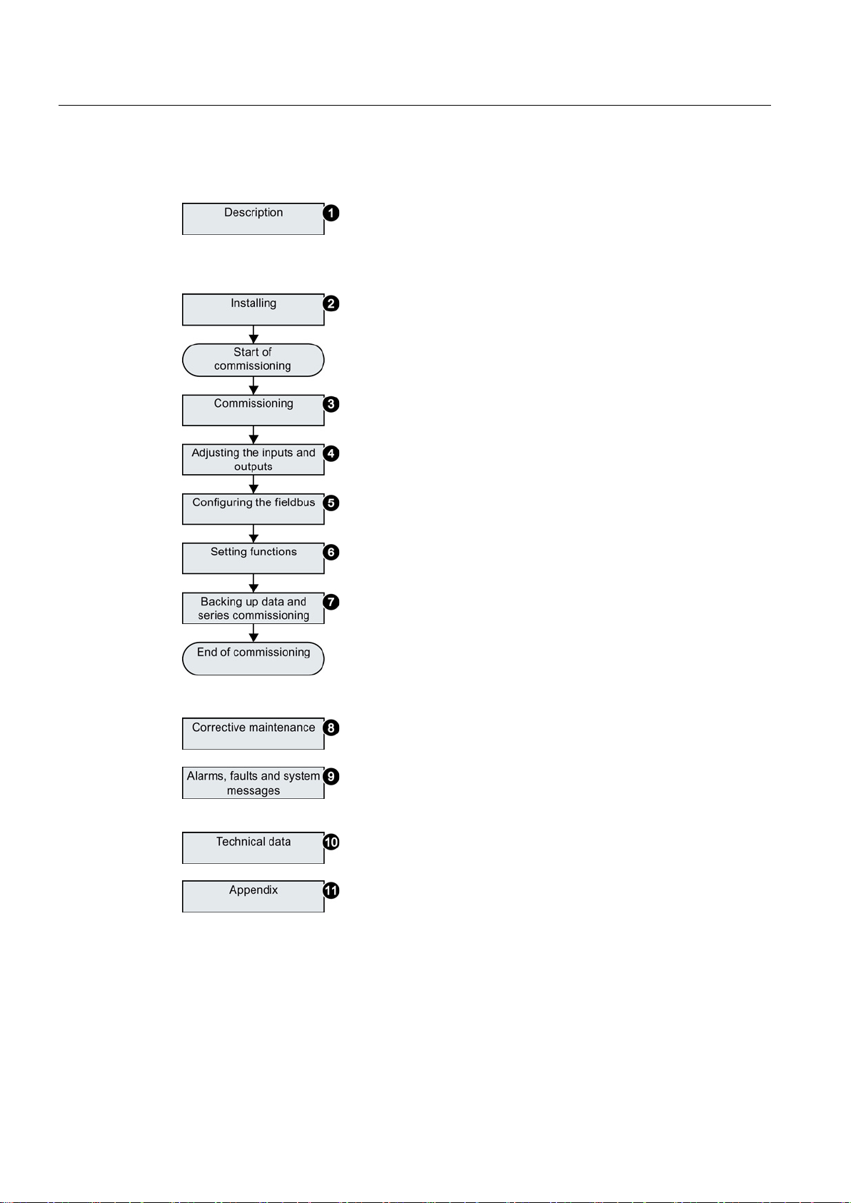
Guide through this manual
①
Inverter components and accessories.
Permissible motors.
Tools for commissioning.
②
Install and wire the inverter and its components.
Install the inverter in accordance with EMC.
③
Prepare for commissioning.
Restore the inverter to factory settings.
Define the inverter’s basic settings.
④
Adjust the function of the inputs and outputs.
⑤
Configure communication via PROFIBUS or PROFINET.
Communicati
"Fieldbus" function manual; see also:
support (Page 371).
⑥
Set up the funct
and protection functions.
⑦
Backup the inverter’s settings to an external data storage
medium, e.g. a memory card or an operator panel.
⑧
Replace the inverter and its components.
Firmware update.
⑨
Meaning of the LEDs on the front of the inverter.
System runtime.
Faults and warnings.
⑩
The most important technical data of the inverter.
⑪
Setting up the new inverter functions.
Application examples.
2.2 Guide through this manual
on using other fieldbuses can be found in the
ions, e.g. setpoint processing, motor control
Manuals and technical
Converter with control units CU250D-2
22 Operating Instructions, 04/2014, FW V4.7, A5E34261542B AA
3
Use for the intended purpose
3.1
SINAMICS G120D CU250D-2 Inverter
Overview
Designation
Interface
Encoder type
Order number
SSI Absolute Encoder
Push-Pull connections
The inverter described in this manual is a device for controlling an induction motor. The
inverter is designed for installation in electrical installations or machines.
It has been approved for industrial and commercial use on industrial networks. Additional
measures have to be taken when connected to public grids.
The technical specifications and information about connection conditions are indicated on
the rating plate and in the operating instructions.
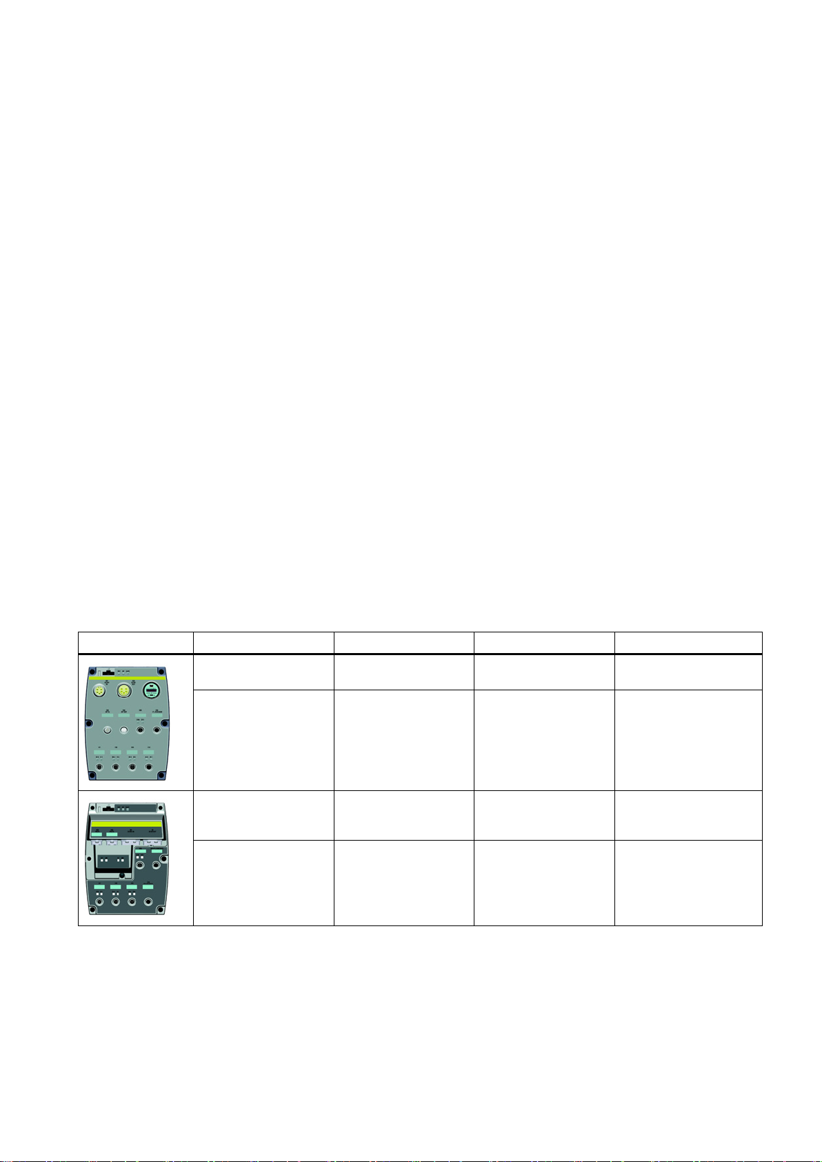
The SINAMICS G120D is a converter for controlling the position of a drive. The converter
consists of two parts, the Control Unit (CU) and the Power Module (PM).
Table 3- 1 CU250D-2 Control Units
CU250D-2 DP-F PROFIBUS HTL Encoder
CU250D-2 PN-F PROFINET,
CU250D-2 PN-F PP PROFINET,
CU250D-2 PN-F FO PROFINET,
EtherNet/IP
EtherNet/IP
EtherNet/IP
Fibre optic connections
HTL Encoder
SSI Absolute Encoder
HTL Encoder
SSI Absolute Encoder
HTL Encoder
SSI Absolute Encoder
6SL3546-0FB21-1PA0
6SL3546-0FB21-1FA0
6SL3546-0FB21-1FB0
6SL3546-0FB21-1FC0
Converter with control units CU250D-2
Operating Instructions, 04/2014, FW V4.7, A5E34261542B AA
23

Description
Frame
size
Rated output
power
Rated output
current
Order number
based on High Overload (HO)
0.75 kW
2.2 A
6SL3525-0PE17-5AA1
4.0 kW
10.2 A
6SL3525-0PE24-0AA1
5.5 kW
13.2 A
6SL3525-0PE25-5AA1
3.1 SINAMICS G120D CU250D-2 Inverter
Table 3- 2 PM250D Power Modules
FSA
1.5 kW 4.1 A 6SL3525-0PE21-5AA1
FSB 3.0 kW 7.7 A 6SL3525-0PE23-0AA1
FSC
7.5 kW 19.0 A 6SL3525-0PE27-5AA1
Converter with control units CU250D-2
24 Operating Instructions, 04/2014, FW V4.7, A5E34261542B AA
Description
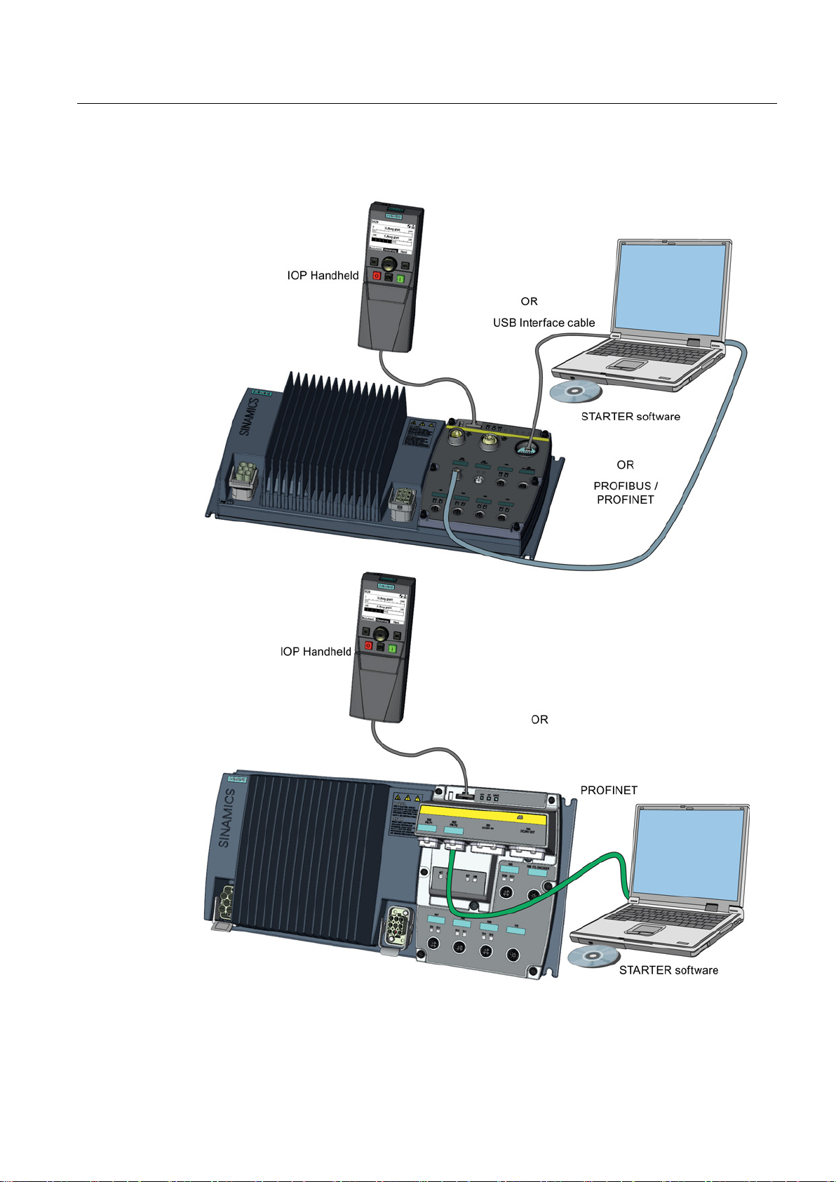
3.2
Commissioning tools
3.2 Commissioning tools
Figure 3-1 Commissioning tools - PC or IOP Handheld Kit
Converter with control units CU250D-2
Operating Instructions, 04/2014, FW V4.7, A5E34261542B AA
25

Description
Component or tool
Order number
Operator Panel
IOP Handheld
6SL3255-0AA00-4HA0
ns.com/WW/view/en/26233208)
PC Connection Kit
Comprising USB cable (3 m).
6SL3255-0AA00-2CA0
Memory cards
3.2 Commissioning tools
Table 3- 3 Components and tools for commissioning
STARTER Commissioning tool (PC
software)
You obtain STARTER on a DVD
(Order number: 6SL30720AA00-0AG0)
and it can be downloaded:
Download STARTER
(http://support.automation.sieme
The following memory cards are available as medium to back up converter settings:
● Card without firmware: Order No. 6SL3054-4AG00-2AA0.
● Card with firmware: Order No. 6SL3054-7Ex00-2BA0.
The digit at position x designates the firmware version:
4.6 ≙ EG, 4.7 ≙ EH
Converter with control units CU250D-2
26 Operating Instructions, 04/2014, FW V4.7, A5E34261542B AA
Description
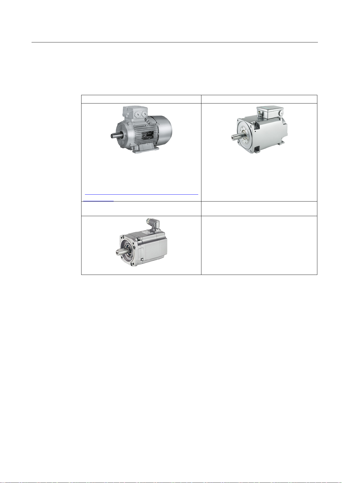
3.3
Supported motor series
SIMOTICS GP, SIMOTICS SD IEC motors
SIMOTICS M main motors
en/84049346).
On request: Encoderless permanently excited
synchronous motors SIMOTICS S
Motors from other manufacturers
3.3 Supported motor series
The inverter is designed for the following motor series:
1LG6, 1LA7, 1LA9 and 1LE1 standard induction
motors
Multi-motor drive is permissible, i.e. multiple
motors operated on one inverter. See also: Multimotor drive
(http://support.automation.siemens.com/WW/view/
1FK7 synchronous motors
1PH8 induction motors
Standard induction motors
Converter with control units CU250D-2
Operating Instructions, 04/2014, FW V4.7, A5E34261542B AA
27

Description
3.3 Supported motor series
Converter with control units CU250D-2
28 Operating Instructions, 04/2014, FW V4.7, A5E34261542B AA
4
4.1
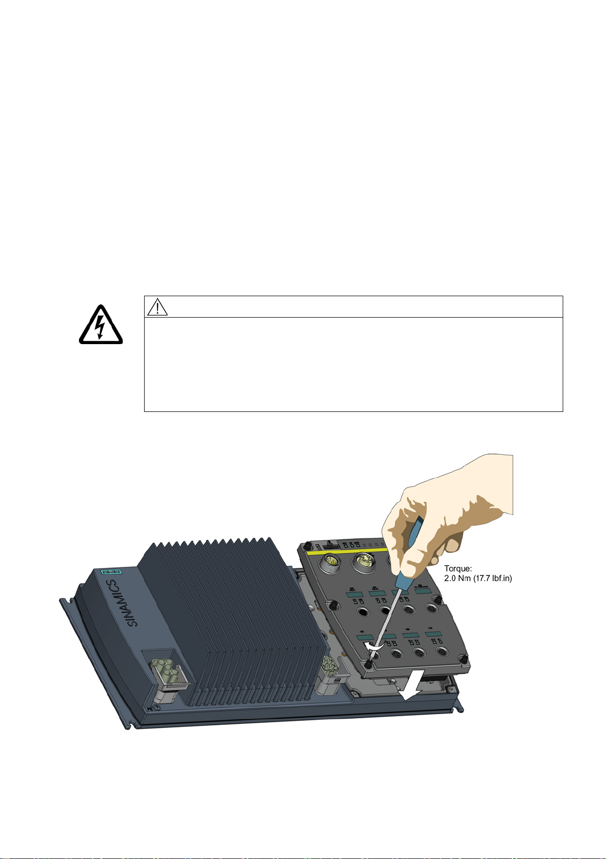
Mechanical Installation
Fitting the Control Unit to the Power Module
CAUTION
Seals fitted correctly
TN and TT mains supplies
The inverter is delivered as two separate components - the Power Module (PM) and the
Control Unit (CU). The CU must be fitted to the PM prior to any further commissioning taking
place.
It is important that when assembling the Power Module and the Control Unit that all the
seals are fitted correctly to ensure IP65 rating.
The SINAMICS PM250D Power Module with the Class A integrated mains filter is only
suitable for operation on TN and TT mains supplies.
The CU is fitted to the PM as shown in the diagram below.
Figure 4-1 Fitting the Control Unit to the Power Module
Converter with control units CU250D-2
Operating Instructions, 04/2014, FW V4.7, A5E34261542B AA
29

Installation
4.1.1
Drill pattern SINAMICS G120D
Drill pattern and dimensions
4.1 Mechanical Installation
The inverter has an identical drill pattern for all frame sizes. The drill pattern, depth and
tightening torques are shown in the diagram below.
Figure 4-2 SINAMICS G120D drill pattern
Converter with control units CU250D-2
30 Operating Instructions, 04/2014, FW V4.7, A5E34261542B AA
Loading...