

Page 1
Page 2

Page 3

Converter with control units CU250D-2
___________________
___________________
___________________
___________________
___________________
___________________
___________________
___________________
___________________
___________________
___________________
___________________
___________________
SINAMICS
SINAMICS G120D
Converter with control units
CU250D-2
Operating Instructions
Edition 04/2015, Firmware V4.7.3
Original instructions
04/2015, FW V4.7.3
A5E34261542B AB
Changes in this manual
Fundamental safety
instructions
1
Introduction
2
Description
3
Installation
4
Commissioning
5
Adapt fieldbus configuration
6
Advanced commissioning
7
Backing up data and series
commissioning
8
Corrective maintenance
9
Alarms, faults and system
messages
10
Technical data
11
Appendix
A
Page 4

Siemens AG
Division Digital Factory
Postfach 48 48
90026 NÜRNBERG
GERMANY
A5E34261542B AB
Ⓟ
Copyright © Siemens AG 2012 - 2015.
All rights reserved
Legal information
Warning notice system
DANGER
indicates that death or severe personal injury will result if proper precautions are not taken.
WARNING
indicates that death or severe personal injury may result if proper precautions are not taken.
CAUTION
indicates that minor personal injury can result if proper precautions are not taken.
NOTICE
indicates that property damage can result if proper precautions are not taken.
Qualified Personnel
personnel qualified
Proper use of Siemens products
WARNING
Siemens products may only be used for the applications described in the catalog and in the relevant technical
maintenance are required to ensure that the products operate safely and without any problems. The permissible
ambient conditions must be complied with. The information in the relevant documentation must be observed.
Trademarks
Disclaimer of Liability
This manual contains notices you have to observe in order to ensure your personal safety, as well as to prevent
damage to property. The notices referring to your personal safety are highlighted in the manual by a safety alert
symbol, notices referring only to property damage have no safety alert symbol. These notices shown below are
graded according to the degree of danger.
If more than one degree of danger is present, the warning notice representing the highest degree of danger will
be used. A notice warning of injury to persons with a safety alert symbol may also include a warning relating to
property damage.
The product/system described in this documentation may be operated only by
task in accordance with the relevant documentation, in particular its warning notices and safety instructions.
Qualified personnel are those who, based on their training and experience, are capable of identifying risks and
avoiding potential hazards when working with these products/systems.
Note the following:
documentation. If products and components from other manufacturers are used, these must be recommended
or approved by Siemens. Proper transport, storage, installation, assembly, commissioning, operation and
All names identified by ® are registered trademarks of Siemens AG. The remaining trademarks in this publication
may be trademarks whose use by third parties for their own purposes could violate the rights of the owner.
We have reviewed the contents of this publication to ensure consistency with the hardware and software
described. Since variance cannot be precluded entirely, we cannot guarantee full consistency. However, the
information in this publication is reviewed regularly and any necessary corrections are included in subsequent
editions.
for the specific
06/2015 Subject to change
Page 5

Changes in this manual
Notable changes over the 04/2014 edition of the manual
New functions in firmware V4.7 SP3
in Chapter
with moment of inertia precontrol
mization of the speed controller
Revised descriptions
In Chapter
puts
(Page 69)
(Page 150)
Error correction
in Chapter
(Page 37)
Moment of inertia estimator
for automatic speed control adaptation
Friction characteristic with automated recording of the opti-
An overview of all the new and changed functions in the V4.7 firmware can be found in
Section New and extended functions (Page 357).
Factory settings and default settings of the inputs and out-
Startdrive commissioning tool added Basic commissioning with a PC
Manual optimization of the speed controller Optimizing the speed controller
Feeder protection of the 400-V power supply of the inverter,
feeder protection for use according to UL standards
Moment of inertia estimator
(Page 156)
Friction characteristic (Page 153)
Connections and cables (Page 41)
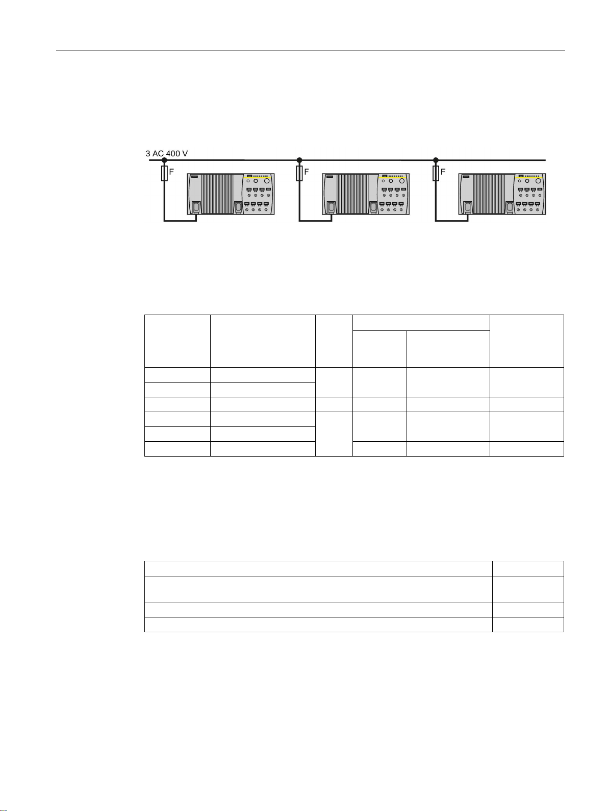
Feeder protection of individual inverters (Page 35)
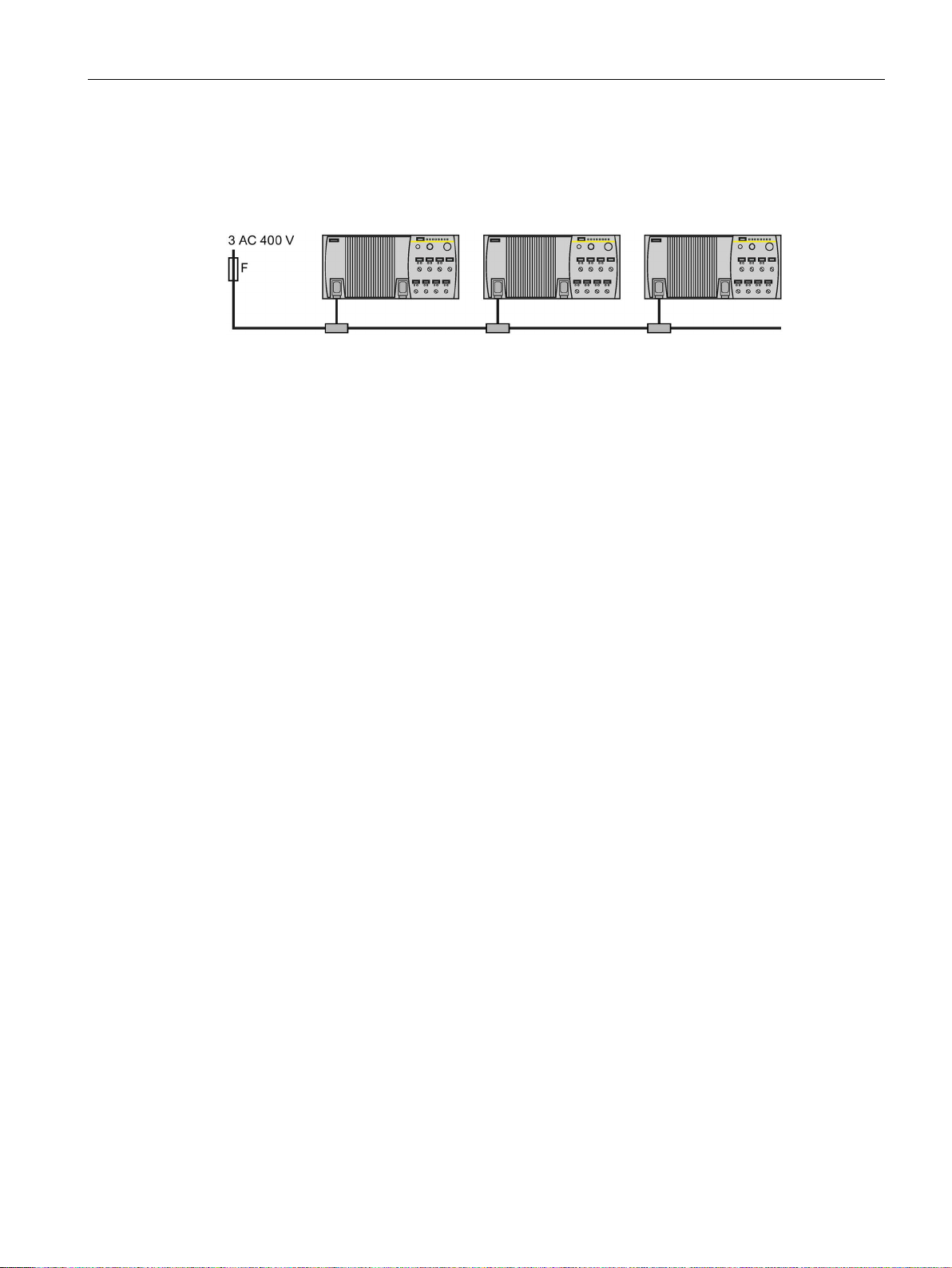
Feeder protection of multiple inverters
Converter with control units CU250D-2
Operating Instructions, 04/2015, FW V4.7.3, A5E34261542B AB
5
Page 6

Changes in this manual
Converter with control units CU250D-2
6 Operating Instructions, 04/2015, FW V4.7.3, A5E34261542B AB
Page 7

Table of contents
Changes in this manual ........................................................................................................................... 5
1 Fundamental safety instructions ............................................................................................................ 13
2 Introduction ........................................................................................................................................... 21
3 Description ............................................................................................................................................ 23
4 Installation ............................................................................................................................................ 29
5 Commissioning ..................................................................................................................................... 59
1.1 General safety instructions ..................................................................................................... 13
1.2 Safety instructions for electromagnetic fields (EMF) .............................................................. 17
1.3 Handling electrostatic sensitive devices (ESD) ...................................................................... 17
1.4 Industrial security .................................................................................................................... 18
1.5 Residual risks of power drive systems .................................................................................... 19
2.1 About the Manual .................................................................................................................... 21
2.2 Guide through this manual ...................................................................................................... 22
3.1 SINAMICS G120D CU250D-2 Inverter ................................................................................... 23
3.2 Commissioning tools ............................................................................................................... 25
3.3 Supported motor series........................................................................................................... 27
4.1 Mechanical Installation............................................................................................................ 29
4.1.1 Drill pattern SINAMICS G120D ............................................................................................... 30
4.2 Electrical Installation ............................................................................................................... 32
4.2.1 Permissible line supplies ........................................................................................................ 32
4.2.2 Basic EMC Rules .................................................................................................................... 33
4.2.3 Overview of the interfaces ...................................................................................................... 34
4.2.4 Feeder protection of individual inverters ................................................................................. 35
4.2.5 Feeder protection of multiple inverters ................................................................................... 37
4.2.6 24-V power supply with multiple inverters .............................................................................. 40
4.2.7 Connections and cables ......................................................................................................... 41
4.2.8 Star-delta motor connection .................................................................................................... 49
4.2.9 Connecting the motor holding brake ....................................................................................... 50
4.2.10 Factory settings of the inputs and outputs .............................................................................. 51
4.2.11 Default settings of inputs and outputs ..................................................................................... 52
4.2.12 Connecting the PROFINET interface ...................................................................................... 53
4.2.13 Encoders examples ................................................................................................................ 53
4.2.14 Grounding converter and motor .............................................................................................. 54
4.2.15 Connections and interference suppression ............................................................................ 55
4.2.16 Equipotential bonding ............................................................................................................. 56
5.1 Commissioning guidelines ...................................................................................................... 59
5.2 Preparing for commissioning .................................................................................................. 60
Converter with control units CU250D-2
Operating Instructions, 04/2015, FW V4.7.3, A5E34261542B AB
7
Page 8

Table of contents
6 Adapt fieldbus configuration .................................................................................................................. 87
7 Advanced commissioning..................................................................................................................... 113
5.2.1 Which motor fits the converter? ............................................................................................. 61
5.2.2 Introduction, V/f control, vector control .................................................................................. 62
5.2.3 Defining additional requirements for the application .............................................................. 63
5.2.4 Encoder assignment .............................................................................................................. 63
5.3 Basic commissioning with IOP ............................................................................................... 65
5.4 Basic commissioning with a PC ............................................................................................. 69
5.4.1 Creating a project ................................................................................................................... 70
5.4.2 Transfer inverters connected via USB into the project .......................................................... 70
5.4.3 Go online and start the configuration wizard ......................................................................... 73
5.4.4 Carry-out basic commissioning .............................................................................................. 74
5.4.5 Adapting the encoder data ..................................................................................................... 78
5.4.6 Identify motor data ................................................................................................................. 79
5.5 Restoring the factory setting .................................................................................................. 82
5.5.1 Restoring the factory setting .................................................................................................. 82
5.5.2 Resetting the safety functions to the factory setting .............................................................. 83
5.5.3 Restore the settings to the factory settings (without safety functions)................................... 84
6.1 Fieldbus versions of the Control Unit ..................................................................................... 87
6.2 PROFIdrive profile for PROFIBUS and PROFINET .............................................................. 88
6.2.1 Cyclic communication ............................................................................................................ 88
6.2.1.1 Positioner: Cyclic communication .......................................................................................... 88
6.2.1.2 Control and status word 1 ...................................................................................................... 91
6.2.1.3 Control and status word 2 ...................................................................................................... 93
6.2.1.4 Control and status word for the positioner ............................................................................. 94
6.2.1.5 Control and status word 1 for the positioner .......................................................................... 96
6.2.1.6 Control and status word 2 for the positioner .......................................................................... 98
6.2.1.7 Control word block selection ................................................................................................ 100
6.2.1.8 Control word MDI mode ....................................................................................................... 101
6.2.1.9 Status word messages ......................................................................................................... 102
6.2.1.10 Function block FB283 .......................................................................................................... 103
6.2.1.11 Extend telegrams and change signal interconnection ......................................................... 103
6.2.1.12 Slave-to-slave communication ............................................................................................. 104
6.2.2 Acyclically reading and writing inverter parameters ............................................................. 104
6.3 Communication via PROFINET ........................................................................................... 105
6.3.1 What do you need for communication via PROFINET? ...................................................... 106
6.3.2 Integrating converters into PROFINET ................................................................................ 106
6.3.3 Configuring communication to the control ........................................................................... 107
6.3.4 Installing GSDML ................................................................................................................. 108
6.3.5 Select telegram .................................................................................................................... 108
6.3.6 Activating diagnostics via the control ................................................................................... 109
6.4 Communication via PROFIBUS ........................................................................................... 110
6.4.1 What do you need for communication via PROFIBUS? ...................................................... 110
6.4.2 Integrating the inverter in PROFIBUS .................................................................................. 110
6.4.3 Configuring the communication using SIMATIC S7 control ................................................. 111
6.4.4 Setting the address .............................................................................................................. 111
6.4.5 Select telegram .................................................................................................................... 112
Converter with control units CU250D-2
8 Operating Instructions, 04/2015, FW V4.7.3, A5E34261542B AB
Page 9

Table of contents
7.1 Overview of the converter functions ..................................................................................... 113
7.2 Inverter control ...................................................................................................................... 115
7.2.1 Adapt inputs and outputs ...................................................................................................... 115
7.2.1.1 Digital inputs ......................................................................................................................... 116
7.2.1.2 Fail-safe digital input ............................................................................................................. 117
7.2.1.3 Digital outputs ....................................................................................................................... 119
7.2.2 Switching the motor on and off ............................................................................................. 120
7.2.3 Running the motor in jog mode (JOG function) .................................................................... 122
7.2.4 Switching over the inverter control (command data set) ...................................................... 124
7.3 Setpoints ............................................................................................................................... 126
7.3.1 Overview ............................................................................................................................... 126
7.3.2 Specifying the setpoint via the fieldbus................................................................................. 127
7.3.3 Motorized potentiometer as setpoint source ......................................................................... 128
7.3.4 Fixed speed as setpoint source ............................................................................................ 130
7.4 Setpoint calculation ............................................................................................................... 133
7.4.1 Overview of setpoint preparation .......................................................................................... 133
7.4.2 Invert setpoint ....................................................................................................................... 134
7.4.3 Inhibit direction of rotation ..................................................................................................... 135
7.4.4 Skip frequency bands and minimum speed .......................................................................... 136
7.4.5 Speed limitation .................................................................................................................... 137
7.4.6 Ramp-function generator ...................................................................................................... 138
7.5 Motor control ......................................................................................................................... 143
7.5.1 V/f control .............................................................................................................................. 143
7.5.1.1 Characteristics of U/f control ................................................................................................. 144
7.5.1.2 Selecting the U/f characteristic ............................................................................................. 145
7.5.1.3 Optimizing motor starting ...................................................................................................... 145
7.5.2 Vector control with speed controller ...................................................................................... 147
7.5.2.1 Checking the encoder signal ................................................................................................ 148
7.5.2.2 Select motor control .............................................................................................................. 149
7.5.2.3 Optimizing the speed controller ............................................................................................ 150
7.5.2.4 Advanced settings ................................................................................................................. 152
7.5.2.5 Friction characteristic ............................................................................................................ 153
7.5.2.6 Moment of inertia estimator .................................................................................................. 156
7.5.3 Operating the converter without position controller .............................................................. 161
7.6 Basic positioner and position control .................................................................................... 163
7.6.1 Basic positioner and position control ....................................................................................
163
7.6.2 Commissioning sequence ..................................................................................................... 164
7.6.3 Normalizing the encoder signal ............................................................................................ 165
7.6.3.1 Define the resolution ............................................................................................................. 165
7.6.3.2 Modulo range setting ............................................................................................................ 167
7.6.3.3 Checking the actual position value ....................................................................................... 169
7.6.3.4 Setting the backlash.............................................................................................................. 170
7.6.4 Limiting the positioning range ............................................................................................... 172
7.6.5 Setting the position controller ............................................................................................... 174
7.6.5.1 Precontrol and gain ............................................................................................................... 174
7.6.5.2 Optimizing the position controller .......................................................................................... 175
7.6.5.3 Limiting the traversing profile ................................................................................................ 178
7.6.6 Setting the monitoring functions ........................................................................................... 180
7.6.6.1 Standstill and positioning monitoring .................................................................................... 180
7.6.6.2 Following error monitoring .................................................................................................... 182
Converter with control units CU250D-2
Operating Instructions, 04/2015, FW V4.7.3, A5E34261542B AB
9
Page 10

Table of contents
8 Backing up data and series commissioning .......................................................................................... 275
7.6.6.3 Cam sequencer .................................................................................................................... 184
7.6.7 Referencing .......................................................................................................................... 185
7.6.7.1 Referencing methods ........................................................................................................... 185
7.6.7.2 Setting the reference point approach ................................................................................... 187
7.6.7.3 Setting the flying referencing ............................................................................................... 193
7.6.7.4 Set reference point ............................................................................................................... 198
7.6.7.5 Absolute encoder adjustment .............................................................................................. 200
7.6.8 Jogging ................................................................................................................................. 202
7.6.8.1 Jog velocity .......................................................................................................................... 202
7.6.8.2 Incremental jogging .............................................................................................................. 203
7.6.8.3 Setting jogging ..................................................................................................................... 203
7.6.9 Traversing blocks ................................................................................................................. 205
7.6.9.1 Travel to fixed stop ............................................................................................................... 213
7.6.9.2 Examples ............................................................................................................................. 218
7.6.10 Direct setpoint input (MDI) ................................................................................................... 220
7.7 Protection functions ............................................................................................................. 226
7.7.1 Inverter temperature monitoring ........................................................................................... 226
7.7.2 Motor temperature monitoring using a temperature sensor ................................................ 229
7.7.3 Protecting the motor by calculating the motor temperature ................................................. 232
7.7.4 Overcurrent protection ......................................................................................................... 234
7.8 Application-specific functions ............................................................................................... 235
7.8.1 Functions that match the application ................................................................................... 235
7.8.2 Unit changeover ................................................................................................................... 236
7.8.2.1 Changing over the motor standard ...................................................................................... 237
7.8.2.2 Changing over the unit system ............................................................................................ 238
7.8.2.3 Switching units with STARTER ............................................................................................ 238
7.8.3 Electrically braking the motor ............................................................................................... 240
7.8.3.1 DC braking ........................................................................................................................... 240
7.8.3.2 Braking with regenerative feedback to the line .................................................................... 243
7.8.4 Motor holding brake ............................................................................................................. 244
7.8.5 System protection ................................................................................................................ 248
7.8.5.1 No-load monitoring, blocking protection, stall protection ..................................................... 249
7.8.5.2 Load monitoring ................................................................................................................... 250
7.9 Safe Torque Off (STO) safety function ................................................................................ 255
7.9.1 Function description ............................................................................................................. 255
7.9.2 Prerequisite for STO use ................................................................
..................................... 257
7.9.3 Commissioning STO ............................................................................................................ 257
7.9.3.1 Commissioning tools ............................................................................................................ 257
7.9.3.2 Protection of the settings from unauthorized changes......................................................... 258
7.9.3.3 Configuring safety functions ................................................................................................. 258
7.9.3.4 Interconnecting the "STO active" signal............................................................................... 259
7.9.3.5 Setting the filter for safety-related inputs ............................................................................. 260
7.9.3.6 Setting the forced checking procedure (test stop) ............................................................... 263
7.9.3.7 Activate settings and check digital inputs ............................................................................ 264
7.9.3.8 Acceptance - completion of commissioning ......................................................................... 268
7.10 Switchover between different settings ................................................................................. 272
8.1 Saving settings on a memory card....................................................................................... 276
8.1.1 Saving settings to the memory card..................................................................................... 277
Converter with control units CU250D-2
10 Operating Instructions, 04/2015, FW V4.7.3, A5E34261542B AB
Page 11

Table of contents
9 Corrective maintenance ...................................................................................................................... 295
10 Alarms, faults and system messages .................................................................................................. 319
11 Technical data .................................................................................................................................... 345
8.1.2 Transferring the settings from the memory card ................................................................... 278
8.1.3 Safely remove the memory card ........................................................................................... 278
8.2 Backing up and transferring settings using STARTER ......................................................... 281
8.3 Saving settings and transferring them using an operator panel ........................................... 285
8.4 Other ways to back up settings ............................................................................................. 286
8.5 Write and know-how protection ............................................................................................ 287
8.5.1 Write protection ..................................................................................................................... 287
8.5.2 Know-how protection ............................................................................................................ 289
8.5.2.1 Settings for know-how protection .......................................................................................... 291
8.5.2.2 Generating an exception list for know-how protection .......................................................... 293
9.1 Replacing inverter components ............................................................................................ 295
9.1.1 Spare parts - external fan ..................................................................................................... 295
9.1.2 Overview of replacing converter components ...................................................................... 296
9.1.3 Replacing a Control Unit with enabled safety function ......................................................... 297
9.1.4 Replacing the Control Unit without the safety functions enabled ......................................... 301
9.1.5 Replacing the Control Unit without data backup ................................................................... 304
9.1.6 Replacing a Control Unit with active know-how protection ................................................... 305
9.1.7 Replacing a Power Module with enabled safety function ..................................................... 307
9.1.8 Replacing a Power Module without the safety function being enabled ................................ 308
9.2 Firmware upgrade and downgrade ....................................................................................... 309
9.2.1 Upgrading firmware ............................................................................................................... 310
9.2.2 Firmware downgrade ............................................................................................................ 312
9.2.3 Correcting a failed firmware upgrade or downgrade ............................................................ 314
9.3 Reduced acceptance after component replacement and firmware change ......................... 315
9.4 If the converter no longer responds ...................................................................................... 316
10.1 Alarms ................................................................................................................................... 319
10.2 Faults .................................................................................................................................... 323
10.3 Status LED overview............................................................................................................. 328
10.4 Identification & maintenance data (I&M) ............................................................................... 330
10.5 System runtime ..................................................................................................................... 331
10.6 List of alarms and faults ........................................................................................................ 332
11.1 Performance ratings Control Unit ......................................................................................... 345
11.2 Performance ratings Power Module ..................................................................................... 347
11.3 SINAMICS G120D specifications ......................................................................................... 348
11.4 Data regarding the power loss in partial load operation ....................................................... 349
11.5 Ambient operating conditions ............................................................................................... 349
11.6 Current derating - depending on the installation altitude ...................................................... 350
Converter with control units CU250D-2
Operating Instructions, 04/2015, FW V4.7.3, A5E34261542B AB
11
Page 12

Table of contents
A Appendix ............................................................................................................................................. 357
Index ................................................................................................................................................... 391
11.7 Pulse frequency and current reduction ................................................................................ 351
11.8 Standards (PM250D) ........................................................................................................... 352
11.9 Electromagnetic Compatibility .............................................................................................. 353
A.1 New and extended functions ................................................................................................ 357
A.2 Parameter ............................................................................................................................ 362
A.3 The device trace in STARTER ............................................................................................. 365
A.4 Interconnecting signals in the inverter ................................................................................. 368
A.4.1 Fundamentals ...................................................................................................................... 368
A.4.2 Example ............................................................................................................................... 370
A.5 Application Examples ........................................................................................................... 372
A.5.1 Setting an absolute encoder ................................................................................................ 372
A.5.2 Connecting the safety-related input ..................................................................................... 376
A.5.3 Connecting fail-safe digital inputs ........................................................................................ 376
A.6 Setting a non standard HTL encoder ................................................................................... 377
A.7 Setting a non standard SSI encoder .................................................................................... 378
A.8 Acceptance tests for the safety functions ............................................................................ 381
A.8.1 Recommended acceptance test .......................................................................................... 381
A.8.2 Machine documentation ....................................................................................................... 384
A.8.3 Log of the settings for the basic functions, firmware V4.4 ... V4.7 SP2 ............................... 386
A.9 Manuals and technical support ............................................................................................ 387
A.9.1 Manuals for your inverter ..................................................................................................... 387
A.9.2 Configuring support .............................................................................................................. 388
A.9.3 Product Support ................................................................................................................... 388
A.10 Mistakes and improvements ................................................................................................ 389
Converter with control units CU250D-2
12 Operating Instructions, 04/2015, FW V4.7.3, A5E34261542B AB
Page 13
1
1.1
General safety instructions
DANGER
Danger to life due to live parts and other energy sources
WARNING
Danger to life through a hazardous voltage when connecting an unsuitable power supply
Death or serious injury can result when live parts are touched.
• Only work on electrical devices when you are qualified for this job.
• Always observe the country-specific safety rules.
Generally, six steps apply when establishing safety:
1. Prepare for shutdown and notify all those who will be affected by the procedure.
2. Disconnect the machine from the supply.
– Switch off the machine.
– Wait until the discharge time specified on the warning labels has elapsed.
– Check that it really is in a no-voltage condition, from phase conductor to phase
conductor and phase conductor to protective conductor.
– Check whether the existing auxiliary supply circuits are de-energized.
– Ensure that the motors cannot move.
3. Identify all other dangerous energy sources, e.g. compressed air, hydraulic systems, or
water.
4. Isolate or neutralize all hazardous energy sources by closing switches, grounding or
short-circuiting or closing valves, for example.
5. Secure the energy sources against switching on again.
6. Ensure that the correct machine is completely interlocked.
After you have completed the work, restore the operational readiness in the inverse
sequence.
Touching live components can result in death or severe injury.
• Only use power supplies that provide SELV (Safety Extra Low Voltage) or PELV-
(Protective Extra Low Voltage) output voltages for all connections and terminals of the
electronics modules.
Converter with control units CU250D-2
Operating Instructions, 04/2015, FW V4.7.3, A5E34261542B AB
13
Page 14
Fundamental safety instructions
WARNING
Danger to life when live parts are touched on damaged devices
WARNING
Danger to life through electric shock due to unconnected cable shields
WARNING
Danger to life due to electric shock when not grounded
WARNING
Danger to life due to electric shock when opening plug connections in operation
WARNING
Danger to life due to fire spreading if housing is inadequate
1.1 General safety instructions
Improper handling of devices can cause damage.
For damaged devices, hazardous voltages can be present at the enclosure or at exposed
components; if touched, this can result in death or severe injury.
• Ensure compliance with the limit values specified in the technical data during transport,
storage and operation.
• Do not use any damaged devices.
Hazardous touch voltages can occur through capacitive cross-coupling due to unconnected
cable shields.
• As a minimum, connect cable shields and the conductors of power cables that are not
used (e.g. brake cores) at one end at the grounded housing potential.
For missing or incorrectly implemented protective conductor connection for devices with
protection class I, high voltages can be present at open, exposed parts, which when
touched, can result in death or severe injury.
• Ground the device in compliance with the applicable regulations.
When opening plug connections in operation, arcs can result in severe injury or death.
• Only open plug connections when the equipment is in a no-voltage state, unless it has
been explicitly stated that they can be opened in operation.
Fire and smoke development can cause severe personal injury or material damage.
• Install devices without a protective housing in a metal control cabinet (or protect the
device by another equivalent measure) in such a way that contact with fire is prevented.
• Ensure that smoke can only escape via controlled and monitored paths.
Converter with control units CU250D-2
14 Operating Instructions, 04/2015, FW V4.7.3, A5E34261542B AB
Page 15

Fundamental safety instructions
WARNING
Danger to life through unexpected movement of machines when using mobile wireless
devices or mobile phones
WARNING
Danger to life due to the motor catching fire in the event of insulation overload
WARNING
Danger to life due to fire if overheating occurs because of insufficient ventilation clearances
WARNING
Danger of an accident occurring due to missing or illegible warning labels
1.1 General safety instructions
Using mobile wireless devices or mobile phones with a transmit power > 1 W closer than
approx. 2 m to the components may cause the devices to malfunction, influence the
functional safety of machines therefore putting people at risk or causing material damage.
• Switch the wireless devices or mobile phones off in the immediate vicinity of the
components.
There is higher stress on the motor insulation through a ground fault in an IT system. If the
insulation fails, it is possible that death or severe injury can occur as a result of smoke and
fire.
• Use a monitoring device that signals an insulation fault.
• Correct the fault as quickly as possible so the motor insulation is not overloaded.
Inadequate ventilation clearances can cause overheating of components with subsequent
fire and smoke. This can cause severe injury or even death. This can also result in
increased downtime and reduced service lives for devices/systems.
• Ensure compliance with the specified minimum clearance as ventilation clearance for
the respective component.
Missing or illegible warning labels can result in accidents involving death or serious injury.
• Check that the warning labels are complete based on the documentation.
• Attach any missing warning labels to the components, in the national language if
necessary.
• Replace illegible warning labels.
Converter with control units CU250D-2
Operating Instructions, 04/2015, FW V4.7.3, A5E34261542B AB
15
Page 16

Fundamental safety instructions
NOTICE
Device damage caused by incorrect voltage/insulation tests
WARNING
Danger to life when safety functions are inactive
Note
Important safety notices for Safety Integrated functions
If you want to use Safety Integrated functions, you must observe the safety notices in the
Safety Integrated manuals.
WARNING
Danger to life or malfunctions of the machine as a result of incorrect or changed
parameterization
1.1 General safety instructions
Incorrect voltage/insulation tests can damage the device.
• Before carrying out a voltage/insulation check of the system/machine, disconnect the
devices as all converters and motors have been subject to a high voltage test by the
manufacturer, and therefore it is not necessary to perform an additional test within the
system/machine.
Safety functions that are inactive or that have not been adjusted accordingly can cause
operational faults on machines that could lead to serious injury or death.
• Observe the information in the appropriate product documentation before
commissioning.
• Carry out a safety inspection for functions relevant to safety on the entire system,
including all safety-related components.
• Ensure that the safety functions used in your drives and automation tasks are adjusted
and activated through appropriate parameterizing.
• Perform a function test.
• Only put your plant into live operation once you have guaranteed that the functions
relevant to safety are running correctly.
As a result of incorrect or changed parameterization, machines can malfunction, which in
turn can lead to injuries or death.
• Protect the parameterization (parameter assignments) against unauthorized access.
• Respond to possible malfunctions by applying suitable measures (e.g. EMERGENCY
STOP or EMERGENCY OFF).
Converter with control units CU250D-2
16 Operating Instructions, 04/2015, FW V4.7.3, A5E34261542B AB
Page 17

Fundamental safety instructions
1.2
Safety instructions for electromagnetic fields (EMF)
WARNING
Danger to life from electromagnetic fields
1.3
Handling electrostatic sensitive devices (ESD)
NOTICE
Damage through electric fields or electrostatic discharge
1.2 Safety instructions for electromagnetic fields (EMF)
Electromagnetic fields (EMF) are generated by the operation of electrical power equipment
such as transformers, converters or motors.
People with pacemakers or implants are at a special risk in the immediate vicinity of these
devices/systems.
• Ensure that the persons involved are the necessary distance away (minimum 2 m).
Electrostatic sensitive devices (ESD) are individual components, integrated circuits, modules
or devices that may be damaged by either electric fields or electrostatic discharge.
Electric fields or electrostatic discharge can cause malfunctions through damaged
individual components, integrated circuits, modules or devices.
• Only pack, store, transport and send electronic components, modules or devices in their
original packaging or in other suitable materials, e.g conductive foam rubber of
aluminum foil.
• Only touch components, modules and devices when you are grounded by one of the
following methods:
– Wearing an ESD wrist strap
– Wearing ESD shoes or ESD grounding straps in ESD areas with conductive flooring
• Only place electronic components, modules or devices on conductive surfaces (table
with ESD surface, conductive ESD foam, ESD packaging, ESD transport container).
Converter with control units CU250D-2
Operating Instructions, 04/2015, FW V4.7.3, A5E34261542B AB
17
Page 18

Fundamental safety instructions
1.4
Industrial security
Note
Industrial security
Siemens provides products and solutions with industrial security functions that support the
secure operation o
important components in a holistic industrial security concept. With this in mind, Siemens’
products and solutions undergo continuous development. Siemens recommends strongly
that you regul
For the secure operation of Siemens products and solutions, it is necessary to take suitable
preventive action (e.g. cell protection concept) and integrate each component into a holistic,
state
also be considered. For more information about industrial security, visit this address
(
To st
newsletter. For more information, visit this address (
).
WARNING
Danger as a result of unsafe operating states resulting from software manipulation
1.4 Industrial security
f plants, solutions, machines, equipment and/or networks. They are
arly check for product updates.
-of-the-art industrial security concept. Third-party products that may be in use should
http://www.siemens.com/industrialsecurity).
ay informed about product updates as they occur, sign up for a product-specific
http://support.automation.siemens.com
Software manipulation (e.g. by viruses, Trojan horses, malware, worms) can cause unsafe
operating states to develop in your installation which can result in death, severe injuries
and/or material damage.
• Keep the software up to date.
You will find relevant information and newsletters at this address
(http://support.automation.siemens.com).
• Incorporate the automation and drive components into a holistic, state-of-the-art
industrial security concept for the installation or machine.
You will find further information at this address
(http://www.siemens.com/industrialsecurity).
• Make sure that you include all installed products into the holistic industrial security
concept.
Converter with control units CU250D-2
18 Operating Instructions, 04/2015, FW V4.7.3, A5E34261542B AB
Page 19

Fundamental safety instructions
1.5
Residual risks of power drive systems
1.5 Residual risks of power drive systems
The control and drive components of a drive system are approved for industrial and
commercial use in industrial line supplies. Their use in public line supplies requires a
different configuration and/or additional measures.
These components may only be operated in closed housings or in higher-level control
cabinets with protective covers that are closed, and when all of the protective devices are
used.
These components may only be handled by qualified and trained technical personnel who
are knowledgeable and observe all of the safety instructions on the components and in the
associated technical user documentation.
When assessing the machine's risk in accordance with the respective local regulations (e.g.,
EC Machinery Directive), the machine manufacturer must take into account the following
residual risks emanating from the control and drive components of a drive system:
1. Unintentional movements of driven machine components during commissioning,
operation, maintenance, and repairs caused by, for example,
– Hardware and/or software errors in the sensors, control system, actuators, and cables
and connections
– Response times of the control system and of the drive
– Operation and/or environmental conditions outside the specification
– Condensation/conductive contamination
– Parameterization, programming, cabling, and installation errors
– Use of wireless devices/mobile phones in the immediate vicinity of the control system
– External influences/damage
2. In the event of a fault, exceptionally high temperatures, including an open fire, as well as
emissions of light, noise, particles, gases, etc. can occur inside and outside the inverter,
e.g.:
– Component failure
– Software errors
– Operation and/or environmental conditions outside the specification
– External influences/damage
Inverters of the Open Type/IP20 degree of protection must be installed in a metal control
cabinet (or protected by another equivalent measure) such that contact with fire inside
and outside the inverter is not possible.
Converter with control units CU250D-2
Operating Instructions, 04/2015, FW V4.7.3, A5E34261542B AB
19
Page 20

Fundamental safety instructions
Note
The components must be protected against conductive contamination (e.g. by installing them
in a control cabinet with degree of protection IP54 according to IEC 60529 or NEMA 12).
Assuming that conductive contamin
lower degree of cabinet protection may be permitted.
1.5 Residual risks of power drive systems
3. Hazardous shock voltages caused by, for example,
– Component failure
– Influence during electrostatic charging
– Induction of voltages in moving motors
– Operation and/or environmental conditions outside the specification
– Condensation/conductive contamination
– External influences/damage
4. Electrical, magnetic and electromagnetic fields generated in operation that can pose a
risk to people with a pacemaker, implants or metal replacement joints, etc., if they are too
close
5. Release of environmental pollutants or emissions as a result of improper operation of the
system and/or failure to dispose of components safely and correctly
ation at the installation site can definitely be excluded, a
For more information about residual risks of the components in a drive system, see the
relevant sections in the technical user documentation.
Converter with control units CU250D-2
20 Operating Instructions, 04/2015, FW V4.7.3, A5E34261542B AB
Page 21

2
2.1
About the Manual
Who requires the operating instructions and what for?
What is described in the operating instructions?
What is the meaning of the symbols in the manual?
These operating instructions primarily address fitters, commissioning engineers and machine
operators. The operating instructions describe the devices and device components and
enable the target groups being addressed to install, connect-up, set, and commission the
converters safely and in the correct manner.
These operating instructions provide a summary of all of the information required to operate
the converter under normal, safe conditions.
The information provided in the operating instructions has been compiled in such a way that
it is sufficient for all standard applications and enables drives to be commissioned as
efficiently as possible. Where it appears useful, additional information for entry level
personnel has been added.
The operating instructions also contain information about special applications. Since it is
assumed that readers already have a sound technical knowledge of how to configure and
parameterize these applications, the relevant information is summarized accordingly. This
relates, e.g. to operation with fieldbus systems and safety-related applications.
An operating instruction starts here.
This concludes the operating instruction.
The subsequent text is applicable for an operator panel.
The following text applies if you are using a PC with STARTER.
Symbol for inverter functions.
See also: Overview of the converter functions (Page 113).
Converter with control units CU250D-2
Operating Instructions, 04/2015, FW V4.7.3, A5E34261542B AB
21
Page 22
Introduction
2.2
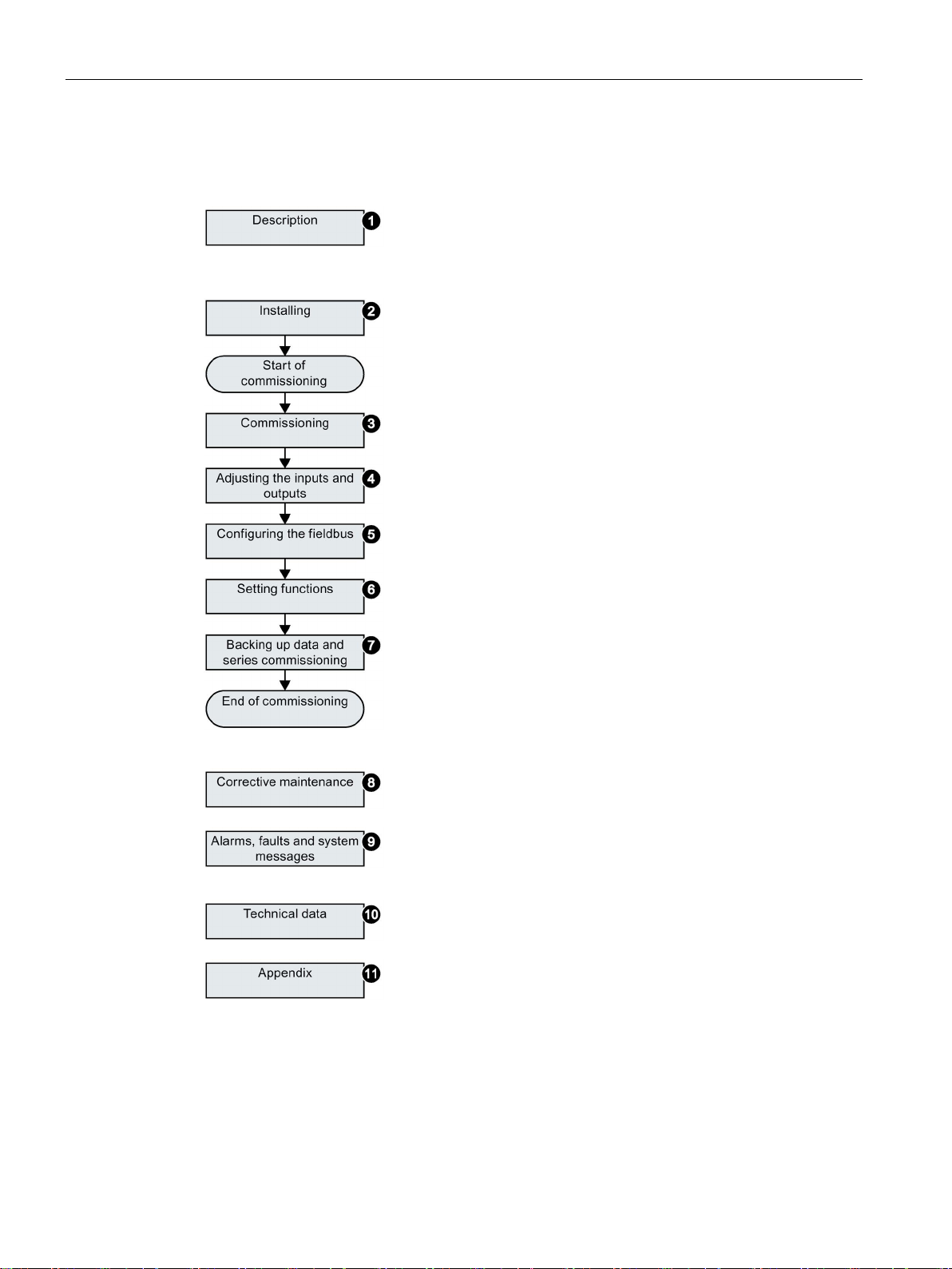
Guide through this manual
①
Inverter components and accessories.
Permissible motors.
Tools for commissioning.
②
Install and wire the inverter and its components.
Install the inverter in accordance with EMC.
③
Prepare for commissioning.
Restore the inverter to factory settings.
Define the inverter’s basic settings.
④
Adjust the fu
⑤
Configure communication via PROFIBUS or PROFINET.
Communication using other fieldbuses can be found in the
"Fieldbus" function manual; see also:
support (Page 387).
⑥
Set up the functions, e.g. setpoint processing, motor control
and protection functions.
⑦
Backup the inverter’s settings to an external data storage
medium, e.g. a memory
⑧
Replace the inverter and its components.
Firmware update.
⑨
Meaning of the LEDs on the front of the inverter.
System runtime.
Faults and warnings.
⑩
The most important technical data of the inverte
⑪
Setting up the new inverter functions.
Application examples.
2.2 Guide through this manual
nction of the inputs and outputs.
Manuals and technical
card or an operator panel.
Converter with control units CU250D-2
22 Operating Instructions, 04/2015, FW V4.7.3, A5E34261542B AB
r.
Page 23
3
Use for the intended purpose
3.1
SINAMICS G120D CU250D-2 Inverter
Overview
Designation
Interface
Encoder type
Order number
SSI Absolute Encoder
Push-Pull connections
The inverter described in this manual is a device for controlling an induction motor. The
inverter is designed for installation in electrical installations or machines.
It has been approved for industrial and commercial use on industrial networks. Additional
measures have to be taken when connected to public grids.
The technical specifications and information about connection conditions are indicated on
the rating plate and in the operating instructions.
The SINAMICS G120D is a converter for controlling the position of a drive. The converter
consists of two parts, the Control Unit (CU) and the Power Module (PM).
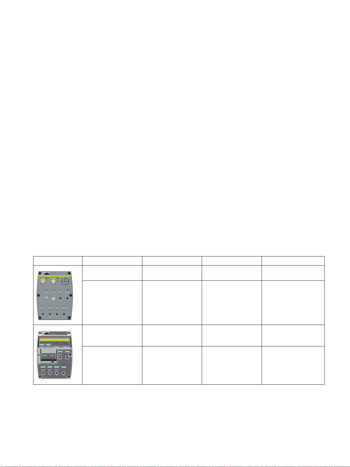
Table 3- 1 CU250D-2 Control Units
CU250D-2 DP-F PROFIBUS HTL Encoder
CU250D-2 PN-F PROFINET, Ether-
CU250D-2 PN-F PP PROFINET, Ether-
CU250D-2 PN-F FO PROFINET, Ether-
Net/IP
Net/IP
Net/IP
Fibre optic connections
HTL Encoder
SSI Absolute Encoder
HTL Encoder
SSI Absolute Encoder
HTL Encoder
SSI Absolute Encoder
6SL3546-0FB21-1PA0
6SL3546-0FB21-1FA0
6SL3546-0FB21-1FB0
6SL3546-0FB21-1FC0
Converter with control units CU250D-2
Operating Instructions, 04/2015, FW V4.7.3, A5E34261542B AB
23
Page 24
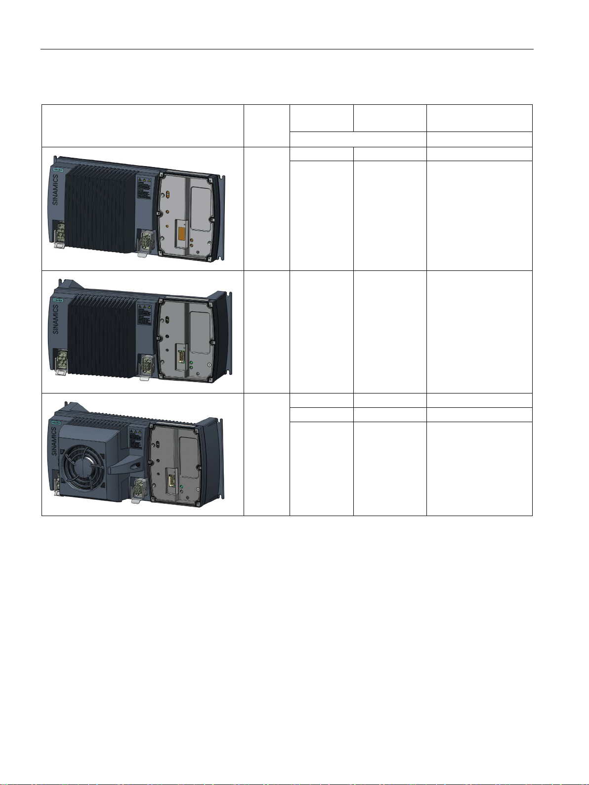
Description
Frame
size
Rated output
power
Rated output
current
Order number
based on High Overload (HO)
0.75 kW
2.2 A
6SL3525-0PE17-5AA1
4.0 kW
10.2 A
6SL3525-0PE24-0AA1
5.5 kW
13.2 A
6SL3525-0PE25-5AA1
3.1 SINAMICS G120D CU250D-2 Inverter
Table 3- 2 PM250D Power Modules
FSA
1.5 kW 4.1 A 6SL3525-0PE21-5AA1
FSB 3.0 kW 7.7 A 6SL3525-0PE23-0AA1
FSC
7.5 kW 19.0 A 6SL3525-0PE27-5AA1
Converter with control units CU250D-2
24 Operating Instructions, 04/2015, FW V4.7.3, A5E34261542B AB
Page 25
Description
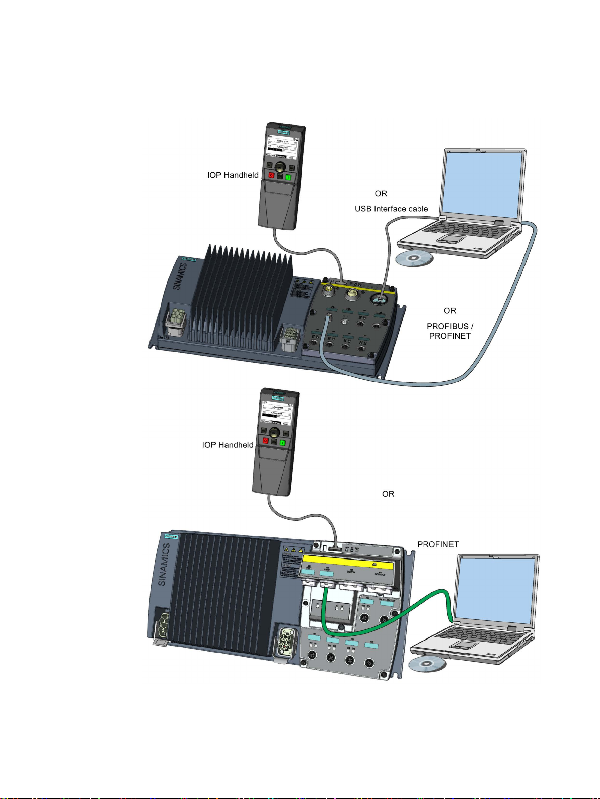
3.2
Commissioning tools
3.2 Commissioning tools
Figure 3-1 Commissioning tools - PC or IOP Handheld Kit
Converter with control units CU250D-2
Operating Instructions, 04/2015, FW V4.7.3, A5E34261542B AB
25
Page 26

Description
Component or tool
Order number
Operator Panel
IOP Handheld
6SL3255-0AA00-4HA0
W/view/en/26233208)
W/view/en/68034568)
PC Connection Kit
Comprising USB cable (3 m).
6SL3255-0AA00-2CA0
Memory cards
Scope of delivery
Article number
Memory card without firmware
6SL3054-4AG00-2AA0
Memory card with firmware V4.6
6SL3054-7EG00-2BA0
Memory card with firmware V4.7
6SL3054-7EH00-2BA0
Memory card with firmware V4.7 SP3
6SL3054-7TB00-2BA0
3.2 Commissioning tools
Table 3- 3 Components and tools for commissioning
STARTER Commissioning tool (PC soft-
ware)
Startdrive You obtain Startdrive on a DVD (Article
Table 3- 4 Memory cards to back up inverter settings
You obtain STARTER on a DVD (Article
number: 6SL3072-0AA00-0AG0)
and it can be downloaded:
Download STARTER
(http://support.automation.siemens.com/W
number: 6SL3072-4CA02-1XG0)
and it can be downloaded:
Startdrive
(http://support.automation.siemens.com/W
Converter with control units CU250D-2
26 Operating Instructions, 04/2015, FW V4.7.3, A5E34261542B AB
Page 27
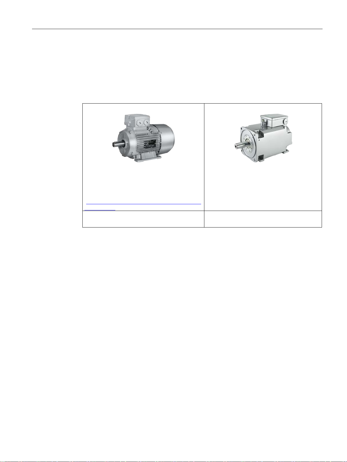
Description
3.3
Supported motor series
Supported motors
SIMOTICS GP, SIMOTICS SD IEC motors
en/84049346).
SIMOTICS M main motors
Motors from other manufacturers
Standard induction motors
3.3 Supported motor series
Table 3- 5 Motor series suitable for the inverter
1LG6, 1LA7, 1LA9 and 1LE1 standard induction
motors
Multi-motor drive is permissible, i.e. multiple motors operated on one inverter. See also: Multimotor drive
(http://support.automation.siemens.com/WW/view/
1PH8 induction motors
Converter with control units CU250D-2
Operating Instructions, 04/2015, FW V4.7.3, A5E34261542B AB
27
Page 28

Description
3.3 Supported motor series
Converter with control units CU250D-2
28 Operating Instructions, 04/2015, FW V4.7.3, A5E34261542B AB
Page 29
4
4.1
Mechanical Installation
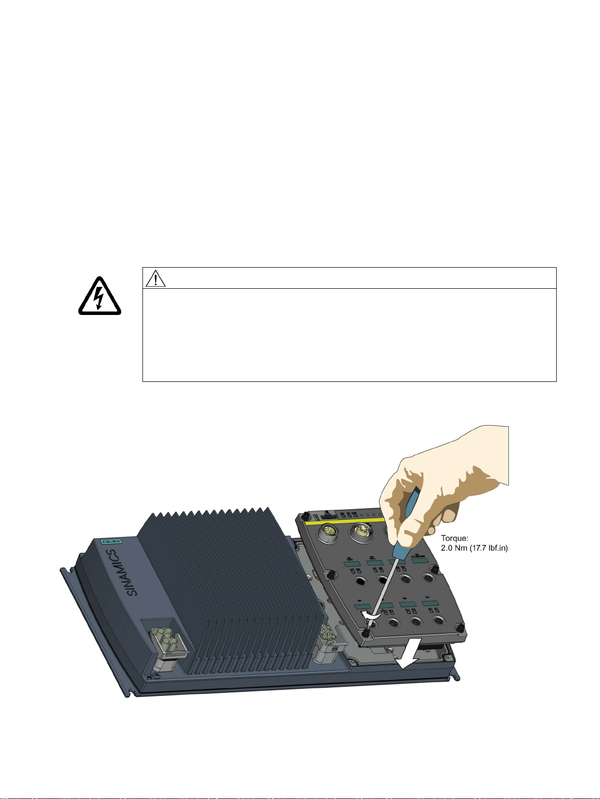
Fitting the Control Unit to the Power Module
CAUTION
Seals fitted correctly
TN and TT mains supplies
The inverter is delivered as two separate components - the Power Module (PM) and the
Control Unit (CU). The CU must be fitted to the PM prior to any further commissioning taking
place.
It is important that when assembling the Power Module and the Control Unit that all the
seals are fitted correctly to ensure IP65 rating.
The SINAMICS PM250D Power Module with the Class A integrated mains filter is only
suitable for operation on TN and TT mains supplies.
The CU is fitted to the PM as shown in the diagram below.
Figure 4-1 Fitting the Control Unit to the Power Module
Converter with control units CU250D-2
Operating Instructions, 04/2015, FW V4.7.3, A5E34261542B AB
29
Page 30
Installation
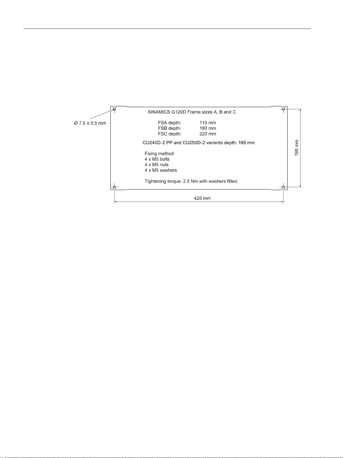
4.1.1
Drill pattern SINAMICS G120D
Drill pattern and dimensions
4.1 Mechanical Installation
The inverter has an identical drill pattern for all frame sizes. The drill pattern, depth and
tightening torques are shown in the diagram below.
Figure 4-2 SINAMICS G120D drill pattern
Converter with control units CU250D-2
30 Operating Instructions, 04/2015, FW V4.7.3, A5E34261542B AB
Page 31
Installation
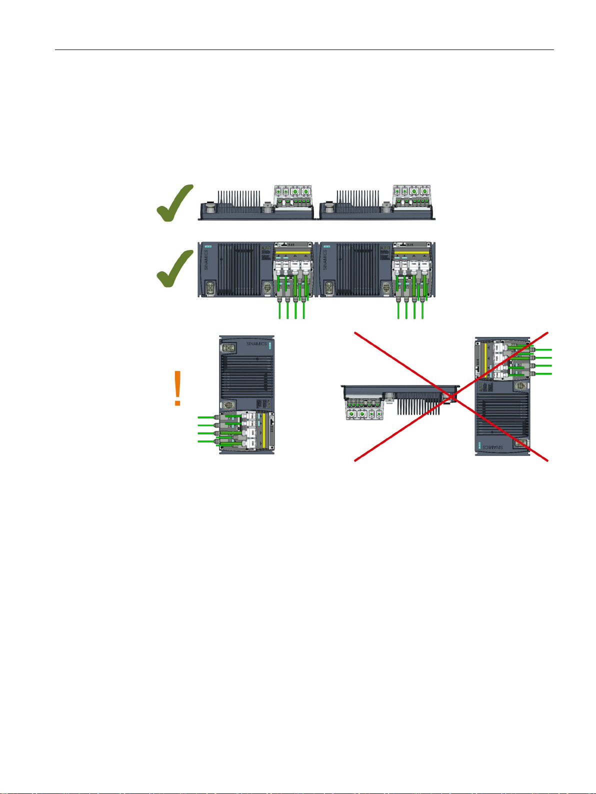
Mounting orientation
Restrictions due to vertical mounting
4.1 Mechanical Installation
Mount the converter on a table or on a wall. The minimum clearance distances are as
follows:
● Side-by-side - no clearance distance is required
● Above and below the inverter 150 mm (5.9 inches).
Figure 4-3 Mounting orientation: correct (✓), impermissible (X), permissible with restrictions (!)
If the converter is mounted in the vertical position, the maximum ambient temperature is
40°C.
Additionally you have to reduce the converter output current to 80 % of rated converter
current.
If the output current derating adversely affects the application, you have to use an converter
of the next highest power rating.
Converter with control units CU250D-2
Operating Instructions, 04/2015, FW V4.7.3, A5E34261542B AB
31
Page 32

Installation
4.2
Electrical Installation
NOTICE
Material damage from inappropriate supply system Vt > 1%
4.2.1
Permissible line supplies
Operation on an IT line system is not permitted.
Operation on TN and TT line systems
TN line system
TT system
Prohibited operation
4.2 Electrical Installation
Operating the converter on an inappropriate supply system can cause damage to the
converter and other loads.
• Only operate the converter on supply systems with V
≤ 1%.
t
In an IT line system, all of the conductors are insulated with respect to the PE protective
conductor – or connected to the PE protective conductor through an impedance.
Operation on IT line systems is not permitted.
The TN line system in accordance with IEC 60364-1 (2005) transmits the PE conductor to
the installation via a conductor.
Generally, in a TN line system the neutral point is grounded. There are versions of a TN line
supply with a grounded line the conductor, e.g. with grounded L1.
A TN line system can transfer the neutral conductor N and the PE protective conductor either
separately or combined.
In a TT line system, the transformer grounding and the installation grounding are
independent of one another.
There are TT line supplies where the neutral conductor N is either transferred – or not.
Operation of the inverter on the TN and TT line system
The inverter is designed for TN and TT line systems with a grounded neutral point
Above an installation altitude of 2000 m, the permissible line supplies are restricted. See
also: Current derating - depending on the installation altitude (Page 350).
● Operation on TN line systems with grounded external conductors is prohibited.
● Operation on TT line systems without grounded neutral points is prohibited.
Converter with control units CU250D-2
32 Operating Instructions, 04/2015, FW V4.7.3, A5E34261542B AB
Page 33

Installation
4.2.2
Basic EMC Rules
Measures to limit Electromagnetic Interference (EMI)
Cables
Cable shields
4.2 Electrical Installation
Listed below are the necessary measures that must be taken to ensure the correct
installation of the Inverter within a system, which will minimize the effect of EMI.
● Keep all cable lengths to the minimum possible length; avoid excessive cable lengths.
● Route always signal and data cables, as well as their associated equipotential bonding
cables, in parallel and with as short a distance as possible.
● Don't route signal and data cables and line supply cables in parallel to motor cables.
● Signal and data cables and line supply cables should not cross motor cables; if crossing
is necessary, they should cross at an angle of 90 °.
● Shield signal and data cables.
● Route particularly sensitive signal cables, such as setpoint and actual value cables, with
optimum shield bonding at both ends and without any interruptions of the shield.
● Ground spare wires for signal and data cables at both ends.
● Route all power cables (line supply cables, as well as motor cables) separately from
signal and data cables. The minimum distance should be approximately 25 cm.
Exception: hybrid motor cables with integrated shielded temperature sensor and brake
control wires are allowed.
● Shield the power cable between inverter and motor. We recommend shielded cables with
symmetrical three-phase conductors (L1, L2, and L3) and an integrated, 3-wire, and
symmetrically arranged PE conductor.
● Use shielded cables with finely stranded braided shields. Foil shields are not suitable
since they are much less effective.
● Connect shields to the grounded housings at both ends with excellent electrical
conductivity and a large contact area.
● Bond the cable shields to the plug connectors of the inverter.
● Don't interrupt cable shields by intermediate terminals.
● In the case of both, the power cables and the signal and data cables, the cable shields
should be connected by means of suitable EMC shield clips or via electrically conductive
PG glands. These must connect the shields to the shield bonding options for cables and
the unit housing respectively with excellent electrical conductivity and a large contact
area.
● Use only metallic or metallized connector housings for shielded data cables (e. g.
PROFIBUS cables).
Converter with control units CU250D-2
Operating Instructions, 04/2015, FW V4.7.3, A5E34261542B AB
33
Page 34
Installation
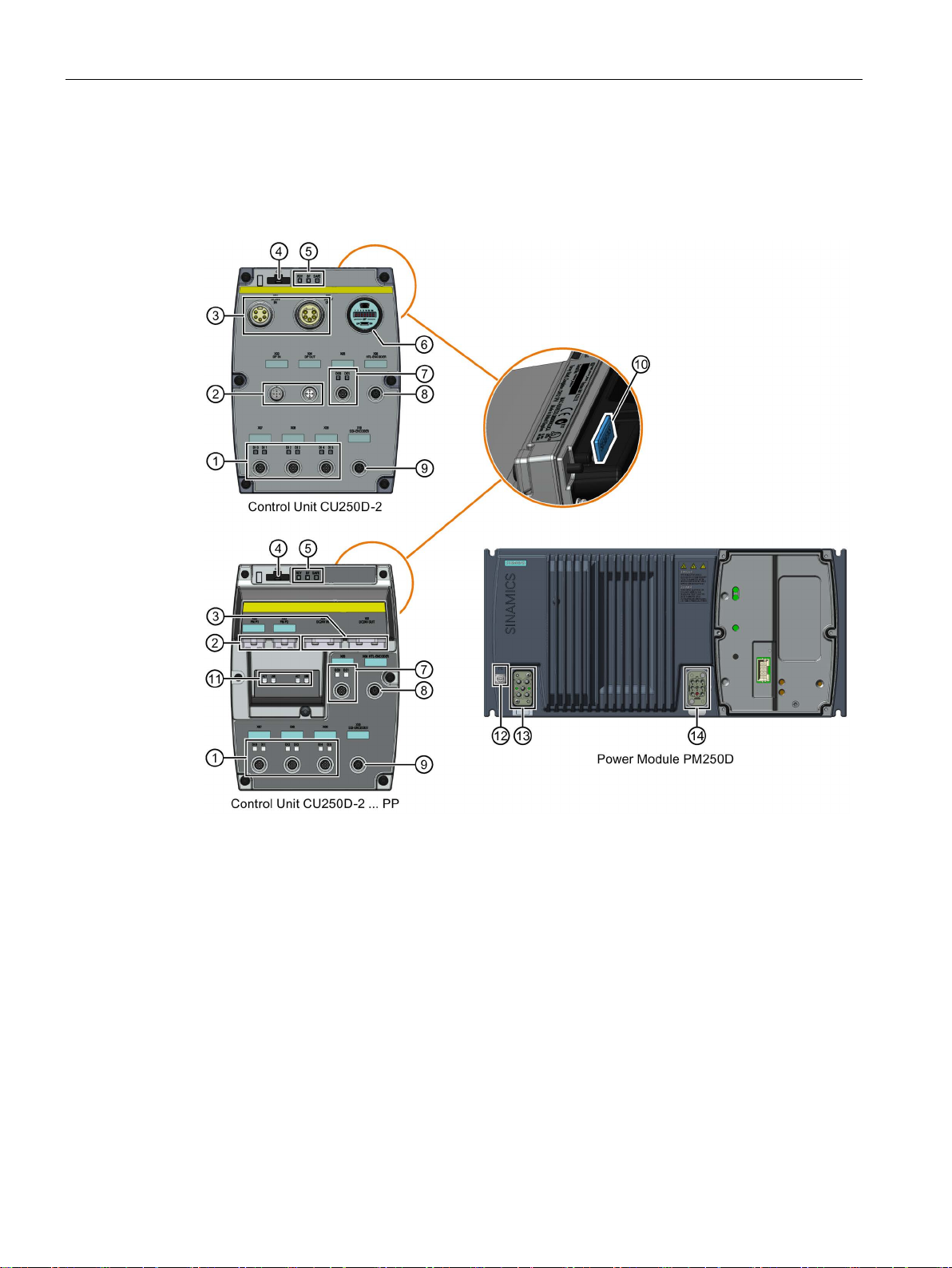
4.2.3
Overview of the interfaces
Interfaces of the converter
①
Digital inputs 0 … 5 with status LED
⑧
HTL Encoder connection
②
PROFIBUS)
⑨
③
⑩
Unit
④
handheld
⑪
⑤
Converter status LED
⑫
PE grounding terminal
⑥
nation switch for PROFIBUS
⑬
⑦
⑭
nections
4.2 Electrical Installation
Fieldbus IN and OUT (PROFINET or
24 V DC supply IN and OUT
Optical interface for operator panel IOP
USB PC connection, address and bus termi-
Digital outputs 0 and 1 with status LED
Figure 4-4 Interfaces on the converter variants
Converter with control units CU250D-2
34 Operating Instructions, 04/2015, FW V4.7.3, A5E34261542B AB
SSI Encoder connection
Slot for a memory card at rear of the Control
PROFINET status LED
Mains supply connection
Motor, brake and temperature sensor con-
Page 35
Installation
4.2.4
Feeder protection of individual inverters
Feeder protection according to IEC
Rated power
Power Module
Frame
size
Article No.
Max. rated
current of the
protection device
Fuse
Circuit-breaker
0.75 kW
6SL3525-0PE17-5AA1
1.5 kW
6SL3525-0PE21-5AA1
3 kW
6SL3525-0PE23-0AA1
FSB
3NA3805
3RV2011-4AA10
16 A
4 kW
6SL3525-0PE24-0AA1
5.5 kW
6SL3525-0PE25-5AA1
7.5 kW
6SL3525-0PE27-5AA1
3NA3812
3RV2021-4PA10
32 A
Feeder protection according to UL standards
Protection device
UL category
SIEMENS circuit breaker
DIVQ
Intrinsically safe SIEMENS circuit breaker
NKJH
4.2 Electrical Installation
If you install a separate 400-V feeder for each inverter, you must protect each feeder
individually.
Figure 4-5 Power supply to inverters through separate 400-V feeders
Table 4- 1 Feeder protection according to IEC
Use in North America requires protection devices that meet UL standards as detailed in the
following tables.
Table 4- 2 Overview of the approved protection devices according to UL standards
Fuses of any manufacturer with faster tripping characteristic than class RK5, e.g.
class J, time, CC, G, or CF
FSA 3NA3803 3RV2011-1JA10 10 A
FSC 3NA3807 3RV2021-4BA10 20 A
JDDZ
Converter with control units CU250D-2
Operating Instructions, 04/2015, FW V4.7.3, A5E34261542B AB
35
Page 36

Installation
Rated power
Power Module
Frame
size
Max. rated current
of the fuse
Short-circuit current rating
SCCR (Short circuit current
rating)
0.75 kW
6SL3525-0PE17-5AA1
10 A
3 kW
6SL3525-0PE23-0AA1
FSB
25 A
4 kW
6SL3525-0PE24-0AA1
35 A
5.5 kW
6SL3525-0PE25-5AA1
45 A
7.5 kW
6SL3525-0PE27-5AA1
60 A
Rated
power
Power Module
Fram
e size
Article No.
UL cat.
Max. rated
current of the
circuit breaker
Short-circuit current
rating SCCR (Short
circuit current rating)
LGG…, or CED6…
3RV2021-1JA…
NKJH
10 A
65 kA, 480 V 3AC
LGG…, or CED6…
3RV2021-1JA…
NKJH
10 A
65 kA, 480 V 3AC
CED6…
3RV2721…
22 A
50 kA, 480 V 3AC
3RV2021-4AA…
16 A
65 kA, 480 V 3AC
3RV1031-4AA…
16 A
65 kA, 480 V 3AC
CED6…
3RV2021-4BA…
20 A
65 kA, 480 V 3AC
3RV.031-4BA…
20 A
65 kA, 480 V 3AC
CED6…
3RV2021-4DA…
25 A
65 kA, 480 V 3AC
3RV.031-4DA…
25 A
65 kA, 480 V 3AC
CED6…
3RV1031-4EA…
32 A
50 kA, 480 V 3AC
3RV2031-4EA…
32 A
65 kA, 480 V 3AC
4.2 Electrical Installation
Table 4- 3 Feeder protection with fuse, UL category JDDZ
FSA
1.5 kW 6SL3525-0PE21-5AA1 15 A
FSC
Table 4- 4 Feeder protection with circuit breaker, UL categories DIVQ and NKJH
0.75 kW 6SL3525-0PE17-5AA1 FSA 3RV2711…, 3RV1742…,
1.5 kW 6SL3525-0PE21-5AA1 FSA 3RV2711…, 3RV1742…,
3 kW 6SL3525-0PE23-0AA1 FSB 3RV1742…, LGG…, or
DIVQ 15 A 65 kA, 480 V 3AC
DIVQ 15 A 65 kA, 480 V 3AC
DIVQ 25 A 65 kA, 480 V 3AC
NKJH
100 kA, 480 V 3AC
4 kW 6SL3525-0PE24-0AA1 FSC 3RV1742…, LGG…, or
5.5 kW 6SL3525-0PE25-5AA1 FSC 3RV1742…, LGG…, or
7.5 kW 6SL3525-0PE27-5AA1 FSC 3RV1742…, LGG…, or
Converter with control units CU250D-2
36 Operating Instructions, 04/2015, FW V4.7.3, A5E34261542B AB
DIVQ 35 A 65 kA, 480 V 3AC
NKJH
DIVQ 45 A 65 kA, 480 V 3AC
NKJH
DIVQ 60 A 65 kA, 480 V 3AC
NKJH
Page 37
Installation
4.2.5
Feeder protection of multiple inverters
Calculation of the feeder protection according to IEC and UL standards
4.2 Electrical Installation
For installations with more than one inverter, the inverters are normally powered from a 400V power bus with a T distributor.
Figure 4-6 Power supply to an inverter group via a shared 400-V feeder
Calculation of the feeder protection:
● Add together the rated input currents of the inverter group.
● The sum of all rated input currents must be ≤ 24 A.
● Use one of the following protection devices for the inverter group:
– Fuse or circuit breaker with a rated current of 30 A
– Intrinsically safe circuit breaker with a rated current of 25 A
The feeder protection also depends on the following conditions:
● Type of cable routing
● Limit values of the cables and system components, e.g. the T distributor.
● Country-specific regulations
If it is precluded that all of the inverters of a group operate simultaneously, it is permissible to
form larger inverter groups on one 400-V feeder. The sum of the rated input currents of all of
the inverters operated simultaneously must always be less than 24 A.
Converter with control units CU250D-2
Operating Instructions, 04/2015, FW V4.7.3, A5E34261542B AB
37
Page 38

Installation
Example
Feeder protection according to IEC
Max. rated current of the protection device
Article No. of the fuse
Article No. of the circuit breaker
30 A
-
3RV1742
4.2 Electrical Installation
In one installation, either the inverters of group ① or the inverters of group ② are in
operation, but never both groups
Figure 4-7 Protection of two inverter groups via a shared 400-V feeder
① and ② simultaneously.
The sum of the rated input currents is:
● Group
● Group
①: 7.2 A + 7.2 A + 9.5 A = 23.9 A ≤ 24 A
①: 17.7 A + 3.8 A + 2.1 A = 23.6 A ≤ 24 A
You can power all the inverters through a shared fuse.
Table 4- 5 Feeder protection according to IEC
25 A 3NA3810 3RV2021…, 3RV1031…,
3RV2031…
Converter with control units CU250D-2
38 Operating Instructions, 04/2015, FW V4.7.3, A5E34261542B AB
Page 39

Installation
Feeder protection according to UL standards
Protection device
UL category
class J, time, CC, G, or CF
SIEMENS circuit breaker
DIVQ
Intrinsically safe SIEMENS circuit breaker
NKJH
Max. rated current of the fuse
Short-circuit current rating SCCR (Short circuit current rating)
Max. rated current of the
circuit breaker
Article No.
UL cat.
Short-circuit
current rating
SCCR (Short
circuit current
rating)
CED6…
3AC
3RV2021-4DA…
3RV.031-4DA10
3AC
4.2 Electrical Installation
Use in North America requires protection devices that meet UL standards as detailed in the
following tables.
Table 4- 6 Overview of the approved protection devices according to UL standards
Fuses of any manufacturer with faster tripping characteristic than class RK5, e.g.
Table 4- 7 Feeder protection with fuse, UL category JDDZ
30 A 65 kA, 480 V 3AC
Table 4- 8 Feeder protection with circuit breaker, UL categories DIVQ and NKJH
30 A 3RV2711…, 3RV1742…, LGG…, or
25 A
22 A 3RV2721… DIVQ 50 kA, 480 V
DIVQ 65 kA, 480 V
NKJH 65 kA, 480 V
JDDZ
3AC
Converter with control units CU250D-2
Operating Instructions, 04/2015, FW V4.7.3, A5E34261542B AB
39
Page 40
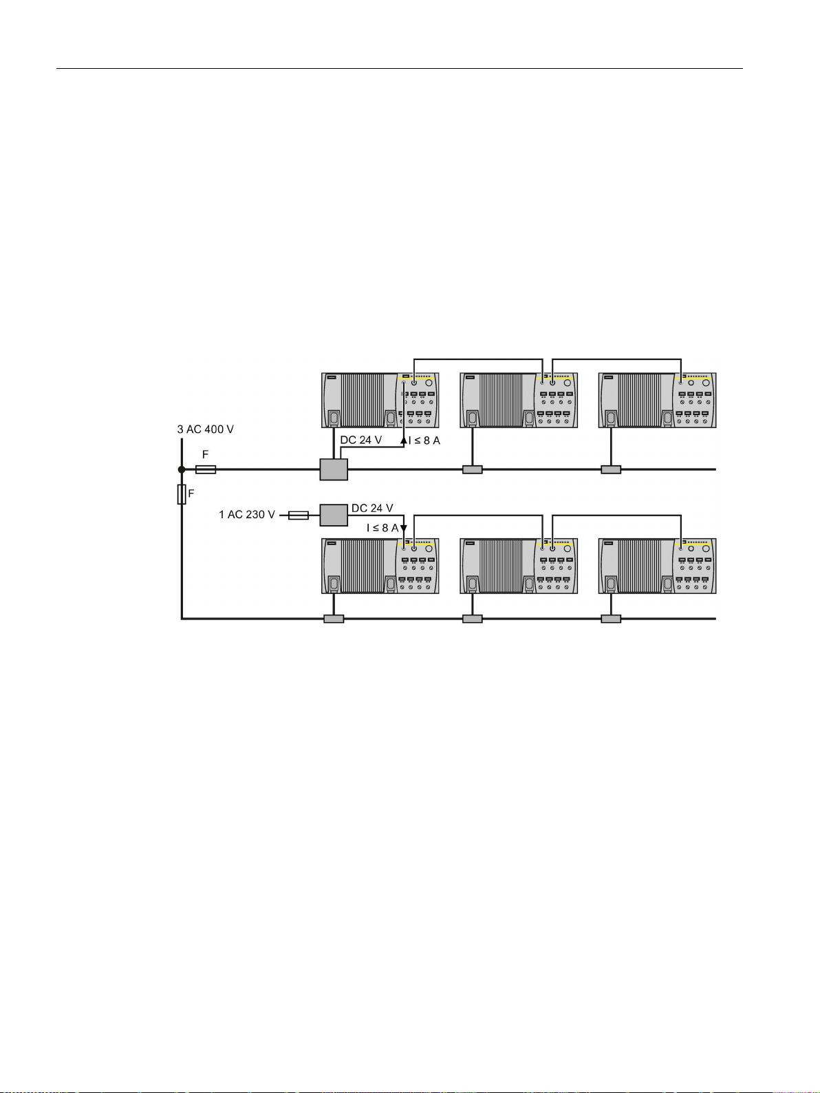
Installation
4.2.6
24-V power supply with multiple inverters
Installation using 24 V bus
4.2 Electrical Installation
The following options are available for the 24 V supply of the inverter:
1. A T distributor with integrated power supply unit supplies the 24 V.
Advantage: Low installation costs.
2. An external power supply unit supplies the 24 V.
Advantage: You can switch off the 400 V without interrupting the 24 V supply and thus
the fieldbus communication of the inverter.
The inverter can conduct a maximum current of 8 A through its 24 V connector.
Figure 4-8 24 V bus from T distributor or with separate power supply
Converter with control units CU250D-2
40 Operating Instructions, 04/2015, FW V4.7.3, A5E34261542B AB
Page 41

Installation
4.2.7
Connections and cables
DANGER
Danger of electrical shock by touching the pins in the motor terminal box
NOTICE
Damage of the converter by disconnecting the motor during operation
Connectors
"Switched" and "unswitched" 24 V power supply
4.2 Electrical Installation
The temperature sensor and motor holding brake connections are at DC link negative
potential. Touching the pins in the motor terminal box can lead to death due electrical
shock.
• Keep the motor terminal box closed whenever the mains is applied to the converter.
• Insulate the cables that are not used.
• Use appropriate insulation on the cables.
The disconnection of the motor cable by a switch or contactor during operation may
damage the converter.
• Disconnect converter and motor during operation only if it is necessary in terms of
personal security or machine protection.
The unswitched 24 V power supply (1L+) is required for the device to function.
The switched 24 V (2L+) supplies the two digital outputs. Switching brings all of the actuators
connected to the digital outputs into the no-voltage state.
If you don't need the switching of 2L+ power supply, then both the switched as well as the
non-switched 24 V may come from the same supply.
Converter with control units CU250D-2
Operating Instructions, 04/2015, FW V4.7.3, A5E34261542B AB
41
Page 42

Installation
4.2 Electrical Installation
Figure 4-9 G120D CU250D-2 PROFIBUS connectors
Converter with control units CU250D-2
42 Operating Instructions, 04/2015, FW V4.7.3, A5E34261542B AB
Page 43
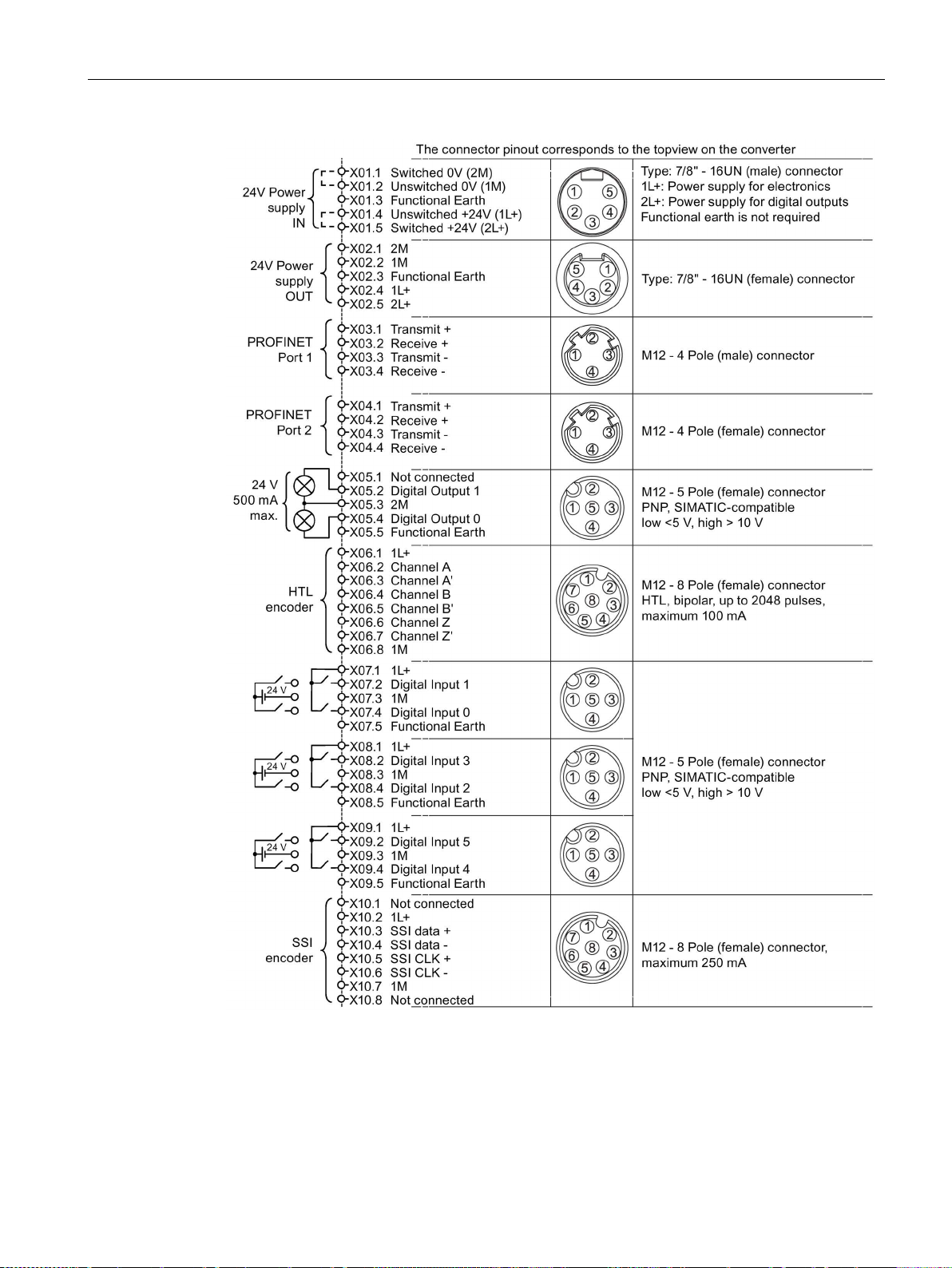
Installation
4.2 Electrical Installation
Figure 4-10 G120D CU250D-2 PROFINET connectors
Converter with control units CU250D-2
Operating Instructions, 04/2015, FW V4.7.3, A5E34261542B AB
43
Page 44

Installation
4.2 Electrical Installation
Figure 4-11 G120D CU250D-2 PROFINET Push-Pull connectors
Converter with control units CU250D-2
44 Operating Instructions, 04/2015, FW V4.7.3, A5E34261542B AB
Page 45

Installation
4.2 Electrical Installation
Figure 4-12 G120D CU250D-2 PROFINET FO terminal diagram
Converter with control units CU250D-2
Operating Instructions, 04/2015, FW V4.7.3, A5E34261542B AB
45
Page 46

Installation
Cable, connectors and tools specifications
Note
NFPA compatibility
These devices are intended only for installation on industrial machines in accordance with
the "Electrical Standard
devices they may not be suitable for installation accordance with the "National Electrical
Code" (NFPA70).
Order number
Crimp tool (Q8/0 and Q4/2)
3RK1902-0AH00
Removal tool (Q8/0)
3RK1902-0AJ00
Removal tool (Q4/2)
Harting part number 0999-000-0305
No special tools are required for the Control Unit connectors
4.2 Electrical Installation
Figure 4-13 PM250D connectors
The detailed specifications for the cables, connectors and tools required to manufacture the
necessary cables for the SINAMICS G120D are listed in the following tables. The
connections that are detailed in this section relate to the physical connections that exist on
the Inverter. Information for the preparation and construction of the individual connectors
have separate detailed instructions delivered with the ordered parts, direct from the
manufacturers. Use 75 °C copper wire only.
for Industrial Machinery" (NFPA79). Due to the nature of these
Table 4- 9 Tools
Converter with control units CU250D-2
46 Operating Instructions, 04/2015, FW V4.7.3, A5E34261542B AB
Page 47

Installation
Connector
Order number
Straight connector
Right-angle connector
24 V DC power supply Out (7/8" )
6GK1905-0FA00
3RK1902-3BA00
PROFIBUS Out (M12 )
6GK1905-0EA00
3RK1902-1BA00
PROFINET Port 1 and Port 2 (M12)
6GK1901-0DB20-6AA0
3RK1902-2DA00
profile/siemens-solution-partner)
Digital input and output (M12 )
3RK1902-4BA00-5AA0
3RK1902-4DA00-5AA0
Connector
Order number
24 V DC power supply
6GK1907-0AB10-6AA0
RJ45 PROFINET
6GK1901-1BB10-6AA0
Connector
Order number
IE SC RJ POF PLUG PRO
6GK1900-0MB00-6AA0
IE SC RJ PCF PLUG PRO
6GK1900-0NB00-6AA0
Power rating
cable size
Order number
0.75 kW … 1.50 kW
2.5 mm2 (14 AWG)
3RK1911-2BE50
3.00 kW … 4.00 kW
4 mm2 (12 or 10 AWG)
3RK1911-2BE10
5.50 kW … 7.50 kW
6 mm2 (10 AWG)
3RK1911-2BE30
4.2 Electrical Installation
Table 4- 10 Control unit connectors
24 V DC power supply In (7/8" ) 6GK1905-0FB00 3RK1902-3DA00
PROFIBUS In (M12 ) 6GK1905-0EB00 3RK1902-1DA00
Encoder (M12 ) Via KnorrTec: Knorrtec
(http://www.knorrtec.de/index.php/en/company-
Table 4- 11 Push-Pull variant PROFINET and POWER connectors
Table 4- 12 Fibre optic connectors
Table 4- 13 Mains connector
Order motor connector including temperature sensor and motor holding brake via solution
partner: Solution partner
(https://www.automation.siemens.com/solutionpartner/partnerfinder/Partner-
Finder.aspx?lang=en)
Converter with control units CU250D-2
Operating Instructions, 04/2015, FW V4.7.3, A5E34261542B AB
47
Page 48

Installation
Cable lengths
Cable
Screening
Max. length
Screened
15 m (49 ft)
Screened
15 m (49 ft)
Unscreened
30 m (98 ft)
Screened
15 m (49 ft)
Unscreened
30 m (98 ft)
Digital inputs
Screened
30 m (98 ft)
Digital outputs
Screened
30 m (98 ft)
Encoder (SSI and HTL)
Screened
30 m (98 ft)
1)
cable which is connected to the Power Module using a Harting connector.
4.2 Electrical Installation
1)
Motor
Temperature sensor
Unscreened 30 m (98 ft)
1)
Motor holding brake
1)
The motor, temperature sensor and motor holding brake connections are all carried in a single
Converter with control units CU250D-2
48 Operating Instructions, 04/2015, FW V4.7.3, A5E34261542B AB
Page 49
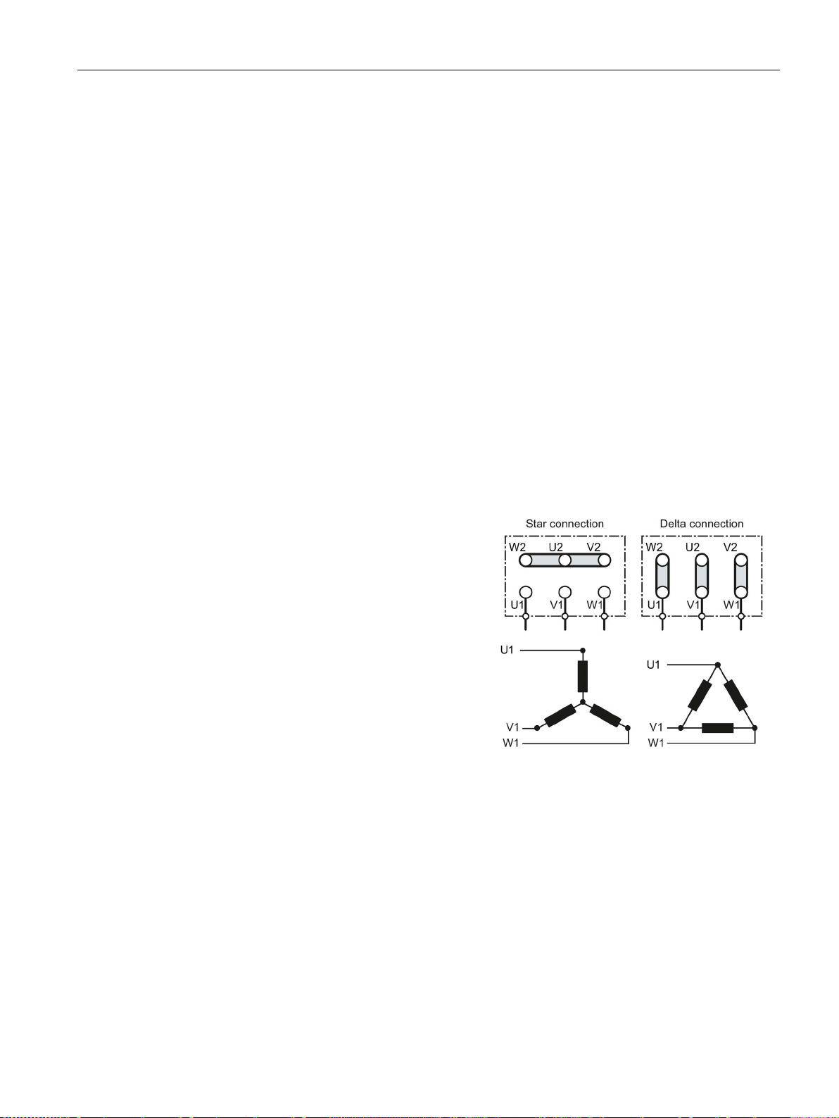
Installation
4.2.8
Star-delta motor connection
Examples for operating the converter and motor on a 400 V line supply
Motor is connected in the star or delta configuration
With SIEMENS motors, you will see a diagram
of both connection methods on the inside of the
cover of the terminal box:
•
•
4.2 Electrical Installation
Depending on your application, you can operate the motor in the star or delta connection
(Y/Δ).
Assumption: The motor rating plate states 230/400 V Δ/Y.
Case 1: A motor is normally operated between standstill and its rated speed (i.e. a speed
corresponding to the line frequency). In this case, you need to connect the motor in Y.
Operating the motor above its rated speed is only possible in field weakening, i.e. the motor
torque available is reduced above the rated speed.
Case 2: If you want to operate the motor with the "87 Hz characteristic", you need to connect
the motor in Δ.
With the 87 Hz characteristic, the motor's power output increases. The 87 Hz characteristic
is mainly used with geared motors.
Before you connect the motor, ensure that the motor has the appropriate connection for your
application:
Star connection (Y)
Delta connection (Δ)
Converter with control units CU250D-2
Operating Instructions, 04/2015, FW V4.7.3, A5E34261542B AB
49
Page 50
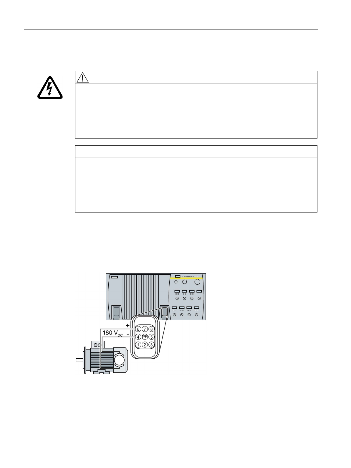
Installation
4.2.9
Connecting the motor holding brake
WARNING
NOTICE
Device damage by earthing the motor cable
4.2 Electrical Installation
Danger to life when live parts are touched in the motor terminal box
The temperature sensor and motor holding brake connections are at DC link negative
potential. Touching these connections can result in death or severe injury.
• Keep the motor terminal box closed whenever the mains is applied to the converter.
• Use appropriate insulation on the cables.
• Insulate cables that are not used
The temperature sensor and motor holding brake connections are at DC link negative
potential. Earthing these connections will damage the device.
• Use appropriate insulation on the cables.
• Insulate cables that are not used.
• Do not earth cables that are not used.
The brake is connected to the converter using Pin 4 - Brake (-) and Pin 6 - Brake (+) of the
motor connector.
The converter supplies 180 V DC to the brake.
The brake supply is suitable for brakes which require 400 V AC with rectifier. Remove the
rectifier module and connect the brake output of the converter directly to the brake coil.
Figure 4-14 Principle of connectiong the motor holding brake to the converter
Converter with control units CU250D-2
50 Operating Instructions, 04/2015, FW V4.7.3, A5E34261542B AB
Page 51

Installation
4.2.10
Factory settings of the inputs and outputs
Factory settings of the inputs and outputs of the CU250D-2 control unit
Changing the function of the inputs and outputs
4.2 Electrical Installation
In the factory settings, the fieldbus interface of the inverter is not active.
Figure 4-15 Factory settings of the CU250D-2 control units
The function of each color-identified input and output can be set.
To avoid having to change each input individually, you can set multiple inputs and outputs
together using default settings.
The factory setting of the inputs and outputs described above corresponds to the default
setting 7 (switchover between fieldbus and a jog using DI 3).
See also: Default settings of inputs and outputs (Page 52).
Converter with control units CU250D-2
Operating Instructions, 04/2015, FW V4.7.3, A5E34261542B AB
51
Page 52
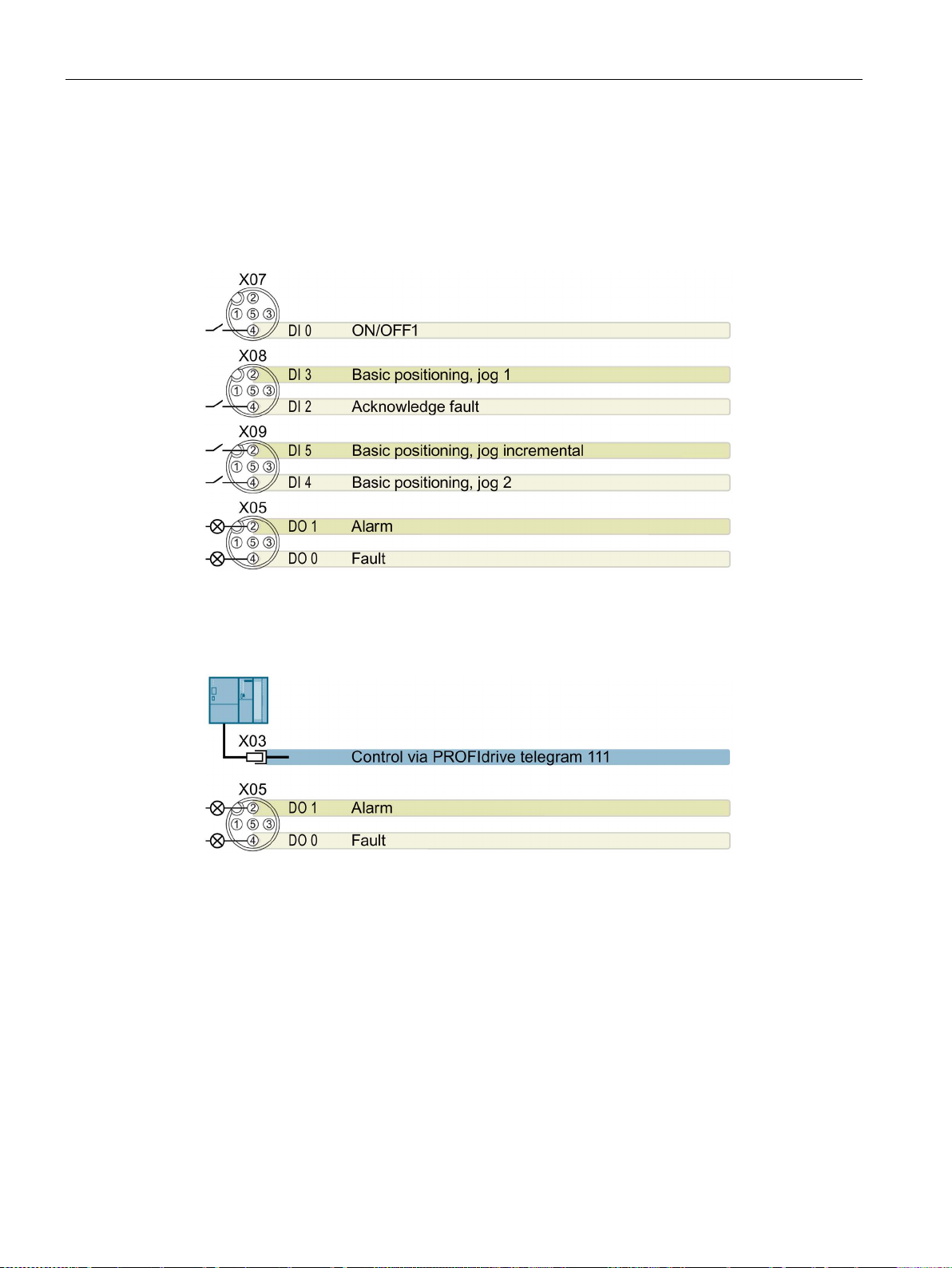
Installation
4.2.11
Default settings of inputs and outputs
Default setting 26: "EPOS without fieldbus"
DO 0: p0730, DO 1: p0731
DI 0: r0722.0, …, DI 5: r0722.5
Default setting 27: "EPOS with fieldbus"
DO 0: p0730, DO 1: p0731
4.2 Electrical Installation
Factory setting
Converter with control units CU250D-2
52 Operating Instructions, 04/2015, FW V4.7.3, A5E34261542B AB
Page 53

Installation
4.2.12
Connecting the PROFINET interface
Industrial Ethernet Cables and cable length
Max. Cable Length
Order Number
Industrial Ethernet FC TP Standard Cable GP 2 x 2
100 m (328 ft)
6XV1840-2AH10
Industrial Ethernet FC Trailing Cable GP 2 x 2
85 m (278 ft)
6XV1870–2D
Industrial Ethernet FC Trailing Cable 2 x 2
85 m (278 ft)
6XV1840–3AH10
Industrial Ethernet FC Marine Cable 2 x 2
85 m (278 ft)
6XV1840–4AH10
Cable screening
4.2.13
Encoders examples
Examples
Manufacturer
Type / order number
Details
Setting
Note
6FX2001-5xS24
CEV-65
AFM60…
Single- and multiturn
grammable encoder
Heidenhain
EQN 425
Multiturn
4.2 Electrical Installation
Listed in the table below are the recommended Ethernet cables.
Table 4- 14 Recommended PROFINET cables
Industrial Ethernet FC TP Flexible Cable GP 2 x 2 85 m (278 ft) 6XV1870–2B
The screen of the PROFINET cable must be connected with the protective earth. The solid
copper core must not be scored when the insulation is removed from the core ends.
The following SSI encoders have been commissioned successfully in several applications
with the CU250D-2:
Table 4- 15 SSI encoders
SIEMENS 6FX2001-5xS12 Singleturn encoder p0400 = 3081 --SIEMENS 1XP80X4-20 /
T&R CEW-58, CEV-58,
CEH-58, CEW-65;
SICK / Stegmann
DME4000 Laser distance
Multiturn encoder p0400 = 3082
Programmable encoder
measuring unit, pro-
p0400 = 9999.
Set the encoder
data manually.
We can not guarantee the function of these
encoders in any
circumstance.
Converter with control units CU250D-2
Operating Instructions, 04/2015, FW V4.7.3, A5E34261542B AB
53
Page 54

Installation
4.2.14
Grounding converter and motor
Grounding the converter
•
•
•
•
•
Grounding the motor
4.2 Electrical Installation
● Ground the converter via the PE connection in the mains supply connector.
● Ground the connectors as shown in the diagram below.
Figure 4-16 Grounding the line supply and motor connectors
Connect the PE terminal on the left-hand
side of the converter to the metal frame it is
mounted on.
Recommended cable cross section: 10 mm²
Use a short wire connection preferably.
Clean the connection to the steel
construction from paint or dirt.
Use a ring clamp to ensure a good physical
connection which is resistant to accidental
disconnection.
Converter with control units CU250D-2
54 Operating Instructions, 04/2015, FW V4.7.3, A5E34261542B AB
● Ground the motor via the PE connection in the motor connector.
● Ground the connector as shown in the diagram above (grounding the converter).
Although the line and motor connectors are of a different type, the principle of grounding
them is the same.
● If possible, ground the motor housing.
Page 55
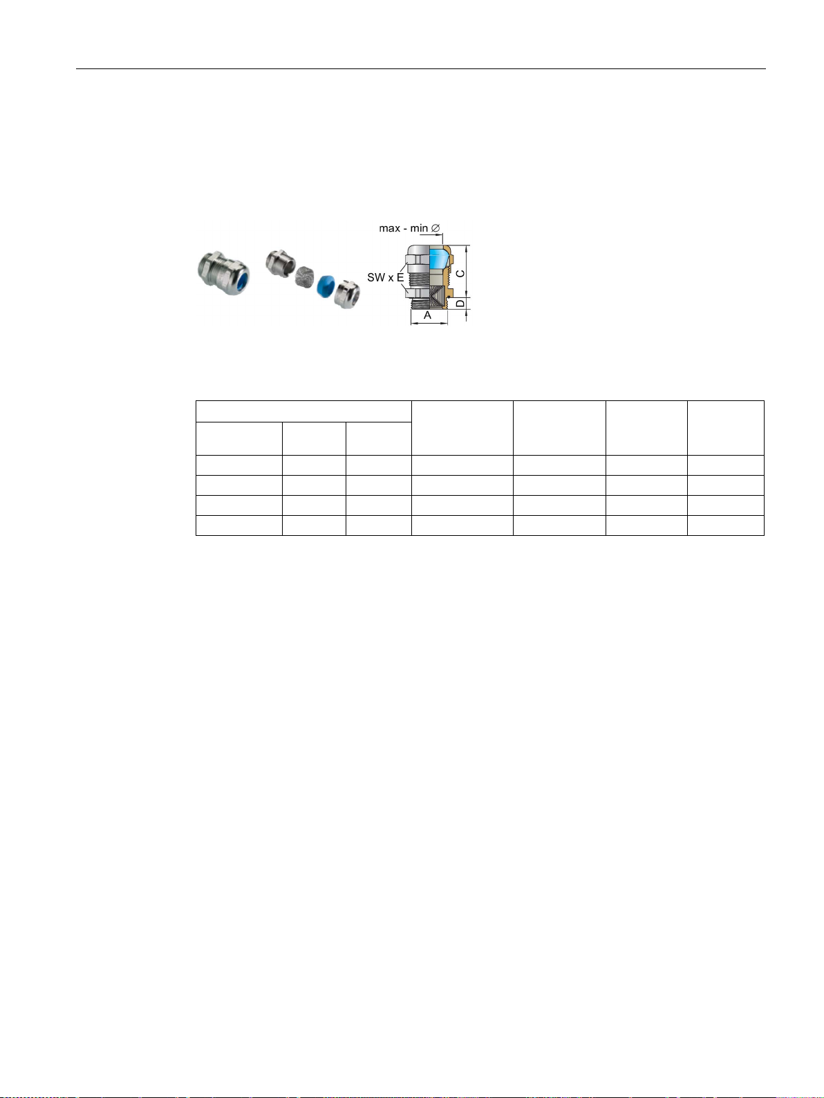
Installation
EMC cable glands
Connection thread/length
Clamping range
without inlet
max/min [mm]
Clamping
range max/min
[mm]
Spanner
width SW *
E
Order No.
A
D [mm]
C [mm]
M16 x 1.5
6.0
29
11 … 7
9 … 7
20 x 22.2
bg216mstri
M20 x 1.5
6.5
29
14 … 9
12 … 7
24 x 26.5
bg220mstri
M25 x 1.5
7.5
29
20 … 13
16… 10
30 x 33
bg255mstri
M32 x 1.5
8.0
32
25 … 20
20 … 13
36 x 39.5
bg232mstri
4.2.15
Connections and interference suppression
4.2 Electrical Installation
Where cable glands are used within the installation of the system, it is recommended that
EMC glands are used.
The cable gland provides protection to the IP68 standard when fitted correctly.
Figure 4-17 Example of a Blueglobe EMC cable gland
Table 4- 16 Brass-nickel plated EMC cable gland with metric thread as per EN50262.
All connections should be made so that they are permanent. Screwed connections on
painted or anodized metal components must be made either by means of special contact
washers, which penetrate the isolating surface and establish a metallically conductive
contact, or by removing the isolating surface on the contact points.
Contactor coils, relays, solenoid valves, and motor holding brakes must have interference
suppressors to reduce high-frequency radiation when the contacts are opened (RC elements
or varistors for AC currentoperated coils, and freewheeling diodes for DC current-operated
coils). The interference suppressors must be connected directly on each coil.
Converter with control units CU250D-2
Operating Instructions, 04/2015, FW V4.7.3, A5E34261542B AB
55
Page 56

Installation
4.2.16
Equipotential bonding
Grounding and high-frequency equipotential bonding measures
4.2 Electrical Installation
Equipotential bonding within the drive system has to be established by connecting all
electrical and mechanical drive components (transformer, motor and driven machine) to the
grounding system. These connections are established by means of standard heavy-power
PE cables, which do not need to have any special high-frequency properties.
In addition to these connections, the inverter (as the source of the high-frequency
interference) and the motor must be interconnected with respect to the high-frequency point
of view:
1. Use a shielded motor cable.
2. Connect the cable shield both to the motor connector on the inverter and to the motor
terminal box.
3. Use a short grounding connection from the PE terminal on the inverter to the metal frame.
The following figure illustrates all grounding and high-frequency equipotential bonding
measures using an example.
Converter with control units CU250D-2
56 Operating Instructions, 04/2015, FW V4.7.3, A5E34261542B AB
Page 57

Installation
①
Transformer
②
Second level distribution with PE equipotential bonding
③
Metal frame
④
Short connection from the PE terminal to the metal frame.
⑤
Electrical connection of motor cable shield and connector body.
⑥
shield and motor terminal box via electrically conductive PG
gland.
⑦
Driven machine
⑧
⑨
Foundation ground
4.2 Electrical Installation
Electrical connection of motor cable
Conventional grounding system.
• Standard, heavy-power PE conductors without special high-frequency properties.
• Ensures low frequency equipotential bonding as well as protection against injury.
Figure 4-18 Grounding and high-frequency equipotential bonding measures in the drive system and
in the plant
For general rules for EMC compliant installation see also: EMC design guidelines
(http://support.automation.siemens.com/WW/view/en/60612658/0/en)
Converter with control units CU250D-2
Operating Instructions, 04/2015, FW V4.7.3, A5E34261542B AB
57
Page 58

Installation
4.2 Electrical Installation
Converter with control units CU250D-2
58 Operating Instructions, 04/2015, FW V4.7.3, A5E34261542B AB
Page 59
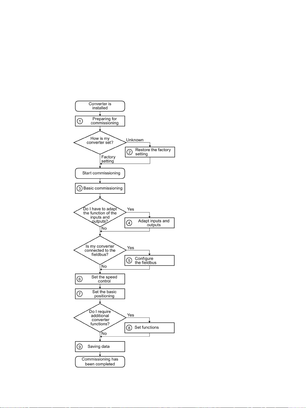
5
5.1
Commissioning guidelines
Explanation of the commissioning steps:
①
Preparing for commissioning
(Page 60)
Res
(Page 82)
③
Basic commissioning with
STARTER
Panel (Page 65)
Adapt inputs and outputs
(Page 115)
Adapt fieldbus configuration
(Page 87)
⑥
Mo
Basic positioner and position co
(Page 163)
⑧
Advanced commissioning
(Page 113)
Backing up data and series co
missioning (Page 275)
The converter must match the motor and the drive application to be able to optimally operate
and protect the motor. We recommend a certain procedure when commissioning your
converter.
②
toring the factory setting
(Page 69) orOperator
④
⑤
tor control (Page 143)
⑦
⑨
ntrol
m-
Converter with control units CU250D-2
Operating Instructions, 04/2015, FW V4.7.3, A5E34261542B AB
59
Page 60

Commissioning
5.2
Preparing for commissioning
Overview
Inverter
What are the data specifications of my inverter?
What inverter interfaces are active?
How is the inverter integrated in the higher-level control system?
What technological requirements must the drive fulfill?
Which motor is connected to the inverter?
In which region of the world is the motor to be used?
How is the motor connected?
5.2 Preparing for commissioning
Before starting commissioning, you must know the answer to the following questions:
●
→ SINAMICS G120D CU250D-2 Inverter (Page 23).
●
→ Connections and cables (Page 41).
●
●
→ Introduction, V/f control, vector control (Page 62).
→ Defining additional requirements for the application (Page 63).
Before starting commissioning, you must know the following data:
●
Note down the Article No. of the motor and the motor’s nameplate data.
If available, note down the motor code on the motor’s nameplate.
●
- Europe IEC: 50 Hz [kW]
- North America NEMA: 60 Hz [hp] or 60 Hz [kW]
●
Pay attention to the connection of the motor (star connection [Y] or delta connection [Δ]).
Note the appropriate motor data for connecting.
Converter with control units CU250D-2
60 Operating Instructions, 04/2015, FW V4.7.3, A5E34261542B AB
Page 61

Commissioning
5.2.1
Which motor fits the converter?
Ratio of the motor and inverter rated currents
5.2 Preparing for commissioning
The rated current of the motor must be in the range 13% to 100% of the rated converter
current.
Example: With an inverter with a rated current of 10.2 A, you can operate motors whose
rated currents are within the range of 1.3 A … 10.2 A.
Figure 5-1 The rated currents of inverter and motor match
Converter with control units CU250D-2
Operating Instructions, 04/2015, FW V4.7.3, A5E34261542B AB
61
Page 62
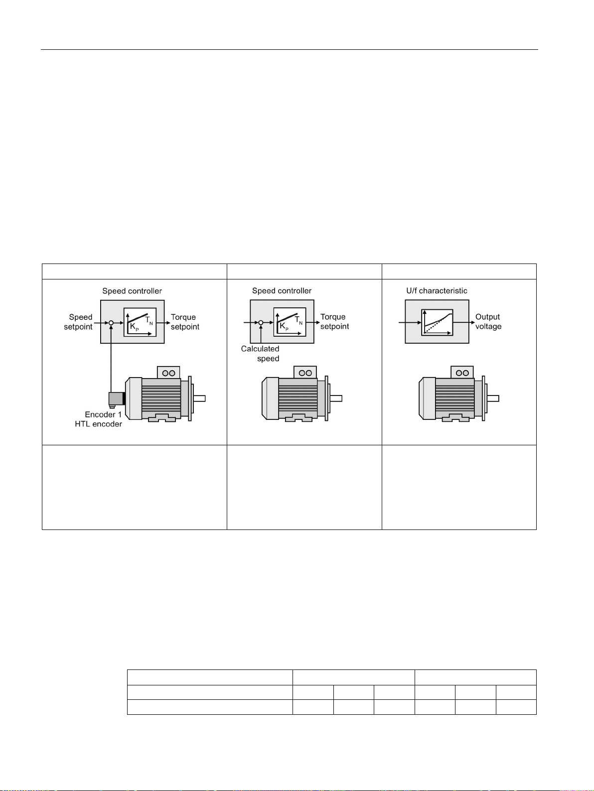
Commissioning
5.2.2
Introduction, V/f control, vector control
Specifying the control mode
Vector control with encoder
Sensorless vector control
U/f control
It is not permissible to use vector control in the following cases:
Inverter pulse frequency
2 kHz
4 kHz and higher
Pole number of the motor
2-pole
4-pole
6-pole
2-pole
4-pole
6-pole
Maximum motor speed [rpm]
9960
4980
3320
14400
7200
4800
5.2 Preparing for commissioning
The converter has three open-loop control and closed-loop control modes for induction
motors:
● Open-loop control with U/f-characteristic (U/f control)
● Field-oriented control (sensorless vector control)
● Speed control (vector control with encoder)
The control modes have different degrees of suitability when it comes to controlling a
position-controlled axis:
With the position control, provides the best
results
Limited functionality of the position
control.
• Low accuracy
• Travel to fixed stop is not possi-
ble
● If the motor is too small in comparison to the inverter (the rated motor power may not be
less than one quarter of the rated inverter power)
● If several motors are connected to one inverter
● If a power contactor is used between the inverter and motor and is opened while the
motor is powered up
● If the maximum motor speed exceeds the following values:
Not recommended in conjunction
with position control.
• Low accuracy
• Low dynamic response
• Travel to fixed stop is not possi-
ble
Converter with control units CU250D-2
62 Operating Instructions, 04/2015, FW V4.7.3, A5E34261542B AB
Page 63
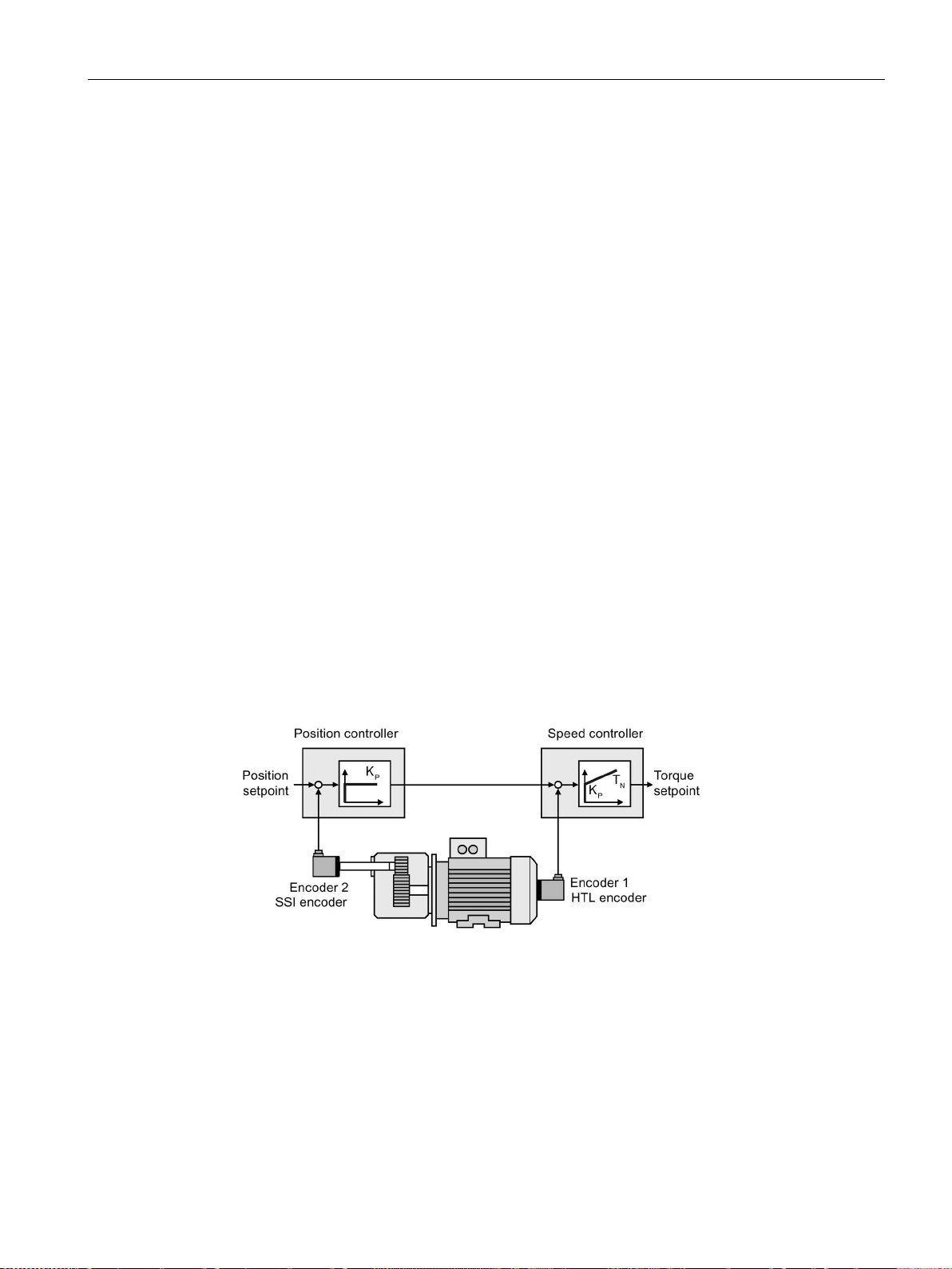
Commissioning
5.2.3
Defining additional requirements for the application
What speed limits should be set (minimum and maximum speed)?
What motor ramp-up time and ramp-down time are needed for the application?
5.2.4
Encoder assignment
Description
Position controller operates with SSI encoder, speed controller with HTL encoder
5.2 Preparing for commissioning
● Minimum speed - factory setting 0 [rpm]
The minimum speed is the lowest speed of the motor independent of the speed setpoint.
A minimum speed is, for example, useful for fans or pumps.
● Maximum speed - factory setting 1500 [rpm]
The inverter limits the motor speed to this value.
The ramp-up and ramp-down time define the maximum motor acceleration when the speed
setpoint changes. The ramp-up and ramp-down time is the time between motor standstill and
the maximum speed, or between the maximum speed and motor standstill.
● Ramp-up time - factory setting 10 s
● Ramp-down time - factory setting 10 s
The converter offers three options of allocating encoders to the closed-loop control on the
motor and load side.
Figure 5-2 SSI encoder on the load side for the position controller, HTL encoder on the motor axis
for the speed controller
Compared to the other options, the encoder assignment provides this configuration with the
best control results.
Converter with control units CU250D-2
Operating Instructions, 04/2015, FW V4.7.3, A5E34261542B AB
63
Page 64
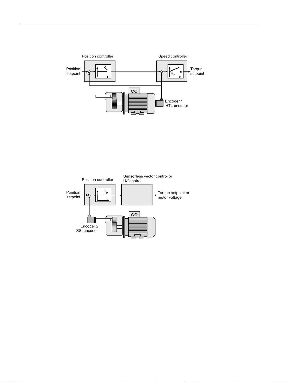
Commissioning
Position and speed controllers operating with HTL encoder
Advantage:
Favorably-priced solution.
Disadvantage:
Depending on the gear ratio, restrictions regarding the accuracy of the
position control.
Position controller operates with SSI encoder, speed controller without an encoder
Advantage:
Favorably
Disa
•
•
5.2 Preparing for commissioning
Figure 5-3 HTL encoder on the motor axis for position and speed controllers
Figure 5-4 SSI encoder on the load side for the position controller, speed controller without an
encoder
dvantages:
Restrictions regarding the accuracy and dynamic performance of the
-priced solution.
position control
Travel to fixed stop is not possible.
Converter with control units CU250D-2
64 Operating Instructions, 04/2015, FW V4.7.3, A5E34261542B AB
Page 65

Commissioning
5.3
Basic commissioning with IOP
Basic commissioning wizard
Procedure
1. Select "Basic Commissioning..." from the Wizards
menu.
2. Select "Yes" or "No" to a factory reset.
The factory reset is performed prior to saving all the
parameter changes that have been made during the
basic commissioning proces
3. Select the Control Mode for the attached motor.
4. Select th
tached motor.
This data is used to calulate the correct speed and di
played values for the application.
5.3 Basic commissioning with IOP
The Basic Commissioning wizard detailed below is for Control Units with version 4.4
software or higher.
For performing the basic commissioning of the converter with the IOP operator panel,
proceed the following steps:
s.
e correct Motor Data for your Inverter and at-
s-
Converter with control units CU250D-2
Operating Instructions, 04/2015, FW V4.7.3, A5E34261542B AB
65
Page 66
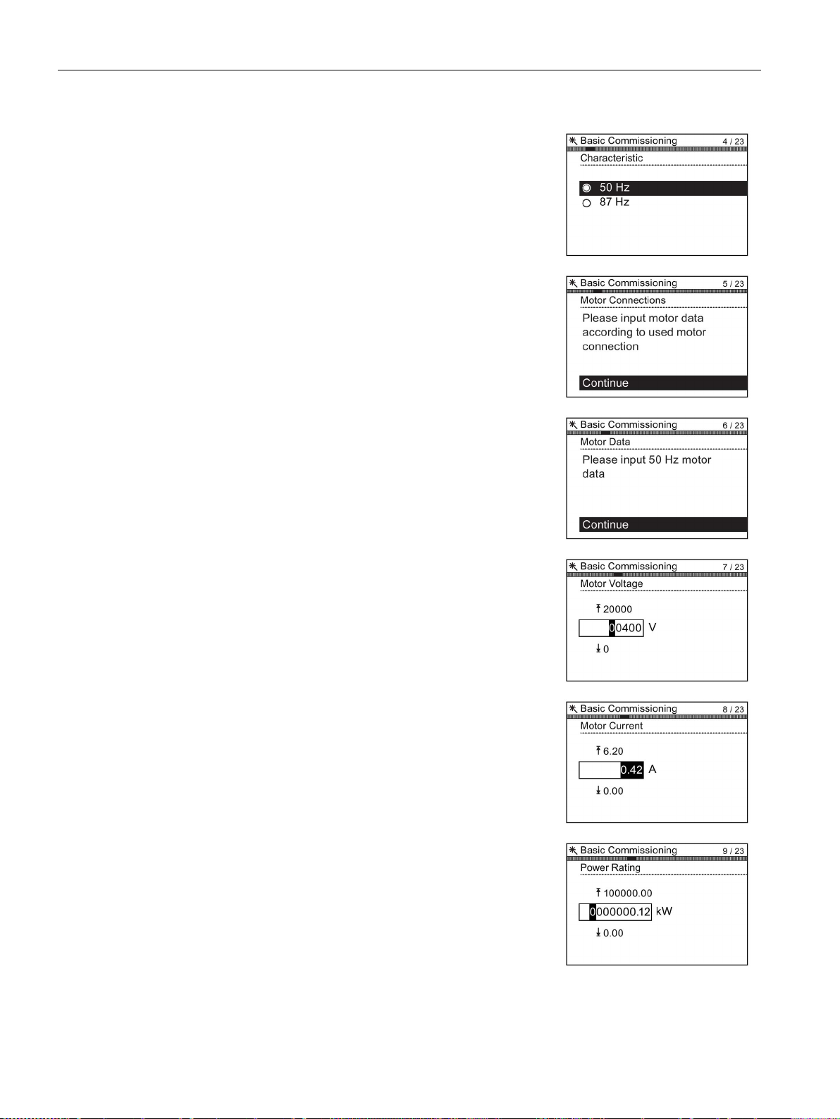
Commissioning
5. Select th
tached motor.
The use of the 87 Hz characteristic allows the motor to
operate at 1.73 times of its normal speed.
6. A
relating specifically to the attached motor. The data is
obtained from the motor rating plate.
7. The Moto
teristic of the attached motor.
8. Input the correct Motor Voltage from the motor rating
plate.
9. Input the correct Motor Current from the motor rating
plate.
10. Input the correct P
plate.
5.3 Basic commissioning with IOP
e correct frequency for your Inverter and at-
t this stage the wizard will begin to ask for the data
r Data screen indicates the frequency charac-
ower Rating from the motor rating
Converter with control units CU250D-2
66 Operating Instructions, 04/2015, FW V4.7.3, A5E34261542B AB
Page 67
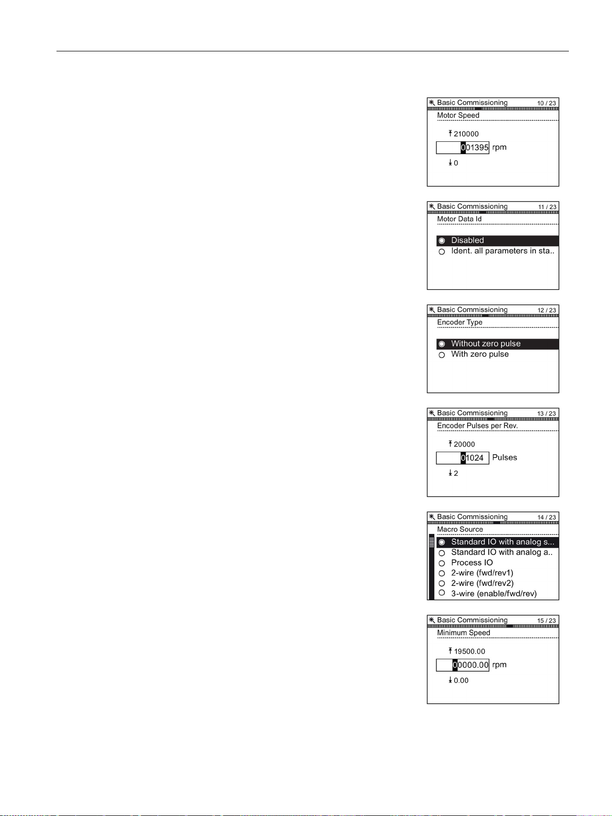
Commissioning
11. Input the correct Motor Speed from the motor rating
plate.
This value is given in RPM.
12. Select to run or disable Motor Data Identification fun
tion.
This function, if active, will not start until the first run
command is given to the Inverter.
13. Select either zero pulse on no zero pulse for the a
tached encoder.
If no encoder is fitted to the motor, the option will not be
displayed.
14. Enter the correct pulses per revolution for the encoder.
This information is normally printed on the casing of the
encoder.
15. Select the macro that is suitable for your application.
Once selected all inputs, outputs, command sources
and setpoints will be automatically configured by the
software.
For further information see the section that details the
precise s
section of this manual.
16. Set the Minimum Speed at which the attached motor
should run.
5.3 Basic commissioning with IOP
c-
t-
ettings for each macro. Please see installation
Converter with control units CU250D-2
Operating Instructions, 04/2015, FW V4.7.3, A5E34261542B AB
67
Page 68
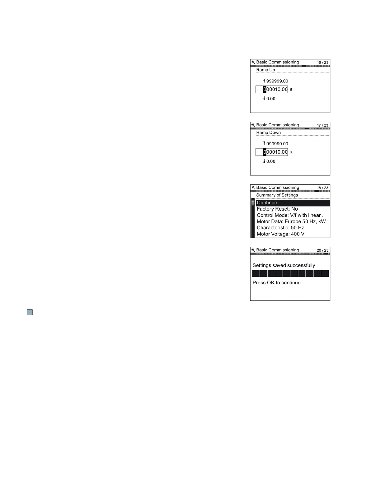
Commissioning
17. Set the Ramp Up time in seconds.
This is the time the Inverter/motor system will take from
being given the run command, to reaching the selected
motor speed.
18. Set the Ramp Down time in seconds.
This is the time the Inverter/motor system will take from
being given the OFF1 command, for the motor to reach
a standstill.
19. A summary of all the settings is display.
If the settings are correct, select Continue.
20. The final screen gives two options:
•
•
If save is selected, a factory reset will be performed then
the settings are saved to the Inverter memory. The loc
tion of safe data is assigned using the "Parameter sa
ing mode" fu
5.3 Basic commissioning with IOP
Save settings
Cancel Wizard
nction in "Parameter settings" in "Menu".
The basic commissioning of your converter is finished.
a-
v-
Converter with control units CU250D-2
68 Operating Instructions, 04/2015, FW V4.7.3, A5E34261542B AB
Page 69
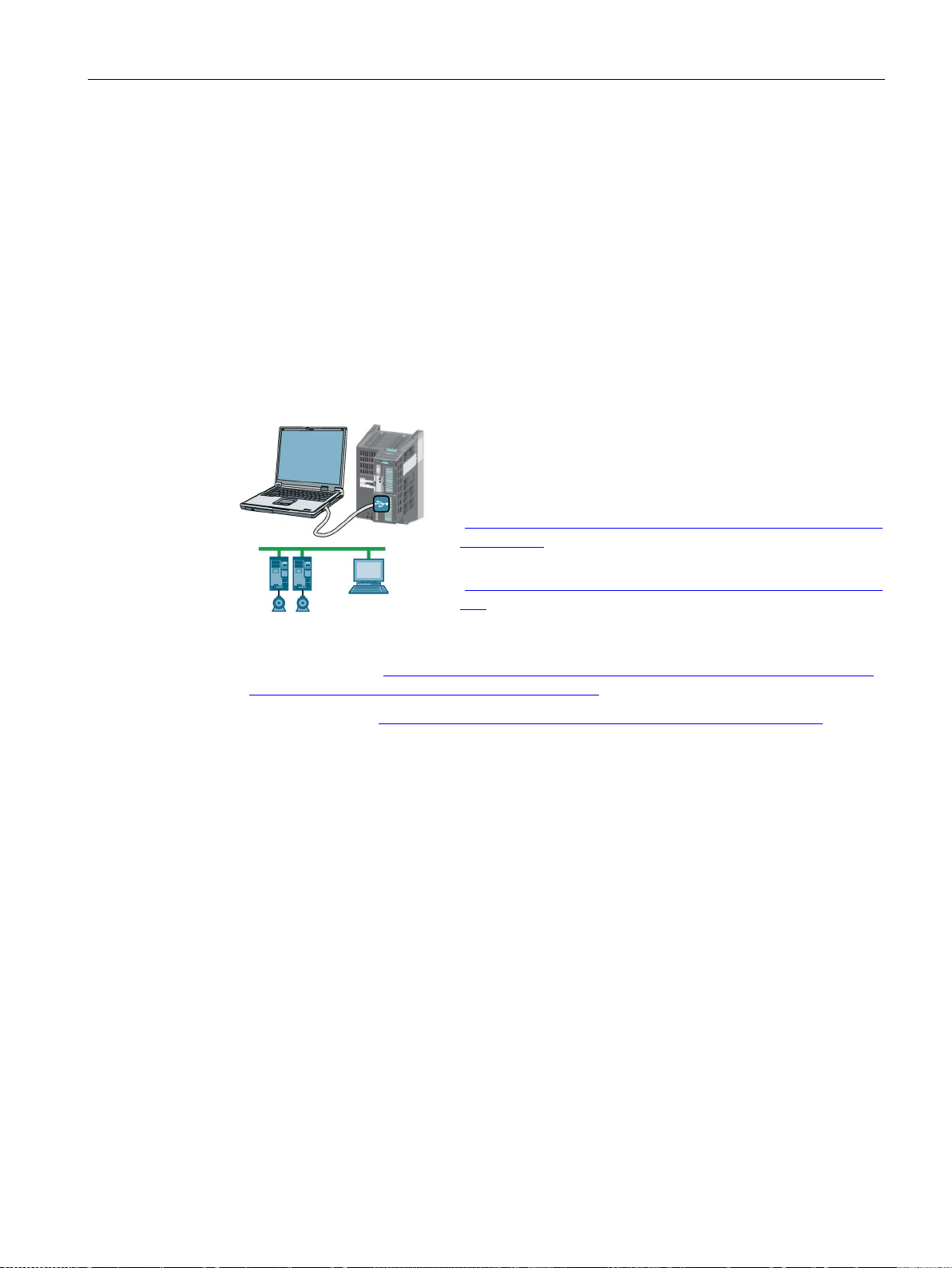
Commissioning
5.4
Basic commissioning with a PC
PC-based commissioning tools
Preconditions for commissioning
You can access the inverter with STARTER or Startdrive either
via a USB connection or via the fieldbus.
System requirements and download:
•
•
Overview of basic commissioning
5.4 Basic commissioning with a PC
STARTER and Startdrive are PC tools to commission Siemens inverters. The graphic user
interface supports you when commissioning your inverter. Most of the inverter functions are
available in screen forms.
The screen forms that are shown in this manual show generally valid examples. The number
of setting options available in screen forms depends on the particular inverter type.
STARTER download
(http://support.automation.siemens.com/WW/view/en/10804
985/133100)
Startdrive
(http://support.automation.siemens.com/WW/view/en/88851
265)
Help for operation and for the functions of the commissioning tools:
● STARTER videos (http://www.automation.siemens.com/mcms/mc-drives/en/low-voltage-
inverter/sinamics-g120/videos/Pages/videos.aspx)
● Startdrive tutorial (http://support.automation.siemens.com/WW/view/en/73598459)
Basic commissioning using a PC essentially consists of the following steps:
1. Creating a project
2. Integrate an inverter into the project
3. Go online and start basic commissioning
4. Carry out basic commissioning
5. Identify motor data
Steps 1-5 are described below.
Converter with control units CU250D-2
Operating Instructions, 04/2015, FW V4.7.3, A5E34261542B AB
69
Page 70
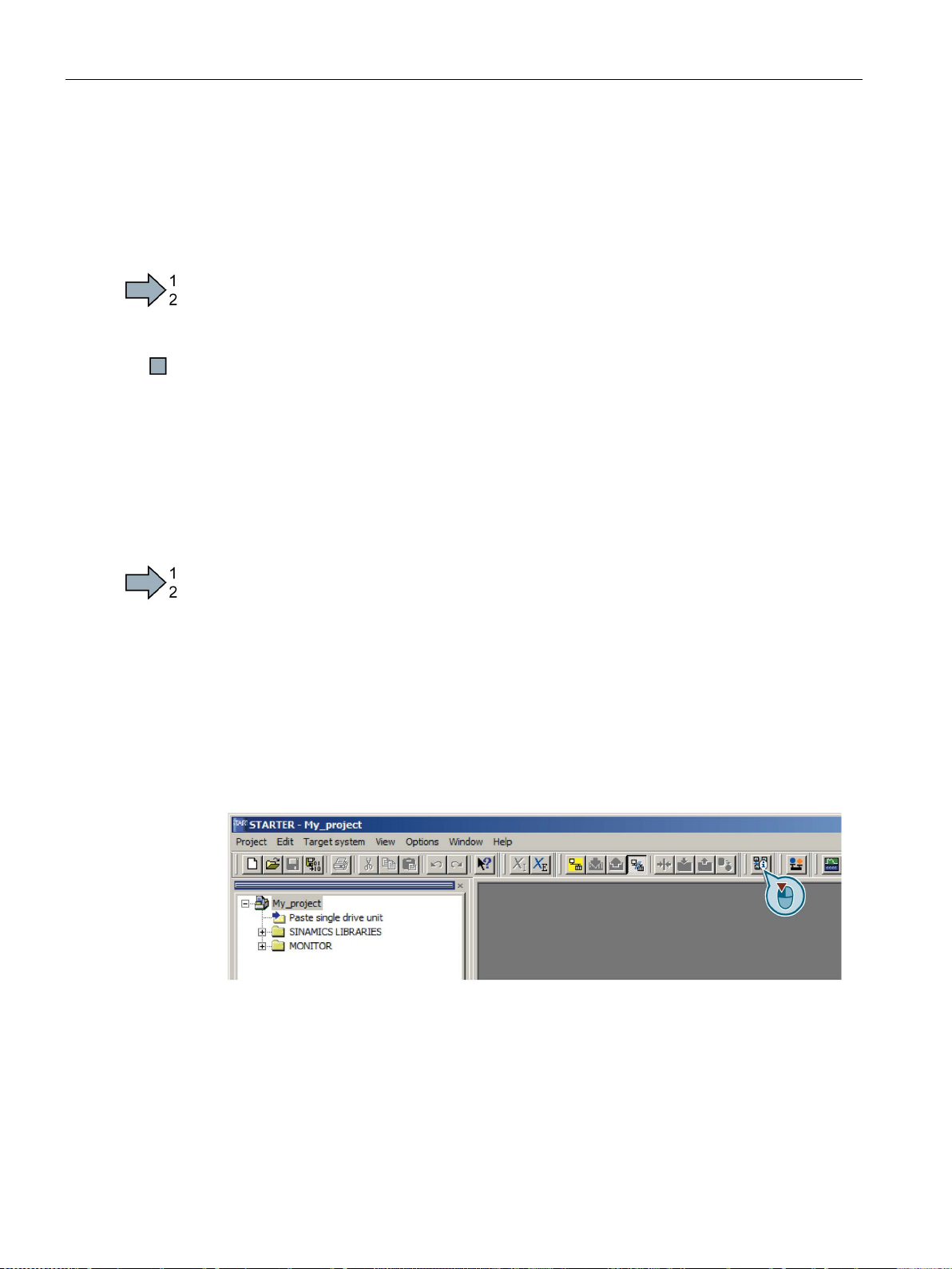
Commissioning
5.4.1
Creating a project
Creating a project
Procedure
5.4.2
Transfer inverters connected via USB into the project
Transferring inverters connected via USB to the project
Procedure
5.4 Basic commissioning with a PC
In order to create a new project, proceed as follows:
1. In the menu, select "Project" → "New…".
2. Specify a name of your choice for the project.
You have created a new project.
Proceed as follows to transfer an inverter connected via USB to your project:
1. Switch on the inverter supply voltage.
2. First insert a USB cable into your PC and then into the inverter.
3. The PC operating system installs the USB driver when you are connecting the inverter
and PC together for the first time.
– Windows 7 installs the driver automatically.
– For Windows XP you must acknowledge several system messages.
4. Start the commissioning software.
5. Select the "Accessible nodes".
Figure 5-5 "Accessible nodes" in STARTER
Converter with control units CU250D-2
70 Operating Instructions, 04/2015, FW V4.7.3, A5E34261542B AB
Page 71
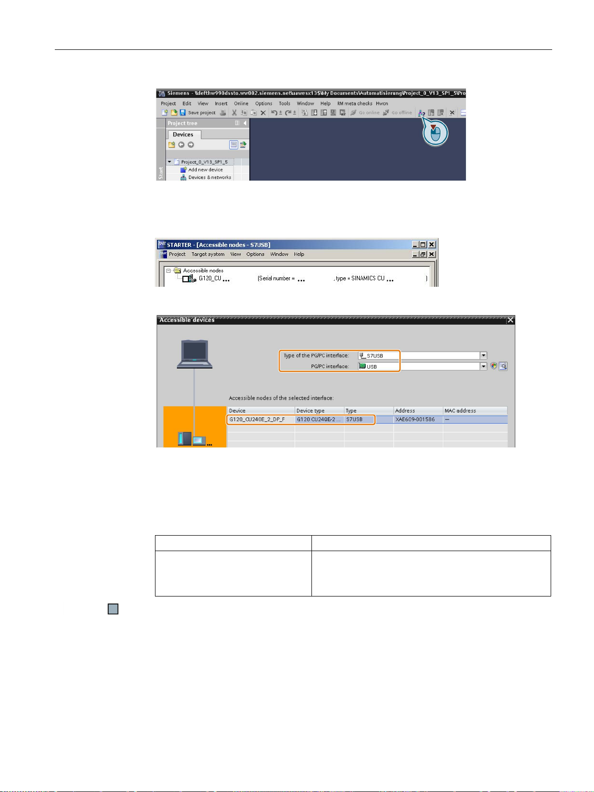
Commissioning
With STARTER
With Startdrive
5.4 Basic commissioning with a PC
Figure 5-6 "Accessible nodes" in Startdrive
6. When the USB interface is appropriately set, then the "Accessible nodes" screen form
shows the inverters that can be accessed.
Figure 5-7 Inverters found in STARTER
Figure 5-8 Inverters found in Startdrive
If you have not correctly set the USB interface, then the following "No additional nodes
found" message is displayed. In this case, follow the description below.
7. Proceed as follows:
• Select the inverter ☑.
• Press the "Accept" button.
• Accept the inverter into the project using the menu:
• "Online - Upload device as new station (hardware and
software)"
You have transferred an inverter accessible via the USB interface into your project.
Converter with control units CU250D-2
Operating Instructions, 04/2015, FW V4.7.3, A5E34261542B AB
71
Page 72
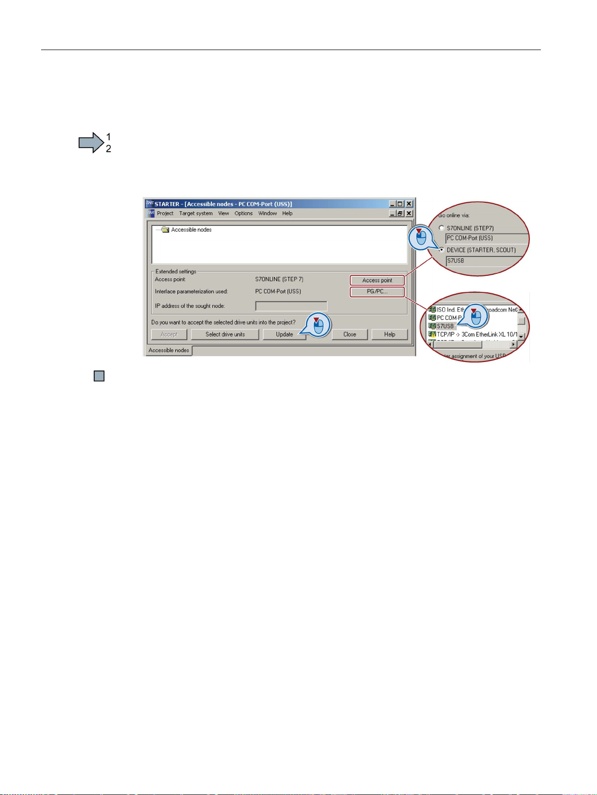
Commissioning
Setting the USB interface in STARTER
Procedure
5.4 Basic commissioning with a PC
Proceed as follows to set the USB interface in STARTER:
1. Set the "Access point" to "DEVICE (STARTER, Scout)" and the "PG/PC interface" to
"S7USB".
2. Press the "Update" button.
You have set the USB interface.
STARTER now shows the inverters connected via USB.
Converter with control units CU250D-2
72 Operating Instructions, 04/2015, FW V4.7.3, A5E34261542B AB
Page 73

Commissioning
5.4.3
Go online and start the configuration wizard
Procedure with STARTER
1.
2.
3.
oad the hardware configuration found online in
4.
5.
Procedure with Startdrive
5.4 Basic commissioning with a PC
Proceed as follows to start configuration of the inverter:
Select your project and go online: .
In the following screen form, select the inverter with
which you wish to go online.
Downl
your project (PG or PC).
Significance of the symbol in front of the inverter:
(A) The inverter is online.
(B) The inverter is offline
When you are online, double-click on "Control Unit".
Start the configuration wizards:
You have started to configure the inverter.
Proceed as follows to start configuration of the inverter:
1. Select your project and go online:
2. In the following screen form, select the inverter with which you wish to go online.
3. Once you are online, select "Commissioning" → "Commissioning Wizard":
You have started to configure the inverter.
Converter with control units CU250D-2
Operating Instructions, 04/2015, FW V4.7.3, A5E34261542B AB
73
Page 74

Commissioning
5.4.4
Carry-out basic commissioning
Procedure
1.
Select the control mode.
See also Section: Introduction, V/f control, vector control (Page 62)
2.
Select the I/O configuration
The possible configurations can be found in sections:
of the inputs and outputs
outputs (Page 52).
3.
Set the applicable motor standard and the inverter supply voltage.
Select the application for the inverter.
•
•
•
4. Select your motor.
5.
Enter the motor data according to the rating plate of your motor.
If you hav
already been entered.
6. Set the most important parameters to suit your application.
5.4 Basic commissioning with a PC
Proceed as follows to carry out basic commissioning:
"[0] Load cycle with high overload for applications requiring a high
dynamic performance, e.g. conveyor systems.
"[1] Load cycle with low overload ..." for applications that do not
require a high dynamic performance, e.g. pumps or fans.
[6], [7]: Load cycles for applications with encoderless 1FK7
synchronous motors.
e selected a motor based on its article number, the data has
to preassign the inverter interfaces.
Factory settings
(Page 51) and Default settings of inputs and
Converter with control units CU250D-2
74 Operating Instructions, 04/2015, FW V4.7.3, A5E34261542B AB
Page 75

Commissioning
7.
Technological use:
•
•
•
•
Motor identification:
•
•
•
•
Calculating the motor parameters: Select "Complete calculation".
5.4 Basic commissioning with a PC
[0]: In all applications that do not fall under [1] … [3]
[1]: Applications involving pumps and fans
[2]: Applications with short ramp-up and ramp-down times.
However, this setting is not suitable for hoisting gear and
cranes/lifting gear.
[3]: Setting only for steady-state operation with slow speed
changes. We recommend setting [1] if load surges in operation
cannot be ruled out.
[1]: Recommended setting for closed-loop speed control. After an
ON command, the inverter identifies the motor data – and with a
new ON command, optimizes the speed controller.
[2]: After an ON command, the inverter identifies the motor data at
standstill. Recommended setting for the following cases:
– You have selected "Speed control" as control mode, however
the motor cannot freely rotate, e.g. for mechanically limited
traversing sections.
– You have set "V/f control" as control mode.
[3]: This setting only makes sense after the motor identification [2].
The inverter optimizes the speed controller at the next ON
command.
[11] or [12]: The setting is the same as [1] or [2], however with the
difference that after the motor identification, the inverter
immediately changes into the "Operation" state.
Converter with control units CU250D-2
Operating Instructions, 04/2015, FW V4.7.3, A5E34261542B AB
75
Page 76

Commissioning
8.
The inverter can evaluate up to two encoders (see
er assignment
1.
2.
If you use an HTL encoder, either select one of the standard encoders
or enter the encoder data, also see section:
(Page
…R: Encoder with zero mark
If you use an SSI encoder, either select one of the standard encoders or
enter the encoder data, also se
(Page
5.4 Basic commissioning with a PC
(Page 63)):
An HTL encoder on the motor shaft.
The HTL encoder can be used for position sensing as well as for
speed measurement for the speed controller.
An encoder with an SSI interface on the load side.
You can use the SSI encoder only for position sensing.
78).
also Section: Encod-
Adapting the encoder data
78).
Converter with control units CU250D-2
76 Operating Instructions, 04/2015, FW V4.7.3, A5E34261542B AB
e section: Adapting the encoder data
Page 77
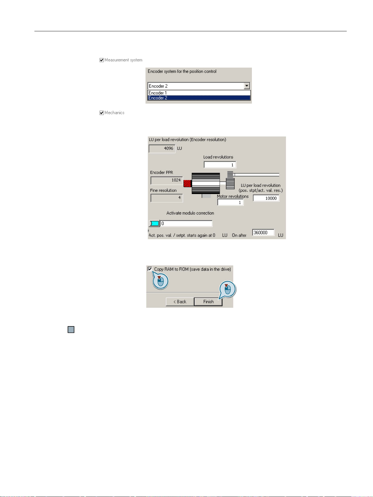
Commissioning
9.
Select the encoder that you use for position sensing.
10.
You may skip this screen initially. The settings are explained in the co
text of commissioning of the basic positioner in the section:
tioner and position control
11.
Set the check mark for "RAM to
your data in the inverter so that it is not lost when the power fails.
12.
Click "Finish" to complete the basic commissio
5.4 Basic commissioning with a PC
n-
Basic posi-
(Page 163).
You have entered all of the data that is necessary for the basic commissioning of your
inverter.
ROM (save data in the drive)" to save
ning.
Converter with control units CU250D-2
Operating Instructions, 04/2015, FW V4.7.3, A5E34261542B AB
77
Page 78

Commissioning
5.4.5
Adapting the encoder data
Preconditions
Procedure with STARTER
5.4 Basic commissioning with a PC
● You have selected an encoder type that does not precisely match your encoder, because
it is not included in the list of default encoder types.
● You have completely configured the drive.
Proceed as follows to adapt the encoder data:
1. Select the "Motor encoder" screen form.
2. Select the "Encoder data" button.
3. You have access to the following settings in the "Encoder data" screen form:
– You can change all of the encoder data.
– You can select another encoder. In this screen form, STARTER only lists the encoder
types, which are permitted for the configured interface.
If you wish to set another encoder interface, then you must reconfigure the inverter.
You have adapted the encoder data.
Converter with control units CU250D-2
78 Operating Instructions, 04/2015, FW V4.7.3, A5E34261542B AB
Page 79
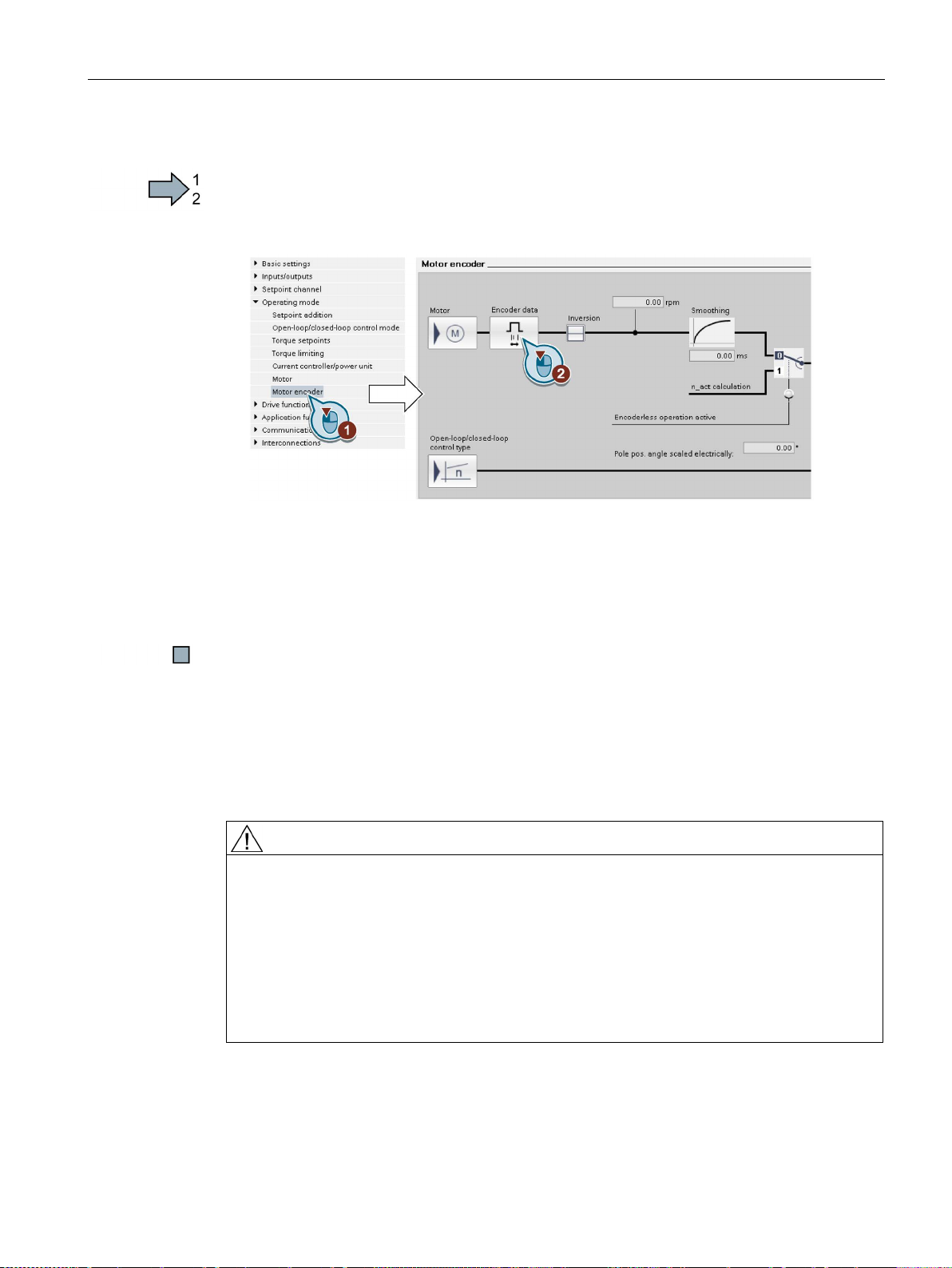
Commissioning
Procedure with Startdrive
5.4.6
Identify motor data
Identify motor data
WARNING
Danger to life from machine movements while motor data identification is in progress
5.4 Basic commissioning with a PC
Proceed as follows to adapt the encoder data:
1. Select the "Motor encoder" screen form.
2. Click the "Encoder data" button.
3. You have access to the following settings in the "Encoder data" screen form:
You have adapted the encoder data.
– You can change all of the encoder data.
– You can select another encoder type. In this screen form, STARTER only lists the
encoder types that are permitted for the configured interface.
If you wish to set another encoder interface, you must reconfigure the inverter.
The stationary measurement can turn the motor a number of revolutions. The rotating
measurement accelerates the motor up to the rated speed. Secure dangerous machine
parts before starting motor data identification:
• Before switching on, ensure that nobody is working on the machine or located within its
working area.
• Secure the machine's working area against unintended access.
• Lower suspended loads to the floor.
Converter with control units CU250D-2
Operating Instructions, 04/2015, FW V4.7.3, A5E34261542B AB
79
Page 80

Commissioning
Preconditions
Procedure with STARTER
5.4 Basic commissioning with a PC
● You selected a method of motor data identification during basic commissioning, e.g.
measurement of the motor data while the motor is stationary.
When basic commissioning is complete, the inverter issues alarm A07991.
● The motor has cooled down to the ambient temperature.
An excessively high motor temperature distorts the results of motor data identification.
To initiate motor data identification and optimize the motor control, proceed as follows:
1. Open the control panel.
Figure 5-9 Control panel
2. Assume master control for the inverter.
3. Set the "Enable signals"
4. Switch on the motor.
The inverter starts the motor data identification. This measurement can take several
minutes. After the measurement, the inverter switches off the motor.
5. Relinquish the master control after the motor data identification.
6. Press button
(RAM to ROM).
You have completed the motor data identification.
Converter with control units CU250D-2
80 Operating Instructions, 04/2015, FW V4.7.3, A5E34261542B AB
Page 81
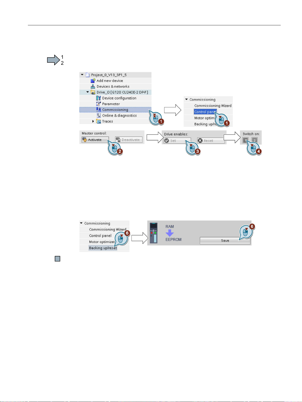
Commissioning
Procedure with Startdrive
Self-optimization of the speed control
5.4 Basic commissioning with a PC
To initiate motor data identification and optimize the motor control, proceed as follows:
1. Open the control panel.
2. Assume master control for the inverter.
3. Set the "Drive enables"
4. Switch on the motor.
The inverter starts the motor data identification. This measurement can take several
minutes. After the measurement, the inverter switches off the motor.
5. Relinquish the master control after the motor data identification.
6. Save the settings in the inverter (RAM → EEPROM):
You have completed the motor data identification.
If you have selected not only motor data identification but also rotating measurement with
self-optimization of the speed control, you must switch on the motor again as described
above and wait for the optimization run to finish.
Converter with control units CU250D-2
Operating Instructions, 04/2015, FW V4.7.3, A5E34261542B AB
81
Page 82

Commissioning
5.5
Restoring the factory setting
5.5.1
Restoring the factory setting
Restoring the factory settings when the safety functions are enabled
Settings that are not changed when restoring the factory setting
Procedure with an operator panel
5.5 Restoring the factory setting
There are cases where something goes wrong when commissioning a drive system e.g.:
● The line voltage was interrupted during commissioning and you were not able to complete
commissioning.
● You got confused during the commissioning and you can no longer understand the
individual settings that you made.
● You do not know whether the inverter was already operational.
In cases such as these, reset the inverter to the factory setting.
If you are using the integrated safety functions of the inverter, e.g. "Safe Torque Off", you
must reset the safety functions separately from the remaining inverter settings.
The settings of the safety functions are protected by a password.
The communication settings and the settings of the motor standard (IEC/NEMA) are kept
when restoring the factory setting.
Proceed as follows to restore the inverter safety functions to the factory settings:
1. p0010 = 30Set
Activate reset settings.
2. p9761 = …
Enter the password for the safety functions
3. Start the reset with p0970 = 5.
4. Wait until the inverter sets p0970 = 0.
5. Set p0971 = 1.
6. Wait until the inverter sets p0971 = 0.
7. Switch off the inverter supply voltage.
8. Wait until all LEDs on the inverter go dark.
9. Switch on the inverter supply voltage again.
You have restored the safety function settings of your inverter to the factory settings.
Converter with control units CU250D-2
82 Operating Instructions, 04/2015, FW V4.7.3, A5E34261542B AB
Page 83
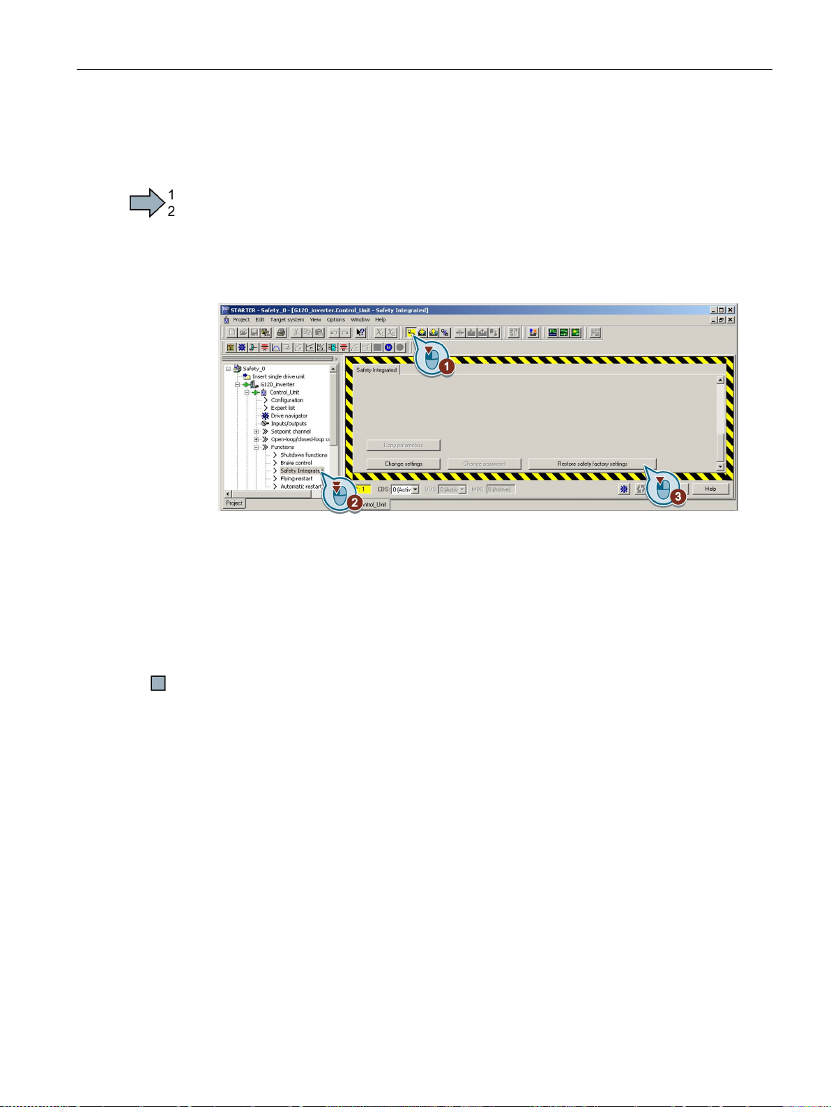
Commissioning
5.5.2
Resetting the safety functions to the factory setting
Procedure with STARTER
5.5 Restoring the factory setting
To reset the safety function settings to the factory setting without changing the standard
settings, proceed as follows:
1. Go online.
2. Open the screen form of the safety functions.
3. Select the button to restore the factory settings.
4. Enter the password,for the safety functions.
5. Confirm that the parameters have been saved (RAM to ROM).
6. Go offline.
7. Switch off the inverter supply voltage.
8. Wait until all LEDs on the inverter go dark.
9. Switch on the inverter supply voltage again.
You have restored the safety functions in the inverter to the factory settings.
Converter with control units CU250D-2
Operating Instructions, 04/2015, FW V4.7.3, A5E34261542B AB
83
Page 84
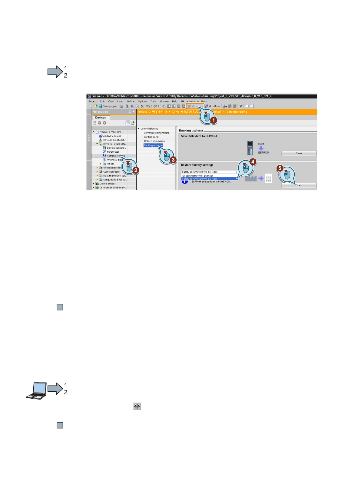
Commissioning
Procedure with Startdrive
5.5.3
Restore the settings to the factory settings (without safety functions)
Restoring the inverter to the factory setting
Procedure with STARTER
5.5 Restoring the factory setting
To reset the safety function settings to the factory setting without changing the standard
settings, proceed as follows:
1. Go online.
2. Select "Commissioning".
3. Select "Backing up/reset".
4. Select "Safety parameters are reset".
5. Click the "Start" button.
6. Enter the password,for the safety functions.
7. Confirm that the parameters have been saved (RAM to ROM).
8. Go offline.
9. Switch off the inverter supply voltage.
10.Wait until all LEDs on the inverter go dark.
11.Switch on the inverter supply voltage again.
You have restored the safety functions in the inverter to the factory settings.
Proceed as follows to reset the inverter to factory settings:
1. Go online
2. Select the button
You have reset the inverter to factory settings.
Converter with control units CU250D-2
84 Operating Instructions, 04/2015, FW V4.7.3, A5E34261542B AB
Page 85

Commissioning
Procedure with Startdrive
Procedure with operator panel
5.5 Restoring the factory setting
Proceed as follows to reset the inverter to factory settings:
1. Go online.
2. Select "Commissioning".
3. Select "Backing up/reset".
4. Select "All parameters are reset".
5. Press the "Start" button.
You have reset the inverter to factory settings.
Proceed as follows to reset the inverter to factory settings:
1. Select the "Extras" menu
2. Select the "Parameter settings" menu
3. Select the entry "Restore drive to factory settings"
You have reset the inverter to factory settings.
Converter with control units CU250D-2
Operating Instructions, 04/2015, FW V4.7.3, A5E34261542B AB
85
Page 86

Commissioning
5.5 Restoring the factory setting
Converter with control units CU250D-2
86 Operating Instructions, 04/2015, FW V4.7.3, A5E34261542B AB
Page 87

6
6.1
Fieldbus versions of the Control Unit
Fieldbus interfaces of the Control Units
Fieldbus
Profiles
S7 communi-
cation 2)
Control Unit
PROFIdrive
PROFIsafe 1)
PROFIenergy
2)
(Page 105)
CU250D-2 PN-F FO
There are different versions of the Control Units for communication with a higher-level
control system:
PROFIBUS
PROFINET
(Page 110)
EtherNet/IP
1)
Information on PROFIsafe can be found in the Safety Integrated function manual.
2)
Information about these fieldbuses, profiles and communication types can be found in the
Fieldbus Function Manual.
See also Section: Manuals for your inverter (Page 387).
2)
--- ---
✓ ✓ --- ✓ CU250D-2 DF-F
✓ ✓ ✓ ✓ CU250D-2 PN-F
CU250D-2 PN-F PP
Converter with control units CU250D-2
Operating Instructions, 04/2015, FW V4.7.3, A5E34261542B AB
87
Page 88

Adapt fieldbus configuration
6.2
PROFIdrive profile for PROFIBUS and PROFINET
6.2.1
Cyclic communication
6.2.1.1
Positioner: Cyclic communication
6.2 PROFIdrive profile for PROFIBUS and PROFINET
The send and receive telegrams of the inverter for cyclic communication are structured as
follows:
Figure 6-1 Telegrams for cyclic communication - Position control
Converter with control units CU250D-2
88 Operating Instructions, 04/2015, FW V4.7.3, A5E34261542B AB
Page 89

Adapt fieldbus configuration
Abbreviation
Explanation
STW
Control word
ZSW
Status word
(Page 100)
AKTSATZ
Currently selected traversing block
MDI_TARPOS
Position setpoint for direct setpoint input (MDI)
XIST_A
Actual position value (32 bits)
OVERRIDE
Speed setpoint
MSGW
Status word for messages
See Status word messages (Page 102)
NIST_B
Actual speed value (32 bits)
Not assigned
Freely interconnectable
MDI_VELOCITY
MDI velocity
MDI_ACC
MDI acceleration
MDI_DEC
MDI deceleration
input (MDI)
POS_STW
Control word for basic positioner
POS_ZSW
Status word for basic positioner
POS_STW1
Control word 1 for basic positioner
POS_ZSW1
Status word 1 for basic positioner
FAULT_CODE
Number of the actual fault
6.2 PROFIdrive profile for PROFIBUS and PROFINET
Table 6- 1 Explanation of the abbreviations
See Control and status word 1 (Page 91)
See Control and status word 2 (Page 93)
SATZANW Selects the traversing block See Control word block selection
MDI_MOD Selects the positioning mode in the case of direct setpoint
POS_STW2 Control word 2 for basic positioner See Control and status word 2 for the
POS_ZSW2 Status word 2 for basic positioner
WARN_CODE Number of the actual alarm
See Control word MDI mode (Page 101)
See Control and status word for the positioner (Page 94)
See Control and status word 1 for the
positioner (Page 96)
positioner (Page 98)
Converter with control units CU250D-2
Operating Instructions, 04/2015, FW V4.7.3, A5E34261542B AB
89
Page 90
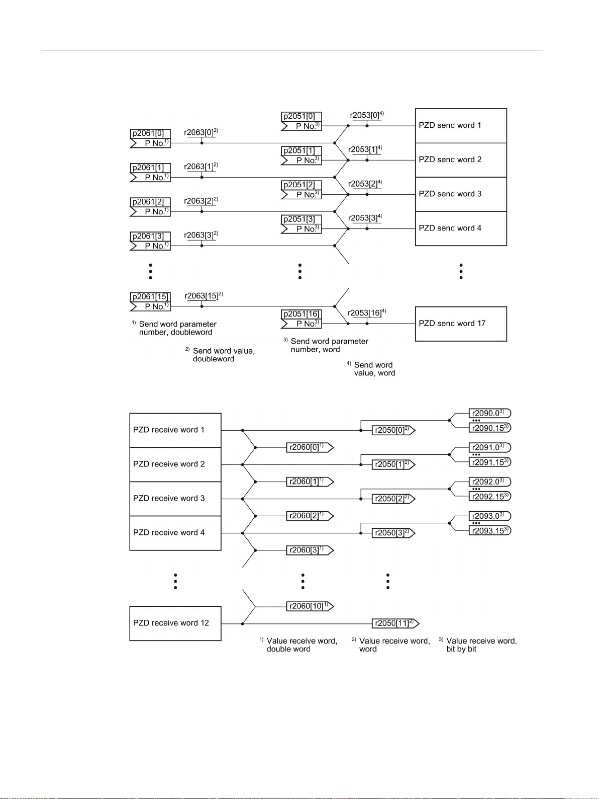
Adapt fieldbus configuration
Interconnection of the process data
6.2 PROFIdrive profile for PROFIBUS and PROFINET
Figure 6-2 Interconnection of the send words
Figure 6-3 Interconnection of the receive words
If you require an individual telegram for your application, you can adapt one of the predefined telegrams using the parameters p0922 and p2079. For details, please refer to the
List Manual, function diagrams 2420 and 2472.
Converter with control units CU250D-2
90 Operating Instructions, 04/2015, FW V4.7.3, A5E34261542B AB
Page 91

Adapt fieldbus configuration
6.2.1.2
Control and status word 1
Control word 1 (STW1)
Bit
Meaning
Comments
P No.
standstill.
still.
1 = No OFF2
It is possible to switch on the motor (ON command).
p1135 down to standstill.
1 = No quick stop (OFF3)
It is possible to switch on the motor (ON command).
0 = Inhibit operation
Immediately switch-off motor (cancel pulses).
1 = Enable operation
Switch-on motor (pulses can be enabled).
Converter rejects the actual traversing block.
1 = Do not reject traversing task
Axis can be started or travel to position setpoint.
override. Converter remains in the actual traversing block.
1 = No intermediate stop
Axis can be started or continue to travel to position setpoint.
r2090.6
active, the converter switches to "closing lockout" state.
r2090.7
r2090.7
r2090.7
0 = No control via PLC
Converter ignores the process data from the fieldbus.
the fieldbus.
0 = Stop referencing
---
1 = Start referencing
The converter does not start referencing.
12
Reserved
r2090.13
14, 15
Reserved
6.2 PROFIdrive profile for PROFIBUS and PROFINET
Table 6- 2 Control word 1 for active basic positioner
0 0 = OFF1 The motor brakes with the ramp-down time p1121 of the ramp-
function generator. The converter switches off the motor at
0 → 1 = ON The converter goes into the "ready" state. If, in addition, bit 3 =
1, the converter switches on the motor.
1 0 = OFF2 Switch off motor immediately, then the motor coasts to a stand-
2 0 = Quick stop (OFF3) Quick stop: the motor brakes with the OFF3 ramp-down time
3
4 0 = Reject traversing job Axis brakes down to standstill with the maximum deceleration.
p0840[0] =
r2090.0
p0844[0] =
r2090.1
p0848[0] =
r2090.2
p0852[0] =
r2090.3
p2641 =
r2090.4
5 0 = Intermediate stop Axis brakes down to standstill with the specified deceleration
6 0 → 1: Activate traversing job The converter starts axis travel to the setpoint position. p2631 =
0 → 1: Setpoint transfer MDI p2650 =
7 0 → 1: = Acknowledge faults Acknowledge fault in the converter. If the ON command is still
8 1 = jogging bit 0 Jogging 1 p2589 =
9 1 = jogging bit 1 Jogging 2 p2590 =
10
1 = Control via PLC Control via fieldbus, converter accepts the process data from
11
13 0 → 1: External block change The axis goes to the next traversing block. p2633 =
p2640 =
r2090.5
r2090.6
p2103[0] =
p0854[0] =
r2090.10
p2595 =
r2090.11
Converter with control units CU250D-2
Operating Instructions, 04/2015, FW V4.7.3, A5E34261542B AB
91
Page 92

Adapt fieldbus configuration
Status word 1 (ZSW1)
Bit
Meaning
Comments
P No.
Telegram 110
Telegram 111
switches on the motor.
r0899.2
r2139.3
r0899.4
r0899.5
mand and an additional ON command.
r0899.6
r2139.7
tion setpoint is within the permissible tolerance p2546.
r2684.8
the converter.
r0899.9
r2684.10
r2684.11
block active
r2684.12
r2199.0
ates
r2684.4
r2684.5
6.2 PROFIdrive profile for PROFIBUS and PROFINET
Table 6- 3 Status word 1 when the basic positioner is active
0 1 = Ready to start Power supply is switched on; electronics initialized; pulses are
inhibited.
1 1 = Ready Motor is switched on (ON command = 1); no fault is active.
With the command "Enable operation" (STW1.3) the converter
2 1 = Operation enabled Motor follows setpoint. See control word 1, bit 3. p2080[2] =
3 1 = Fault present The converter has a fault. Acknowledge fault using STW1.7. p2080[3] =
4 1 = OFF2 inactive Coast down to standstill is not active. p2080[4] =
5 1 = OFF3 inactive Quick stop is not active. p2080[5] =
6 1 = Closing lockout active It is only possible to switch on the motor after an OFF1 com-
7 1 = Alarm present Motor remains switched on; no acknowledgment necessary. p2080[7] =
8 1 = Following error in tolerance The actual difference between the actual position and the posi-
9 1 = Control requested The automation system is requested to accept the control from
10 1 = Position setpoint reached The axis has reached the position setpoint. p2080[10] =
p2080[0] =
r0899.0
p2080[1] =
r0899.1
p2080[6] =
p2080[8] =
p2080[9] =
11 1 = Reference point set The axis is referenced. p2080[11] =
12 0 → 1 = Acknowledgement, traversing
13 1 = Axis is at a standstill The absolute speed is less than p2161. p2080[13] =
14 Reserved 1 = Axis acceler-
15 Reserved 1 = Axis brakes --- p2080[15] =
Converter with control units CU250D-2
92 Operating Instructions, 04/2015, FW V4.7.3, A5E34261542B AB
--- p2080[12] =
--- p2080[14] =
Page 93

Adapt fieldbus configuration
6.2.1.3
Control and status word 2
Control word 2 (STW2)
Bit
Meaning
Comments
Interconnection
Telegram 9
Telegrams
110, 111
r2092.0
r2093.0
r2092.1
r2093.1
1 to 6
Reserved
r2092.7
r2093.7
r2092.8
r2093.8
9 to 15
Reserved
Status word 2 (ZSW2)
Bit
Meaning
Description
Interconnection
r0051.0
r0051.1
2 to 4
Reserved
---
r2139.11
r2139.12
r0896.0
r1406.8
9
Reserved
---
r0899.11
r0835.0
6.2 PROFIdrive profile for PROFIBUS and PROFINET
Table 6- 4 Control word 2 and interconnection in the converter
0 Drive data set selection DDS, bit 0 p0820[0] =
1 Drive data set selection DDS, bit 1 p0821[0] =
7 1 = Parking axis selection p0897 =
8 1 = Travel to fixed stop p1545[0] =
p0820[0] =
p0821[0] =
p0897 =
p1545[0] =
Table 6- 5 Control word 2 and interconnection in the converter
0 1 = Drive data set DDS effective, bit 0 p2081[0] =
1 1 = Drive data set DDS effective, bit 1 p2081[1] =
5 1 = Alarm class bit 0 Only for internal diagnostics when using a
SIMOTION control.
6 1 = Alarm class bit 1 p2081[6] =
7 1 = Parking axis active --- p2081[7] =
8 1 = Travel to fixed stop --- p2081[8] =
10 1 = Pulses enabled Motor switched on p2081[10] =
11 to 15 Reserved --- p2081[11] =
p2081[5] =
Converter with control units CU250D-2
Operating Instructions, 04/2015, FW V4.7.3, A5E34261542B AB
93
Page 94

Adapt fieldbus configuration
6.2.1.4
Control and status word for the positioner
Positioning control word (POS_STW)
Bit
Meaning
Comments
P No.
follow the position actual value.
r2092.0
tion actual value and setpoint.
r2092.1
r2092.2
3
4
direction.
end of the traversing range.
6…15
Reserved
---
---
6.2 PROFIdrive profile for PROFIBUS and PROFINET
Table 6- 6 POS_STW and interconnection with parameters in the inverter
0 1 = Follow-up mode The inverter continuously corrects the position setpoint to
1 1 = Set reference point The inverter accepts the reference point coordinate in its posi-
2 1 = Reference cam active The load is currently on the reference cam. p2612 =
Reserved --- ---
5 1 = Incremental jogging active If the jogging command is active, the inverter positions the
load by the specified traversing path in a positive or negative
0 = Jogging velocity active If the jogging command is active, the inverter positions the
load with the jog velocity in the direction of the beginning or
p2655[0] =
p2596 =
p2591 =
r2092.5
Converter with control units CU250D-2
94 Operating Instructions, 04/2015, FW V4.7.3, A5E34261542B AB
Page 95

Adapt fieldbus configuration
Positioning status word (POS_ZSW)
Bit
Meaning
Comments
P No.
r2683.0
changes.
r2683.2
r2684.3
1 = Axis traverses forwards
The axis traverses in the positive direction.
wards
1 = Axis traverses backwards
The axis traverses in the negative direction.
0 = Axis is stationary or traverses forwards
---
r2683.6
r2683.7
position 1
0 = Cam switching position 1 passed
position 2
0 = Cam switching position 2 passed
r2683.11
r2683.12
ing torque.
r2683.13
r2683.14
15
Reserved
---
---
6.2 PROFIdrive profile for PROFIBUS and PROFINET
Table 6- 7 POS_ZSW and interconnection with parameters in the inverter
0 1 = Follow-up mode active The inverter is in the follow-up mode. p2084[0] =
1 1 = Velocity limiting is active The inverter limits the velocity of the axis. p2084[1] =
r2683.1
2 1 = Setpoint is stationary During a positioning operation, the setpoint no longer
3 1 = Position setpoint reached The axis has reached the specified target position. p2084[3] =
p2084[2] =
4
0 = Axis is stationary or traverses back-
5
6 1 = Software limit switch, minus actuated The load is outside the permitted traversing range. p2084[6] =
7 1 = Software limit switch, plus actuated p2084[7] =
8 1 = Position actual value ≤ cam switching
9 1 = Position actual value ≤ cam switching
10 1 = Direct output 1 active The inverter sets these signals in the actual traversing
11 1 = Direct output 2 active p2084[11] =
12 1 = Fixed stop reached The axis is at the fixed stop p2084[12] =
13 1 = Fixed stop clamping torque reached The axis is at the fixed stop and has reached the clamp-
---
Feedback of the software cams in the inverter. p2084[8] =
block.
See also Section: Traversing blocks (Page 205)
p2084[4] =
r2683.4
p2084[5] =
r2683.5
r2683.8
p2084[9] =
r2683.9
p2084[10] =
r2683.10
p2084[13] =
14 1 = Travel to fixed stop active The inverter moves the axis to a fixed stop. p2084[14] =
Converter with control units CU250D-2
Operating Instructions, 04/2015, FW V4.7.3, A5E34261542B AB
95
Page 96

Adapt fieldbus configuration
6.2.1.5
Control and status word 1 for the positioner
Positioning control word 1 (POS_STW1)
Bit
Meaning
Comments
P No.
0
Traversing block selection, bit 0
p2625 = r2091.0
1
Traversing block selection, bit 1
p2626 = r2091.1
2
Traversing block selection, bit 2
p2627 = r2091.2
4 to 7
Reserved
---
---
The converter interprets the position setpoint as the
position setpoint relative to the start position.
point.
axis in the positive direction
axes in negative direction
distance
11
Reserved
---
---
immediately.
(Page 91).
13
Reserved
---
---
1 = Activate MDI
0 = Deactivate MDI
6.2 PROFIdrive profile for PROFIBUS and PROFINET
Table 6- 8 POS_STW1 and interconnection in the converter
Selecting the traversing block
3 Traversing block selection, bit 3 p2628 = r2091.3
8 0 = Relative positioning is selected
1 = Absolute positioning is selected The converter interprets the position setpoint as
9 01 = Absolute positioning for rotary
10 10 = Absolute positioning for rotary
00, 11 = Absolute positioning for a
rotary axis through the shortest
absolute position setpoint relative to machine zero
Selection of the positioning type for a rotary axis. p2651 = r2091.9
p2648 = r2091.8
p2652 = r2091.10
12 1 = Continuous acceptance The converter accepts position setpoint changes
0 = MDI block change with control
word 1, bit 6
14 1 = Select Set up Toggling the axis operating mode between "Set up"
0 = Select positioning
15
The converter accepts a changed position setpoint
with the signal change 0 → 1 of control word 1, bit
6. See also Section: Control and status word 1
and "Positioning", see also Section: Direct setpoint
input (MDI) (Page 220).
The converter receives its position setpoint from an
external control.
p2649 = r2091.12
p2653 = r2091.14
p2647 = r2091.15
Converter with control units CU250D-2
96 Operating Instructions, 04/2015, FW V4.7.3, A5E34261542B AB
Page 97

Adapt fieldbus configuration
Positioning status word 1 (POS_ZSW1)
Bit
Meaning
Comments
P No.
r2670[0]
r2670[2]
r2670[3]
r2670[4]
r2670[5]
6
7
r2684[13]
r2684[14]
r2094[0]
approach.
r2094[1]
cam.
r2684[1]
ersing block.
r2094[2]
r2094[4]
1 = MDI active
0 = MDI inactive
6.2 PROFIdrive profile for PROFIBUS and PROFINET
Table 6- 9 POS_ZSW1 and interconnection in the converter
0 Active traversing block bit 0 (20) Number of the currently selected traversing block. p2083[0] =
1 Active traversing block bit 1 (21) p2083[1] =
r2670[1]
2 Active traversing block bit 2 (22) p2083[2] =
3 Active traversing block bit 3 (23) p2083[3] =
4 Active traversing block bit 4 (24) p2083[4] =
5 Active traversing block bit 5 (25) p2083[5] =
Reserved --- ---
8 1 = STOP cam minus active The axis is currently located at a STOP cam. p2083[08] =
9 1 = STOP cam plus active p2083[09] =
10 1 = Jogging active The converter is in the jogging mode. p2083[10] =
11 1 = Reference point approach active The converter is presently executing a reference point
12 1 = Flying referencing active The converter references when passing the reference
13 1 = Traversing block active The converter receives its position setpoint from a trav-
14 1 = Set up active The axis is in the "Set up" operating mode. p2083[14] =
15
The converter receives its position setpoint from an external control.
p2083[11] =
p2083[12] =
p2083[13] =
p2083[15] =
r2670[15]
Converter with control units CU250D-2
Operating Instructions, 04/2015, FW V4.7.3, A5E34261542B AB
97
Page 98

Adapt fieldbus configuration
6.2.1.6
Control and status word 2 for the positioner
Positioning control word 2 (POS_STW2)
Bit
Meaning
Comments
P No.
follow the position actual value.
r2092.0
position actual value and setpoint.
r2092.1
r2092.2
3
4
direction.
end of the traversing range.
6
7
referencing
ence point approach
negative direction
positive direction
1 = Selects probe 2
1 = Probe falling edge
0 = Probe, rising edge
12
13
r2092.14
r2092.15
6.2 PROFIdrive profile for PROFIBUS and PROFINET
Table 6- 10 POS_STW2 and interconnection with parameters in the converter
0 1 = Activate follow-up mode The converter continuously corrects the position setpoint to
1 1 = Set reference point The converter accepts the reference point coordinate in its
2 1 = Reference cam active The axes is currently located at the reference cam. p2612 =
Reserved --- ---
5 1 = Incremental jogging active If the jogging command is active, the converter positions the
axis by the specified traversing path in a positive or negative
0 = Jogging velocity active If the jogging command is active, the converter positions the
axis with the jog velocity in the direction of the beginning or
Reserved --- ---
p2655[0] =
p2596 =
p2591 =
r2092.5
8 1 = Selects referencing using flying
0 = Selects referencing via the refer-
9 1 = Starts reference point approach in
0 = Starts reference point approach in
10
0 = Selects probe 1
11
Reserved --- ---
14 1 = Software limit switch active The converter evaluates its software limit switch. p2582 =
15 1 = STOP cams active Converter evaluates the stop cams. p2568 =
Select the referencing type. p2597 =
r2092.8
Select the start direction for automatic referencing. p2604 =
r2092.9
Edge of the probe input, with which the converter references
its actual position value.
Select the edge of the probe input, with which the converter
references its actual position value.
p2510[0] =
r2092.10
p2511[0] =
r2092.11
Converter with control units CU250D-2
98 Operating Instructions, 04/2015, FW V4.7.3, A5E34261542B AB
Page 99

Adapt fieldbus configuration
Positioning status word 2 (POS_ZSW2)
Bit
Meaning
Comments
P No.
r2683.0
changes.
r2683.2
referencing.
1 = Axis traverses forwards
The axis traverses in the positive direction.
wards
1 = Axis traverses backwards
The axis traverses in the negative direction.
0 = Axis is stationary or traverses forwards
---
r2683.6
r2683.7
position 1
0 = Cam switching position 1 passed
0 = Cam switching position 2 passed
The converter sets these signals in the actual traversing
r2683.10
r2683.11
r2683.12
ing torque.
r2683.13
r2683.14
1 = Traversing command active
0 = Axis stationary
6.2 PROFIdrive profile for PROFIBUS and PROFINET
Table 6- 11 POS_ZSW2 and interconnection with parameters in the converter
0 1 = Follow-up mode active The converter is in the follow-up mode. p2084[0] =
1 1 = Velocity limiting is active The converter limits the velocity of the axis. p2084[1] =
r2683.1
2 1 = Setpoint is stationary During a positioning operation, the setpoint no longer
p2084[2] =
3 1 = Print index outside outer window The discrepancy between the actual position and the
reference point was greater than permitted during flying
4
0 = Axis is stationary or traverses back-
5
6 1 = Software limit switch, minus actuated The axis is outside the permitted traversing range. p2084[6] =
7 1 = Software limit switch, plus actuated p2084[7] =
8 1 = Position actual value ≤ cam switching
9 1 = Position actual value ≤ cam switching
position 2
10 1 = Direct output 1 active
11 1 = Direct output 2 active p2084[11] =
12 1 = Fixed stop reached The axis is at the fixed stop p2084[12] =
---
Feedback of the cam sequencer in the converter. p2084[8] =
block.
See also paragraph: Traversing blocks (Page 205)
p2084[3] =
r2684.3
p2084[4] =
r2683.4
p2084[5] =
r2683.5
r2683.8
p2084[9] =
r2683.9
p2084[10] =
13 1 = Fixed stop clamping torque reached The axis is at the fixed stop and has reached the clamp-
14 1 = Travel to fixed stop active The converter moves the axis to a fixed stop. p2084[14] =
15
Converter with control units CU250D-2
Operating Instructions, 04/2015, FW V4.7.3, A5E34261542B AB
Feedback signal indicating as to whether the converter
is currently moving the axis.
p2084[13] =
p2084[15] =
r2684.15
99
Page 100
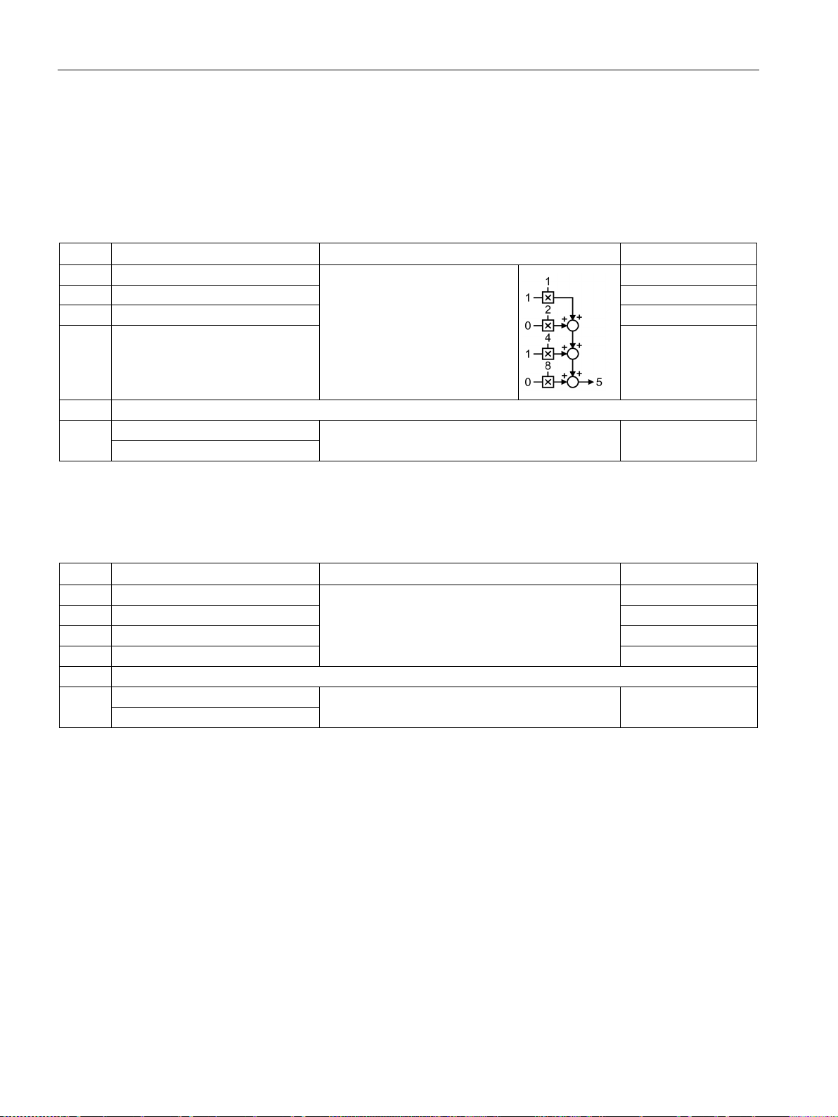
Adapt fieldbus configuration
6.2.1.7
Control word block selection
Block selection
Bit
Meaning
Comments
P No.
0
Block selection, bit 0
p2625 = r2091.0
1
Block selection, bit 1
p2626 = r2091.1
2
Block selection, bit 2
p2627 = r2091.2
4…14
Reserved
0 = Deactivate MDI
1 = Activate MDI
Actual traversing block
Bit
Meaning
Comments
P No.
0
Actual traversing block, bit 0
p2081[0] = r2670.0
1
Actual traversing block, bit 1
p2081[1] = r2670.1
2
Actual traversing block, bit 2
p2081[2] = r2670.2
3
Actual traversing block, bit 3
p2081[3] = r2670.3
4…14
Reserved
0 = MDI active
1 = MDI not active
6.2 PROFIdrive profile for PROFIBUS and PROFINET
Table 6- 12 Block selection and interconnection in the converter
Example for selecting traversing
block number 5:
3 Block selection, bit 3 p2628 = r2091.3
15
Switching from traversing blocks to direct setpoint
input.
p2647 = r2091.15
Table 6- 13 Feedback signal of the actual traversing block
---
15
--- p2081[15] = r2670.15
Converter with control units CU250D-2
100 Operating Instructions, 04/2015, FW V4.7.3, A5E34261542B AB
 Loading...