

Siemens SINAMICS G120,CU240B-2,CU240E-2 Compact Operating Instructions
CU240B-2 and CU240E-2 Control
U
nits
___________________
___________________
___________________
___________________
___________________
SINAMICS
SINAMICS G120
CU240B-2 and CU240E-2 Control
U
nits
Compact Operating Instructions
Edition 04/2015
04/2015
A5E35792002B AA
Fundamental safety
instructions
1
Scope of delivery
2
Installing
3
Commissioning
4
More information
5
Scan the QR code
for additional
information about
SINAMICS G120.
Siemens AG
Division Digital Factory
Postfach 48 48
90026 NÜRNBERG
GERMANY
A5E35792002B AA
Ⓟ
04/2015 Subject to change
Copyright © Siemens AG 2015.
All rights reserved
Legal information
Warning notice system
This manual contains notices you have to observe in order to ensure your personal safety, as well as to prevent
damage to property. The notices referring to your personal safety are highlighted in the manual by a safety alert
symbol, notices referring only to property damage have no safety alert symbol. These notices shown below are
graded according to the degree of danger.
DANGER
indicates that death or severe personal injury will result if proper precautions are not taken.
WARNING
indicates that death or severe personal injury may result if proper precautions are not taken.
CAUTION
indicates that minor personal injury can result if proper precautions are not taken.
NOTICE
indicates that property damage can result if proper precautions are not taken.
If more than one degree of danger is present, the warning notice representing the highest degree of danger will
be used. A notice warning of injury to persons with a safety alert symbol may also include a warning relating to
property damage.
Qualified Personnel
The product/system described in this documentation may be operated only by
personnel qualified
for the specific
task in accordance with the relevant documentation, in particular its warning notices and safety instructions.
Qualified personnel are those who, based on their training and experience, are capable of identifying risks and
avoiding potential hazards when working with these products/systems.
Proper use of Siemens products
Note the following:
WARNING
Siemens products may only be used for the applications described in the catalog and in the relevant technical
documentation. If products and components from other manufacturers are used, these must be recommended
or approved by Siemens. Proper transport, storage, installation, assembly, commissioning, operation and
maintenance are required to ensure that the products operate safely and without any problems. The permissible
ambient conditions must be complied with. The information in the relevant documentation must be observed.
Trademarks
All names identified by ® are registered trademarks of Siemens AG. The remaining trademarks in this publication
may be trademarks whose use by third parties for their own purposes could violate the rights of the owner.
Disclaimer of Liability
We have reviewed the contents of this publication to ensure consistency with the hardware and software
described. Since variance cannot be precluded entirely, we cannot guarantee full consistency. However, the
information in this publication is reviewed regularly and any necessary corrections are included in subsequent
editions.

CU240B-2 and CU240E-2 Control Units
Compact Operating Instructions, 04/2015, A5E35792002B AA
3
Table of contents
1 Fundamental safety instructions .............................................................................................................. 4
1.1 General safety instructions ....................................................................................................... 4
1.2 Industrial security ...................................................................................................................... 5
2 Scope of delivery .................................................................................................................................... 6
3 Installing ................................................................................................................................................. 7
3.1 Plugging the Control Unit onto the Power Module .................................................................... 7
3.2 Overview of the interfaces ........................................................................................................ 8
3.3 Terminal strips on CU240B-2 Control Units............................................................................ 10
3.4 Terminal strips on CU240E-2 Control Units............................................................................ 13
4 Commissioning ..................................................................................................................................... 18
4.1 Tools to commission the converter ......................................................................................... 18
4.2 Commissioning with BOP-2 operator panel ............................................................................ 19
4.2.1 Basic commissioning with BOP-2 ........................................................................................... 19
4.2.2 Standard Drive Control ........................................................................................................... 21
4.2.3 Dynamic Drive Control ............................................................................................................ 23
4.3 Connecting the inverter to the fieldbus ................................................................................... 26
4.4 Frequently required parameters ............................................................................................. 28
5 More information ................................................................................................................................... 31
5.1 Manuals for your inverter ........................................................................................................ 31
5.2 Product support ....................................................................................................................... 32
This manual describes how you install the CU240B-2 or CU240E-2 Control Unit of the
SINAMICS G120 inverter and commission it.
What is the meaning of the symbols in the manual?
An operating instruction starts here.
This concludes the operating instruction.
CU240B-2 and CU240E-2 Control Units
4 Compact Operating Instructions, 04/2015, A5E35792002B AA
1
1.1
General safety instructions
WARNING
Risk of death if the safety instructions and remaining risks are not carefully observed
If the safety instructions and residual risks are not observed in the associated hardware
documentation, accidents involving severe injuries or death can occur.
• Observe the safety instructions given in the hardware documentation.
• Consider the residual risks for the risk evaluation.
WARNING
Danger to life or malfunctions of the machine as a result of incorrect or changed
parameterization
As a result of incorrect or changed parameterization, machines can malfunction, which in
turn can lead to injuries or death.
• Protect the parameterization (parameter assignments) against unauthorized access.
• Respond to possible malfunctions by applying suitable measures (e.g. EMERGENCY
STOP or EMERGENCY OFF).
Fundamental safety instructions
1.2 Industrial security
CU240B-2 and CU240E-2 Control Units
Compact Operating Instructions, 04/2015, A5E35792002B AA
5
1.2
Industrial security
Note
Industrial security
Siemens provides products and solutions with industrial security functi
ons that support the
secure operation of plants, solutions, machines, equipment and/or networks. They are
important components in a holistic industrial security concept. With this in mind, Siemens’
products and solutions undergo continuous development. Sie
mens recommends strongly
that you regularly check for product updates.
For the secure operation of Siemens products and solutions, it is necessary to take suitable
preventive action (e.g. cell protection concept) and integrate each component into a holisti
c,
state
-of-the-art industrial security concept. Third-party products that may be in use should
also be considered. For more information about industrial security, visit Hotspot
-Text
(
http://www.siemens.com/industrialsecurity).
To stay informed about product updates as they occur, sign up for a product
-specific
newsletter. For more information, visit Hotspot
-Text
(
http://support.automation.siemens.com).
WARNING
Danger as a result of unsafe operating states resulting from software manipulation
Software manipulation (e.g. by viruses, Trojan horses, malware, worms) can cause unsafe
operating states to develop in your installation which can result in death, severe injuries
and/or material damage.
• Keep the software up to date.
You will find relevant information and newsletters at this address
(http://support.automation.siemens.com).
• Incorporate the automation and drive components into a holistic, state-of-the-art
industrial security concept for the installation or machine.
You will find further information at this address
(http://www.siemens.com/industrialsecurity).
• Make sure that you include all installed products into the holistic industrial security
concept.
CU240B-2 and CU240E-2 Control Units
6 Compact Operating Instructions, 04/2015, A5E35792002B AA
2
Scope of delivery
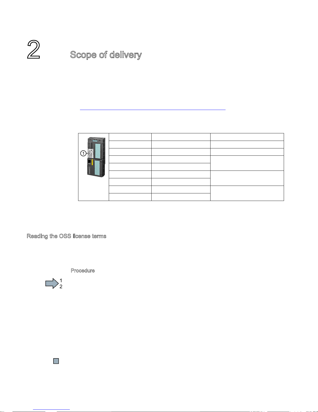
The delivery comprises at least the following components:
● A CU240B-2 or a CU240E-2 control unit with firmware, which is ready to run. Options for
upgrading and downgrading the firmware can be found on the Internet: Firmware
(http://support.automation.siemens.com/WW/news/en/67364620).
The fieldbus interface of the Control Unit depends on the Article No. The Article No., the
designation and the version of the hardware (e.g. 02) and firmware (e.g. 4.6) can be
found on the rating plate
① of the Control Unit.
Designation Article number Fieldbus
CU240B-2 6SL3244-0BB00-1BA1 USS, Modbus RTU
CU240B-2 DP 6SL3244-0BB00-1PA1 PROFIBUS DP
CU240E-2 6SL3244-0BB12-1BA1 USS, Modbus RTU
CU240E-2 F 6SL3244-0BB13-1BA1
CU240E-2 DP 6SL3244-0BB12-1PA1 PROFIBUS DP
CU240E-2 DP-F 6SL3244-0BB13-1PA1
CU240E-2 PN 6SL3244-0BB12-1FA0 PROFINET IO, EtherNet/IP
CU240E-2 PN-F 6SL3244-0BB13-1FA0
● Compact Operating Instructions in German and English
● The inverter contains open-source software (OSS). The OSS license terms are saved in
the inverter.
Reading the OSS license terms
The inverter contains open-source software (OSS). OSS comprises open source text and
satisfies special license terms. If you wish to read the license terms, you must transfer them
from the inverter to a PC.
P
rocedure
To transfer the OSS license terms from the inverter to a PC, proceed as follows:
1. S
witch off the inverter power supply.
2. Insert an empty memory card into the card slot of the inverter. See also Section:
Overview of the interfaces (Page 8)
3. Switch on the inverter power supply.
4. When you have switched on the power supply, wait 30 seconds.
During this time, the inverter writes the "Read_OSS.ZIP" file onto the memory card.
5. Switch off the inverter
power supply.
6. Withdraw the memory card from the inverter.
7. Use a card reader and load the file to a PC.
You have then transferred the OSS license terms from the inverter to a PC, and you can now
read the license terms.
CU240B-2 and CU240E-2 Control Units
Compact Operating Instructions, 04/2015, A5E35792002B AA
7
3
3.1
Plugging the Control Unit onto the Power Module
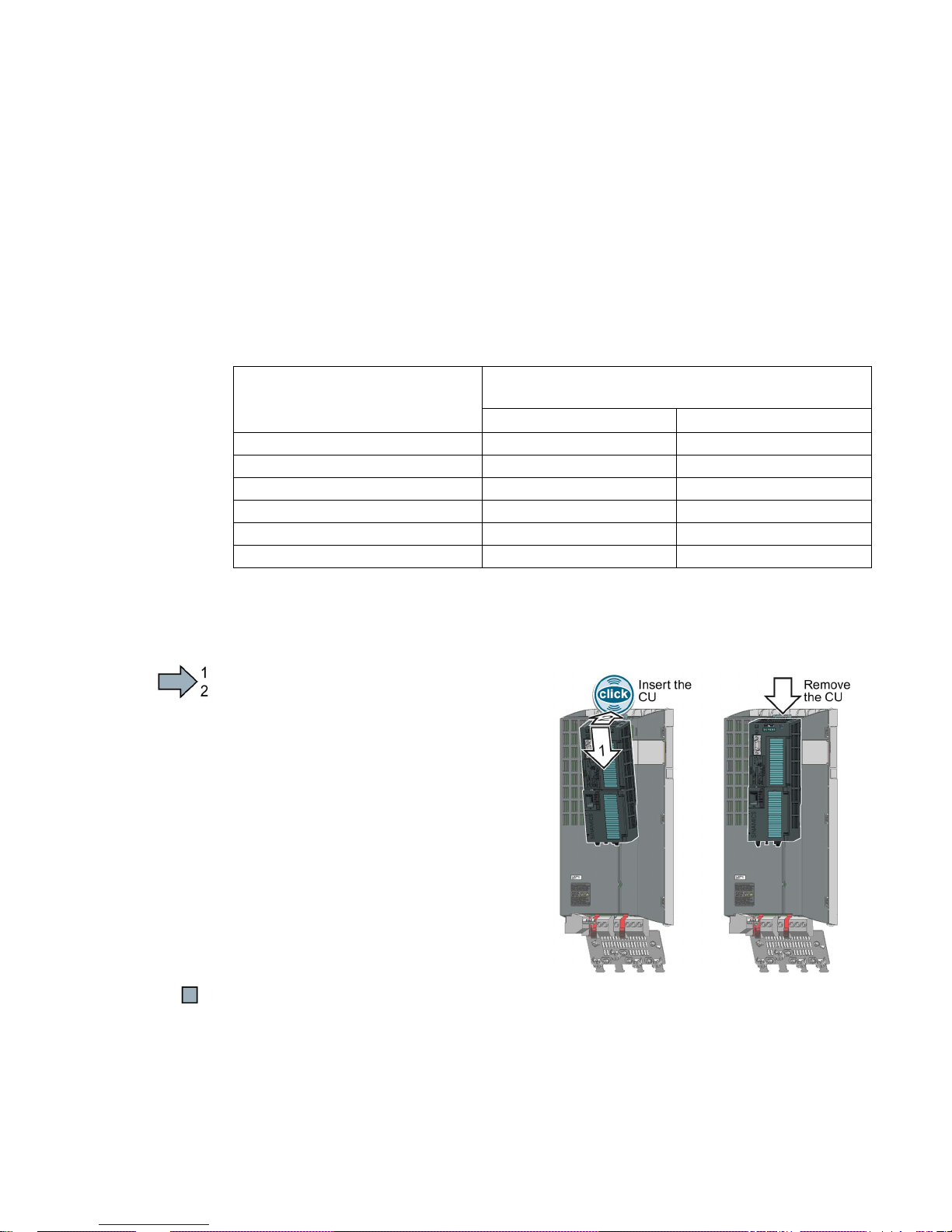
Permissible Power Modules
You may operate the Control Unit with the following Power Modules:
Power Module
✓ = operation with Power Module permissible,
--- = not permissible
CU240B-2
CU240E-2
PM340 1AC
---
✓
PM230 IP20 and push-through ✓ ✓
PM240
✓
✓
PM240-2 ✓ ✓
PM250
✓ ✓ PM260
✓
✓
Plugging the Control Unit onto an IP20 Power Module FSA … FSF
Procedure
Proceed as follows to plug the Control Unit
onto a Power Module:
1.
Locate the lugs at the rear of the Control
Unit in the matching recesses of the
Power Module.
2.
Press the Control Unit onto the Power
Module until you hear it latch into place.
You have now plugged the Control Unit onto the Power Module.
To remove the Control Unit, press on the release button on the Power Module and withdraw
the Control Unit.
Installing
3.2 Overview of the interfaces
CU240B-2 and CU240E-2 Control Units
8 Compact Operating Instructions, 04/2015, A5E35792002B AA
3.2
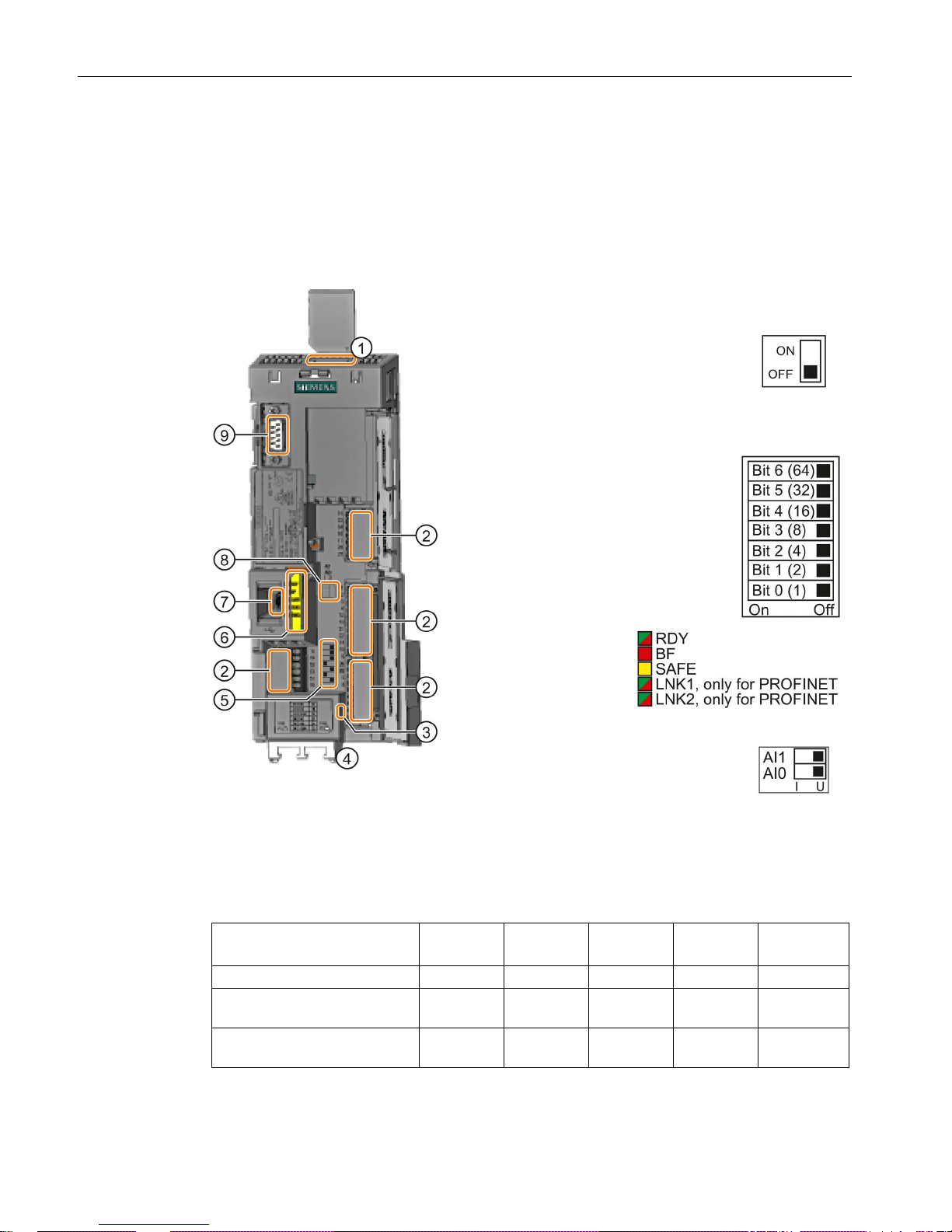
Overview of the interfaces
Interfaces at the front of the Control Unit
To access the interfaces at the front of the Control Unit, you must lift the Operator Panel (if
one is being used) and open the front doors.
①
Memory card slot
②
Terminal strips
③
Depending on the fieldbus:
•
USS, Modbus: Bus termination
•
PROFIBUS, PROFINET,
EtherNet/IP: No function
④
Fieldbus inter
faces at the lower side
⑤
Selecting the fieldbus address
On all Control Units with the e
x-
ception of CU240E
-2 PN and
CU240E
-2 PN-F.
⑥
Status LED
⑦
USB interface for connection to a PC
⑧
Switch for AI
0 and AI 1
1)
(U/I)
•
I 0/4 mA … 20 mA
•
U -10/0 V … 10 V
1)
AI 1 is not available on the CU240B-2
⑨
Connection to the operator panel
Table 3- 1 Number of inputs and outputs
Digital
inputs DI
Digital
outputs DO
Analog
inputs AI
Analog
outputs AO
Safe inputs
F-DI
1)
CU240B-2, CU240B-2 DP
4 1 1 1 0
CU240E-2, CU240E-2 DP,
CU240E-2 PN
6 3 2 2 1
CU240E-2 F, CU240E-2 DP-F,
CU240E-2 PN-F
6 3 2 2 3
1)
Every F-DI safe input used occupies two digital inputs DI
Installing
3.2 Overview of the interfaces
CU240B-2 and CU240E-2 Control Units
Compact Operating Instructions, 04/2015, A5E35792002B AA
9
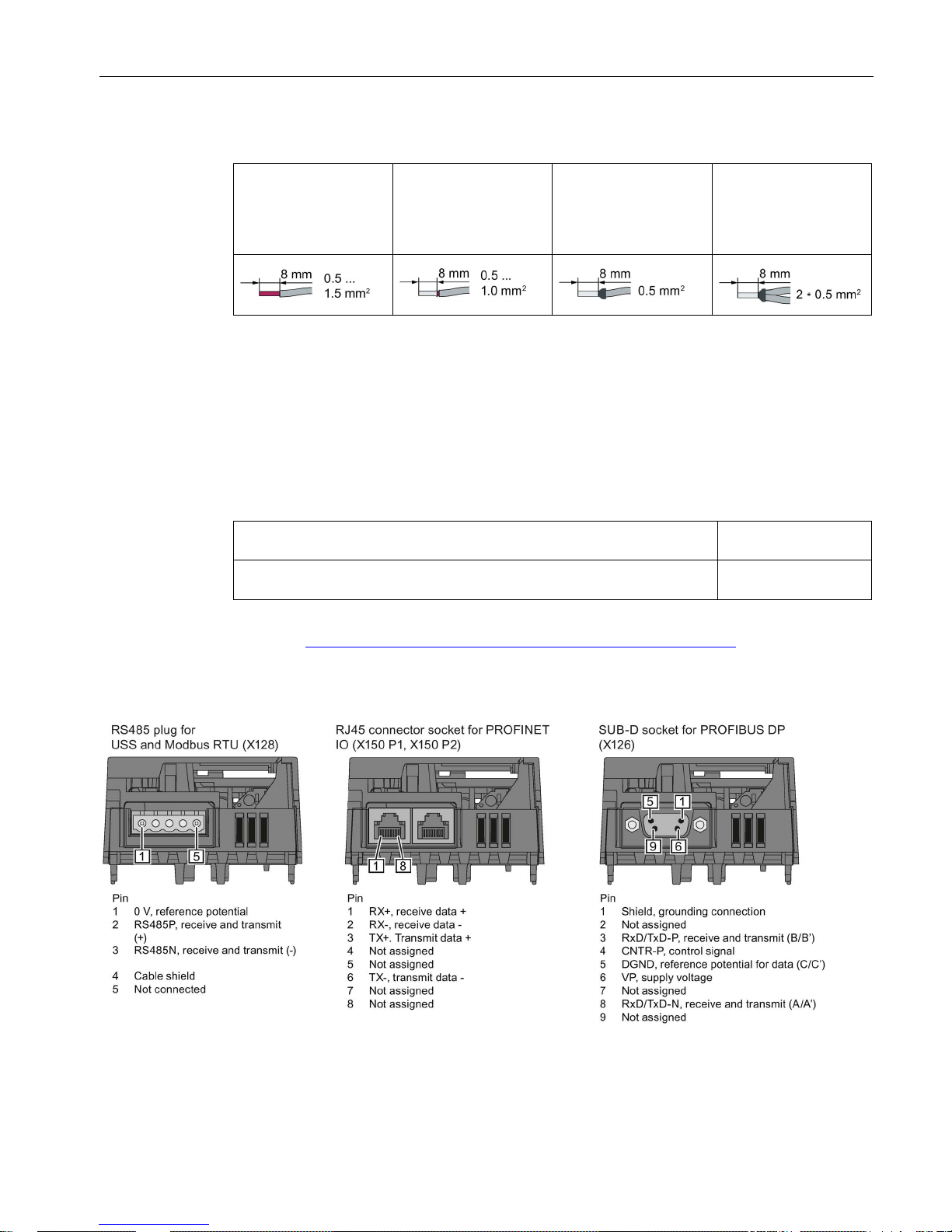
Table 3- 2 Permissible cable and wiring options
Solid or flexible conduc-
tors
Finely stranded con-
ductor with non-
insulated end sleeve
Finely stranded con-
ductor with partially
insulated end sleeve
Two finely stranded
conductors with the
same cross-section
with partially insulated
twin end sleeves
Wiring the terminal strip in compliance with EMC
● If you use shielded cables, then you must connect the shield to the mounting plate of the
control cabinet or with the shield support of the inverter through a good electrical
connection and a large surface area.
● Use the shield connection plate of the Control Unit as shield support and strain relief.
Table 3- 3 Article numbers
Shield connection kit 2 for the CU240B-2 and CU240E-2 Control Units with
all fieldbus interfaces except for PROFINET.
6SL3264-1EA00-0HA0
Shield connection kit 3 for the CU230P-2 and CU240E-2 Control Units with
PROFINET interface
6SL3264-1EA00-0HB0
Further information about EMC-compliant wiring is available on the Internet: EMC installation
guideline (http://support.automation.siemens.com/WW/view/en/60612658)
Interfaces at the lower side of the CU240B-2 and CU240E-2 Control Units
Installing
3.3 Terminal strips on CU240B-2 Control Units
CU240B-2 and CU240E-2 Control Units
10 Compact Operating Instructions, 04/2015, A5E35792002B AA
3.3
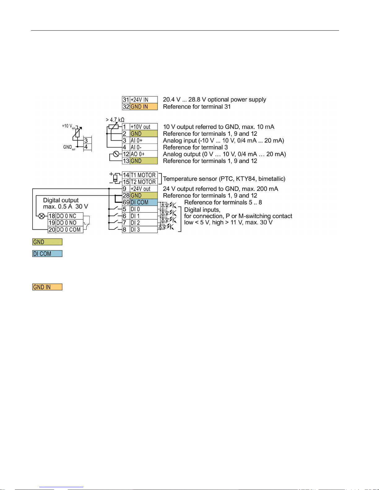
Terminal strips on CU240B-2 Control Units
Terminal strips with wiring example
All terminals labelled with reference potential "GND" are connected internally in the inverter.
Reference potential "DI COM" is electrically isolated from "GND".
→ If, as shown above, the 24 V supply from terminal 9 is used to supply the digital inputs, then you
must connect "GND" to "DI COM".
Terminals 31, 32
Reference potential "GND IN" is electrically isolated from "GND". When an optional 24 V power supply
is connected at terminals 31, 32, even when the Power Module is disconnected from the line supply,
the Control Unit remains in operation. The Control Unit thus maintains the fieldbus communication, for
example.
→ at terminals 31, 32, only connect a power supply that is in accordance with SELV (Safety Extra Low
Voltage) or PELV (Protective Extra Low Voltage).
→ if you use a common external power supply for terminals 31, 32 and the digital inputs, you must
connect "GND" to "GND IN".
Terminals 3, 4: You may use the internal 10V power supply or an external power supply for the analog input.
→ If you use the internal 10 V power supply, you must connect AI 0- to GND.
Figure 3-1 Wiring example of the digital inputs with the internal inverter 24 V power supply
 Loading...