

Siemens SINAMICS G110D Operating Instructions Manual


SINAMICS G110D
___________________
___________________
___________________
___________________
___________________
___________________
___________________
___________________
___________________
___________________
SINAMICS
SINAMICS G110D
Distributed Converter SINAMICS
G110D
Operating Instructions
Edition 07/2016, Firmware version 3.63
07/2016, FW V3.63
A5E36768472B AB
Fundamental safety
instructions
1
Introduction
2
Description
3
Connection
4
Commissioning
5
Functions
6
Service and maintenance
7
Messages and fault codes
8
Technical data
9
Appendix A
A

Siemens AG
Division Digital Factory
Postfach 48 48
90026 NÜRNBERG
GERMANY
Document order number: (null)
Ⓟ
Copyright © Siemens AG 2013 - 2016.
All rights reserved
Legal information
Warning notice system
DANGER
indicates that death or severe personal injury will result if proper precautions are not taken.
WARNING
indicates that death or severe personal injury may result if proper precautions are not taken.
CAUTION
indicates that minor personal injury can result if proper precautions are not taken.
NOTICE
indicates that property damage can result if proper precautions are not taken.
Qualified Personnel
personnel qualified
Proper use of Siemens products
WARNING
Siemens products may only be used for the applications described in the catalog and in the relevant technical
maintenance are required to ensure that the products operate safely and without any problems. The permissible
ambient conditions must be complied with. The information in the relevant documentation must be observed.
Trademarks
Disclaimer of Liability
This manual contains notices you have to observe in order to ensure your personal safety, as well as to prevent
damage to property. The notices referring to your personal safety are highlighted in the manual by a safety alert
symbol, notices referring only to property damage have no safety alert symbol. These notices shown below are
graded according to the degree of danger.
If more than one degree of danger is present, the warning notice representing the highest degree of danger will
be used. A notice warning of injury to persons with a safety alert symbol may also include a warning relating to
property damage.
The product/system described in this documentation may be operated only by
task in accordance with the relevant documentation, in particular its warning notices and safety instructions.
Qualified personnel are those who, based on their training and experience, are capable of identifying risks and
avoiding potential hazards when working with these products/systems.
Note the following:
documentation. If products and components from other manufacturers are used, these must be recommended
or approved by Siemens. Proper transport, storage, installation, assembly, commissioning, operation and
All names identified by ® are registered trademarks of Siemens AG. The remaining trademarks in this publication
may be trademarks whose use by third parties for their own purposes could violate the rights of the owner.
We have reviewed the contents of this publication to ensure consistency with the hardware and software
described. Since variance cannot be precluded entirely, we cannot guarantee full consistency. However, the
information in this publication is reviewed regularly and any necessary corrections are included in subsequent
editions.
for the specific
06/2016 Subject to change

Table of contents
1 Fundamental safety instructions .............................................................................................................. 9
2 Introduction ........................................................................................................................................... 17
3 Description ............................................................................................................................................ 29
4 Connection ........................................................................................................................................... 35
5 Commissioning ..................................................................................................................................... 61
1.1 General safety instructions ....................................................................................................... 9
1.2 Safety instructions for electromagnetic fields (EMF) .............................................................. 13
1.3 Handling electrostatic sensitive devices (ESD) ...................................................................... 13
1.4 Industrial security .................................................................................................................... 14
1.5 Residual risks of power drive systems .................................................................................... 15
2.1 About this manual ................................................................................................................... 17
2.2 Adapting the Inverter to the application .................................................................................. 19
2.2.1 General basics ........................................................................................................................ 19
2.2.2 Parameter ............................................................................................................................... 20
2.2.3 Parameters with follow-on parameterization .......................................................................... 21
2.2.4 Frequently required parameters ............................................................................................. 21
2.3 Extended adaptation of parameters ........................................................................................ 23
2.3.1 BICO technology: basic principles .......................................................................................... 23
2.3.2 BICO technology: example ..................................................................................................... 26
3.1 Overview of SINAMICS G110D Inverters ............................................................................... 29
3.2 Components of the Inverter system ........................................................................................ 30
4.1 Procedure for installing the Inverter ........................................................................................ 35
4.2 General layout of SINAMICS G110D ...................................................................................... 36
4.3 Removal of CU area cover and braking resistor connection hatch ........................................ 37
4.4 Drill pattern for the SINAMICS G110D ................................................................................... 38
4.5 Mounting orientation ............................................................................................................... 39
4.6 Ambient operating conditions ................................................................................................. 40
4.7 SINAMICS G110D Specifications ........................................................................................... 42
4.8 Cables and connections ......................................................................................................... 47
4.9 Configuring the AS-i slave ...................................................................................................... 53
4.10 Using the AS-i Programmer .................................................................................................... 58
5.1 Typical commissioning scenarios ........................................................................................... 61
5.2 Restoring the factory settings ................................................................................................. 63
SINAMICS G110D
Operating Instructions, 07/2016, FW V3.63, A5E36768472B AB
5

Table of contents
6 Functions .............................................................................................................................................. 91
5.3 Preparing for commissioning ................................................................................................. 64
5.4 Prerequisites of using the factory settings ............................................................................. 66
5.5 Factory settings for the Inverter ............................................................................................. 67
5.6 Commissioning with STARTER ............................................................................................. 69
5.7 Basic commissioning with IOP ............................................................................................... 80
5.8 Example application ............................................................................................................... 82
5.9 Backup data and storage ....................................................................................................... 86
5.9.1 Saving and transferring data using the IOP ........................................................................... 86
5.9.2 Saving and transferring data using the SD memory card ...................................................... 88
6.1 Overview of Inverter functions ............................................................................................... 91
6.2 Inverter Control ...................................................................................................................... 94
6.2.1 Frequency inverter control using digital inputs (two/three-wire control) ................................ 94
6.2.2 Two-wire control, method 1 .................................................................................................... 97
6.2.3 Two-wire control, method 2 .................................................................................................... 98
6.2.4 Two-wire control, method 3 .................................................................................................... 99
6.2.5 Three-wire control, method 1 ............................................................................................... 100
6.2.6 Three-wire control, method 2 ............................................................................................... 101
6.3 Command sources ............................................................................................................... 102
6.3.1 Selecting command sources ................................................................................................ 102
6.3.2 Assigning functions to digital inputs ..................................................................................... 103
6.3.3 Controlling the motor using the fieldbus .............................................................................. 104
6.4 Setpoint sources .................................................................................................................. 105
6.4.1 Selecting the setpoint source [P1000] ................................................................................. 105
6.4.2 Frequency setpoint using analog input [P1000=2] .............................................................. 106
6.4.3 Using a motorized potentiometer as a setpoint source........................................................ 107
6.4.4 Using fixed frequencies as a setpoint source ...................................................................... 108
6.4.5 Running the motor in jog mode (JOG function) ................................................................... 109
6.4.6 Specifying the motor speed via the fieldbus ........................................................................ 110
6.5 Changing over the command data sets (manual, automatic) .............................................. 111
6.6 Setpoint preparation ............................................................................................................. 114
6.6.1 Overview of setpoint preparation ......................................................................................... 114
6.6.2 Minimum frequency and maximum frequency ..................................................................... 115
6.6.3 Parameterizing the ramp-function generator ....................................................................... 116
6.7 Motor control ........................................................................................................................ 118
6.7.1 V/f control with linear characteristics.................................................................................... 118
6.7.2 V/f control with parabolic characteristic ............................................................................... 120
6.7.3 Typical applications for V/f control ....................................................................................... 120
6.7.4 Additional characteristics of the V/f control .......................................................................... 121
6.8 Protection functions ............................................................................................................. 122
6.8.1 Protective functions of the frequency inverter ...................................................................... 122
6.8.2 Overtemperature protection for the Inverter ........................................................................ 123
6.8.3 Overcurrent protection ......................................................................................................... 126
6.8.4 Limiting the maximum DC link voltage ................................................................................. 127
6.8.5 Load torque monitoring (system protection) ........................................................................ 128
SINAMICS G110D
6 Operating Instructions, 07/2016, FW V3.63, A5E36768472B AB

Table of contents
7 Service and maintenance .................................................................................................................... 197
8 Messages and fault codes ................................................................................................................... 205
9 Technical data .................................................................................................................................... 209
A Appendix A ......................................................................................................................................... 213
Index................................................................................................................................................... 219
6.9 Technological functions ........................................................................................................ 130
6.9.1 Technological functions ........................................................................................................ 130
6.9.2 Braking functions .................................................................................................................. 130
6.9.2.1 Braking functions of the Inverter ........................................................................................... 130
6.9.2.2 DC braking ............................................................................................................................ 132
6.9.2.3 Dynamic braking ................................................................................................................... 135
6.9.2.4 Parameterizing a motor holding brake .................................................................................. 137
6.9.3 Automatic restart and flying restart ....................................................................................... 141
6.9.3.1 Automatic restart ................................................................................................................... 141
6.9.3.2 Flying restart ......................................................................................................................... 146
6.9.4 PID technology controller ...................................................................................................... 149
6.9.5 Logical functions using function blocks ................................................................................. 150
6.9.6 Changing over drive data sets .............................................................................................. 151
6.10 Quick Stop function ............................................................................................................... 154
6.11 Operation in fieldbus systems ............................................................................................... 157
6.11.1 Communication via AS-i Network ......................................................................................... 157
6.11.1.1 Overview ............................................................................................................................... 157
6.11.1.2 Connecting the Inverter to AS-i network ............................................................................... 159
6.11.1.3 Example: configuring the Inverter on the AS-i network ........................................................ 160
6.11.1.4 AS-i Profile ............................................................................................................................ 168
6.11.1.5 Step 7 example conveyor program ....................................................................................... 186
6.11.1.6 Example application .............................................................................................................. 193
7.1 Behaviour of the Inverter when replacing components ........................................................ 197
7.2 Replacing the Inverter ........................................................................................................... 199
7.3 Local/remote switch cover .................................................................................................... 200
7.4 Repair switch ........................................................................................................................ 203
8.1 Fault codes ........................................................................................................................... 205
8.2 LED States ............................................................................................................................ 206
9.1 Technical data of the SINAMICS G110D.............................................................................. 209
9.2 Pulse frequency and current reduction ................................................................................. 211
A.1 Electromagnetic compatibility ............................................................................................... 213
A.1.1 Electromagnetic compatibility ............................................................................................... 213
A.1.2 Classification of EMC categories .......................................................................................... 214
A.1.3 EMC performance ................................................................................................................. 216
A.2 Standards .............................................................................................................................. 218
SINAMICS G110D
Operating Instructions, 07/2016, FW V3.63, A5E36768472B AB
7

Table of contents
SINAMICS G110D
8 Operating Instructions, 07/2016, FW V3.63, A5E36768472B AB
1
1.1
General safety instructions
DANGER
Danger to life due to live parts and other energy sources
WARNING
Danger to life through a hazardous voltage when connecting an unsuitable power supply
Death or serious injury can result when live parts are touched.
• Only work on electrical devices when you are qualified for this job.
• Always observe the country-specific safety rules.
Generally, six steps apply when establishing safety:
1. Prepare for shutdown and notify all those who will be affected by the procedure.
2. Disconnect the machine from the supply.
– Switch off the machine.
– Wait until the discharge time specified on the warning labels has elapsed.
– Check that it really is in a no-voltage condition, from phase conductor to phase
conductor and phase conductor to protective conductor.
– Check whether the existing auxiliary supply circuits are de-energized.
– Ensure that the motors cannot move.
3. Identify all other dangerous energy sources, e.g. compressed air, hydraulic systems, or
water.
4. Isolate or neutralize all hazardous energy sources by closing switches, grounding or
short-circuiting or closing valves, for example.
5. Secure the energy sources against switching on again.
6. Ensure that the correct machine is completely interlocked.
After you have completed the work, restore the operational readiness in the inverse
sequence.
Touching live components can result in death or severe injury.
• Only use power supplies that provide SELV (Safety Extra Low Voltage) or PELV-
(Protective Extra Low Voltage) output voltages for all connections and terminals of the
electronics modules.
SINAMICS G110D
Operating Instructions, 07/2016, FW V3.63, A5E36768472B AB
9
Fundamental safety instructions
WARNING
Danger to life when live parts are touched on damaged devices
WARNING
Danger to life through electric shock due to unconnected cable shields
WARNING
Danger to life due to electric shock when not grounded
WARNING
Danger to life due to electric shock when opening plug connections in operation
NOTICE
Material damage due to loose power connections
1.1 General safety instructions
Improper handling of devices can cause damage.
For damaged devices, hazardous voltages can be present at the enclosure or at exposed
components; if touched, this can result in death or severe injury.
• Ensure compliance with the limit values specified in the technical data during transport,
storage and operation.
• Do not use any damaged devices.
Hazardous touch voltages can occur through capacitive cross-coupling due to unconnected
cable shields.
• As a minimum, connect cable shields and the conductors of power cables that are not
used (e.g. brake cores) at one end at the grounded housing potential.
For missing or incorrectly implemented protective conductor connection for devices with
protection class I, high voltages can be present at open, exposed parts, which when
touched, can result in death or severe injury.
• Ground the device in compliance with the applicable regulations.
When opening plug connections in operation, arcs can result in severe injury or death.
• Only open plug connections when the equipment is in a no-voltage state, unless it has
been explicitly stated that they can be opened in operation.
Insufficient tightening torques or vibrations can result in loose electrical connections. This
can result in damage due to fire, device defects or malfunctions.
• Tighten all power connections with the specified tightening torques, e.g. line supply
connection, motor connection, DC link connections.
• Check all power connections at regular intervals. This applies in particular after
transport.
SINAMICS G110D
10 Operating Instructions, 07/2016, FW V3.63, A5E36768472B AB

Fundamental safety instructions
WARNING
Danger to life due to fire spreading if housing is inadequate
WARNING
Danger to life through unexpected movement of machines when using mobile wireless
devices or mobile phones
WARNING
Danger to life due to the motor catching fire in the event of insulation overload
WARNING
Danger to life due to fire if overheating occurs because of insufficient ventilation clearances
1.1 General safety instructions
Fire and smoke development can cause severe personal injury or material damage.
• Install devices without a protective housing in a metal control cabinet (or protect the
device by another equivalent measure) in such a way that contact with fire is prevented.
• Ensure that smoke can only escape via controlled and monitored paths.
Using mobile wireless devices or mobile phones with a transmit power > 1 W closer than
approx. 2 m to the components may cause the devices to malfunction, influence the
functional safety of machines therefore putting people at risk or causing material damage.
• Switch the wireless devices or mobile phones off in the immediate vicinity of the
components.
There is higher stress on the motor insulation through a ground fault in an IT system. If the
insulation fails, it is possible that death or severe injury can occur as a result of smoke and
fire.
• Use a monitoring device that signals an insulation fault.
• Correct the fault as quickly as possible so the motor insulation is not overloaded.
Inadequate ventilation clearances can cause overheating of components with subsequent
fire and smoke. This can cause severe injury or even death. This can also result in
increased downtime and reduced service lives for devices/systems.
• Ensure compliance with the specified minimum clearance as ventilation clearance for
the respective component.
SINAMICS G110D
Operating Instructions, 07/2016, FW V3.63, A5E36768472B AB
11
Fundamental safety instructions
WARNING
Danger of an accident occurring due to missing or illegible warning labels
NOTICE
Device damage caused by incorrect voltage/insulation tests
WARNING
Danger to life when safety functions are inactive
Note
Important safety notices for Safety Integrated functions
If you want to use Safety Integrated functions, y
Safety Integrated manuals.
1.1 General safety instructions
Missing or illegible warning labels can result in accidents involving death or serious injury.
• Check that the warning labels are complete based on the documentation.
• Attach any missing warning labels to the components, in the national language if
necessary.
• Replace illegible warning labels.
Incorrect voltage/insulation tests can damage the device.
• Before carrying out a voltage/insulation check of the system/machine, disconnect the
devices as all converters and motors have been subject to a high voltage test by the
manufacturer, and therefore it is not necessary to perform an additional test within the
system/machine.
Safety functions that are inactive or that have not been adjusted accordingly can cause
operational faults on machines that could lead to serious injury or death.
• Observe the information in the appropriate product documentation before
commissioning.
• Carry out a safety inspection for functions relevant to safety on the entire system,
including all safety-related components.
• Ensure that the safety functions used in your drives and automation tasks are adjusted
and activated through appropriate parameterizing.
• Perform a function test.
• Only put your plant into live operation once you have guaranteed that the functions
relevant to safety are running correctly.
ou must observe the safety notices in the
SINAMICS G110D
12 Operating Instructions, 07/2016, FW V3.63, A5E36768472B AB
Fundamental safety instructions
1.2
Safety instructions for electromagnetic fields (EMF)
WARNING
Danger to life from electromagnetic fields
1.3
Handling electrostatic sensitive devices (ESD)
NOTICE
Damage through electric fields or electrostatic discharge
1.2 Safety instructions for electromagnetic fields (EMF)
Electromagnetic fields (EMF) are generated by the operation of electrical power equipment
such as transformers, converters or motors.
People with pacemakers or implants are at a special risk in the immediate vicinity of these
devices/systems.
• Ensure that the persons involved are the necessary distance away (minimum 2 m).
Electrostatic sensitive devices (ESD) are individual components, integrated circuits, modules
or devices that may be damaged by either electric fields or electrostatic discharge.
Electric fields or electrostatic discharge can cause malfunctions through damaged
individual components, integrated circuits, modules or devices.
• Only pack, store, transport and send electronic components, modules or devices in their
original packaging or in other suitable materials, e.g conductive foam rubber of
aluminum foil.
• Only touch components, modules and devices when you are grounded by one of the
following methods:
– Wearing an ESD wrist strap
– Wearing ESD shoes or ESD grounding straps in ESD areas with conductive flooring
• Only place electronic components, modules or devices on conductive surfaces (table
with ESD surface, conductive ESD foam, ESD packaging, ESD transport container).
SINAMICS G110D
Operating Instructions, 07/2016, FW V3.63, A5E36768472B AB
13
Fundamental safety instructions
1.4
Industrial security
Note
Industrial security
Siemens provides products and solutions with industrial security functions that support the
secure operation of plants, solutions, machines, equipment and/or networks. They are
important components in a holistic industrial security concept. With
products and solutions undergo continuous development. Siemens recommends strongly
that you regularly check for product updates.
For the secure operation of Siemens products and solutions, it is necessary to take suitable
preventive
state
also be considered. For more information about industrial security, visit this
(
To stay informed about product updates as they occur, sign up for a product
newsletter. For more information, visit this address (
).
WARNING
Danger as a result of unsafe operating states resulting from software manipulation
WARNING
Danger to life due to software manipulation when using exchangeable storage media
1.4 Industrial security
this in mind, Siemens’
action (e.g. cell protection concept) and integrate each component into a holistic,
-of-the-art industrial security concept. Third-party products that may be in use should
address
http://www.siemens.com/industrialsecurity).
-specific
http://support.automation.siemens.com
Software manipulation (e.g. by viruses, Trojan horses, malware, worms) can cause unsafe
operating states to develop in your installation which can result in death, severe injuries
and/or material damage.
• Keep the software up to date.
You will find relevant information and newsletters at this address
(http://support.automation.siemens.com).
• Incorporate the automation and drive components into a holistic, state-of-the-art
industrial security concept for the installation or machine.
You will find further information at this address
(http://www.siemens.com/industrialsecurity).
• Make sure that you include all installed products into the holistic industrial security
concept.
Storing files onto exchangeable storage media amounts to an increased risk of infection,
e.g. with viruses and malware. As a result of incorrect parameterization, machines can
malfunction, which in turn can lead to injuries or death.
• Protect files stored on exchangeable storage media from malicious software by taking
suitable protection measures, e.g. virus scanners.
SINAMICS G110D
14 Operating Instructions, 07/2016, FW V3.63, A5E36768472B AB

Fundamental safety instructions
1.5
Residual risks of power drive systems
1.5 Residual risks of power drive systems
When assessing the machine- or system-related risk in accordance with the respective local
regulations (e.g., EC Machinery Directive), the machine manufacturer or system installer
must take into account the following residual risks emanating from the control and drive
components of a drive system:
1. Unintentional movements of driven machine or system components during
commissioning, operation, maintenance, and repairs caused by, for example,
– Hardware and/or software errors in the sensors, control system, actuators, and cables
and connections
– Response times of the control system and of the drive
– Operation and/or environmental conditions outside the specification
– Condensation/conductive contamination
– Parameterization, programming, cabling, and installation errors
– Use of wireless devices/mobile phones in the immediate vicinity of electronic
components
– External influences/damage
– X-ray, ionizing radiation and cosmic radiation
2. Unusually high temperatures, including open flames, as well as emissions of light, noise,
particles, gases, etc., can occur inside and outside the components under fault conditions
caused by, for example:
– Component failure
– Software errors
– Operation and/or environmental conditions outside the specification
– External influences/damage
3. Hazardous shock voltages caused by, for example:
– Component failure
– Influence during electrostatic charging
– Induction of voltages in moving motors
– Operation and/or environmental conditions outside the specification
– Condensation/conductive contamination
– External influences/damage
4. Electrical, magnetic and electromagnetic fields generated in operation that can pose a
risk to people with a pacemaker, implants or metal replacement joints, etc., if they are too
close
5. Release of environmental pollutants or emissions as a result of improper operation of the
system and/or failure to dispose of components safely and correctly
For more information about the residual risks of the drive system components, see the
relevant sections in the technical user documentation.
SINAMICS G110D
Operating Instructions, 07/2016, FW V3.63, A5E36768472B AB
15

Fundamental safety instructions
1.5 Residual risks of power drive systems
SINAMICS G110D
16 Operating Instructions, 07/2016, FW V3.63, A5E36768472B AB

2
2.1
About this manual
Who requires the operating instructions and why?
What is described in the operating instructions?
Additional information on SINAMICS G110D
As download:
As download
On DVD
These operating instructions primarily address fitters, commissioning engineers and machine
operators. The operating instructions describe the devices and device components and
enable the target groups being addressed to install, connect-up, parameterize, and
commission the inverters safely and in the correct manner.
These operating instructions provide a summary of all of the information required to operate
the inverter under normal, safe conditions.
The information provided in the operating instructions has been compiled in such a way that
it is sufficient for all standard applications and enables drives to be commissioned as
efficiently as possible. Where it appears useful, additional information for entry level
personnel has been added.
The operating instructions also contain information about special applications. Since it is
assumed that readers already have a sound technical knowledge of how to configure and
parameterize these applications, the relevant information is summarized accordingly. This
relates, e.g. to operation with fieldbus systems and safety-related applications.
●
Among other things, the List manual includes
– A detailed description of
– Function diagrams of all of the inverter functions
– A list of the fault messages and alarms
●
http://support.automation.siemens.com/WW/view/de/22339653/133300
●
low-voltage inverters, 5 languages.
– MLFB: 6SL3298-0CA00-0MG0 (supplied once)
– MLFB: 6SL3298-0CA10-0MG0 (update service for 1 year; supplied 4 times)
● As download: Catalog D 11.1: SINAMICS G110 / G120 Inverter Chassis Units SINAMICS
G120D and SINAMICS G110D Distributed Inverters.
List Manual SINAMICS G110D
all
of the parameters
: All of the operating instructions, manuals on SINAMICS G110D
: SD Manual Collection - all manuals on low-voltage motors, geared motors and
SINAMICS G110D
Operating Instructions, 07/2016, FW V3.63, A5E36768472B AB
17

Introduction
2.1 About this manual
http://sd.nes.siemens.de/sales_2003/support/info/catalogues/html_00/index.html#Catalogs_I
nverters
● The catalog includes ordering data as well as engineering and selection data.
SINAMICS G110D
18 Operating Instructions, 07/2016, FW V3.63, A5E36768472B AB

Introduction
2.2
Adapting the Inverter to the application
2.2.1
General basics
Parameterizable inverters transform standard motors into variable-speed drives
Many standard applications can function with the default parameters
Use the factory settings (where possible)
Use quick commissioning (for simple, standard applications)
2.2 Adapting the Inverter to the application
Inverters are parameterized to adapt them to the motor being driven so that this can be
optimally operated and protected. This is realized using one of the following operator units:
● Intelligent Operator Panel (IOP) hand-held kit.
● Software (STARTER commissioning tool) that allows the inverter to be parameterized
and controlled from a PC.
Inverters are used to improve and expand the starting and speed response of motors.
Although inverters can be parameterized for very specific applications, many standard
applications can be configured by means of just a few parameters.
For basic applications, commissioning can be carried out using just the factory settings.
In the majority of standard applications, commissioning can be carried out by entering or
changing just a few parameters during quick commissioning.
SINAMICS G110D
Operating Instructions, 07/2016, FW V3.63, A5E36768472B AB
19

Introduction
2.2.2
Parameter
Parameter types
Adjustable parameters
Example:
Display parameters
Example:
Change protection for setting parameters
2.2 Adapting the Inverter to the application
There are two types of parameters, adjustable and display parameters.
Adjustable parameters are represented with four digits preceded by the letter "P". You can
change the value of these parameters within a defined range.
P0305 is the parameter for the rated motor current in Amps. This parameter is set during
commissioning. You can enter values between 0.01 and 10000.
Display parameters are represented with four digits preceded by the letter "r". You cannot
change the value of these parameters.
r0027 is the parameter for the inverter output current. The inverter measures the current and
writes the current value to the parameter. You can display the parameter value, e.g. using an
analog output of the inverter.
The process of changing parameter values is subject to certain conditions. If an attempt to
change a parameter is rejected by the inverter, this can have a number of causes:
1. The inverter operating state does not allow you to change parameters.
For example, certain parameters can only be changed when the inverter is in
commissioning mode.
2. In some cases, you may not be able to change certain parameters due to automatic
follow-on parameterization.
Example: When P0701 = 1, the ON/OFF1 command is connected to digital input 0. As
follow-on parameterization, P0840 (source of the ON/OFF1 command) is assigned value
722.0 (status of digital input 0). which means that P0840 can no longer be changed.
3. Parameter protection via P0927 has been activated.
Example: P0927 = 1101 prevents parameters from being changed from the BOP.
For each parameter, the List Manual specifies whether and which conditions apply for
changing the values.
SINAMICS G110D
20 Operating Instructions, 07/2016, FW V3.63, A5E36768472B AB

Introduction
2.2.3
Parameters with follow-on parameterization
Example: Parameter P0700 (command source)
2.2.4
Frequently required parameters
Parameters that in many cases help
This is how you filter the parameter list to keep the number of displayed parameters to a minimum
Parameter
Description
User access level
3: Expert: To be used by experts
Parameter filter
3: Motor - data of the motor and output filter are displayed
How to switch to commissioning mode or restore the factory setting
Parameter
Description
Commissioning parameters
30: Factory setting - initiate restore factory settings
How to determine the firmware version of the Control Unit
Parameter
Description
r0018
The firmware version is displayed:
2.2 Adapting the Inverter to the application
When you change certain parameters, the system may automatically change other
parameters accordingly. This makes it much easier to parameterize complex functions.
Parameter P0700 can be used to switch the command source from the fieldbus to digital
inputs. When the value of P0700 is changed from 6 (command source "fieldbus") to 2
(command source "digital inputs"), other parameter values are changed automatically:
● New functions are assigned to the digital inputs (P0701 ... P0704)
● Inverter control is interconnected with the signals from the digital inputs (P0800, P0801,
P0840, etc.)
For more information about follow-on parameterization for P0700, see the List Manual.
Table 2- 1
P0003 =
1: Standard: Allows access to the most frequently used parameters (factory setting)
2: Extended: Extended access, e.g. to inverter I/O functions
P0004 =
Table 2- 2
P0010 =
Table 2- 3
0: All the parameters are displayed (factory setting).
2: Inverter
0: Ready (factory setting)
1: Perform quick commissioning
SINAMICS G110D
Operating Instructions, 07/2016, FW V3.63, A5E36768472B AB
21

Introduction
This is how you reset the parameters to the factory setting
Parameter
Description
P0010 = 30
30: Factory setting - initiate restore factory settings
This is how you select the command source of the control signals (ON/OFF, reversing) of the inverter
Parameter
Description
6: Fieldbus ; default setting
This is how you select the setpoint source for the frequency
Parameters
Description
6: Fieldbus
This is how you parameterize the up and down ramps
Parameters
Description
Minimum frequency
0.00 [Hz] factory setting
Maximum frequency
50.00 [Hz] factory setting
Ramp-up time
10.00 [s]
Ramp-down time
10.00 [s]
This is how you optimize the starting behavior of the V/f control for a high break loose torque and overload
Parameters
Description
P0003 = 2
Extended access
Voltage boost to compensate resistive losses
V_ConBoost, 100 = sqrt(3) * P0305 * P0350 * (P1310/100)
Voltage when accelerating
V_AccBoost,100 = sqrt(3) * P0305 * P0350 * (P1311/100)
2.2 Adapting the Inverter to the application
Table 2- 4
P0970 = 1 1: Resetting - restoring all parameters to the factory setting
Table 2- 5
P0700 = 0: Factory default setting
Table 2- 6
P1000 = 0: No main setpoint
2: Digital inputs
4: USS on RS 232
1: MOP setpoint
3: Fixed frequency (factory default setting)
4: USS at RS 232
Table 2- 7
P1080 = …
P1082 = …
P1120 = …
P1121 = …
Table 2- 8
P1310 = …
P1311 = …
The voltage boost is effective from standstill up to the rated speed.
The voltage boost continually decreases with increasing speed.
The maximum voltage boost is effective at speed zero and is in V:
The voltage boost is effective from standstill up to the rated speed.
The voltage boost is independent of the speed.
The voltage boost in V is:
SINAMICS G110D
22 Operating Instructions, 07/2016, FW V3.63, A5E36768472B AB
Introduction
2.3
Extended adaptation of parameters
2.3.1
BICO technology: basic principles
Functional principle of BICO technology and inverter open-loop control functions
Binectors and connectors
Definition of BICO technology
Bi
BICO
2.3 Extended adaptation of parameters
The inverter software offers a range of open-loop control functions, communication functions,
as well as various diagnostics and operating functions. These functions are interconnected
via internal signal paths and represent the default control structure.
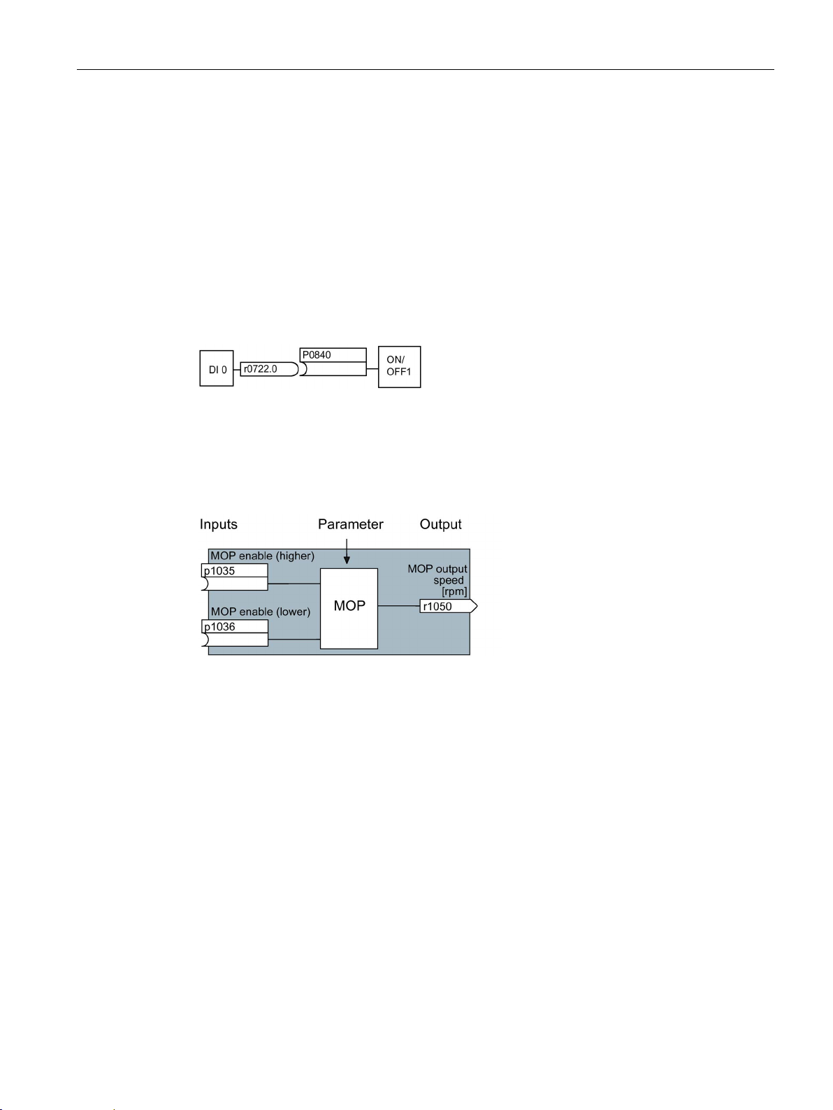
Image 2-1 Example: Pre-assigned signal interconnection for digital input 0 of a non-bus-capable
Control Unit
The functions can be parameterized and interconnected as required. The signal
interconnection of the functions is realized, contrary to electric circuitry, not using cables, but
in the software. The various functions use a range of inputs, outputs, and parameters.
Image 2-2 Example: MOP function (motorized potentiometer)
Connectors and binectors are elements used to exchange signals between the individual
functions. Connectors and binectors can be seen as "storage compartments":
● Connectors are used to store "analog" signals (e.g. speed setpoint)
● Binectors are used to store "digital" signals (e.g. 'MOP raise' command)
BICO technology describes the type of parameterization that can be used to disconnect all
the internal signal interconnections between the functions or establish new connections. This
is realized using
Connector Technology)
SINAMICS G110D
Operating Instructions, 07/2016, FW V3.63, A5E36768472B AB
nectors and Connectors. Hence the name
technology. ( Binector
23
Introduction
BICO parameters
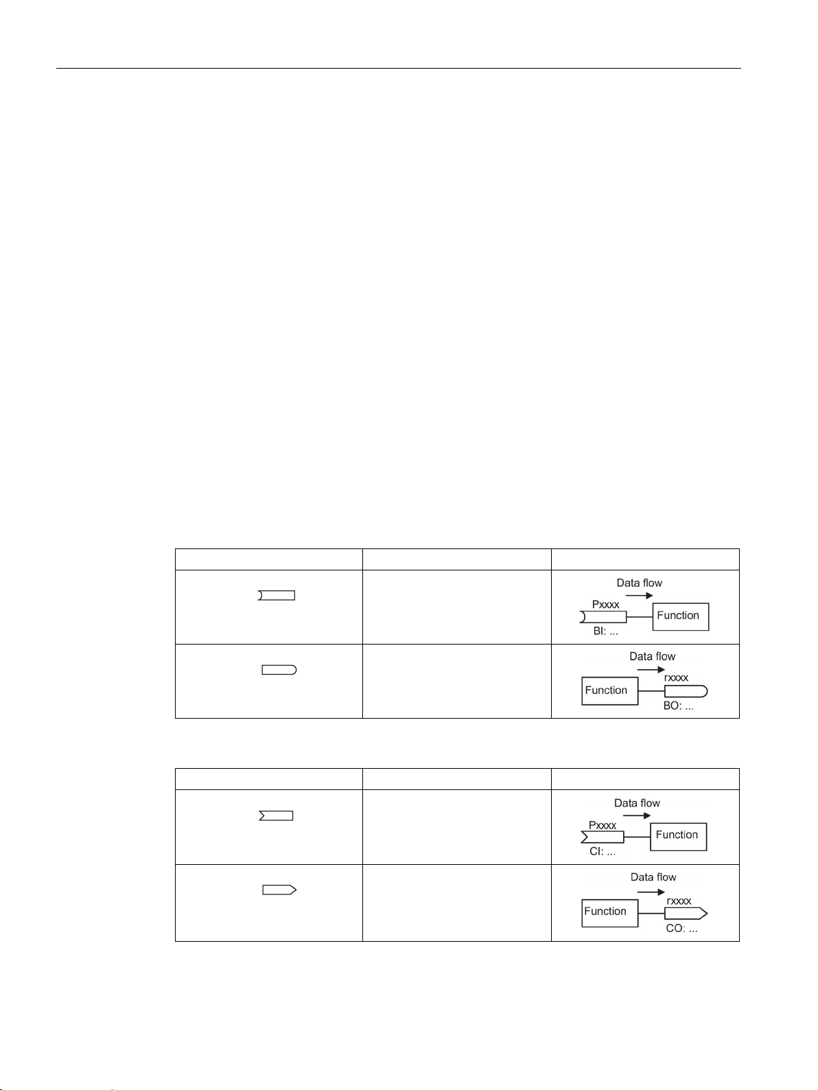
BICO symbols, representation, and description
Abbreviation and symbol
Description
Function
Abbreviation and symbol
Description
Function
2.3 Extended adaptation of parameters
You can use the BICO parameters to define the sources of the input signals of a function.
This means that using BICO parameters you can define from which connectors and
binectors a function reads-in its input signals, thereby enabling you to "interconnect" the
functions stored in the devices in accordance with your requirements. Five different BICO
parameter types are available:
● Binector inputs: BI
● Connector inputs: CI
● Binector outputs: BO
● Connector outputs: CO
● Binector/connector outputs: CO/BO
Binector/connector outputs (CO/BO) are parameters that combine more than one binector
output in a single word (e.g. r0052 CO/BO: status word 1). Each bit in the word represents a
digital (binary) signal. This feature reduces the number of parameters and makes it easier to
set parameters by means of the serial interface (data transfer).
BICO parameters of type CO, BO, or CO/BO can be used more than once.
Table 2- 9 Binector symbols
BI
BO
Table 2- 10 Connector symbols
CI
CO
Binector input
Binector output
Connector input
Connector output
SINAMICS G110D
24 Operating Instructions, 07/2016, FW V3.63, A5E36768472B AB

Introduction
Abbreviation and symbol
Description
Function
When do you need to use BICO technology?
What precautions should you take when using BICO technology?
What sources of information do you need to help you set parameters using BICO
technology?
2.3 Extended adaptation of parameters
Table 2- 11 Connector and binector output symbols
Binector/connector output
BICO technology allows you to adapt the inverter to a wide range of different requirements.
This does not necessarily have to involve highly complex functions.
Example 1: Assign a different function to a digital input.
Example 2: Switch over the speed setpoint from the fixed frequency to the analog input.
Always apply caution when handling internal interconnections. Note which changes you
make as you go along since the process of analyzing them later can be quite difficult.
The STARTER commissioning tool offers various screens that make it much easier for you
to use BICO technology. The signals that you can interconnect are displayed in plain text,
which means that you do not need any prior knowledge of BICO technology.
● This manual is sufficient for simple signal interconnections, e.g. assigning a different
significance to the to digital inputs.
● The parameter list in the List Manual is sufficient for signal interconnections that go
beyond just simple ones.
● You can also refer to the function diagrams in the List Manual for complex signal
interconnections.
SINAMICS G110D
Operating Instructions, 07/2016, FW V3.63, A5E36768472B AB
25
Introduction
2.3.2
BICO technology: example
Example: Shifting a basic PLC functionality into the inverter
Parameter
Description
P0003 = 3
Enable expert access to parameters
P0700 = 2
Select the command source: Digital inputs
P0701 (e.g.) = 99
Enable/"open" digital input 0 (DI0) for BICO parameterization
P0702 (e.g.) = 99
Enable/"open" digital input 1 (DI1) for BICO parameterization
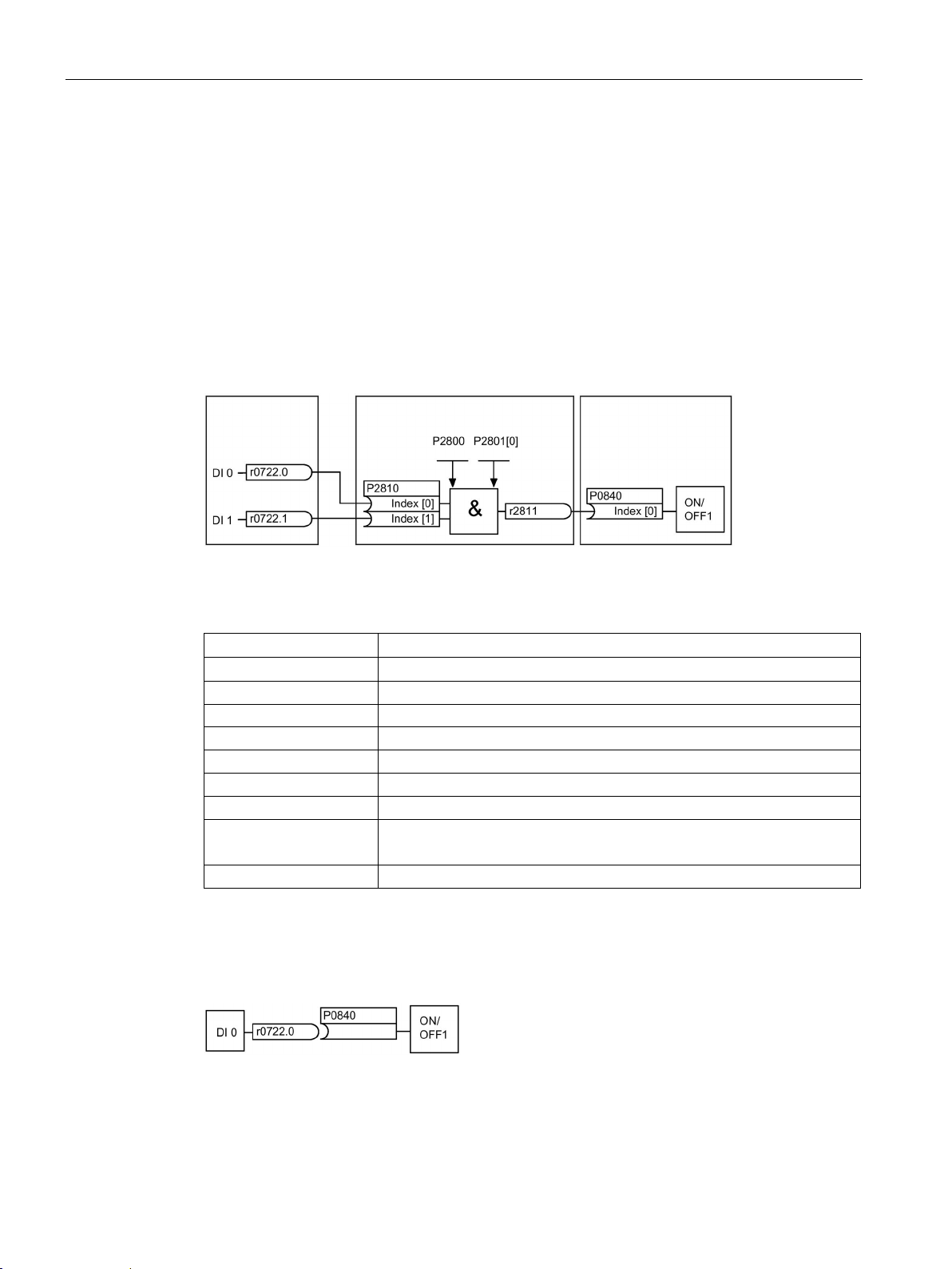
P2801 [In000] = 1
Individual enable of the AND function block
P2810 [In000] = 722.0
Connect the status of DI0 to the 2nd AND
r0722.1 = Parameter that displays the status of digital input 1.
P0840 = r2811
Connect the AND output to the control command ON/OFF1
Explanations of the example
Open the default signal interconnection for BICO parameterization
2.3 Extended adaptation of parameters
A conveyor system is to be configured in such a way that it can only start when two signals
are present simultaneously. These could be the following signals, for example:
● The light barrier has been activated
● The protective door is closed
The task is realized by inserting free blocks between the digital input 0 and the internal ON
command for the motor and interconnecting them.
Image 2-3 Example: Signal interconnection for interlock
Table 2- 12 Parameterizing an interlock
P2800 = 1 Group enable all freely-programmable function blocks (FFB)
P2810 [In001] = r0722.1 Connect the status of DI1 to the 2nd AND input
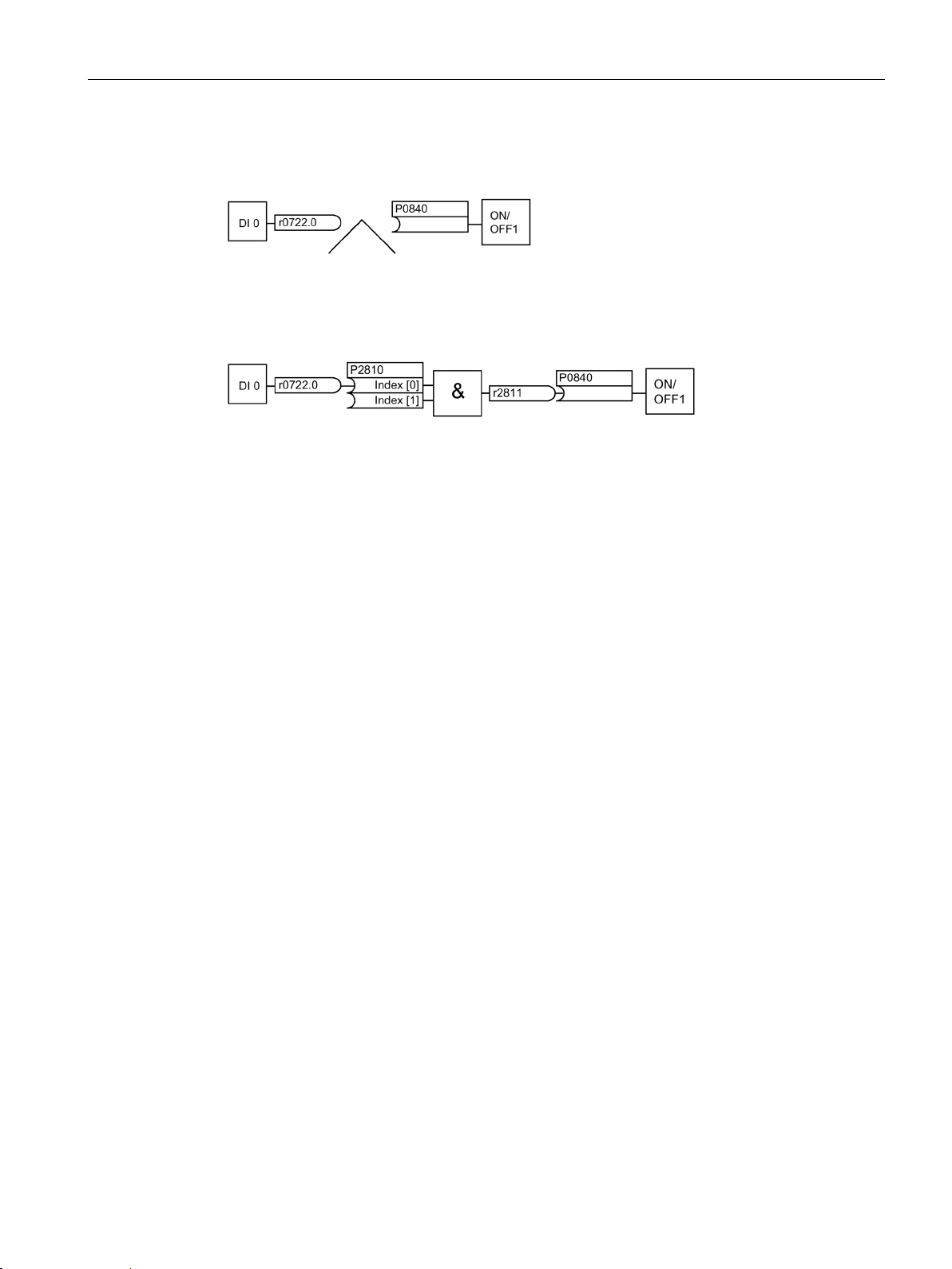
The default setting P0701 = 1 indicates the following internal signal interconnection:
Image 2-4 Default parameterization
SINAMICS G110D
26 Operating Instructions, 07/2016, FW V3.63, A5E36768472B AB
Introduction
Principle of connecting functions by means of BICO technology
2.3 Extended adaptation of parameters
The setting P0701 = 99 means that a pre-assigned signal interconnection is disconnected
and therefore the connection opened for BICO parameterization.
Image 2-5 BICO parameterization
When P0701 = 99, the binector input of the ON/OFF1 function (P0840) is available for
activation by a signal source other than r0722.0 (in this case r2811).
Image 2-6 Interconnection after insertion of two functions
A connection between two functions comprises a connector/binector and a BICO parameter.
Connections are always established with respect to the input of a particular function, which
means that the output of an upstream function must always be assigned to the input of a
downstream function. The assignment is always made by entering the number of the
connector/binector from which the required input signals are read in a BICO parameter.
SINAMICS G110D
Operating Instructions, 07/2016, FW V3.63, A5E36768472B AB
27

Introduction
2.3 Extended adaptation of parameters
SINAMICS G110D
28 Operating Instructions, 07/2016, FW V3.63, A5E36768472B AB

3
3.1
Overview of SINAMICS G110D Inverters
SINAMICS G110D Inverters
The SINAMICS G110D has been designed to provide an adaptable solution to conveyor
technology applications.
Each SINAMICS G110D Inverter is a complete Power Module and Control Unit in one
unique housing which is IP65 rated. The power output range extends from 0.75 kW to 7.5
kW.
The optional STARTER software allows commissioning of the Inverter using a PC with the
optional optical cables.
A range of additional, application-specific components are also available, for example,
braking resistors.
SINAMICS G110D
Operating Instructions, 07/2016, FW V3.63, A5E36768472B AB
29
Description
3.2
Components of the Inverter system
The Inverter system
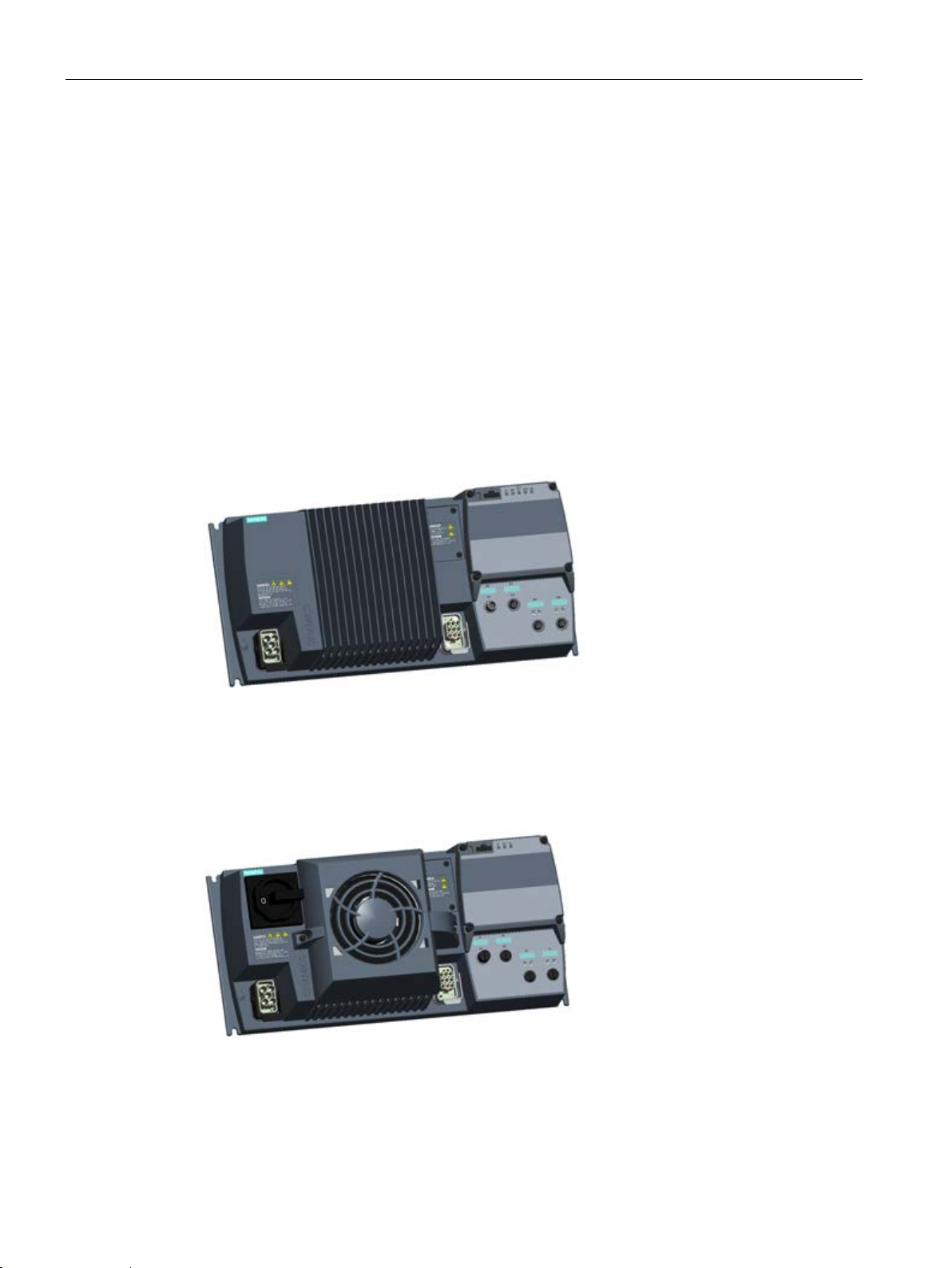
Frame size A (FSA)
Frame size B (FSB)
3.2 Components of the Inverter system
The Inverter is available in three frame sizes:
6SL3511-0PE17-5AM0 - 0.75 kW
6SL3511-1PE17-5AM0 - 0.75 kW with repair switch
6SL3511-0PE21-5AM0 - 1.5 kW
6SL3511-1PE21-5AM0 - 1.5 kW with repair switch
6SL3511-0PE23-0AM0 - 3.0 kW
6SL3511-1PE23-0AM0 - 3.0 kW with repair switch
Image 3-1 SINAMICS G110D FSA
6SL3511-0PE24-0AM0 - 4.0 kW
6SL3511-1PE24-0AM0 - 4.0 kW with repair switch
Image 3-2 SINAMICS G110D FSB
SINAMICS G110D
30 Operating Instructions, 07/2016, FW V3.63, A5E36768472B AB
 Loading...