

Siemens SINAMICS G110 Operating Instructions Manual

Operating Instructions Edition 04/2005
sinamics
SINAMICS G110

SINAMICS G110 Documentation
Getting Started Guide
The Getting Started Guide is designed to give
the user quick access to all the basic
information required to install and set-up the
SINAMICS G110 for operation.
Operating Instructions
Gives information regarding the features of
SINAMICS G110 including Installation,
Commissioning, Control modes, System
Parameter structure, Troubleshooting,
Specifications and available options for the
inverter.
Parameter List
The Parameter List contains a detailed
description of all Parameters relating to the
SINAMICS G110 and is structured in
numerical order.
Catalogues
In the catalogue you will find all the necessary
information to select an appropriate inverter,
as well as the Basic Operator Panel and
Communication Options for the
SINAMICS G110 series.

SINAMICS G110
120 W - 3 kW
Operating Instructions
User Documentation
Inverter Type
SINAMICS G110
Firmware Version
1.0 &1.1
(See Page 4)
Issue 04/2005
Overview
1
Installation
2
Commissioning
3
Using the
SINAMICS G110
4
System Parameters
5
Troubleshooting
6
Specifications
7
Options
8
Electro-Magnetic
Compatibility
9
Appendices
A
B
C
D
E
F
Index

SINAMICS G110 Operating Instructions
4 6SL3298-0AA11-0BP0
Summary of Amendments
Edition Valid for
firmware
version
Status/Changes Order no of the inverter
6SL3211-0xxxx-xxxx
04/2003 1.0 First issue Last digit “0”
6SL3211-0xxxx-xxx0
11/2004 1.0
1.1
New features inserted:
Types of Control using the Terminals (2 wire/3 wire control)
4.3.4 Parameter P1234 in DC braking
4.3.5 Compound braking
Last digit “0”
6SL3211-0xxxx-xxx0
Last digit “1”
6SL3211-0xxxx-xxx1
04/2005 6.1 Troubleshooting with Standard Inverter LED - timings of
LED has been updated.
Approved Siemens Quality for Software and Training
is to DIN ISO 14001, Reg. No. 2160-01
The reproduction, transmission or use of this document, or
its contents is not permitted unless authorized in writing.
Offenders will be liable for damages. All rights including
rights created by patent grant or registration of a utility
model or design are reserved.
© Siemens AG 2005. All Rights Reserved.
SINAMICS® is a registered trademark of Siemens.
Other functions not described in this document may be
available. However, this fact shall not constitute an
obligation to supply such functions with a new control, or
when servicing.
We have checked that the contents of this document
correspond to the hardware and software described.
There may be discrepancies nevertheless, and no
guarantee can be given that they are completely
identical. The information contained in this document is
reviewed regularly and any necessary changes will be
included in the next edition. We welcome suggestions for
improvement.
Siemens handbooks are printed on chlorine-free paper
that has been produced from managed sustainable
forests. No solvents have been used in the printing or
binding process.
Document subject to change without prior notice.
Order Number. 6SL3298-0AA11-0BP0
Printed on demand in Fürth, Germany
Siemens-Aktiengesellschaft.

04/2005 Important Information
SINAMICS G110 Operating Instructions
6SL3298-0AA11-0BP0
5
Important Information
WARNING
Before installing and commissioning the inverter, you must read all safety
instructions and warnings carefully including all the warning labels attached to the
equipment. Make sure that the warning labels are kept in a legible condition.
Use for intended purpose only
The equipment may be used only for the application stated in the manual and only
in conjunction with devices and components recommended and authorized by
Siemens.
Information is also available from:
Technical Support Nuremberg
Tel: +49 (0) 180 5050 222
Fax: +49 (0) 180 5050 223
Email: adsupport@siemens.com
Monday to Friday: 7:00 am to 5:00 pm (local time)
Internet Home Address
Customers can access technical and general information at:
http://www.siemens.de/sinamics-g110
Contact address
Should any questions or problems arise while reading this manual, please contact
the Siemens office concerned using the form provided at the back this manual.
Definitions 04/2005
SINAMICS G110 Operating Instructions
6 6SL3298-0AA11-0BP0
Definitions
DANGER
For the purpose of this documentation and the product warning labels, “Danger”
indicates an imminently hazardous situation which, if not avoided, will result in
death or serious injury.
WARNING
For the purpose of this documentation and the product warning labels, "Warning"
indicates a potentially hazardous situation which, if not avoided, could result in
death or serious injury.
CAUTION
Used in conjunction with the safety alert symbol indicates a potentially hazardous
situation which, if not avoided, may result in minor or moderate injury.
CAUTION
Used without the safety alert symbol indicates a potentially hazardous situation
which, if not avoided, may result in property damage.
NOTICE
Indicates a potential situation which, if not avoided, may result in an undesirable
result or state.
NOTE
For the purpose of this documentation, "Note" indicates important information
relating to the product or highlights part of the documentation for special attention.
Qualified personnel
For the purpose of this Instruction Manual and product labels, a "Qualified person"
is someone who is familiar with the installation, mounting, start-up and operation of
the equipment and the hazards involved.
He or she must have the following qualifications:
1. Trained and authorized to energize, de-energize, clear, ground and tag circuits
and equipment in accordance with established safety procedures.
2. Trained in the proper care and use of protective equipment in accordance with
established safety procedures.
3. Trained in rendering first aid.
¾ PE – Protective Earth uses circuit protective conductors sized for short circuits
where the voltage will not rise in excess of 50 volts. This connection is normally
used to ground the inverter.
¾
- Is the ground connection where the reference voltage can be the same as
the Earth voltage. This connection is normally used to ground the motor.
04/2005 Safety Instructions
SINAMICS G110 Operating Instructions
6SL3298-0AA11-0BP0
7
Safety Instructions
The following Warnings, Cautions and Notes are provided for your safety and as a
means of preventing damage to the product or components in the machines
connected. This section lists Warnings, Cautions and Notes, which apply generally
when handling SINAMICS G110 Inverters, classified a s General, Transport &
Storage, Commissioning, Operation, Repair and Dismantling & Disposal.
Specific Warnings, Cautions and Notes that apply to particular activities are
listed at the beginning of the relevant chapters and are repeated or supplemented
at critical points throughout these sections.
Please read the information carefully, since it is provided for your personal
safety and will also help prolong the service life of your SINAMICS G110
Inverter and the equipment you connect to it.
General
WARNINGS
¾ This equipment contains dangerous voltages and controls potentially dangerous
rotating mechanical parts. Non-compliance with Warnings or failure to follow
the instructions contained in this manual can result in loss of life, severe
personal injury or serious damage to property.
¾ Only suitable qualified personnel should work on this equipment, and only after
becoming familiar with all safety notices, installation, operation and
maintenance procedures contained in this manual. The successful and safe
operation of this equipment is dependent upon its proper handling, installation,
operation and maintenance.
¾ Risk of electric shock. The DC link capacitors remain charged for five minutes
after power has been removed. The equipment SHOULD NOT be opened
until 5 minutes after the power has been removed.
¾ The horsepower (hp) ratings used throughout this document are obtained by
comparison to the Siemens 1LA6 and 1LA7 motors and not NEMA/UL rated
motors.
CAUTION
¾ Children and the general public must be prevented from accessing or
approaching the equipment!
¾ This equipment may only be used for the purpose specified by the
manufacturer. Unauthorized modifications and the use of spare parts and
accessories that are not sold or recommended by the manufacturer of the
equipment can cause fires, electric shocks and injuries.
NOTES
¾ Keep these operating instructions within easy reach of the equipment and make
them available to all users
¾ Whenever measuring or testing has to be performed on live equipment, the
regulations of Safety Code VBG 4.0 must be observed, in particular §8
“Permissible Deviations when Working on Live Parts”. Suitable electronic tools
should be used.
¾ Before installing and commissioning, please read these safety instructions and
warnings carefully and all the warning labels attached to the equipment. Make
sure that the warning labels on the inverter are kept in a legible condition.
Safety Instructions 04/2005
SINAMICS G110 Operating Instructions
8 6SL3298-0AA11-0BP0
Transport & Storage
WARNING
Correct transport, storage, erection and mounting, as well as careful operation and
maintenance are essential for proper and safe operation of the equipment.
CAUTION
Protect the inverter against physical shocks and vibration during transport and
storage. Also be sure to protect it against water (rainfall) and excessive
temperatures (see Section 2.3 on page 18).
Commissioning
WARNINGS
¾ Work on the device/system by unqualified personnel or failure to comply with
warnings can result in severe personal injury or serious damage to material.
Only suitably qualified personnel trained in the setup, installation,
commissioning and operation of the product should carry out work on the
device/system.
¾ Only permanently-wired input power connections are allowed. This equipment
must be grounded (IEC 536 Class 1, NEC and other applicable standards).
¾ If a Residual Current-operated protective Device (RCD) is to be used, it must be
an RCD type B. However, if the SINAMICS G110 inverter is connected to a
single-phase grounded-neutral star mains network, a n RCD of type A is
permissible.
¾ The following terminals can carry dangerous voltages even if the inverter is
inoperative:
♦ the power supply terminals L1 and L2/N.
♦ the motor terminals U, V, W and the terminals DC+ and DC-.
¾ This equipment must not be used as an ‘emergency stop mechanism’ (see EN
60204, 9.2.5.4)
CAUTION
The connection of power, motor and control cables to the inverter must be carried
out as shown in Figure 2-8 on page 28, to prevent inductive and capacitive
interference from affecting the correct functioning of the inverter.
04/2005 Safety Instructions
SINAMICS G110 Operating Instructions
6SL3298-0AA11-0BP0
9
Operation
WARNINGS
¾ SINAMICS G110 inverters operate at high voltages.
¾ When operating electrical devices, it is impossible to avoid applying hazardous
voltages to certain parts of the equipment.
¾ Emergency Stop facilities according to EN 60204 IEC 204 (VDE 0113) must
remain operative in all operating modes of the control equipment. Any
disengagement of the Emergency Stop facility must not lead to uncontrolled or
undefined restart.
¾ Wherever faults occurring in the control equipment can lead to substantial
material damage or even grievous bodily injury (i.e. potentially dangerous
faults), additional external precautions must be taken or facilities provided to
ensure or enforce safe operation, even when a fault occurs (e.g. independent
limit switches, mechanical interlocks, etc.).
¾ Certain parameter settings may cause the inverter to restart automatically after
an input power failure.
¾ Motor parameters must be accurately configured for motor overload protection
to operate correctly above 5 Hz.
¾ This equipment is capable of providing internal motor overload protection in
accordance with UL508C. Refer to P0610 and P0335, I
2
t is ON by default.
¾ This equipment is suitable for use in a circuit capable of delivering not more
than 10,000 symmetrical amperes (rms), for a maximum voltage of 230 V when
protected by an H or K type fuse, a circuit breaker or self-protected combination
motor controller.
¾ This equipment must not be used as an ‘emergency stop mechanism’ (see EN
60204, 9.2.5.4)
Repair
WARNINGS
¾ Repairs on equipment may only be carried out by Siemens Service, by repair
centers authorized by Siemens or by qualified personnel who are thoroughly
acquainted with all the warnings and operating procedures contained in this
manual.
¾ Any defective parts or components must be replaced using genuine Siemens
authorized parts.
¾ Risk of electric shock. Wait 5 minutes for the DC capacitors to discharge before
carrying out any installation work.
Dismantling & Disposal
NOTES
¾ The inverter’s packaging is re-usable. Retain the packaging for future use or
return it to the manufacturer.
¾ Easy-to-release screw and snap connectors allow you to break the unit down
into its component parts. You can then re-cycle these component parts, dispose
of them in accordance with local requirements or return them to the
manufacturer.

Safety Instructions 04/2005
SINAMICS G110 Operating Instructions
10 6SL3298-0AA11-0BP0

04/2005 Overview
SINAMICS G110 Operating Instructions
6SL3298-0AA11-0BP0
11
Table of Contents
1 Overview................................................................................................................ 15
1.1 The SINAMICS G110 ............................................................................................. 15
1.2 Features..................................................................................................................15
2 Installation............................................................................................................. 17
2.1 General................................................................................................................... 17
2.2 Power Losses ......................................................................................................... 18
2.3 Ambient operating conditions ................................................................................. 18
2.4 Harmonic Currents.................................................................................................. 19
2.5 Derating with Pulse Frequencies............................................................................ 19
2.6 Overvoltage and Trip Levels...................................................................................19
2.7 Overcurrent Trip Levels .......................................................................................... 19
2.8 Mechanical Installation ........................................................................................... 20
2.9 Electrical Installation............................................................................................... 23
2.10 SINAMICS G110 Flat Plate Variant........................................................................29
3 Commissioning..................................................................................................... 31
3.1 Block Diagram......................................................................................................... 32
3.2 Commission Modes ................................................................................................ 33
3.3 Basic Commissioning.............................................................................................. 34
3.4 Advanced Commissioning...................................................................................... 40
4 Using the SINAMICS G110................................................................................... 53
4.1 Frequency Setpoint (P1000)...................................................................................53
4.2 Command Sources (P0700)................................................................................... 54
4.3 Types of Control using the Terminals.....................................................................55
4.4 OFF and Braking Functions....................................................................................61
4.5 Control Modes (P1300)........................................................................................... 62
4.6 Faults and Alarms................................................................................................... 62
5 System Parameters .............................................................................................. 63
5.1 Introduction to SINAMICS G110 System Parameters............................................63
5.2 Parameter Overview............................................................................................... 64
6 Troubleshooting.................................................................................................... 65
6.1 Troubleshooting with the Standard Inverter LED.................................................... 65
6.2 Troubleshooting with the BOP................................................................................ 65
7 SINAMICS G110 Specifications........................................................................... 67
8 Options .................................................................................................................. 71

Overview 04/2005
SINAMICS G110 Operating Instructions
12 6SL3298-0AA11-0BP0
9 Electro-Magnetic Compatibility (EMC)................................................................ 73
9.1 Electro-Magnetic Compatibility (EMC).................................................................... 73
A Removal of ‘Y’ Capacitor Link............................................................................. 79
B DIN Rail Mounting Kit........................................................................................... 80
C Fitting the Basic Operator Panel......................................................................... 82
D Description of the BOP ........................................................................................ 83
E Applicable Standards ........................................................................................... 84
F List of Abbreviations............................................................................................85
Index ................................................................................................................................ 87

04/2005 Overview
SINAMICS G110 Operating Instructions
6SL3298-0AA11-0BP0
13
List of Illustrations
Figure 2-1 Reforming Capacitors After a Period of Storage..................................................................19
Figure 2-2 Derating for Altitude..............................................................................................................20
Figure 2-3 Dimensions of the SINAMICS G110.....................................................................................23
Figure 2-4 Clearance distances for mounting the inverter.....................................................................24
Figure 2-5 SINAMICS G110 Connection Terminals...............................................................................27
Figure 2-6 SINAMICS G110 DC Terminals Connections.......................................................................27
Figure 2-7 Motor and Power Connections.............................................................................................29
Figure 2-8 Wiring Guidelines to Minimize the Effects of EMI.................................................................30
Figure 2-9 SINAMICS G110 Flat Plate Variant...................................................................................... 31
Figure 3-1 Inverter block diagram..........................................................................................................34
Figure 3-2 Motor Base Frequency DIP Switch and Bus Termination.....................................................36
Figure 3-3 Basic operation – Analog and USS Variants........................................................................ 37
Figure 3-4 BOP......................................................................................................................................39
Figure 3-5 Changing parameters via the BOP....................................................................................... 40
Figure 3-6 Typical Motor Rating Plate Example....................................................................................48
Figure 3-7 Motor Overload PTC Connection ......................................................................................... 51
Figure 3-8 Typical Configurations of the Digital Output.........................................................................52
Figure 4-1 Siemens standard control using ON/OFF1 and REV ........................................................... 58
Figure 4-2 Siemens standard control using ON/OFF1 and ON_REV/OFF1..........................................59
Figure 4-3 2-wire control using ON_FWD and ON_REV....................................................................... 60
Figure 4-4 3-wire control using FWDP, REVP and STOP ..................................................................... 61
Figure 4-5 3-wire control using ON_PULSE, OFF1/HOLD and REV.....................................................62
Figure 5-1 Parameter Overview.............................................................................................................66
List of Tables
Table 2-1 Dimensions of the SINAMICS G110 Inverter........................................................................20
Table 2-2 Mounting Tightening Torques of SINAMICS G110...............................................................22
Table 2-3 Flat Plate Power Losses and Thermal Specifications* ......................................................... 30
Table 3-1 Factory settings for operation using the standard inverter (Analog Variant).........................35
Table 3-2 Factory settings for operation using the standard inverter (USS Variant).............................36
Table 3-3 Modes of Operation Overview..............................................................................................41
Table 3-4 Commissioning Overview.....................................................................................................44
Table 4-1 Redefined Digital Inputs .......................................................................................................55
Table 7-1 SINAMICS G110 Performance Ratings................................................................................67
Table 7-2 Control Terminals Screwless Type – Wire Sizes.................................................................. 68
Table 7-3 Tightening Torques – Power Terminals................................................................................ 68
Table 7-4 SINAMICS G110 Specifications, Frame Size A ..................................................................68
Table 7-5 Frame Sizes B and C ...........................................................................................................69
Table 7-6 Power losses SINAMICS G110 (230 V) inverters.................................................................69
Table 7-7 Harmonic currents Single Phase 230 V................................................................................70
Table 7-8 Derating with Pulse Frequencies..........................................................................................70
Table 9-1 Harmonic currents................................................................................................................74
Table 9-2 Case 1 - General Industrial...................................................................................................75
Table 9-3 Case 2 - Filtered Industrial ...................................................................................................75
Table 9-4 Case 3 - Filtered for Residential, Commercial and Light Industry.........................................76
Table 9-5 Compliance Table ................................................................................................................77

Overview 04/2005
SINAMICS G110 Operating Instructions
14 6SL3298-0AA11-0BP0

04/2005 Overview
SINAMICS G110 Operating Instructions
6SL3298-0AA11-0BP0
15
1 Overview
1.1 The SINAMICS G110
The SINAMICS G110s are a range of frequency inverters for controlling the speed
of three phase AC motors, incorporating the CPM 110 controlled power module.
The various models available range from 120 W to 3.0 kW single-phase input.
The inverters are microprocessor-controlled and use state-of-the-art Insulated Gate
BipoIar Transistor (IGBT) technology. This makes them reliable and versatile. A
special pulse-width modulation method with selectable pulse frequency permits
quiet motor operation. Comprehensive protective functions provide excellent
inverter and motor protection.
The SINAMICS G110 CPM110 with its default factory settings is ideal for a large
range of simple V/f motor control applications. Using the comprehensive range of
programmable parameters provided with the inverter, the unit can be adapted for a
wide range of applications. Parameters can be changed using either USS
communications or the Basic Operator Panel (BOP).
The SINAMICS G110 is available in two variants; the Analog controlled variant and
the USS controlled variant utilizing RS485 protocol. They are available as filtered
and unfiltered inverters including a “Flat Plate” version which completes the range.
They can be used in both 'stand-alone' applications as well as being integrated into
'Automation Systems'.
1.2 Features
Main Characteristics
¾ Easy installation
¾ Easy commission
♦ Quick commissioning
♦ Reset function (allowing the reset of all values to the preset factory defaults)
¾ Rugged EMC design
¾ Can be operated on IT line supplies (unfiltered variants)
¾ 1 digital output – Isolated optocoupler
¾ 3 digital inputs (non-isolated)
¾ 1 Analog input, AIN: 0 – 10 V (Analog variant only). Can be used as 4
th
digital
input
¾ High pulse frequencies for low-noise motor operation
¾ Status information and alarm messages using the Basic Operator Panel
¾ Optional Basic Operator Panel with the capability to clone parameter sets
¾ USS communications interface (USS variant only)
¾ PC to RS232 Connection Kit available

Overview 04/2005
SINAMICS G110 Operating Instructions
16 6SL3298-0AA11-0BP0
Performance Characteristics
¾ Fast repeatable response time to control signals
¾ Fast Current Limitation (FCL) for trip-free operation
¾ Built-in DC injection brake
¾ Compound braking
¾ Fixed Frequencies
¾ Motor potentiometer function
¾ Acceleration/deceleration times with programmable smoothing
¾ Multi-point V/f characteristic
¾ 150% overload for 60 seconds
¾ 2-wire/3-wire control
¾ Automatic restart after a mains failure
¾ Flying start
Protection Characteristics
¾ Overvoltage/undervoltage protection
¾ Overtemperature protection for the inverter
¾ Ground fault protection
¾ Short-circuit protection
¾ I
2
t thermal motor protection
¾ Motor stall prevention
04/2005 Installation
SINAMICS G110 Operating Instructions
6SL3298-0AA11-0BP0
17
2 Installation
WARNINGS
¾ Work on the device/system by unqualified personnel or failure to comply with
warnings can result in severe personal injury or serious damage to material.
Only suitably qualified personnel trained in the setup, installation,
commissioning and operation of the product should carry out work on the
device/system.
¾ Only permanently-wired input power connections are allowed. This equipment
must be grounded (IEC 536 Class 1, NEC and other applicable standards).
¾ If a Residual Current-operated protective Device (RCD) is to be used, it must be
an RCD type B. However, if the SINAMICS G110 inverter is connected to a
single-phase grounded-neutral star mains network, a n RCD of type A is
permissible.
¾ The mains input, DC and motor terminals, can carry dangerous voltages even if
the inverter is inoperative; wait 5 minutes to allow the unit to discharge after
switching off before carrying out any installation work.
¾ This equipment must not be used as an ‘emergency stop mechanism’ (see EN
60204, 9.2.5.4)
¾ The minimum size of the earth-bonding conductor must be equal to or greater
than the cross-section of the power supply cables.
¾ Safety regulations must not be compromised when installing inverters!
CAUTION
The connection of power, motor and control cables to the inverter must be carried
out as shown in Figure 2-8 on page 28, to prevent inductive and capacitive
interference from affecting the correct functioning of the inverter.
2.1 General
Installation after a Period of Storage
Following a prolonged period of storage, you must reform the capacitors in the
inverter. It is important that the time of storage is calculated from the time of
manufacture and not the time of delivery. The requirements are shown below.
Figure 2-1 Reforming Capacitors After a Period of Storage

Installation 04/2005
SINAMICS G110 Operating Instructions
18 6SL3298-0AA11-0BP0
The serial numbers consist 13 characters and contains the date of manufacture,
e.g. XAP214-123456
XAP214-123456 Characters 1-2 are the site where the product is built
XAP214-123456 Character 3 denotes the year e.g. R = 2003
XAP214-123456 Character 4 is the month (1-9 =Jan-Sep, O =Oct, N = Nov, D =Dec)
XAP214-123456 Characters 5-6 are the day of the month
XAP214-123456 Character 7 is a separator
XAP214-123456 Characters 8-13 are the sequential serial number 1-999999
2.2 Power Losses
For information on the typical power losses for the SINAMICS G110 inverter,
please consult Table 7-6 on page 69.
2.3 Ambient operating conditions
Temperature
-10ºC to +50ºC (14ºF to 122ºF) see Table 7-8 on page 70 for derating information.
Humidity Range
≤ 95% Non-condensing
Altitude
If the inverter is to be installed at an altitude greater than 1000m, derating will be
required. Figure 2-2 below shows the permissible rated input voltages and outp ut
current for inverter installations from 1000 m to 4000 m above sea level.
Figure 2-2 Derating for Altitude
Shock and Vibration
Do not drop the inverter or expose to sudden shock. Do not install the inverter in an
area where it is likely to be exposed to constant vibration.
Mechanical strength to EN 60721-3-3
¾ Deflection: 0.075 mm (10 … 58 Hz)
¾ Acceleration: 10 m/s
2
(58 … 200 Hz)
Electromagnetic Radiation
Do not install the inverter near sources of electromagnetic radiation.
04/2005 Installation
SINAMICS G110 Operating Instructions
6SL3298-0AA11-0BP0
19
Atmospheric Pollution
Do not install the inverter in an environment, which contains atmospheric pollutants
such as dust, corrosive gases, etc.
Water
Take care to site the inverter away from potential water hazards, e.g. do not install
the inverter beneath pipes that are subject to condensation. Do not install the
inverter where excessive humidity and condensation may occur.
Installation and overheating
WARNING
The inverter MUST be front mounted in a vertical position to ensure optimum
cooling.
Ensure that the inverter’s air vents are not obstructed. For the recommended
clearance distances see Figure 2-4 on page 22.
2.4 Harmonic Currents
For details of the harmonic currents with relation to the SINAMICS G110 inverter,
please see Table 9-1on page 74.
2.5 Derating with Pulse Frequencies
For details of derating with pulse frequencies with relation to the SINAMICS G110
inverter, please refer to Table 7-8 on page 70.
2.6 Overvoltage and Trip Levels
The inverter will protect itself from overvoltage and undervoltage. Internal
overvoltage can occur during braking where internal voltages are forced high by
energy from an external load.
WARNING
Although the inverter is designed to protect itself from overvoltage (if correctly
commissioned); connecting the inverter to a voltage supply that is excessively high
could result permanent damage to the inverter and seriously injure the user.
2.7 Overcurrent Trip Levels
The inverter will protect itself from short circuits between motor phases and from
the motor phases to earth. The inverter will also protect itself against motor
overload conditions which can produce excess currents.
Installation 04/2005
SINAMICS G110 Operating Instructions
20 6SL3298-0AA11-0BP0
2.8 Mechanical Installation
WARNING
¾ To ensure the safe operation of the equipment, it must be installed and
commissioned by qualified personnel in full compliance with the warnings laid
down in these operating instructions.
¾ Take particular note of the general and regional installation and safety
regulations regarding work on dangerous voltage installations (e.g. EN 50178),
as well as the relevant regulations regarding the correct use of tools and
personal protective equipment (PPE).
¾ Never use high voltage insulation test equipment on cables connected to the
inverter.
¾ The mains input, DC and motor terminals, can carry dangerous voltages even if
the inverter is inoperative; wait 5 minutes to allow the unit to discharge after
switching off before carrying out any installation work.
CAUTION
The control, power supply and motor leads must be laid separately. Do not feed
them through the same cable conduit/trunking.
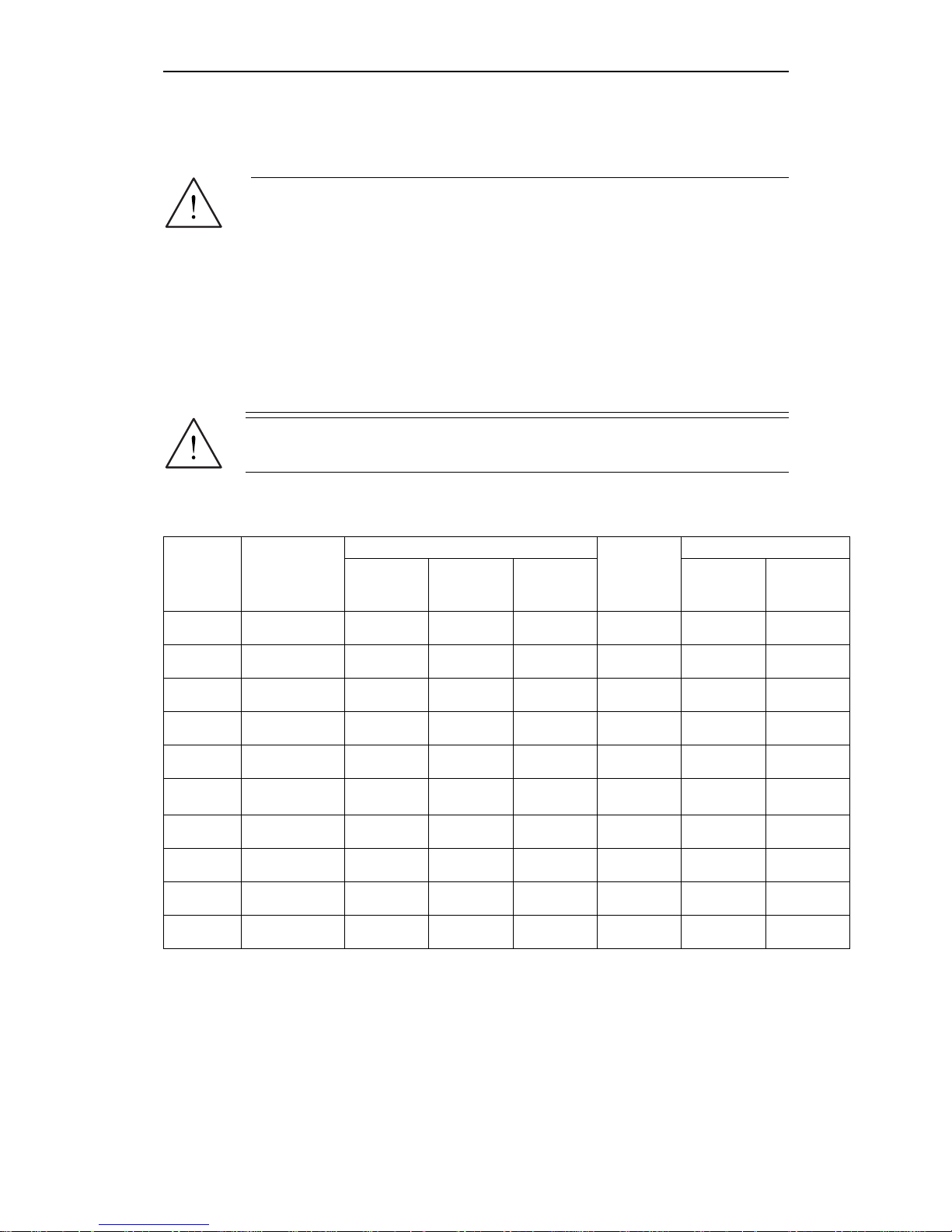
Table 2-1 Dimensions of the SINAMICS G110 Inverter
Overall Dimensions Drilling Dimensions
Frame Size Output
H
mm
(inches)
W
mm
(inches)
D
mm
(inches)
Depth with
BOP fitted
mm
(inches)
H1
mm
(inches)
W2
mm
(inches)
A 120 W
150
(5.91)
90
(3.54)
116
(4.57)
124
(4.88)
140
(5.51)
79
(3.11)
A 250 W
150
(5.91)
90
(3.54)
116
(4.57)
124
(4.88)
140
(5.51)
79
(3.11)
A 370 W
150
(5.91)
90
(3.54)
116
(4.57)
124
(4.88)
140
(5.51)
79
(3.11)
A 550 W
150
(5.91)
90
(3.54)
131
(5.16)
139
(5.47)
140
(5.51)
79
(3.11)
A 750 W
150
(5.91)
90
(3.54)
131
(5.16)
139
(5.47)
140
(5.51)
79
(3.11)
A
(Flat Plate)
120 W – 750 W
150
(5.91)
90
(3.54)
101
(4.01)
109
(4.29)
140
(5.51)
79
(3.11)
B 1.1 kW
160
(6.30)
140
(5.51)
142
(5.59)
150
(5.90)
135
(5.31)
127
(5.0)
B 1.5 kW
160
(6.30)
140
(5.51)
142
(5.59)
150
(5.90)
135
(5.31)
127
(5.0)
C 2.2 kW
181
(7.13)
184
(7.24)
152
(5.98)
160
(6.29)
140
(5.51)
170
(6.70)
C 3.0 kW
181
(7.13)
184
(7.24)
152
(5.98)
160
(6.29)
140
(5.51)
170
(6.70)

04/2005 Installation
SINAMICS G110 Operating Instructions
6SL3298-0AA11-0BP0
21
Figure 2-3 Dimensions of the SINAMICS G110
Installation 04/2005
SINAMICS G110 Operating Instructions
22 6SL3298-0AA11-0BP0
Figure 2-4 Clearance distances for mounting the inverter
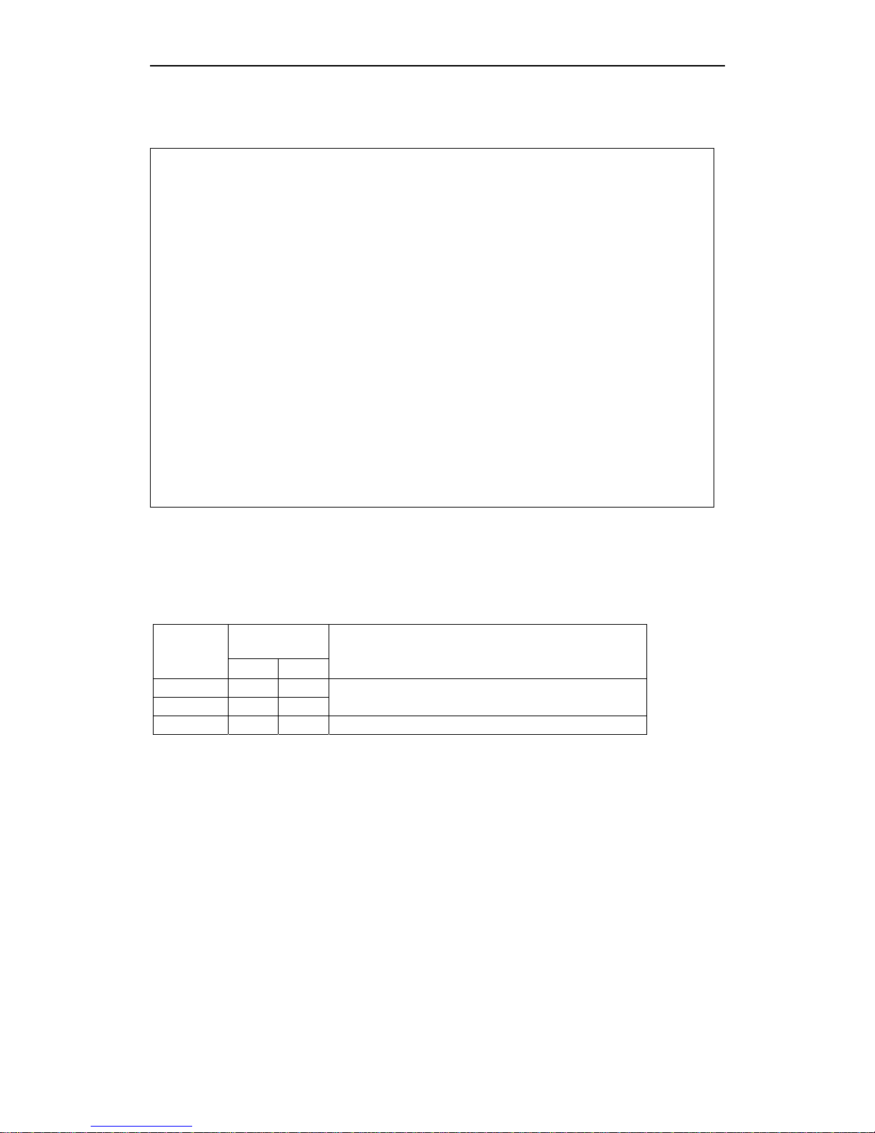
Table 2-2 Mounting Tightening Torques of SINAMICS G110
Fixing Bolt
(not supplied)
Frame Size
Size Qty
Tightening Torque of fixings
A M4 2
B M4 4
2.5 Nm (22.12 lbf.in) with washers fitted
C M5 4 4.0 Nm (35.40 lbf.in) with washers fitted
04/2005 Installation
SINAMICS G110 Operating Instructions
6SL3298-0AA11-0BP0
23
2.9 Electrical Installation
WARNING
¾ To ensure the safe operation of the equipment, it must be installed and
commissioned by qualified personnel in full compliance with the warnings laid
down in these operating instructions.
¾ Never use high voltage insulation test equipment on cables connected to the
inverter.
¾ Take particular note of the general and regional installation and safety
regulations regarding work on dangerous voltage installations (e.g. EN 50178),
as well as the relevant regulations regarding the correct use of tools and
personal protective gear.
¾ The mains input, DC and motor terminals, can carry dangerous voltages even if
the inverter is inoperative; wait 5 minutes to allow the unit to discharge after
switching off before carrying out any installation work.
¾ The inverters can be installed in a side-by-side configuration with a minimum
distance as shown in Figure 2-4 on page 22.
CAUTION
The control, power supply and motor leads must be laid separately. Do not feed
them through the same cable conduit/trunking.
2.9.1 General
WARNING
The inverter must always be grounded. If the inverter is not grounded correctly,
extremely dangerous conditions may arise within the inverter, which could prove
potentially fatal. This also applies to ungrounded IT supplies
Operation with ungrounded (IT) supplies
¾ Filtered inverters CANNOT be used on ungrounded supplies.
¾ FSA unfiltered inverter can be used on ungrounded supplies.
If an output phase is shorted to ground, the inverter may trip with F0001
(overcurrent).
¾ FSB and FSC can be used on ungrounded supplies, but it is necessary to cut
the ‘Y’ capacitor link as described in Removal of ‘Y’ Capacitor Link on page 79.
If an output phase is shorted to ground, the inverter may trip with F0001
(overcurrent).
Installation 04/2005
SINAMICS G110 Operating Instructions
24 6SL3298-0AA11-0BP0
Operation with Residual Current Device
If an RCD (also referred to as ELCB or RCCB) is fitted, the SINAMICS G110
inverters will operate without nuisance tripping, provided that:
¾ A type B RCD is used.
¾ If the SINAMICS G110 inverter is connected to a single-phase grounded-neutral
star mains network, an RCD of type A is permissible.
¾ The trip limit of the RCD is 30 mA.
¾ The neutral of the supply is grounded.
¾ Only one inverter is supplied from each RCD.
¾ The output cables are less than 25 m [82.02 ft](screened) or 50 m [164.04 ft]
(unscreened).
Operation with long cables
WARNING
Never use high voltage insulation test equipment on cables connected to the
inverter.
CAUTION
The control, power supply and motor leads must be laid separately. Do not feed
them through the same cable conduit/trunking.
All inverters will operate at full specification with the following cable lengths:
♦ 25 m (82.02 ft) [FSA filtered 10 m (32.81 ft)] screened cable
♦ 50 m (164.04 ft) unscreened cable
2.9.2 Power and motor connections
WARNING
¾ Isolate the mains electrical supply before making or changing connections to
the unit.
¾ Ensure that the inverter is connected to the correct supply voltage:
single-phase 230 V SINAMICS G110 inverters must not be connected to a
higher voltage supply.
NOTES
¾ Ensure that the appropriate circuit-breakers/fuses with the specified current
rating are connected between the power supply and inverter (see Technical
Specifications on page 67).
¾ Use Class 1 75
o
C copper wire with the cross-sections as specified in Table 7-4
and Table 7-5 on pages 68 and 69 respectively (16 AWG minimum for UL
compliance). For tightening torque see Table 7-2 on page 68.
¾ To tighten up the power terminal screws use a 4 - 5 mm cross-tip screwdriver.
¾ To conform to UL requirements the control terminals of the G110 inverter are
UL Recognized for use only with solid conductors.
¾ To conform to UL requirements a UL listed Crimp Ring Terminal should be used
on the following PE (ground) terminals of the G110 inverter: FSA – both input
and motor PE terminals. FSB and FSC – the input PE terminal only.

04/2005 Installation
SINAMICS G110 Operating Instructions
6SL3298-0AA11-0BP0
25
Access to the power and motor terminals
Figure 2-5 below show the layout of the SINAMICS G110 inverter’s control, power
and motor connection terminals.
Figure 2-5 SINAMICS G110 Connection Terminals
Figure 2-6 SINAMICS G110 DC Terminals Connections

Installation 04/2005
SINAMICS G110 Operating Instructions
26 6SL3298-0AA11-0BP0
On FSA to access the DC+/DC- terminals the cutout cover must be removed using
a small pair of cutters, ensuring that no plastics from the cutout fall into the inverter
housing (see Figure 2-6 on page 25). The terminal connection consists of two
spades measuring 6.3 mm by 0.8 mm. With the cutout cover removed and no
connections fitted to the spades, the inverter has only IP00 protection.
On FSB and FSC the DC+/DC- terminals are located on the underside at the
bottom of the unit (see Figure 2-6 on page 25). To access the DC terminals the two
upper plastic protectors (rabbits-teeth) must be removed by cutting them with a
small pair of cutters, ensure that no plastics from the protectors fall into the inverter
housing.
Connection of the DC bus between inverters is only envisaged for very basic
applications. For example, a simple winder/unwinding machine where both
inverters are powered from the same power supply and the same phase.
Caution
1. The DC+ terminal must be connected to the DC+ terminal of the other inverter
and conversely the DC- terminal must be connected to the DC- terminal of the
other inverter. Failure to connect the terminals correctly can result in severe
damage to both inverters.
2. Both inverters must be powered from the same power supply and the same
phase.
3. In the case of a short circuit on one of the inverters both inverters may be
damaged.
4. The inverters should be mounted as close as possible to reduce the length of
the DC link cables.
The following guidelines will keep the conformity of the inverter to UL requirements.
If connections to the DC Link terminals are required, then the following (or
equivalent) terminal crimps are recommended for use:
♦ Frame Size A – Molex crimp 19003-0001, Molex hand tool 19285-0036
♦ Frame Size B – Molex crimp 19017-0037, Molex hand tool 19285-0037 or
64001-0200.
♦ Frame Size C – Molex crimp 19017-0037, Molex hand tool 19285-0020 or
64001-0200.
The correct crimping tool must be used to join the crimp to the cable to ensure a
correct and secure connection.
The specified crimps and tools are readily available from any large supplier of
electrical connections. These can also be sourced by searching the Internet using
the part number specified.
The following minimum cross-section for cables should be used when utilizing the
DC terminals:
♦ FSA – 0.5 mm
2
(20 AWG)
♦ FSB – 1.5 mm
2
(16 AWG)
♦ FSC – 2.5 mm
2
(12 AWG)

04/2005 Installation
SINAMICS G110 Operating Instructions
6SL3298-0AA11-0BP0
27
Figure 2-7 Motor and Power Connections
2.9.3 Avoiding Electro-Magnetic Interference (EMI)
The inverters are designed to operate in an industrial environment where a high
level of EMI can be expected. Usually, good installation practices will ensure safe
and trouble-free operation. If you encounter problems, follow the guidelines stated
below.
Action to Take
¾ Ensure that there is a good metal-to-metal connection between the inverter and
it’s (grounded) metal mounting surface.
¾ Ensure that all equipment in the cubicle is well grounded using short, thick
grounding cable connected to a common star point or busbar
¾ Make sure that any control equipment (such as a PLC) connected to the
inverter is connected to the same ground or star point as the inverter via a short
thick link.
¾ Connect the return ground from the motors controlled by the inverters directly to
the ground connection (PE) on the associated inverter
¾ Flat grounding conductors are preferred as they have lower impedance at
higher frequencies
¾ Terminate the ends of the cable neatly, ensuring that unscreened wires are as
short as possible
¾ Separate the control cables from the power cables as much as possible, using
separate trunking, cross them if necessary at 90º to each other.
¾ Whenever possible, use screened leads for the connections to the control
circuitry
¾ Ensure that the contactors in the cubicle are suppressed, either with R-C
suppressors for AC contactors or 'flywheel' diodes for DC contactors fitted to the
coils. Varistor suppressors are also effective.
¾ Use screened or armored cables for the motor connections and ground the
screen at both ends using the cable clamps
¾ For EMC compliant installation using the DIN Rail Mounting Kit, please refer to
Appendix B on page 80.

Installation 04/2005
SINAMICS G110 Operating Instructions
28 6SL3298-0AA11-0BP0
The inverter can be screened using the methodology shown in Figure 2-8 below.
Figure 2-8 Wiring Guidelines to Minimize the Effects of EMI
Legend
1 Motor cable
2 Use suitable clips to fix motor and control cable screens securely to metal back plate
3 Mains power cable
4 Retaining screw (inverter fixing bolts)
5 Line commutating Choke
6 Control cable
 Loading...