

Page 1
www.siemens.com/drives
Reference Manual
Excitation Unit
SINAMICS DCM
Type 6RN
Tests carried out on drives
This documentation pertains to
SINAMICS DCM
F03
Edition 02/2019
Page 2

14.02.2019 15:27
V8.00
Page 3
Excitation Unit
SINAMICS DCM
Type 6RN
This documentation pertains to
SINAMICS DCM
F03
Introduction
1
Reference Manual
General scope of services
Tests
2
3
Edition 02/2019
Page 4
Legal information
Warning notice system
This manual contains notices you have to observe in order to ensure your personal safety, as well as to prevent
damage to property. The notices referring to your personal safety are highlighted in the manual by a safety alert
symbol, notices referring only to property damage have no safety alert symbol. These notices shown below are
graded according to the degree of danger.
DANGER
indicates that death or severe personal injury will result if proper precautions are not taken.
WARNING
indicates that death or severe personal injury may result if proper precautions are not taken.
CAUTION
indicates that minor personal injury can result if proper precautions are not taken.
NOTICE
indicates that property damage can result if proper precautions are not taken.
If more than one degree of danger is present, the warning notice representing the highest degree of danger will be
used. A notice warning of injury to persons with a safety alert symbol may also include a warning relating to property
damage.
Qualified Personnel
The product/system described in this documentation may be operated only by personnel qualified for the specific
task in accordance with the relevant documentation, in particular its warning notices and safety instructions. Qualified
personnel are those who, based on their training and experience, are capable of identifying risks and avoiding
potential hazards when working with these products/systems.
Proper use of Siemens products
Note the following:
WARNING
Siemens products may only be used for the applications described in the catalog and in the relevant technical
documentation. If products and components from other manufacturers are used, these must be recommended or
approved by Siemens. Proper transport, storage, installation, assembly, commissioning, operation and
maintenance are required to ensure that the products operate safely and without any problems. The permissible
ambient conditions must be complied with. The information in the relevant documentation must be observed.
Trademarks
All names identified by ® are registered trademarks of Siemens AG. The remaining trademarks in this publication
may be trademarks whose use by third parties for their own purposes could violate the rights of the owner.
Disclaimer of Liability
We have reviewed the contents of this publication to ensure consistency with the hardware and software described.
Since variance cannot be precluded entirely, we cannot guarantee full consistency. However, the information in this
publication is reviewed regularly and any necessary corrections are included in subsequent editions.
Siemens AG
Process Industries and Drives
Postfach 48 48
90026 NÜRNBERG
GERMANY
Document order number: 8888888888-000088
Ⓟ 02/2019 Subject to change
Copyright © Siemens AG 2019.
All rights reserved
Page 5

Table of contents
1 Introduction...................................................................................................................................................7
2 General scope of services ............................................................................................................................9
2.1 Routine test ............................................................................................................................11
2.2 Visual inspection ....................................................................................................................12
2.3 Function tests.........................................................................................................................13
2.4 Insulation test .........................................................................................................................14
3 Tests...........................................................................................................................................................15
3.1 Visual inspection ....................................................................................................................16
3.1.1 Rating plate............................................................................................................................16
3.1.2 Housing degree of protection.................................................................................................16
3.1.3 Electrical cabinet components ...............................................................................................17
3.1.4 Cable installation....................................................................................................................17
3.1.5 Cable markings ......................................................................................................................18
3.1.6 Setting values of circuit breakers, if used...............................................................................18
3.1.7 Dimensions ............................................................................................................................18
3.2 Function test...........................................................................................................................20
3.2.1 Connecting the excitation equipment.....................................................................................20
3.2.2 Voltage test ............................................................................................................................20
3.2.3 Current limitation test .............................................................................................................21
3.2.4 External EMERGENCY OFF..................................................................................................21
3.2.5 Temperature monitoring of the de-excitation resistor.............................................................22
Index...........................................................................................................................................................23
SINAMICS DCM 6RN F03
Reference Manual Rev.201902141527 SINAMICS DCM 5
Page 6

Table of contents
SINAMICS DCM 6RN F03
6 Reference Manual Rev.201902141527 SINAMICS DCM
Page 7

Introduction
This document describes the preconditions when testing drives. The fulfillment of these
preconditions is the basis for achieving the smoothest possible testing process and maximum
possible customer satisfaction.
The following drive tests are described:
● Routine tests
● Tests that are offered as standard
Note
If the scope of testing and inspection cannot fulfill all customer requirements, please consult
your Siemens sales advisor at head office.
1
SINAMICS DCM 6RN F03
Reference Manual Rev.201902141527 SINAMICS DCM 7
Page 8

Introduction
SINAMICS DCM 6RN F03
8 Reference Manual Rev.201902141527 SINAMICS DCM
Page 9

General scope of services
A variable-speed drive can include the following components:
● Induction motor, synchronous motor or PEM motor with or without speed encoder
● SINAMICS drives
● Drive transformer
● Cooling unit for water-cooled drives
● Small PLCs with drive functionality.
The Nuremberg Vogelweiherstrasse factory offers test equipment adapted to these types of
systems.
Note
Contact your sales person if additional components must be taken into account for your
particular project.
Scope of services offered
2
Unless otherwise stated in the quotation, the scope of services includes all activities,
equipment, materials and expendables required to perform the specified tests. The deadline
and testing period stated, and the quoted cost, can be met only if all the test and inspection
procedures to be performed are clarified in detail in advance. Due to the high capacity utilization
of the associated equipment, it might not be possible to carry out individual inspections and
tests that are requested late if the planned test is already in progress.
If you have received specific requirements from your customer, please send these as soon as
possible – with the necessary key data – to the Nuremberg Vogelweiherstrasse factory.
Sequence of a customer acceptance
A customer acceptance test is generally executed in the sequence:
1. Installation and commissioning of the components before the customer arrives.
2. Kickoff with presentation of the test schedule and discussion of individual steps in the
acceptance test workflow.
3. Execution of the tests according to the test schedule
4. Discussion of the test results
5. Preparation of test documentation for the customer.
The test documentation is created before or after the customer leaves depending on the
scope of testing and the time schedule.
SINAMICS DCM 6RN F03
Reference Manual Rev.201902141527 SINAMICS DCM 9
Page 10

General scope of services
Components provided by customer
Components provided by the customer must be available in plenty of time so that tests can be
carried out on time. The Nuremberg Vogelweiherstrasse factory has no access to components
that are not within the PD LD scope of supply. This also applies to components ordered from
other Siemens' Groups. The technical data for these components is required at the latest eight
weeks before the start of the acceptance test, e.g.:
● Dimensions
● Weights
● Energy Requirement
● Interfaces
Location of the customer acceptance
All customer acceptance tests in the test fields for drives are performed as part of the
manufacturing process.
Note
Limited number of persons in the test field
For safety reasons, the number of persons in the test field is limited. In addition to the regional
sales partner, only two persons from the customer are permitted in the test field at the same
time.
Note
Test without load motors or multipulse infeeds via transformers in the test field
Some tests are simulated or performed in test mode with limited rated data.
Note
Tests with the customer's own cooling units or excitation equipment
If the customer's own cooling units or excitation equipment are to be tested, a system test can
be ordered with option F97.
SINAMICS DCM 6RN F03
10 Reference Manual Rev.201902141527 SINAMICS DCM
Page 11

2.1 Routine test
During production, the drive is subject to an internal routine test.
General scope of services
2.1 Routine test
SINAMICS DCM 6RN F03
Reference Manual Rev.201902141527 SINAMICS DCM 11
Page 12
General scope of services
2.2 Visual inspection
2.2 Visual inspection
The visual inspection is performed to ensure that the equipment complies with the order
specifications. The tests are carried out with the drive in a no-voltage condition.
The visual inspection together with the customer – or with the company accepting the
equipment – is carried out with the drive installed and labeled. Each test step is documented in
the acceptance report with the specific results of the step.
The visual inspection is part of the function test (F72, F73).
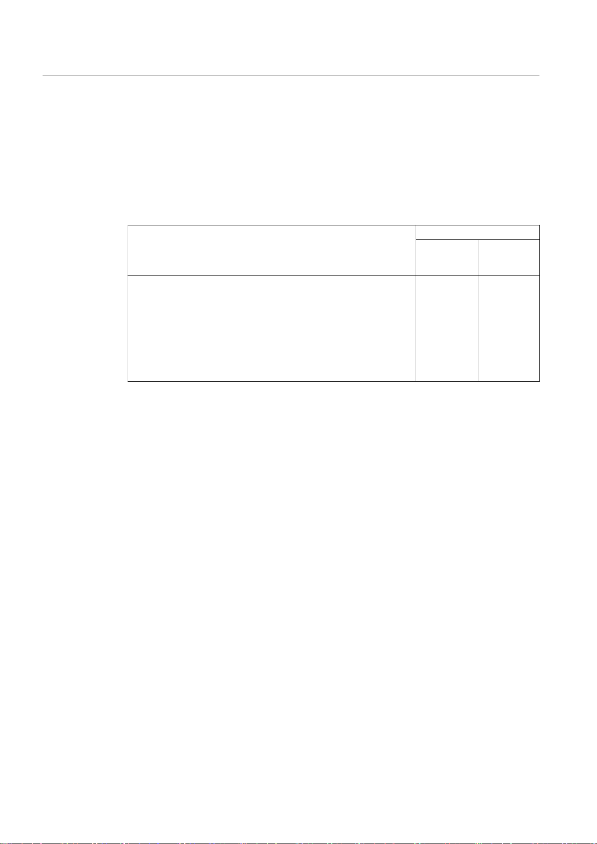
Visual inspection Order codes
● Rating plate
● Housing degree of protection
● Electrical cabinet components
● Cable installation
● Cable markings
● Setting values of circuit breakers, if used
● Dimensions
Without the
customer
present
-
With the cus‐
tomer
present
F03
See also
Visual inspection (Page 16)
SINAMICS DCM 6RN F03
12 Reference Manual Rev.201902141527 SINAMICS DCM
Page 13

2.3 Function tests
The drive functions are tested according to IEC 61800-5-1. In addition, excerpts from additional
standards apply, which are listed in the relevant chapters as well as internal Siemens directives
within the scope of quality assurance.
The function tests are performed and documented in the Siemens test field by internal test field
personnel. For the function test, the drive is in the test mode with restricted monitoring functions.
The successful test is confirmed in a 3.1 certificate – or in the case that the customer has
ordered the acceptance test, in a 3.2 certificate.
See also
Function test (Page 20)
General scope of services
2.3 Function tests
SINAMICS DCM 6RN F03
Reference Manual Rev.201902141527 SINAMICS DCM 13
Page 14
General scope of services
2.4 Insulation test
2.4 Insulation test
The insulation resistance is measured before and after the high-voltage test. The insulation test
can only be ordered and carried out together with the function test (F72, F73).
Insulation test Order codes
● High-voltage test
● Measuring the insulation resistance
The successful test is confirmed in a 3.1 certificate – or in the case that the customer has
ordered the acceptance test, in a 3.2 certificate.
The insulation test is performed on a separate acceptance day prior to the function test.
Without the
customer
present
F76
With the cus‐
tomer
present
F77
SINAMICS DCM 6RN F03
14 Reference Manual Rev.201902141527 SINAMICS DCM
Page 15

Tests
3
The tests that have been expressly ordered for the drive with serial number K91539032021001
are listed in the following.
SINAMICS DCM 6RN F03
Reference Manual Rev.201902141527 SINAMICS DCM 15
Page 16

Tests
3.1 Visual inspection
3.1 Visual inspection
The visual inspection is performed to ensure that the drive complies with the requirements of
the order. The individual test steps are performed with the drive in a no-voltage condition.
The test together with the customer – or his representative – is carried out with the drive
installed and labeled. The results of all of the tests are documented in the acceptance report.
3.1.1 Rating plate
Fundamentals
The technical data and ordered options on the rating plate and the routine test certificate are
checked to ensure that they match up.
Test procedure
1. The data on the rating plate and the routine test certificate are visually compared.
Result
The test is passed if the data match up.
3.1.2 Housing degree of protection
Fundamentals
A check is made as to whether the housing degree of protection ordered complies with what is
described in the catalog.
Test procedure
1. The housing degree of protection is identified based on what is stamped on the rating plate.
2. Depending on the version, the following components are visually checked, e.g.:
– Canopies
– Cooling slots
– Fittings and rubber seals in the doors and between the cabinet units
– Cable entries
– Openings for water pipes, if available
– Additional components, if available
SINAMICS DCM 6RN F03
16 Reference Manual Rev.201902141527 SINAMICS DCM
Page 17

Result
The test is passed if the components required for the specified housing degree of protection are
available.
3.1.3 Electrical cabinet components
Fundamentals
A visual inspection is made to see whether the electrical cabinet components are installed as
defined in the layout diagram and/or circuit diagram.
Test procedure
1. The customer selects electrical cabinet components by random sampling.
2. The selected electrical cabinet components are visually checked to ensure that they are
correctly installed and marked.
Tests
3.1 Visual inspection
Result
The test is passed if the selected electrical cabinet components are installed as specified in the
layout diagram and/or circuit diagram.
3.1.4 Cable installation
Fundamentals
Visual and mechanical checks are made to ensure that cables and conductors have been
installed correctly and are connected correctly according to the circuit diagram.
Test procedure
1. The customer selects cables or conductors by random sampling.
2. The following is inspected:
– Are the cables firmly connected?
– Have edge protectors been attached to sharp edges?
– Are the cables routed according to the circuit diagram?
Result
The inspection is passed if the cable installation does not exhibit any deficiencies and matches
the information in the circuit diagram.
SINAMICS DCM 6RN F03
Reference Manual Rev.201902141527 SINAMICS DCM 17
Page 18

Tests
3.1 Visual inspection
3.1.5 Cable markings
Fundamentals
A visual inspection is made to see whether cables and conductors are marked as defined in the
circuit diagram.
Test procedure
1. The customer selects cables or conductors by random sampling.
– Are the cable end tags and conductor colors of cables and conductors marked as defined
in the circuit diagram?
Result
The test is passed if the cable and conductor markings match what is specified in the circuit
diagram.
3.1.6 Setting values of circuit breakers, if used
Fundamentals
The circuit breaker settings are visually checked against what is specified in the circuit diagram.
Test procedure
1. The customer selects circuit breakers by random sampling.
2. The circuit breaker settings are visually checked against what is specified in the circuit
diagram.
Result
The test is passed if the circuit breaker settings match what is specified in the circuit diagram.
3.1.7 Dimensions
Fundamentals
The drive dimensions are measured. The basis for the visual inspection is the order-specific
dimension drawing.
Test procedure
1. The external dimensions, length, width and height of the drive are measured.
SINAMICS DCM 6RN F03
18 Reference Manual Rev.201902141527 SINAMICS DCM
Page 19

Result
Tests
3.1 Visual inspection
The test is passed if the dimensions match with what is specified in the dimension drawing.
SINAMICS DCM 6RN F03
Reference Manual Rev.201902141527 SINAMICS DCM 19
Page 20

Tests
3.2 Function test
3.2 Function test
3.2.1 Connecting the excitation equipment
Fundamentals
A check is made as to whether the PROFIBUS connection to the DC master of the excitation
equipment is established using the operating software at the test field computer. This is the
basis for additional tests and successful commissioning.
Test procedure
1. The excitation equipment is switched on.
2. The operating software has started and is connected to the excitation equipment.
3. The PROFIBUS connection is parameterized.
The operating software visualizes the status feedback signals.
Parameters can be entered.
Result
The test is successfully completed if the operating software indicates that the excitation
equipment is "Online".
3.2.2 Voltage test
Fundamentals
As no motor is available in the test station, the correct functioning of the excitation equipment
is demonstrated using an ohmic (resistive) load.
Test procedure
1. The supply voltage stamped on the nameplate is connected at the excitation equipment
input.
2. An ohmic (resistive) load is connected at the excitation unit output.
3. The excitation unit is switched on, started and operated at the rated voltage with reduced
current.
The actual electrical values are displayed on the measuring instrument/the test station
computer.
Result
The test is successfully passed if the characteristic of the armature current and voltage
corresponds to the defined curve characteristics. The displays of calibrated measuring
instruments serve as reference.
SINAMICS DCM 6RN F03
20 Reference Manual Rev.201902141527 SINAMICS DCM
Page 21

3.2.3 Current limitation test
Fundamentals
A check is made as to whether the excitation equipment limits the armature current to the
specified current. Prerequisite is a successful voltage test. The value for the momentary
armature current is available.
Test procedure
1. The excitation equipment is ready to start.
2. The current limitation parameter is reduced with the operating software.
3. The excitation system is switched on.
The armature current adjusts itself to the set current limiting value.
Result
The test is successfully passed if the armature current corresponds to the value of the set
current limitation.
Tests
3.2 Function test
3.2.4 External EMERGENCY OFF
Fundamentals
The external EMERGENCY OFF is simulated. This checks that in the case of an EMERGENCY
OFF command the excitation equipment no longer provides a voltage.
Test procedure
1. The auxiliary voltage is present.
2. To simulate an external EMERGENCY OFF, the jumper for the Emergency Stop is opened
at the appropriate terminal as shown in the circuit diagram.
The excitation equipment displays "10.x".
The operating software displays "Emergency Stop/Safety shutdown".
3. The jumper for the Emergency Stop is reconnected at the terminal.
The excitation equipment displays "7.x" or 8.x (=" Ready to switch on").
The operating software displays "Ready to switch on".
Result
The test is successfully passed if the appropriate messages are displayed.
SINAMICS DCM 6RN F03
Reference Manual Rev.201902141527 SINAMICS DCM 21
Page 22

Tests
3.2 Function test
3.2.5 Temperature monitoring of the de-excitation resistor
Fundamentals
The temperature monitoring of the de-excitation resistor is tested. This ensures that the de-
excitation resistor does not overheat in operation.
Test procedure
1. The auxiliary voltage is present.
2. To simulate the temperature monitoring, the appropriate plug connector is withdrawn as
shown in the circuit diagram.
The excitation equipment displays "10.x".
The operating software displays "Emergency Stop/Safety shutdown".
3. The temperature monitoring plug connector is reinserted.
The excitation equipment displays "7.x" or 8.x (=" Ready to switch on").
The operating software displays "Ready to switch on".
Result
The test is successfully passed if the appropriate messages are displayed.
SINAMICS DCM 6RN F03
22 Reference Manual Rev.201902141527 SINAMICS DCM
Page 23

Index
C
Components provided by customer, 10
Customer acceptance inspection, 9
F
F03, 12
F76, 14
F77, 14
Function check
Connecting the excitation equipment, 20
Current limitation test, 21
External EMERGENCY OFF, 21
Temperature monitoring of the de-excitation
resistor, 22
Voltage test, 20
Function tests, 13
I
Insulation test, 14
V
Visual inspection, 12, 16
Cable installation, 17
Cable markings, 18
Dimensions, 18
Electrical cabinet components, 17
Housing degree of protection, 16
Rating plate, 16
Setting values of circuit breakers, if used, 18
SINAMICS DCM 6RN F03
Reference Manual Rev.201902141527 SINAMICS DCM 23
Page 24

Index
SINAMICS DCM 6RN F03
24 Reference Manual Rev.201902141527 SINAMICS DCM
Page 25

Page 26

Further Information
www.siemens.com/drives
Siemens AG
Process Industries and Drives
Postfach 48 48
90026 NÜRNBERG
GERMANY
8888888888 000088 01 EN 01
*888888888800008801EN01*
888888888800008801EN01
Page 27
Process Industries and Drives
Siemens AG, PD LD P MF-NMA EN, Postfach 47 43, 90025 Nürnberg
Our ref. 8888888888000088
Date 14.02.2019
Documentation for 6RN
Your order no. - 000010
AL: N ECCN: N UL: DE
StWanr (CD): 85234045, StWanr (Print): 49011000
Dear Sir / Madam,
Many thanks for your order, the documentation for which is enclosed.
m
Yours very truly,
*888888888800008801EN01*
Page 28

Page 29

Spine label for binder 50 mm (120 g/m2)
SINAMICS DCM
6RN
SINAMICS DCM
F03
Tests carried out on drives
Spine label for binder 162 mm (120 g/m2)
SINAMICS DCM 6RN
SINAMICS DCM
F03
Tests carried out on drives
Page 30

 Loading...