

Page 1
_
_
_
_
_
_
_
_
_
_
_
_
_
_
_
_
_
_
SIMOTION D410-2
SIMOTION
SIMOTION D410-2
Manual
_________________
Preface
_________________
Description
_________________
Operator control (hardware)
_________________
Interfaces
_________________
Technical data
_________________
Dimension drawings
_________________
Spare parts / accessories
_________________
Standards and approvals
_________________
ESD guidelines
1
2
3
4
5
6
A
B
Valid for SIMOTION D410-2 DP
02/2012
Page 2
Legal information
Legal information
Warning notice system
This manual contains notices you have to observe in order to ensure your personal safety, as well as to prevent
damage to property. The notices referring to your personal safety are highlighted in the manual by a safety alert
symbol, notices referring only to property damage have no safety alert symbol. These notices shown below are
graded according to the degree of danger.
DANGER
indicates that death or severe personal injury will result if proper precautions are not taken.
WARNING
indicates that death or severe personal injury may result if proper precautions are not taken.
CAUTION
with a safety alert symbol, indicates that minor personal injury can result if proper precautions are not taken.
CAUTION
without a safety alert symbol, indicates that property damage can result if proper precautions are not taken.
NOTICE
indicates that an unintended result or situation can occur if the relevant information is not taken into account.
If more than one degree of danger is present, the warning notice representing the highest degree of danger will
be used. A notice warning of injury to persons with a safety alert symbol may also include a warning relating to
property damage.
Qualified Personnel
The product/system described in this documentation may be operated only by personnel qualified for the specific
task in accordance with the relevant documentation, in particular its warning notices and safety instructions.
Qualified personnel are those who, based on their training and experience, are capable of identifying risks and
avoiding potential hazards when working with these products/systems.
Proper use of Siemens products
Note the following:
WARNING
Siemens products may only be used for the applications described in the catalog and in the relevant technical
documentation. If products and components from other manufacturers are used, these must be recommended
or approved by Siemens. Proper transport, storage, installation, assembly, commissioning, operation and
maintenance are required to ensure that the products operate safely and without any problems. The permissible
ambient conditions must be complied with. The information in the relevant documentation must be observed.
Trademarks
All names identified by ® are registered trademarks of Siemens AG. The remaining trademarks in this publication
may be trademarks whose use by third parties for their own purposes could violate the rights of the owner.
Disclaimer of Liability
We have reviewed the contents of this publication to ensure consistency with the hardware and software
described. Since variance cannot be precluded entirely, we cannot guarantee full consistency. However, the
information in this publication is reviewed regularly and any necessary corrections are included in subsequent
editions.
Siemens AG
Industry Sector
Postfach 48 48
90026 NÜRNBERG
GERMANY
Copyright © Siemens AG 2012.
All rights reserved
Page 3

Preface
Contents of the Product Manual
This document is part of the SIMOTION D documentation package.
Scope
The SIMOTION D410-2 Manual describes the SIMOTION D410-2 DP Control Unit.
Note
An independent SIMOTION D410 Manual is available for the SIMOTION D410 DP and
SIMOTION D410 PN Control Units.
Standards
The SIMOTION system was developed in accordance with ISO 9001 quality guidelines.
Sections in this manual
The following information blocks describe of the purpose and the use of the manual:
● Description
This section provides information pertaining to the SIMOTION system and its integration
in the information landscape.
● Operator control (hardware)
This section describes the operator control and display elements of the SIMOTION D410-
2.
● Interfaces
This section provides information on the interfaces, their pin assignments and application
options.
● Technical data
This section describes the properties and features of the SIMOTION D410-2.
● Dimension drawings
● Spare parts / accessories
SIMOTION D410-2
Manual, 02/2012
This section provides information about accessories and spare parts for the
SIMOTION D410-2.
3
Page 4

Preface
● Appendix
This section provides information about the various standards, approvals and EMC
directives that the device complies with.
● Index to locate information
SIMOTION Documentation
An overview of the SIMOTION documentation can be found in a separate list of references.
This documentation is included as electronic documentation in the scope of delivery of
SIMOTION SCOUT. It comprises 10 documentation packages.
The following documentation packages are available for SIMOTION V4.3:
● SIMOTION Engineering System
● SIMOTION System and Function Descriptions
● SIMOTION Service and Diagnostics
● SIMOTION IT
● SIMOTION Programming
● SIMOTION Programming - References
● SIMOTION C
● SIMOTION P
● SIMOTION D
● SIMOTION Supplementary Documentation
Additional information
Click the following link to find information on the the following topics:
● Ordering documentation/overview of documentation
● Additional links to download documents
● Using documentation online (find and search in manuals/information)
http://www.siemens.com/motioncontrol/docu
Please send any questions about the technical documentation (e.g. suggestions for
improvement, corrections) to the following e-mail address:
[email protected]
My Documentation Manager
Click the following link for information on how to compile documentation individually on the
basis of Siemens content and how to adapt this for the purpose of your own machine
documentation:
http://www.siemens.com/mdm
SIMOTION D410-2
4 Manual, 02/2012
Page 5

Preface
Training
Click the following link for information on SITRAIN - Siemens training courses for automation
products, systems and solutions:
http://www.siemens.com/sitrain
FAQs
Frequently Asked Questions can be found in SIMOTION Utilities & Applications, which are
included in the scope of delivery of SIMOTION SCOUT, and in the Service&Support pages
in Product Support:
http://support.automation.siemens.com
Technical support
Country-specific telephone numbers for technical support are provided on the Internet under
Contact:
http://www.siemens.com/automation/service&support
Disposal and recycling
SIMOTION D410-2 is an environmentally friendly product! It includes the following features:
● In spite of its excellent resistance to fire, the flame-resistant agent in the plastic used for
the housing does not contain halogens.
● Identification of plastic materials in accordance with ISO 11469.
● Less material used because the unit is smaller and with fewer components thanks to
integration in ASICs.
The disposal of the products described in this manual should be performed in compliance
with the valid national regulations.
The products can be largely recycled owing to their low pollutant content. To recycle and
dispose of your old device in an environmentally friendly way, please contact a recycling
company certified for electronic waste.
If you have any further questions about disposal and recycling, please contact your local
Siemens representative. Contact details can be found in our contacts database on the
Internet at:
http://www.automation.siemens.com/partner
SIMOTION D410-2
Manual, 02/2012
5
Page 6

Preface
Further information / FAQs
You can find further information on this manual under the following FAQ:
http://support.automation.siemens.com/WW/view/de/27585482
The following information sources are also available:
● SIMOTION Utilities & Applications: SIMOTION Utilities & Applications will be included in
the SIMOTION SCOUT scope of delivery and, along with FAQs, also contain free utilities
(e.g. calculation tools, optimization tools, etc.) as well as application examples (ready-toapply solutions such as winders, cross cutters or handling)
● The latest SIMOTION FAQs at
http://support.automation.siemens.com/WW/view/en/10805436/133000
● SIMOTION SCOUT online help
● For additional documentation (separate document), please refer to the list of references
SIMOTION D410-2
6 Manual, 02/2012
Page 7

Table of contents
Preface ...................................................................................................................................................... 3
1
Description................................................................................................................................................. 9
1.1
1.2
1.3
1.4
1.5
1.6
1.7
1.8
2
Operator control (hardware)..................................................................................................................... 25
2.1
2.2
2.2.1
2.2.2
2.2.3
2.2.4
2.2.5
2.2.6
2.3
3
Interfaces................................................................................................................................................. 33
System overview............................................................................................................................9
System components ....................................................................................................................13
I/O integration...............................................................................................................................17
SIMOTION D410-2 DP representation ........................................................................................18
Type plates...................................................................................................................................19
CompactFlash card......................................................................................................................20
Licensing......................................................................................................................................23
Safety information ........................................................................................................................24
Overview of operator control and display elements.....................................................................25
Operator controls .........................................................................................................................26
Service selector switch ................................................................................................................26
Mode selector switch ...................................................................................................................27
DIAG button .................................................................................................................................29
RESET button ..............................................................................................................................30
Switch S5.0 ..................................................................................................................................30
SIMOTION CompactFlash card...................................................................................................31
Error and status displays .............................................................................................................32
3.1
3.2
3.3
3.4
3.5
3.5.1
3.5.2
3.5.3
3.5.4
3.5.5
3.6
3.7
3.8
3.9
SIMOTION D410-2
Manual, 02/2012
Overview of interfaces .................................................................................................................33
DRIVE-CLiQ interface..................................................................................................................34
PROFIBUS DP interfaces............................................................................................................36
Encoder interface (HTL/TTL/SSI) ................................................................................................38
Digital I/Os / temperature sensor / analog input ..........................................................................41
Properties.....................................................................................................................................41
Interface characteristics ...............................................................................................................42
Interface assignment....................................................................................................................42
Use of the interfaces ....................................................................................................................47
Connection examples ..................................................................................................................49
Power supply................................................................................................................................54
Ethernet interface.........................................................................................................................55
Measuring sockets .......................................................................................................................57
Power Module Interface...............................................................................................................58
7
Page 8

Table of contents
4 Technical data ......................................................................................................................................... 59
4.1 Shipping and storage conditions................................................................................................. 59
4.2
4.3
4.4
4.4.1
4.4.2
4.4.3
4.4.4
4.5
5
Dimension drawings ................................................................................................................................ 71
5.1
5.2
5.3
6
Spare parts / accessories ........................................................................................................................ 75
6.1
6.2
6.3
6.4
6.5
Mechanical and climatic ambient conditions............................................................................... 60
System data, connection values, dimensions and weight .......................................................... 62
Interfaces and performance features .......................................................................................... 63
PLC and motion control performance ......................................................................................... 63
Communication ........................................................................................................................... 64
Onboard I/Os............................................................................................................................... 65
Onboard encoder interface ......................................................................................................... 67
Clock ........................................................................................................................................... 68
SIMOTION D410-2 DP dimension drawing ................................................................................ 71
Mounting plate dimension drawing ............................................................................................. 72
CAD data, dimension drawings, and circuit-diagram macros..................................................... 73
Available spare parts and accessories ....................................................................................... 75
TM31 terminal module ................................................................................................................ 77
TM41 terminal module ................................................................................................................ 78
TM54F terminal module .............................................................................................................. 78
TM15 and TM17 High Feature terminal modules ....................................................................... 80
6.6
6.7
A
Standards and approvals......................................................................................................................... 83
A.1
A.2
A.3
B
ESD guidelines ........................................................................................................................................ 87
B.1
B.2
B.3
Index........................................................................................................................................................ 91
CUA31/CUA32 control unit adapter............................................................................................ 81
DMC20/DME20 DRIVE-CLiQ hub .............................................................................................. 82
General rules............................................................................................................................... 83
Device-specific information ......................................................................................................... 85
Safety of electronic controllers.................................................................................................... 85
ESD definition ............................................................................................................................. 87
Electrostatic charging of individuals............................................................................................ 88
Basic measures for protection against discharge of static electricity ......................................... 89
SIMOTION D410-2
8 Manual, 02/2012
Page 9
Description
1.1 System overview
SIMOTION D
SIMOTION D is a drive-based version of SIMOTION based on the SINAMICS S120 drive
family.
With SIMOTION D, the SIMOTION PLC and motion control functionalities as well as the
SINAMICS S120 drive software run on shared control hardware.
SIMOTION D is available in two versions:
● SIMOTION D410-2 is a compact control unit predestined for single-axis applications.
● SIMOTION D4x5-2 is a control unit for multi-axis applications in the SINAMICS S120
booksize format.
The following performance variants of the SIMOTION D4x5-2 control units are offered:
Control unit Performance variant Range of applications
SIMOTION D425-2 BASIC performance For up to 16 axes
SIMOTION D435-2 STANDARD performance For up to 32 axes
SIMOTION D445-2 HIGH performance For up to 64 axes
SIMOTION D455-2 ULTRA-HIGH performance For up to 128 axes or applications with very
1
short control cycles
SIMOTION D410-2
Manual, 02/2012
Note
The SIMOTION D410-2 is described in this manual.
Separate manuals are available for the SIMOTION D4x5-2 and the SIMOTION D4x5 and
SIMOTION D410 predecessor modules.
SIMOTION D is an integral part of the Totally Integrated Automation (TIA) concept. TIA is
characterized by integrated data management, configuration, and communication for all
products and systems. Thus, an extensive toolbox of automation modules is also available
for the SIMOTION D410-2.
9
Page 10
Description
1.1 System overview
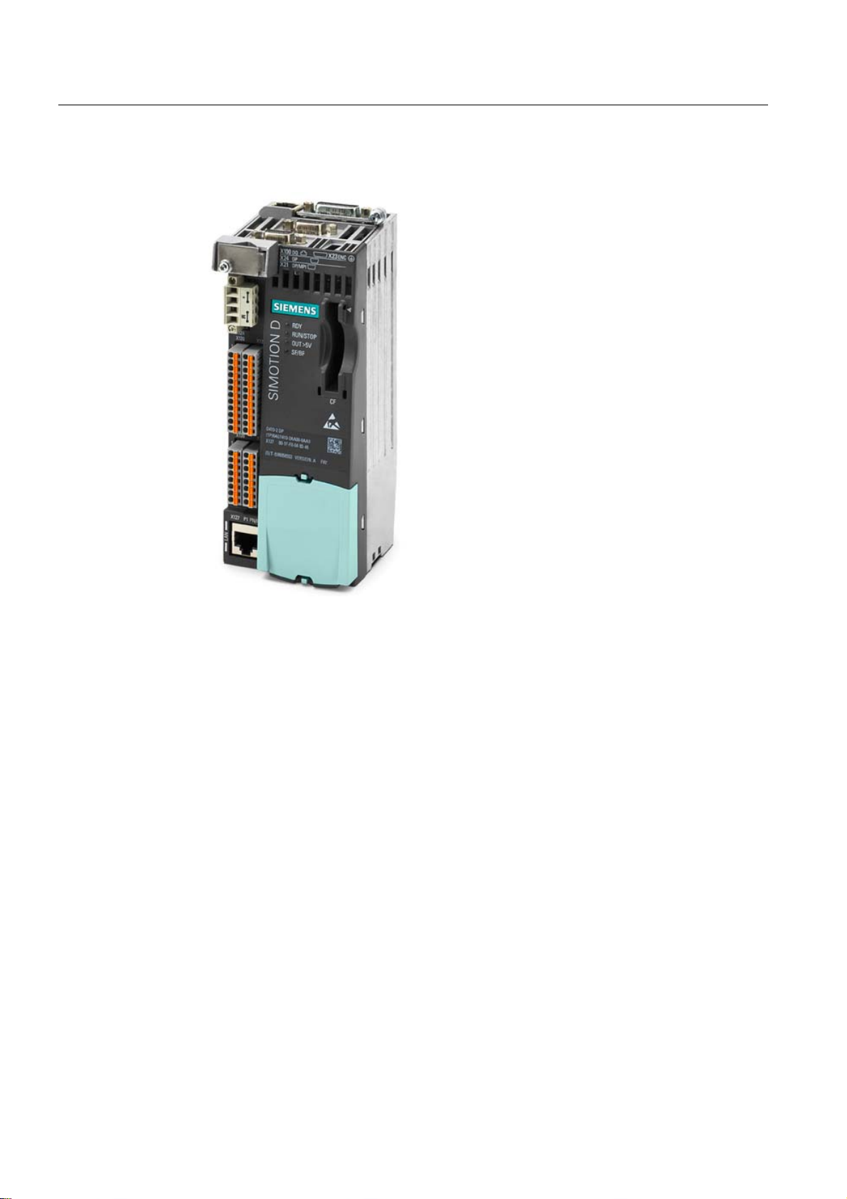
SIMOTION D410-2
Figure 1-1 SIMOTION D410-2
SIMOTION D410-2 is a compact control unit for single-axis applications.
The control unit is snapped directly on to the SINAMICS S120 PM340 power module in
blocksize format and has an integrated drive control for either one servo, one vector or one
V/f axis.
SIMOTION D410-2 can be extended with additional SINAMICS S110/S120 control units (e.g.
CU305) and so can also be used for smaller multi-axis applications (e.g. with 2 - 3 axes).
SIMOTION D410-2
10 Manual, 02/2012
Page 11
Description
1.1 System overview
Example of a single-axis application
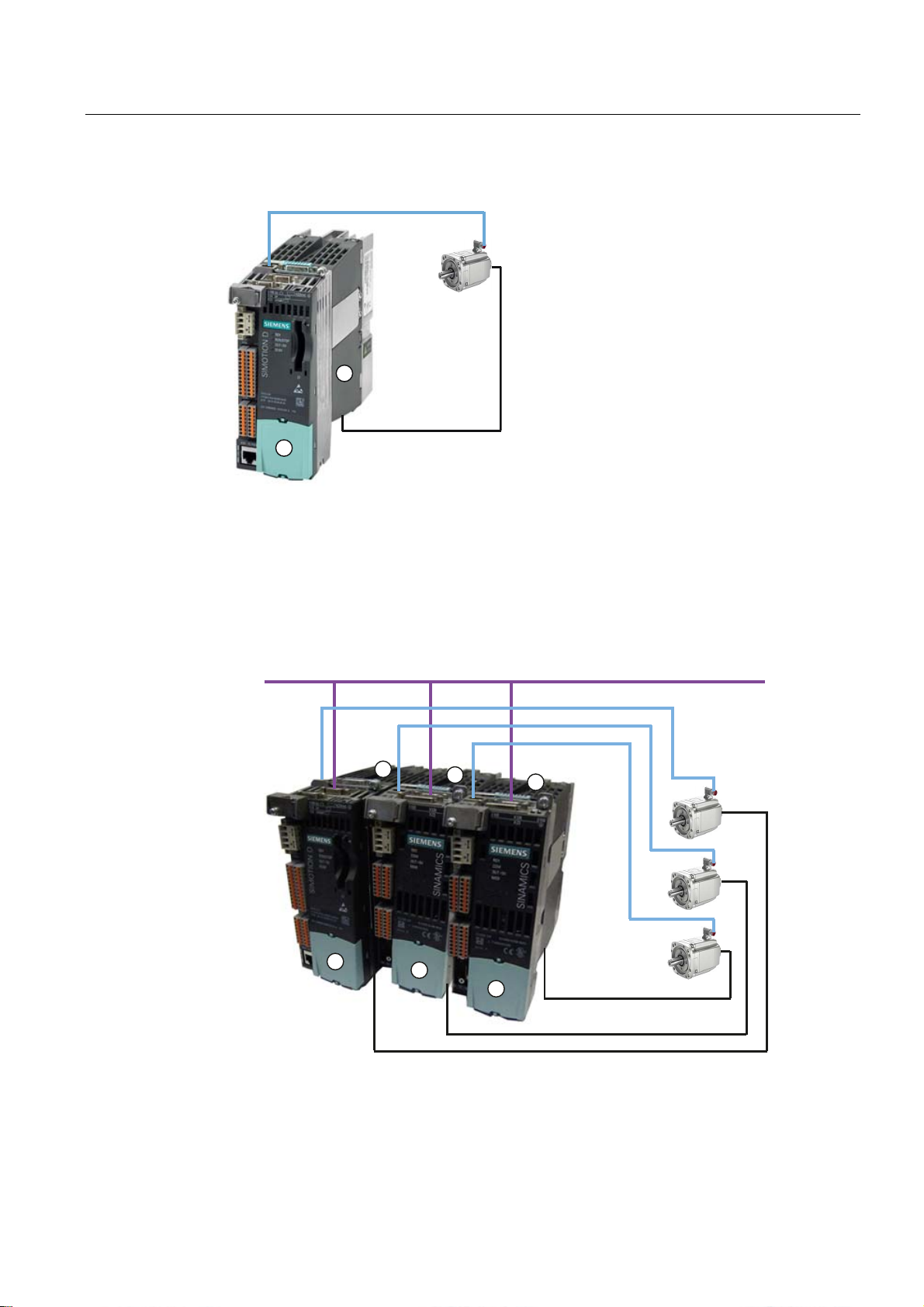
'5,9(&/L4
Figure 1-2 Application example with one axis
The example shows a single-axis application, consisting of a SIMOTION D410-2 (control
① that is snapped directly on to the SINAMICS PM340 power module ②. The motor is
unit)
supplied with power via the PM340. The encoder is connected by means of DRIVE-CLiQ.
Example of a multi-axis application
352),%86'3
3RZHU
'5,9(&/L4
SIMOTION D410-2
Manual, 02/2012
Figure 1-3 Application example with three axes
3RZHU
11
Page 12

Description
1.1 System overview
The example shows an application with three axes, consisting of:
Application
● One SIMOTION D410-2 DP (control unit)
①, snapped on to the PM340 ③
The SIMOTION D410-2 DP is snapped directly on to the SINAMICS PM340 power
module. The motor is supplied with power via the PM340. The encoder is connected by
means of DRIVE-CLiQ.
● Two SINAMICS S110 CU305
②, snapped on to the PM340 ③
The control units are connected to the SIMOTION D410-2 DP via PROFIBUS DP. The
two SINAMICS S110 CU305 are snapped directly on to the SINAMICS PM340 power
modules. The motors are supplied with power via the PM340. The encoders are
connected by means of DRIVE-CLiQ.
Note
Path interpolation is not supported for V4.3.
Combining a power module with SIMOTION D410-2 forms a compact single drive for
machine and plant engineering.
Applications include:
● Machine concepts with central drive (e.g. presses, printing and packaging machines, etc.)
● Modular machine concepts where the machine modules broken down to single axes
● Single drives with high accuracy, stability and concentricity requirements (compared with
standard drives) in machine and industrial plant engineering
● Single drives for transport tasks (conveying, raising, lowering)
● Single drives with integrated PLC functionality and expanded motion control functionality
such as output cams or cams
● Drives without power recovery (wire drawing, extruding)
● Drive connections with high availability requirements (incoming supply failure may not
cause all axes to fail)
● Small multi-axis groupings (typically two to three axes) based on SINAMICS S110/120
blocksize.
Hardware components
As central hardware the SIMOTION D410-2 control unit is made up of the SIMOTION
runtime system and the SINAMICS drive control.
A range of additional SINAMICS S120 components, such as SMx encoder systems or
terminal modules can be connected via DRIVE-CLiQ.
With a few exceptions (e.g. no BOP20 basic operator panel, etc.), the drive control
integrated in SIMOTION D410-2 has the same control properties and performance features
as the SINAMICS S120 CU310-2 control unit.
SIMOTION D410-2
12 Manual, 02/2012
Page 13

Description
1.2 System components
Extension of the drive computing performance
To fully utilize the motion control performance of a SIMOTION D410-2 when required, the
drive-side computing performance can be extended by connecting additional SINAMICS
S110/S120 control units (e.g. CU305, CU310-2, etc.) via PROFIBUS to the SIMOTION
D410-2.
Software components
The basic functionality of SIMOTION D is supplied on a CompactFlash Card containing the
following:
● The SIMOTION runtime system with the following functions:
– Freely programmable runtime system (IEC 61131)
– Various runtime levels (tasks)
– PLC and arithmetic functionality
– Motion control functions
– Communication functions
● The SINAMICS S120 drive control with the following functions:
– Current and torque control
– Speed control
1.2 System components
Overview
SIMOTION D410-2 communicates with the components of the automation landscape via the
following interfaces:
● PROFIBUS DP
● Ethernet
● DRIVE-CLiQ (DRIVE Component Link with IQ)
● Power module interface (PM-IF)
SIMOTION D features a SINAMICS Integrated drive element. Communication with the
SINAMICS Integrated is via PROFIBUS mechanisms (DP Integrated), via PROFIdrive
message frames.
Shorter cycle times and greater numbers of addresses for each node are achieved with the
"DP Integrated" compared to the "external PROFIBUS DP".
SIMOTION D410-2
Manual, 02/2012
The most important components of the system and their functions are shown below.
13
Page 14
Description
1.2 System components
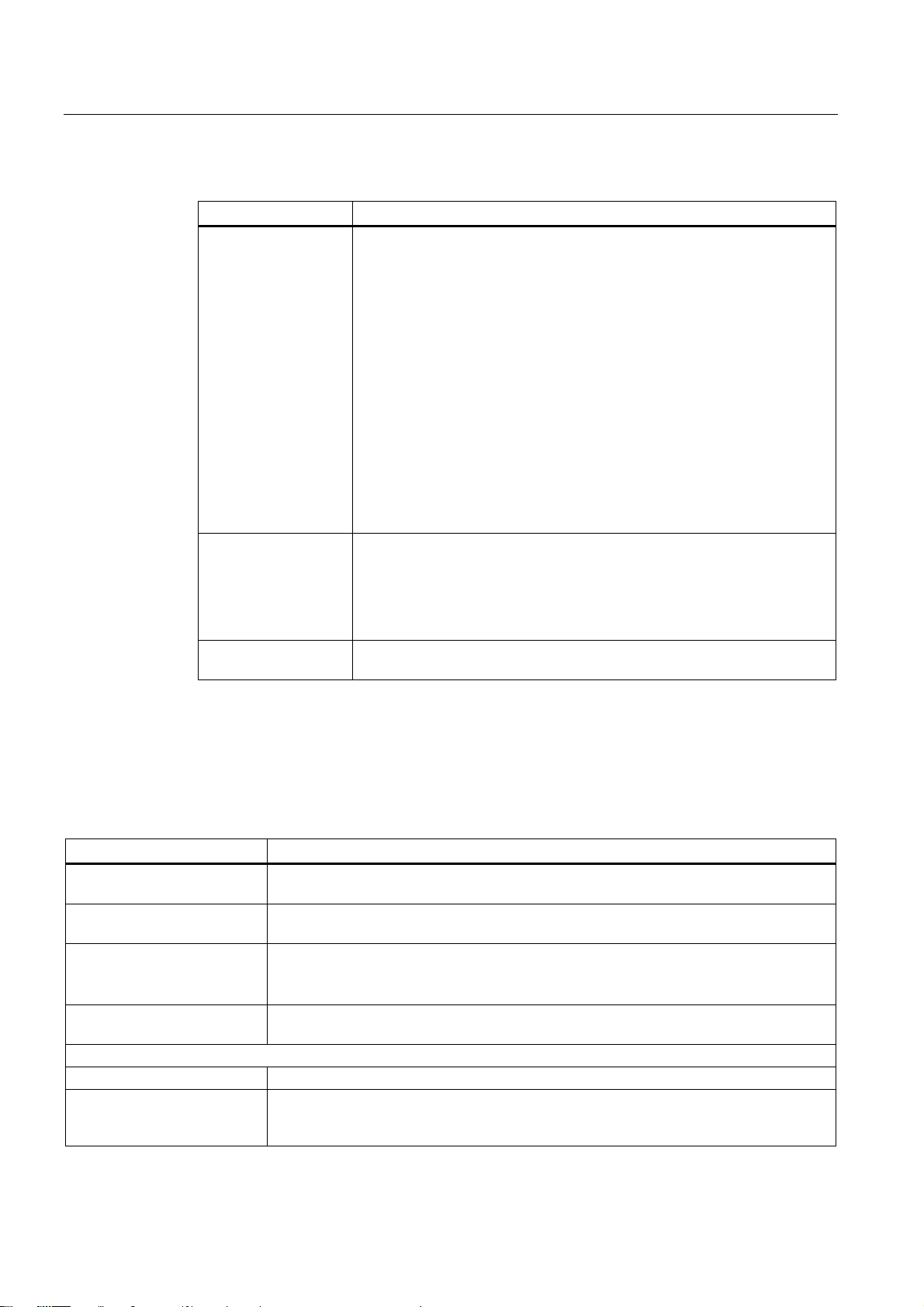
Table 1- 1 System components
Component Function
SIMOTION D410-2 ... is the central motion control module.
The module contains the programmable SIMOTION runtime of
SIMOTION D410-2 and the SINAMICS S120 drive software.
You can use the integrated high-speed I/Os (onboard I/Os) as:
• User-addressable process I/Os
• Homing inputs
• Fail-safe digital inputs
• Fail-safe digital output
• Inputs for measuring inputs
• Outputs for fast output cams
• Analog input
The measuring sockets can output any analog signals.
The DRIVE-CLiQ interface permits a fast connection to the SINAMICS drive
components.
System software The basic functionality of SIMOTION D410-2 is supplied separately on a
Compact Flash card containing the following:
• SIMOTION runtime (kernel)
• Drive software of SINAMICS S120
The CompactFlash card is not included in the scope of delivery.
Power supply (PS) ... provides the electronic power supply for SIMOTION D410-2 (e.g. SITOP
power supply).
PROFIBUS DP
SIMOTION D410-2 can communicate with the following components via the PROFIBUS DP
interface.
Table 1- 2 Components on the PROFIBUS DP
Component Function
Programming device (PG/PC) ... configures, sets parameters, programs and tests using the SIMOTION SCOUT
Engineering System (ES).
SIMATIC HMI device ... is used for operator control and monitoring functions. This is not an essential
requirement for the operation of the SIMOTION D410-2.
Drive units with
PROFIBUS DP interface
(e.g. CU310-2 DP)
Other controllers (e.g.
SIMOTION or SIMATIC)
Distributed I/O systems
SIMATIC ET 200M Modular I/O system for control cabinet installation and high channel densities.
SIMATIC ET 200S Finely scalable I/O system for control cabinet installation and particularly time-critical
... convert speed setpoints into signals for controlling the motor and supply the power
required to operate the motors.
Can also be operated as an isochronous, equidistant Slave on the PROFIBUS DP.
... e.g. higher-level controller (plant controller); modular machine concepts with multiple
controllers, distributed across individual machine modules.
applications; including motor starters, safety technology and individual grouping of load
groups.
SIMOTION D410-2
14 Manual, 02/2012
Page 15
Description
1.2 System components
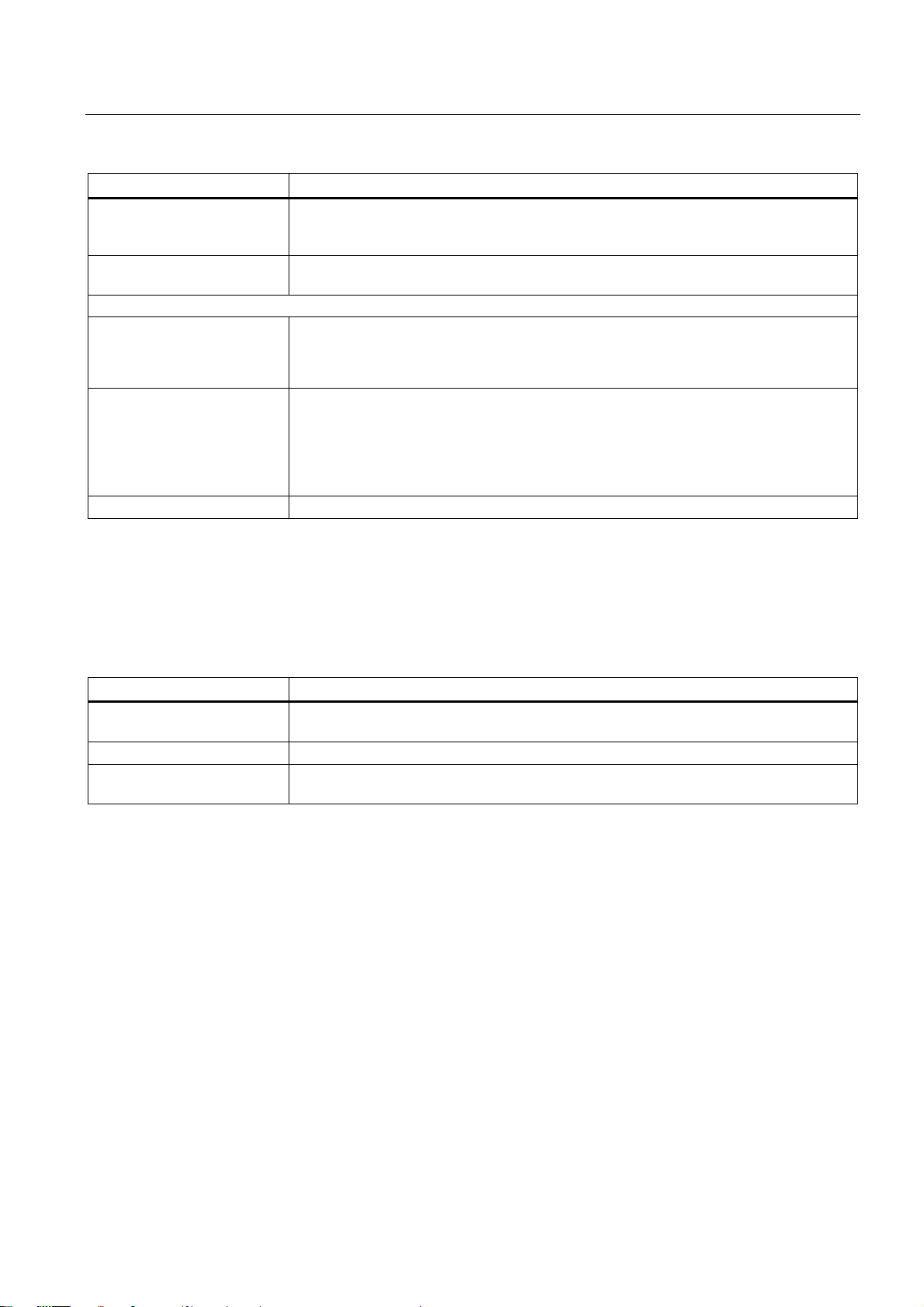
Component Function
SIMATIC ET 200pro Modular I/O system with IP65/IP67 rating for machine-related applications with no control
cabinet; with new features such as more compact designs, integrated PROFIsafe safety
technology, PROFINET connection and live module replacement.
SIMATIC ET 200eco I/O system with IP65/IP67 rating for machine-related applications with no control cabinet,
with a flexible and fast connection system in ECOFAST or M12.
Other PROFIBUS I/O
Gateways
Drive interfaces
Teleservice adapter Remote diagnostics
• DP/AS-Interface Link 20E and DP/AS-Interface Link Advanced for the PROFIBUS DP
gateway to AS-Interface
• DP/DP coupler to connect two PROFIBUS DP networks
• ADI4 (Analog Drive Interface for 4 axes) for the connection of drives with analog ±10 V
setpoint interface or for external encoders
• IM 174 (Interface Module for 4 axes) for the connection of drives with analog ±10 V
setpoint interface, external encoders or the connection of stepper drives with
pulse/direction interface
Ethernet
The control unit can communicate with the following components via the Ethernet interfaces
or be embedded in an automation environment:
Table 1- 3 Components on the Ethernet
Component Function
Programming device (PG/PC) ... configures, sets parameters, programs and tests using the SIMOTION SCOUT
Engineering System (ES).
Master computer ... communicates with other devices via UDP, TCP/IP.
SIMATIC HMI device ... is used for operator control and monitoring functions. This is not an essential
requirement for the operation of the SIMOTION D410-2.
SIMOTION D410-2
Manual, 02/2012
15
Page 16

Description
1.2 System components
DRIVE-CLiQ
SIMOTION D410-2 can communicate via the DRIVE-CLiQ interface with the following
components:
Table 1- 4 Components on DRIVE-CLiQ
Component Function
SINAMICS S120 AC DRIVE
drive units
(with CUA31/CUA32)
TM15, TM17 High Feature
terminal modules
TM31 terminal module ... enables terminal expansion via DRIVE-CLiQ (additional analog and digital I/Os).
TM41 terminal module ... enables terminal expansion (analog and digital I/Os) and encoder simulation via
TM54F terminal module ... enables terminal expansion (fail-safe digital I/Os) for controlling the safe motion
SMx sensor modules ... enable the acquisition of encoder data from the connected motors via DRIVE-CLiQ.
Motors with
DRIVE-CLiQ interface
DMC20/DME20
DRIVE-CLiQ hub
... convert speed setpoints into signals for controlling the motor and supply the power
required to operate the motors. The AC DRIVE component PM340 is connected via
CUA31/CUA32. No more than one PM340 can be connected. Power module chassis is
connected via DRIVE-CLiQ.
Note:
Components in booksize format are not supported!
The terminal modules TM15 and TM17 High Feature are used to implement inputs of
measuring inputs and outputs of cam outputs. In addition, these terminal modules provide
drive-related digital I/Os with short signal delay times.
DRIVE-CLiQ. The TM41 can be connected to a real axis.
monitoring functions of the integrated drive. A TM54F usually not necessary because the
SIMOTION D410-2 has three F-DI and one F-DO.
... allow simplified commissioning and diagnostics, as the motor and encoder type are
identified automatically.
... enables the number of DRIVE-CLiQ interfaces to be increased and the creation of a
point-to-point topology.
Note
Please note that components in booksize format (controller extension, motor modules, line
modules, etc.) as well as SINAMICS G120 (PM2x0) power modules are not supported by
SIMOTION D410-2.
Note
You can find detailed information about components in the SINAMICS S110/S120 family of
products in the SINAMICS S110/S120 manuals.
It is possible that older DRIVE-CLiQ components can no longer be used with
SIMOTION D410-2. You can find detailed information on this in SIMOTION D410-2
Commissioning and Hardware Installation Manual in Section "Migration of SIMOTION D410
to SIMOTION D410-2" at "Permissible combinations".
SIMOTION D410-2
16 Manual, 02/2012
Page 17

Description
1.3 I/O integration
1.3 I/O integration
Note
Note that not all modules in the ET 200 I/O family are approved for SIMOTION. Moreover,
system-related functional differences can come into play when these I/Os or I/O systems are
used on SIMOTION vs. on SIMATIC. For example, special process-control functions (e.g.
HART modules, etc.) are not supported by SIMOTION for the ET 200M distributed I/O
system.
A detailed, regularly updated list of the I/O modules approved for use with SIMOTION, as
well as notes on their use, can be found at Internet address
(http://support.automation.siemens.
com/WW/view/en/11886029)
In addition to the I/O modules released for SIMOTION, in principle all certified standard
PROFIBUS slaves (DP-V0/DP-V1/DP-V2) may be connected to SIMOTION D410-2. These
modules are integrated via the GSD file (PROFIBUS) of the device's manufacturer.
Note
Please note that in isolated cases, additional boundary conditions must be fulfilled in order to
integrate a module into SIMOTION. Thus, a few modules require "driver blocks" , e.g. in the
form of function blocks, that permit (or simplify) integration.
For modules enabled for SIMOTION (e.g. SIMATIC S7-300 module FM 350-1, etc.), these
driver modules are part of the SIMOTION SCOUT engineering system command library.
SIMOTION D410-2
Manual, 02/2012
17
 Loading...