

Page 1
Preface
1
SIMOTION
Motion control
Output Cams and Measuring Inputs
Function Manual
Fundamental safety
instructions
Output Cam TO - Part I
Cam Track TO - Part II
Measuring Input TO - Part III
2
3
4
5
Valid as of Version 4.4
04/2014
Page 2
Legal information
Warning notice system
This manual contains notices you have to observe in order to ensure your personal safety, as well as to prevent
damage to property. The notices referring to your personal safety are highlighted in the manual by a safety alert
symbol, notices referring only to property damage have no safety alert symbol. These notices shown below are
graded according to the degree of danger.
DANGER
indicates that death or severe personal injury will result if proper precautions are not taken.
WARNING
indicates that death or severe personal injury may result if proper precautions are not taken.
CAUTION
indicates that minor personal injury can result if proper precautions are not taken.
NOTICE
indicates that property damage can result if proper precautions are not taken.
If more than one degree of danger is present, the warning notice representing the highest degree of danger will be
used. A notice
warning of injury to persons with a safety alert symbol may also include a warning relating to property
damage.
Qualified Personnel
The product/system described in this documentation may be operated only by personnel qualified for the specific
task in accordance with the relevant documentation, in particular its warning notices and safety instructions. Qualified
personnel are those who, based on their training and experience, are capable of identifying risks and avoiding
potential hazards when working with these products/systems.
Proper use of Siemens products
Note the following:
WARNING
Siemens products may only be used for the applications described in the catalog and in the relevant technical
documentation.
If products
approved by Siemens. Proper transport, storage, installation, assembly, commissioning, operation and
maintenance are required to ensure that the products operate safely and without any problems. The permissible
ambient conditions must be complied with. The information in the relevant documentation must be observed.
and components from other manufacturers are used, these must be recommended or
Trademarks
All names identified by ® are registered trademarks of Siemens AG. The remaining trademarks in this publication
may be trademarks whose use by third parties for their own purposes could violate the rights of the owner.
Disclaimer of Liability
We have reviewed
Since variance cannot be precluded entirely, we cannot guarantee full consistency. However, the information in
this publication is reviewed regularly and any necessary corrections are included in subsequent editions.
Siemens AG
Industry Sector
Postfach 48 48
90026 NÜRNBERG
GERMANY
the contents of this publication to ensure consistency with the hardware and software described.
Copyright © Siemens AG 2014.
All rights reserved
Page 3

Table of contents
1 Preface.........................................................................................................................................................7
1.1 SIMOTION Documentation...........................................................................................................8
1.2 Hotline and Internet addresses.....................................................................................................9
2 Fundamental safety instructions.................................................................................................................11
2.1 General safety instructions..........................................................................................................11
2.2 Industrial security........................................................................................................................12
3 Output Cam TO - Part I..............................................................................................................................13
3.1 Overview of Output Cam TO.......................................................................................................13
3.1.1 General information about the Output Cam TO..........................................................................13
3.1.2 Functionality................................................................................................................................14
3.1.3 Comparison of Output Cam TO and Cam Track TO...................................................................16
3.2 Output cam TO basics.................................................................................................................18
3.2.1 Output cam type..........................................................................................................................18
3.2.1.1 Software cam..............................................................................................................................18
3.2.1.2 Hardware cam.............................................................................................................................18
3.2.1.3 Position-based cam.....................................................................................................................19
3.2.1.4 Time-based output cam...............................................................................................................20
3.2.1.5 Unidirectional output cam............................................................................................................21
3.2.1.6 Counter cam................................................................................................................................22
3.2.1.7 Cam output types........................................................................................................................22
3.2.1.8 Exact time setting of an output, exact time output cams (as of V4.1).........................................27
3.2.2 Cam parameters..........................................................................................................................29
3.2.2.1 Reaction, effective direction........................................................................................................29
3.2.2.2 Hysteresis....................................................................................................................................30
3.2.2.3 Derivative-action times (activation/deactivation time).................................................................32
3.2.2.4 Logical operation.........................................................................................................................34
3.2.2.5 Simulation....................................................................................................................................35
3.2.2.6 Inversion......................................................................................................................................35
3.2.3 Configure Units............................................................................................................................35
3.3 Configuring the Output Cam technology object...........................................................................37
3.3.1 Insertion of Output Cam..............................................................................................................37
3.3.2 Parameterize Output Cam technology object..............................................................................37
3.3.3 Using the expert list for output cams...........................................................................................38
3.3.4 Output cam configuration............................................................................................................38
3.3.5 Defining output cam defaults.......................................................................................................43
3.3.6 Determining derivative-action times for output cams (dead time compensation)........................45
3.3.7 Configuring cams on SIMOTION D4xx onboard.........................................................................47
3.3.8 Configuring output cams on SIMOTION D410-2.........................................................................50
3.3.9 Configuring cams on SIMOTION D4x5-2 onboard......................................................................52
3.3.10 Configuring an output cam on a TM15/TM17 High Feature........................................................53
3.3.11 Configuring cams on SIMOTION C240.......................................................................................55
3.3.12 HW enable for Output Cam TO...................................................................................................55
Output Cams and Measuring Inputs
Function Manual, 04/2014 3
Page 4

Table of contents
3.4 Programming/references of Output Cam TO..............................................................................56
3.4.1 Programming...............................................................................................................................56
3.4.2 Commands..................................................................................................................................57
3.4.3 Process Alarms...........................................................................................................................58
3.4.4 Output Cam TO menus...............................................................................................................59
3.4.4.1 Output cam menu........................................................................................................................59
3.4.4.2 Output cam context menu...........................................................................................................59
4 Cam Track TO - Part II...............................................................................................................................61
4.1 Overview of TO Cam Track.........................................................................................................61
4.1.1 General information about Cam Track TO..................................................................................61
4.1.2 Functionality................................................................................................................................62
4.1.3 Comparison of Output Cam TO and Cam Track TO...................................................................64
4.2 TO Cam Track basics..................................................................................................................66
4.2.1 Cam track features......................................................................................................................66
4.2.2 Output cam types of the single output cams on a track..............................................................67
4.2.2.1 Software cam..............................................................................................................................67
4.2.2.2 Hardware cam.............................................................................................................................67
4.2.2.3 Position-based cam.....................................................................................................................68
4.2.2.4 Time-based output cam...............................................................................................................69
4.2.2.5 Time-based cam with maximum ON length................................................................................70
4.2.2.6 Cam output types........................................................................................................................71
4.2.3 Cam track parameters.................................................................................................................76
4.2.3.1 Track length.................................................................................................................................76
4.2.3.2 Effective direction and behavior..................................................................................................76
4.2.3.3 Hysteresis....................................................................................................................................77
4.2.3.4 Derivative-action times (activation time/deactivation time)..........................................................79
4.2.3.5 Cam track activation....................................................................................................................81
4.2.3.6 Cam track deactivation................................................................................................................81
4.2.3.7 Leave cam track active in the axis range (as of V4.1).................................................................82
4.2.3.8 Start mode and stop mode..........................................................................................................83
4.2.3.9 Output activation mode...............................................................................................................85
4.2.3.10 Axis reference position and cam track offset...............................................................................85
4.2.3.11 Simulation....................................................................................................................................86
4.2.4 Configure Units............................................................................................................................86
4.2.5 Mapping a cam track onto an axis...............................................................................................87
4.2.5.1 Basics of cam track mapping......................................................................................................88
4.2.5.2 Mapping output cams onto the cam track...................................................................................88
4.2.5.3 Mapping onto negative axis positions (e.g. linear axes)..............................................................89
4.2.5.4 Relation of track length, modulo length and activation mode in mapping...................................90
4.2.6 Cam track operating behavior.....................................................................................................93
4.2.6.1 Changing output cams on a cam track during runtime................................................................93
4.2.6.2 Changing the track length during operation................................................................................94
4.2.6.3 Changing the axis configuration when a cam track is active.......................................................95
4.2.6.4 Calling up the status of cam tracks and single output cams.......................................................95
4.2.7 Inverting a cam track...................................................................................................................95
4.2.8 Effect of cam track parameters on mapping................................................................................96
4.2.8.1 Basic mapping of a simple cam track..........................................................................................96
4.2.8.2 Advanced mappings with shifted output cam positions...............................................................97
4.3 Configuring the TO Cam Track...................................................................................................99
4.3.1 Inserting cam tracks....................................................................................................................99
Output Cams and Measuring Inputs
4 Function Manual, 04/2014
Page 5

Table of contents
4.3.2 Parameterizing the Cam Track technology object.....................................................................100
4.3.3 Using expert list for cam tracks.................................................................................................100
4.3.4 Configuring a cam track............................................................................................................101
4.3.5 Defining cam track defaults.......................................................................................................105
4.3.5.1 Track data.................................................................................................................................105
4.3.5.2 Output cam data........................................................................................................................108
4.3.6 Configuring cam tracks on SIMOTION D4xx onboard..............................................................109
4.3.7 Configuring cam track on the SIMOTION D410-2.....................................................................111
4.3.8 Configuring cam tracks on SIMOTION D4x5-2 onboard...........................................................113
4.3.9 Configuring cam tracks on a TM15/TM17 High Feature...........................................................114
4.3.10 Configuring cam tracks on SIMOTION C240............................................................................116
4.3.11 Determining derivative-action times for cam tracks (dead time compensation)........................116
4.3.12 Using HW enable for cam tracks...............................................................................................118
4.3.12.1 Absolute level-controlled (TM17 High Feature).........................................................................119
4.3.12.2 Absolute edge-controlled (TM17 High Feature)........................................................................120
4.3.12.3 Setting (overriding) the enable via a program...........................................................................121
4.3.12.4 Relative edge-controlled............................................................................................................122
4.4 Programming/References of TO Cam Track.............................................................................123
4.4.1 Programming.............................................................................................................................123
4.4.2 Commands................................................................................................................................124
4.4.3 Process Alarms.........................................................................................................................125
4.4.4 TO Cam Track menus...............................................................................................................126
4.4.4.1 Cam track menu........................................................................................................................126
4.4.4.2 Cam track context menu...........................................................................................................126
5 Measuring Input TO - Part III....................................................................................................................129
5.1 Overview of Measuring Input TO...............................................................................................129
5.1.1 General information about the Measuring Input TO..................................................................129
5.2 Fundamentals of Measuring Input technology object................................................................131
5.2.1 Measuring input types - local and global measuring inputs.......................................................131
5.2.2 Hardware for measuring inputs.................................................................................................132
5.2.3 Interconnections........................................................................................................................133
5.2.3.1 Measuring input connection options..........................................................................................134
5.2.3.2 Several Measuring Input TOs on one axis/encoder (as of V3.2)...............................................135
5.2.3.3 More than one measuring input TO on a single measuring input (C230-2/C240 only).............136
5.2.3.4 Measuring one measurement event on several axes - Listening measuring input (V4.0 and
later)..........................................................................................................................................136
5.2.4 Measurement............................................................................................................................139
5.2.4.1 One-time measurement.............................................................................................................139
5.2.4.2 Cyclic measurement (as of V3.2)..............................................................................................141
5.2.4.3 Lost edges during cyclic measurement.....................................................................................144
5.2.4.4 Measurement activation times...................................................................................................147
5.2.5 Measuring range.......................................................................................................................148
5.2.6 Configure Units..........................................................................................................................151
5.2.7 Simulation..................................................................................................................................152
5.3 Configuring the Measuring Input technology object..................................................................153
5.3.1 Inserting Measuring Inputs........................................................................................................153
5.3.2 Parameterization of the Measuring Input technology object.....................................................153
5.3.3 Use Expert List for Measuring Inputs........................................................................................154
5.3.4 Measuring Input Configuration..................................................................................................154
5.3.4.1 Measuring Input Configuration..................................................................................................154
Output Cams and Measuring Inputs
Function Manual, 04/2014 5
Page 6

Table of contents
5.3.4.2 Time stamp correction value.....................................................................................................159
5.3.5 Measuring input defaults...........................................................................................................160
5.3.6 Local measuring........................................................................................................................163
5.3.6.1 Local measuring on C230-2, C240 (not C240 PN)....................................................................163
5.3.6.2 Local measurement on D4xx, D410-2, D4x5-2 (X122/X132), CX32, CX32-2, CU310,
CU310-2, CU320 and CU320-2................................................................................................163
5.3.6.3 Local measuring on other drives (MASTERDRIVES MC, SIMODRIVE 611U, etc.).................163
5.3.7 Global measuring......................................................................................................................164
5.3.7.1 Global measuring on TM15/TM17 High Feature.......................................................................164
5.3.7.2 Global measuring on C240/C240 PN (B1-B4)...........................................................................167
5.3.7.3 Global measurement on D4xx, D410-2, D4x5-2 (X122/X132), CX32, CX32-2, CU310,
CU310-2, CU320 and CU320-2................................................................................................167
5.3.7.4 Global measuring on D4x5-2 (X142).........................................................................................170
5.3.8 Configuring and interconnecting a listening Measuring Input TO.............................................174
5.3.9 Measuring input with hardware enable (TM17 High Feature)...................................................175
5.4 Measuring Input technology object programming/references...................................................177
5.4.1 Programming.............................................................................................................................177
5.4.2 Commands................................................................................................................................178
5.4.3 Process Alarms.........................................................................................................................179
5.4.4 Measuring input menus.............................................................................................................179
5.4.4.1 Measuring Input technology object menu..................................................................................179
5.4.4.2 Measuring input TO context menu............................................................................................180
Index.........................................................................................................................................................183
Output Cams and Measuring Inputs
6 Function Manual, 04/2014
Page 7

Preface
1
This document is part of the
System and Function Descriptions documentation package.
Scope
This manual applies to SIMOTION SCOUT in connection with the SIMOTION Cam, Path or
Cam_ext technology package for product version V4.4.
Chapters in this manual
This manual provides information about the functions, operation, command execution, and
technology alarms of the technology objects.
● Output Cam technology object (part I)
Functions and operation
● Cam Track technology object (part II)
Functions and operation
● TO measuring input (part III)
Functions and operation
● Index
Keyword index for locating information
Output Cams and Measuring Inputs
Function Manual, 04/2014 7
Page 8

Preface
1.1 SIMOTION Documentation
1.1 SIMOTION Documentation
An overview of the SIMOTION documentation can be found in the SIMOTION Documentation
Overview document.
This documentation is included as electronic documentation in the scope of delivery of
SIMOTION SCOUT. It comprises ten documentation packages.
The following documentation packages are available for SIMOTION V4.4:
● SIMOTION Engineering System Handling
● SIMOTION System and Function Descriptions
● SIMOTION Service and Diagnostics
● SIMOTION IT
● SIMOTION Programming
● SIMOTION Programming - References
● SIMOTION C
● SIMOTION P
● SIMOTION D
● SIMOTION Supplementary Documentation
Output Cams and Measuring Inputs
8 Function Manual, 04/2014
Page 9

1.2 Hotline and Internet addresses
Additional information
Click the following link to find information on the the following topics:
● Ordering documentation / overview of documentation
● Additional links to download documents
● Using documentation online (find and search manuals/information)
http://www.siemens.com/motioncontrol/docu
Please send any questions about the technical documentation (e.g. suggestions for
improvement, corrections) to the following e-mail address:
[email protected]
My Documentation Manager
Click the following link for information on how to compile documentation individually on the
basis of Siemens content and how to adapt it for the purpose of your own machine
documentation:
Preface
1.2 Hotline and Internet addresses
Training
FAQs
Technical support
http://www.siemens.com/mdm
Click the following link for information on SITRAIN - Siemens training courses for automation
products, systems and solutions:
http://www.siemens.com/sitrain
Frequently Asked Questions can be found in SIMOTION Utilities & Applications, which are
included in the scope of delivery of SIMOTION SCOUT, and in the Service&Support pages
in Product Support:
http://support.automation.siemens.com
Country-specific telephone numbers for technical support are provided on the Internet under
Contact:
http://www.siemens.com/automation/service&support
Output Cams and Measuring Inputs
Function Manual, 04/2014 9
Page 10

Page 11
Fundamental safety instructions
2.1 General safety instructions
2
WARNING
Risk of death if the safety instructions and remaining risks are not carefully observed
If the safety instructions and residual risks are not observed in the associated hardware
documentation, accidents involving severe injuries or death can occur.
● Observe the safety instructions given in the hardware documentation.
●
Consider the residual risks for the risk evaluation.
WARNING
Danger to life or malfunctions of the machine as a result of incorrect or changed
parameterization
As a result of incorrect or changed parameterization, machines can malfunction, which in
turn can lead to injuries or death.
● Protect the parameterization (parameter assignments) against unauthorized access.
Respond to possible malfunctions by applying suitable measures (e.g. EMERGENCY
●
STOP or EMERGENCY OFF).
Output Cams and Measuring Inputs
Function Manual, 04/2014 11
Page 12
Fundamental safety instructions
2.2 Industrial security
2.2 Industrial security
Note
Industrial security
Siemens provides products and solutions with industrial security functions that support the
secure operation of plants, solutions, machines, equipment and/or networks. They are
important components in a holistic industrial security concept. With this in mind, Siemens’
products and solutions undergo continuous development. Siemens recommends strongly
that you regularly check for product updates.
the
For
secure operation of Siemens products and solutions, it is necessary to take suitable
preventive action (e.g. cell protection concept) and integrate each component into a holistic,
state-of-the-art industrial security concept. Third-party products that may be in use should
also be considered. For more information about industrial security, visit http://
www.siemens.com/industrialsecurity.
To stay informed about product updates as they occur, sign up for a product-specific
newsletter. For more information, visit http://support.automation.siemens.com
WARNING
Danger as a result of unsafe operating states resulting from software manipulation
Software manipulation (e.g. by viruses, Trojan horses, malware, worms) can cause unsafe
operating states to develop in your installation which can lead to death, severe injuries and/
or material damage.
●
Keep the software up to date.
Information and newsletters can be found at:
http://support.automation.siemens.com
Incorporate the automation and drive components into a state-of-the-art, integrated
●
industrial security concept for the installation or machine.
For more detailed information, go to:
http://www.siemens.com/industrialsecurity
● Make sure that you include all installed products into the integrated industrial security
concept.
Output Cams and Measuring Inputs
12 Function Manual, 04/2014
Page 13
Output Cam TO - Part I
([WHUQDOHQFRGH
U
$[LV
2XWSXW&DP72
2XWSXW&DP72
2XWSXW
2XWSXW
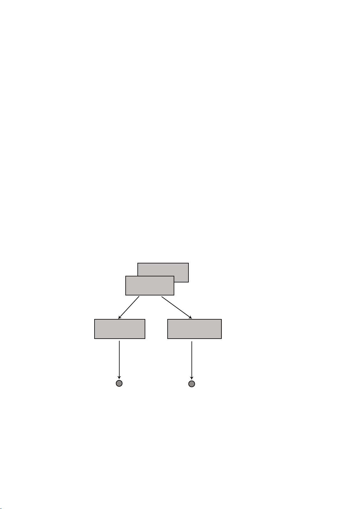
3.1 Overview of Output Cam TO
3.1.1 General information about the Output Cam TO
Output Cam technology object
The
● Generates position-dependent switching signals
● Can be assigned to positioning axes, synchronous axes, path axes or external encoders
● The axes can be real or virtual.
Different switching signals distinguish different types of output cam:
● Software cam
Switching signals are used internally in the user program by evaluating the relevant state
system variable.
● Hardware cam
Switching signals are output externally on I/O devices by assigning a digital output to the
Output Cam TO. For example, digital output modules from the ET 200 I/O system can be
used for the cam output.
3
Output Cams and Measuring Inputs
Function Manual, 04/2014 13
Figure 3-1 Interconnection options for the output cam TO
Page 14
Output Cam TO - Part I
3.1 Overview of Output Cam TO
A range of output cam types with different switching behaviors are available.
● Position-based cam
The switching
● Time-based cam
The switching signal is supplied for a specified time period after the switch-on position is
reached.
● Unidirectional output cam
The switching signal is supplied when the axis reaches the switching position and is then
reset by the user.
● Counter cam
Counter cams are not a separate output cam type, but rather position-based or time-based
type cams. Counter cams can be configured so that they are output for every switching or
for every nth switching. They can only be programmed and activated in the user program.
● Cam output types
While output cams are usually output in the IPO cycle clock or the position control cycle
clock, high-speed output cams provide better output accuracy than the position control
cycle clock because the switching edges are positioned within the position control cycle
clock.
signal is supplied between the switch-on position and the switch-off position.
3.1.2 Functionality
It is possible to define an effective direction for the Output Cam TO, i.e. the output cam is only
active when the direction of motion of the axis is the same as the effective direction.
The output cam can be calculated in servo cycles, IPO cycles, or IPO_2 cycles.
Note
With modules D435-2 DP/PN, D445-2 DP/PN, and D455-2 DP/PN, cam calculation can be
performed in Servo_fast or IPO_fast. For more information, see the chapter Second servo
cycle clock (Servo_fast) in the Motion Control Basic Functions manual.
The reference values of the output cam depend on the axis type or the external encoder:
Table 3-1 Reference to the actual or set position
Technology object Reference to actual position
Real drive axis - Real position axis X X
Real synchronized axis X X
Virtual axes - X
External encoder X -
possible
Reference
to set position possible
Possible configuration of the cams with actual value reference:
Output Cams and Measuring Inputs
14 Function Manual, 04/2014
Page 15

Output Cam TO - Part I
3.1 Overview of Output Cam TO
● Reference to
the actual value on the encoder without considering Ti. Reference to the actual
position in the controller before the position filter.
● Reference to the actual value after the position filter. Reference to the actual position in the
controller after the position filter.
● Reference to the actual value on the encoder. Ti is taken into account. Reference to the
actual value on the encoder module / drive. The transmission time Ti from the encoder
module / drive to the controller is taken into account by the system.
Possible configuration of the cams with setpoint reference:
● Reference to the setpoint after the fine interpolator. The cam switch points are calculated
as if the setpoints will already have been reached at the end of this IPO cycle, e.g. if a
setpoint is calculated for the IPO cycle clock with the virtual axis and also displayed at the
end of the cycle. Reference is made directly to the setpoint applicable at the end of the
cycle.
● Reference to the setpoint after the fine interpolator. The cam switch points are calculated
as if the setpoint calculated in the interpolator will be output completely in the following
cycle and the calculated position setpoint will therefore be reached at the end of the
following cycle.
● Reference to the setpoint on the drive. Calculation of the cam switch points according to
the setpoint output with the current settings on the drive.
In this case, the output cam functionality can be applied to axes or external encoders with or
without modulo properties.
The output cam is also effective for axes that have not been homed.
The Output Cam technology object is assigned to exactly one output during configuration.
Output can be achieved via:
● Onboard I/O
● Drive I/O (e.g. TB30, TM31, TM1x)
● SIMOTION C centralized I/O
● Distributed I/O; PROFIBUS DP I/O (e.g. ET 200M)
However, the output must not be in the process image.
The switching accuracy is dependent on the following:
● Output accuracy of the I/O
● How the output cam is allocated in the task system
● How constant delay times are compensated
Several Output Cam TOs can be connected to the same output (see Chapter Logical
operation). Alternatively, the Cam Track TO can be used for this purpose.
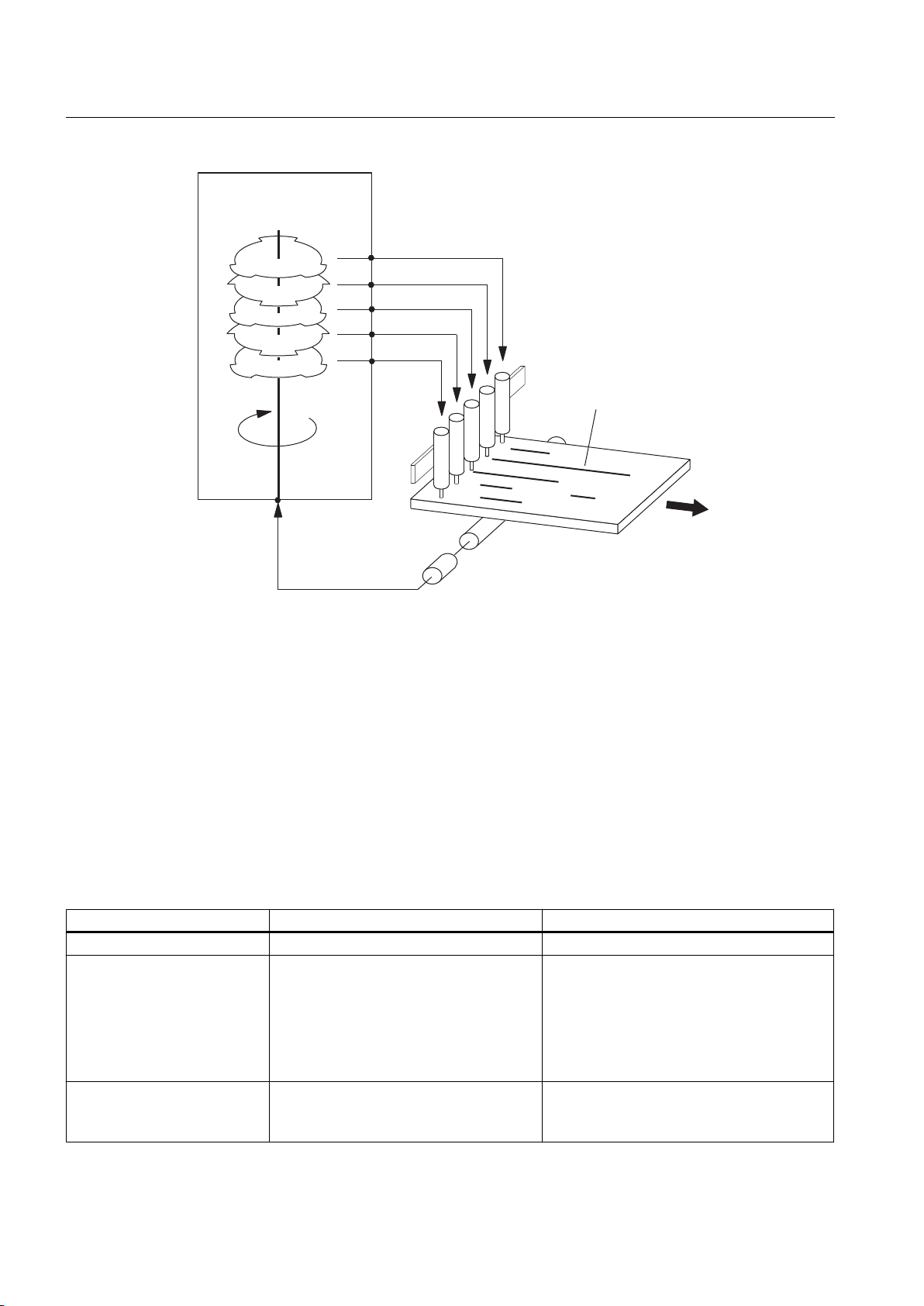
Example
Lines of glue are applied to a wooden board. The output cams are assigned to an external
encoder. Output cams assigned to outputs Q 0 to Q 4 are switched on and off at specified
positions.
Output Cams and Measuring Inputs
Function Manual, 04/2014 15
Page 16
'LJLWDORXWSXWVWULJJHUUHVSRQVHV
2XWSXWFDP
IXQFWLRQDOLW\
/LQHVRIJOXH
&RQYH\RUGLUHFWLRQ
(QFRGHUVHQVHVSRVLWLRQRID[LV
Output Cam TO - Part I
3.1 Overview of Output Cam TO
Figure 3-2 Example of an electronic cam control
See also
Logical operation (Page 34)
3.1.3 Comparison of Output Cam TO and Cam Track TO
Depending on the application, it may be practical to use either the Cam Track TO or one or
more Output Cam TOs. The table below should help you to decide which TO should be used
in which case.
Table 3-2 Comparison of Output Cam TO and Cam Track TO
Features Output Cam TO Cam Track TO
Availability ● As of Version 1.0 ● As of Version V3.2
Supported output cams ● Position-based cam
Several output cams on one
output
● Time-based output cam
Unidirectional output cam
●
● Counter cam
● Exact time setting of an output, exact
time output cams (as of V4.1)
● Via logical operation (AND/OR) ● Maximum 32 output cams of the same
● Position-based cam
● Time-based output cam
● Time-based cam with maximum ON length
type in one track
● No cam
track logical operations (AND/OR)
Output Cams and Measuring Inputs
16 Function Manual, 04/2014
Page 17

Output Cam TO - Part I
3.1 Overview of Output Cam TO
Features Output Cam TO Cam Track TO
Different types of output cam
on one output
Output cam definition ● Related to axis
Hysteresis ● Available ● Available
Effective direction ● Available ● Not available
Derivative-action times ● Separate for power ON/power OFF ● Separate for power ON/power OFF
Deactivation time for time-
based cam
Activation/deactivation types ● Active immediately ● Start and stop mode parameterizable
Types of output ● Cyclic ● Cyclic
Output cam status ●
Output cam enable ● Via_enableOutputCam ● via_enableCamTrack
Performance ● Depends on number of single output
MCC command available ● Available ● Available (V4.0 and higher)
● Via AND/OR ● Not available
● Related to cam track (cam track can be
Via system variables
●
● As of Version V3.2 ● As of Version V3.2
System variable ● Status of single output cams over one
cams
mapped as required on axis)
● Via system-variables array
Once
●
array of byte
of
● Validity
via system variables
● When 5 or more output cams are used in
one output cam track instead of 5 single
output cams, the output cam track
performs better. This performance
advantage amounts to at least a factor of
2 for 32 single output cams.
single output cams configurable
Output Cams and Measuring Inputs
Function Manual, 04/2014 17
Page 18

Output Cam TO - Part I
3.2 Output cam TO basics
3.2 Output cam TO basics
3.2.1 Output cam type
3.2.1.1 Software cam
Switching signals are used internally in the user program by evaluating the relevant state
system variable.
3.2.1.2 Hardware cam
Description
Switching signals are output externally on I/O devices by assigning a digital output to the Output
Cam TO.
The following can be used as digital outputs:
● Onboard outputs (SIMOTION C, D, ...)
● Centralized I/O (SIMOTION C)
● Distributed I/Os via PROFIBUS DP (e.g. ET 200M) and PROFINET IO (e.g. ET 200S)
● Drive I/O (for example, TM15 and TM17 High Feature terminal modules)
Hardware for output cams
Cam output on cam output (I/O channel is configured as CAM)
● SIMOTION D410-2
● SIMOTION D4x5-2
● TM15, TM17 High Feature
Cam output on high-speed output with direct access (I/O channel is configured as DO)
● SIMOTION D4xx / D4x5-1
● SIMOTION C240, C240 PN
Cam output on standard output (I/O channel is configured as DO)
● SIMOTION C/D/CX onboard I/O
● SINAMICS onboard I/O
● TM15, TM15 DI/DO, TM17 High Feature, TM31, TM41, TB30
● Standard DO (SIMATIC ET200, ...)
Output Cams and Measuring Inputs
18 Function Manual, 04/2014
Page 19
For more information, see cam output types. (Page 22)
&DPDFWLYDWLRQUDQJH
6WDUWLQJSRVLWLRQ(QGSRVLWLRQ
&DPDFWLYDWLRQUDQJH
6WDUWLQJSRVLWLRQ
(QGSRVLWLRQ
&DPDFWLYDWLRQUDQJH
3.2.1.3 Position-based cam
Output Cam TO - Part I
3.2 Output cam TO basics
Direction-neutral switching
Figure 3-3 Position-controlled output cam with start position less than end position
Limits imposed by start and end positions
The output cam is activated:
● Axis position is within the switch-on area
●
Axis position value is shifted into the switch-on area of the output cam
The position value of the interconnected object can change abruptly, for example, when it
is homed or when its coordinate system is shifted with the _redefinePosition command.
The output cam is switched off:
● When the axis position is outside the start or end position
● When the axis position value is shifted outside the switch-on area
● When commands are issued that deactivate the output cam, e.g. _disableOutputCam,
_setOutputCamState, and _resetOutputCam
Output Cams and Measuring Inputs
Function Manual, 04/2014 19
Switch-on area
The switch-on area of the output cam is defined from the start position to the end position in
a positive counting direction, i.e. within a range between the start position and the end position.
If the end position is greater than the start position, the switch-on area is defined by the start
and end positions (see figure above).
The switch-on area is outside the area between the end and start positions if the end position
is less than the start position (see figure below).
Figure 3-4 Position-controlled output cam with end position less than start position
Page 20
21GXUDWLRQ
6WDUWLQJSRVLWLRQ
Output Cam TO - Part I
3.2 Output cam TO basics
Note
This definition of the switch-on area is possible for all modulo and non-modulo axes.
ON duration
The ON duration of the output cam depends on the velocity at which the axis traverses the
output cam length.
Direction-dependent switching
The output cam is activated:
● When the axis position is between the start and end positions, and the axis is moving in
the programmed effective direction
The output cam is switched off:
When the axis position is outside the start or end position
●
● When the motion direction is not the same as the assigned effective direction
● When the axis position value is shifted outside the switch-on area
● When commands are issued that deactivate the output cam, e.g. _disableOutputCam,
_setOutputCamState, and _resetOutputCam
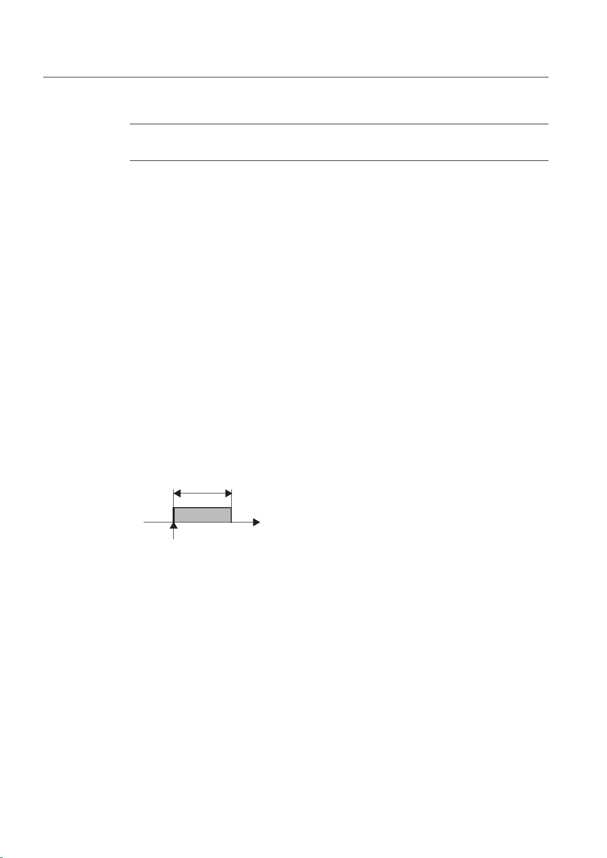
3.2.1.4 Time-based output cam
Direction-neutral switching
Figure 3-5 Time-controlled output cam
Limits imposed by starting position and ON duration
The output cam is switched on:
● At the starting position.
If the starting position is overrun again during the ON duration, the time-based cam is not
switched on again. It is not possible to retrigger a time-based cam.
20 Function Manual, 04/2014
The output cam is switched off:
●
When the assigned time period expires
● When commands are issued that deactivate the output cam, e.g. _disableOutputCam,
_setOutputCamState and _resetOutputCam
Output Cams and Measuring Inputs
Page 21
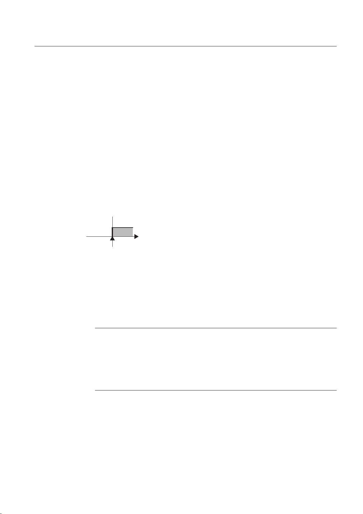
Output cam length
6WDUWLQJSRVLWLRQ
The output
cam length is dependent on the velocity at which the assigned axis traverses during
ON duration of the output cam.
Direction-dependent switching
The output cam is switched on:
● At the starting position if the traversing direction is the same as the effective direction
The output cam is switched off:
● When the assigned time period expires
● When commands are issued that deactivate the output cam, e.g. _disableOutputCam,
_setOutputCamState and _resetOutputCam
A change of direction will not lead to the output cam being switched off if the time-based cam
has already been activated.
3.2.1.5 Unidirectional output cam
Output Cam TO - Part I
3.2 Output cam TO basics
Figure 3-6 Unidirectional output cam
Limits imposed by starting position
The output cam is switched on:
● At the starting position if the axis is moving in the programmed effective direction
The output cam is switched off:
● By the _disableOutputCam, _setOutputCamState and _reset commands
Note
The unidirectional output cam does not switch unless the starting position is explicitly
crossed, e.g. by setting the actual value.
An end position is not defined for the unidirectional output cam. The output cam signal
depends solely on the switching criteria when the output cam is crossed over. The
unidirectional cam can be reset via the program (e.g. by calling up the system function
_enableOutputCam again).
Output Cams and Measuring Inputs
Function Manual, 04/2014 21
Page 22
3 24 3401
2XWSXWFDPFDP7\SH
&XUUHQWFRXQW
YDOXH
2XWSXW
3URJUDPPHGVWDUWLQJYDOXH
Output Cam TO - Part I
3.2 Output cam TO basics
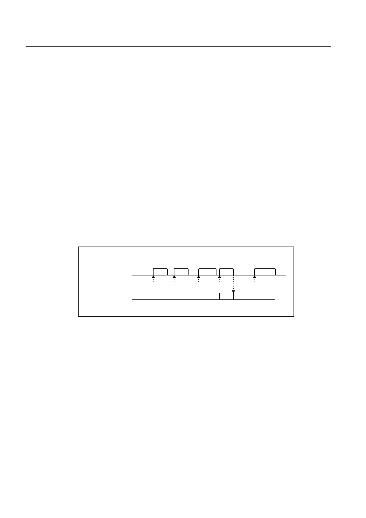
3.2.1.6 Counter cam
For a counter cam, it can be specified whether the output cam is to be output every time it
switches or every nth time it switches.
Note
Counter cams can only be configured for position-based and time-based cams. A counter
cam is used via the _setOutputCamCounter system function.
Counter cams can only be defined in the user program. In configuring the output cam, the
output cam type cannot be defined as counter cam.
Every counter cam has a starting count value and a current count value.
The current
If the current count reaches 0, the output cam is output (state system variable and output cam
output). At the same time, the current count value is reset to the starting count value. If the
current count value does not reach 0, the output cam output is suppressed. The default setting
of the starting count value and current count value is 1. The starting count value and current
count value are programmed by means of the _setOutputCamCounter. The current count
values can be scanned with the counterCamData.actualValue and
counterCamData.startValue system variables. No resetting of the values by the system takes
place, e.g. after _enableOutputCam or _disableOutputCam.
Figure 3-7 Example of a counter cam
3.2.1.7 Cam output types
count value for the output cam is reduced by 1 every time the output cam switches.
22 Function Manual, 04/2014
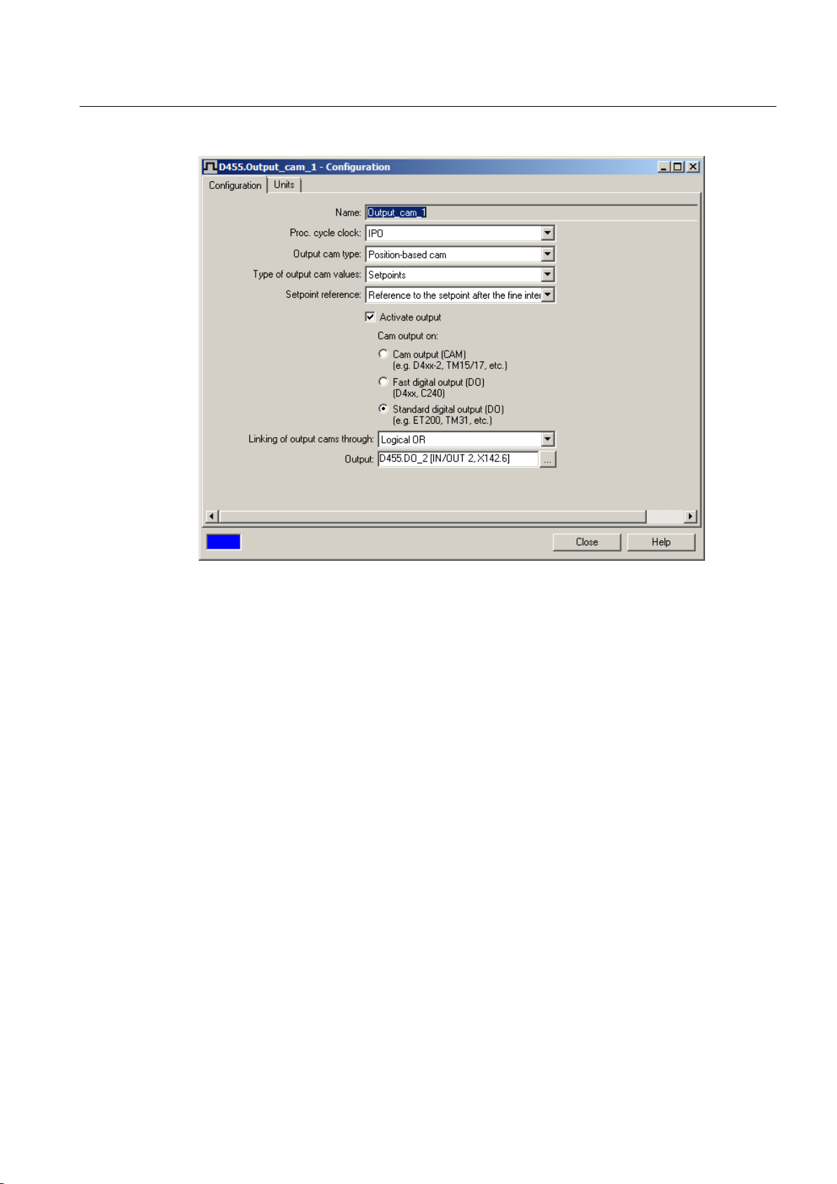
The cam calculations are performed in the processing cycle clock (IPO or IPO_2 cycle clock
or in the servo cycle clock). For the possible setting of Servo_fast or IPO_fast, see Chapter
Second servo cycle clock (Servo_fast) in the SIMOTION Runtime Basic Functions manual.
The temporal resolution of the cam output depends on the hardware used and the setting in
configuration. In standard applications, the setting is undertaken using screen forms. The
the
configuration data can also be set via the expert list.
The possible setting options for cam output are described below:
Output Cams and Measuring Inputs
Page 23
Output Cam TO - Part I
3.2 Output cam TO basics
Figure 3-8 Output cam configuration using the example of a position-based cam
Output Cams and Measuring Inputs
Function Manual, 04/2014 23
Page 24
Output Cam TO - Part I
3.2 Output cam TO basics
Cam output (CAM)
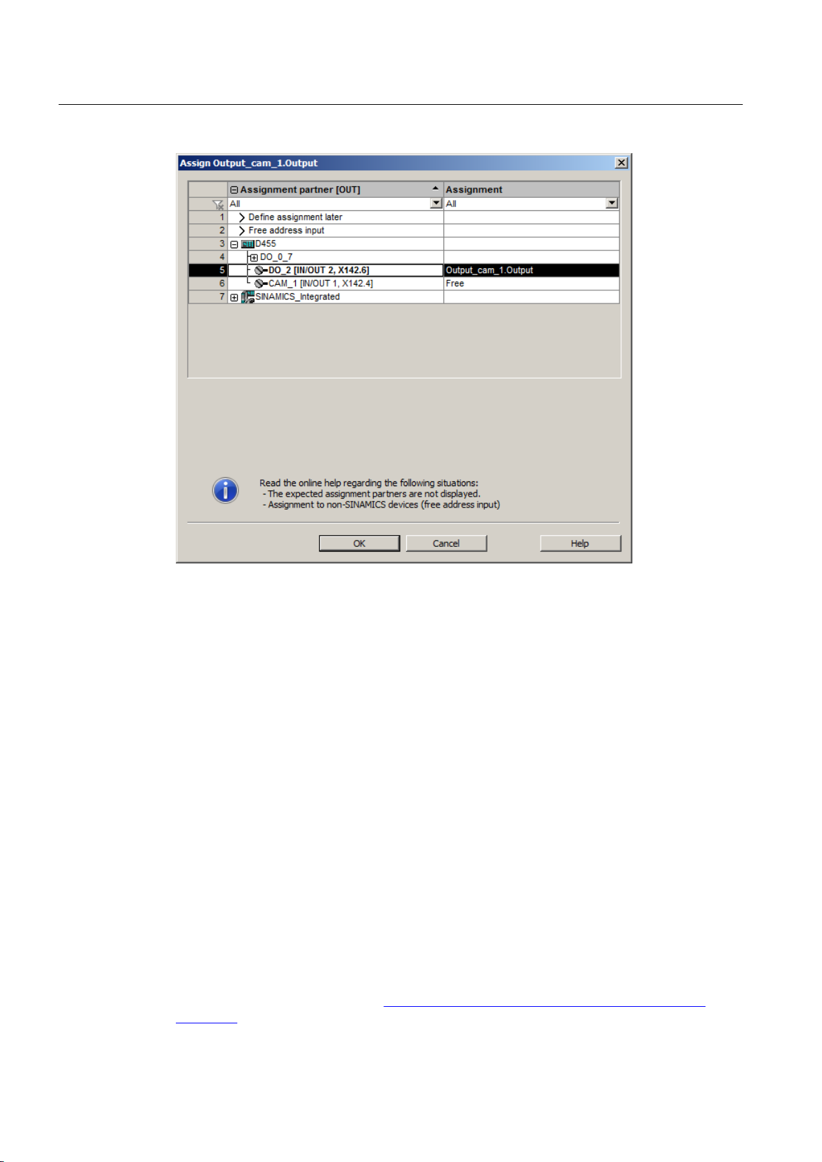
Figure 3-9 Assignment dialog
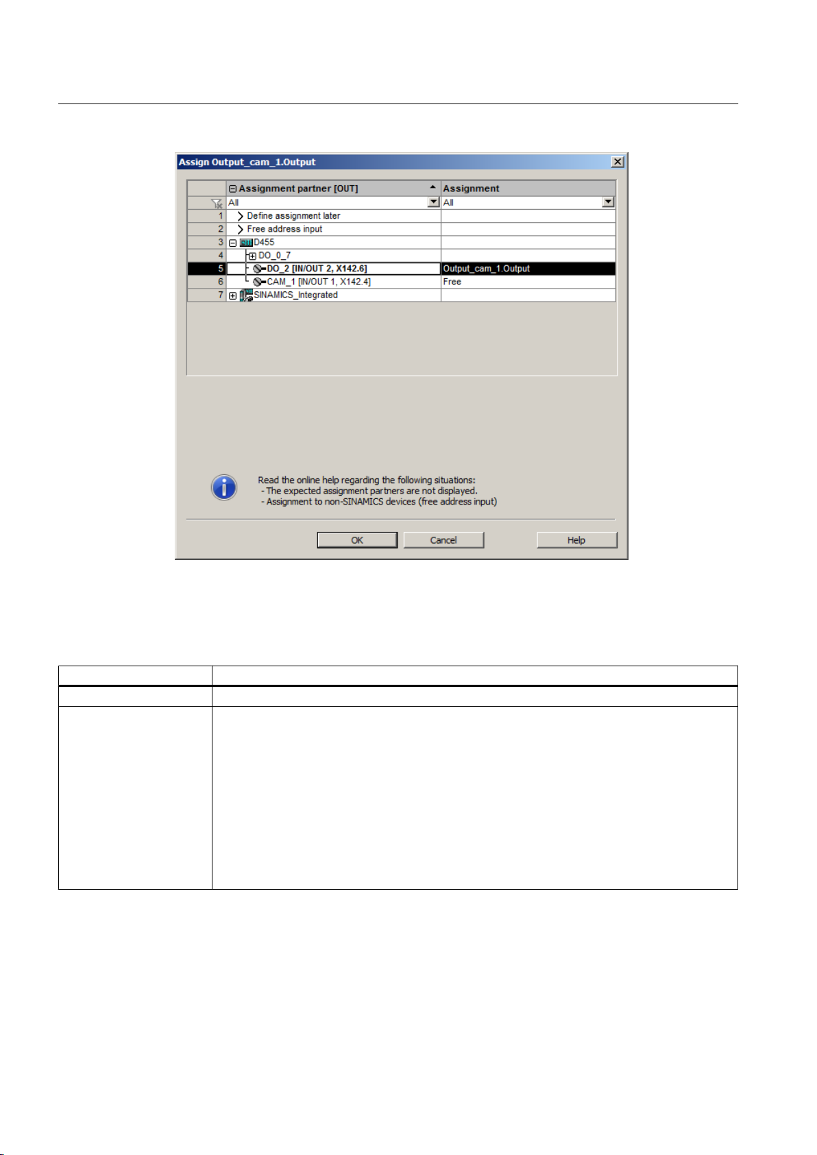
Symbolic assignment is activated by default in projects as of V4.2 (Project > Use symbolic
assignment)
The cam output is performed on the basis of an internal time stamp. The temporal resolution
of the cam output depends on the hardware used. In the case of D4x5-2 and the TM17 High
Feature, the resolution is 1 µs.
Hardware supported
● SIMOTION D410-2
● SIMOTION D4x5-2 (X142)
● TM15, TM17 High Feature
The I/O channel must be configured as CAM.
SIMOTION D410-2
The digital inputs/outputs are used for the cam output in the D410-2. The digital inputs/outputs
can be used as the cam output (CAM) from the user program.
As of the editorial deadline of this documentation, the output cam resolution for D410-2 was
not yet certain. The information can be found at the following website Additional information
about the SIMOTION D manuals (http://support.automation.siemens.com/WW/view/en/
27585482).
Output Cams and Measuring Inputs
24 Function Manual, 04/2014
Page 25

Output Cam TO - Part I
3.2 Output cam TO basics
SIMOTION D4x5-2 onboard outputs (interface X142)
The D4x5-2 onboard outputs can be used as cam output (CAM) from the user program. The
D4x5-2 onboard outputs are permanently assigned to SIMOTION. The X142 I/Os are
configured using HW Config.
The X142 configuration screen form can be accessed directly from the project navigator in
SIMOTION SCOUT.
With SIMOTION D4x5-2, output cams are output at the X142 interface with a resolution of 1
μs.
TM15 / TM17 High Feature Terminal Modules
The TM15
and TM17 High Feature Terminal Modules can be used to set up cam outputs (CAM)
within the SIMOTION Motion Control system. The Terminal Modules are connected directly to
SIMOTION D or CX32/CX32-2 via DRIVE-CLiQ for this purpose.
Alternatively, TM15 and TM17 High Feature can be connected to a SINAMICS S120 CU320/
CU320-2/CU310/CU310-2 Control Unit with higher-level SIMOTION C, P or D.
Output cams on the TM15 operate with DRIVE-CLiQ cycle-clock resolution (typically 125 µs).
Output cams on the TM17 High Feature have a resolution of 1 µs.
If current controller cycle clocks other than 125 μs are used, the parameter calculations of the
drive must be taken over into the PG and the Fast IO configuration must be recreated when
using cam outputs on TM15/TM17 High Feature. (For more information, see chapter Current
controller cycle clocks <> 125 μs / use of output cams and measuring inputs in the TM15 /
TM17 High Feature Terminal Modules Commissioning Manual.)
High-speed digital output (DO)
The cam output is performed via onboard outputs of the SIMOTION CPU. The output is via a
hardware timer and the cam output is achieved with a resolution with respect to time < servo
cycle clock.
The time that it takes for the axis to reach the output cam switching position with reference to
the processing cycle is calculated by linear extrapolation. Calculated from the beginning of the
1st position control cycle, the output cam function is triggered by a hardware time when this
time is reached.
Hardware supported
The onboard I/O of the following CPUs is used:
● SIMOTION D4x5 (interface X122, X132), 8 high-speed cam outputs, as of V4.1 (the I/O
channel must be configured as DO)
● SIMOTION D410 (interface X121), 4 high-speed cam outputs, as of V4.1 (the I/O channel
must be configured as DO)
● SIMOTION C240, C240 PN (interface X1), 8 high-speed cam outputs
SIMOTION D410/D4x5 onboard outputs
Output cams are output via a high-speed digital output (DO).
Output Cams and Measuring Inputs
Function Manual, 04/2014 25
Page 26
Output Cam TO - Part I
3.2 Output cam TO basics
● Up to and including SIMOTION V4.1 SP5, all D410/D4x5 onboard I/Os configured as digital
outputs are exclusively available to SIMOTION
●
As of SIMOTION V4.2, D410/D4x5 onboard I/Os configured as digital outputs can be
switched over to SINAMICS using BICO interconnection (channel granular)
Standard digital output (DO)
The output cam calculations are performed in processing cycles (IPO or IPO_2 cycle clock or
servo cycle clock).
Actual cam output is performed in servo cycles. The temporal resolution of the cam output is
usually reduced by the output cycle of the I/O used.
Therefore the resolution
● with standard I/O (e.g. ET 200) depends on the cycle time of the bus system (PROFIBUS
DP / PROFINET IO)
● with TM15 / TM17 depends on the cycle time of the bus system (PROFIBUS Integrated /
PROFIBUS DP / PROFINET IO)
● with TM15 DI/DO, TM31, TM41, TB30 depends on the configured sampling time
– cu.p0799 (CU inputs/outputs sampling time) for the TB30 and onboard outputs
– p4099 (TMxx inputs/outputs sampling time) for TM15 DI/DO, TM31 and TM41
Hardware supported
● Onboard outputs (SIMOTION D, Controller Extension CX, SINAMICS Control Unit CU3xx)
● Centralized I/O (SIMOTION C)
● Distributed I/O via PROFIBUS DP / PROFINET IO (e.g. ET 200, etc.)
● Drive I/O TM15, TM15 DI/DO, TM17 High Feature, TM31, TM41, TB30
Configuration data of cam output types in expert list
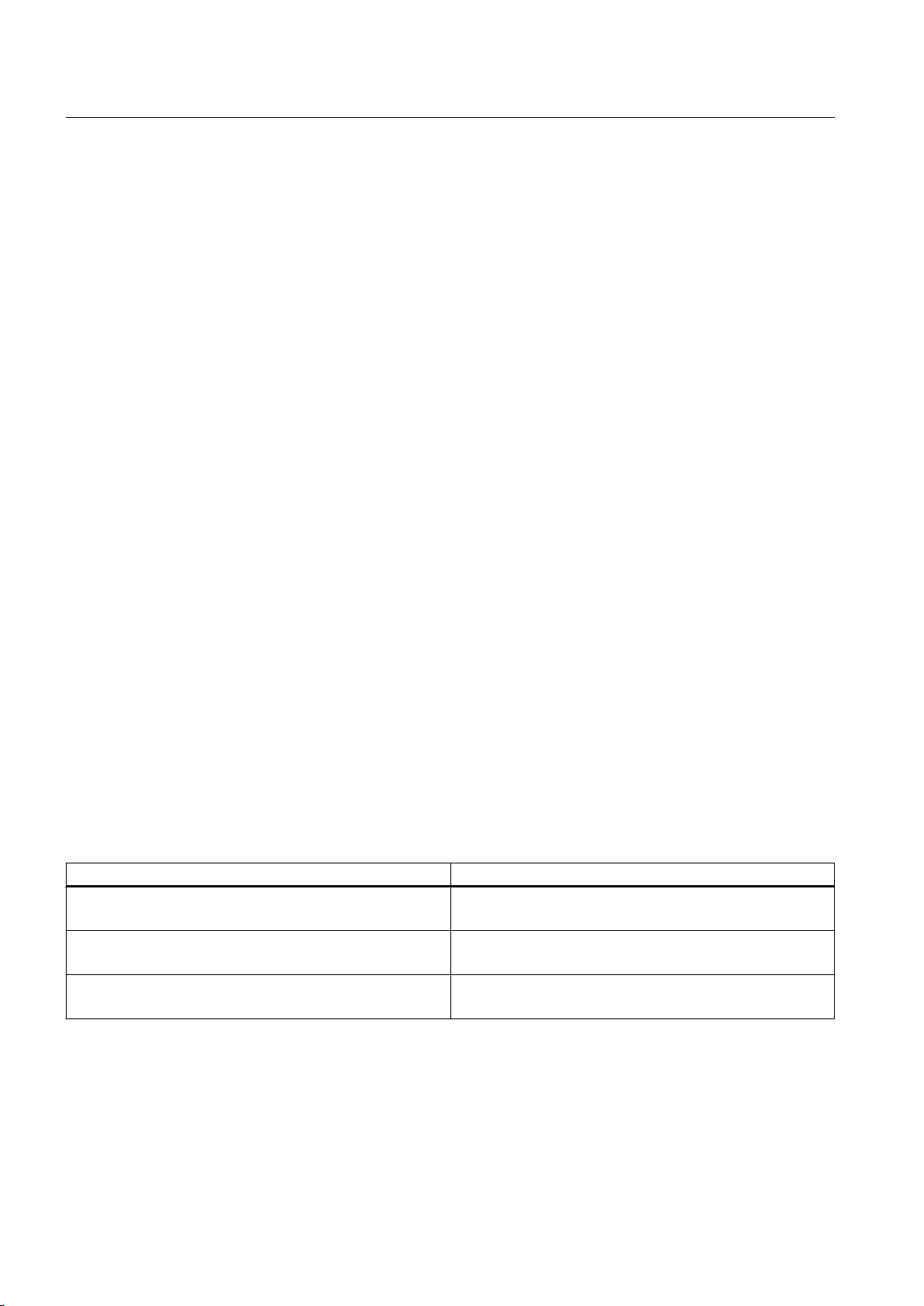
Table 3-3 Setting options for cam output
Selection in configuration screen Setting in expert list
Cam output (CAM)
(TM15/17, D410-2, D4x5-2)
High-speed digital output (DO)
(D4xx, C240)
Standard digital output (DO)
(Standard DO, e.g. ET200, TM31)
OcaBaseCfg.outputType = [1] TIME_STAMP
OcaBaseCfg.hwTimer = [91] NO
OcaBaseCfg.outputType = [0] STANDARD
OcaBaseCfg.hwTimer = [173] YES
OcaBaseCfg.outputType = [0] STANDARD
OcaBaseCfg.hwTimer = [91] NO
Output cams on cam output (CAM) or on high-speed digital output (DO) are also referred to
below as high-speed, hardware-supported output cams.
Output Cams and Measuring Inputs
26 Function Manual, 04/2014
Page 27

Output Cam TO - Part I
3.2 Output cam TO basics
Note
Further information and the output accuracy for high-speed output cams is described in the
PM21 Catalog and in the respective product brief or commissioning/equipment manuals.
Commissioning Manual
Operating Instructions
Commissioning Manual
Commissioning Manual
Commissioning and Hardware Installation Manual
Commissioning and Hardware Installation Manual
Terminal Modules TM15/TM17 High Feature
SIMOTION C2xx
SIMOTION D410
SIMOTION D410-2
SIMOTION D4x5
SIMOTION D4x5-2
See also
Configuring cams on SIMOTION D4xx onboard
(Page 47
)
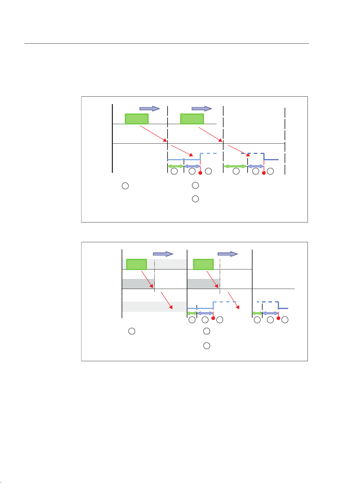
3.2.1.8 Exact time setting of an output, exact time output cams (as of V4.1)
You can switch a high-speed output cam On/Off at an exact time within an execution cycle
(position control, IPO cycle) via the timeOffset parameter of the _setOutputCamState system
function.
Enter an offset of the switching edge in the configured unit (e.g. s) of the Output Cam TO in
the timeOffset parameter. The reference point of the offset is the start of the next execution
cycle of the Output Cam TO. You can read out the value of the time offset (system-dependent
execution time between the execution cycle and the output cycle) in the tOutput system
variable. The time in tOutput is the earliest possible time to switch the output cam. The
timeOffset is added to this time.
Features
● The offset must be less than the cycle time of the processing cycle clock. The offset is
limited automatically and a technological alarm is output when the cycle time is exceeded.
● It is possible to switch on or off within one cycle.
● When this function is used, there is a dependency on the processing cycle clock and the
set cycle clock times.
● The offset is valid for every output cam type. If only switched once, the unidirectional output
cam type is recommended.
● The offset can only be stated if the output cam TO on the outputs is configured with a time
stamp (cam output (CAM)).
● For output cams without time stamp (e.g. C240-2 onboard output cams), tOutput (time
stamp) is set to 0.0.
Output Cams and Measuring Inputs
Function Manual, 04/2014 27
Page 28
6(592
2XWSXW&DP
RXWSXW
'3
7LPHEHWZHHQWKHHQGRI
F\FOHDQGWKHHDUOLHVW
SRVVLEOHRXWSXWWLPH
'LVSOD\HGLQWKHW2XWSXW
V\VWHPYDULDEOH
6LJQDORXWSXW
6SHFLILHG
WLPH2IIVHW
$FWLYDWLRQVLJQDO
HGJH
'HDFWLYDWLRQVLJQDOHGJH
6(592
2XWSXW&DP
RXWSXW
'3
7LPHEHWZHHQWKHHQGRI
F\FOHDQGWKHHDUOLHVW
SRVVLEOHRXWSXWWLPH
'LVSOD\HGLQWKHW2XWSXW
V\VWHPYDULDEOH
6LJQDORXWSXW
6SHFLILHG
WLPH2IIVHW
'36(592
$FWLYDWLRQVLJQDO
HGJH
'HDFWLYDWLRQVLJQDOHGJH
Output Cam TO - Part I
3.2 Output cam TO basics
● If multiple activation or deactivation signal edges are output within one cycle, the most
recently written values apply.
● The start
of the output cycle is shifted with respect to the beginning of the processing cycle
by the value output in the tOutput system variable and the specified timeOffset.
Figure 3-10 Exact-time output setting for DP:POSITION CONTROL=1:1
28 Function Manual, 04/2014
Figure 3-11 Exact-time output setting for DP:POSITION CONTROL=1:2
Output Cams and Measuring Inputs
Page 29
3.2.2 Cam parameters
2&
2&
3RVLWLRQ
EDVHGFDP
3RVLWLRQ[
6WDUWLQJ
SRVLWLRQ
(QGSRVLWLRQ
7LPHEDVHG
RXWSXWFDP
3RVLWLRQ[
6WDUWLQJ
SRVLWLRQ
'XUDWLRQ
3.2.2.1 Reaction, effective direction
Behavior
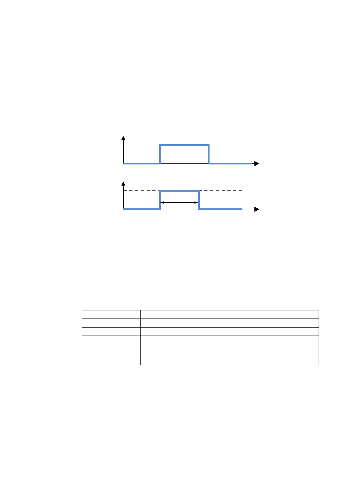
The following diagram shows output cam behavior when switching on and off, without
hysteresis, activation, or deactivation time.
Output Cam TO - Part I
3.2 Output cam TO basics
Figure 3-12 Output cam behavior when switching on/off
The switching action depends on the position only (position setpoint or actual position).
Effective direction
You can define a default effective direction when you activate output cams. The output cam
only switches when the motion direction and effective direction are identical.
Options:
Table 3-4 Effective direction and behavior
Effective direction
Positive The output cam is activated only in positive direction of motion.
Positive and negative The output cam is activated independent of the direction of motion.
Negative The output cam is activated only in negative direction of motion.
Last programmed
direction of rotation
Behavior
With this setting, the output cam switches for the last programmed direction
of rotation. If no direction of rotation has been previously programmed, the
default setting is used.
Output Cams and Measuring Inputs
Function Manual, 04/2014 29
Page 30
3RVLWLRQ
EDVHGFDP
7LPHEDVHG
RXWSXWFDP
3RVLWLRQ
3RVLWLRQ
;
VWDUW
;
VWDUW
;
HQG
$FWXDOSRVLWLRQ
YDOXH
Output Cam TO - Part I
3.2 Output cam TO basics
Figure 3-13 Positive effective direction and output cam switching behavior
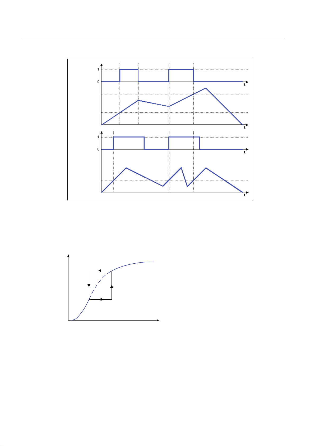
3.2.2.2 Hysteresis
If the actual position value tends to fluctuate due to mechanical influences, specification of a
hysteresis prevents the output cam from unintended switch status changes.
Figure 3-14 Hysteresis
Hysteresis range conditions
Hysteresis is not activated until the direction has been reversed.
●
30 Function Manual, 04/2014
● The direction of motion is not redefined within the hysteresis.
Output Cams and Measuring Inputs
Page 31
+\VWHUHVLV
$FWXDOSRVLWLRQRID[LV
;
VWDUW
6ZLWFKLQJVWDWHRISRVLWLRQEDVHGFDP
Output Cam TO - Part I
3.2 Output cam TO basics
● Within the hysteresis, the switching state of position-based cams is not changed.
● If modified switching conditions for the output cam are detected when the output cam is
outside the hysteresis range, this current switching state is set.
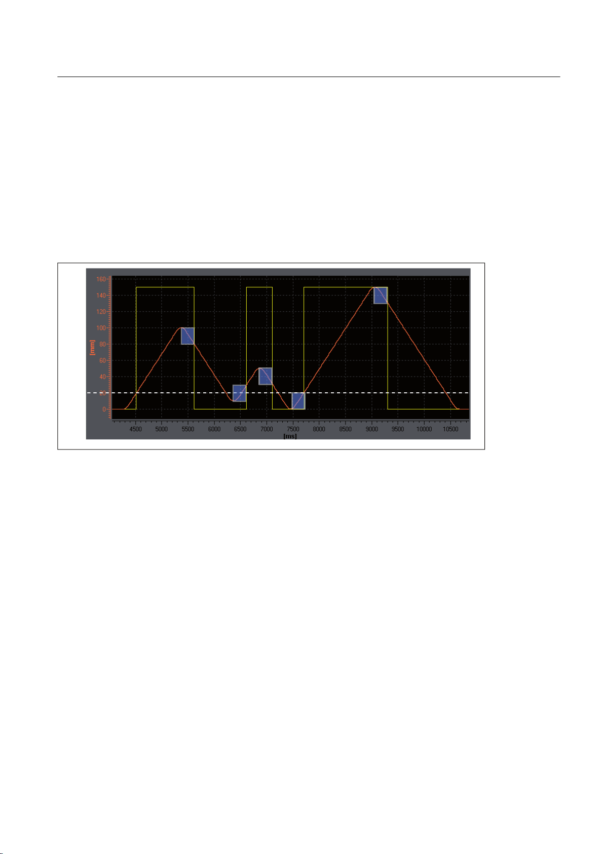
Example: position-based cam hysteresis
Output cam configuration:
output
cam type: position-based cam; switch-on position, 20 mm; switch-off position, 200 mm;
hysteresis, 20 mm; effective direction: positive
Axis positions:
0 mm -> 100 mm -> 10 mm -> 50 mm -> 0 mm -> 150 mm -> 0 mm
Figure 3-15 Hysteresis range (height of blue sections) and behavior of a position-based cam, positive effective direction
Output
second switch-on point is moved to position 30 mm, due to hysteresis (see figure
cam's
above).
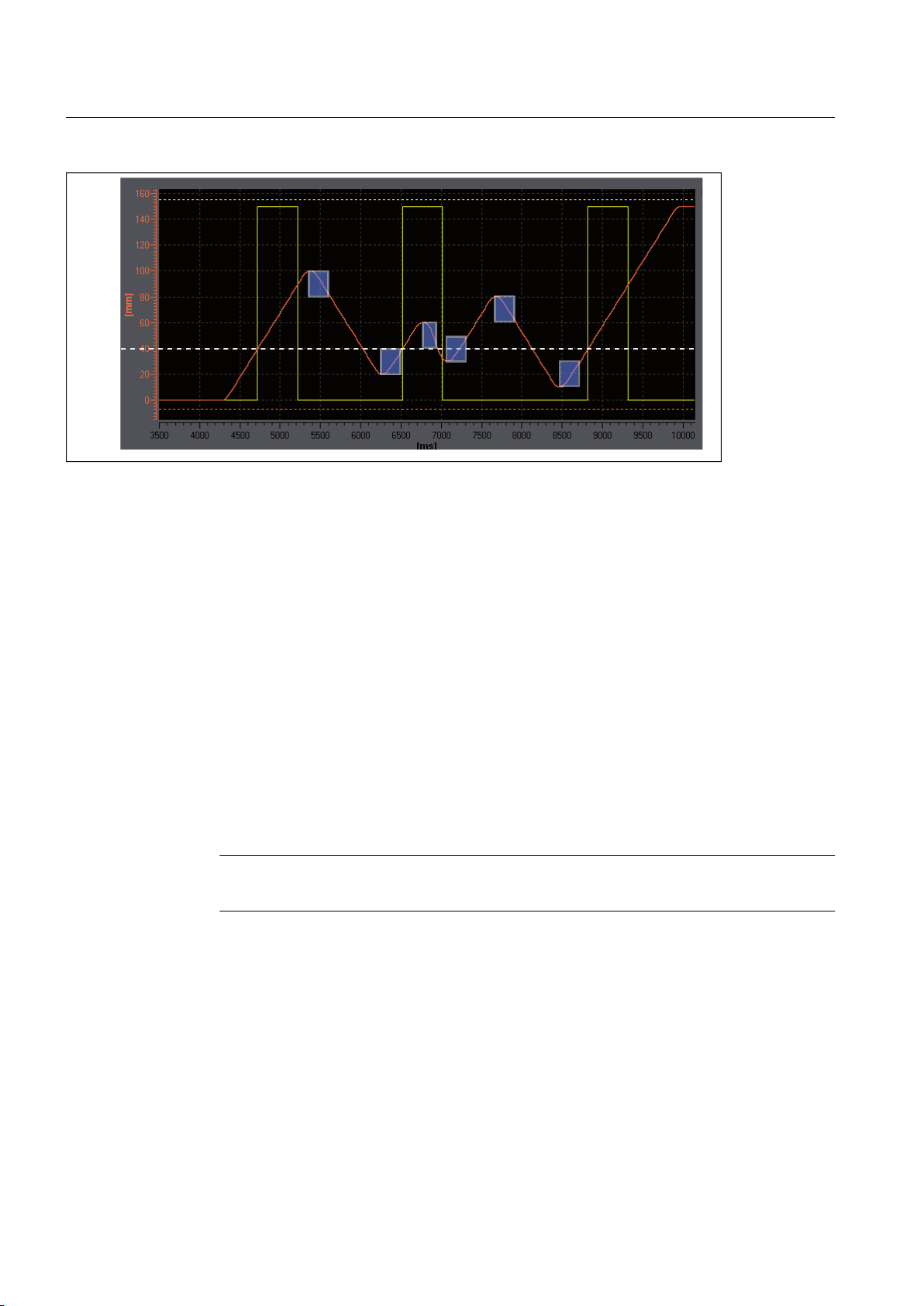
Example: time-based cam hysteresis
Output cam configuration:
output cam type: time-based cam; switch-on position, 40 mm; ON duration, 0.5 s; hysteresis,
20 mm; effective direction: positive
Axis positions:
0 mm -> 100 mm -> 20 mm -> 60 mm -> 30 mm -> 80 mm -> 10 mm -> 150 mm
Output Cams and Measuring Inputs
Function Manual, 04/2014 31
Page 32
+\VWHUHVLV
$FWXDOSRVLWLRQRID[LV
;
VWDUW
6ZLWFKLQJVWDWHRIWLPHEDVHGFDP
2XWSXWFDP
GRHVQRWVZLWFK
Output Cam TO - Part I
3.2 Output cam TO basics
Figure 3-16 Hysteresis range (height of blue sections) and behavior of a time-based cam, positive effective direction
Time-based cam
switches off only after ON duration has expired, not after change of direction.
Time-based cam with a start position within the hysteresis range is not output (see figure
above).
Hysteresis range
The upper limit of the hysteresis range is set at 25% of the working range for a linear axis, and
25 % of the rotary axis range for a rotary axis. If you violate this maximum setting, an error
message is issued. In practice, a lower setting is used for the hysteresis range.
● Path-controlled output cam
The hysteresis becomes active after direction reversal is detected. If only a positive or only
a negative effective direction has been parameterized for an output cam, the output cam
does not switch off after a reversal of direction until it has left the hysteresis.
● Time-based cam
The switching behavior of a time-based cam is determined by the ON duration, not by the
hysteresis. This means that an entered hysteresis range has no influence on the ON
duration of an output cam. It only has an influence on the switch-on time (start position).
Note
If a time-based cam's start position lies within the hysteresis, it is not output.
3.2.2.3
Derivative-action times (activation/deactivation time)
To compensate for the switching times of digital outputs and connected switching elements,
of propagation delays, it is possible to specify actuation times. Actuation times are calculated
or
from the sum of all delay times and can be specified separately for activation and deactivation
edges as an actuation time at the activation edge (activation time) or an actuation time at the
deactivation edge (deactivation time).
32 Function Manual, 04/2014
Output Cams and Measuring Inputs
Page 33
'HDFWLYDWLRQWLPH
$FWLYDWLRQWLPH
'HDFWLYDWLRQWLPH
$FWLYDWLRQWLPH
Output Cam TO - Part I
3.2 Output cam TO basics
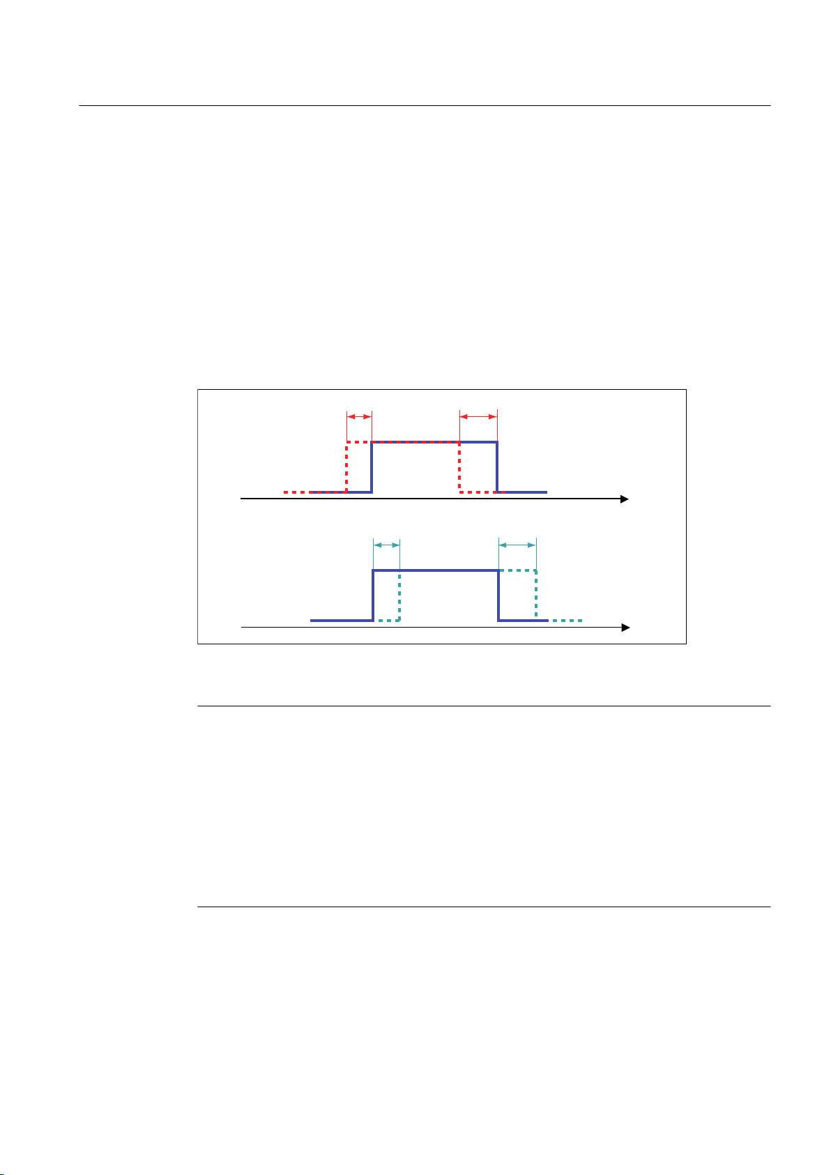
The activation/deactivation times of the TO outputCam are dynamically compensated by
means of the derivative-action times. In this way, output cams are dynamically shifted
depending on the actual velocity.
For example, a valve that should open at 200°, with an activation time of 0.5 s
● Must be controlled at 195° at a velocity of 10°.
●
Must be controlled at 190° at a velocity of 20°.
This dynamic shift takes place automatically by means of the Output Cam TO.
Settings for the activation and deactivation times can contain positive or negative values.
A negative activation time must be entered if the output cam is to be switched before the
programmed start of the output cam.
Figure 3-17 Switching behavior at varying actuation times
Note
The time
of output for the output cam in the controller is relevant for calculation of the dynamic
adjustment. If velocity changes up to signal output, these changes are no longer taken into
account.
Dead times, e.g. PROFIBUS DP communication times, output delay times on digital outputs,
etc., are taken into account in the actuation time.
Long actuation times exceeding one modulo cycle may lead to heavy fluctuation of the
switching position of actual value output cams (actual value curve). Here, setpoint output
cams should be used or the actuation time should be considerably less than one modulo
cycle.
The system takes into account the specified actuation times when the output cams are
calculated and
managed. The switching positions of the output cams are calculated taking into
account the activation time and deactivation time in relation to the present velocity. If, allowing
for actuation times, the output cam was switched, then the system deems this operation to
have occurred, and it does not switch the output cam again even if any subsequent current
velocity changes occur.
Output Cams and Measuring Inputs
Function Manual, 04/2014 33
Page 34

Output Cam TO - Part I
3.2 Output cam TO basics
The dynamic actuation of modulo axes can be greater than one modulo length. However, the
number of switching operations is not collected by the system, i.e. for actuation times longer
than one modulo length, a switching operation cannot take place in each modulo cycle. One
switching operation
completed when the output cam is switched off.
Actuation times and cycle clock settings
A change of cycle clock settings does not have to be taken into account for the actuation time
settings (activation/deactivation time). These are, for example:
● Changing the Servo/IPO/IPO_2 clock settings (for example, from "1/1/1 ms" to "2/2/2 ms").
● Change of processing cycle clock of the TO outputCam (setting: Servo cycle clock, IPO
cycle clock, IPO_2 cycle clock).
Deactivation time for time-based cam
Deactivation time is also taken into account in setting a time-based cam.
Deactivation time must be:
is active in the system at any given point in time. A switching operation is
● Deactivation time ≤ activation time + ON duration
Activation and deactivation times can vary independently of the I/O and can, therefore,
influence the ON duration of the time-based cam.
To achieve compatibility with older software versions (<V3.2), deactivation time for time-based
cams can be activated or deactivated in the Defaults window, by means of the Use deactivation
time checkbox.
See also
Determining derivative-action times for output cams (dead time compensation) (Page 45)
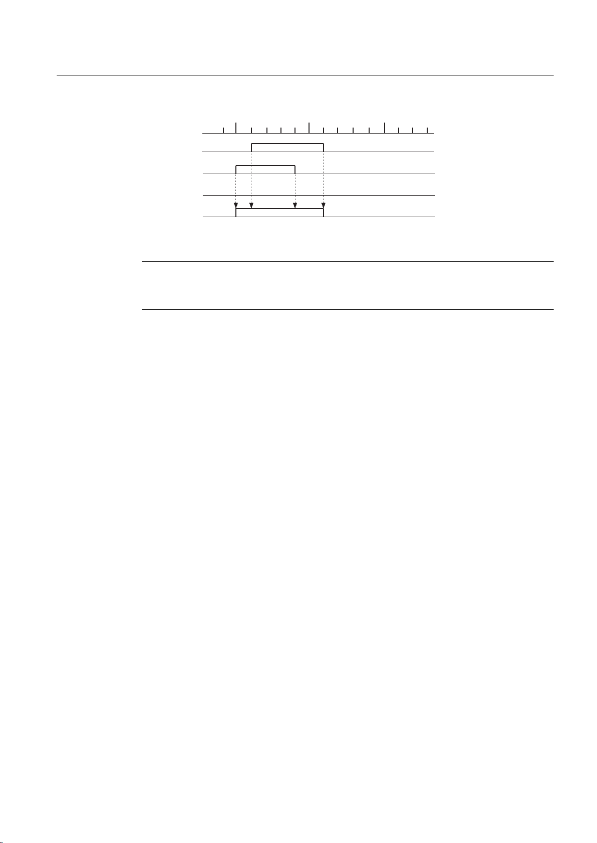
3.2.2.4 Logical operation
Through a setting in the LogAdress.logicOperation configuration data element you can specify
whether the output cam is connected to the output using an AND or OR operation.
That is, all ORed output cams will be grouped and then logically linked at the output with the
output cams linked by AND logic.
Output Cams and Measuring Inputs
34 Function Manual, 04/2014
Page 35
PPPP
PP
[
2XWSXW
FDP
2XWSXW
FDP
2XWSXW
See also
Output Cam TO - Part I
3.2 Output cam TO basics
Figure 3-18 OR operation of two output cams
Note
If hardware output cams are configured, you can configure an I/O variable in the symbol
browser for monitoring.
Output cam configuration (Page 38)
3.2.2.5
Simulation
Operation can be simulated by means of the simulation commands on the output cam. The
output cam status is then not output to the hardware output. In simulation mode, a hardware
cam behaves as a software cam. It is then only used for programming purposes.
If an active output cam is switched to simulation mode (_enableOutputCamSimulation), the
output cam status remains the same, and only the control of the output is reset or interrupted.
3.2.2.6 Inversion
The inversion of single output cams is available and is set on the _enableOutputCam command
by a parameter (invertOutput).
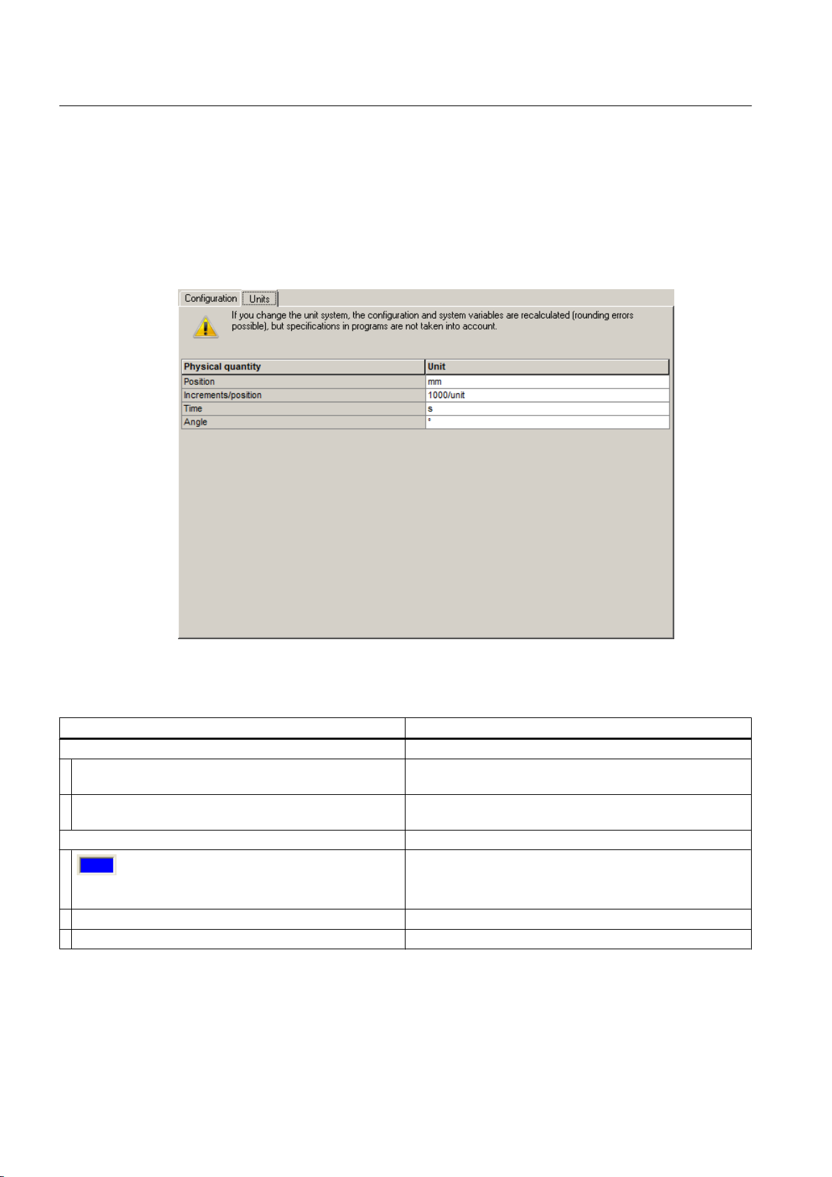
3.2.3 Configure Units
You can define the basic units for each technology object. The same physical variables can
have different units in different technology objects. These are converted:
How to configure the units:
1. In the project navigator, open the context menu for the technology object.
2. In the context menu, select Expert > Configure units. The Configure Units window appears
in the working area.
3. Select the unit for the physical variables. These units are used for the technology object,
e.g. s for time units.
Output Cams and Measuring Inputs
Function Manual, 04/2014 35
Page 36
Output Cam TO - Part I
3.2 Output cam TO basics
or
1. In the project navigator, open the Configuration under the TO.
2.
Select the Units tab.
You can set the following parameters:
Field/button Meaning/instruction
Table with units
Physical variable column Shows the physical variable. The physical variables which
are used by the TO are available for the configuration.
Unit column Displays and configures the unit. A drop-down list for
selecting the unit appears when you click on the cell.
Toolbar
Close Button for closing the dialog.
Help Button for opening the online help for the dialog.
Displays whether offline data or online data is shown
● Blue field = offline display
Yellow field = online display
●
Output Cams and Measuring Inputs
36 Function Manual, 04/2014
Page 37

3.3 Configuring the Output Cam technology object
3.3 Configuring the Output Cam technology object
3.3.1 Insertion of Output Cam
Note
Output Cam TO - Part I
Before you
insert an output cam, the axis (position or synchronous axis) or external encoder
to which the output cam is assigned has to be created.
If the output cam is to be output to a TM15/TM17 High Feature module, the module must be
inserted and configured before the output cam configuration.
To insert a new output cam:
1. In the project navigator, highlight the OUTPUT CAMS
external encoder.
2. Select Insert > Technology object > Output cam or double-click Insert output cam in the
project navigator under the axis or external encoder in the OUTPUT CAMS folder. The
Insert output cam window appears.
3. Enter a name for the output cam. You can also enter a comment.
Names must be unique throughout the project and must comply with ST syntax conventions.
For this reason, all the existing output cams are displayed under Available output cams.
4. Click OK to confirm. In the working area, the window for the configuration is displayed and
the created output cam TO is shown in the project navigator.
3.3.2 Parameterize Output Cam technology object
folder under the relevant axis or
General information about configuration data and system variables
Two data classes are distinguished when parameterizing a TO.
Configuration data defines the principal functionality of a TO. They are set within the object
configuration framework with the SCOUT engineering system and are not normally changed
during runtime.
System variables provide status data of the TO for the user program and a parameterization
Output Cams and Measuring Inputs
Function Manual, 04/2014 37
interface on the TO. System variables can be changed during runtime.
Note
You will find more information on technology objects in the
Functions functional description
.
SIMOTION Runtime Basic
Page 38

Output Cam TO - Part I
3.3 Configuring the Output Cam technology object
To parameterize an output cam:
1. In the
project navigator under the folder OUTPUT CAMS, find the output cam TO that you
want to parameterize. Double-click the output cam TO to display the associated objects.
2. Double-click Configuration or Default in the project navigator. The window appears on the
workspace.
– Configuration:
Define the configuration data of the output cam here. This includes, for example, output
cam type.
– Default:
Define the output cam defaults of the system variables here. This includes, for example,
the effective direction.
3. Change the configuration data and output cam defaults.
4. Click Close to accept the changes.
5. Repeat steps 2 to 4 for all objects in which you want to change the configuration data and
output cam defaults.
See also
Output cam configuration (Page 38)
Defining output cam defaults (Page 43)
3.3.3 Using the expert list for output cams
For standard SIMOTION applications, necessary parameters (configuration data and system
variables) are parameterized into the Output Cam technology object directly in screen forms
or are defined automatically.
It may be necessary to change automatically defined parameters for special SIMOTION
applications. These configuration data and system variables can only be displayed and
changed in the expert list.
Note
You will
find more information on working with the expert list in the
Functions functional description
.
SIMOTION Runtime Basic
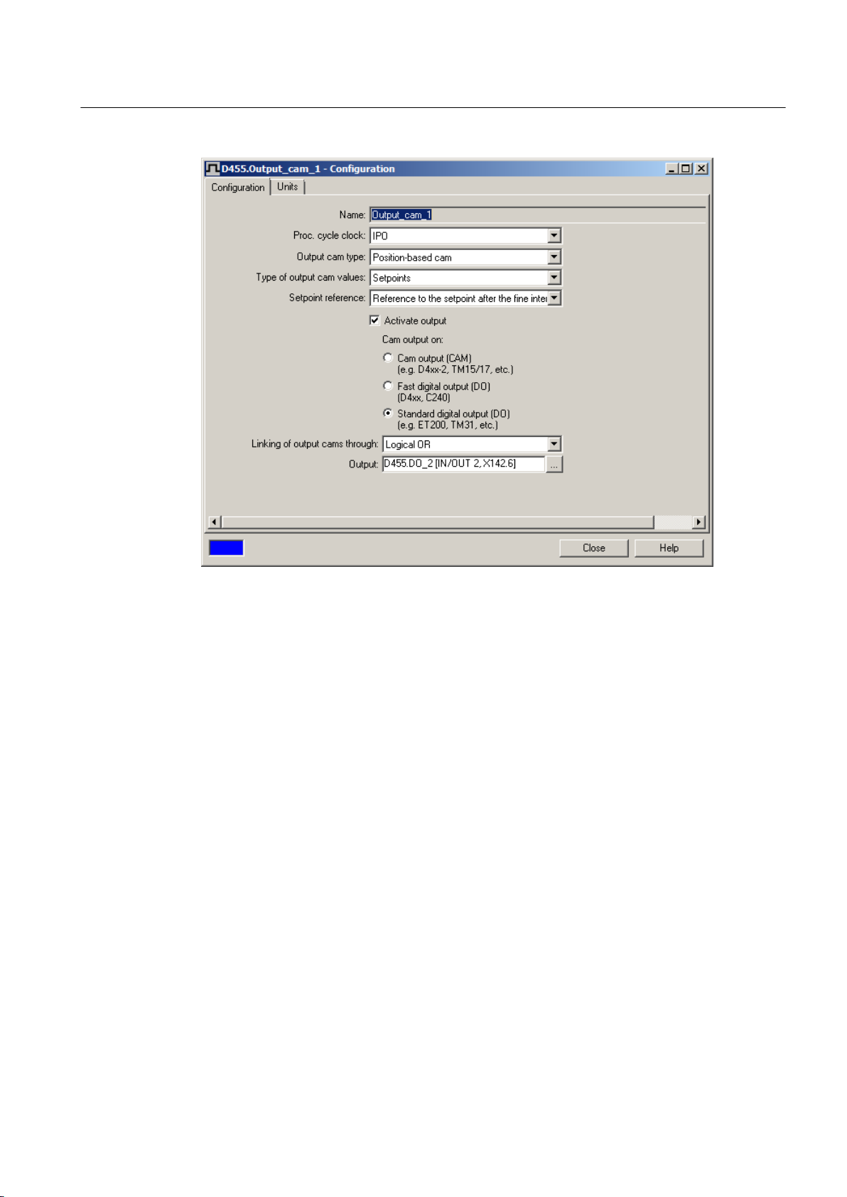
3.3.4 Output cam configuration
Configuration window, define the configuration data values for the output cam.
In the
Double-clicking in the project navigator below the output cam on the Configuration element
displays the window in the working area.
Output Cams and Measuring Inputs
38 Function Manual, 04/2014
Page 39
Output Cam TO - Part I
3.3 Configuring the Output Cam technology object
Figure 3-19 Output cam configuration using the example of a position-based cam
Output Cams and Measuring Inputs
Function Manual, 04/2014 39
Page 40
Output Cam TO - Part I
3.3 Configuring the Output Cam technology object
Figure 3-20 Assignment dialog
You can set the following parameters:
Table 3-5 Output cam configuration data
Field/button Meaning/information
Name The name of the created output cam is displayed here.
Output cam type Choose Output cam type to select the type of output cam.
Position-based cam
(default value) The switching signal is active when the position of the axis lies between two
markers (start and end position).
Time-based cam
The switching
position).
Uni-directional output cam
The switching signal changes when the axis reaches the switching position (start position). The
output cam remains switched on even if the start position is overtraveled several times. The
output cam must be explicitly reset.
signal is on for a specific period of time after reaching the switching position (start
Output Cams and Measuring Inputs
40 Function Manual, 04/2014
Page 41

Output Cam TO - Part I
3.3 Configuring the Output Cam technology object
Field/button Meaning/information
cycle
Processing cycle clock Choose Processing
signal at the output or in the system variables.
The cam calculations are performed in IPO or IPO_2 cycles or in servo cycles. The processing
cycle clock is set in the configuration by means of the OcaBaseCfg.taskLevel configuration data
element.
IPO
(default value)
The output cam signal is updated in the interpolator cycle clock.
IPO_2
The output cam signal is updated in the interpolator cycle clock 2. The IPO_2 cycle clock length
is at least twice that of the IPO.
Servo
The output cam signal is updated in servo cycles.
The following configurations of the processing cycle clock are possible:
● Axis in IPO cycles and output cam in IPO_2 cycles
● Output cam in servo cycles and axis in IPO or IPO_2 cycles
For the possible setting of IPO_fast and Servo_fast with D435-2, D445-2 and D455-2, see
Section Second servo cycle clock (Servo_fast) in the SIMOTION Runtime Basic Functions
Manual.
Note:
● It is not possible to configure the axis in the servo cycle clock and the output cam in the IPO
or IPO_2 cycle clock.
● It is not possible to configure the axis in the IPO cycle clock and the output cam in the IPO_2
cycle clock if it is a setpoint output cam.
● It is not possible to configure the axis in the IPO_2 cycle clock and the output cam in the IPO
cycle clock.
Type of output cam value Select the position value that is the reference for the output cam during processing.
Actual value reference Select the following settings here depending on the type of the output cam values:
to
● Reference
position in the controller before the position filter.
● Reference to the actual value after the position filter. Reference to the actual position in the
controller after the position filter.
● Reference to the actual value on the encoder. Ti is considered. Reference to the actual value
on the encoder module / drive. The transmission time Ti from the encoder module / drive to
the controller is taken into account by the system.
Setpoint reference Select the following settings here depending on the type of the output cam values:
● Reference to
as if the setpoints will already have been reached at the end of this IPO cycle, e.g. if a setpoint
is calculated for the IPO cycle clock with the virtual axis and also displayed at the end of the
cycle. Reference is made directly to the setpoint applicable at the end of the cycle.
● Reference to the setpoint after the fine interpolator. The cam switch points are calculated as
if the setpoint calculated in the interpolator will be output completely in the following cycle
and the calculated position setpoint will therefore be reached at the end of the following cycle.
● Reference to the setpoint on the drive. Calculation of the cam switch points according to the
setpoint output with the current settings on the drive.
Activate output Activate the checkbox if the output cam signal is to be applied to a digital output. Parameters
are displayed.
the actual value on the encoder without considering Ti. Reference to the actual
the setpoint before the fine interpolator. The cam switch points are calculated
clock to select the system cycle clock used to update the output cam
Output Cams and Measuring Inputs
Function Manual, 04/2014 41
Page 42

Output Cam TO - Part I
3.3 Configuring the Output Cam technology object
Field/button Meaning/information
Cam output on
Cam output (CAM) If the output checkbox is activated and the cam output (CAM) radio button selected, the cam
output is on the basis of an internal time stamp.
temporal resolution of the cam output depends on the hardware used. In the case of D4x5-2
The
and the TM17 High Feature, the resolution is, for example, 1 µs.
Supported hardware:
● SIMOTION D410-2
● SIMOTION D4x5-2 (X142)
● TM15, TM17 High Feature
The I/O channel must be configured as CAM.
For more details, see cam output types. (Page 22)
Note
Cam output (CAM) or high-speed digital output (DO) are also known as high-speed, hardware-
supported output cams.
High-speed digital
output (DO)
Standard digital
output (DO)
Logical operation
(Page 34)
If the output checkbox is activated and the "High-speed digital output (DO)" radio button selected,
the output
timer and the cam output is achieved with a resolution with respect to time < servo cycle clock.
The time that it takes for the axis to reach the output cam switching position with reference to
the processing cycle is calculated by linear extrapolation. Calculated from the beginning of the
1st position control cycle, the output cam function is triggered by a hardware time when this time
is reached.
Supported hardware:
The onboard I/O of the following CPUs is used:
● SIMOTION D4x5 (interface X122, X132), 8 high-speed cam outputs, as of V4.1 (the I/O
● SIMOTION D410 (interface X121), 4 high-speed cam outputs, as of V4.1 (the I/O channel
● SIMOTION C240, C240 PN (interface X1), 8 high-speed cam outputs
For more details, see cam output types. (Page 22)
Note
Cam output (CAM) or high-speed digital output (DO) are also known as high-speed, hardware-
supported output cams.
If the output checkbox is activated and the "Standard digital output (DO)" radio button selected,
the output cam is output in the servo cycle clock.
The temporal
Supported hardware:
● Onboard outputs (SIMOTION D, Controller Extension CX, SINAMICS Control Unit CU3xx)
● Centralized I/O (SIMOTION C)
● Distributed I/O via PROFIBUS DP / PROFINET IO (e.g. ET 200, etc.)
● Drive I/O TM15, TM15 DI/DO, TM17 High Feature, TM31, TM41, TB30
For more details, see cam output types. (Page 22)
You can assign several TO output cams to an output. Select the logical link of the output cam
signal with the output. During the operation, all output cam signals are first grouped together
with the
signals to which a logical AND was assigned.
cam is output via onboard outputs of the SIMOTION CPU. The output is via a hardware
channel must be configured as DO)
must be configured as DO)
resolution of the cam output is usually reduced by the output cycle of the I/O used.
logical operation OR. The result of this operation is then combined with the output cam
Output Cams and Measuring Inputs
42 Function Manual, 04/2014
Page 43
Output Cam TO - Part I
3.3 Configuring the Output Cam technology object
Field/button Meaning/information
Output The output can be symbolically assigned via the assignment dialog (see Section Symbolic
assignment (as of V4.2) in the SIMOTION Runtime Functions Manual) using the
the Output field (symbolic assignment is activated by default in projects as of V4.2).
If symbolic
by entering the HW address and bit number in the Output field.
Enter the logical HW address of the output to which the output cam signal is to be applied. Only
the output cam signal may be present at this address. If other objects are already using this
output, an error occurs that is reported following a download to the target system. The logical
HW address must be located outside the process image and therefore be greater than 63.
For more details, see cam output types. (Page 22)
Button for opening the assignment dialog (see Section Symbolic assignment (as of V4.2) in the
SIMOTION Runtime Basic Functions Manual). Select a parameter or an address in the
assignment dialog.
Displays whether offline data or online data is shown
● Blue field = offline display
●
assignment is not active or if the CPU version is < V4.2, a physical output is assigned
Yellow field = online display
button in
3.3.5 Defining output cam defaults
You can
and can be changed by programs.
Double-clicking in the project navigator below the output cam on the Defaults element displays
the window in the working area.
define the defaults for every output cam. These values are stored in system variables
Output Cams and Measuring Inputs
Function Manual, 04/2014 43
Page 44
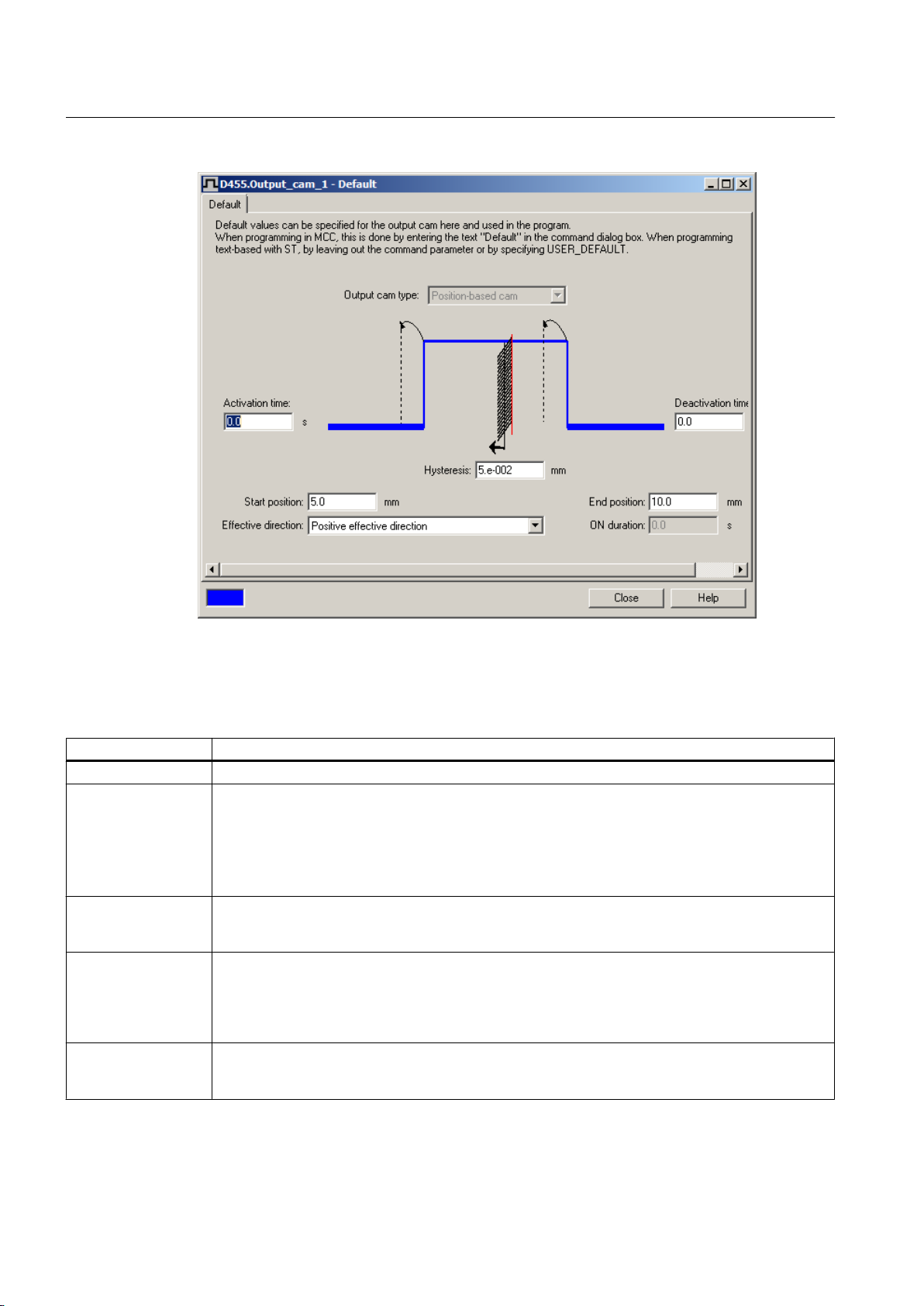
Output Cam TO - Part I
3.3 Configuring the Output Cam technology object
Figure 3-21 Output cam defaults, position-based cam example
You can set the following parameters:
Table 3-6 Defining output cam defaults
Field/Button Significance/Note
Output cam type Output cam type displays the type of output cam selected in the Configuration window.
Activation time
See also the
Actuation times
(activation/
deactivation time)
section.
Using deactivation
time
Deactivation time Enter the deactivation time here. The output cam switch-off time is set to the point when the end
Hysteresis Enter a range for the hysteresis here. The output cam does not change its switching state in this
Enter the activation time
is reached, plus this period. The output cam position is adapted dynamically. This allows you to
compensate for propagation delays.
If a negative value is entered as an activation time, the switching signal is activated before the start
position is reached.
Activate the checkbox if you want to use a deactivation time when working with time-based cams. If
this checkbox is deactivated, you cannot enter a time. In this respect, the time-based cam is
compatible with older software versions (<V3.2).
position is reached, plus this period. The output cam position is adapted dynamically. This allows
you to compensate for propagation delays.
a
negative value is entered as a deactivation time, the switching signal is activated before the end
If
position is reached.
defined range
a repeated change of the switching state.
around the switching position even under changed switching conditions. This prevents
here. The output cam switching time is set to the point when the start position
Output Cams and Measuring Inputs
44 Function Manual, 04/2014
Page 45

Output Cam TO - Part I
3.3 Configuring the Output Cam technology object
Field/Button Significance/Note
Start position
See also the Output
cam types section.
End position Enter the end position of the output cam. For path-controlled output cams this is the right switching
Effective direction Enter the effective direction
ON duration Enter the ON duration for time-controlled output cams here. After the axis has passed the switch-on
Enter the start position of the output cam. For path-controlled output cams this is the left switching
position.
position.
the output cam. The output cam is active only if the current direction
for
of motion of the axis corresponds to the parameterized effective direction.
Positive and negative effective direction (both)
Output cam switches in both directions of motion
Last programmed effective direction (effective)
Output cam switches only in the last programmed effective direction
Negative effective direction (negative)
Output cam switches only for negative direction of motion
Positive effective direction (positive)
Output cam switches only for positive direction of motion
position, the time-based cam output remains on for the ON duration.
See also
Derivative-action times (activation/deactivation time) (Page 32
Reaction, effective direction (Page 29)
Hysteresis (Page 30)
)
3.3.6 Determining derivative-action times for output cams (dead time compensation)
Depending on the system and the device, there is a certain time between the setting of a cam
output by the program and the actual reaction of the actuator (e.g. solenoid valve). This time
is called dead time and depends, for example, on the load-dependent delay times of a digital
output, the switching properties of a valve, etc. Usually the exact value for the dead time is not
known and can therefore be determined empirically through measurements.
In order that an output cam switches at the correct time, the dead time must be compensated
by specifying a derivative-action time, which offsets the cam output by the dead time. Whereby
it must be taken into account that the derivative-action times for switching an actuator on and
off are usually different.
The empirical determination of the dead times using a difference measurement as an example.
Note
The procedure applies not only to output cams, but also to cam tracks. However, with cam
tracks you can only specify a derivative-action time for the entire cam track.
Output Cams and Measuring Inputs
Function Manual, 04/2014 45
Page 46
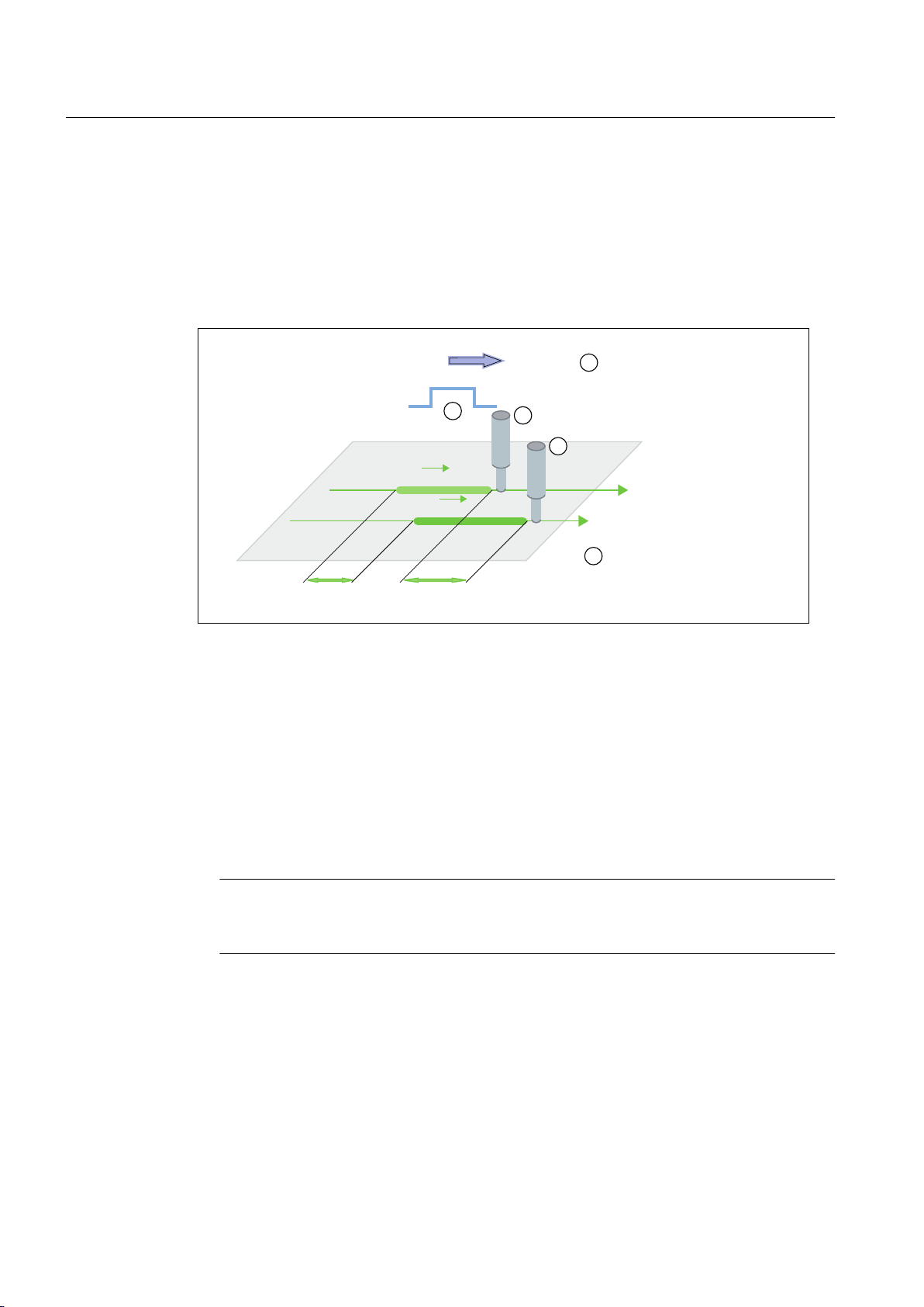
;$
;$
;(
;(
˂;$
˂;(
9
9
*OXHDSSOLFDWLRQWRSURGXFWYLD
JOXHQR]]OHV6KRZQZLWK
GLIIHUHQWYHORFLWLHV99
2XWSXWFDPFRQWUROVVWDUWDQG
HQGSRLQWVRIJOXHDSSOLFDWLRQ
Output Cam TO - Part I
3.3 Configuring the Output Cam technology object
Example
Lines of glue are to be applied to a product at a defined position and with a fixed length. The
glue output
is controlled by an output cam or a cam track. The glue is output from the start of
output cam (switch-on point) to the end of output cam (switch-off point). The offset of the begin
and end of output cam with respect to the velocity can be observed on the length and position
of the glue line on the product (see figure). The figure below shows the line of glue for two
velocities (v1, v2) with v2 > v1.
Figure 3-22 Offset of the output of output cam through dead times (dead time compensation)
Procedure:
1. Set all actuation times for start of output cam (activation time) and end of output cam
(deactivation time) to 0.
2. Define the velocities for which the positions are to be determined. You should select two
velocities that correspond to velocities that occur during production (e.g. minimum and
maximum velocity).
3. Start the application and determine the start positions (xA1 and xA2) and end positions (xE1
and xE2) of the line of glue for the velocities v1 and v
Note
2.
To increase the accuracy, you can perform several comparison measurements and use
the average measured values.
4. You can determine the actuation times for the output of output cam using the following
formula.
t
= Δs/Δv = (xA2-xA1)/(v2-v1)
activation
t
deactivation
= Δs/Δv = (xE2-xE1)/(v2-v1)
Output Cams and Measuring Inputs
46 Function Manual, 04/2014
Page 47

Output Cam TO - Part I
3.3 Configuring the Output Cam technology object
5. Enter the calculated actuation times as activationtime for the start of output cam and as
deactivationtime for the end of output cam. Note that the actuation time must be entered
as a negative when the output time is to be before the programmed output cam switching
time.
6. After you have determined the activation time and the deactivation time for the output of
output cam, you should perform a control measurement and check the result.
Note
Depending on
the application, it may be, e.g. with eccentric presses, that there is no linear
relationship between dead time and velocity (e.g. non-linear response of an applied
brake). You have to dynamically adapt the dead time to the respective velocity for these
applications. This can be implemented in the application with a user program. After the
actuation time has been changed, you have to activate the output cam again with
_enableOutputCam or the cam track with _enableCamTrack.
See also
Derivative-action times (activation/deactivation time) (Page 32)
3.3.7
Configuring cams on SIMOTION D4xx onboard
Output cams and cam tracks can be configured for standard outputs, or as high-speed,
hardware-based output cams / cam tracks.
Cams can be configured on SIMOTION D4xx onboard as follows:
1. In the project navigator, switch to the Control Unit via SINAMICS_Integrated > Control_Unit.
2. Double-click Inputs/outputs below the control unit. The window appears on the workspace.
3. Switch to the Bidirectional digital inputs/outputs tab.
Output Cams and Measuring Inputs
Function Manual, 04/2014 47
Page 48
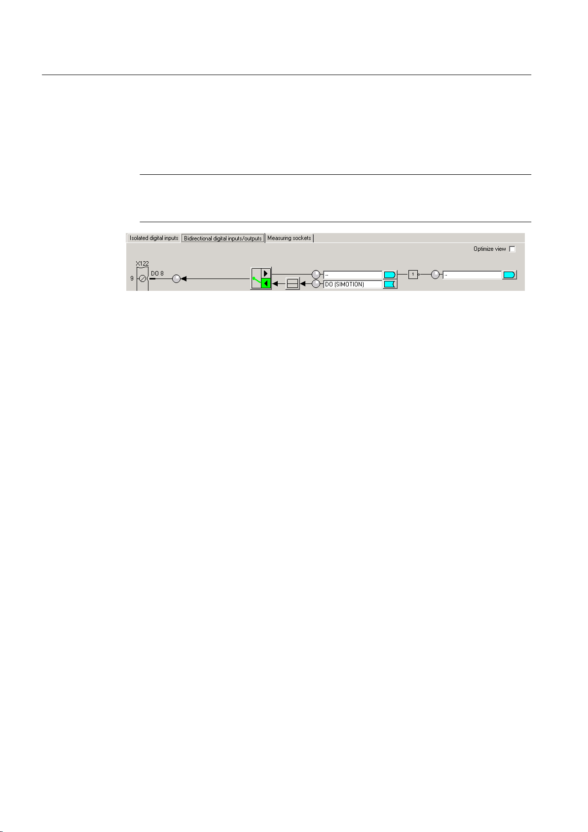
Output Cam TO - Part I
3.3 Configuring the Output Cam technology object
4. Click the button to switch between the input and output for the digital inputs/outputs (DO8
to DO15). In each case, switch the DI/DO to the output you wish to use as the output of
output cam. The designation at the terminal strip of DI or DO switches to DO. Outputs of
the output
as an output in the diagram. For the output, select the DO (SIMOTION) setting.
Note
cam can only be used if they have been defined as an output. DO 8 is configured
Mixed use
of the SIMOTION D4xx DI/O as high-speed outputs (of output cams) and inputs
of measuring inputs is possible.
Figure 3-23 SIMOTION D4xx digital inputs/outputs
5. Click
Close.
6. Insert a new output cam or a new cam track or use an existing one.
7. Parameterize the TO Output Cam / Cam Track
8. Double-click Configuration below the output cam or the cam track in the project navigator.
The Configuration window appears in the working area.
9. For high-speed, hardware-supported output cams, you can achieve an output accuracy
exceeding the servo cycle clock based on the hardware used. Should you wish to configure
a high-speed output cam, select the Activate output check box and select the High-speed
digital output (DO) radio button.
10.Assignment of an output to an output cam/cam track is supported as of V4.2 either by
symbolic assignment (see Chapter Symbolic Assignment (as of V4.2) in the SIMOTION
Runtime Basic Functions manual) or by entering the hardware address.
11.Click OK to close the window and select Project > Save.
To determine the logical hardware address for outputs on SIMOTION D4xx onboard (only if
symbolic assignment is not activated)
1. In the project navigator, below the SIMOTION D device, select SINAMICS_Integrated >
Communication > Telegram configuration.
2. Double-click Configuration and, in the window which appears, select the tab IF1:
PROFIdrive PZD telegram. The components are displayed there with address range (input/
output data).
Output Cams and Measuring Inputs
48 Function Manual, 04/2014
Page 49
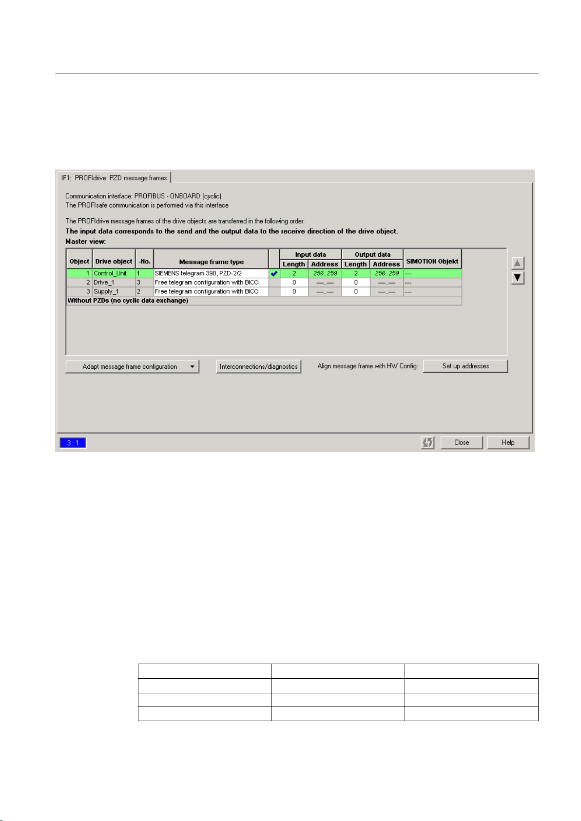
Output Cam TO - Part I
3.3 Configuring the Output Cam technology object
3. Select SIEMENS telegram 390, 391 or 392 as telegram type. A maximum of eight output
cams can be configured for each telegram. The number of DI/DO is limited to eight, i.e.
only two output cams can be configured for telegram 392 if you are already using six
measuring inputs. Therefore consider whether you also want to use measuring inputs
during the telegram selection.
Figure 3-24 Determining the hardware address of the components
4. Before you determine the hardware address, an alignment between HW Config and
SIMOTION SCOUT, with respect to the address, must be performed. If this has not been
performed or you have changed the addresses, click on Set up addresses. If there are
question marks in the fields instead of I/O addresses, you must also perform an alignment.
5. Now calculate the hardware address by adding the base output address (first value of the
output data) of the Control Unit to the offset (for example 298 + 3 = 301). The offset always
has the value 3. Enter this calculated address under Measuring input > Configuration >
Input (e.g. PI 301.1)."]
6. The onboard measuring inputs in the expert list of the Control Unit must be set in parameters
680[0] to 680[5] (e.g. 680[0] -> [1] DI/DO 9 (X122.8/X121.8))." You will find the bit number
in the following table. The inputs are set in parameters 680.0 to 680.7 of the Control Unit,
e.g. bit 1 in parameter 680[0].
Table 3-7 Bit numbers for D410 and D4x5
Output D4x5 Output D410 Bit number
X122.7 (DI/DO 8) X121.7 (DI/DO 8) Bit 0
X122.8 (DI/DO 9) X121.8 (DI/DO 9) Bit 1
X122.10 (DI/DO 10) X121.10 (DI/DO 10) Bit 2
Output Cams and Measuring Inputs
Function Manual, 04/2014 49
Page 50
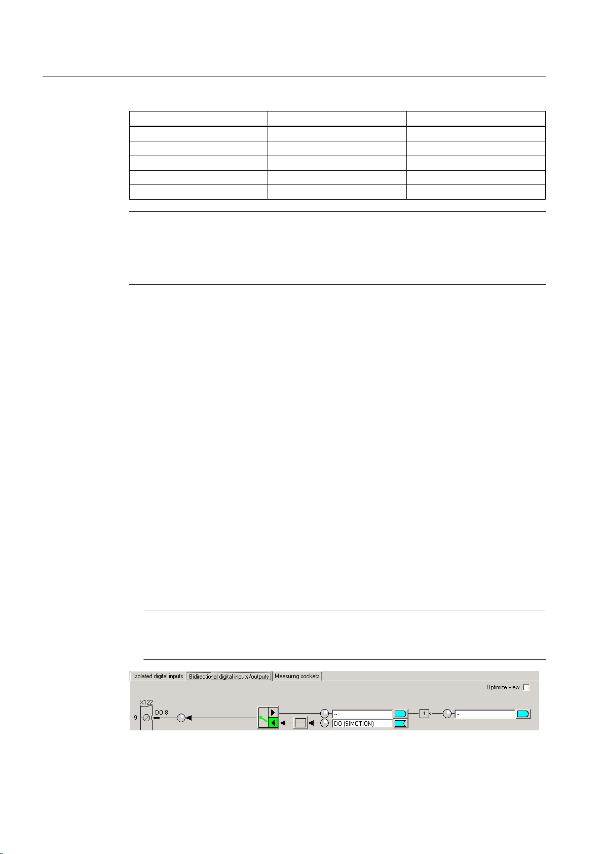
Output Cam TO - Part I
3.3 Configuring the Output Cam technology object
Output D4x5 Output D410 Bit number
X122.11 (DI/DO 11) X121.11 (DI/DO 11) Bit 3
X132.7 (DI/DO 12) - Bit 4
X132.8 (DI/DO 13) - Bit 5
X132.10 (DI/DO 14) - Bit 6
X132.11 (DI/DO 15) - Bit 7
Note
In the case of versions earlier than V4.2, when using 39x telegrams, the onboard D4x5
outputs are to be assigned exclusively to SIMOTION. During a consistency check in
SIMOTION SCOUT, no check is made as to whether the entered HW address actually
belongs to a high-speed digital output (DO).
See also
Insertion of Output Cam (Page
Parameterize Output Cam technology object
37)
(Page 37)
Cam output types (Page 22)
3.3.8 Configuring output cams on SIMOTION D410-2
1. In the project navigator, switch to the Control Unit via SINAMICS_Integrated >
Control_Unit.
2. Double-click Inputs/outputs below the control unit. The window appears on the workspace.
3. Switch to the Bidirectional digital inputs/outputs tab.
4. Click the button to switch between the input and output for the digital inputs/outputs (DO 8
to DO15). In each case, switch the DI/DO to the output you wish to use as the output of
output cam. The designation at the terminal strip switches to DO. Cam outputs must always
be defined as outputs so that they can be used. DO 8 is configured as an output in the
diagram. For the output, select the Output cam (SIMOTION)
setting.
Note
Mixed use
of the SIMOTION D410-2 DI/DO as high-speed (output cam) outputs and inputs
of measuring inputs is possible.
Figure 3-25 Digital inputs/outputs onboard
Output Cams and Measuring Inputs
50 Function Manual, 04/2014
Page 51

Output Cam TO - Part I
3.3 Configuring the Output Cam technology object
5. Click Close.
6. Insert a new output cam or a new cam track or use an existing one.
7.
Parameterize the TO Output Cam / Cam Track
8. Double-click Configuration below the output cam or the cam track in the project navigator.
The Configuration window appears in the working area.
9. For high-speed, hardware-supported output cams, you can achieve an output accuracy
exceeding the servo cycle clock based on the hardware used. Should you wish to configure
a high-speed output cam, select the Activate output checkbox and select the Output cam
output (CAM) radio button.
10.Assignment of an output to an output cam/cam track is supported as of V4.2 either by
symbolic assignment (see Chapter Symbolic Assignment (as of V4.2) in the SIMOTION
Runtime Basic Functions manual) or by entering the hardware address.
11.Click OK to close the window and select Project > Save from the menu.
Output Cams and Measuring Inputs
Function Manual, 04/2014 51
Page 52
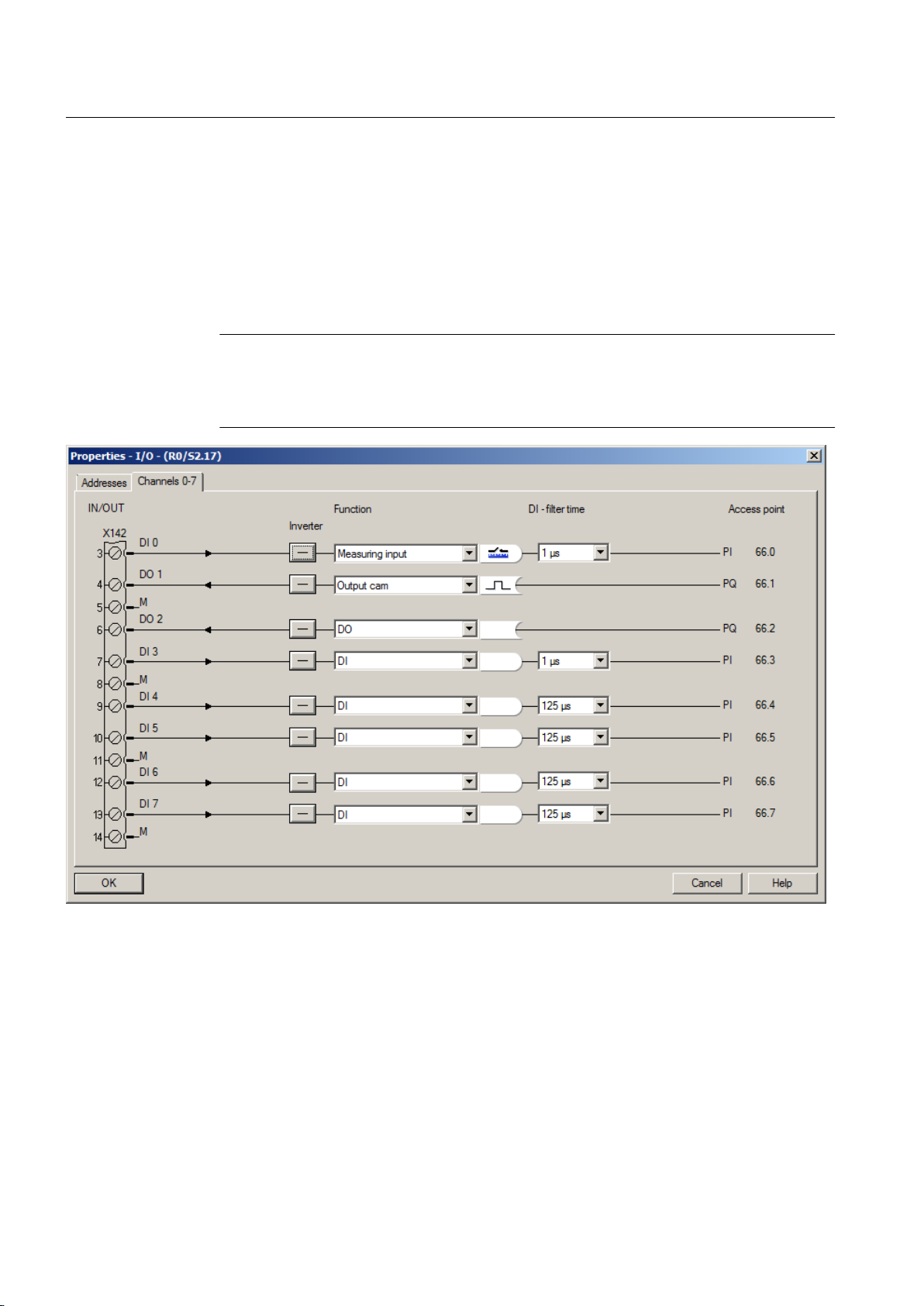
Output Cam TO - Part I
3.3 Configuring the Output Cam technology object
3.3.9 Configuring cams on SIMOTION D4x5-2 onboard
With SIMOTION D4x5-2 the outputs on the interface X142 are used for cam output
1. The Inputs/outputs X142
entry in the project navigator can be used to open the configuration
screen in HW Config.
2. For the selected I/O channel, select Output cam as the function.
Note
If you do not use symbolic assignments (see Chapter Symbolic Assignment (as of V4.2)
in the SIMOTION Runtime Basic Functions manual), you must note the logical address.
(see Figure I/O Properties) This address must be configured at the TO output cam
Figure 3-26 I/O Properties
3. Click OK.
4.
Insert a new output cam or a new cam track or use an existing one.
5. Parameterize the TO Output Cam / Cam Track
6. Double-click Configuration below the output cam or the cam track in the project navigator.
The Configuration window appears in the working area.
7. For high-speed, hardware-supported output cams, you can achieve an output accuracy
exceeding the servo cycle clock based on the hardware used.
If you would like to configure a high-speed output cam, select the Activate output check
box and select the output cam output (CAM) radio button.
Output Cams and Measuring Inputs
52 Function Manual, 04/2014
Page 53

Output Cam TO - Part I
3.3 Configuring the Output Cam technology object
8. Assignment of
an output to an output cam/cam track is supported as of V4.2 using symbolic
assignment or by entering the HW address.
9. Click OK to close the window and select Project > Save from the menu.
3.3.10 Configuring an output cam on a TM15/TM17 High Feature
1. In the project navigator, below the input/output component (TM15/TM17) that you want to
use, double-click the entry Inputs/outputs. The Bidirectional Digital Inputs/Outputs window
is displayed.
2. For the selected I/O channel, select Output cam as the function.
Note
do not use symbolic assignment (see Chapter Symbolic Assignment (as of V4.2) in
If you
the SIMOTION Runtime Basic Functions manual), you must note the offset (e.g. 3.1).
3. Insert a new output cam or a new cam track or use an existing one.
4. Parameterize the TO Output Cam / Cam Track
Double-click Configuration below the output cam or the cam track in the project navigator.
5.
The Configuration window appears in the working area.
6. For high-speed, hardware-supported output cams, you can achieve an output accuracy
exceeding the servo cycle clock based on the hardware used.
If you would like to configure a high-speed output cam, select the Activate output check
box and select the Cam output (CAM) radio button.
7. Assignment of an output to an output cam/cam track is supported as of V4.2 either by
symbolic assignment (see Chapter Symbolic Assignment (as of V4.2) in the SIMOTION
Runtime Basic Functions manual) or by entering the hardware address.
8. Click OK to close the window and select Project > Save from the menu.
Output Cams and Measuring Inputs
Function Manual, 04/2014 53
Page 54
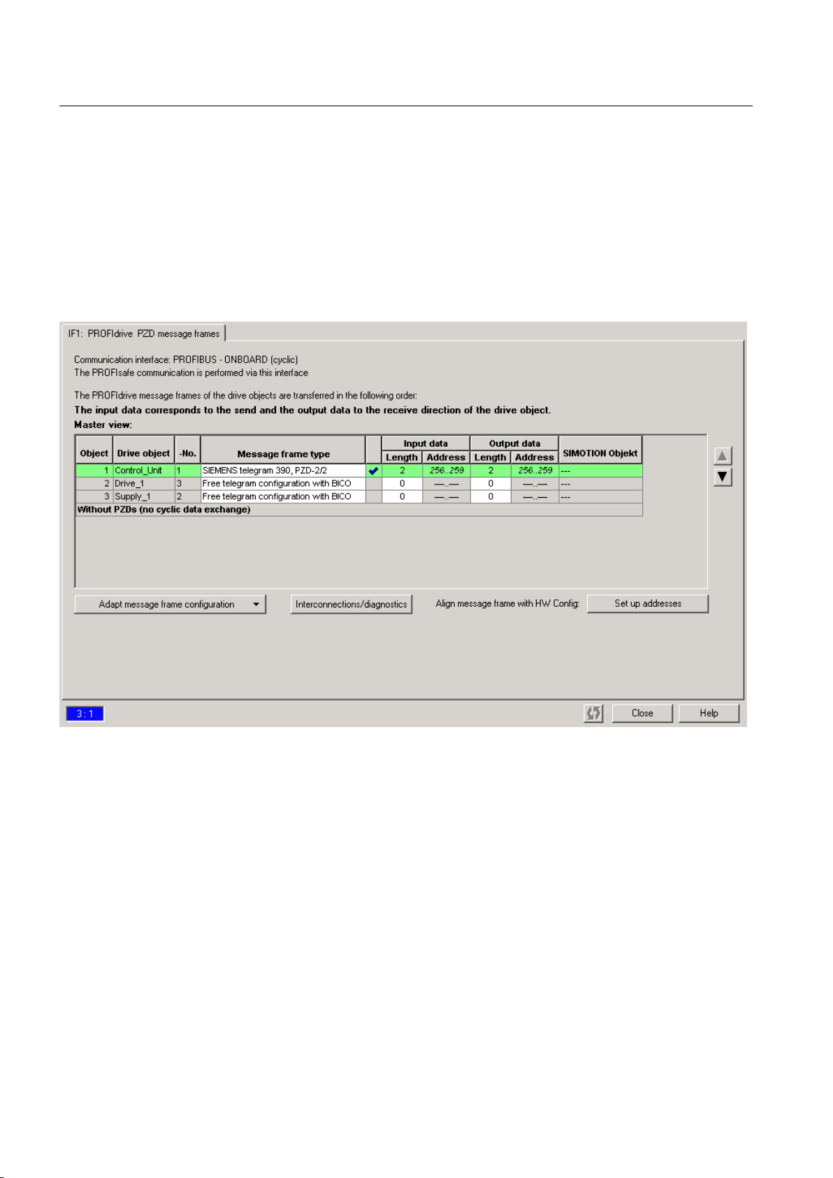
Output Cam TO - Part I
3.3 Configuring the Output Cam technology object
To determine the logical hardware address for TM15/TM17 High Feature outputs (only if
symbolic assignment is not activated)
1. In the project navigator, below the SIMOTION device or the SINAMICS drive unit
- for SIMOTION D, select: SINAMICS_Integrated > Communication > Telegram
configuration
- for
SINAMICS S/G drive unit (position axis only): Communication > Telegram configuration
2. Double-click Telegram configuration and, in the window that opens, select tab IF1:
PROFIdrive PZD telegram. The components are displayed there with the address ranges
(e.g. TM17 output data 304 to 315).
Figure 3-27 Determining the hardware address of the components
3. Before you determine the hardware address, an alignment between HW Config and
SIMOTION SCOUT, with respect to the address, must be performed. If this has not been
performed or you have changed the addresses, click on Set up addresses. If question marks
are entered in the fields instead of I/O addresses, either alignment has not yet taken place,
or the address is not recognized by SIMOTION SCOUT. In this case, you must perform an
alignment.
4. Now calculate the HW address by adding the base output address (first value of the address
range) of the TM to the offset (e.g. 304 + 3 = 307).
5. The bit number is defined by means of the offset. For example, a 3.1 offset of an output
cam on DO 1 results in a bit number of 1.
Output Cams and Measuring Inputs
54 Function Manual, 04/2014
Page 55

3.3.11 Configuring cams on SIMOTION C240
1. Insert a new output cam or a new cam track or use an existing one.
2.
Parameterize the TO Output Cam / Cam Track
3. Double-click Configuration below the output cam or the cam track in the project navigator.
The Configuration window appears in the working area.
4. For high-speed, hardware-supported output cams, you can achieve an output accuracy
exceeding the servo cycle clock based on the hardware used. If you would like to configure
a high-speed output cam, select the Activate output check box and select the High-speed
digital output (DO) radio button
5. Assignment of an output to an output cam/cam track is supported as of V4.2 either by
symbolic assignment (see Chapter Symbolic Assignment (as of V4.2) in the SIMOTION
Runtime Basic Functions manual) or by entering the hardware address. During a
consistency check in SIMOTION SCOUT, no check is made as to whether the entered HW
address actually belongs to a high-speed digital output (DO).
6. Click OK to close the window and select Project > Save from the menu.
Output Cam TO - Part I
3.3 Configuring the Output Cam technology object
3.3.12 HW enable for Output Cam TO
You can make the output of output cams dependent on a hardware-supported enable (only
for TM17 High Feature).
Because hardware enables are mainly used for output cam tracks, this function is described
under Cam Track TO (Page 118).
Output Cams and Measuring Inputs
Function Manual, 04/2014 55
Page 56
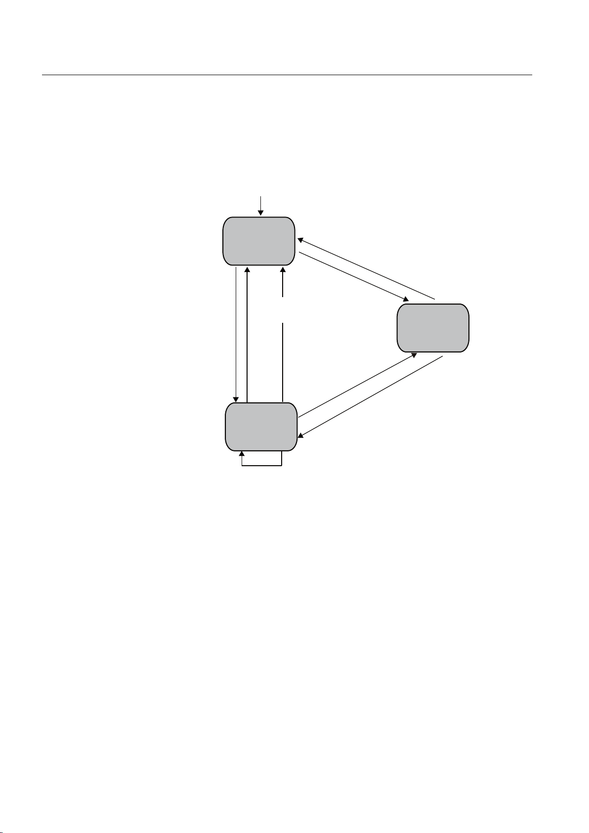
BHQDEOH2XWSXW&DP
BHQDEOH2XWSXW&DP
3RZHURQFRQWUROVWDUWXS
BUHVHW2XWSXW&DP
BUHVHW2XWSXW&DP(UURUZLWKDERUW
(UURU
(UURU
BUHVHW2XWSXW&DP(UURUZLWKRXWDERUW
)DXOW
2XWSXWFDP
FDQEHDFWLYD
WHG
2XWSXW
FDP
DFWLYH
BGLVDEOH2XWSXW&DPDERUW
BVHW2XWSXW&DP6WDWH
Output Cam TO - Part I
3.4 Programming/references of Output Cam TO
3.4 Programming/references of Output Cam TO
3.4.1 Programming
56 Function Manual, 04/2014
Figure 3-28 Programming and execution model for Output Cam technology object
*1 The following commands are effective in the TO states can be activated and active:
● _disableOutputCamSimulation
● _enableOutputCamSimulation
The simulation commands are modal / act in parallel and do not replace any existing
_enableOutputCam commands.
Output Cams and Measuring Inputs
Page 57

3.4.2 Commands
Output Cam TO - Part I
3.4 Programming/references of Output Cam TO
The Output
Cam technology object can be addressed in the user program using the following
commands:
Table 3-8 Output Cam TO system functions
Commands Description Application
_enableOutputCam Activate output cam Output cam analysis is activated. If the
switching condition
fulfilled, the output or state system
variable is set.
_disableOutputCam Deactivate output cam Output cam analysis is deactivated. If
the switching condition for the output
cam is fulfilled, the output or state
system variable is not set. Controlled
output cams are reset immediately.
_enableOutputCamSimulation Activate simulation mode. This function
simulates an output cam by
disconnecting the output.
_disableOutputCamSimulation The output cam is reset from simulation
mode.
_setOutputCamState Deactivate the output cam function and
set the output cam status to the
specified value.
_resetOutputCamError Reset error on output cam TO. E.g. acknowledge configuration errors
_setOutputCamCounter
_resetOutputCam This function sets the output cam to an
_resetOutputCamConfigDataBuffer This function deletes the configuration
Change
initial state.
Modified configuration data is reset on
request.
data collected
activation without activating it.
starting count for a counter cam. Output cam is output on every nth
Pending errors are deleted.
in the buffer since the last
Values are calculated, but not
forwarded to the hardware. Hardware
cams
output
output cam remains internally active,
the status is retained, the output of
output cam is not switched. If an active
output cam is switched to simulation
mode, the output cam status remains
the same, and only the control of the
output is reset or interrupted.
The output of output cam is switched
according to the output cam status and
the signal inversion.
This is used if the output should not be
controlled by the output cam TO.
Example:
glue
nozzle is controlled by the output
A
cam TO (applying glue dots). As a
service function, it should also be
possible to rinse the nozzle while
constantly controlling it. This is achieved
via _setOutputCamState.
after entering correct values.
switching operation.
Create initial state of output cam TO.
Changing configuration data in the RUN
state discards the accumulated
modifications.
for the output cam is
act as software cams. The
Output Cams and Measuring Inputs
Function Manual, 04/2014 57
Page 58

Output Cam TO - Part I
3.4 Programming/references of Output Cam TO
Commands Description Application
_getStateOfOutputCamCommand
(V3.2 and higher)
_bufferOutputCamCommandId
(V3.2 and higher)
_removeBufferedOutputCamCom
mandId
(V3.2 and higher)
This function returns the execution state
of a command.
This function enables commandId and
the associated command status to be
saved beyond the execution period of
the command.
The commandId parameter is used to
define the command for which the
respective status is to be saved. The
maximum number of saveable
command status is specified in the
decodingConfig.numberOfMaxBuffered
CommandId
This function ends saving of
commandId and the associated
command status beyond the execution
period of the command.
configuration data element.
Check whether the output cam
switching has already taken place, i.e.
whether the command ID is still
available or has already been deleted.
Subsequent check of how command
was terminated, e.g. error-free or
number of error that occurred.
Explicit deletion of previously saved
command IDs.
For further information on the system functions, please refer to the
Reference Lists
3.4.3 Process Alarms
You can predefine local alarm responses via SIMOTION SCOUT.
Note
For more information, refer to the
functional description.
How to configure the alarm response:
1. Double-click Execution system in the project navigator below the SIMOTION device. The
execution system opens.
2.
In the execution level tree, select SystemInterruptTasks > TechnologicalFaultTask.
3. Then click the Alarm Response button in the displayed window. The Alarm Response
window appears. You can configure the alarm response for every TO here.
A system variable error indicates that a technology alarm has been generated. The response
to the alarm is displayed in the errorReaction variable.
SIMOTION TP CAM
.
Motion Control Technology Objects Basic Functions
Output Cams and Measuring Inputs
58 Function Manual, 04/2014
Page 59
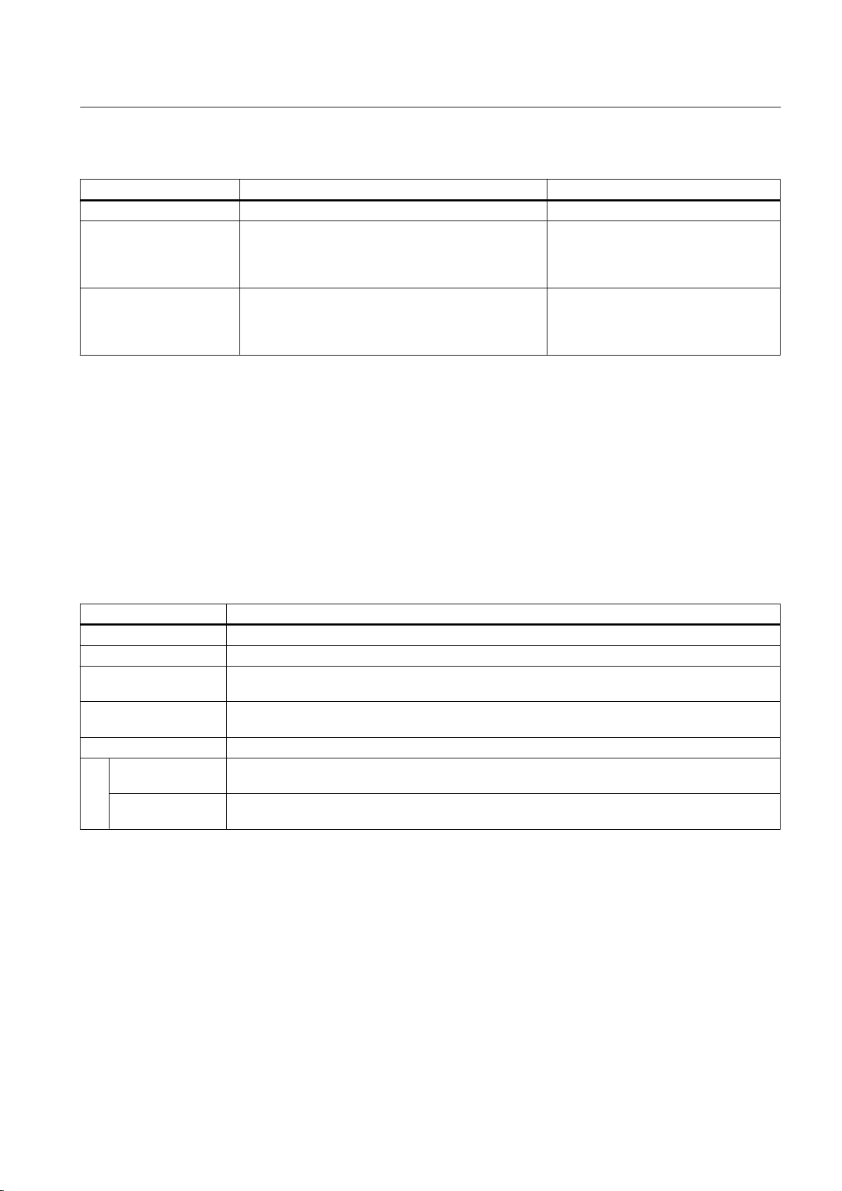
3.4 Programming/references of Output Cam TO
Table 3-9 Possible alarm responses
Alarm Response Description Application
NONE No response -
DECODE_STOP Command processing is aborted, the output cam
function remains active. Execution on the technology
object can continue after _resetOutputCam or
_resetOutputCamError.
OUTPUTCAM_DISABLE Command processing is aborted, current output cam
function is aborted. Execution on the technology
object can continue after _resetOutputCam or
_resetOutputCamError.
The Output Cam TO can only be
reactivated after the error has been
acknowledged.
The Output Cam TO can only be
reactivated after the error has been
acknowledged.
3.4.4 Output Cam TO menus
3.4.4.1 Output cam menu
Grayed-out menu functions cannot be selected. The menu is only active if an output cam
window is active in the working area.
Output Cam TO - Part I
You can select the following functions:
Table 3-10 Output cam TO menu
Function Significance/Note
Close Select Close to
Characteristics Select Properties to display the properties of the output cam highlighted in the project navigator.
Configuration Select Configuration to determine the configuration data (for example output cam type) of the
output cam.
Default Select Default to define the default settings of the system variables (e.g. effective direction) for
the output cam.
Expert
Expert list Select Expert
system variables can be displayed and changed in this list.
Configure units Select Configure units to open the Configure units of the object window in the working area. You
can configure the units used for the selected object here.
close the configuration window for the output cam that is open in the working area.
list
to open the expert list for the highlighted output cam. The configuration data and
3.4.4.2 Output cam context menu
Grayed-out functions in the context menu cannot be selected.
Output Cams and Measuring Inputs
Function Manual, 04/2014 59
Page 60

Output Cam TO - Part I
3.4 Programming/references of Output Cam TO
You can select the following functions:
Table 3-11 Output cam context menu
Function Significance/Note
Open configuration
Expert list Select Expert list to open the expert list for the highlighted output cam. The configuration data and
Cut Select Cut to remove the selected object and save it to the clipboard.
Copy Select Copy to copy the selected object. It is stored in the clipboard.
Paste Select Paste to insert the output cam stored in the clipboard.
Delete Select Delete to delete the highlighted output cam. The entire data of the output cam is deleted
Rename Use Rename to rename the object selected in the project navigator. Note that with name changes,
Expert
Insert script
folder
Import object Import object imports the data of a SIMOTION object from another project which was previously
Save project
and export
object
Print Select Print to
Print preview Select Print preview to open the preview of the output cam data to be printed.
Default Select Default to define the default setting of the system variables (e.g. effective direction) of the
Properties Select Properties to display the properties of the output cam highlighted in the project navigator.
Select Open configuration to display the window for configuring the output cam in the working area.
Enter the configuration data (for example, output cam type) for the output cam in this window.
system variables can be displayed and changed in this list.
permanently.
name references to this object are not adapted.
Insert script folder enables you to insert a folder below the TO. You can create scripts in this folder
in order to, for example, automate the configuration.
created with a selective XML export. You cannot import the entire project, only the data of the
SIMOTION object.
Save project and export object
export can then be reimported into other projects. Only the data of the selected object, not the entire
project, is exported.
print the configuration of the output cam. All system variables and configuration data
with the associated values are printed.
output cam.
exports
selected data of the selected object in XML format. This data
Output Cams and Measuring Inputs
60 Function Manual, 04/2014
Page 61
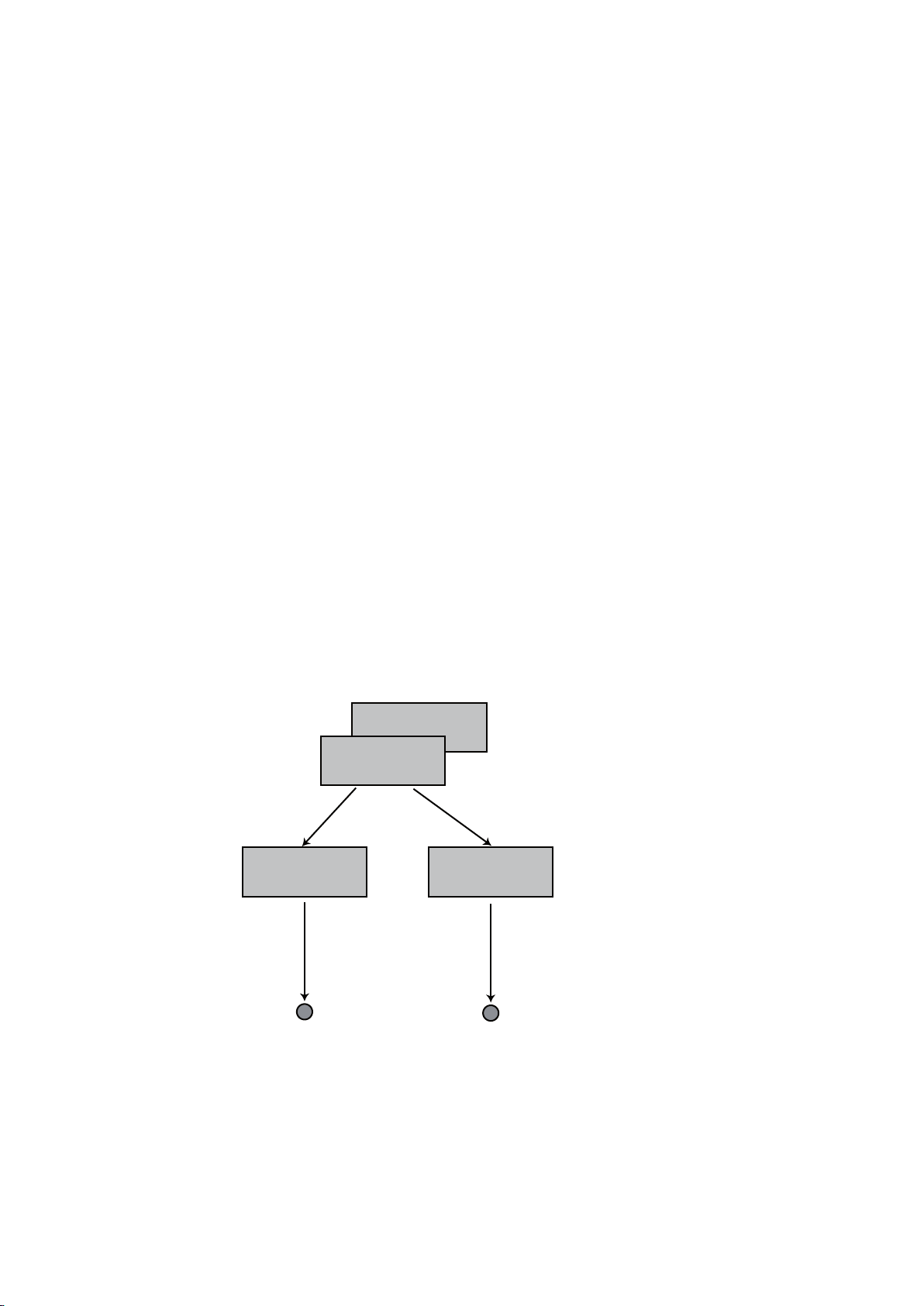
Cam Track TO - Part II
([WHUQDOHQFRGHU
$[LV
&DP7UDFN72
&DP7UDFN72
2XWSXW
2XWSXW
4.1 Overview of TO Cam Track
4.1.1 General information about Cam Track TO
Cam tracks allow several output cams to be output as a track on one output.
Cam Track technology object
The
● Generates position-dependent switching signals
● Can be assigned to positioning axes, synchronous axes or external encoders
● The axes can be real or virtual.
Different switching signals distinguish different types of output cam on the cam track:
● Software cam
Switching signals are used internally in the user program by evaluating the relevant state
system variable.
● Hardware cams
Switching signals are output externally on I/O by assigning a digital output to the cam track
TO. For example, digital output modules from the ET 200 I/O system can be used for cam
track output.
4
Output Cams and Measuring Inputs
Function Manual, 04/2014 61
A range of output cam types with different switching behaviors are available on a cam track:
Figure 4-1 Interconnection options for the cam track TO
Page 62

Cam Track TO - Part II
4.1 Overview of TO Cam Track
● Position-based cam
The switching
● Time-based cam
The switching signal is supplied for a specified time period after the switch-on position is
reached.
● Time-based cam with maximum ON length
A maximum ON length can be defined for time-based cams. This means that the time-based
cam is deactivated once it has covered the maximum length, even though the
parameterized time has not yet expired.
● High-speed/accurate output cam (hardware-based output cam)
Although output cams are usually output in IPO cycles or the servo cycles, high-speed
output cams achieve output accuracy that is better than the servo cycle clock because the
switching edges are output within servo cycles.
4.1.2 Functionality
Cam track functionality
● Cam tracks allow up to 32 output cams to be configured within one TO and allow, for
example, the switching point for all output cams to be shifted collectively.
signal is supplied between the switch-on position and the switch-off position.
● The switching of several output cams is dependent on the same setpoint/actual value, and
they are output on one output.
● Any number of cam tracks can be used per axis. The only restriction placed on this number
is the system performance.
● The cam track can be calculated in servo cycles, IPO cycles, or IPO_2 cycles.
● All output cams on one track are of the same type (position or time-based cams).
● Cam tracks can be activated once or cyclically.
● Various modes are available for activating and deactivating cam tracks, e.g. active
immediately, next track cycle, etc.
● Cam track output can be inverted.
● The status of each single output cam (controlled/not controlled) can be read over one array
of byte.
● Single output cams on a cam track can also be defined as valid/invalid.
● In connection with the TM17 High Feature terminal module, the cam track output can be
controlled via a high-speed hardware enabling signal.
Reference to axis
The reference values of the cam track depend on the axis type or the external encoder:
Output Cams and Measuring Inputs
62 Function Manual, 04/2014
Page 63

Table 4-1 Reference to the actual or set position
Cam Track TO - Part II
4.1 Overview of TO Cam Track
Technology object Reference to actual position
possible
Real drive axis - Real position axis X X
Real synchronized axis X X
Virtual axes - X
External encoder X -
Reference to set position
possible
Possible configuration of the cam tracks with actual value reference:
● Reference to
the actual value on the encoder without considering Ti. Reference to the actual
position in the controller before the position filter.
● Reference to the actual value after the position filter. Reference to the actual position in the
controller after the position filter.
● Reference to the actual value on the encoder. Ti is taken into account. Reference to the
actual value on the encoder module / drive. The transmission time Ti from the encoder
module / drive to the controller is taken into account by the system.
Possible configuration of the cam tracks with setpoint reference:
● Reference to the setpoint after the fine interpolator. The cam switch points are calculated
as if the setpoints will already have been reached at the end of this IPO cycle, e.g. if a
setpoint is calculated for the IPO cycle clock with the virtual axis and also displayed at the
end of the cycle. Reference is made directly to the setpoint applicable at the end of the
cycle.
● Reference to the setpoint after the fine interpolator. The cam switch points are calculated
as if the setpoint calculated in the interpolator will be output completely in the following
cycle and the calculated position setpoint will therefore be reached at the end of the
following cycle.
● Reference to the setpoint on the drive. Calculation of the cam switch points according to
the setpoint output with the current settings on the drive.
In this case, the cam track functionality can be applied to axes or external encoders with or
without modulo properties.
The cam track is also effective for axes that have not been homed.
The cam track is defined independently of the axis. The cam track is mapped on the axis via
an axis reference position, once the track is activated. This enables cam tracks to be operated
in a particularly flexible way (e.g. relative output of a cam track on the basis of a measured
edge on the measuring input, cam track offset, etc.).
Output on one output
The cam track TO is assigned to one output only during configuration. Output can be achieved
via:
● Onboard I/O
● Drive I/O (for example TB30, TM31, TM1x)
● SIMOTION C centralized I/O
● Distributed I/O; PROFIBUS DP I/O (e.g. ET 200M)
Output Cams and Measuring Inputs
Function Manual, 04/2014 63
Page 64

Cam Track TO - Part II
4.1 Overview of TO Cam Track
However, the output must not be in the process image.
The switching accuracy is dependent on the following:
● Output accuracy of the I/O
●
How the cam track is allocated in the task system
● How constant delay times are compensated
4.1.3 Comparison of Output Cam TO and Cam Track TO
Depending on the application, it is practical to use either the Cam Track TO or one or more
Output Cam TOs. The table below should help you to decide which TO should be used in
which case.
Table 4-2 Comparison of Output Cam TO and Cam Track TO
Features Output Cam TO Cam Track TO
Availability ● As of Version 1.0 ● As of Version V3.2
Supported output cams ● Position-based cam
● Time-based output cam
Unidirectional output cam
●
● Counter cam
● Exact time setting of an output,
exact time output cams (as of V4.1)
Several output cams on one output ● Via logical operation (AND/OR) ● Maximum 32 output cams of the
Different types of output cam on one
output
Output cam definition ● Related to axis
Hysteresis ● Available ● Available
Effective direction ● Available ● Not available
Derivative-action times ● Separate for power ON/power OFF ● Separate for power ON/power OFF
Deactivation time for time-based cam ● As of Version V3.2 ● As of Version V3.2
Activation/deactivation types ● Active immediately ● Start and stop mode
Types of output ● Cyclic ● Cyclic
Output cam status ●
Output cam enable ● Via_enableOutputCam ● via_enableCamTrack
Via AND/OR ● Not available
●
Via system variables
●
System variable ● Status of single output cams over
● Position-based cam
● Time-based output cam
● Time-based cam with maximum ON
length
same type in one track
● No cam track logical operations
(AND/OR)
●
Related to cam track (cam track can
be mapped as required on axis)
● Via system-variables array
parameterizable
Once
●
one array of byte
Validity of single output cams
●
configurable via system variables
Output Cams and Measuring Inputs
64 Function Manual, 04/2014
Page 65

Cam Track TO - Part II
4.1 Overview of TO Cam Track
Features Output Cam TO Cam Track TO
on
Performance ● Depends
cams
MCC command available ● Available ● Available (V4.0 and higher)
number of single output
● When 5 or more output cams are
used in one output cam track instead
of 5 single output cams, the output
cam track performs better. This
performance advantage amounts to
at least a factor of 2 for 32 single
output cams.
Output Cams and Measuring Inputs
Function Manual, 04/2014 65
Page 66

Cam Track TO - Part II
4.2 TO Cam Track basics
4.2 TO Cam Track basics
4.2.1 Cam track features
A cam track has parameters that are valid for the track as a whole, and parameters that can
be configured for each single output cam on a track.
Track data
Track data is valid for all output cams on a track and is, therefore, configured for the cam track
as a whole.
● Output cam type
Position-based, time-based, etc.
● Cam track start
Always defined from "0"
● Track length
Cam track start to cam track end
● Hysteresis
Even if the switching conditions change, the output cam does not change its switching state
in this defined range around the switching position.
● Actuation times
Actuation times can be specified to compensate for the switching times of digital outputs
and connected switching elements.
● Axis reference position
Cam tracks are defined independently of the axis. The axis reference position is used to
define how the cam track is mapped on the axis, or from which axis position the cam track
should be output.
● Cyclic or non-cyclic activation mode
If the cam track is output non-cyclically, it will have to be reactivated after execution.
● Start mode and stop mode
Start mode or stop mode can be used, for example, to define whether a cam track will be
output immediately or not until the next track cycle.
Output cam data
Output cam data can be configured separately for each single output cam on a cam track.
● Output cam parameters:
Depending on output cam type, start position, end position, ON duration, maximum ON
length.
● Validity of single output cam
Single output cams on a defined cam track can be parameterized as "invalid." This output
cam is completely suppressed and is not output. It also has no status indication.
Output Cams and Measuring Inputs
66 Function Manual, 04/2014
Page 67
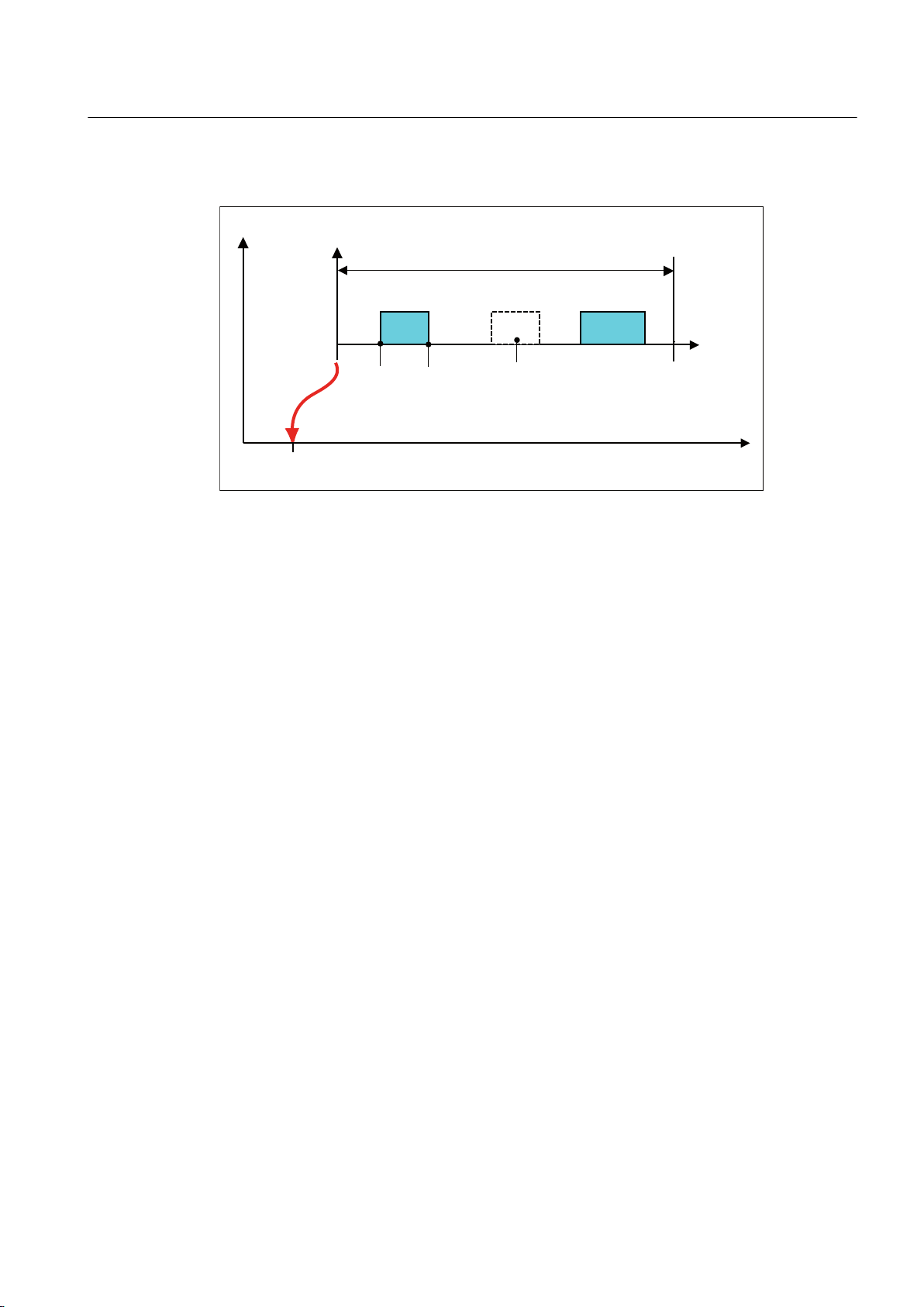
Example of a cam track definition
2&2&
2&
7UDFNOHQJWK
&DPWUDFN
VWDUW
&DPWUDFN
(QG
6WDUWLQJ
SRVLWLRQ
(QG
SRVLWLRQ
$[LVSRVLWLRQ
2XWSXWFDP
FDP7\SH
RXWSXWVXSSUHVVHG
LQYDOLG
$[LVUHIHUHQFHSRVLWLRQ
Figure 4-2 Definition of a cam track with 3 output cams
Cam Track TO - Part II
4.2 TO Cam Track basics
4.2.2 Output cam types of the single output cams on a track
The following chapter provides an overview of the output cam types within a cam track. All
output cams on a cam track are always of the same output cam type.
Software cam (Page 67
Hardware cam (Page 67)
Position-based cam (Page 68)
Time-based cam (Page 69)
Time-based cam with maximum ON length (Page 70)
High-speed/accurate output cam
4.2.2.1 Software cam
Switching signals are used internally in the user program by evaluating the relevant state
system variable.
4.2.2.2 Hardware cam
)
Description
Output Cams and Measuring Inputs
Function Manual, 04/2014 67
Switching signals are output externally on I/O devices by assigning a digital output to the Cam
Track TO.
The following can be used as digital outputs:
Page 68
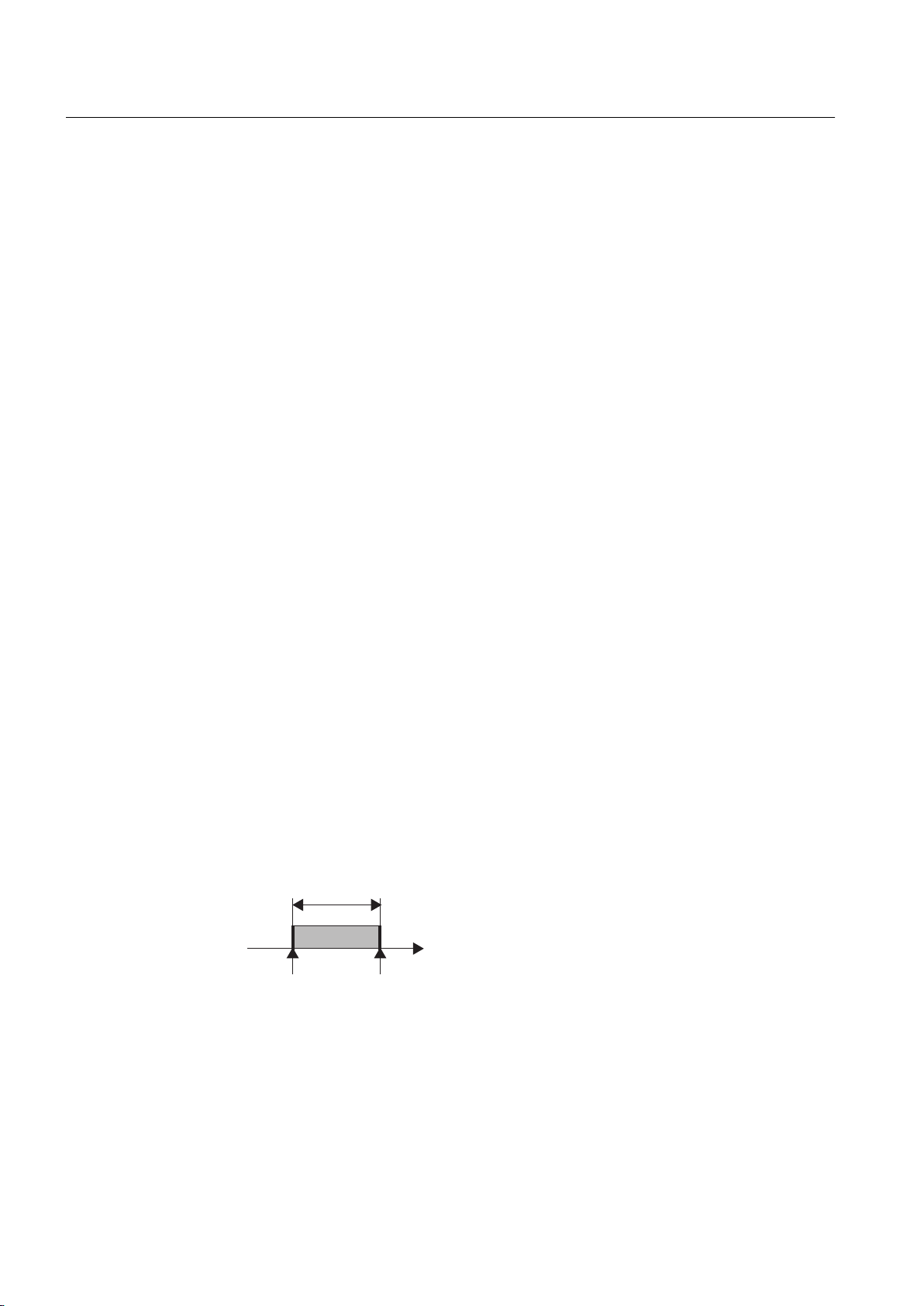
&DPDFWLYDWLRQUDQJH
6WDUWLQJSRVLWLRQ(QGSRVLWLRQ
Cam Track TO - Part II
4.2 TO Cam Track basics
● Onboard outputs (SIMOTION C, D, ...)
● Centralized I/O (SIMOTION C)
●
Distributed I/Os via PROFIBUS DP (e.g. ET 200M) and PROFINET IO (e.g. ET 200S)
● Drive I/O (for example, TM15 and TM17 High Feature terminal modules)
Hardware for cam track
Cam output on cam output (I/O channel is configured as CAM)
● SIMOTION D410-2
● SIMOTION D4x5-2
● TM15, TM17 High Feature
Cam output on high-speed output with direct access (I/O channel is configured as DO)
● SIMOTION D4xx / D4x5-1
● SIMOTION C240, C240 PN
Cam output on standard output (I/O channel is configured as DO)
● SIMOTION C/D/CX onboard I/O
● SINAMICS onboard I/O
● TM15, TM15 DI/DO, TM17 High Feature, TM31, TM41, TB30
● Standard DO (SIMATIC ET200, ...)
4.2.2.3 Position-based cam
Switching behavior
Position-based cams on a cam track switch independently of the direction of motion, i.e. they
always have a positive and negative effective direction.
Figure 4-3 Position-controlled output cam with a starting position less than the end position
Limits imposed by starting and end positions
The cam is activated:
68 Function Manual, 04/2014
Output Cams and Measuring Inputs
Page 69
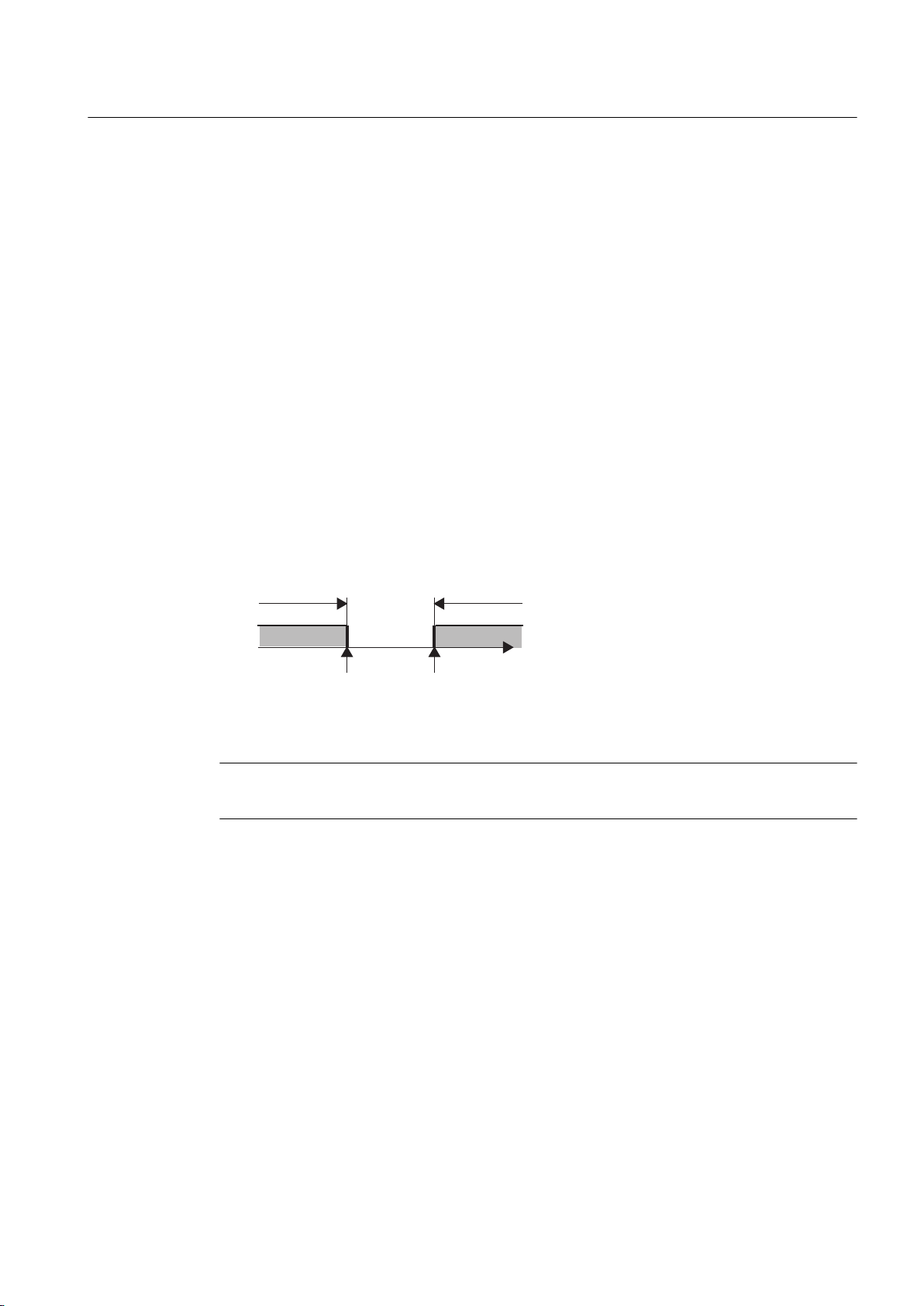
&DPDFWLYDWLRQUDQJH
6WDUWLQJSRVLWLRQ
(QGSRVLWLRQ
&DPDFWLYDWLRQUDQJH
Cam Track TO - Part II
4.2 TO Cam Track basics
● if the axis position is within the activation range
● if the axis position value is shifted into the activation range of the output cam
The
position value of the interconnected object can change abruptly, for example, when it
is homed or when its coordinate system is shifted with the _redefinePosition command.
The output cam is switched off:
● if the axis position is outside the starting or end position
● if the position value is shifted outside the activation range
● via commands that deactivate the output cam, e.g. _disableCamTrack,
_setCamTrackState, _resetCamTrack
Cam activation range
The activation range of the output cam is defined from the start position to the end position in
a positive direction of motion, i.e. in the range between the starting position and end position.
If the end position is greater than the starting position, the activation range is defined by the
starting and end positions (see figure above).
The activation range is outside the range between the end and starting positions if the end
position is less than the starting position (see figure below).
4.2.2.4
Figure 4-4 Position-controlled cam with an end position less than the starting position
Note
This definition of the activation range is possible for all modulo and non-modulo axes.
ON duration
The ON duration of the output cam depends on the velocity at which the axis traverses the
output cam length.
Time-based output cam
Switching behavior
Time-based cams on a cam track switch independently of the direction of motion, i.e. they
always have a positive and negative effective direction.
Output Cams and Measuring Inputs
Function Manual, 04/2014 69
Page 70
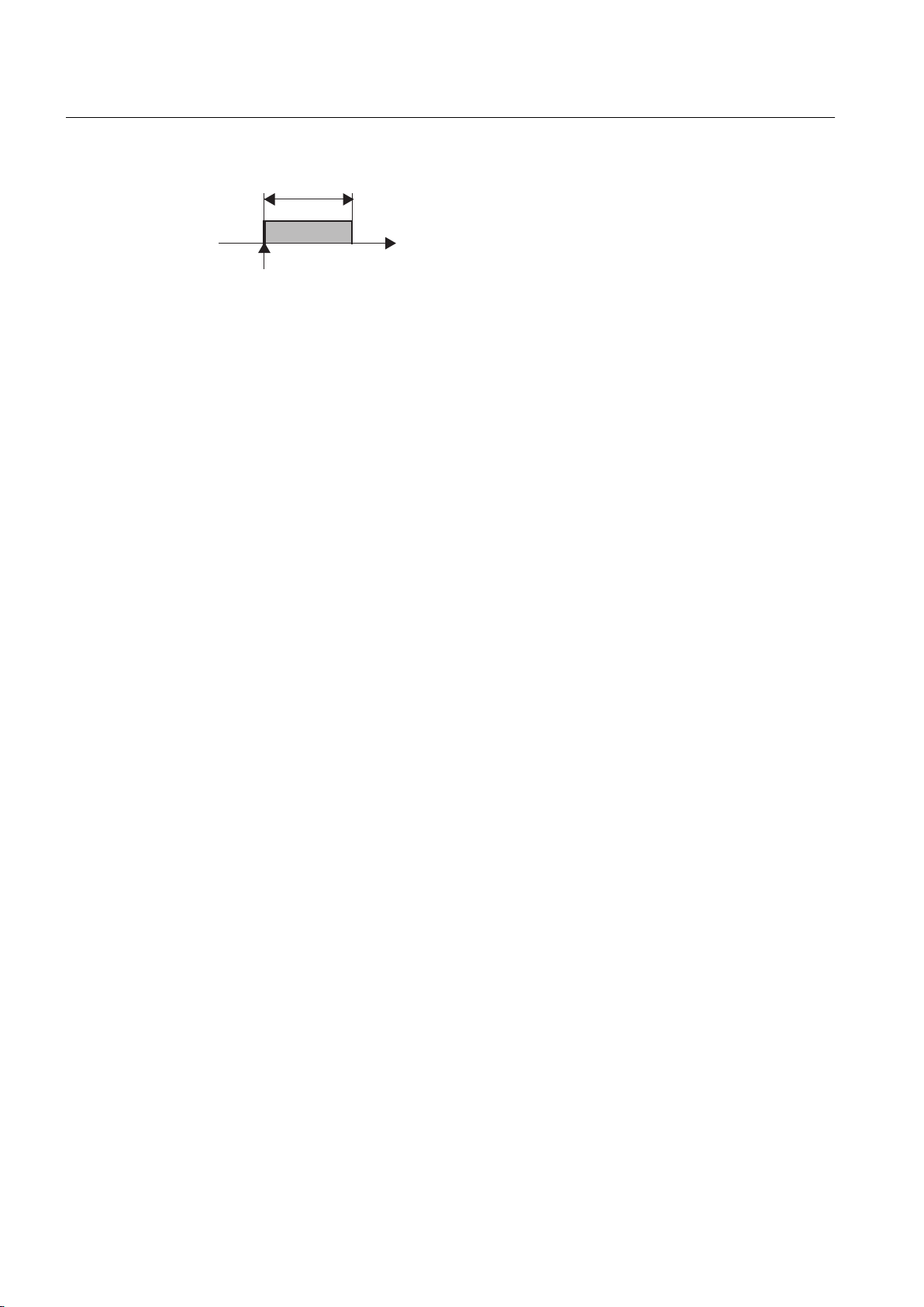
21GXUDWLRQ
6WDUWLQJSRVLWLRQ
Cam Track TO - Part II
4.2 TO Cam Track basics
Figure 4-5 Time-controlled output cam
Limits imposed by starting position and ON duration
The output cam is switched on:
● At the starting position.
If the starting position is overrun again during the ON duration, the time-based cam is not
switched on again. It is not possible to retrigger a time-based cam.
The output cam is switched off:
● When the assigned time period expires
● When commands are issued that deactivate the output cam, e.g. _disableOutputCam,
_setOutputCamState and _resetOutputCam
Output cam length
The output cam length is dependent on the velocity at which the assigned axis traverses during
ON duration of the output cam.
4.2.2.5 Time-based cam with maximum ON length
Additional limits imposed by maximum ON length
A maximum ON length can also be defined for time-based cams on cam tracks. This means
that the time-based cam is deactivated once it has covered the maximum length, even though
the parameterized time has not yet expired.
This is the case if, for example, glue dots should be applied to a workpiece and the amount of
glue should be independent (constant time -> time-based cam) of the throughput rate.
To avoid the time-based cam still being controlled after the end of the workpiece at high sweep
rates, the ON duration can be limited by a maximum ON length (related to the start position of
the output cam). This prevents a glue dot being placed adjacent to the workpiece.
The maximum ON length is effective in both traversing directions of the axis, and the cam
track's switch-on position is the reference position.
Parameters of a time-based cam with maximum ON length
Every time-based cam on a track has three parameters
70 Function Manual, 04/2014
Output Cams and Measuring Inputs
Page 71
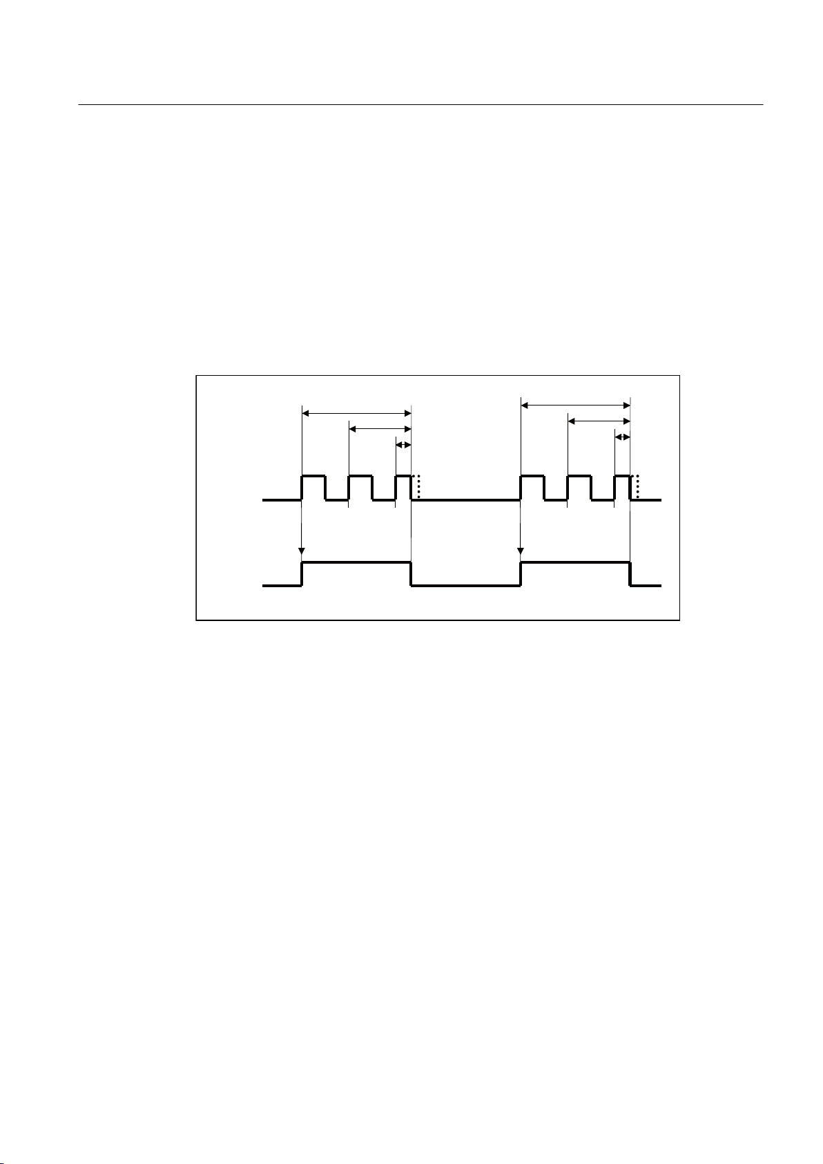
62&
62&
62&
62&
62&
62&
W
W
W
W
W
W
(2&PD[
(2&PD[
(2&PD[
(2&PD[
(2&PD[
(2&PD[
*OXHDSSOLFDWLRQ
UDQJH
3RVLWLRQWLPHEDVHG
FDP
ZLWKPD[LPXP21
OHQJWK
Cam Track TO - Part II
4.2 TO Cam Track basics
● Start of output cam (SOC)
● ON time (t)
●
Maximum ON length (Lmax)
This always relates to the dynamically adjusted start of output cam SOC, i.e. the assigned
activation time is taken into account. The output cam is then traversed over the maximum
ON length, without taking into account the deactivation time (see the Actuation times
(activation time/deactivation time section).
Example of a cam track which controls glue application
In the following example, a cam track with three output cams is used to control the application
of glue onto a workpiece. No glue may be applied outside of the predefined areas.
4.2.2.6 Cam output types
Output Cams and Measuring Inputs
Function Manual, 04/2014 71
Figure 4-6 Control of
glue application via a cam track, based on a time-based cam with maximum ON
length
● The start of output cam (here, SOC1 and SOC4) is used to exactly define the start of glue
application.
● The ON time (t) is used to ensure that the same amount of glue is applied, independent of
the axis speed.
● The maximum ON length Lmax is used to ensure that no glue is applied outside of the
defined area. In the example, the output cam ON durations t3 and t6 are limited by the
maximum ON length.
The cam calculations are performed in the processing cycle clock (IPO or IPO_2 cycle clock
or in the servo cycle clock). For the possible setting of Servo_fast or IPO_fast, see Chapter
Second servo cycle clock (Servo_fast) in the SIMOTION Runtime Basic Functions manual.
The temporal resolution of the cam output depends on the hardware used and the setting in
the configuration. In standard applications, the setting is undertaken using screen forms. The
configuration data can also be set via the expert list.
The possible setting options for cam output are described below:
Page 72
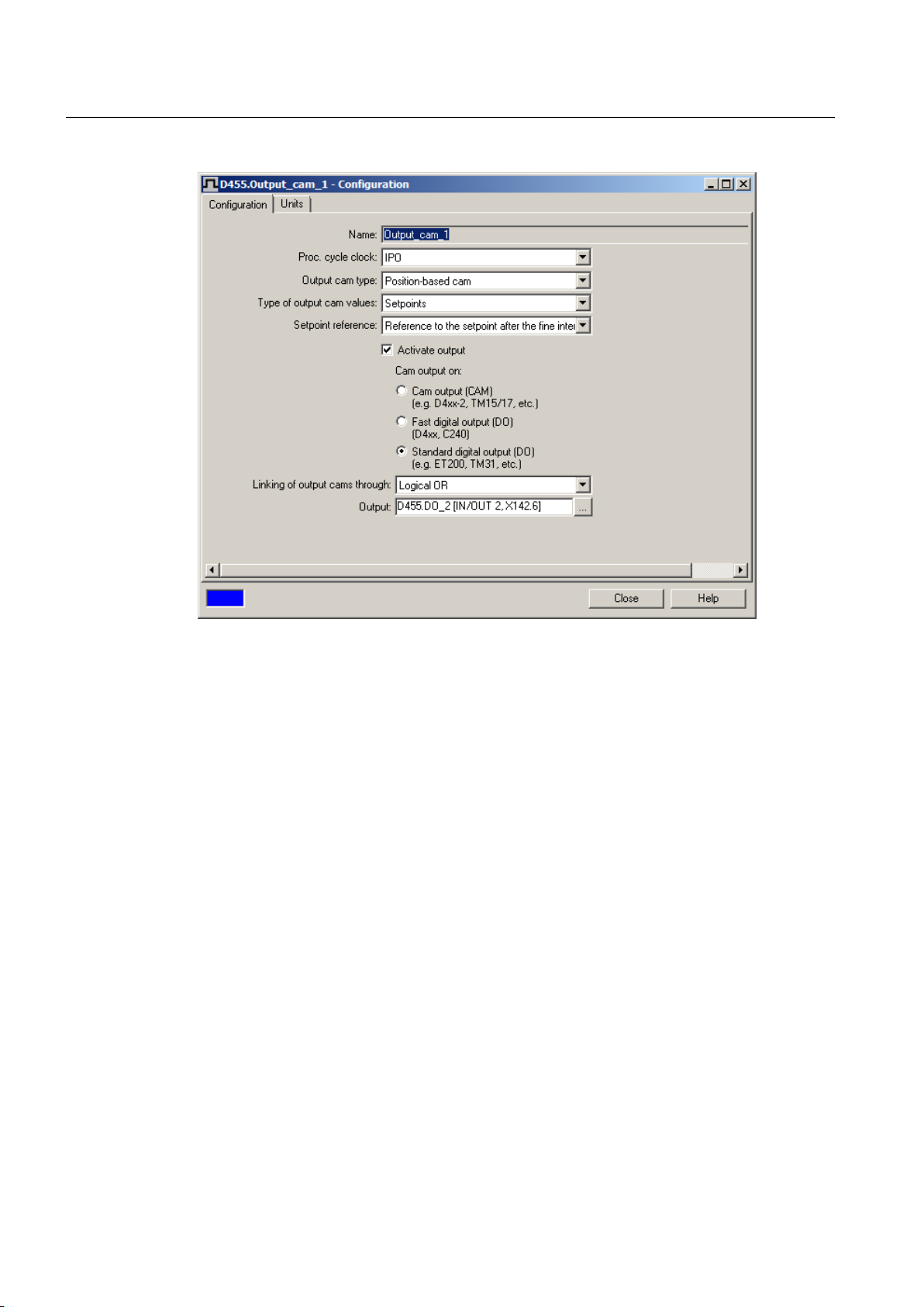
Cam Track TO - Part II
4.2 TO Cam Track basics
Figure 4-7 Output cam configuration using the example of a position-based cam
Output Cams and Measuring Inputs
72 Function Manual, 04/2014
Page 73
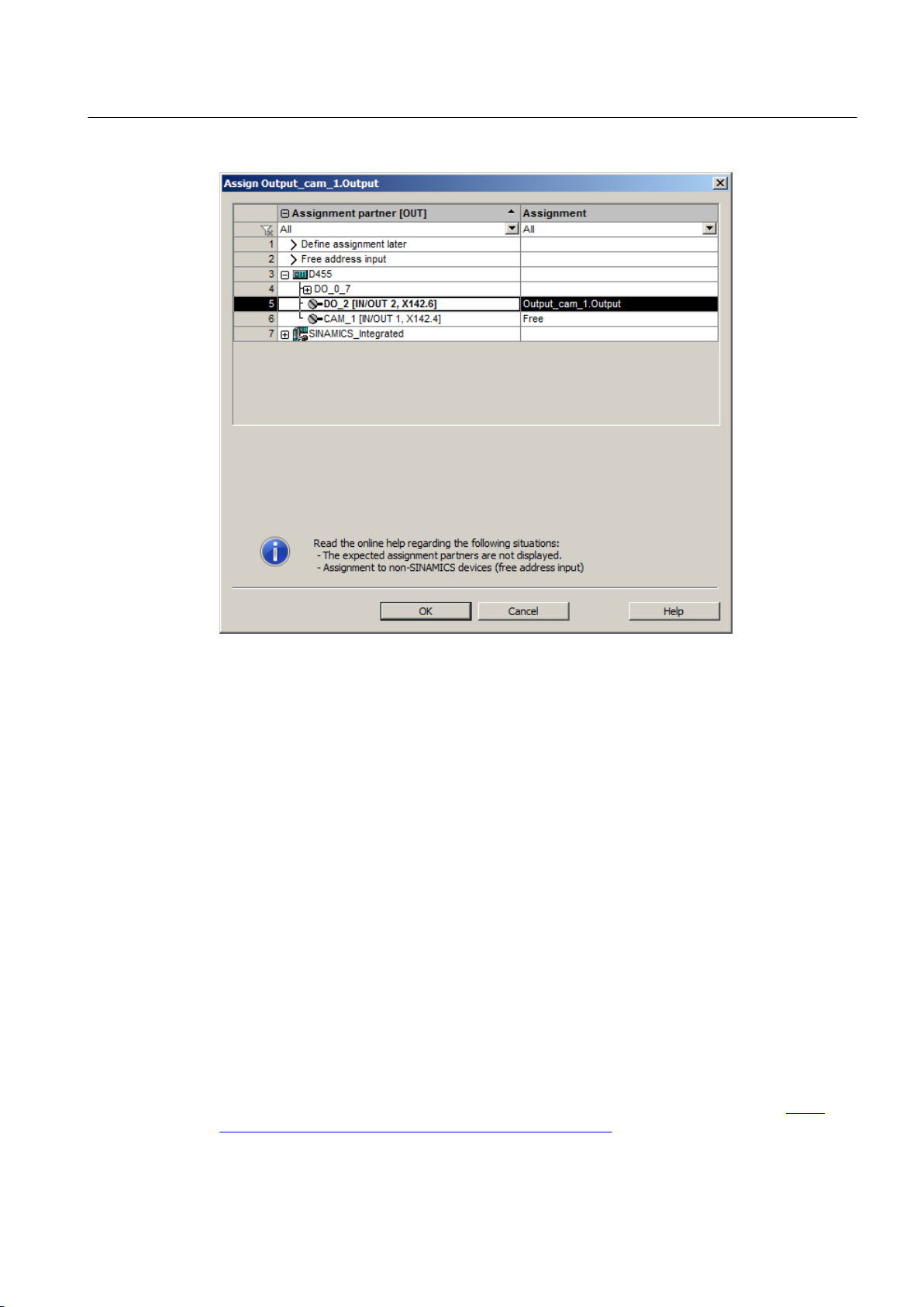
Cam Track TO - Part II
4.2 TO Cam Track basics
Cam output (CAM)
Figure 4-8 Assignment dialog
Symbolic assignment is activated by default in projects as of V4.2 (Project > Use symbolic
assignment)
The cam output is performed on the basis of an internal time stamp. The temporal resolution
of the cam output depends on the hardware used. In the case of D4x5-2 and the TM17 High
Feature, the resolution is 1 µs.
Hardware supported
● SIMOTION D410-2
● SIMOTION D4x5-2 (X142)
● TM15, TM17 High Feature
The I/O channel must be configured as CAM.
SIMOTION D410-2
The digital inputs/outputs are used for the cam output in the D410-2. The digital inputs/outputs
can be used as the cam output (CAM) from the user program.
As of the editorial deadline of this documentation, the output cam resolution for D410-2 was
not yet certain. The information can be found at the following website Internet link (http://
support.automation.siemens.com/WW/view/en/27585482).
Output Cams and Measuring Inputs
Function Manual, 04/2014 73
Page 74

Cam Track TO - Part II
4.2 TO Cam Track basics
SIMOTION D4x5-2 onboard outputs (interface X142)
The D4x5-2 onboard outputs can be used as cam output (CAM) from the user program. The
D4x5-2 onboard outputs are permanently assigned to SIMOTION. The X142 I/Os are
configured using HW Config.
The X142 configuration screen form can be accessed directly from the project navigator in
SIMOTION SCOUT.
With SIMOTION D4x5-2, output cams are output at the X142 interface with a resolution of 1
μs.
TM15 / TM17 High Feature Terminal Modules
The TM15
within the SIMOTION Motion Control system. The Terminal Modules are connected directly to
SIMOTION D or CX32/CX32-2 via DRIVE-CLiQ for this purpose.
Alternatively, TM15 and TM17 High Feature can be connected to a SINAMICS S120 CU320/
CU320-2/CU310/CU310-2 Control Unit with higher-level SIMOTION C, P or D.
Output cams on the TM15 operate with DRIVE-CLiQ cycle-clock resolution (typically 125 µs).
Output cams on the TM17 High Feature have a resolution of 1 µs.
and TM17 High Feature Terminal Modules can be used to set up cam outputs (CAM)
If current controller cycle clocks other than 125 μs are used, the parameter calculations of the
drive must be taken over into the PG and the Fast IO configuration must be recreated when
using cam outputs on TM15/TM17 High Feature. (For more information, see chapter Current
controller cycle clocks <> 125 μs / use of output cams and measuring inputs in the TM15 /
TM17 High Feature Terminal Modules Commissioning Manual.)
High-speed digital output (DO)
The cam output is performed via onboard outputs of the SIMOTION CPU. The output is via a
hardware timer and the cam output is achieved with a resolution with respect to time < servo
cycle clock.
The time that it takes for the axis to reach the output cam switching position with reference to
the processing cycle is calculated by linear extrapolation. Calculated from the beginning of the
1st position control cycle, the output cam function is triggered by a hardware time when this
time is reached.
Hardware supported
The onboard I/O of the following CPUs is used:
● SIMOTION D4x5 (interface X122, X132), 8 high-speed cam outputs, as of V4.1 (the I/O
channel must be configured as DO)
● SIMOTION D410 (interface X121), 4 high-speed cam outputs, as of V4.1 (the I/O channel
must be configured as DO)
● SIMOTION C240, C240 PN (interface X1), 8 high-speed cam outputs
SIMOTION D410/D4x5 onboard outputs
Output cams are output via a high-speed digital output (DO).
Output Cams and Measuring Inputs
74 Function Manual, 04/2014
Page 75
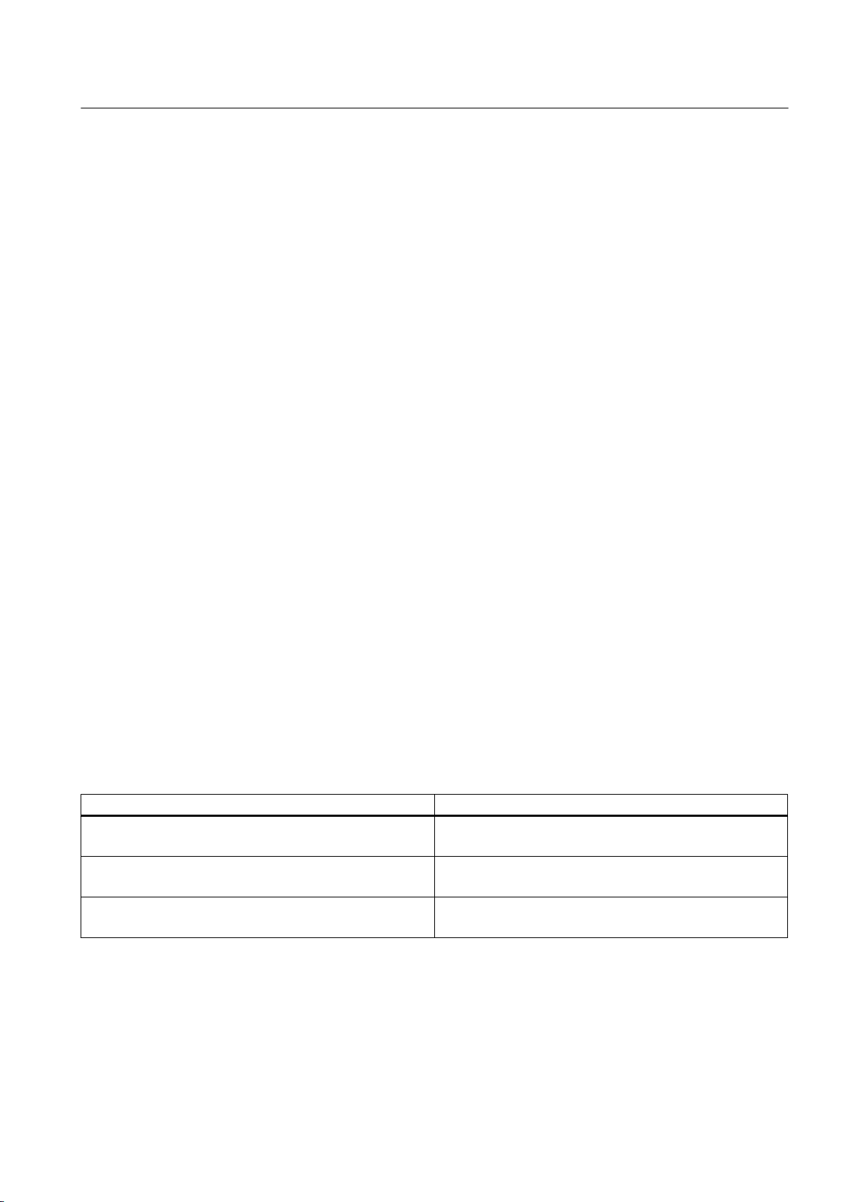
● Up to and including SIMOTION V4.1 SP5, all D410/D4x5 onboard I/Os configured as digital
outputs are exclusively available to SIMOTION
●
As of SIMOTION V4.2, D410/D4x5 onboard I/Os configured as digital outputs can be
switched over to SINAMICS using BICO interconnection (channel granular)
Standard digital output (DO)
The output cam calculations are performed in processing cycles (IPO or IPO_2 cycle clock or
servo cycle clock).
Actual cam output is performed in servo cycles. The temporal resolution of the cam output is
usually reduced by the output cycle of the I/O used.
Therefore the resolution
● with standard I/O (e.g. ET 200) depends on the cycle time of the bus system (PROFIBUS
DP / PROFINET IO)
● with TM15 / TM17 depends on the cycle time of the bus system (PROFIBUS Integrated /
PROFIBUS DP / PROFINET IO)
● with TM15 DI/DO, TM31, TM41, TB30 depends on the configured sampling time
Cam Track TO - Part II
4.2 TO Cam Track basics
– cu.p0799 (CU inputs/outputs sampling time) for the TB30 and onboard outputs
– p4099 (TMxx inputs/outputs sampling time) for TM15 DI/DO, TM31 and TM41
Hardware supported
● Onboard outputs (SIMOTION D, Controller Extension CX, SINAMICS Control Unit CU3xx)
● Centralized I/O (SIMOTION C)
● Distributed I/O via PROFIBUS DP / PROFINET IO (e.g. ET 200, etc.)
● Drive I/O TM15, TM15 DI/DO, TM17 High Feature, TM31, TM41, TB30
Configuration data of cam output types in expert list
Table 4-3 Setting options for cam output
Selection in configuration screen Setting in expert list
Cam output (CAM)
(TM15/17, D410-2, D4x5-2)
High-speed digital output (DO)
(D4xx, C240)
Standard digital output (DO)
(Standard DO, e.g. ET200, TM31)
OcaBaseCfg.outputType = [1] TIME_STAMP
OcaBaseCfg.hwTimer = [91] NO
OcaBaseCfg.outputType = [0] STANDARD
OcaBaseCfg.hwTimer = [173] YES
OcaBaseCfg.outputType = [0] STANDARD
OcaBaseCfg.hwTimer = [91] NO
Output cams on cam output (CAM) or on high-speed digital output (DO) are also referred to
below as high-speed, hardware-supported output cams.
Output Cams and Measuring Inputs
Function Manual, 04/2014 75
Page 76
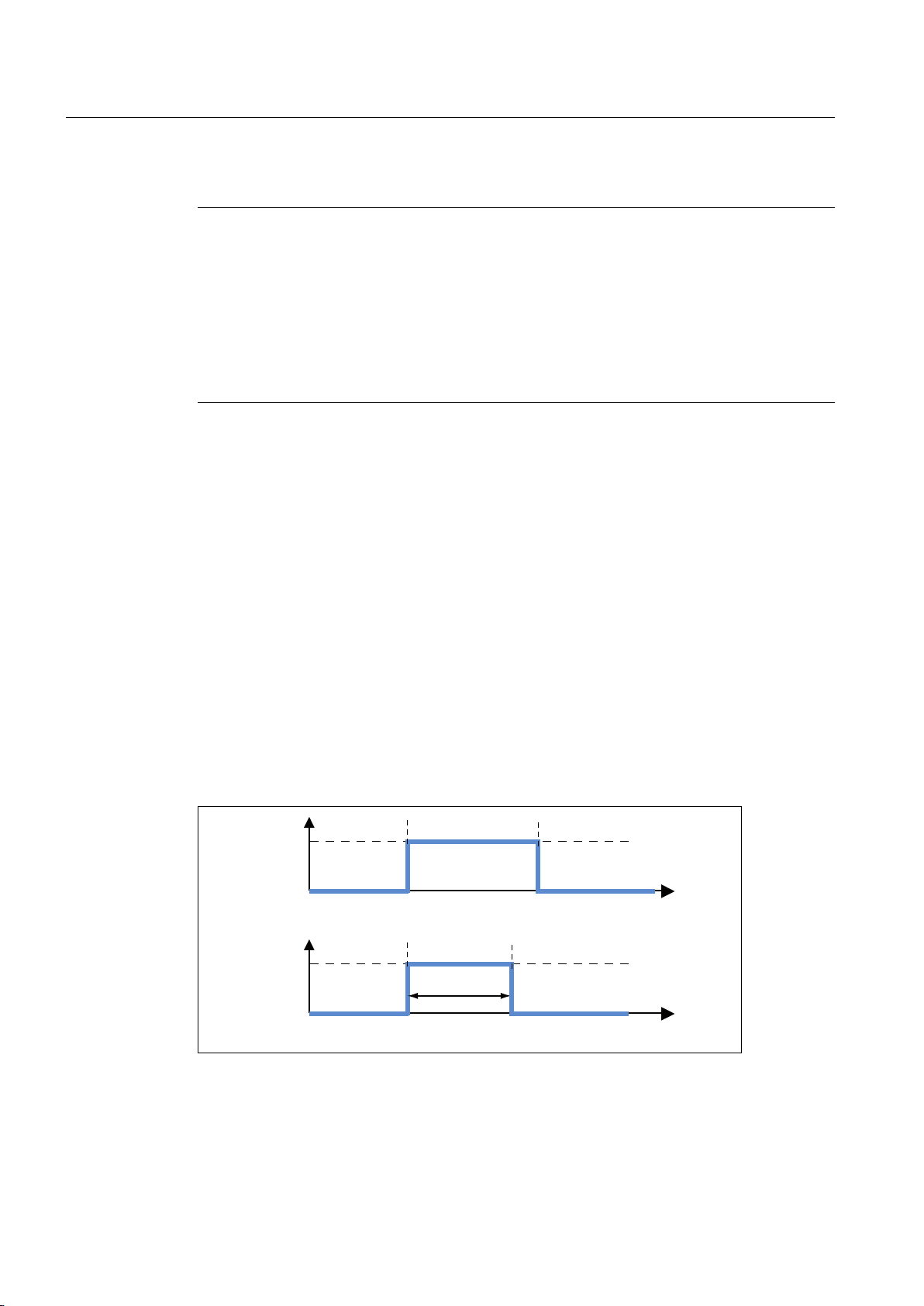
2&
2&
3RVLWLRQ
EDVHGFDP
3RVLWLRQ[
6WDUWLQJ
SRVLWLRQ
(QGSRVLWLRQ
7LPHEDVHG
RXWSXWFDP
3RVLWLRQ[
6WDUWLQJ
SRVLWLRQ
'XUDWLRQ
Cam Track TO - Part II
4.2 TO Cam Track basics
Note
Further information and the output accuracy for high-speed output cams is described in the
PM21 Catalog and in the respective product brief or commissioning/equipment manuals.
Commissioning Manual
Operating Instructions
Commissioning Manual
Commissioning Manual
Commissioning and Hardware Installation Manual
Commissioning and Hardware Installation Manual
4.2.3 Cam track parameters
4.2.3.1 Track length
The camTrackLength
is calculated from the start of the cam track (always 0) to the end of the cam track. Usually,
the output cams of the cam track are located within the track length. The track length must not
be 0. When track length = 0, an error is reported when the cam track of a non-modulo axis is
activated. If track length = 0 for a modulo axis during cam track activation, the cam track length
is set to the axis modulo length.
Terminal Modules TM15/TM17 High Feature
SIMOTION C2xx
SIMOTION D410
SIMOTION D410-2
SIMOTION D4x5
SIMOTION D4x5-2
system variable is used to parameterize the track length. The track length
4.2.3.2 Effective direction and behavior
The following diagram shows output cam behavior on switching on and off, without hysteresis,
activation or deactivation time.
76 Function Manual, 04/2014
Figure 4-9 Output cam behavior on switching on/off
switching
The
The cams on a cam track switch independently of the direction of motion, i.e. they always have
characteristic depends only on the position (position setpoint or actual position).
Output Cams and Measuring Inputs
Page 77
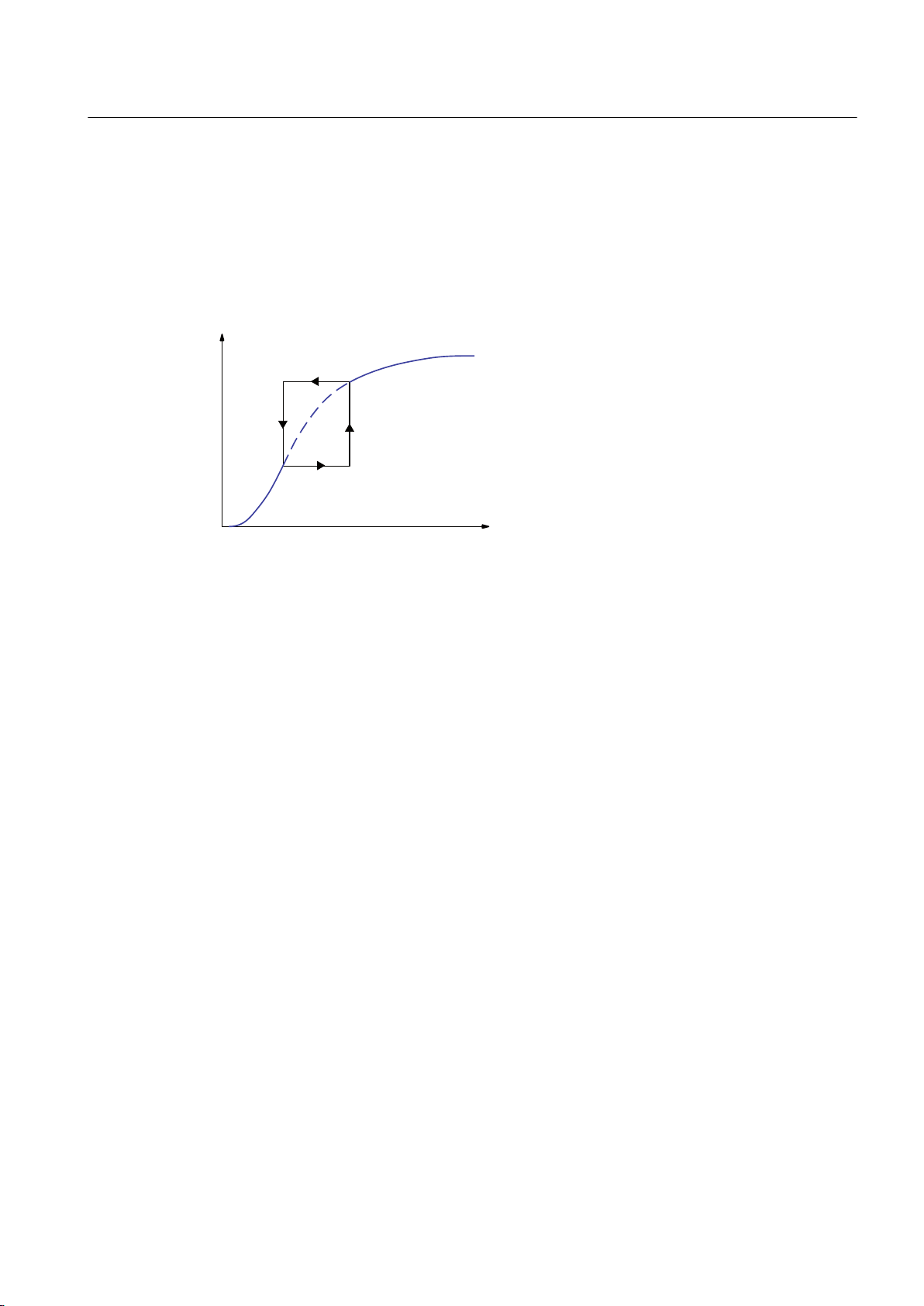
$FWXDOSRVLWLRQ
YDOXH
Cam Track TO - Part II
4.2 TO Cam Track basics
a positive and negative effective direction. A position-based cam can be output repeatedly on
changing the direction of movement. Time-based cams are output once only.
4.2.3.3
Hysteresis
If the actual position value tends to fluctuate due to mechanical influences, specification of a
hysteresis prevents the output cam from unintended switch status changes.
Figure 4-10 Hysteresis
Conditions for the hysteresis range
● Hysteresis is not activated until the direction has been reversed.
● The direction of motion is not redefined within the hysteresis.
● Within the hysteresis, the switching state of position-based cams is not changed.
● If modified switching conditions for the output cam are detected when the output cam is
outside the hysteresis range, this current switching state is set.
Example: position-based cam hysteresis
Cam track configuration (only one output cam configured):
Output cam type: position-based cam; switch-on position, 20 mm; switch-off position, 200 mm;
hysteresis, 20 mm; effective direction: both
Axis positions:
0 mm -> 100 mm -> 10 mm -> 50 mm -> 0 mm -> 150 mm -> 0 mm
Output Cams and Measuring Inputs
Function Manual, 04/2014 77
Page 78
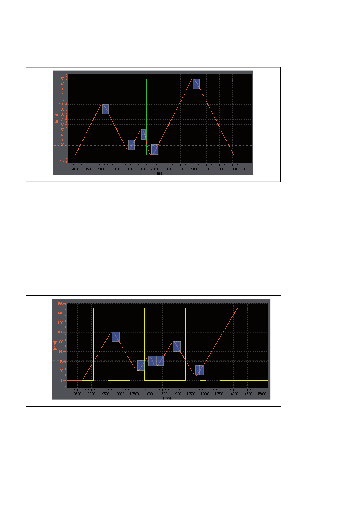
Hysteresis
Actual position of axis
X
ST
ART
Switching state of output cam
+\VWHUHVLV
$FWXDOSRVLWLRQRID[LV
;
VWDUW
6ZLWFKLQJVWDWHRIWLPHEDVHGFDP
2XWSXWFDP
GRHVQRWVZLWFK
Cam Track TO - Part II
4.2 TO Cam Track basics
Figure 4-11 Hysteresis range (height of blue sections) and behavior of a cam track with a position-based cam, effective
direction in both directions.
As the cam track switches in both directions, the output cam does not switch off after the first
reversal of direction. The second switch-on point is moved to position 30, due to active
hysteresis.
Example: time-based cam hysteresis
Cam track configuration (only one output cam configured):
Output cam type: time-based cam; switch-on position, 40 mm; ON duration, 0.5 s; hysteresis,
20 mm; effective direction: both
Axis positions:
0 mm -> 100 mm -> 20 mm -> 50 mm -> 30 mm -> 80 mm -> 10 mm -> 150 mm
Figure 4-12 Hysteresis range (height of blue sections) and behavior of a cam track with one time-based cam, no effective
direction.
Time-based cam
switches off only after ON duration has expired, not after change of direction.
78 Function Manual, 04/2014
Output Cams and Measuring Inputs
Page 79

Cam Track TO - Part II
4.2 TO Cam Track basics
Time-based cams with a start position within the hysteresis range are not output (see figure
above).
Hysteresis range
The upper
limit of the hysteresis range is set at 25% of the working range for a linear axis, and
25 % of the rotary axis range for a rotary axis. If you violate this maximum setting, an error
message is issued. In practice, a lower setting is used for the hysteresis range.
● Path-controlled output cam
The hysteresis becomes active after direction reversal is detected. The output cam switches
off once the hysteresis has been left and the position is located outside of a defined output
cam.
● Time-based cam
The switching behavior of a time-based cam is determined by the ON duration, not by the
hysteresis. This means that an entered hysteresis range has no influence on the ON
duration of an output cam. It only has an influence on the switch-on time (start position).
● Time-based cam with maximum ON length
The maximum ON length switches off the output cam once the hysteresis has been left and
the maximum ON length has been exceeded.
Note
If a time-based cam's start position lies within the hysteresis, it is not output.
4.2.3.4 Derivative-action times (activation time/deactivation time)
To compensate for the switching times of digital outputs and connected switching elements,
or
propagation delays, it is possible to specify actuation times. Actuation times are calculated
of
from the sum of all delay times and can be specified separately for activation and deactivation
edges as an actuation time at the activation edge (activation time) or an actuation time at the
deactivation edge (deactivation time).
The activation/deactivation times of the output cam are dynamically compensated by means
of the derivative-action times. In this way, output cams are dynamically shifted depending on
the actual velocity.
For example, a valve that should open at 200°, with an activation time of 0.5 s
● Must be controlled at 195° at a velocity of 10°.
● Must be controlled at 190° at a velocity of 20°.
This dynamic shift takes place automatically by means of the TO camTrack.
Settings for the activation and deactivation times can contain positive or negative values.
A negative activation time must be entered if the output cam is to be switched before the
programmed start of the output cam.
Output Cams and Measuring Inputs
Function Manual, 04/2014 79
Page 80
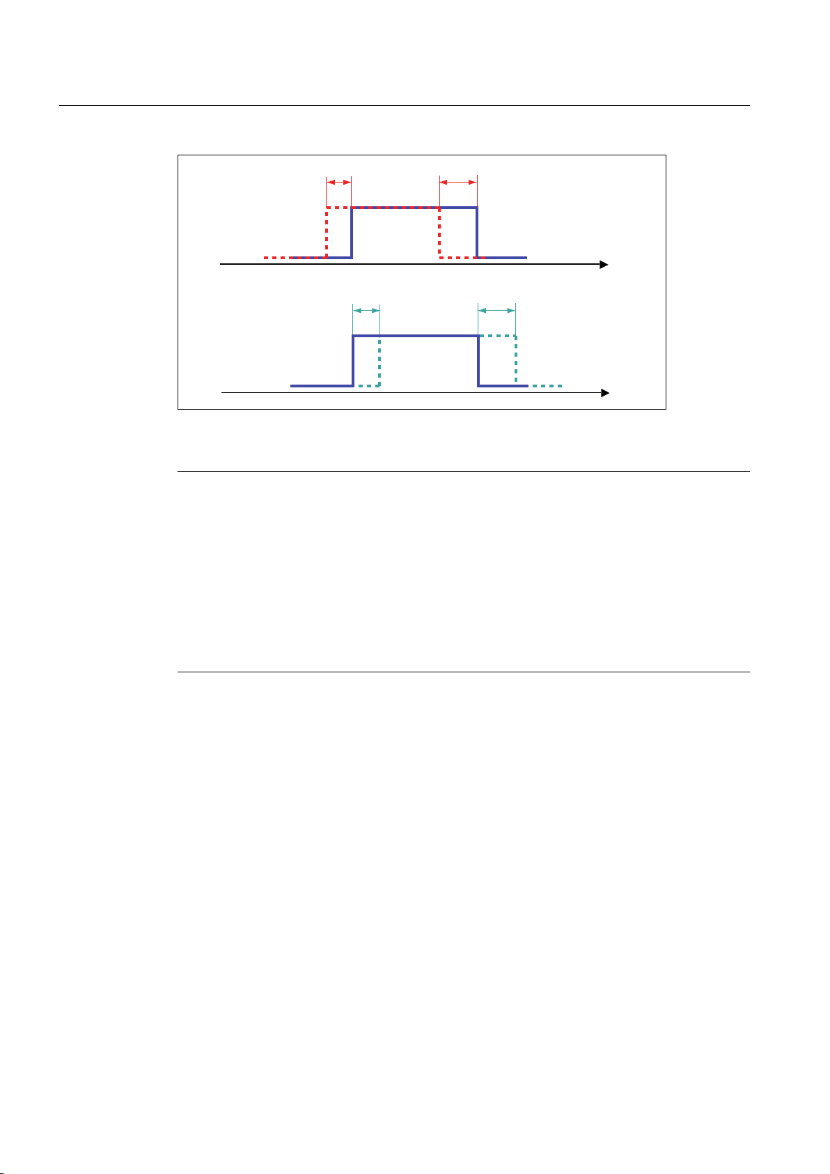
'HDFWLYDWLRQWLPH
$FWLYDWLRQWLPH
'HDFWLYDWLRQWLPH
$FWLYDWLRQWLPH
Cam Track TO - Part II
4.2 TO Cam Track basics
Figure 4-13 Switching behavior at varying actuation times
Note
The time
of output for the output cam in the controller is relevant for calculation of the dynamic
adjustment. If velocity changes up to signal output, these changes are no longer taken into
account.
Dead times, e.g. PROFIBUS DP communication times, output delay times on digital outputs,
etc., are taken into account in the actuation time.
Long actuation times exceeding one modulo cycle may lead to heavy fluctuation of the
switching position of actual value output cams (actual value curve). Here, setpoint output
cams should be used or the actuation time should be considerably less than one modulo
cycle.
The system takes into account the specified actuation times when the output cams are
calculated and
managed. The switching positions of the output cams are calculated taking into
account the activation time and deactivation time in relation to the present velocity. If, allowing
for actuation times, the output cam was switched, then the system deems this operation to
have occurred, and it does not switch the output cam again even if any subsequent current
velocity changes occur.
The dynamic actuation of modulo axes can be greater than one modulo length. However, the
number of switching operations is not collected by the system, i.e. for actuation times longer
than one modulo length, a switching operation cannot take place in each modulo cycle. One
switching operation is active in the system at any given point in time. A switching operation is
completed when the output cam is switched off.
Actuation times and cycle clock settings
A change of cycle clock settings does not have to be taken into account for the actuation time
settings (activation/deactivation time). These are, for example:
Output Cams and Measuring Inputs
80 Function Manual, 04/2014
Page 81

Cam Track TO - Part II
4.2 TO Cam Track basics
● Changing the
ms").
● Change of processing cycle clock of the cam track TO (setting: Servo cycle clock, IPO cycle
clock or IPO_2 cycle clock).
Deactivation time for time-based cam
Deactivation time is also taken into account in setting a time-based cam.
Deactivation time must be:
● Deactivation time ≤ activation time + ON duration
Activation and deactivation times can vary independently of the I/O and can, therefore,
influence the ON duration of the time-based cam.
4.2.3.5 Cam track activation
The _enableCamTrack command activates the cam track. On activation, the defaults are
transferred to the system variables. If you explicitly want to use other values, these must be
transferred with the command.
The following parameters are transferred via the _enableCamTrack command:
Servo/IPO/IPO_2 cycle clock settings (for example, from "1/1/1 ms" to "2/2/2
● Cam track data
● Output cam data
If you do not transfer any new data when activating the command, the defaults are used.
4.2.3.6 Cam track deactivation
Cam tracks are deactivated automatically or via a command.
Automatic deactivation
Automatic cam track deactivation is only possible when the configuration data
octBaseCfg.keepEnabledOutOfTrackRange has been set to NO. In this case deactivation
occurs on exiting the domain of the cam track, i.e. the track start (in a negative direction) or
the track end (in a positive direction). It is not possible to reverse the direction of movement
repeatedly within the track length. Output cams can therefore be output repeatedly. Automatic
deactivation is set as default. As of V4.1 you can set the deactivation via the configuration data.
Note
In the cam track Configuration window, you can configure the automatic deactivation via
Leave non-cyclic activated cam track active in the axis range.
Deactivation via command
The _disableCamTrack command is used to deactivate the cam track.
Output Cams and Measuring Inputs
Function Manual, 04/2014 81
Page 82
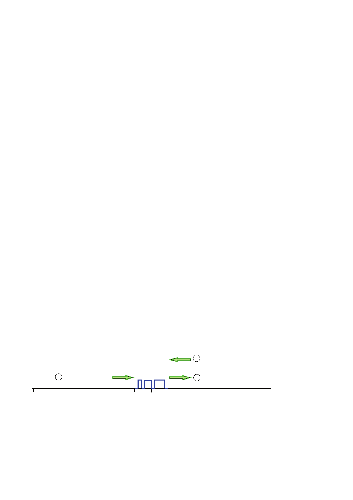
&DPWUDFNLV
DFWLYDWHGQRQ
F\FOLFDOO\
$[LVWUDYHUVHVRXWVLGH
RIFDPWUDFNOHQJWK
&DPWUDFNVZLWFKHV
DJDLQDIWHUGLUHFWLRQ
UHYHUVDO
Cam Track TO - Part II
4.2 TO Cam Track basics
You can parameterize the deactivation time for the _disableCamTrack command
Start mode and stop mode).
4.2.3.7 Leave cam track active in the axis range (as of V4.1)
Non-cyclic activated cam tracks are deactivated per default when the cam track length is exited.
So that the non-cyclic cam track remains active over the entire axis range (also outside of the
cam track length), you must set the configuration data
octBaseCfg.keepEnabledOutOfTrackRange to YES. When the cam track length is exited, the
non-cyclic cam track remains active and is deactivated, for example, via command.
Note
In the
cam track Configuration window, you can deselect the automatic deactivation via Leave
non-cyclic activated cam track active outside of the track range.
Features
● Valid for modulo axes and non-modulo axes
With modulo axes, the cam track is only switched in the appropriate modulo range of the
●
axis, and not in every modulo range. This also ensures a clear assignment when cam track
lengths ≥ modulo length.
● Value=NO: Non-cyclic cam track is only active within the cam track length.
If the axis or external encoder moves out beyond the cam track length, the cam track is
deactivated. Returning to this length triggers new switching operations.
(see Section
● Value=YES: Non-cyclic cam track is active over the entire axis range, also after leaving the
cam track length If the axis or external encoder moves out beyond the cam track length
and then back into the cam track range, the configured output cams switch again.
Example
There is a linear axis (non-modulo axis) with a traversing range of -1000 mm to 1000 mm and
a cam track with a track length of 200 mm (-100 mm to 100 mm). The cam track is to remain
active over the entire axis range and the cam track is to be activated non-cyclically.
After the cam track is exited (2), it remains active and is switched again after the reversal of
direction (3) (see figure below).
Figure 4-14 Leaving cam track active over the entire axis range
82 Function Manual, 04/2014
Output Cams and Measuring Inputs
Page 83

4.2.3.8 Start mode and stop mode
Cam Track TO - Part II
4.2 TO Cam Track basics
Start mode
and stop mode are used to parameterize behavior on activation or deactivation of
a track.
Start mode
The start mode (startMode) is used to define when the cam track should become effective
after activation, or how tracks should be changed.
The mode is defined either as part of the cam track configuration in the Default window, or
directly as a default setting using the _enableCamTrack command.
Table 4-4 Types of start mode
Start mode Description
Effective immediately (default)
(IMMEDIATELY)
Immediately when cam track
output inactive
(IMMEDIATELY_BY_CAM_TRA
CK_OUTPUT_INACTIVE)
With next track cycle
(NEXT_CAM_TRACK_CYCLE)
Last programmed value
(EFFECTIVE)
Track becomes active immediately. If an output cam (or time-based cam) is defined or
active at the current position of the old track, the output is aborted. The new track is
enabled without delay (as quickly as possible). This enables high-speed exchange of
cam tracks.
If an output cam is already controlled and new data from the exchanged cam track
continues to control the track signal, the track signal is not interrupted.
Changeover is made to the new cam track if no single output cam is active (any longer)
on the old cam track. An active (output) single output cam on the old cam track is still
output completely.
changeover to the new track has not been made at the start position of a single output
If a
cam on the new track, this output cam is not output. Only after the tracks have been
exchanged are the subsequent output cams on the new track output.
Track does not become active until the next track cycle, after either the axis reference
position (in the positive traversing direction) or the end position of the cam track (in the
negative traversing
position of the new track. Immediately the first output cam on the new track switches, a
changeover is made to the new track. Up to that point, a time-based cam on the old track
is output.
The previous cycle is processed according to the previous command, the next cycle
according to the _enable command. This allows the next track to be enabled, although
another track is currently being processed.
It is necessary to use this mode if the enable must occur before the start of the new cam
track, for example, if the first output cam lies at the very start, but an output cam at the
very end of an old (inactive) track is not to be enabled by mistake.
The last programmed stop mode is active. If a stop mode is not programmed, the user
default setting is used.
direction). The cam track end of the old track equals the axis reference
Changing cam track output on the basis of the selected start mode
The effect of the start mode on cam track output is shown in the following table for two cam
tracks. The examples refer to activation of the same cam track with new or modified data.
Output Cams and Measuring Inputs
Function Manual, 04/2014 83
Page 84
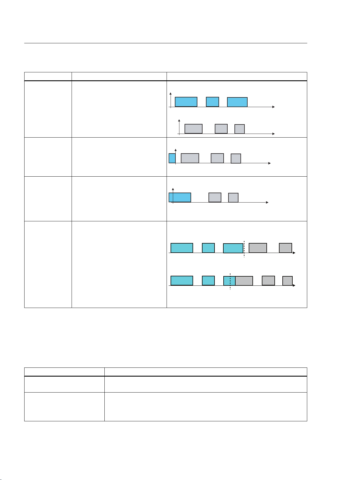
$
%
&
$
$
$b
%
&
$b
%
&
(QGRIFDPWUDFN
(QGRIFDPWUDFN
([DPSOH
([DPSOH
Cam Track TO - Part II
4.2 TO Cam Track basics
Table 4-5 Start mode examples
Mode Description Display on cam track output
One cam track with different data is
given.
● Cam track 1 (A to C)
active cam track.
●
Cam track 2 (1 to 3)
is activated.
Effective
immediately
(IMMEDIATELY)
Cam track output
inactive
(IMMEDIATELY_B
Y_CAM_TRACK_
OUTPUT_INACTI
VE)
With next track
cycle
(NEXT_CAM_TRA
CK_CYCLE)
● New cam track becomes active
immediately.
● Cam track output becomes inactive.
Output cams 1, 2 and 3 are output.
●
● New cam track becomes active at a
cam track output of zero.
Output cam A on the active track is
●
output completely.
●
Output cams 2 and 3 are output.
● Output cam 1 is not output.
● Cam track is exchanged at the axis
reference position of the new cam
track.
● Example 1, position-based cam:
Position-based cam of the old track
is terminated.
Example 2, time-based cam:
●
New cam track becomes active with
the first output cam of the new track,
at the latest. Up to that point, timebased cams remaining from the old
cam track are still output.
Stop mode
The stop mode (stopMode) is used to define the behavior of the cam track on deactivation.
The mode is defined either as part of the cam track configuration in the Default window, or
directly as a default setting using the _disableCamTrack command.
Table 4-6
Stop mode Description
Effective immediately (default)
(IMMEDIATELY)
Immediately when cam track
output inactive
(IMMEDIATELY_BY_CAM_TRA
CK_OUTPUT_INACTIVE)
84 Function Manual, 04/2014
Types of stop mode
Track is deactivated immediately. If an output cam (or time-based cam) is defined or
active at the current position of the track, the output of output cam is aborted.
If
no single output cam is active (any longer), the active cam track is stopped. An active
(output) single output cam is still output completely.
Output Cams and Measuring Inputs
Page 85
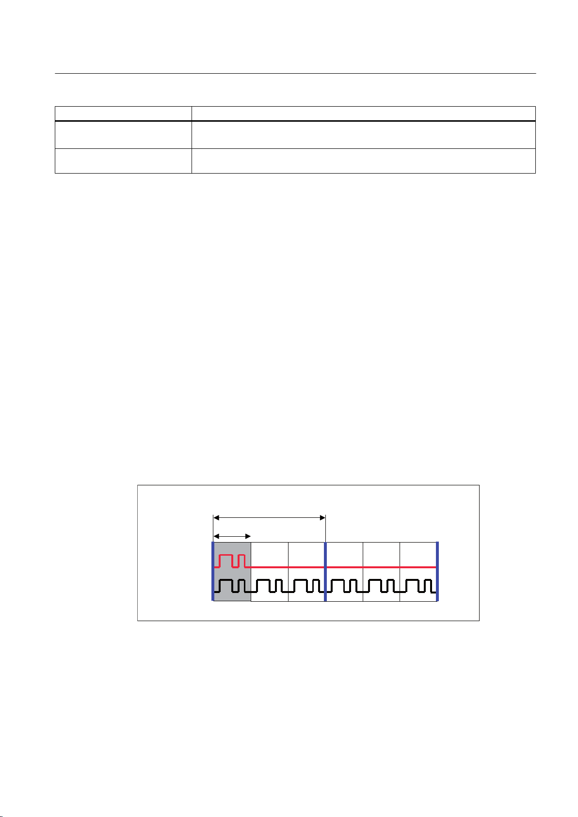
Stop mode Description
1RQF\FOLF
2XWSXW
&\FOLF
2XWSXW
7UDFNr
0RGXORD[LVr
&DPWUDFNLVPDSSHGRQWRPRGXOROHQJWK
RID[LVWKUHHWLPHV
At end of cam track
(BY_CAM_TRACK_END)
Last programmed value
(EFFECTIVE)
Track is deactivated at its end. Immediately the final output cam on the track switches,
the track is deactivated. Up to that point, a time-based cam on the track is output.
The last programmed start mode is active. If a start mode is not programmed, the user
default setting is used.
4.2.3.9 Output activation mode
Cam Track TO - Part II
4.2 TO Cam Track basics
Cam tracks
can be output in a cyclic or non-cyclic mode. This setting is also transferred when
activating the cam tracks (_enableCamTrack)
Cyclic output
The CYCLIC setting in the activationMode parameter is used to predefine the activation mode
for cyclic output of the cam track.
The cam track's track length is mapped from the start position and continued/repeated
cyclically. The cam track switches after the axis reference position and remains active until it
is switched off with _disableCamTrack.
Non-cyclic output
The NO_CYCLIC setting in the activationMode parameter is used to predefine the activation
mode for non-cyclic output of the cam track.
The cam track is mapped from the start position, output once only and terminated automatically
after reaching the end position or remains active in the axis range. The performance depends
on the value of the configuration date octBaseCfg. keepEnabledOutOfTrackRange.
Example of cyclic and non-cyclic output
A cam track is mapped onto a modulo axis. The figure shows a representation of the different
activation modes.
Figure 4-15 Example of cyclic and non-cyclic output on a modulo axis
4.2.3.10 Axis reference position and cam track offset
Cam tracks are defined independently of the axis. Output cams are not calculated according
Output Cams and Measuring Inputs
Function Manual, 04/2014 85
to the defaults until they are mapped onto the axis. The
(enableCamTrack.axisReferencePosition) axis reference position is used to define from which
Page 86

Cam Track TO - Part II
4.2 TO Cam Track basics
position on the axis the cam track should be output. The axis reference position value can be
negative or positive. The cam track is always output relative to this position data.
The axis reference position enables you to offset the cam track on the axis as you wish, and
therefore to define when the output should take place (see figure in Section Cam track
features
A cam track is mapped to the axis range exactly once, beginning with the axis reference
position specified in the enable command. This axis reference position represents the
beginning of the cam track (applies for modulo and non-module axes). Upon activation, the
cam track is executed once (NO_CYCLIC) or continued cyclically (CYCLIC).
4.2.3.11 Simulation
Operation can be simulated by means of the simulation commands on the cam track. The cam
track status is then not output to the hardware output. In simulation mode, hardware cams
behave as software cams. They are then only used for programming purposes.
If an active cam track is switched to simulation mode (_enableCamTrackSimulation), the output
cam status remains the same, and only the control of the output is reset or interrupted.
).
4.2.4 Configure Units
You can define the basic units for each technology object. The same physical variables can
have different units in different technology objects. These are converted:
How to configure the units:
1. In the project navigator, open the context menu for the technology object.
2. In the context menu, select Expert > Configure units. The Configure Units window appears
in the working area.
3. Select the unit for the physical variables. These units are used for the technology object,
e.g. s for time units.
or
1. In the project navigator, open the Configuration under the TO.
2. Select the Units tab.
Output Cams and Measuring Inputs
86 Function Manual, 04/2014
Page 87
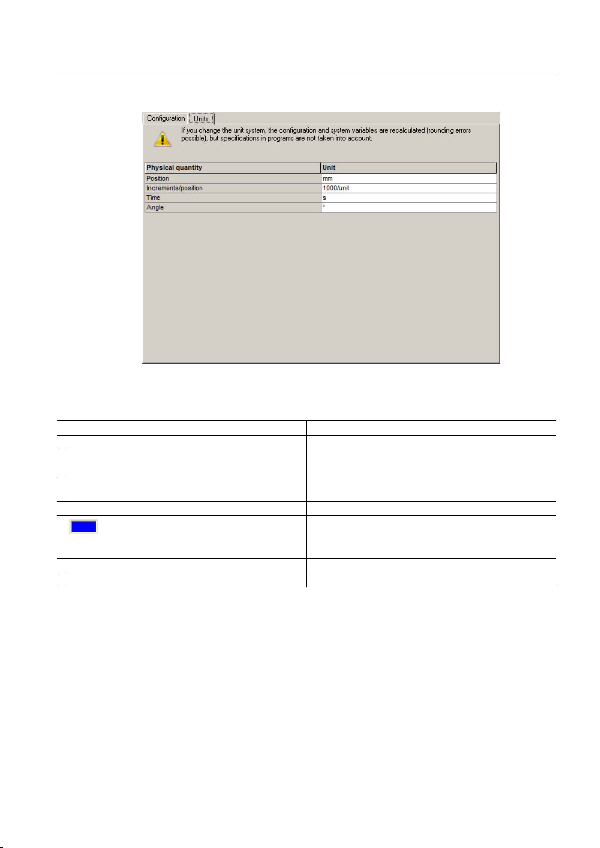
Cam Track TO - Part II
4.2 TO Cam Track basics
You can set the following parameters:
Field/button Meaning/instruction
Table with units
Physical variable column Shows the physical variable. The physical variables which
are used by the TO are available for the configuration.
Unit column Displays and configures the unit. A drop-down list for
selecting the unit appears when you click on the cell.
Toolbar
Close Button for closing the dialog.
Help Button for opening the online help for the dialog.
Displays whether offline data or online data is shown
● Blue field = offline display
Yellow field = online display
●
4.2.5 Mapping a cam track onto an axis
The cam track is defined independently of the axis. On activation, the cam track is mapped
onto the axis. Only then are the switching states of the output cams calculated.
Output Cams and Measuring Inputs
Function Manual, 04/2014 87
Page 88
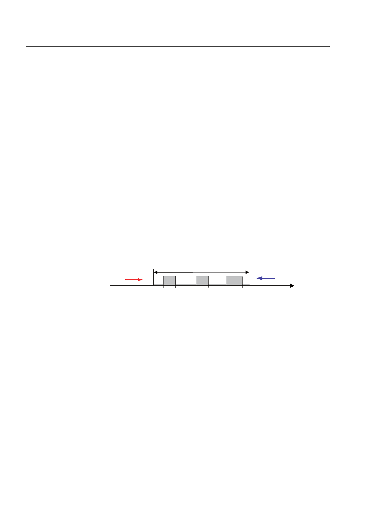
2&
2&
2&
&DPWUDFNFDP7UDFN7\SH
$[LVSRVLWLRQ
1HJDWLYHGLUHFWLRQRI
URWDWLRQRID[LV
3RVLWLYHGLUHFWLRQRI
URWDWLRQRID[LV
2Q
2II
2Q
2II
2Q
2II
2II
2Q
2II
2Q
2II
2Q
6ZLWFKLQJVWDWHRIRXWSXWFDP
6ZLWFKLQJVWDWHRIRXWSXWFDP
Cam Track TO - Part II
4.2 TO Cam Track basics
See also
Basics of cam track mapping (Page 88)
Mapping output cams onto the cam track
Mapping onto negative axis positions (e.g. linear axes) (Page 89)
Relation of track length, modulo length and activation mode in mapping (Page 90)
4.2.5.1 Basics of cam track mapping
● Conversion and mapping of the track onto the axis is identical for modulo and non-modulo
axes. Certain points must be noted when mapping onto negative reference positions (see
Section Mapping onto negative axis positions (e.g. linear axes)).
● The track length can be longer than, shorter than or equal to the modulo length of the axis.
Based on this relationship, the switching states of the output cams may differ when they
are mapped onto the axis.
● The positions of single output cams always relate to the cam track, not to the axis position.
Only on activation of the cam track and entry of the axis reference position is a relationship
to the axis position created (start of cam track output).
● If the cam track is activated and the axis rotates negatively, the track will also travel in a
negative direction. There is no conversion on the basis of the direction of rotation (see
figure). If a cam track should always be output in a positive direction, irrespective of the
axis direction, this must be solved in the application.
(Page 88)
4.2.5.2
88 Function Manual, 04/2014
Mapping output cams onto the cam track
Figure 4-16 Cam track in positive and negative direction, depending on axis direction
● Cam tracks defined outside of the track length limits are mapped or converted during
mapping onto the track range.
The _enableCamTrack command is used to map the starting and end positions of the output
cam individually onto the cam track (not onto the axis). Output cams, which have been defined
outside of the track range, are converted to this track. Negative starting and end-position values
are also converted to the cam track.
Output Cams and Measuring Inputs
Page 89
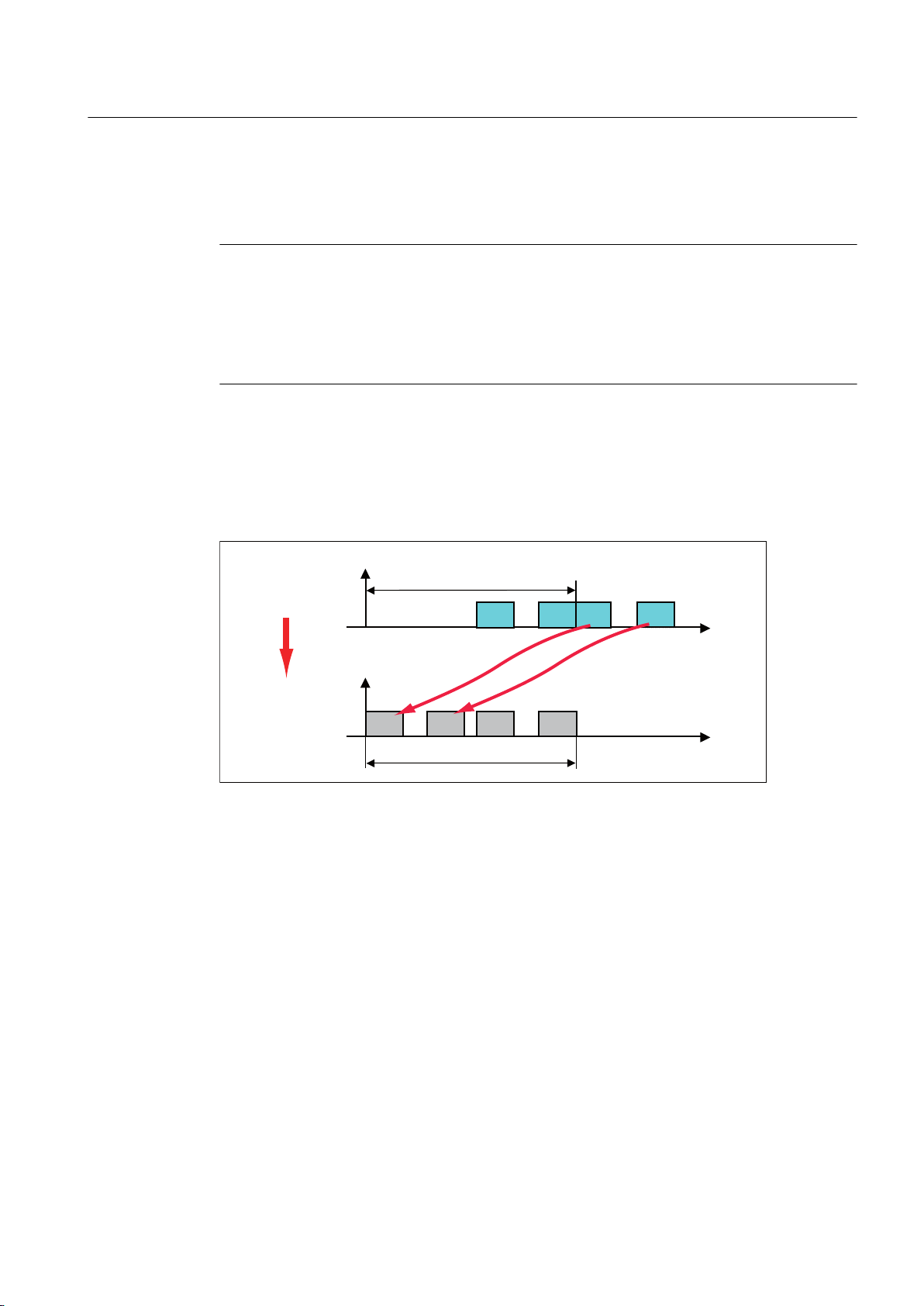
2&
2&
2&
2&
2&2&
2&
7UDFNOHQJWK
&DPWUDFNFDP7UDFN7\SH
&DPWUDFNFDP7UDFN7\SH
&DPWUDFN
GHILQLWLRQ
$IWHU
PDSSLQJRQ
WKHD[LV
7UDFNOHQJWK
Cam Track TO - Part II
4.2 TO Cam Track basics
"Unfavorable" starting and end-position default settings for output cams, e.g. output cam
position outside
being created. This must be taken into account when mapping the cam track onto the axis.
Note
of the track range, can lead to output cams being shifted, or new output cams
After converting
the cam track onto the axis, the effective output cam length is always shorter
than or equivalent to the track length. No output cams are defined outside of the track length.
For standard applications, and in the interests of clear programming, automatic conversion
of output cams should be avoided. This can be achieved by only defining output cams, which
lie within the track length.
Mapping example
A cam
track with three output cams (OC1 - OC3) is provided. The end position of output cam
OC2 and the entire output cam OC3 are defined outside of the track length. After being mapped
onto the axis, OC3 is converted to the track length and mapped to position OC3*. A new output
cam OC4* arises from partial output cam OC2.
Figure 4-17 Parts of cam track lie outside of the track length
4.2.5.3 Mapping onto negative axis positions (e.g. linear axes)
Output cams on the cam track are always predefined positively. If you want to output output
cams at negative axis positions, the cam track output start must be set in the negative range
by means of the axis reference position.
Example of a linear axis with negative axis position
● Range of linear axis: -1000 mm to +1000 mm (non-modulo axis)
● Output of output cam at axis position: -100 mm to -200 mm
● Cam track length: 2000 mm
Output Cams and Measuring Inputs
Function Manual, 04/2014 89
● Definition of the output cam on the track: SOC=800 mm; EOC=900 mm
By mapping the cam track via the axis reference position, the output cam OC1 can be output
at a negative axis position.
Page 90
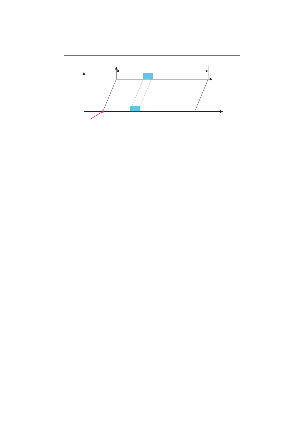
2&
2&
7UDFNOHQJWK PP
&DPWUDFNFDP7UDFN7\SH
$[LV
$[LVUHIHUHQFHSRVLWLRQ
$[LVSRVLWLRQ
LQPP
7UDFN
SRVLWLRQLQ
PP
WR
WR
Cam Track TO - Part II
4.2 TO Cam Track basics
Figure 4-18 Linear axis with output of output cam at negative axis position
Please note
that during cyclic output (CYCLIC), cam tracks are continued cyclically even with
non-modulo axes, and thus the cam track can be output multiple times to different axis
positions.
If a cam track is to remain switched on permanently and only output at one axis position, we
recommend the following setting: cam track length ≥ axis traversing range.
This setting prevents the cam track from being continued cyclically in the case of cyclic output
of a cam track after execution of the track range (in the figure: axis position - 1000 to +1000).
In the above figure, for example, the cam track would be continued cyclically
● in the positive range from axis position 1000 to 3000; 3000 to 5000 etc
● In the negative range from axis position -1000 to -3000; -3000 to -5000 etc.
.
The same behavior applies also for non-modulo rotary axes.
4.2.5.4 Relation of track length, modulo length and activation mode in mapping
In conventional output-cam output (comparable to mechanical cam controllers), the track
length corresponds to the modulo length of the axis and cyclic output takes place.
With electronic cam controllers, the track length can be shorter or longer than the modulo
length of the axis, therefore offering a greater degree of flexibility.
● Track length (tl) < modulo length (m) (integer ratio m to tl)
Track length is output n-fold (n = m/tl) on modulo length.
● Track length (tl) > modulo length (m) (integer ratio tl to m)
Output takes place on every nth rotation (n = tl/m). Output always takes place after the first
quadrant. If the output takes place differently, a greater track length must be defined and
the output cam placed accordingly.
● Non-integer division ratios lead to the cam track being dislocated on every axis rotation.
Output Cams and Measuring Inputs
90 Function Manual, 04/2014
Page 91
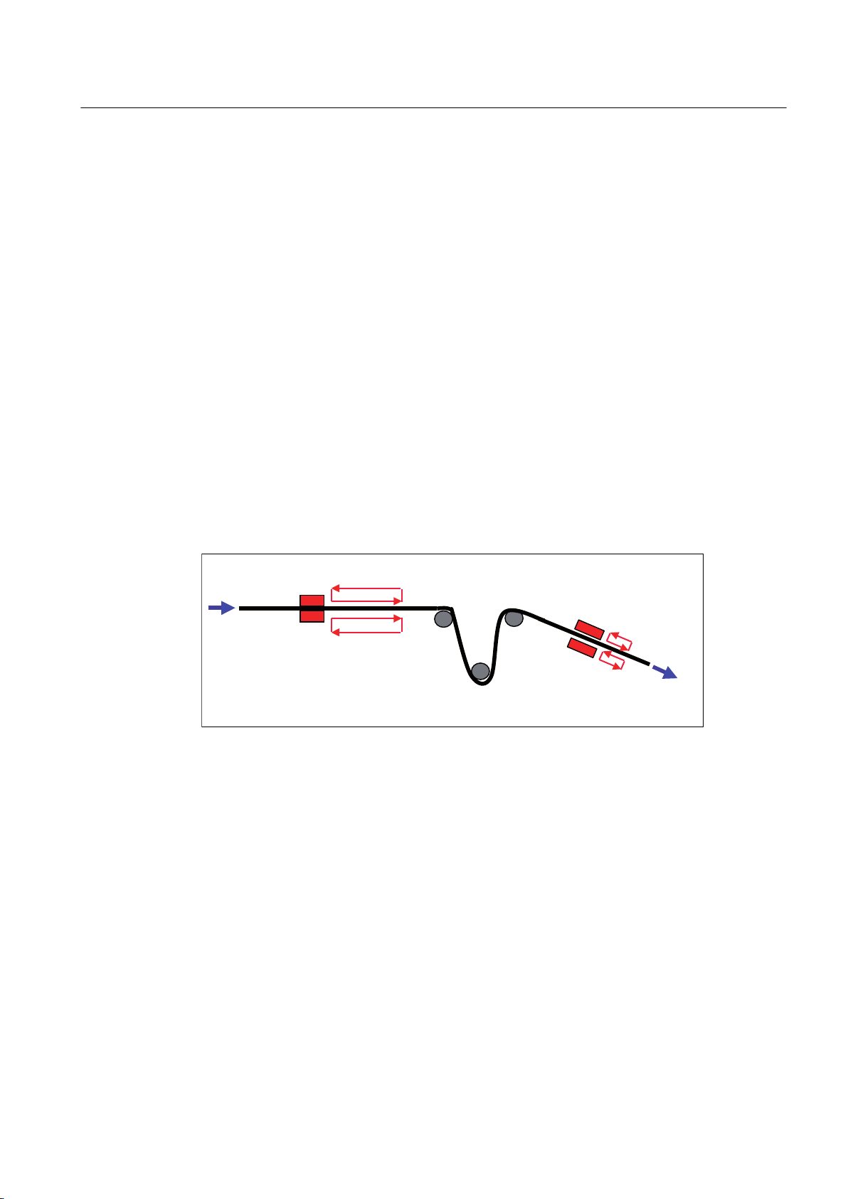
)HHGILQJHUV
%DODQFLQJORRS
)HHGILQJHUV
r PP
)HHGUDWH
[rIHHGLQSHULRGRI
[rIHHG
Cam Track TO - Part II
4.2 TO Cam Track basics
Use of cyclic output with track length = n x modulo length
If the
track length is n times the modulo length, cyclic output allows a repetitive output of output
cam to be easily achieved on every nth rotation (e.g. an air nozzle, which is always activated
in the same angular range on every nth rotation).
Use of cyclic output with track length = 1/n x modulo length
A cycle scan rate is described using the example of a packaging machine with variable product
lengths.
A cam controller controls/triggers all machine functions through a machine cycle of 0-360° (fed
from left-hand area, see figure below). The product lengths may vary and are always mapped
at 360°.
The machine cycle is subdivided into four identical operation steps at an operating station
(right-hand area). The output cam is output cyclically for the operating station, with the track
length = 1/4 modulo length of axis. The output cams on a cam track define the operating steps
for one of the four identical feeds.
The advantage of this solution is that the product defaults are set in mm of the blister length
and calculation/mapping at 360° only has to take place once. In this example, one machine
cycle is used for four purposes. The same outputs are required for one use. Therefore, the
same configuration does not have to be performed four times. Rather, the repetition factor n
is calculated into the track length of the cyclically active track.
Figure 4-19 Packaging machine with reduced cycle
Output Cams and Measuring Inputs
Function Manual, 04/2014 91
Page 92
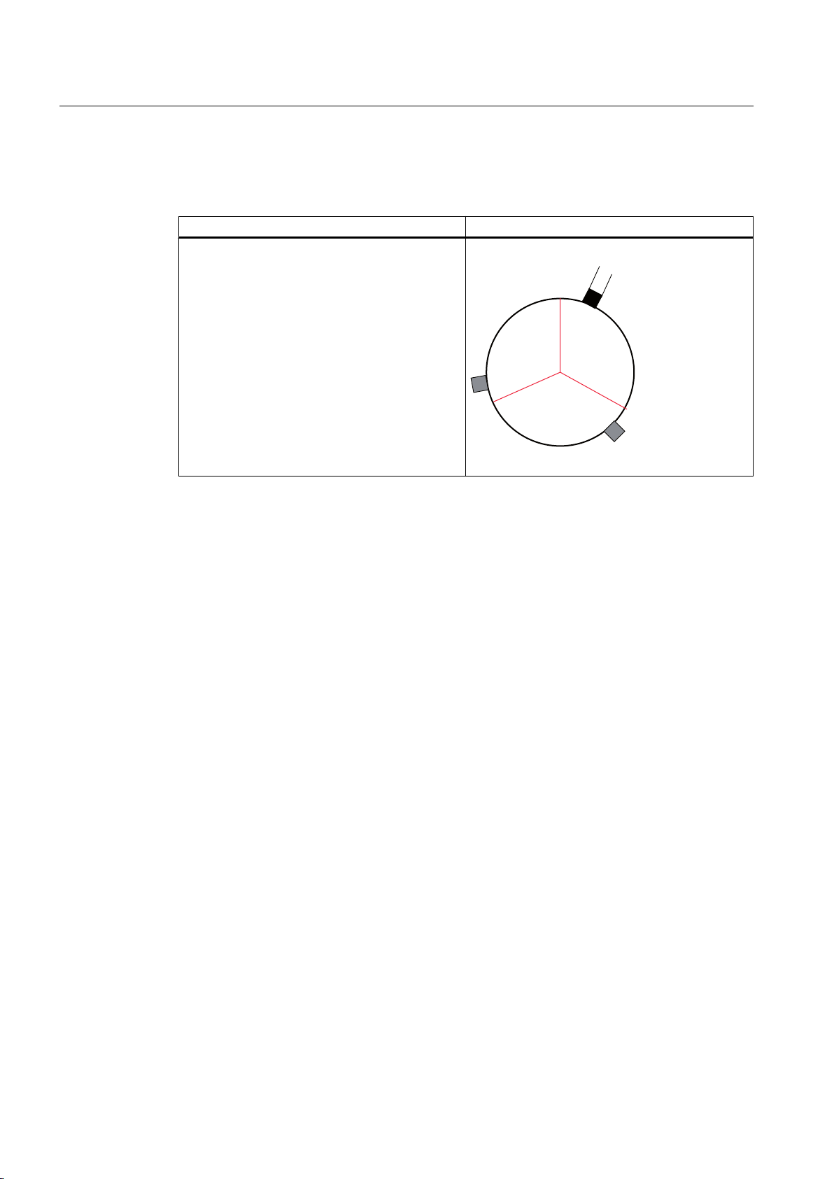
r
r
r
r
2XWSXWFDP
r
Cam Track TO - Part II
4.2 TO Cam Track basics
Example of a modulo axis with cyclic output
Table 4-7 Example of a modulo axis with cyclic output and track length < modulo length
Cam track data/Explanation Representation
●
Modulo length: 360°
● Track length: 0-120°
● Output cam defaults: SOC=10°, EOC=20°
Output cam is output cyclically every 10-20°,
130-140°, 250-260°, etc.
If the direction of movement is reversed at 50°, for
example, the 10-20° output cam will be output
again.
Example of a modulo axis with non-cyclic output
The example (following table) below shows a modulo axis with non-cyclic output, next-track-
cycle start mode, and varying enable positions and axis reference positions.
● Enable A, axis reference position 0°, positive direction of rotation:
output cam A is output.
If the cam track is not exited, output cam A switches multiple times when the direction is
reversed. The cam track output is terminated on exiting the cam track.
● Enable A, axis reference position 240°, negative direction of rotation:
output cam C is output during the next cycle.
● Enable B, axis reference position 120°, positive direction of rotation:
output cam B is output.
● Enable C, axis reference position 240°, positive direction of rotation:
output cam C is output.
Output Cams and Measuring Inputs
92 Function Manual, 04/2014
Page 93
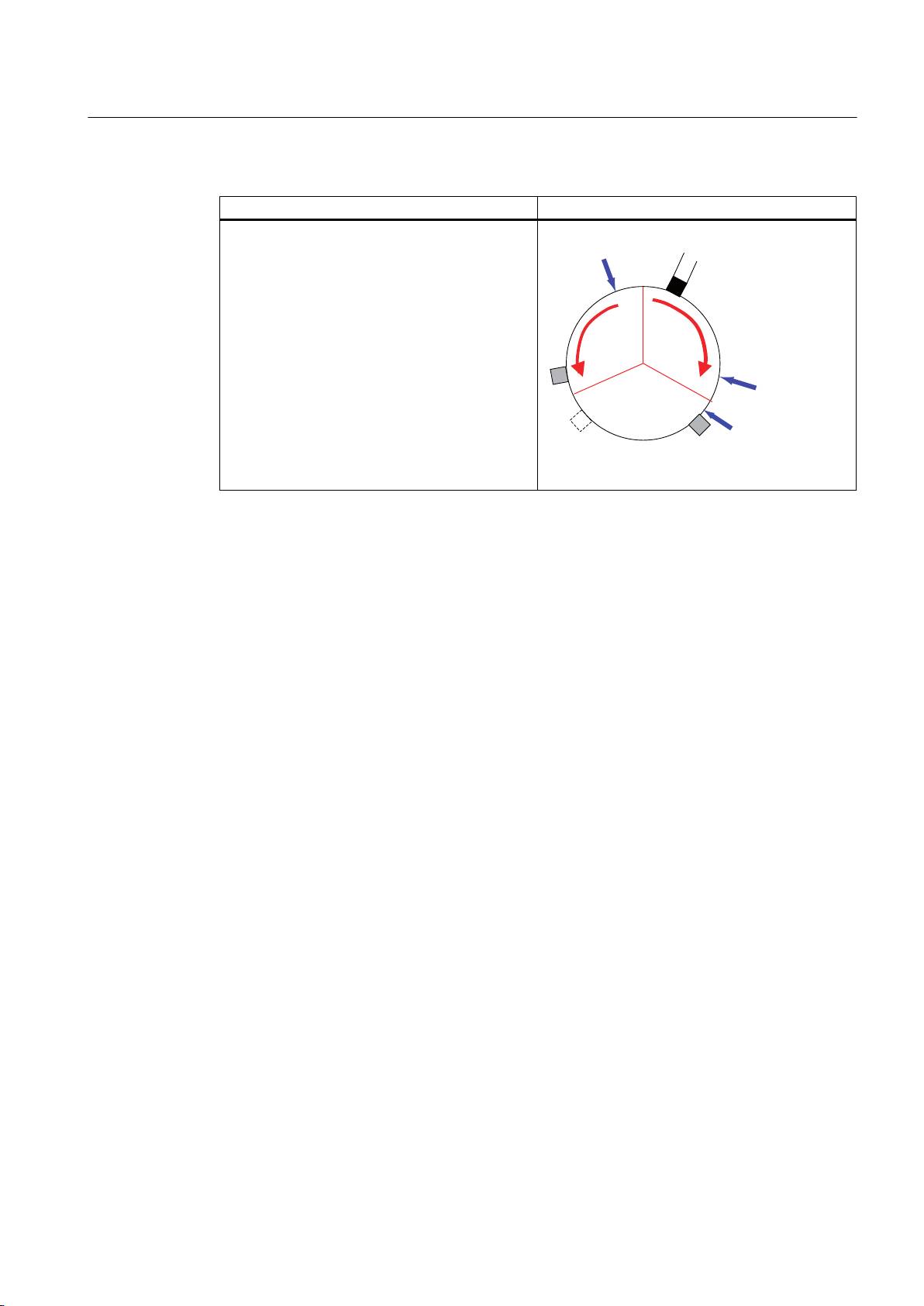
r
r
r
r
%
&
$b
%
(QDEOH$
2XWSXWFDP
FDP7\SH
(QDEOH%
(QDEOH&
Cam Track TO - Part II
4.2 TO Cam Track basics
Table 4-8 Example of a modulo axis with non-cyclic output and track length < modulo length
Cam track data/Explanation Representation
● Modulo length: 360°
● Track length: 0-120°
●
Output cam defaults: SOC=10°, EOC=20°
● Start mode: with next track cycle
4.2.6 Cam track operating behavior
Changes made
operation affect the cam track, which is active at that time. This section briefly describes the
most important changes.
An explanation of how you can determine the status of single output cams and cam tracks is
also provided.
The values of system variables are stored in the userdefault array. This array is transferred on
using _enableCamTrack to activate a cam track. These defaults are configured during cam
track configuration or other values can be written to them dynamically in the user program.
See also
Changing output cams on a cam track during runtime (Page 93)
Changing the track length during operation (Page 94)
Changing the axis configuration when a cam track is active (Page 95)
Calling up the status of cam tracks and single output cams (Page 95)
4.2.6.1 Changing output cams on a cam track during runtime
to the configuration and defaults of cam tracks or their associated axes during
Changing start and end positions of an output cam
The start and end positions of single output cams can only be changed by transferring the new
single positions to the userdefault array and using _enableCamTrack to activate the changed
array.
Output Cams and Measuring Inputs
Function Manual, 04/2014 93
Page 94
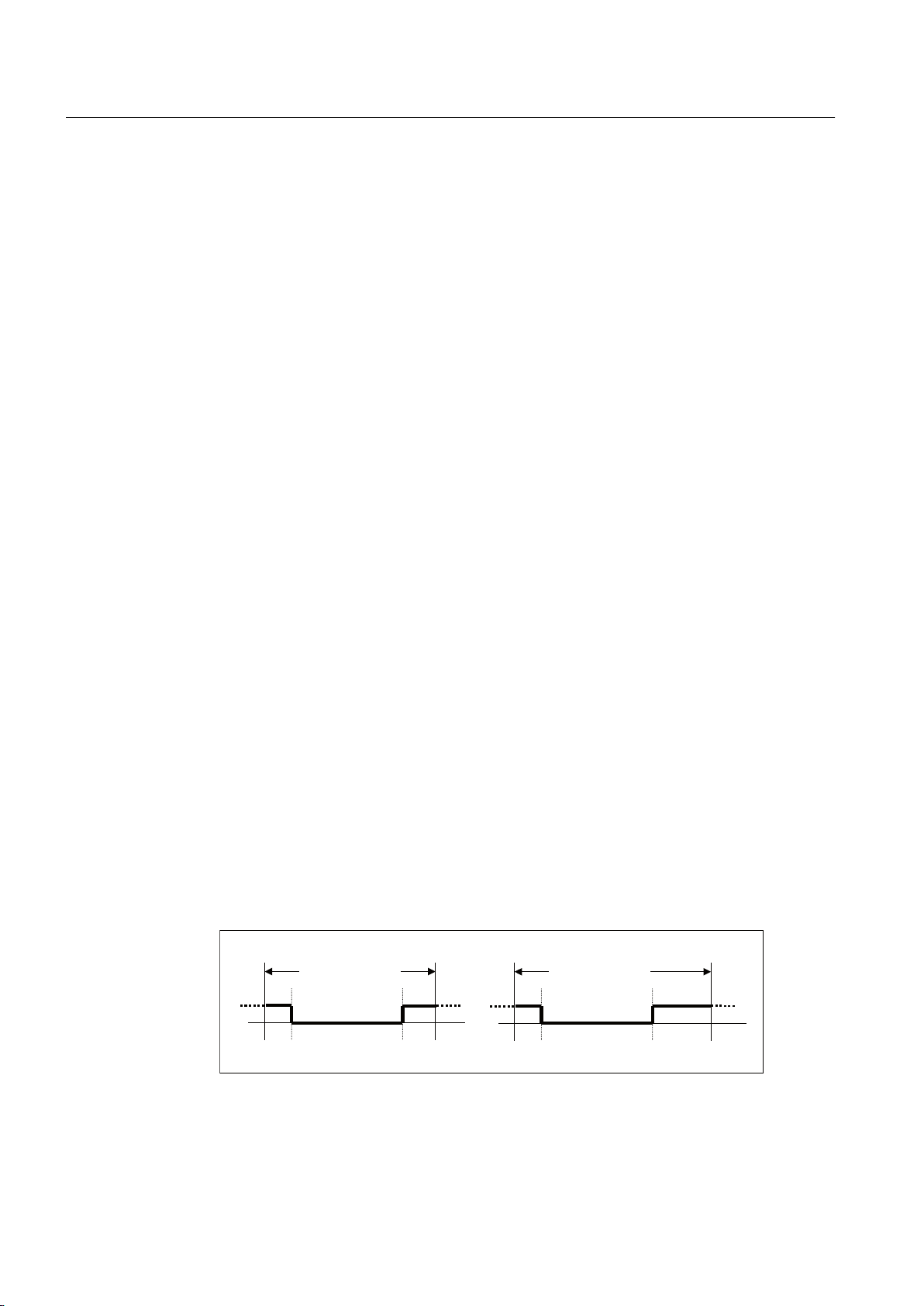
7UDFNOHQJWK
WRr
7UDFNOHQJWK
WRr
Cam Track TO - Part II
4.2 TO Cam Track basics
Validity of single output cams on a track
You can
define whether single output cams should be output or not. If existing output cams are to be
activated on an already active cam track, the relevant
userdefault.singleCamSettings.cam.cam[0-31].validity system variable can be set with the
value YES or NO, and the _enableCamTrack system function must be executed.
When parameterizing the cam track in SIMOTION SCOUT, validity can be set during
configuration in the Default window and the Output cam data tab (see the Defining cam track
defaults section).
Disabling or enabling valid output cams of a cam track without reactivation via
_enableCamTrack (as of V4.1)
Valid output cams of a cam track can be quickly disabled or enabled via the enableValidCam
system variable without reactivation of the cam track via _enableCamTrack.
Default setting of the enableValidCam system variable is 0xFFFFFFFF, i.e. all valid output
cams are enabled. By setting the bit of the relevant output cam, e.g. Bit_0 for output cam 0,
the valid output cam is enabled with 1 and disabled with 0 (e.g. only output cam 0 is disabled
with 0x FFFFFFFE).
Properties of enableValidCam:
define whether single output cams on a track are valid or invalid. This enables you to
● Value of enableValidCam is retained with reactivation by _enableCamTrack
● During system ramp-up or with _resetCamtTrack, enableValidCam is set to the default
setting 0xFFFFFFFF.
● Invalid output cams cannot be enabled via enableValidCam.
● System variable takes effect immediately without activation of the cam track.
4.2.6.2 Changing the track length during operation
The userdefault.camTrackLength system variable can be used to change the track length of
an active cam track during operation. Changes to a track length do not become effective until
the cam track is reactivated (_enableCamTrack). The track length of the cam track that is
already active remains unchanged unless it is overridden by the changed cam track.
Example of a changed track length
● 360° track length is changed to 400° and the new track is activated.
● Output cam defaults: SOC=310°, EOC=30°
Figure 4-20 Changed track length with an effect on switching states
Output Cams and Measuring Inputs
94 Function Manual, 04/2014
Page 95

4.2.6.3 Changing the axis configuration when a cam track is active
Changing the axis configuration for an assigned, active cam track affects cam track
behavior.
Cam Track TO - Part II
4.2 TO Cam Track basics
Changing modulo length
Changing the modulo length of an axis does not affect the definition or behavior of a cam track
when it is enabled.
If the modulo length of an axis is changed, the conversion of the cam track on that axis is not
automatically adjusted. If necessary, when changing the modulo length, you must deactivate
the active cam track and activate it again, so that the axis can be mapped according to the
new modulo length.
Output-cam output is aborted if the modulo length on an axis is changed and the axis is
restarted.
Redefine axis
If the axis position is changed during operation, e.g. with _redefinePosition, the cam track is
aborted and restarted. The change is interpreted as a skip in the modulo range. The cam track
is mapped onto the new modulo range of the axis.
4.2.6.4 Calling up the status of cam tracks and single output cams
You can detect the status of single output cams and cam tracks at any time via system
variables, and use the status in the user program.
Table 4-9 Status and position of cam tracks and single output cams
System variable Meaning Description
control Functional status of Cam
Track TO
state Output status The variable displays if cam track output is in an ON or OFF state.
singleCamState Status of single output cam The singleCamState
camTrackPosition Position of the cam track The camTrackPosition system
The variable displays the state of the cam track. For example, it can
be active, inactive or waiting for the next cam track cycle.
system
single output cams. The variable consists of a 32-bit array, in which
the lowest bit (bit0) represents output cam 0.
position of a cam track operation within a cam track cycle.
The cam track position is required, because the actual track position
of a cam track cannot be determined by means of the axis position of
a modulo axis (as, for example, the track length could be longer than
the modulo range of the axis).
The detected value always lies between the start (always "0") and end
(defined by the cam track length) of the track.
variable is used to read out the status of
variable is used to read out the actual
4.2.7 Inverting a cam track
If the
application requires, you can invert the cam track's activation level. The Cam Track TO
retains its positive logic. The cam track switches at level 1 or high.
Output Cams and Measuring Inputs
Function Manual, 04/2014 95
Page 96
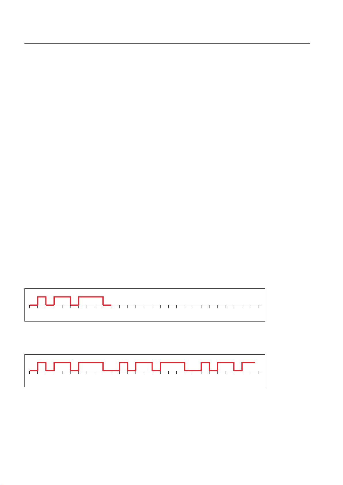
Cam Track TO - Part II
4.2 TO Cam Track basics
You can set the inversion via the OctTechnologicalCfg.invertOutput configuration
or in the Configuration window of the cam track. The TO must be restarted in order for a change
to be made.
4.2.8 Effect of cam track parameters on mapping
This chapter uses examples to explain the effect of configuration changes on cam track
mapping onto an axis.
See also
Basic mapping of a simple cam track (Page 96)
Advanced mappings with shifted output cam positions (Page 97)
4.2.8.1 Basic mapping of a simple cam track
One cam track with the following data is given.
● Three position-based cams (10-20; 30-50; 60-90)
data element
● Activation mode: Non-cyclical cam track activation
● Start mode and stop mode: Effective immediately
● Track length: 100
● All other user-default variables are the default setting unless another setting is mentioned
explicitly.
Display of given cam track with modified axis reference position, activation mode, and track
length
● Activation mode: Cyclic
● Activation mode: Cyclic
Output Cams and Measuring Inputs
96 Function Manual, 04/2014
Page 97
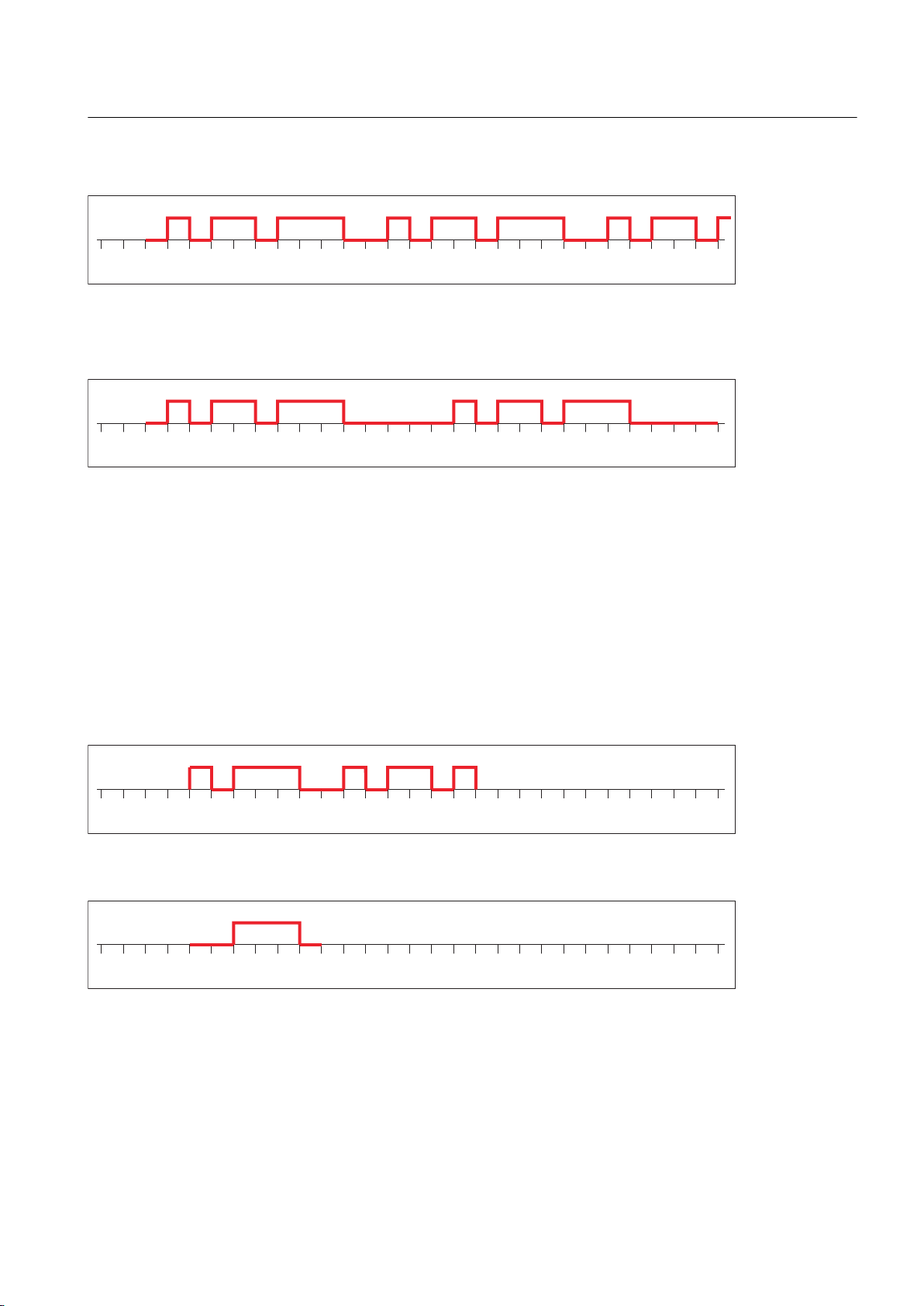
Cam Track TO - Part II
4.2 TO Cam Track basics
● Axis reference position: 20
● Activation mode: Cyclic
● Axis reference position: 20
Track length: 130
●
The following applies:
●
A change of axis reference position causes a change in the cyclic and non-cyclic mode.
The cam track is offset once.
A track length change only affects the cyclic mode and causes an offset in the cam track
●
cycle.
Display of given cam track with modified start/stop mode
● Start mode: Effective immediately
● Position of axis on which _enableCamTrack occurs: 40
● Position at which _disableCamTrack occurs: 170
● Activation mode: Cyclic
● Start mode: Immediate for inactive output cam track output
● Position of axis on which _enableCamTrack occurs: 40
4.2.8.2 Advanced mappings with shifted output cam positions
The following chapter presents examples of a cam track with shifted single cams, i.e. when
they are
outside the track length.
Output Cams and Measuring Inputs
Function Manual, 04/2014 97
mapped onto the axis, single cams are shifted to another position if they are defined
Page 98
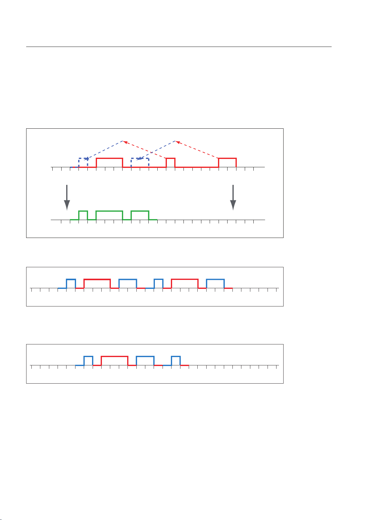
100
0
50
150
200
100
0 50
150
200
Mapping Mapping
Single output cams of the cam track are mapped onto the track
length and the position is recalculated. A new output cam track
results.
Cam Track TO - Part II
4.2 TO Cam Track basics
One cam track with the following data is given.
● Three position-based cams (30-60; 110-120; 170-190)
●
Track length: 100
● Axis reference position: 0
● All other user-default variables are the default setting unless another setting is mentioned
explicitly.
Display of given cam track with modified activation mode and axis reference position
● Activation mode: Cyclic
● Mode: Cyclic
● Axis reference position: 20
● Position at which _disableCamTrack occurs: 150
Output Cams and Measuring Inputs
98 Function Manual, 04/2014
Page 99

4.3 Configuring the TO Cam Track
This chapter describes typical operations used when working with the Cam Track technology
object.
See also
Inserting cam tracks (Page 99)
Parameterizing the Cam Track technology object (Page 100)
Using expert list for cam tracks (Page 100)
Configuring a cam track (Page 101)
Defining cam track defaults (Page 105)
Determining derivative-action times for cam tracks (dead time compensation) (Page 116)
Using HW enable for cam tracks (Page 118)
Cam Track TO - Part II
4.3 Configuring the TO Cam Track
4.3.1 Inserting cam tracks
Note
Before you
insert a cam track, the axis or external encoder to which the cam track is assigned
has to be created.
If the output cam is to be output to a TM15/TM17 High Feature module, the module must be
inserted and configured before the cam track configuration.
To insert a cam track:
1. In the project navigator, highlight the OUTPUT CAMS
external encoder.
2. Select Insert > Technology object > Cam track or double-click Insert cam track in the project
navigator under the axis or external encoder in the OUTPUT CAMS folder. The Insert cam
track window appears.
3. Enter a name for the cam track. You can also enter a comment.
Names must be unique throughout the project. For this reason, all the existing output cam
tracks are displayed under Available cam tracks.
4. Click OK to confirm. In the working area, the window for the configuration is displayed and
the created cam track TO is shown in the project navigator.
folder under the relevant axis or
Output Cams and Measuring Inputs
Function Manual, 04/2014 99
Page 100

Cam Track TO - Part II
4.3 Configuring the TO Cam Track
4.3.2 Parameterizing the Cam Track technology object
General information about configuration data and system variables
Two data classes are distinguished when parameterizing a TO.
Configuration data defines the principal functionality of a TO. They are set within the object
configuration framework with the SCOUT engineering system and are not normally changed
during runtime.
System variables provide status data of the TO for the user program and a parameterization
interface on the TO. System variables can be changed during runtime.
Note
You will find more information on technology objects in the
Functions
functional description.
SIMOTION Runtime Basic
To parameterize a cam track
1. In the project navigator under the OUTPUT CAMS
folder, find the cam track technology
object (TO) that you want to parameterize. Double-click the cam track TO to display the
associated objects.
2. Double-click Configuration or Default in the project navigator. The window appears on the
workspace.
– Configuration (see chapter Configuring a cam track):
Define the values for the configuration data of the cam track here. This includes, for
example, output cam type.
– Default (see chapter Defining cam track defaults):
Define the cam track defaults of the system variables here. This can include, for
example, cam track and output cam data.
3. Changing configuration data and defaults
4. Click Close to accept the changes.
5. Repeat steps 2 to 4 for all objects in which you want to change the configuration data and
defaults.
4.3.3 Using expert list for cam tracks
Parameters required for standard SIMOTION applications (configuration data and system
variables) are parameterized in the Cam Track TO directly by means of screen forms or are
defined automatically.
It may be necessary to change automatically-defined parameters for special SIMOTION
Output Cams and Measuring Inputs
100 Function Manual, 04/2014
 Loading...