

Page 1
Page 2

Page 3
Low-voltage motors
___________________
___________________
___________________
___________________
___________________
___________________
___________________
___________________
___________________
___________________
___________________
___________________
___________________
SIMOTICS GP, SD, DP, XP
Low-Voltage Motors
Low-voltage motors
Operating Instructions
05/2014
5 610 00000 02 000
Introduction
1
Safety information
2
Description
3
Preparing for use
4
Assembly
5
Electrical connection
6
Commissioning
7
Operation
8
Maintenance
9
Spare parts
10
Disposal
11
Appendix
A
Technical data and drawings
B
Page 4
Siemens AG
Industry Sector
Postfach 48 48
90026 NÜRNBERG
GERMANY
Order number: 5 610 00000 02 000
Ⓟ
Copyright © Siemens AG 2008 - 2014.
All rights reserved
Legal information
Warning notice system
DANGER
indicates that death or severe personal injury will result if proper precautions are not taken.
WARNING
indicates that death or severe personal injury may result if proper precautions are not taken.
CAUTION
indicates that minor personal injury can result if proper precautions are not taken.
NOTICE
indicates that property damage can result if proper precautions are not taken.
Qualified Personnel
personnel qualified
Proper use of Siemens products
WARNING
Siemens products may only be used for the applications described in the catalog and in the relevant technical
maintenance are required to ensure that the products operate safely and without any problems. The permissible
ambient conditions must be complied with. The information in the relevant documentation must be observed.
Trademarks
Disclaimer of Liability
This manual contains notices you have to observe in order to ensure your personal safety, as well as to prevent
damage to property. The notices referring to your personal safety are highlighted in the manual by a safety alert
symbol, notices referring only to property damage have no safety alert symbol. These notices shown below are
graded according to the degree of danger.
If more than one degree of danger is present, the warning notice representing the highest degree of danger will
be used. A notice warning of injury to persons with a safety alert symbol may also include a warning relating to
property damage.
The product/system described in this documentation may be operated only by
task in accordance with the relevant documentation, in particular its warning notices and safety instructions.
Qualified personnel are those who, based on their training and experience, are capable of identifying risks and
avoiding potential hazards when working with these products/systems.
for the specific
Note the following:
documentation. If products and components from other manufacturers are used, these must be recommended
or approved by Siemens. Proper transport, storage, installation, assembly, commissioning, operation and
All names identified by ® are registered trademarks of Siemens AG. The remaining trademarks in this publication
may be trademarks whose use by third parties for their own purposes could violate the rights of the owner.
We have reviewed the contents of this publication to ensure consistency with the hardware and software
described. Since variance cannot be precluded entirely, we cannot guarantee full consistency. However, the
information in this publication is reviewed regularly and any necessary corrections are included in subsequent
editions.
05/2014 Subject to change
Page 5

Table of contents
1 Introduction ............................................................................................................................................. 9
2 Safety information ................................................................................................................................. 11
3 Description ............................................................................................................................................ 15
4 Preparing for use .................................................................................................................................. 27
5 Assembly .............................................................................................................................................. 31
1.1 About these instructions ................................................................................................................. 9
1.2 Information for the reader .............................................................................................................. 9
2.1 Information for those responsible for the plant or system ............................................................ 11
2.2 The five safety rules ..................................................................................................................... 11
2.3 Qualified personnel ...................................................................................................................... 12
2.4 The safe use of electrical machines............................................................................................. 12
2.5 Safety instructions: Explosion-proof machines ............................................................................ 13
2.6 Special designs and construction versions .................................................................................. 13
2.7 Special conditions for explosion-proof machines ......................................................................... 13
3.1 Area of application ....................................................................................................................... 15
3.1.1 CE marking .................................................................................................................................. 15
3.2 Rating plates ................................................................................................................................ 16
3.3 Installation .................................................................................................................................... 17
3.3.1 Machine design ............................................................................................................................ 17
3.3.2 Regulations .................................................................................................................................. 18
3.3.3 Cooling and ventilation ................................................................................................................. 19
3.3.3.1 General ........................................................................................................................................ 19
3.3.3.2 Machines with a fan ..................................................................................................................... 19
3.3.3.3 Machines without a fan (optional) ................................................................................................ 20
3.3.4 Bearings ....................................................................................................................................... 21
3.3.5 Balancing ..................................................................................................................................... 21
3.3.6 Types of construction/method of installation ................................................................................ 22
3.3.7 Degree of protection .................................................................................................................... 24
3.3.8 Optional built-on and built-in accessories .................................................................................... 25
4.1 Delivery ........................................................................................................................................ 27
4.2 Transport ...................................................................................................................................... 27
4.3 Storage ......................................................................................................................................... 28
4.4 Electromagnetic compatibility ...................................................................................................... 29
5.1 Installation .................................................................................................................................... 31
5.1.1 Safety instructions ........................................................................................................................ 31
5.1.2 Safety instructions: Explosion-proof machines ............................................................................ 31
5.1.3 Machine installation ..................................................................................................................... 32
5.1.4 Cooling ......................................................................................................................................... 33
5.1.4.1 Ventilation .................................................................................................................................... 33
5.1.5 Machines with type of construction IM B15, IM B9, IM V8 and IM V9 ......................................... 34
Low-voltage motors
Operating Instructions, 05/2014, 5 610 00000 02 000
5
Page 6

Table of contents
6 Electrical connection ............................................................................................................................. 39
7 Commissioning ..................................................................................................................................... 67
5.1.6 Balancing..................................................................................................................................... 35
5.1.6.1 Mounting and withdrawing output transmission elements .......................................................... 36
5.1.7 Noise emission ............................................................................................................................ 37
5.2 Alignment and fastening .............................................................................................................. 37
5.2.1 Flatness of supporting surfaces .................................................................................................. 38
5.2.2 Machine frame mounting feet (special design) ........................................................................... 38
6.1 Connecting the machine ............................................................................................................. 39
6.1.1 General ........................................................................................................................................ 39
6.1.2 Terminal designations ................................................................................................................. 41
6.1.3 Direction of rotation ..................................................................................................................... 41
6.1.4 Connection with/without cable lugs ............................................................................................. 41
6.1.5 Connection with cable lug for explosion-protected machines ..................................................... 42
6.1.6 Connecting protruding cables ..................................................................................................... 42
6.1.7 Cable glands ............................................................................................................................... 42
6.1.7.1 Mounting position of sheet metal nuts in screw-type connections .............................................. 43
6.1.8 Terminal box ............................................................................................................................... 44
6.1.8.1 General ........................................................................................................................................ 44
6.1.8.2 Versions ...................................................................................................................................... 45
6.1.8.3 Protruding connection cables ...................................................................................................... 47
6.1.8.4 Connecting the temperature sensor/anti-condensation heater ................................................... 48
6.1.8.5 Cable entry .................................................................................................................................. 50
6.1.8.6 Thread sizes in terminal box ....................................................................................................... 51
6.2 Tightening torques ...................................................................................................................... 53
6.2.1 Electrical connections - Termincal board connections ................................................................ 53
6.2.2 Cable glands ............................................................................................................................... 54
6.2.3 Terminal boxes, end shields, grounding conductors, sheet metal fan covers ............................ 54
6.3 Conductor connection ................................................................................................................. 55
6.3.1 General information on conductor connection ............................................................................ 55
6.3.2 Type of conductor connection ..................................................................................................... 56
6.4 Connecting the grounding conductor ..........................................................................................
59
6.4.1 General information on connecting the grounding conductor ..................................................... 59
6.4.2 Grounding connection type ......................................................................................................... 60
6.4.3 Minimum surface area of grounding conductor........................................................................... 61
6.4.4 Size of grounding conductor screw ............................................................................................. 62
6.5 Final measures ............................................................................................................................ 62
6.6 Connecting optional mounted components ................................................................................. 63
6.6.1 External fan, incremental encoder, brake ................................................................................... 63
6.6.1.1 Mounting a brake ........................................................................................................................ 63
6.6.1.2 Mounted external fan .................................................................................................................. 63
6.7 Connecting converters ................................................................................................................ 64
7.1 Insulation resistance ................................................................................................................... 67
7.1.1 Testing the insulation resistance ................................................................................................. 67
7.2 Measures before start-up ............................................................................................................ 69
7.3 Switching on ................................................................................................................................ 71
Low-voltage motors
6 Operating Instructions, 05/2014, 5 610 00000 02 000
Page 7

Table of contents
8 Operation .............................................................................................................................................. 73
9 Maintenance ......................................................................................................................................... 87
8.1 Safety instructions ........................................................................................................................ 73
8.1.1 Safety instructions during operation............................................................................................. 73
8.1.2 Safety information for explosion-protected machines in operation .............................................. 75
8.1.3 Safety instructions for cleaning .................................................................................................... 76
8.1.4 Machines with textile fan covers .................................................................................................. 76
8.2 Stoppages .................................................................................................................................... 76
8.3 Fault tables ................................................................................................................................... 78
8.4 Deactivating ................................................................................................................................. 80
8.5 Class ............................................................................................................................................ 80
8.5.1 Zone 1 with type of protection Ex de IIC Gb (flameproof enclosure "d" for the machine
and increased safety "e" for the terminal box) ............................................................................. 80
8.5.2 Zone 1 with Ex e IIC Gb type of protection (increased safety "e") ............................................... 81
8.5.3 Zone 1 with Ex e IIB Gb type of protection (increased safety "e") ............................................... 82
8.5.4 Zone 2 with type of protection Ex nA IIC Gc, non sparking ......................................................... 83
8.5.5 Zone 2 with type of protection Ex nA IIB Gc, non sparking ......................................................... 84
8.5.6 Zone 21 ........................................................................................................................................ 85
8.5.7 Zone 22 ........................................................................................................................................ 86
9.1 Preparation and notes .................................................................................................................. 87
9.1.1 North American market ................................................................................................................ 88
9.1.2 Customs union Eurasia ................................................................................................................ 88
9.1.3 Touch up any damaged paintwork ............................................................................................... 90
9.1.4 Repainting .................................................................................................................................... 90
9.2 Inspection ..................................................................................................................................... 91
9.2.1 General inspection specifications ................................................................................................ 91
9.2.2 Optional built-on accessories ....................................................................................................... 91
9.2.3 Initial inspection............................................................................................................................ 91
9.2.4 Main inspection ............................................................................................................................ 92
9.3 Maintenance ................................................................................................................................. 93
9.3.1 Maintenance intervals .................................................................................................................. 93
9.3.2 Regreasing (optional) ................................................................................................................... 94
9.3.3 Cleaning ....................................................................................................................................... 94
9.3.4 Drain condensate ......................................................................................................................... 95
9.4 Corrective maintenance ............................................................................................................... 96
9.4.1 Instructions for repair ................................................................................................................... 96
9.4.2 Storage ......................................................................................................................................... 96
9.4.2.1 Changing bearings ....................................................................................................................... 97
9.4.2.2 Replacing bearings in explosion-proof machines ........................................................................ 98
9.4.3 Dismantling .................................................................................................................................. 98
9.4.3.1 Bearing bushes ............................................................................................................................ 99
9.4.3.2 Links ............................................................................................................................................. 99
9.4.4 Assembly ...................................................................................................................................... 99
9.4.4.1 Assemly ........................................................................................................................................ 99
9.4.4.2 Fitting the bearing cartridges ....................................................................................................... 99
9.4.4.3 Fitting bearings........................................................................................................................... 100
9.4.4.4 Mounting fans............................................................................................................................. 100
Low-voltage motors
Operating Instructions, 05/2014, 5 610 00000 02 000
7
Page 8

Table of contents
10 Spare parts .......................................................................................................................................... 105
11 Disposal ............................................................................................................................................... 113
A Appendix ............................................................................................................................................. 115
B Technical data and drawings ................................................................................................................ 117
Glossary .............................................................................................................................................. 133
Index ................................................................................................................................................... 135
9.4.4.5 Mounting the fan cover .............................................................................................................. 101
9.4.4.6 Canopy; mounting a rotary pulse encoder under the canopy ................................................... 101
9.4.4.7 Reassembly: Miscellaneous information ................................................................................... 101
9.4.5 Screw lock washers .................................................................................................................. 102
9.4.6 Electrical connections - Termincal board connections .............................................................. 102
9.4.7 Cable glands ............................................................................................................................. 102
9.4.8 Terminal boxes, end shields, grounding conductors, sheet metal fan covers .......................... 103
9.4.9 Optional add-on units ................................................................................................................ 104
10.1 Parts order................................................................................................................................. 105
10.2 Parts groups definition .............................................................................................................. 105
10.3 Ordering example ...................................................................................................................... 106
10.4 Machine parts ............................................................................................................................ 107
10.5 Standardized parts .................................................................................................................... 110
11.1 Introduction................................................................................................................................ 113
11.2 Preparing for disassembly ......................................................................................................... 113
11.3 Dismantling the machine ........................................................................................................... 113
11.4 Disposal of components ............................................................................................................ 114
A.1 SIEMENS Service Center ......................................................................................................... 115
A.2 Languages of operating instructions available in the Internet ................................................... 115
A.3 Further documents .................................................................................................................... 116
B.1 Exploded drawings .................................................................................................................... 117
B.1.1 1LA,1LP,1MA,1MF,1PP6/7/9 FS 56 ... 90L .............................................................................. 117
B.1.2 1LA,1LP,1MA,1MF,1PP6/7/9 FS 100 ... 160 ............................................................................ 118
B.1.3 1LA5180 ... 225 ......................................................................................................................... 119
B.1.4 1MA6180 ... 200 ........................................................................................................................ 120
B.1.5 Terminal boxes 1MA6180 ... 200 .............................................................................................. 121
B.1.6 1MJ6070 ... 200 ........................................................................................................................ 122
B.1.7 Terminal boxes 1MJ6070 ... 160 ............................................................................................... 123
B.1.8 Terminal boxes 1MJ6180 ... 200 (Ex e) .................................................................................... 124
B.1.9 Terminal boxes 1MJ6180 ... 200 (Ex d) .................................................................................... 125
B.1.10 1LE1/ 1MB1 BG 80 ... 160 aluminum ....................................................................................... 126
B.1.11 1LE1 / 1MB1 BG 100 ... 200 cast iron ...................................................................................... 127
B.1.12 1LE1 / 1MB1 BG 225 ... 315 cast iron ...................................................................................... 128
B.1.13 1LG4/6 FS 180 ... 315 ............................................................................................................... 129
B.1.14 Terminal box gk330, gt320, gk430, gt420 ................................................................................. 130
B.1.15 Terminal box gk431, gt421, gt520, gt540 ................................................................................. 131
B.1.16 Terminal box 1LG4/6 gt620, gt640, gt791 ................................................................................ 132
Low-voltage motors
8 Operating Instructions, 05/2014, 5 610 00000 02 000
Page 9

1
1.1
About these instructions
Text format features
Note
A Note is an important item of information about the product, handling of the produc
relevant section of the document. Notes provide you with help or further suggestions/ideas.
1.2
Information for the reader
Explanation of the icons
These instructions describe the machine and explain how to handle it, from initial delivery to
final disposal of the equipment. Keep these instructions for later use.
Read these operating instructions before you handle the machine and follow the instructions
to become familiar with its design and operating principles and thus ensure safe, problemfree machine operation and long service life.
If you have suggestions for improving the document, please contact the Service Center.
The warning notice system is explained on the rear of the inside front. Always follow the
safety instructions and notices in these instructions.
In addition to the safety-related warning notices which you must read, you will find the text in
these instructions is formatted in the following way:
1. Handling instructions are always formatted as a numbered list. Always perform the steps
in the order given.
● Lists are formatted as bulleted lists.
– Lists on the second level are hyphenated.
Note for 1LE1, 1MB1, 1PC1, 1PC3 machines
t or the
Note for 1LE1, 1PC1 and 1PC3 machines, frame sizes 80 and 90 with central terminal box
locking
Information about explosion-protected machines
Low-voltage motors
Operating Instructions, 05/2014, 5 610 00000 02 000
9
Page 10

Introduction
1.2 Information for the reader
Low-voltage motors
10 Operating Instructions, 05/2014, 5 610 00000 02 000
Page 11

2
2.1
Information for those responsible for the plant or system
Note
Use the services and support provided by the appropriate Service
installation
2.2
The five safety rules
Five safety rules
This electric machine has been designed and built in accordance with the specifications
contained in Directive 2006/95/EC ("Low-Voltage Directive") and is intended for use in
industrial plants. Please observe the country-specific regulations when using the electric
machine outside the European Community. Follow the local and industry-specific safety and
setup regulations.
The persons responsible for the plant must ensure the following:
● Planning and configuration work and all work carried out on and with the machine is only
to be done by qualified personnel.
● The operating instructions must always be available for all work.
● The technical data as well as the specifications relating to the permissible installation,
connection, ambient and operating conditions are taken into account at all times.
● The specific setup and safety regulations as well as regulations on the use of personal
protective equipment are observed.
Center for planning,
, commissioning, and servicing work.
You will find safety instructions in the individual sections of this document. Follow the safety
instructions for your own safety, to protect other people and to avoid damage to property.
Observe the following safety instructions for all activities on and with the machine.
For your personal safety and to prevent material damage when carrying out any work,
always observe the safety instructions and the following five safety rules, according to
EN 50110-1 "Dead working". Apply the five safety rules in the sequence stated before
starting work.
1. Disconnect completely.
Disconnect the auxiliary circuits, for example anti-condensation heating.
2. Secure against reconnection.
3. Verify absence of operating voltage.
4. Carry out earthing and short-short-circuiting.
5. Provide protection against adjacent live parts.
To energize the system, apply the measures in reverse order.
Low-voltage motors
Operating Instructions, 05/2014, 5 610 00000 02 000
11
Page 12
Safety information
2.3
Qualified personnel
2.4
The safe use of electrical machines
WARNING
High voltages
WARNING
Rotating parts
WARNING
Risk of burning
2.3 Qualified personnel
All work at the machine must be carried out by qualified personnel only. For the purpose of
this documentation, qualified personnel is taken to mean people who fulfill the following
requirements:
● Through appropriate training and experience, they are able to recognize and avoid risks
and potential dangers in their particular field of activity.
● They have been instructed to carry out work on the machine by the appropriate person
responsible.
Electrical machines contain live parts. Fatal or severe injuries and substantial material
damage can occur if the required covers are removed or if the machines are not handled,
operated, or maintained properly.
• Only remove covers in compliance with the applicable regulations.
• Operate the machines properly.
• Perform regular maintenance on the machine.
Electrical machines contain dangerous rotating parts. Fatal or severe injuries and
substantial material damage can occur if the required covers are removed or if the
machines are not handled, operated, or maintained properly.
• Only remove covers in compliance with the applicable regulations.
• Operate the machines properly.
• Perform regular maintenance on the machine.
• Secure free-standing shaft extensions.
Electrical machines have hot surfaces. Fatal or severe injuries and substantial material
damage can occur if the required covers are removed or if the machines are not handled,
operated, or maintained properly.
• Allow the machine to cool down before starting any work on it.
• Only remove covers in compliance with the applicable regulations.
• Operate the machines properly.
Low-voltage motors
12 Operating Instructions, 05/2014, 5 610 00000 02 000
Page 13
Safety information
2.5
Safety instructions: Explosion-proof machines
Note
The increased level of danger in hazardous areas demands that you pay particular attention
to the notes marked with
2.6
Special designs and construction versions
Note
Before carry out any work on the machine, determine the machine version.
If any deviations or uncertainties arise, contact the manufacturer specifying the type
designation and serial number (see rati
Siemens
2.7
Special conditions for explosion-proof machines
Flameproof enclosure "d"
Zone 21
2.5 Safety instructions: Explosion-proof machines
.
ng plate) or have the equipment repaired by a
Service Center.
Special conditions for the safe application of explosion-protected machines marked with X
(excerpt from the EC type-examination certificate, point 17)
Flameproof joints may only be repaired strictly in accordance with the manufacturer's design
specifications. Repair in accordance with the values in Tables 1 and 2 of EN / IEC 60079-1 is
not permitted.
● Do not operate the motors with excessively thick deposits of dust.
● When the motors are mounted with the free shaft end pointing upwards, prevent foreign
● For motors with a fixed connecting cable: The free end of the cable must be connected
bodies from dropping into the ventilation openings using an appropriate mechanical
design.
according to valid regulations for electrical installations.
Low-voltage motors
Operating Instructions, 05/2014, 5 610 00000 02 000
13
Page 14

Safety information
2.7 Special conditions for explosion-proof machines
Low-voltage motors
14 Operating Instructions, 05/2014, 5 610 00000 02 000
Page 15

3
3.1
Area of application
Overview
Intended use of the machines
Note
Machine directive
Low
with the current Machinery Directive. They must not be commis
verified that the end product complies with this directive (refer to EN 60204
3.1.1
CE marking
Note
Use of machines without CE identification
Machines without
Area (EEA). Do not use any machines without CE mark within of the EEA!
The three-phase machines of this series are used as industrial drives. They are designed for
a wide range of drive applications both for line operation as well as in conjunction with
frequency converters.
They are characterized by their high power density, extreme robustness, long service life
and outstanding reliability.
These machines are intended for industrial installations. They comply with the harmonized
standards of the series EN / IEC 60034 (VDE 0530). Their use in hazardous areas is
forbidden unless the marking on the rating plate expressly permits this operation. If
other/more wide-ranging demands (e.g. protection so that they cannot be touched by
children) are made in special cases – i.e. use in non-industrial installations – these conditions
must have been complied with in the plant or system itself when the motors are installed.
-voltage motors are components designed for installation in machines in accordance
sioned until it has been
-1).
marking are intended for operation outside the European Economic
Low-voltage motors
Operating Instructions, 05/2014, 5 610 00000 02 000
15
Page 16

Description
3.2
Rating plates
Rating plate
Data on the rating plate
Item
Description
Item
Description
General data
Electrical data
1
Type of machine
31
Electrical data
2
Machine type
32
-
YY.MM )
4
Standards
34
Winding connections
5
Additional details (optional)
35
Frequency [Hz]
6
Customer data (optional)
36
Rated power [kW]
7
Country of origin
37
Rated current [A]
8
Production location
38
Power factor [cosφ]
(optional)
10
Regulations (optional)
40
Efficiency class
Mechanical data
41
Efficiency
11
Frame size
42
Torque [Nm] (optional)
12
Type of construction
43
Rated power [hp] (optional)
13
Degree of protection
44
Service factor (optional)
14
Machine weight [kg]
45
Starting current ratio (optional)
15
Temperature class
46
Operating mode (optional)
16
Ambient temperature range (optional)
47
NEMA data (optional)
m)
18
Vibration severity grade
49
Company logo
19
Bearing sizes
20
Relubrication data/specifications (optional)
21
Brake data (optional)
3.2 Rating plates
The rating plate shows the identification data and the most important technical data. The
data on the rating plate and the contractual agreements define the limits of proper usage.
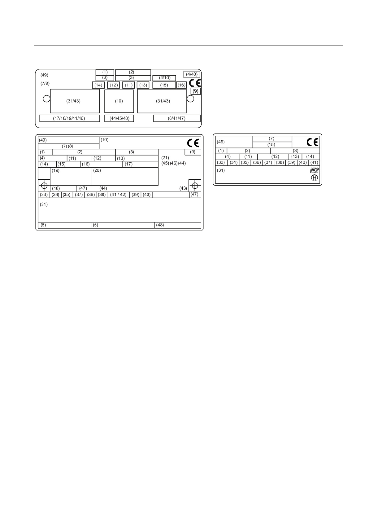
3 Serial number (incl. date of manufacture
9 Identification number of testing agency
33 Rated voltage [V]
39 Rated speed [rpm]
17 Installation altitude (only if higher than 1000
Low-voltage motors
16 Operating Instructions, 05/2014, 5 610 00000 02 000
48 Anti-condensation heating (optional)
Page 17
Description
3.3
Installation
3.3.1
Machine design
3.3 Installation
Figure 3-1 Examples of rating plates
Machines of this series are low-voltage three-phase asynchronous drives with a cylindrical
shaft end and featherkey way. They can be supplied as single-speed machines with different
efficiency classes or as pole changing machines for several speeds.
In the case of machines with feet (IM B3 type of construction), the feet are cast or bolted on.
It is possible to change the feet bolted on the housing of the machine, e.g. to change the
position of the terminal box; however, only have this performed by an authorized retrofit
partner.
With the appropriate post working, ensure that the feet mounting surfaces are again on one
plane and parallel to the machine shaft, and shim when required. Professionally touch up
damaged painted surfaces.
Low-voltage motors
Operating Instructions, 05/2014, 5 610 00000 02 000
17
Page 18
Description
3.3.2
Regulations
Standard motors
Feature
Standard
Dimensioning and operating behavior
EN / IEC 60034-1
EN / IEC 60034-2-3
Degree of protection
EN / IEC 60034-5
Cooling
EN / IEC 60034-6
Type of construction
EN / IEC 60034-7
Terminal designations and direction of rotation
EN / IEC 60034-8
Noise emission
EN / IEC 60034-9
Starting characteristics of rotating electrical machines
EN / IEC 60034-12
Vibration severity grades
EN / IEC 60034-14
Efficiency classification of three-phase squirrel-cage induction motors
EN / IEC 60034-30
IEC standard voltages
IEC 60038
Supplementary regulations for explosion-proof machines
Feature
Standard
Electrical equipment for hazardous gas atmospheres, Part 0: General requirements
EN / IEC 60079-0
Electrical equipment for hazardous gas atmospheres, Part 1: Flameproof enclosure "d"
EN / IEC 60079-1
Electrical equipment for hazardous gas atmospheres, Part 7: Increased safety "e"
EN / IEC 60079-7
endangered atmospheres (except underground excavation)
Electrical equipment for hazardous gas atmospheres, Part 15: Type of protection "n"
EN / IEC 60079-15
Electrical equipment for hazardous gas atmospheres, Part 19: Repairs and overhauls
EN / IEC 60079-19
Potentially explosive atmosphere - Part 31: Device dust explosion protection by enclosure "t"
EN / IEC 60079-31
maintenance of electrical systems in hazardous areas (except underground excavation)
protective systems intended for use in hazardous areas.
3.3 Installation
The regulations and standards used as basis to design and test this machine are stamped
on the rating plate. The machine design basically complies with the following standards:
Table 3- 1 Applicable general regulations
Procedure for determining the losses and the efficiency of rotating electrical machines and
inspections
Table 3- 2 Regulations applied for explosion-protected machines
EN / IEC 60034-2-1
EN / IEC 60034-2-2
Electrical equipment for hazardous gas atmospheres, Part 14: Electric installations for
Electrical equipment for use in the presence of combustible dust - Part 17: Inspection and
Directive on the approximation of the laws of the Member States concerning equipment and
Low-voltage motors
18 Operating Instructions, 05/2014, 5 610 00000 02 000
EN / IEC 60079-14
EN / IEC 60079-17
RL94/9/EC
Page 19
Description
3.3.3
Cooling and ventilation
3.3.3.1
General
3.3.3.2
Machines with a fan
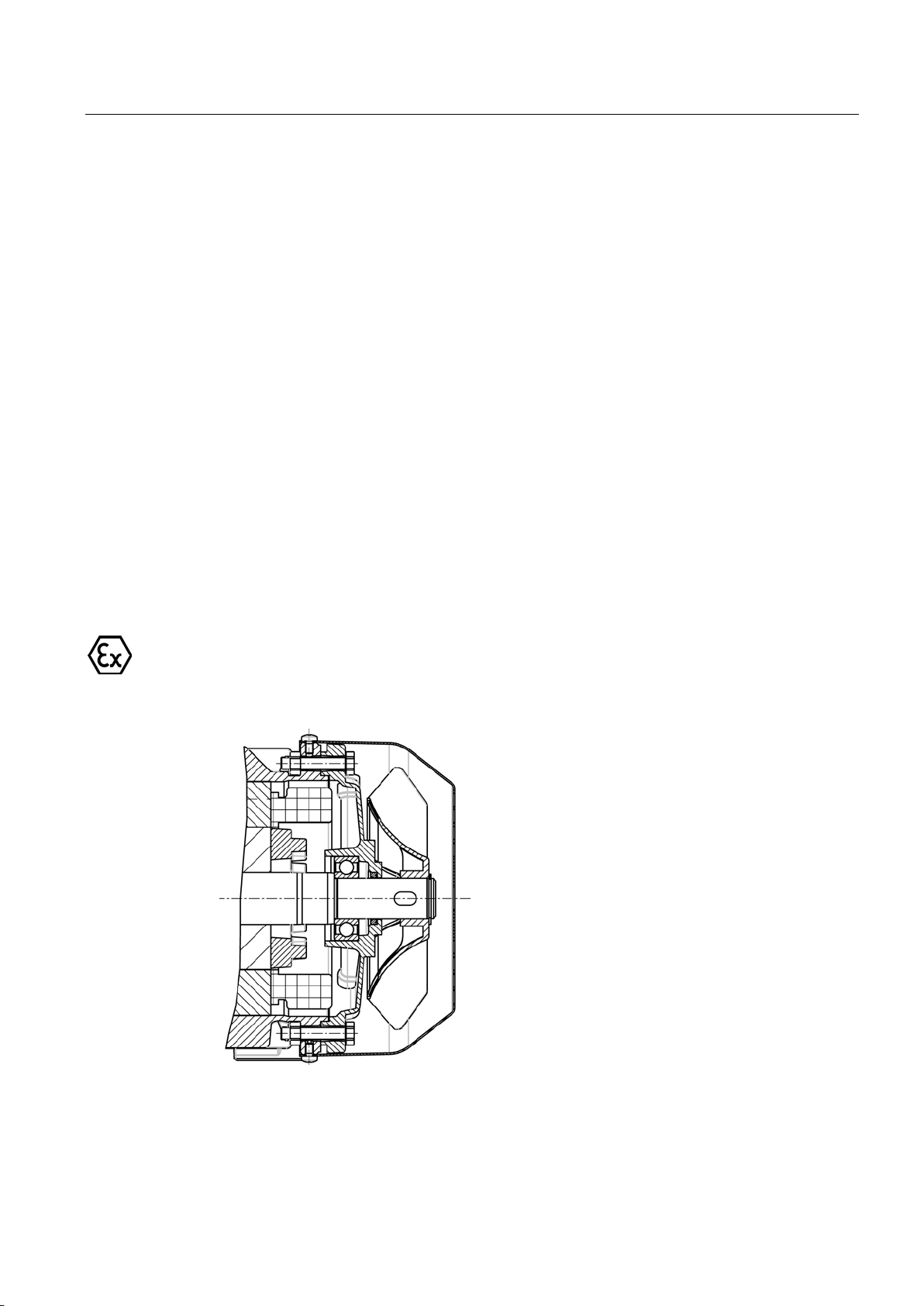
Self-ventilation (standard): Cooling IC 411 in accordance with EN / IEC 60034-6
Note explosion-protected machines
3.3 Installation
The machines of this series are three-phase asynchronous machines with a closed primary
(internal) cooling circuit and an open secondary cooling circuit (surface cooling). The surface
cooling varies depending on the version.
Located at the ND end of the stator housing is an air intake cowl that guides the external air
on its way to the motor. The external air is drawn in through openings in the air intake cowl
and flows axially across the outer cooling ribs of the motor frame. The fan wheel for the
external flow of cooling air is attached to the machine shaft.
The fan wheels are bidirectional.
Check the cooling effect below rated speed in the case of frequent switching or braking – or
if the speed is controlled continually below the rated speed.
Machines for use in Zone 21 and Zone 22 have a metal fan.
Low-voltage motors
Operating Instructions, 05/2014, 5 610 00000 02 000
19
Page 20
Description
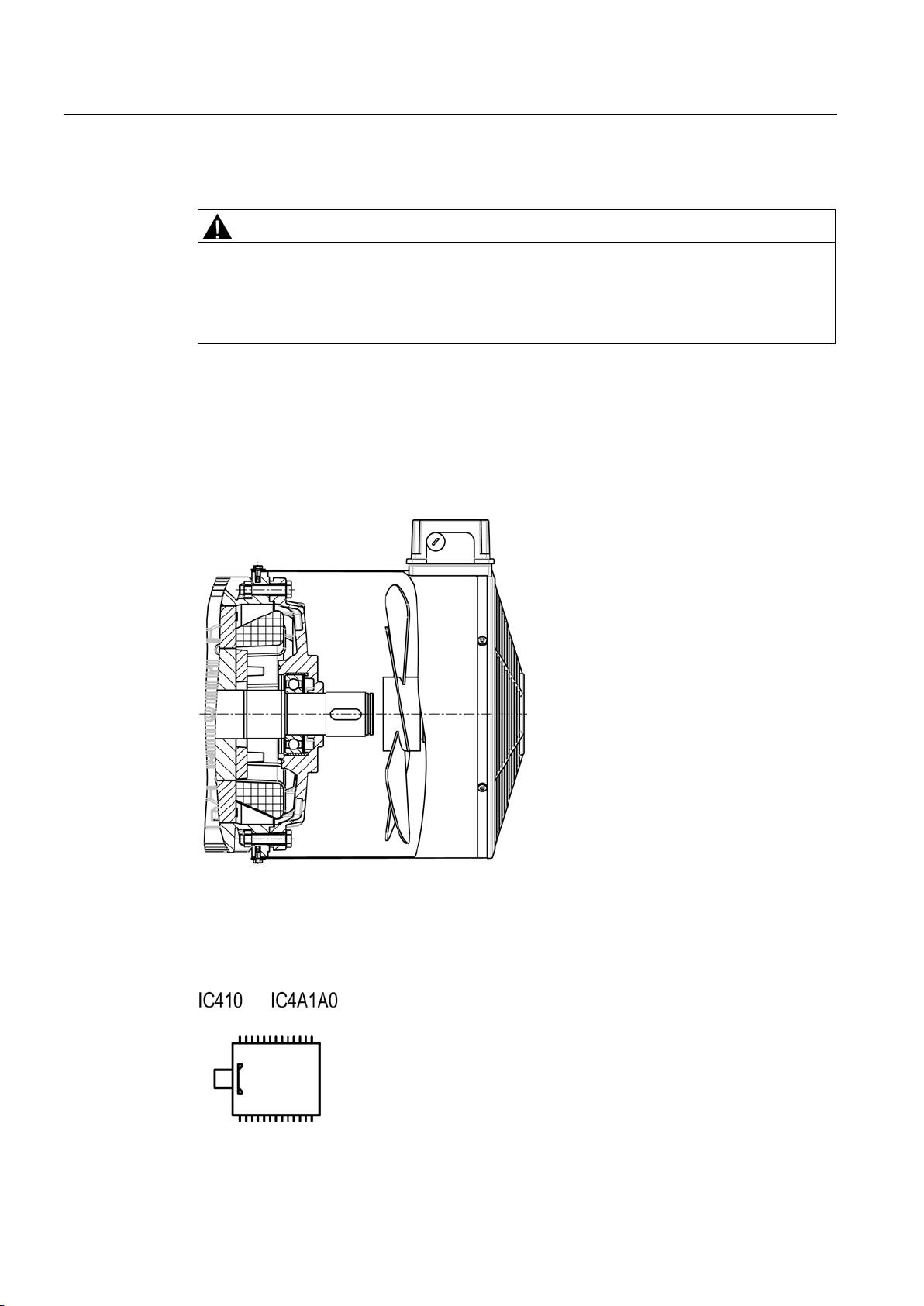
Forced ventilation (optional): Type of cooling IC 416 in accordance with EN / IEC 60034-6
WARNING
Risk of burning
3.3.3.3
Machines without a fan (optional)
Surface cooling by free convection: Cooling IC 410 in accordance with EN / IEC 60034-6
3.3 Installation
Operating the machine without external fan results in overheating. This may result in
personal injury and material damage.
Never commission the machine without an external fan.
Cooling that does not depend on the speed is achieved by means of a separately driven fan
wheel (forced ventilation). Forced ventilation does not depend on the operating state of the
machine.
The fan wheel for the external flow of cooling air is powered by an independent module and
is enclosed by the fan cover.
Low-voltage motors
20 Operating Instructions, 05/2014, 5 610 00000 02 000
Figure 3-2 IC410
Page 21
Description
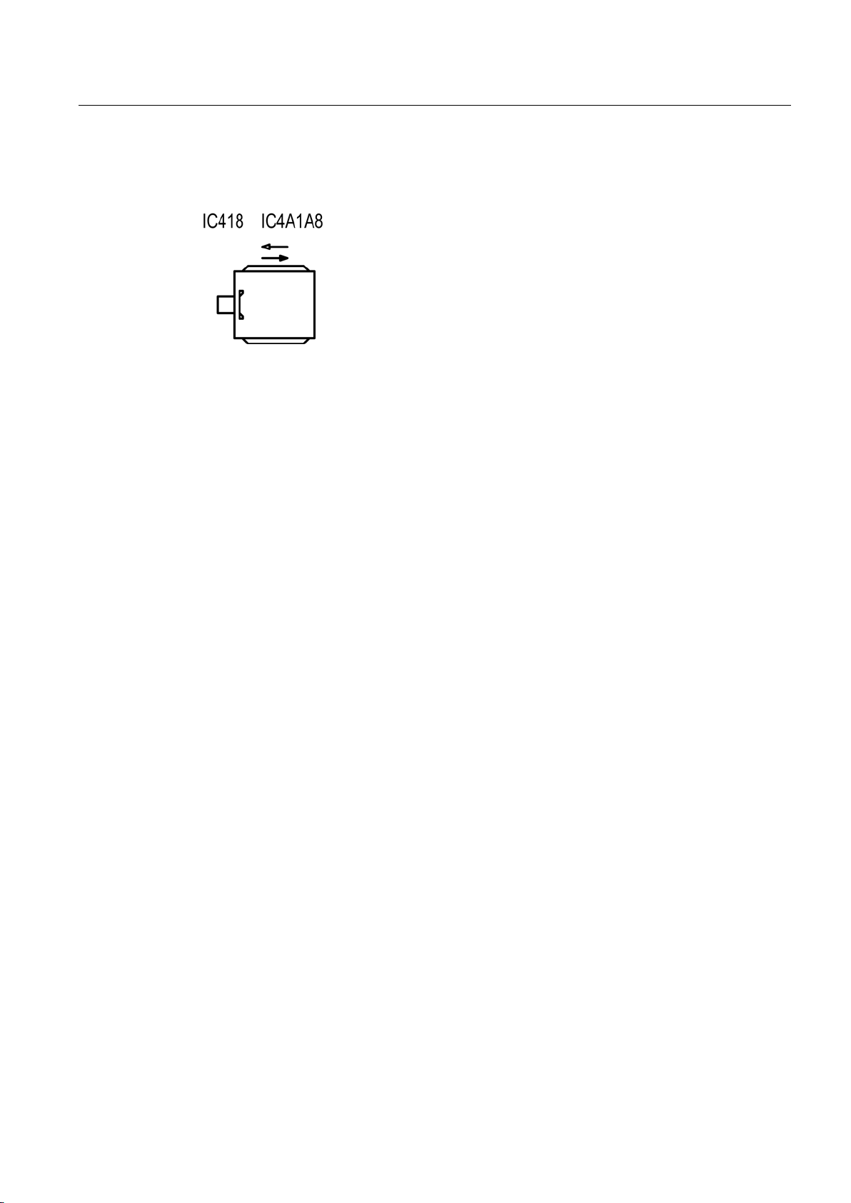
Surface cooling by relative movement of cooling air: Type of cooling IC 418 in accordance with
EN / IEC 60034-6
3.3.4
Bearings
3.3.5
Balancing
3.3 Installation
Figure 3-3 IC418
In order to support the machine shaft and maintain its position in the non-moving part of the
machine, only 2 rolling-contact bearings are used. One roller bearing performs the function
of a location bearing that transfers axial and radial forces from the rotating machine shaft to
the non-moving part of the machine. The second roller bearing is implemented as floating
and support bearing in order to allow thermal expansion inside the machine and transfer
radial forces.
The nominal (calculated) useful life of the bearings according to ISO 281 is at least 20,000
hours with utilization of the permissible radial/axial forces. However, the achievable useful
life of the bearings can be significantly longer in the case of lower forces (e.g. operation with
self-aligning couplings).
Avoid rigid couplings.
Roller bearings with permanent lubrication are maintenance-free. For bearings that can be
relubricated, observe the data on the rating plate or lubricant plate.
As standard, the motor is balanced dynamically with a half featherkey (code "H") in
accordance with ISO 8821.
The balance quality corresponds to vibration level "A". Vibration level "B" is optional or
possible on request.
Low-voltage motors
Operating Instructions, 05/2014, 5 610 00000 02 000
21
Page 22
Description
3.3.6
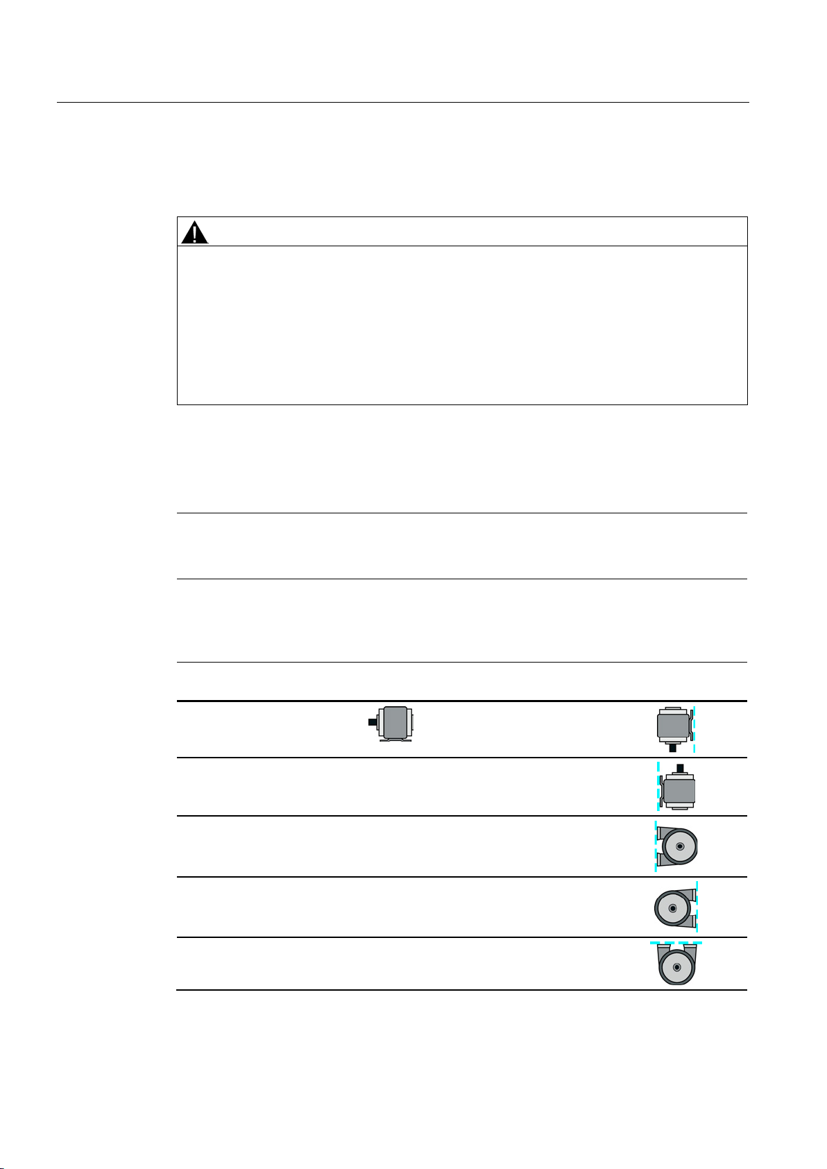
Types of construction/method of installation
WARNING
Damage caused by small parts falling in
Further possible fields of application
Note
When lifting the machines for t
basic construction type.
Basic type of
construction code
Diagram
Other methods of
installation
Diagram
3.3 Installation
Material damage and injury can occur if the fan is destroyed and therefore the motor
overheats.
• For types of construction with a shaft extension facing downwards, a suitable cover
must be fitted to prevent small parts from falling into the fan cover (see also standard
IEC / EN 60079-0).
• Prevent the cooling airflow from being reduced as a result of covers that might be in
place.
The type of construction of the machine is stated on the rating plate.
ransport, only lift them in a position that corresponds to their
Table 3- 3 Type of construction
IM B3 (IM 1001)
IM V6 (IM 1031)
IM B6 (IM 1051)
IM B7 (IM 1061)
IM B8 (IM 1071)
IM V5 (IM 1011)
Low-voltage motors
22 Operating Instructions, 05/2014, 5 610 00000 02 000
Page 23
Description
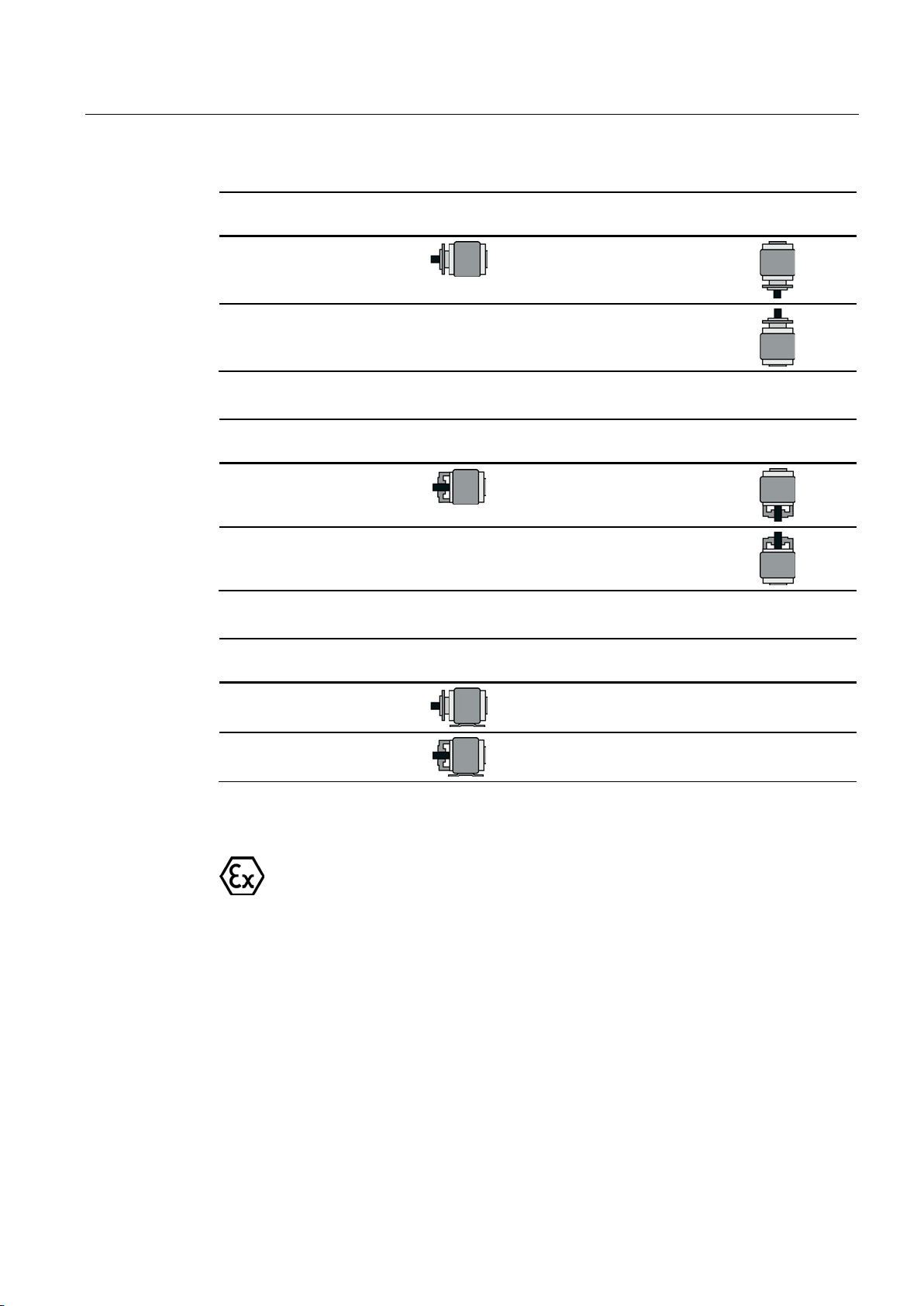
Basic type of
construction code
Diagram
Other methods of
installation
Diagram
Basic type of
construction code
Diagram
Other methods of
installation
Diagram
Basic type of
construction code
Diagram
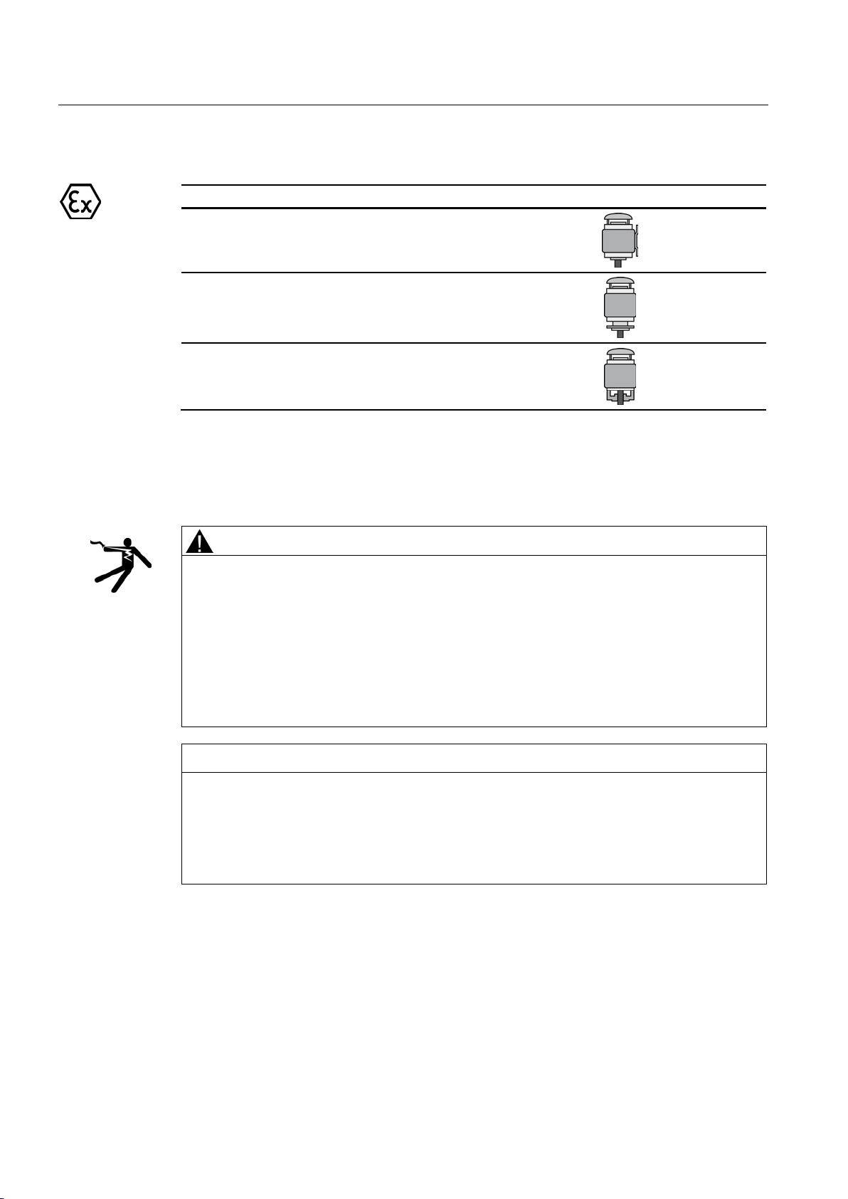
Types of construction/Installation conditions for explosion-proof machines
3.3 Installation
IM B5 (IM 3001)
IM V3 (IM 3031)
IM B14 (IM 3601)
IM V19 (IM 3631)
IM B35 (IM 2001)
IM V1 (IM 3011)
IM V18 (IM 3611)
IM B34 (IM 2101)
The type of construction of the machine is stated on the rating plate.
In the case of explosion-proof machines where the shaft extensions point downwards (types
of construction IM V5, IM V1 or IM V18 ) a protective top cover is mandatory. Explosionproof machines with IM V5, IM V1 and IM V18 types of construction are fitted with a canopy
at the factory.
Low-voltage motors
Operating Instructions, 05/2014, 5 610 00000 02 000
23
Page 24
Description
Conditions of installation
Graphics-Based Representation
3.3.7
Degree of protection
WARNING
Dangerous voltage
NOTICE
Storage
Environmental requirements
3.3 Installation
Table 3- 4 Construction type with protective top cover
IM V5 (IM 1011)
IM V1 (IM 3011)
IM V18 (IM 3611)
The motor degree of protection is stamped on the rating plate. They can be installed in dusty
or humid environments.
The winding can be damaged if objects are introduced into the condensation holes
(optional). This can lead to death, serious injury or material damage.
Note the following to maintain the degree of protection:
• Switch off the machine so that it is in a no-voltage condition, before you open the
condensation drain holes.
• Close the condensation drain holes, e.g. using T-plugs, before commissioning the
machine.
The motor can be damaged if you use it or store it unprotected outdoors.
• Protect the motor against intensive solar radiation, rain, snow, ice and dust. Use a
superstructure or additional cover, for example.
• If required, contact the Siemens Service Center, or technically coordinate outdoors use.
The machine is suitable for tropical climates.
Guide value for the standard version 60 % relative humidity at an ambient temperature of
(T
) 40 °C.
amb
Low-voltage motors
24 Operating Instructions, 05/2014, 5 610 00000 02 000
Ambient temperature: -20 °C to +40 °C
Page 25

Description
3.3.8
Optional built-on and built-in accessories
Optional built-on and built-in accessories for explosion-proof machines
Type of protection
Ex d
Ex e, Ex nA
Supply voltage
Line
Converter
Line
Control range
-
10 Hz to f
rated
(≤ 60 Hz)
-
Cooling method
Self-ventilated
Frame size
63 ... 200
Mechanical design
EN 50347
Ambient temperature
-20° C ... +60° C
-20 °C ... +40 °C
Temperature class
T3, T4
T3
Number of poles
2, 4
2
4
Max. shaft temperature
100 °C
60 °C
75 °C
Max. flange temperature
100 °C
60 °C
75 °C
3.3 Installation
Installation altitude: ≤ 1000 m
Air with normal oxygen content, usually 21 % (V/V)
If the environmental requirements are different from the details listed here, then the values
on the rating plate will apply.
Machines intended for use in Zone 1 (type of protection Flameproof Enclosure "d" or
Increased Safety "e") or in Zone 2 (type of protection "n") are designed with IP 55 degree of
protection.
Machines intended for use in Zone 21 have IP 65 degree of protection. Machines intended
for use in Zone 22 have IP 55 degree of protection and can be used in dusty environments
such as grinders, silos, animal feed plants, and malthouses, as well as in certain areas of the
chemical industry.
In addition to the current-dependent overload protective device located in the connecting
leads, we recommend that you use temperature sensors embedded in the stator winding in
order to monitor the temperature and protect the stator winding from overheating.
Machines whose winding is exposed to the danger of condensation due to the climate, e.g.
machines at a standstill in a damp environment or machines which are exposed to large
temperature fluctuations, can be equipped with an anti-condensation heater.
As an option, the machines can be fitted with additional built-on accessories on the
ventilation side (e.g. brake, rotary pulse encoder).
Investigate the influence of sources of heat and cold on the finished installation when it
includes built-on accessories compliant with EN 60079-14!
Table 3- 5 Recommended maximum interface temperatures for flange motors
Select mounted equipment such as brakes, forced ventilation or incremental encoders according to the
requirements of the Directive 94/9/EC.
Low-voltage motors
Operating Instructions, 05/2014, 5 610 00000 02 000
25
Page 26

Description
3.3 Installation
Low-voltage motors
26 Operating Instructions, 05/2014, 5 610 00000 02 000
Page 27
4
4.1
Delivery
Checking the delivery for completeness
4.2
Transport
WARNING
Risk of dropping and swinging when transported suspended
The drive systems are put together on an individual basis. When you take receipt of the
delivery, please check immediately whether the items delivered are in accordance with the
accompanying documents. Siemens will not accept any claims relating to items missing from
the delivery and which are submitted at a later date.
● Report any apparent transport damage to the delivery agent immediately.
● Report any apparent defects/missing components to the appropriate SIEMENS office
immediately.
Archive the safety and commissioning notes provided in the scope of delivery as well as the
optionally available operating instructions so that these documents are always easily
accessible.
The rating plate optionally enclosed as a loose item with the delivery is provided to enable
the motor data to be attached on or near the machine or installation.
If you transport the motor suspended from cables or ropes, the cables or ropes can break,
e.g. as result of damage. Further, if not adequately attached, the motor can swing. This can
result in death, serious injury, or material damage.
• Use additional, suitable lifting equipment for transport and during installation.
• Two cables alone must be able to carry the complete load.
• Prevent the lifting equipment from sliding by appropriately securing it.
Low-voltage motors
Operating Instructions, 05/2014, 5 610 00000 02 000
27
Page 28
Preparing for use
WARNING
Toppling over or slipping of the motor
moisture
heat
4.3
Storage
Storing outdoors
NOTICE
Damage to the motor
4.3 Storage
The motor can slide or topple over if it is not correctly lifted or transported. This can result in
death, serious injury, or material damage.
• Use all the lifting eyes on the machine.
• Any eyes that are screwed in must be tightly fastened.
• Eyebolts must be screwed in right up to their supporting surface.
• If necessary, use suitable, sufficiently-sized transport equipment such as lifting straps
(EN1492-1) and lashing straps (EN12195-2).
If any transport locks are in place, remove them before commissioning. Store the transport
locks or disable them. Use the transport locks when transporting the motors again or
reactivate the transport locks.
The machines are packed in different ways depending on how they are transported and their
size. If not otherwise contractually agreed, the packaging corresponds to the packing
guidelines according to ISPM (International Standards for Phytosanitary Measures).
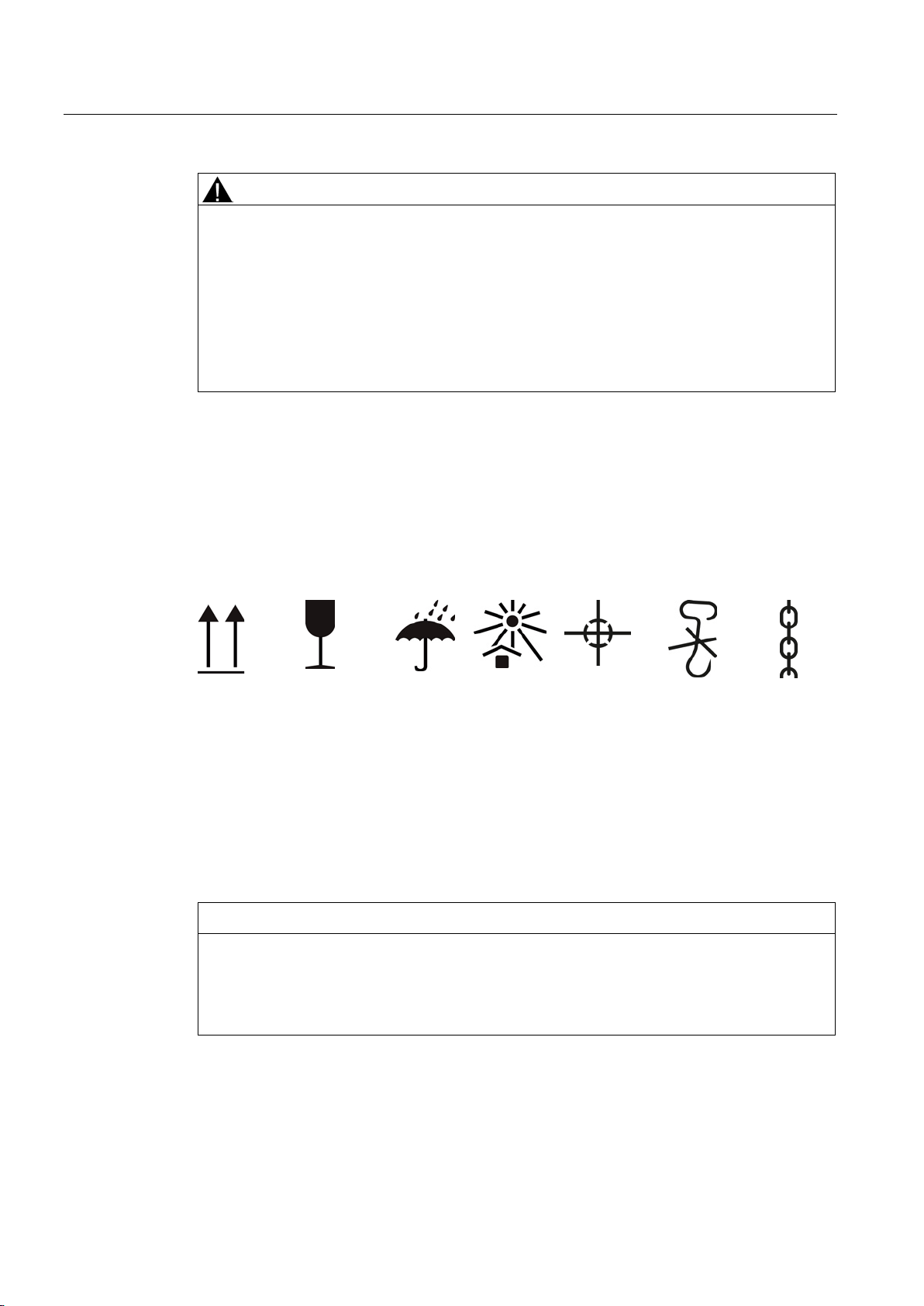
Comply with the images shown on the packaging. Their meaning is as follows:
Up Fragile
goods
Protect
against
Protect
against
Center of
gravity
Hand hooks
forbidden
Attach
here
Damage can occur if incorrectly stored.
Take all precautions to protect the motor under extreme climatic conditions, e.g. salt-laden
and/or dusty, moist/humid atmospheres.
Choose a dry storage location which is safe from flooding and free from vibration. Repair any
damage to the packaging before putting the equipment into storage if this is necessary to
ensure proper storage conditions. In order to ensure protection against ground moisture,
Low-voltage motors
28 Operating Instructions, 05/2014, 5 610 00000 02 000
Page 29

Preparing for use
Storing indoors
Bare metal surfaces
Condensation drain hole
Storage time
Open bearings
Closed bearings
4.4
Electromagnetic compatibility
Note
If the torque levels are very unequal (e.g. when a reciprocating compressor is being driven),
a non
imp
as a result.
4.4 Electromagnetic compatibility
locate machines, equipment and crates on pallets, wooden beams or foundations. Prevent
equipment from sinking into the ground. Do not impede air circulation under the stored items.
Covers or tarpaulins used to protect the equipment against the weather must not come into
contact with the surfaces of the equipment. Use wooden spacer elements to ensure that air
can circulate freely around the equipment.
The storage rooms must provide protection against extreme weather conditions. They must
be dry, free from dust, frost and vibration and well ventilated.
For transport, the bare surfaces (shaft ends, flange surfaces, centering edges) should be
coated with an anti-corrosion agent which will last for a limited amount of time (<6 months).
Apply suitable anti-corrosion measures for longer storage times.
Open any condensation drain holes to drain the condensation depending on the
environmental conditions, every six months at the latest.
Turn the shafts 1x every year to avoid bearing brinelling. Prolonged storage periods reduce
the useful life of the bearing grease (aging).
● For open bearings e.g. 1Z, check the state of the bearing grease over 12 months.
● Replace the grease if it is identified that the grease has lost its lubricating properties or is
polluted. The consistency of the grease will change if condensation is allowed to enter.
● For sealed bearings, replace the DE and NDE bearings after a storage time of 48 months.
-sinusoidal machine current will be induced whose harmonics can have an
ermissible effect on the supply system and cause impermissible interference emissions
Low-voltage motors
Operating Instructions, 05/2014, 5 610 00000 02 000
29
Page 30

Preparing for use
Note
Converter
•
•
•
•
•
Immunity to interference
4.4 Electromagnetic compatibility
If operated with a frequency converter, the emitted interference varies in strength,
depending on the design of the converter (type, interference suppression measures,
manufacturer).
Avoid that the specified limit values stipulated for the drive system (consisting of the
motor and converter) are exceeded.
You must observe the EMC information from the manufacturer of the converter.
The most effective method of shielding is to conductively connect a shielded machine
supply cable to the metal terminal box of the machine (with a metal screw connection)
over a large surface area.
On machines with integrated sensors (e.g. PTC thermistors), disturbance voltages
caused by the converter may occur on the sensor cable.
When used in accordance with their intended purpose and operated on an electrical supply
system with characteristics according to EN 50160, the enclosed machines comply with the
requirements of the EC Directive concerning electromagnetic compatibility.
The machines in principle fulfill the requirements of interference immunity in conformity with
EN / IEC 61000-6-2 . If machines with integrated sensors (e.g. PTC thermistors) are used,
the operating company must ensure sufficient interference immunity by selecting a suitable
sensor signal lead (possibly with shielding, connected in the same way as the machine
feeder cable) and a suitable evaluation unit.
When operating the machines from a converter at speeds higher than the rated speed, then
the mechanical speed limits must be carefully observed (safe operating speed
EN / IEC 60034-1).
Low-voltage motors
30 Operating Instructions, 05/2014, 5 610 00000 02 000
Page 31
5
5.1
Installation
5.1.1
Safety instructions
WARNING
Risk of burning
NOTICE
Damage to the motor
Note
Observe the technical data on the rating plates attached to the motor enclosure.
5.1.2
Safety instructions: Explosion-proof machines
Note
The increased level of danger in hazardous areas demands that yo
to the notes marked with
Electrical machines have hot surfaces.
Fatal or severe injuries and substantial material damage can occur if the required covers
are removed or if the machines are not handled, operated, or maintained properly.
• Allow the machine to cool down before starting any work on it.
• Only remove covers in compliance with the applicable regulations.
• Operate the machines properly.
• Prevent parts (cables, etc.) from coming into contact with the machine enclosure.
In order to avoid material damage, check the following points before commissioning the
motor.
• Using appropriate measures, check whether the correct direction of rotation of the motor
has been set by the customer, e.g. by decoupling from the driven load.
• Ensure that temperature-sensitive parts (cables, etc.) are not in contact with the
machine enclosure.
• Ensure that the condensation drain holes are always located at the lowest part of the
motor.
u pay particular attention
.
Low-voltage motors
Operating Instructions, 05/2014, 5 610 00000 02 000
31
Page 32
Assembly
5.1.3
Machine installation
General
Note
In order to prevent the eyebolts loosening, after mounting, tighten t
NOTICE
Damage to mounted components
5.1 Installation
hese or remove them.
Material damage can occur if you use the mounted components to help lift the motor.
Do not use the mounted components to help lift the motor.
● For vertical installation, use all of the eyebolts provided and when necessary, hoisting
straps (DIN EN 1492-1) and/or lashing straps (DIN EN 12195-2) to stabilize the position
of the motor.
● Prevent foreign bodies from falling into the fan cover. For vertical machine installation
with the shaft end facing downwards, attach a protective canopy.
● If the shaft extension is facing upwards, the user must prevent liquid from moving along
the shaft and entering the motor.
● Clean bare metal surfaces with anti-corrosion agent using white spirit to ensure proper
installation and / or machine mounting.
● Do not obstruct the ventilation! Do not draw in the discharged air directly – also from
adjacent equipment.
● Avoid exposing them to direct, intense solar radiation, rain, snow, ice, or also dust for
extended periods. Attach a covering structure or an additional cover when using or
storing outdoors.
● Do not exceed the permissible axial and radial forces.
● Only use explosion-protected machines in appropriate areas in accordance with directive
1999/92/EG .
If the certificate is supplemented by an X, observe the special conditions listed in the EC
type examination certificate. Special conditions for explosion-proof machines (Page 13)
● When installing electrical systems in hazardous zones, observe EN / IEC 60079-14 and
the corresponding country regulations.
● The machine temperature class specified on the rating plate must be equal to or greater
than the temperature class of any combustible gases that may develop.
Low-voltage motors
32 Operating Instructions, 05/2014, 5 610 00000 02 000
Page 33
Assembly
5.1.4
Cooling
5.1.4.1
Ventilation
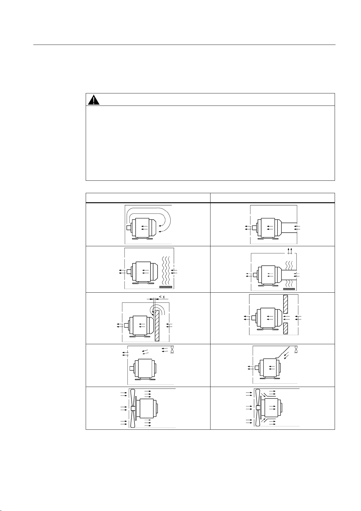
CAUTION
Overheating and failure of the motor
moving along the shaft.
Incorrect
Correct
machine
5.1 Installation
Material damage or slight injury can occur if you do not observe the following points:
• Do not obstruct ventilation.
• Prevent the air expelled by neighboring equipment from being immediately sucked in
again.
• On the vertical type of machine construction with air intake from above, protect the air
inlets from the ingress of foreign bodies and water.
• If the shaft extension is facing upwards, liquid must be prevented from entering by
Table 5- 1 Air guidance
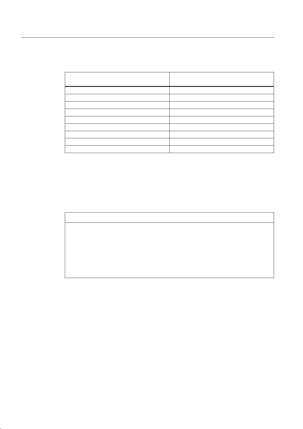
Minimum dimension "x" for the distance between neighboring modules and the air intake of the
Low-voltage motors
Operating Instructions, 05/2014, 5 610 00000 02 000
33
Page 34
Assembly
Frame size
X
[mm]
63 ... 71
15
80 ... 100
20
112
25
132
30
160
40
180 ... 225
45
180 ... 200 (1LG)
90
225 ... 250 (1LG, 1MA6)
100
280 ... 315
110
5.1.5
Machines with type of construction IM B15, IM B9, IM V8 and IM V9
Special types of construction
NOTICE
Damage to the motor
5.1 Installation
Table 5- 2 Minimum dimension "X" for the distance between neighboring modules and the air intake
of the machine
Material damage can occur if the following notes are not observed:
• The IM B3 bearing shield with built-in distance ring mounted at the DE is only used as
transport lock. A warning label is attached to this bearing shield.
• The spacer ring is not a roller bearing.
• Remove the bearing shield and the spacer ring.
• Remove the transport lock before commissioning.
These machines do not have their own bearing system for the machine shaft at the drive end
(DE). The machine shaft is accepted by the (hollow) shaft or coupling of the plant or driven
machine.
Using the centering flange, the machine is aligned with respect to enclosures, flanges or
driven machines.
Note that the temperature of the motor and motor shaft increases during operation. The
thermal expansion of the machine shaft must be compensated by the customer in the form of
suitable measures.
Use the spring washers provided to locate the NDE bearing without any play.
Low-voltage motors
34 Operating Instructions, 05/2014, 5 610 00000 02 000
Page 35
Assembly
5.1.6
Balancing
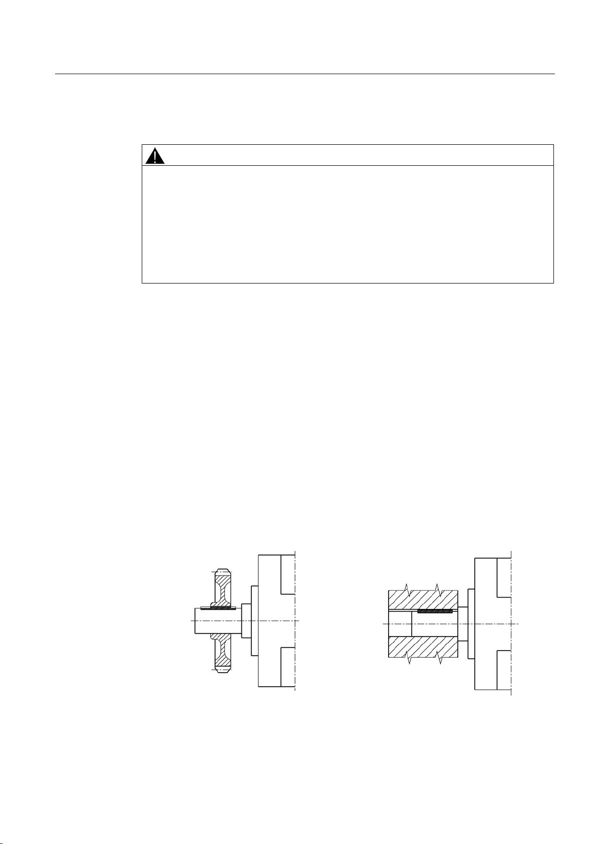
CAUTION
Incorrect mounting or removal
Designation:
5.1 Installation
To avoid injury and material damage, carefully observe general touch protection measures
for output transmission elements.
• The general touch protection measures for drive output elements must be observed.
• Output elements may only be attached or withdrawn using the correct equipment.
• The feather keys are only secured against falling out during shipping. If you commission
a machine without an output element, the feather keys must be secured to prevent them
from being thrown out.
The rotor is dynamically balanced. The balancing quality corresponds to vibration severity
grade "A" for the complete machine as standard. The optional vibration severity grade "B" is
indicated on the rating plate.
The declaration regarding the type of featherkey for balancing is generally marked on the
rating plate and optionally on the face of the shaft end.
● As a standard measure, balancing is carried out dynamically with a half featherkey (code
"H") in accordance with ISO 8821.
● "F" means balancing with a whole featherkey (optional version).
● "N" means balancing without a featherkey (optional version).
The featherkey data on the shaft and transmission element must indicate the correct type of
balancing in each case and must be correctly mounted.
The balancing quality corresponds to vibration severity grade "A" for the complete machine;
vibration severity grade "B" is possible as an option, i.e. in order to ensure the desired
balancing quality, it must be ensured that the featherkey data on the hub and machine shaft
complement each other in the case of a shorter or longer output transmission element.
Low-voltage motors
Operating Instructions, 05/2014, 5 610 00000 02 000
Measures conforming to ISO 10816 must be taken in order to compensate any offset
between electrical machines and driven machines.
The foundation must be designed according to DIN 4024.
35
Page 36
Assembly
5.1.6.1
Mounting and withdrawing output transmission elements
Withdrawing output transmission elements
Mounting output transmission elements
5.1 Installation
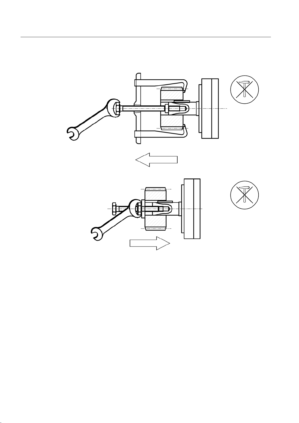
● When mounting output transmission elements (coupling, gear wheel, belt pulley etc. ) use
the thread at the shaft end.
If possible, heat up the output transmission elements as required.
● Use a suitable device when withdrawing output elements.
● When mounting or withdrawing, do not apply any blows, for example with a hammer or
similar tool, to the parts to be mounted or withdrawn.
● Only transfer radial or axial forces specified in the catalog to the motor bearings via the
shaft extension.
Low-voltage motors
36 Operating Instructions, 05/2014, 5 610 00000 02 000
Page 37
Assembly
5.1.7
Noise emission
CAUTION
Hearing damage when operating three-phase motors
5.2
Alignment and fastening
Measures
Vertical positioning.
Horizontal positioning
Smooth running
5.2 Alignment and fastening
If you exceed the permissible sound pressure level, hearing damage can occur when
operating three-phase motors at their rated power.
Observe the maximum permissible sound pressure level according to the ISO 1680
standard. The maximum permissible sound pressure level is 70 dB (A).
When aligning and mounting, please observe the following:
● Uniform mounting surface
● Mounting feet and flanges are securely fixed.
● Precise alignment for a direct coupling
● Mounting surfaces must be clean
● Repair any damage to the paint, this must be done immediately and correctly.
● Remove any anti-corrosion protection using white spirit.
● Avoid installation-related resonances with the rotating frequency and twice the line
frequency.
● Listen for unusual noises when turning the rotor manually.
● Check the direction of rotation with the machine decoupled.
● Avoid rigid couplings.
The following measures are required in order to compensate any radial offset at the coupling
and to horizontally adjust the electrical machine with respect to the driven load:
●
When vertically positioning the machine, place thin metal shins under the mounting feet in
order to avoid tensioning and deforming the motor. The number of shims should be kept
as low as possible i.e. only stack a few shims.
●
To position the machine horizontally, shift it sideways on the foundation and ensure that
the axial position is maintained (angularity error).
● When positioning the motor, ensure that a uniform axial gap is maintained around the
coupling.
●
Stable, vibration-free design of the foundations in accordance with DIN 4024 and precise
Low-voltage motors
Operating Instructions, 05/2014, 5 610 00000 02 000
37
Page 38
Assembly
Foot/flange mounting
Note
Only au
feet at the machine enclosure.
In order to avoid stressing and deforming the motor, ensure that the foot mounting
surfaces are aligned in one plane and are parallel to the machi
machine the
foot mounting surfaces or use thin shims, for example.
5.2.1
Flatness of supporting surfaces
Flatness of the supporting surfaces for conventional motors
Frame size
Flatness
[mm]
≤ 132
0,10
160
0,15
≥ 180
0,20
5.2.2
Machine frame mounting feet (special design)
Note
For terminal boxes mounted at the NDE (option H08), dimension C can deviate from EN
50347.
For motors with double or triple holes at the NDE, maintain the foot mounting
specified in standard EN
5.2 Alignment and fastening
alignment of the coupling, as well as a well-balanced transmission element (coupling, belt
pulleys, fans, etc.), are prerequisites for smooth running with low vibration.
Maximum permissible vibration in operation according to ISO 10816 must be complied
with.
Inadmissible vibration caused for example, by imbalance (drive output element), external
vibration or any resonance in the complete speed range must be avoided.
It may be necessary to completely balance the machine with the drive output element or
the system resonance frequency must be shifted.
●
Use thread sizes specified in EN 50347 for mounting the motor to foundations or to
machine flanges. Attach the machine at four foot or flange holes in a rectangular
configuration with respect to one another. The customer is responsible for selecting the
strength of the fixing elements.
For the fixing elements up to and including frame size 160, property class 5.6 or higher is
recommended, from frame size 180, property class 8.8 or higher.
For IM B14 flanges, select the correct screw length.
thorized retrofit partners must be employed to relocate the bolted on mounting
ne shaft. Post-
50347 .
Low-voltage motors
38 Operating Instructions, 05/2014, 5 610 00000 02 000
dimensions as
Page 39
6
6.1
Connecting the machine
6.1.1
General
DANGER
Hazardous voltages
DANGER
Hazardous voltages
Death, injury or material damage can occur. Note the following safety information before
connecting-up the machine:
• Only qualified and trained personnel should carry out work on the machine while it is
stationary.
• Disconnect the machine from the power supply and take measures to prevent it being
reconnected. This also applies to auxiliary circuits.
• Check that the machine really is in a no-voltage condition.
• Establish a safe protective conductor connection before starting any work.
• If the incoming power supply system displays any deviations from the rated values in
terms of voltage, frequency, curve form or symmetry, such deviations will increase the
temperature and influence electromagnetic compatibility.
Low-voltage motors
Operating Instructions, 05/2014, 5 610 00000 02 000
Death, injury or material damage can occur. Operating the machine on a line supply system
with a non-grounded neutral point is only permitted over short time intervals that occur
rarely, e.g. the time leading to a fault being eliminated (ground fault of a cable, EN 60034-
1).
Observe the information in EN / IEC 60034-1 (VDE 0530-1) regarding operation at the limits
of the A zones (±5 % voltage difference and ±2 % frequency difference) and the B zones,
especially in respect of temperature increase and deviation of the operating data from the
rated data on the rating plate. Never exceed the specified limits!
Connect up so that a permanently safe electrical connection is guaranteed (no protruding
wire ends); use the assigned cable-end fittings (e.g. cable lugs, end sleeves).
Connect up the line supply voltage and arranged the disconnecting link in accordance with
the circuit diagram provided in the terminal box.
Select connecting cables according to DIN VDE 0100 taking into account the rated current
and the system-dependent conditions (e.g. ambient temperature, routing type etc. according
to DIN VDE 0298 or EN / IEC 60204-1).
39
Page 40

Electrical connection
6.1 Connecting the machine
The technical specifications stipulate the following that have to be taken into account with
respect to the motor connection:
● Direction of rotation.
● The number and arrangement of the terminal boxes.
● The circuit and connection of the machine winding.
The following features make this type of electrical connection different from that for standard
machines:
● Maintain the area A in EN / IEC 60034-1 (VDE 0530-1) (±5 % voltage or ±2 % frequency
deviation, waveform, line supply symmetry) so that the temperature rise remains within
the permissible limits.
● Larger deviations from the rated data may result in electrical machines heating up to
impermissible levels. This information must be specified on the rating plate. Under no
circumstances exceed the limits!
● Protect every machine with type of protection increased safety "e" in accordance with
EN / IEC 60079-14 against an inadmissible temperature rise using a current-dependent,
delayed circuit breaker with phase failure protection and asymmetry detection
corresponding to EN / IEC 60947 or using an equivalent device in all phases.
● For machines with type of protection increased safety "e", select the overcurrent device
with current-dependent delayed trip so that the tripping time, which should be taken from
the characteristic of the switch for the ratio I
longer than the safe-locked rotor time t
rotor time t
from the rating plate. Set the protective device to the rated current. Use a
E
/ IN of the machine to be protected, is no
A
. Take the ratio IA / IN as well as the safe-locked
E
certified tripping unit in accordance with RL 94/9/EC.
● For machines with increased safety "e" type of protection, in the event of a locked rotor
the protective device must disconnect within the t
time specified for the relevant
E
temperature class. Protect electrical machines for heavy duty starting (acceleration time >
1.7 x t
time) according to the specifications of the EC-type examination certificate using
E
a starting monitoring function.
Direct monitoring of the winding temperature is permissible as a means of thermal
machine protection, provided that this is certified and specified on the rating plate.
● With pole-changing machines, separate, interlocked protective devices are required for
each speed step. Devices with an EC-type examination certificate are recommended.
Low-voltage motors
40 Operating Instructions, 05/2014, 5 610 00000 02 000
Page 41
Electrical connection
6.1.2
Terminal designations
1 U 1 - 1
Designation
subdivided winding.
x
Phase designation (U, V, W)
more than one connection per winding)
feed cables to several terminals with otherwise identical designations
6.1.3
Direction of rotation
6.1.4
Connection with/without cable lugs
Note
The direct contact betw
ensure that the connection can conduct current.
6.1 Connecting the machine
With the terminal designations according to DIN VDE 0530 Part 8 or EN / IEC 60034-8 for
three-phase machines, the following principle definitions apply:
Table 6- 1 Terminal designations (with the 1U1-1 as an example)
x Index showing the pole assignment for pole-changing machines (where
applicable, a lower number indicates a lower speed) or, in special cases, for a
x Index showing the start (1) / end (2) or tapping point of the winding (if there is
x Additional index for cases in which it is obligatory to connect parallel power
The standard motors are suitable for clockwise and counter-clockwise rotation.
Connection of the power cables in the phase sequence L1, L2, L3 to U1, V1, W1 results in
clockwise rotation (looking at the DE shaft end on the drive side). If two of the connections
are interchanged, then the resulting direction of rotation is counter-clockwise (e.g. L1, L2, L3
to V1, U1, W1).
In the case of machines intended for only one direction of rotation, the defined direction of
rotation e.g. for machines with an axial fan, is marked by a direction arrow on the machine.
In the case of terminals with terminal clamps, distribute the conductors in such a way that the
clamping heights on both sides of the fillet are about the same. This method of connection
requires that you must bend a single conductor in a U shape or use a cable lug. The same
applies to the inner and outer terminals of the ground conductor.
When connecting up using cable lugs, select their size corresponding to the required cable
cross-section and the stud size. An inclined arrangement is only permitted provided the
required air clearances and creepage distances are carefully maintained.
Remove the insulation from the conductor ends so that the remaining insulation is almost
long enough to reach the cable lug.
een the cable lug surfaces and the contact nuts or contact screws
Low-voltage motors
Operating Instructions, 05/2014, 5 610 00000 02 000
41
Page 42
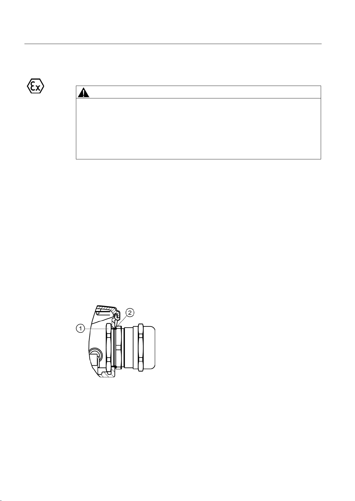
Electrical connection
6.1.5
Connection with cable lug for explosion-protected machines
WARNING
Short-circuit hazard
6.1.6
Connecting protruding cables
6.1.7
Cable glands
Cable glands with (sheet metal) nuts (EN 50262)
①
②
Nut
O ring
6.1 Connecting the machine
Live conductors released from the terminal board can cause short circuits. Death or serious
physical injury can result.
• You must bend single-core line conductors into a U shape in order to prevent the
contact force being transferred at just one side.
• In order to prevent the cable lug from rotating, for a line connection using a cable lug,
angle single- or multi-core cables downwards through an angle of approx. 40°.
In the case of connection cables brought out of the machine, no terminal board is installed
on the terminal base of the machine housing. The connection cables are directly connected
to stator winding terminals at the factory.
The connection cables are color-coded or labeled. The customer directly connects individual
cables in the control cabinet for their system in accordance with the labeling.
Low-voltage motors
42 Operating Instructions, 05/2014, 5 610 00000 02 000
Page 43
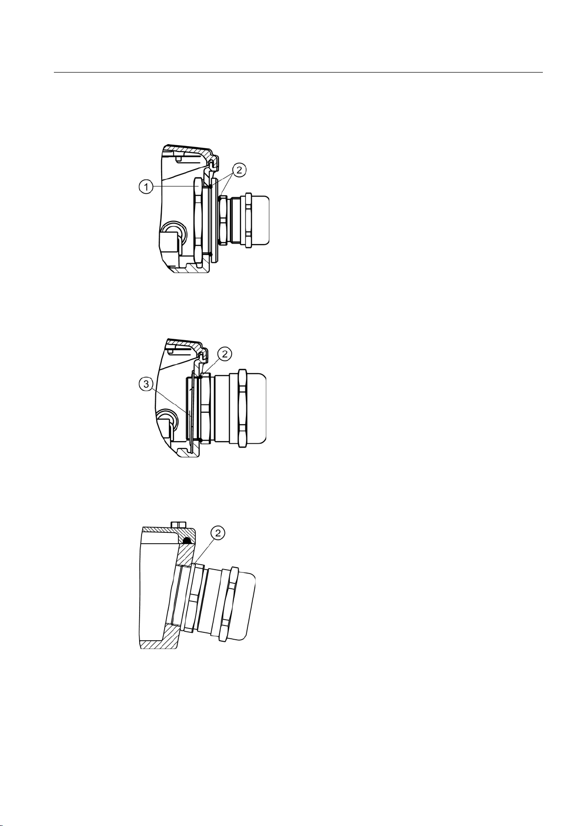
Electrical connection
Cable glands with reductions and (sheet metal) nuts (EN 50262)
①
②
Nut
O ring
6.1.7.1
Mounting position of sheet metal nuts in screw-type connections
②
③
O ring
Mounting position of metal
nuts
Cable glands with connecting thread in the terminal box (EN 50262)
②
O ring
6.1 Connecting the machine
-sheet
Low-voltage motors
Operating Instructions, 05/2014, 5 610 00000 02 000
43
Page 44
Electrical connection
6.1.8
Terminal box
6.1.8.1
General
DANGER
Hazardous voltage
NOTICE
Damage to the terminal box
Terminal box- terminal board versions, 1LE 80...90
6.1 Connecting the machine
Electric motors have high voltages. When incorrectly handled, this can result in death or
severe injury.
Switch off the machine so that it is in a no-voltage condition before you open the terminal
box.
If you incorrectly carry out work on or in the terminal box, this can result in material
damage. You must observe the following to avoid damaging the terminal box:
• Ensure that the components inside the terminal box are not damaged.
• It must be ensured that there are no foreign bodies, dirt or moisture in the terminal box.
• Close the terminal box using the original seal so that it is dust tight and water tight.
• Use O-rings or suitable flat gaskets to seal entries in the terminal box (DIN 42925) and
other open entries.
• Please observe the tightening torques for cable glands and other screws.
• When performing a test run, secure the feather keys without output elements.
Low-voltage motors
44 Operating Instructions, 05/2014, 5 610 00000 02 000
Machines, frame sizes 80 … 90, are supplied with different terminal boards depending on
the winding as well as the type and number of installed parts.
Page 45
Electrical connection
WARNING
Hazardous voltage
NOTICE
Serious damage to the machine
6.1.8.2
Versions
Standard design
6.1 Connecting the machine
Loosening the safety torx screw can result in death, serious injury or material damage.
Do not loosen the safety torx screw with respect to the center terminal, as this ensures a
conductive connection between the grounding conductor and frame!
Failure to observe these measures will destroy the motor.
• Only rotate the terminal box if the connection cables have still not been laid.
• If you release the safety torx screw at both sides of the outer connecting terminals, this
can destroy the machine.
• Remove the three large snap hooks on the terminal board before rotating the the
terminal box. Keep the snap hooks pressed while rotating the terminal box and use a
screwdriver to re-engage when finished.
It is possible to turn the top side of a machine terminal box 4 x 90 degrees (if screwed on).
The terminal box can be turned 4x90 degrees on the terminal base of the machine's housing
in the case of a terminal board with 6 terminal studs (standard design).
For machines with frame sizes 80 ... 90, with central terminal box locking (basic or optional
terminal board), the terminal box can be rotated continuously through 360 degrees.
Low-voltage motors
Operating Instructions, 05/2014, 5 610 00000 02 000
45
Page 46
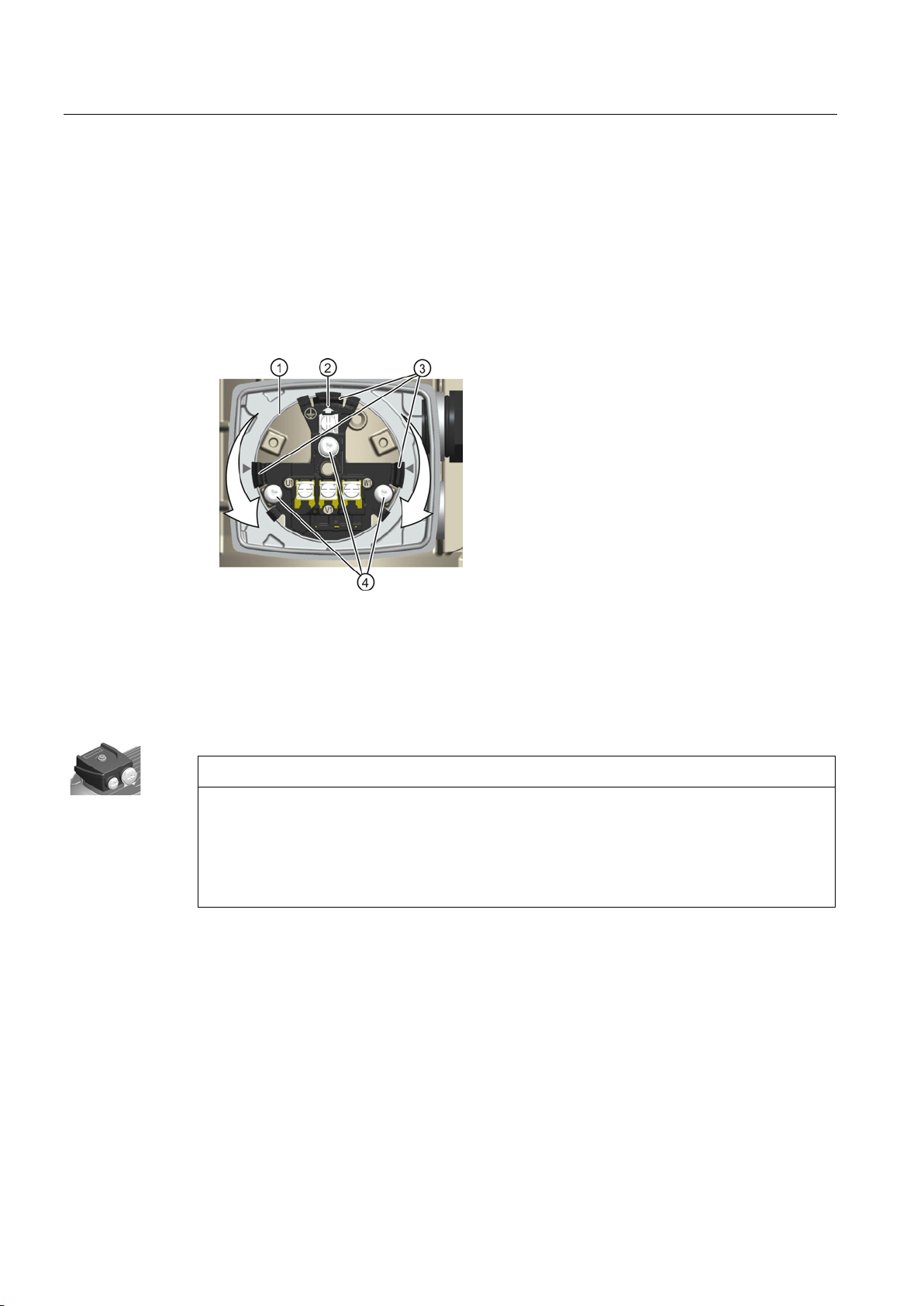
Electrical connection
Installation instructions
①
Flange
②
Terminal box positioner
③
Snap hooks
④
Safety Torx screws
Optional terminal board (star or delta circuit)
NOTICE
Arcing at the optional terminal board can destroy the machine
Connection system for the optional terminal board
Optional terminal board (star or delta circuit)
6.1 Connecting the machine
1. Press the three large snap hooks ③ over the flange ① of the terminal box towards the
inside.
2. Hold the snap hooks
rotate it to the required POSITION. Observe the arrow for the position of the terminal box
③ pressed inwards, detach the terminal box, raise it slightly and
②.
3. Press the terminal box lightly towards the machine housing. Use a screwdriver to allow
the large snap hooks
③ to engage over the flange ① of the terminal box.
In order to prevent destroying the machine, it is absolutely essential that you comply with
the following note:
To change the operating mode, always press the jumper fully into the base of the slot and
use the red locking lever to ensure that it is engaged.
You can use the jumpers to set the operating mode for machines that have an optional
terminal board.
Low-voltage motors
46 Operating Instructions, 05/2014, 5 610 00000 02 000
Page 47
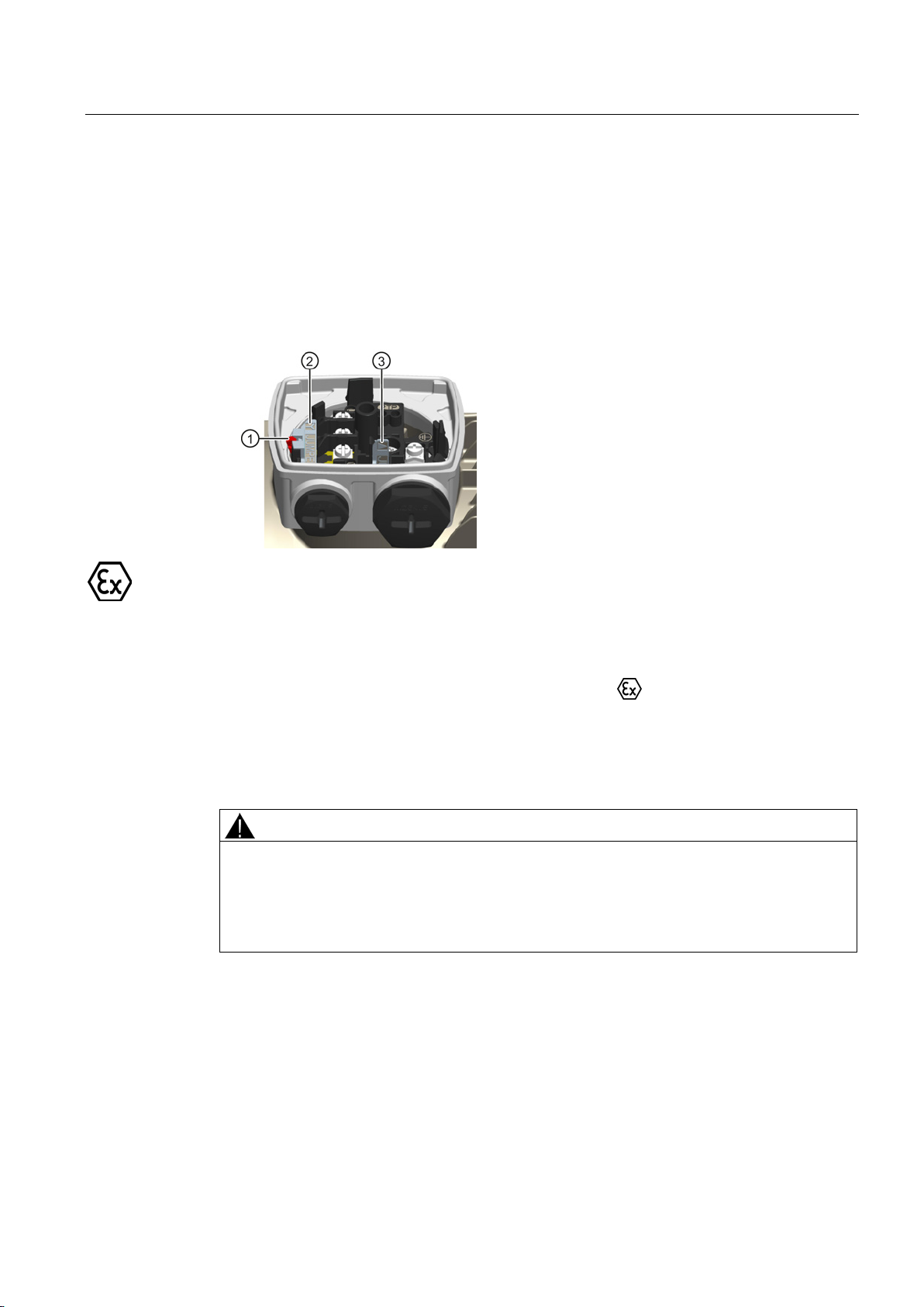
Electrical connection
Installation instructions
6.1.8.3
Protruding connection cables
WARNING
Risk of short-circuit and voltage hazard
6.1 Connecting the machine
1. Open the red locking lever ① and remove the jumper ② from the slot.
2. Release the snap hook on the compartment and remove the jumper
3. Press the jumper
③ fully into the base of the slot and engage the locking lever at its end
③.
position.
4. Press the jumper
② into the compartment and allow the snap hooks to re-engage at the
compartment.
Explosion-protected machines (with the exception of machines for Zone 22) are equipped
with terminal boxes with type of protection increased safety "e".
For 1MJ machines, terminal boxes with type of protection flameproof enclosure "d" with
explosion group IIC are available as an option.
Please note in this regard design, connection options and spare parts.
Note the explosion protection information designated with
in the operating instructions!
Have authorized Siemens workshops perform any repairs.
A short-circuit can occur if the connecting cables are clamped between the enclosure parts
and cover plate. This can result in death, severe injury and material damage.
During disassembly and particularly when installing the cover plate, make sure that the
connecting cables are not clamped between enclosure parts and the cover plate.
Low-voltage motors
Operating Instructions, 05/2014, 5 610 00000 02 000
47
Page 48
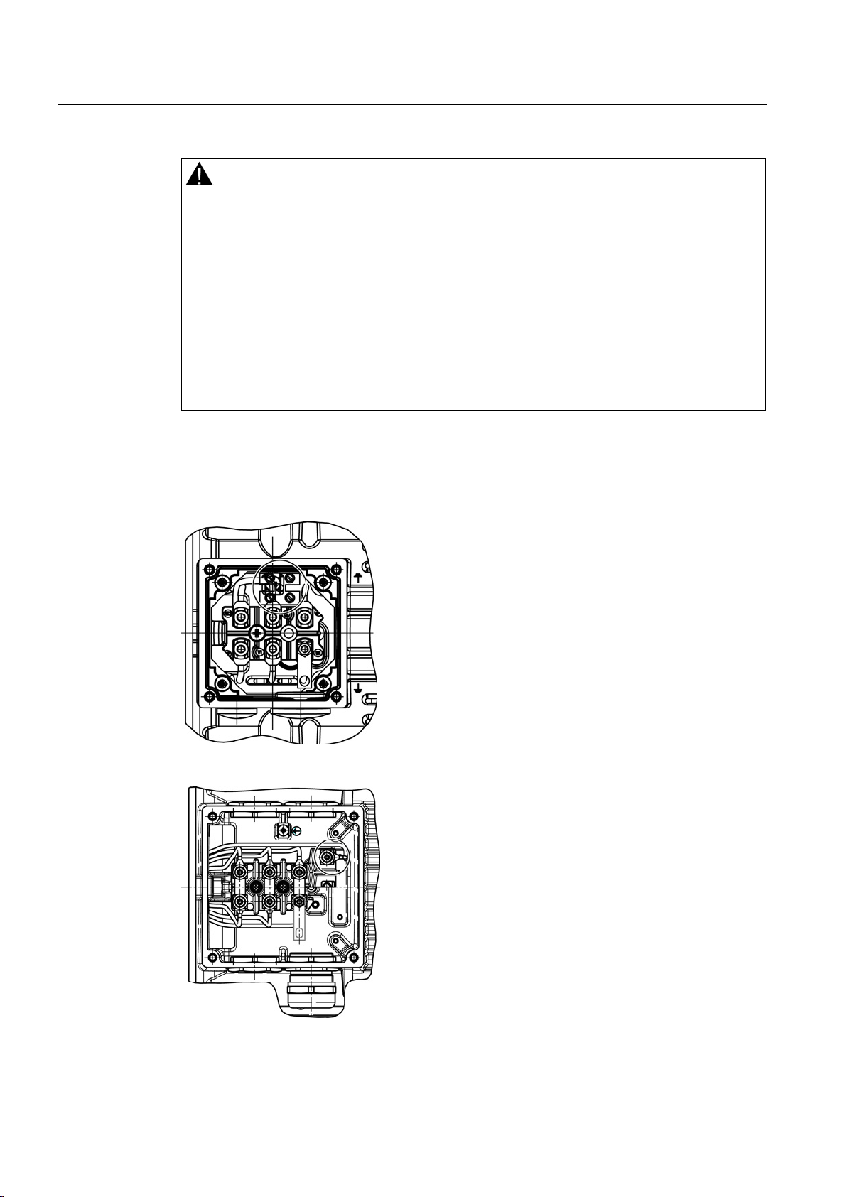
Electrical connection
CAUTION
Damage to connecting cables that are freely led out
6.1.8.4
Connecting the temperature sensor/anti-condensation heater
6.1 Connecting the machine
You must observe the following note to avoid damaging connecting cables that are freely
led out:
• It must be ensured that there are no foreign bodies, dirt, or moisture in the terminal base
of the machine enclosure.
• Use O-rings or suitable flat gaskets to seal entries in cover plates (DIN 42925) and other
open
entries.
• Seal the terminal base of the machine enclosure using the original seal of the cover
plate to prevent dust and water from entering.
• Please observe the tightening torques for cable glands and other screws.
Auxiliary circuits are connected in the terminal box.
Figure 6-1 Connection to terminal strip
Figure 6-2 Connection to terminal board
Low-voltage motors
48 Operating Instructions, 05/2014, 5 610 00000 02 000
Page 49
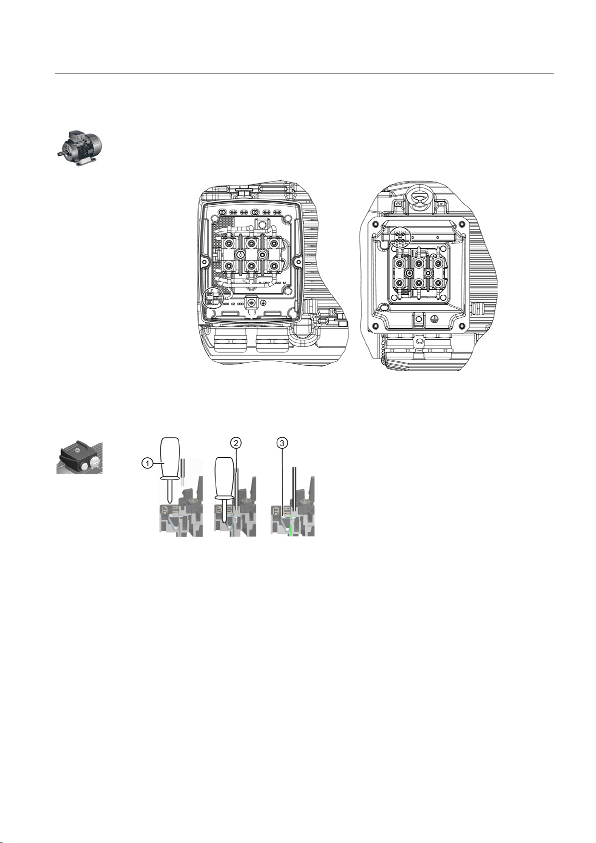
Electrical connection
Connection at the temperature sensor using a spring-loaded connection system
①
Flat-head screwdriver
②
Sensor cable
③
Tension spring
6.1 Connecting the machine
The temperature sensor / anti-condensation heater is connected in the terminal box.
Table 6- 2 Connection to terminal strip
Aluminum Cast iron
Low-voltage motors
Operating Instructions, 05/2014, 5 610 00000 02 000
49
Page 50
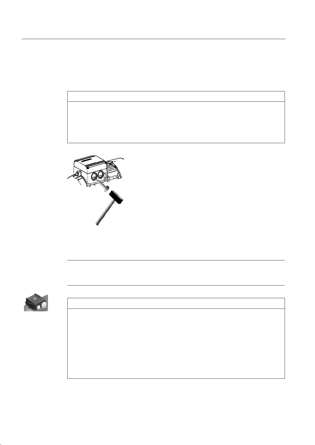
Electrical connection
6.1.8.5
Cable entry
Knockout openings
NOTICE
Damage to the terminal box
Assembly and laying of cables
Note
The screw
(armoring, braid, shield).
NOTICE
Damage to terminal board
6.1 Connecting the machine
You must observe the following notes to avoid damaging the terminal box:
• Knockout openings in the terminal box must be knocked out using appropriate methods.
• Take care not to damage the terminal box or its interior components (the terminal board,
cable connections, and so on).
Screw the screw-type connection into the housing or fasten with a nut.
-type connections must have been matched to the connecting cables used
The terminal board can be damaged for incorrect installation and routing. You must apply
the following measures to avoid damaging the terminal board:
• Remove the screw-type connections (EN 50262) only when the terminal box is closed.
• Tighten the screw-type connections to rated torque value only when the terminal box is
closed.
• Tighten the screw-type connections only finger tight when the terminal box is open.
• Make sure that the three large snap hooks are engaged when tightening the screw
connections.
Low-voltage motors
50 Operating Instructions, 05/2014, 5 610 00000 02 000
Page 51
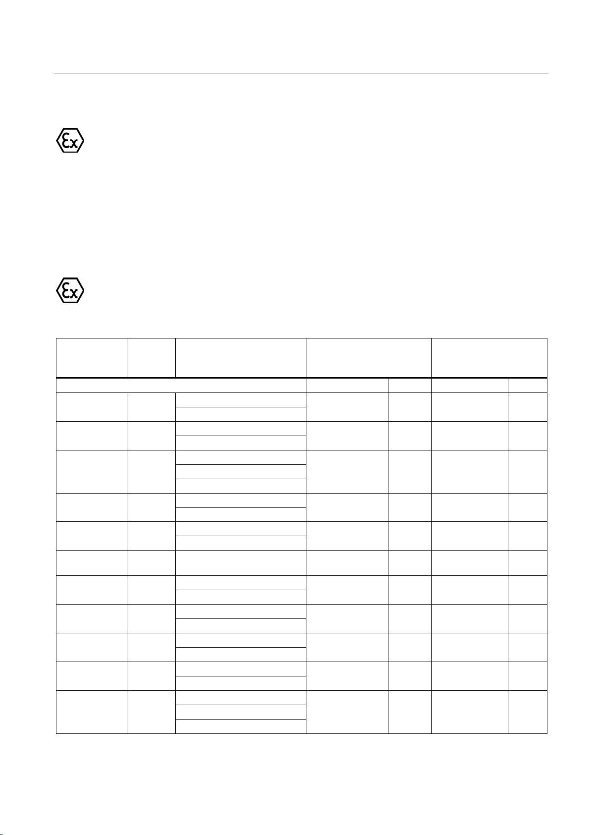
Electrical connection
Cable entries for explosion-proof machines
6.1.8.6
Thread sizes in terminal box
Frame size
Type
Type of protection /
Zone
Standard thread
Additional
thread
with mounting parts
Size
Number Size
Number
Increased safety "e"
Flameproof enclosure "d"
Zone 21
Increased safety "e"
Non sparking "n"
Zone 22
Increased safety "e"
Zone 21
Flameproof enclosure "d"
Zone 21
1MA6
Increased safety "e"
Zone 21
Flameproof enclosure "d"
Zone 21
Increased safety "e"
Zone 21
Flameproof enclosure "d"
Zone 21
Zone 21
6.1 Connecting the machine
The cable glands must have an EC-type examination certificate and be certified for the
respective hazardous zone.
● Any openings that are not being used must be sealed using the corresponding certified
plugs.
● Please observe the manufacturer's specifications when fitting cable entries.
● Before installing the cable, remove the dust protection element or plug from the cable
gland.
Table 6- 3 Thread sizes in the cast iron terminal box
71 ... 90 1MJ6
71 ... 90 1MJ6
100 ... 132 1LA6
100 ... 132 1MJ6
100 ... 132 1MJ6
1MA6
Zone 21
M 25x1.5
M 16x1.5
M 25x1.5 1 M 20x1.5 1
M 32x1.5 2 M 16x1.5 1
M 32x1.5
M 16x1.5
M 32x1.5
2
1
2
1
1
- -
- -
M 20x1.5 1
160 1LA6
160M/L 1MJ6
160 1MJ6
180 1MA6
180 1MJ6
180 1LG4
Low-voltage motors
Operating Instructions, 05/2014, 5 610 00000 02 000
Increased safety "e" M 40x1.5 2 M 16x1.5 1
M 40x1.5 2 M 16x1.5 2
M 40x1.5 1 M 20x1.5 1
M 40x1.5 2 M 16x1.5 2
1MJ6
M 40x1.5 1 M 20x1.5 1
Non sparking "n" M 40x1.5 2 M 20x1.5 2
1LG6
Zone 22
51
Page 52
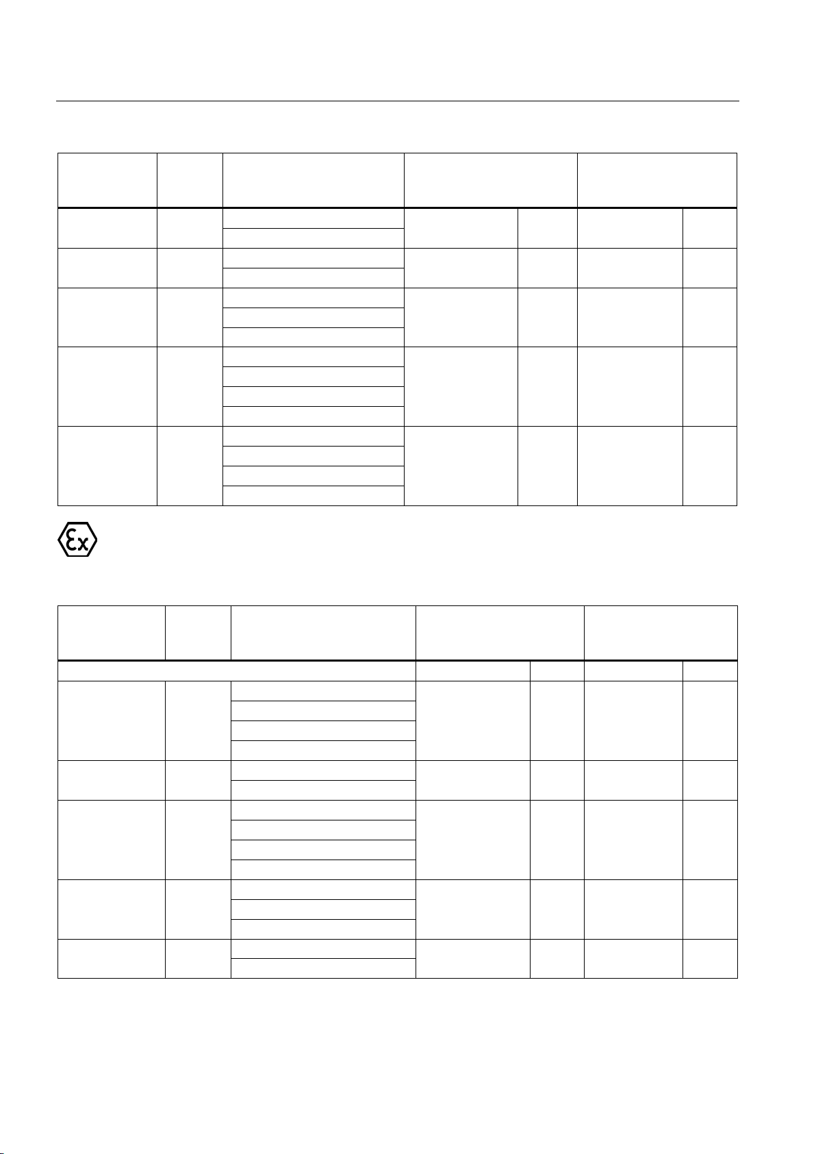
Electrical connection
Frame size
Type
Type of protection /
Zone
Standard thread
Additional
thread
with mounting parts
Increased safety "e"
Zone 21
Flameproof enclosure "d"
Zone 21
Non sparking "n"
Zone 21
Zone 22
Increased safety "e"
Non sparking "n"
Zone 21
Zone 22
Increased safety "e"
Non sparking "n"
Zone 21
Zone 22
Frame size
Type
Type of protection /
Zone
Standard thread
Additional
thread with
mounting parts
Size
Number
Size
Number
Increased safety "e"
Non sparking "n"
Zone 21
Zone 22
Increased safety "e"
Zone 21
Increased safety "e"
Zone 21
Zone 22
Non sparking "n"
Zone 21
Zone 22
Increased safety "e"
Zone 21
6.1 Connecting the machine
200 1MA6
1MJ6
200 1MJ6
200 1LG4
1LG6
225 1LG4
1LG6
1MA6
250 ... 315 1LG4
1LG6
1MA6
Table 6- 4 Thread sizes in the aluminum terminal box
M 50x1.5 2 M 16x1.5 2
M 50x1.5 1 M 20x1.5 1
M 50x1.5 2 M 20x1.5 2
M 50x1.5 2 M 20x1.5 2
M63 x 1.5 2 M 20x1.5 2
63 ... 90 1LA7
1LA9
1MA7
71 ... 90 1MJ6
100 ... 132 1LA7
1LA9
1MA7
100 ... 132 1MB1
100 ... 132 1MJ6
Low-voltage motors
Non sparking "n"
M 16 x 1.5
M 25 x 1.5
M 25x1.5 2 M 16x1.5 1
M 32x1.5 4 - -
M 32x1.5 2 M 16x1.5 1
M 32x1.5 2 M 16x1.5 1
1
1
- -
52 Operating Instructions, 05/2014, 5 610 00000 02 000
Page 53
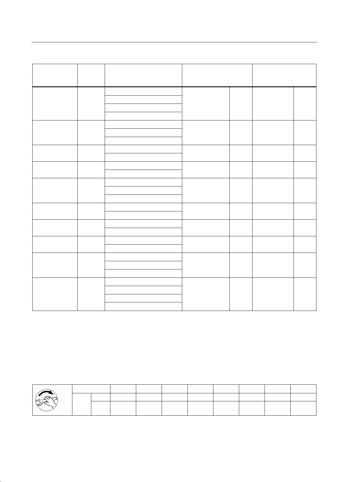
Electrical connection
Frame size
Type
Type of protection /
Zone
Standard thread
Additional
thread with
mounting parts
Increased safety "e"
Non sparking "n"
Zone 21
Zone 22
Non sparking "n"
Zone 21
Zone 22
Increased safety "e"
Zone 21
Zone 21
Zone 22
Non sparking "n"
Zone 21
Zone 22
Increased safety "e"
Zone 21
Zone 22
Zone 21
Non sparking "n"
Zone 21
Zone 22
Increased safety "e"
Non sparking "n"
Zone 21
Zone 22
6.2
Tightening torques
6.2.1
Electrical connections - Termincal board connections
Thread ∅
M 3,5
M 4
M 5
M 6
M 8
M 10
M 12
M 16
Nm
min
0,8
0,8
1,8
2,7
5,5 9 14
27
6.2 Tightening torques
160 1LA7
1LA9
1MA7
160 1MB1
160M 1MJ6
180 1LA5
180 1LG4
1LG6
180 1MA6
1MJ6
200 ... 225 1LA5 Zone 21 M 50x1.5 2 M 16x1.5 1
200 1MA6
1MJ6
200 1LG4
1LG6
Increased safety "e" M 50x1.5 2 M 16x1.5 2
M 40x1.5 4 - -
M 40x1.5 2 M 16x1.5 1
M 40x1.5 2 M 16x1.5 1
M 40x1.5 2 M 16x1.5 1
M 40x1.5 2 M 20x1.5 2
M 40x1.5 2 M 16x1.5 2
M 50x1.5 2 M 20x1.5 2
225 1LG4
1LG6
1MA6
M 50x1.5 2 M 20x1.5 2
Table 6- 5 Tightening torques for electrical connections on the terminal board
Low-voltage motors
Operating Instructions, 05/2014, 5 610 00000 02 000
Max. 1,2 1,2 2,5 4 8 13 20 40
53
Page 54
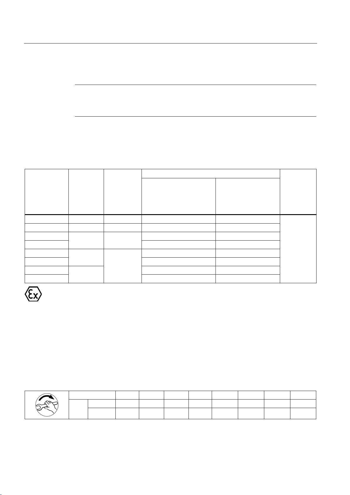
Electrical connection
6.2.2
Cable glands
Note
Avoid damaging the cable jacket.
Adapt the tightening torques to the cable jacket materials.
Metal
± 10%
[Nm]
Plastic
± 10%
[Nm]
Clamping range [mm]
O ring
Cord dia.
[mm]
Standard
-30 °C ... 100 °C
Ex
-30 °C ... 90 °C
Ex
-60 °C ... 105 °C
M 12 x 1.5
8
1,5
3,0 ... 7,0
-
M 16 x 1.5
10 2 4,5 ... 10,0
6,0 ... 10,0
M 20 x 1.5
7,0 ... 13,0
6,0 ... 12,0
M 25 x 1.5
9,0 ... 17,0
10,0 ... 16,0
M 32 x 1.5
11,0 ... 21,0
13,0 ... 20,0
M 40 x 1.5
19,0 ... 28,0
20,0 ... 26,0
M 50 x 1.5
M 63 x 1.5
34,0 ... 45,0
-
6.2.3
Terminal boxes, end shields, grounding conductors, sheet metal fan covers
Thread ∅
M 4
M 5
M 6
M 8
M 10
M 12
M 16
M20
Nm
min 2 3.5 6 16
28
46
110
225
6.2 Tightening torques
You should refer to the table in order to find the correct tightening torque for any metal and
plastic cable glands that are to be mounted directly on the machine, as well as for any other
screw-type connections (such as adapters).
Table 6- 6 Tightening torques for cable glands
12 4
18
6
20 26,0 ... 35,0 25,0 ... 31,0
2
The cable glands must have an EC-type examination certificate and be certified for the
respective hazardous zone.
● Any openings that are not being used must be sealed using using the appropriate
certified plugs.
● Please observe the manufacturer's specifications when fitting cable glands.
If no other tightening torques are specified, then the values in the following table apply.
Table 6- 7 Tightening torques for screws on the terminal box, end shields, screw-type grounding conductor connections
max 3 5 9 24 42 70 165 340
Low-voltage motors
54 Operating Instructions, 05/2014, 5 610 00000 02 000
Page 55
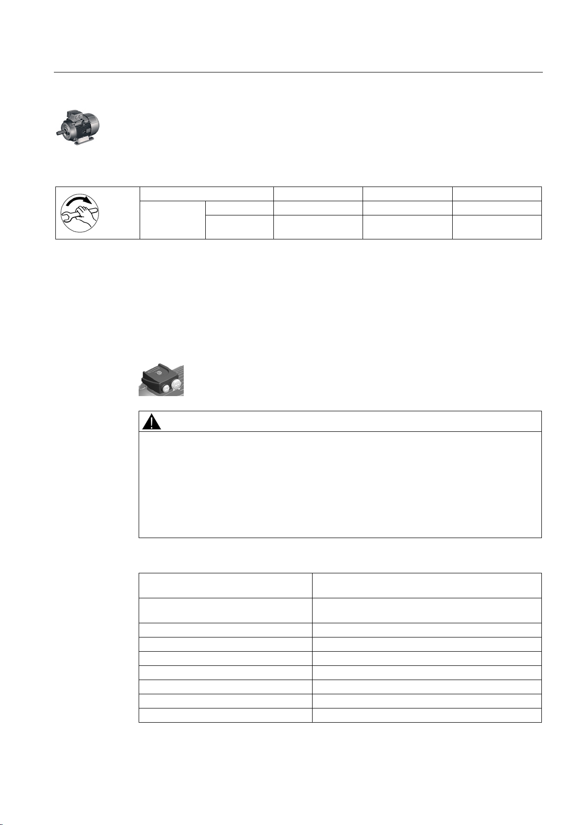
Electrical connection
Thread ∅
M 4
M 5
M 6
Nm
min 4 7,5
12,5
6.3
Conductor connection
6.3.1
General information on conductor connection
WARNING
Short-circuit hazard
Frame size
Max. connectable conductor cross-section
[mm²]
2.5 with cable lug
100 ... 112
4,0
132
6,0
160 ... 180
16,0
200
25,0
225
35.0 with cable lug
250 ... 280
120,0
315
240,0
6.3 Conductor connection
Table 6- 8 Tightening torques for self-tapping screws on the terminal box, end shields, screw-type grounding conductor
connections, sheet metal fan covers
max 5 9,5 15,5
Cross-sections that can be connected depending on the size of the terminal (possibly
reduced due to size of cable entries)
Connection and installation errors at connecting cables and cover washers can result in a
short-circuit. Death or serious physical injury can result.
Note the following precautionary measures:
• Do not lay connection cables over the central dome of the terminal board.
• Observe the opening direction and the mounting position of the cover washers on the
terminal board.
Table 6- 9 Max. conductor connection for standard machines and Zone 22
56 ... 90 1,5
Low-voltage motors
Operating Instructions, 05/2014, 5 610 00000 02 000
55
Page 56
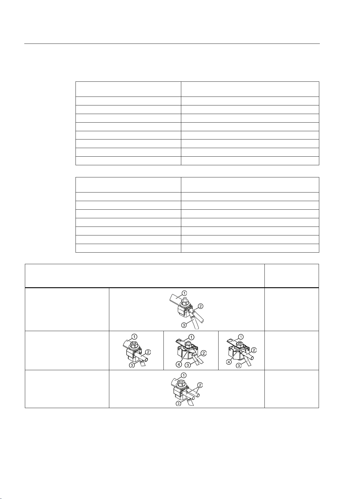
Electrical connection
Frame size
Max. connectable conductor cross-section
[mm²]
56 ... 112
4,0
132
6,0
160
16,0
180
10,0
180 (1LG4, 1LG6)
16,0
200 ... 225
50,0
250 ... 280
120,0
315
240,0
Frame size
Max. connectable conductor cross-section
[mm²]
71 ... 80
4,0
90 ... 160 M
6,0
160 L
16,0
180
25,0
200 ... 225
50,0
250 ... 280
120,0
6.3.2
Type of conductor connection
Terminal board
Conductor
crosssection
[mm²]
Connection with cable lug
①
②
③
④ Cover washer
6.3 Conductor connection
Table 6- 10 Max. conductor connection for explosion-proof machines (with the exception of Zone 22
and 1MJ) and VIK standard version
Table 6- 11 Max. conductor connection for standard 1MJ machines
DIN 46 234
Bend down the cable lug for the
connection!
Connection of an individual
conductor with terminal clamp
Connection of two conductors of
approximately the same
thickness with terminal clamp
Link rail
Power supply cord
Motor connection cable
315 240,0
... 25
... 10
... 25
Low-voltage motors
56 Operating Instructions, 05/2014, 5 610 00000 02 000
Page 57
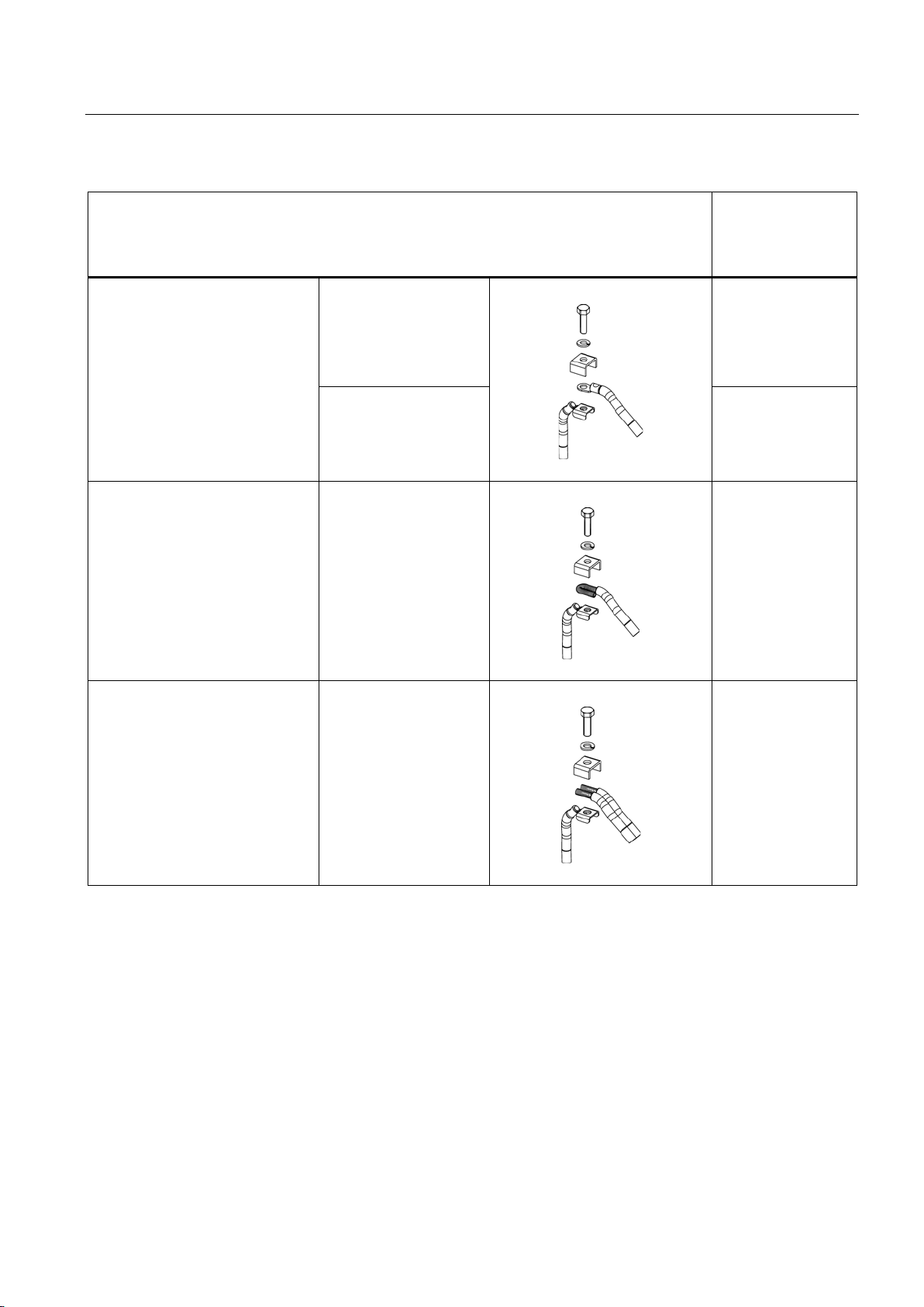
Electrical connection
Terminal plate
Conductor
cross-
section
[mm²]
6.3 Conductor connection
Bend down the cable lug for the
connection!
Connection of an individual
conductor with terminal clamp
Connection of two conductors of
the same thickness with terminal
clamp
1MA618.
1MA620.
1MA618. ... 20.
1MA618. ... 20.
… 10
… 35
… 25
… 25
Low-voltage motors
Operating Instructions, 05/2014, 5 610 00000 02 000
57
Page 58
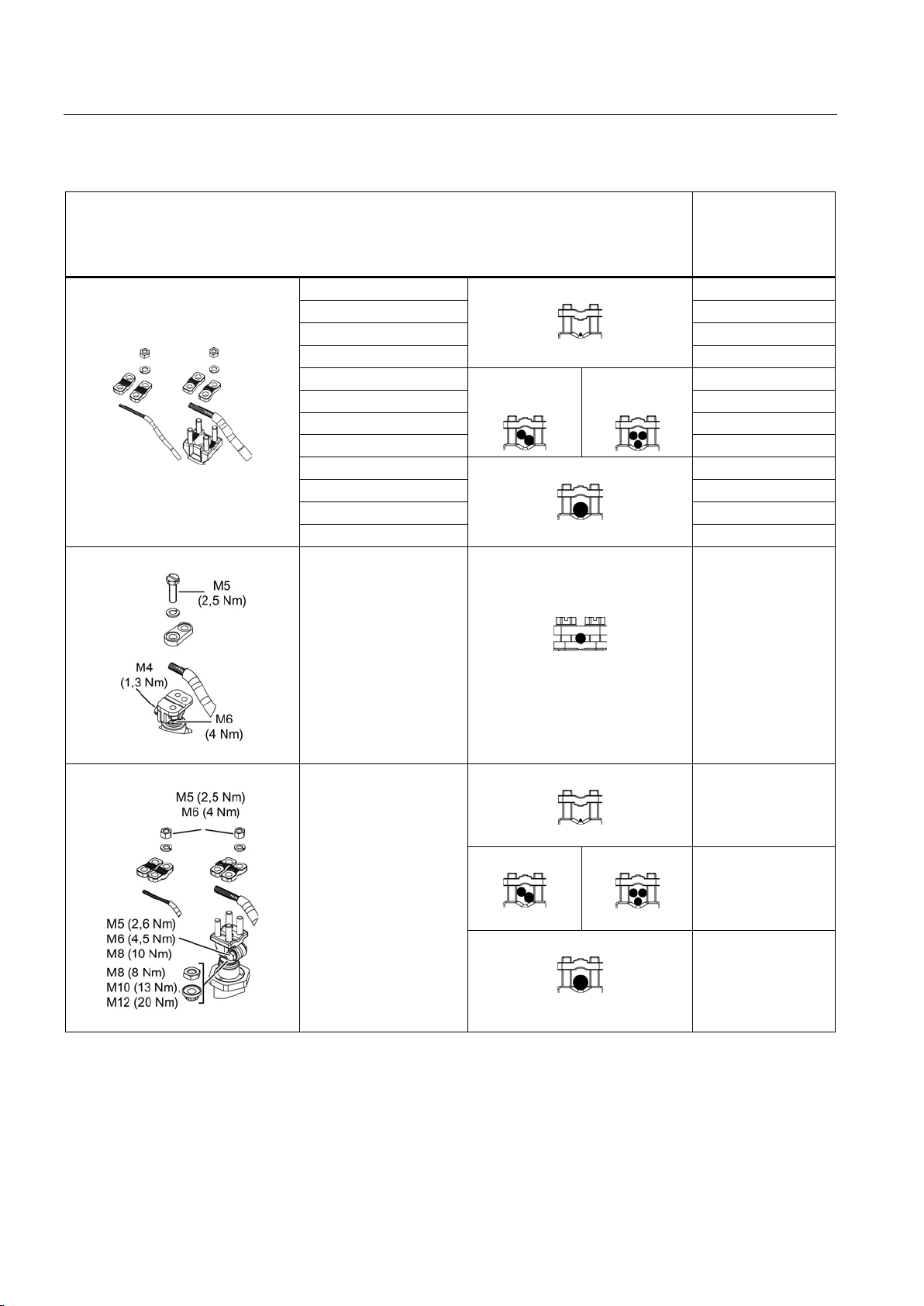
Electrical connection
Connecting terminal
Conductor
cross-
section
[mm²]
1MA618. ... 22.
2,5 … 25
1MA625. ... 28.
10 … 95
1MA631.
25 … 135
1MA631. + L00
50 … 300
1MA618. ... 22.
… 16
1MA625. ... 28.
… 35
1MA631.
… 70
1MA631. + L00
… 120
1MA618. ... 22.
16 … 50
1MA625. ... 28.
50 … 120
1MA631.
95 … 240
1MA631. + L00
120 … 400
6.3 Conductor connection
1MJ618.
2,5 ... 25
Low-voltage motors
58 Operating Instructions, 05/2014, 5 610 00000 02 000
1MJ62
2,5 ... 25
16
16 ... 50
Page 59
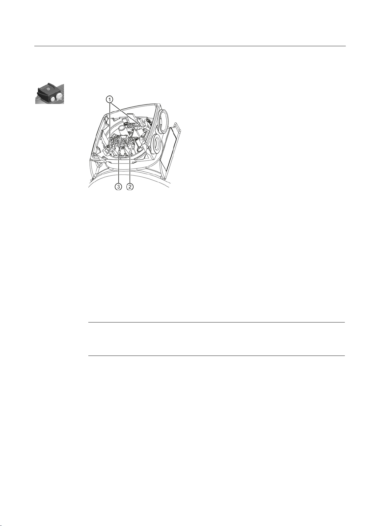
Electrical connection
Recommended connection variants
①
Cable lugs DIN 46237 with insulating sleeve (round and open)
②
Rigid cable (insulation removed at ends ≤ 8 mm)
③
End sleeves DIN 46228 ≤ 8 mm
alternative connection elements without insulating sleeve, for example cable lugs acc. to DIN 46234 .
6.4
Connecting the grounding conductor
6.4.1
General information on connecting the grounding conductor
Note
The machine's grounding conductor cross
Please also observe installation regulations such
6.4 Connecting the grounding conductor
If air gaps ≥ 5.5 mm (up to 690 V) are observed between non-insulated components, you can also use
-section must comply with EN / IEC 60034-1.
as those specified in EN / IEC 60204-1.
Basically, there are two ways of connecting a grounding conductor to the machine.
● Internal grounding with a connection in terminal box at the location intended for this
purpose and marked accordingly.
● External grounding with connection at the stator housing at the locations intended for this
purpose and marked accordingly.
Low-voltage motors
Operating Instructions, 05/2014, 5 610 00000 02 000
59
Page 60
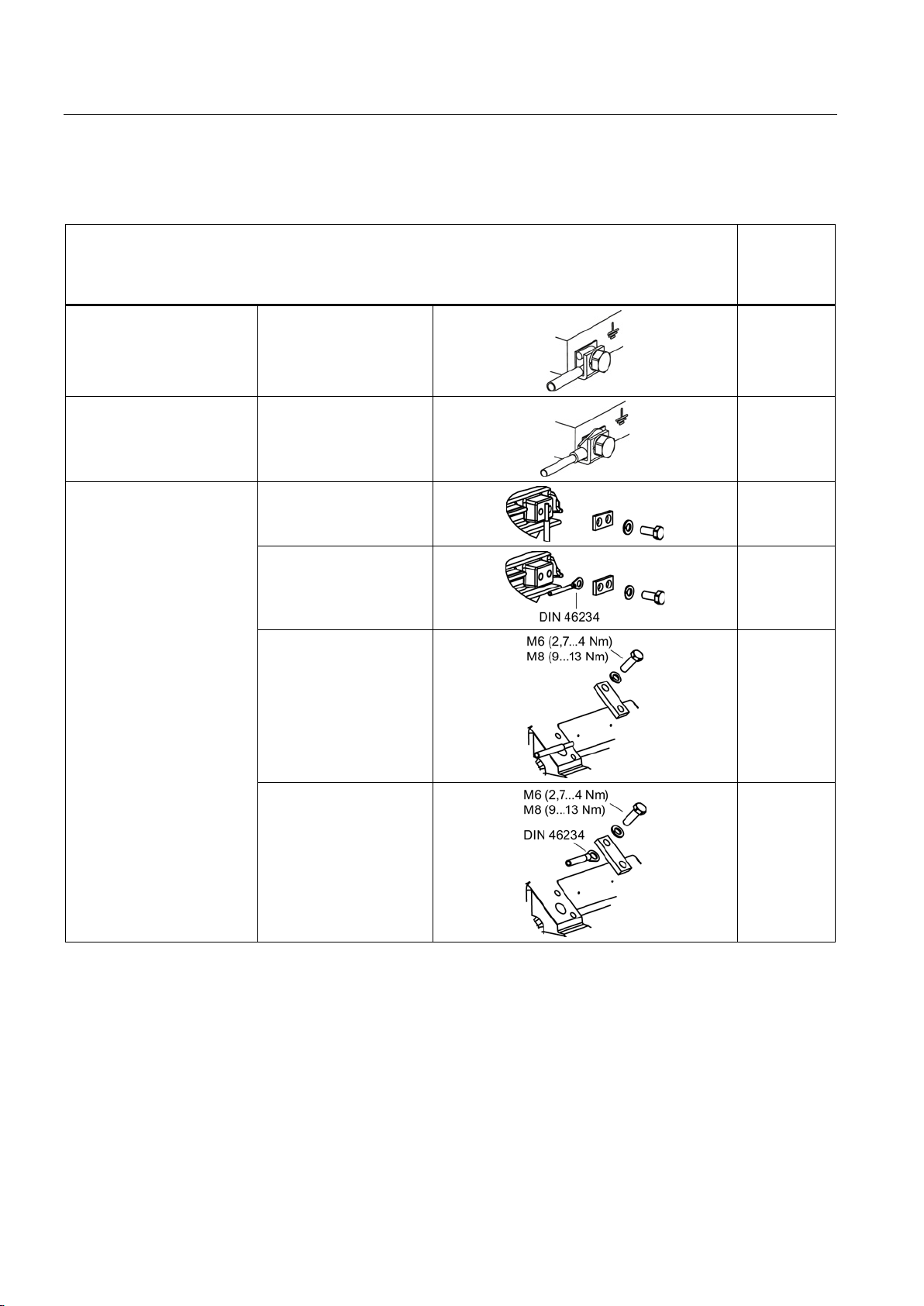
Electrical connection
6.4.2
Grounding connection type
Enclosure grounding method
Conductor
cross-
section
[mm²]
6.4 Connecting the grounding conductor
Connection of an individual
conductor under the external
grounding bracket.
Connection is made using a
DIN cable lug under the
external grounding bracket.
DIN 46 234
External grounding
1MJ6071 ... 132
1MJ618.
1MJ6160 L
… 10
… 25
... 25
... 35
.. 35
Low-voltage motors
60 Operating Instructions, 05/2014, 5 610 00000 02 000
1MJ620.
... 50
Page 61
Electrical connection
6.4.3
Minimum surface area of grounding conductor
Minimum cross-sectional area of phase
conductor for installation
S
[mm²]
Minimum surface area of associated grounding
connection
[mm²]
S ≤ 16
S
16 < S ≤ 35
16
S > 35
0.5 S
Internal ground terminal
External ground terminal
6.4 Connecting the grounding conductor
Table 6- 12 Minimum cross-sectional area of grounding conductor
When making connections, ensure the following:
● connecting surface is bare and is protected against corrosion using a suitable substance,
e.g. acid-free Vaseline.
● Locate the cable lug between the terminal clamps.
● Place a spring washer below the screw head.
When making connections, ensure the following:
● connecting surface is bare and is protected against corrosion using a suitable substance,
e.g. acid-free Vaseline.
● Position the cable lug between the contact bracket and the grounding bracket; do not
remove the contact bracket pressed into the enclosure!
● Place a spring washer below the screw head.
● Maintain the tightening torque of the terminal screw as specified in the table.
Low-voltage motors
Operating Instructions, 05/2014, 5 610 00000 02 000
61
Page 62
Electrical connection
6.4.4
Size of grounding conductor screw
external grounding
Frame size
Thread size for the grounding conductor
63 ... 90
M3.5 / M4
100 ... 112
M5
132 ... 180
M6
200 ... 225
M8
200 1LG4/6, 1LE1
2x M6
200 ... 315 1LG, 1LE1, 1MA
2x M8
For machines of size 80 ... 90 with central terminal
connected with a cable lug in accordance with DIN46237, size M4.
external grounding
Frame size
Thread size for the grounding conductor
71 ... 180
2x M6
200 ... 315
2x M8
6.5
Final measures
6.5 Final measures
Table 6- 13 Size of grounding conductor screw
Table 6- 14 Size of grounding conductor screw
-box locking, the ground conductor can also be
(except for 1MJ machines)
for 1MJ machines
Before closing the terminal box/terminal base of the machine enclosure, check the following:
● Establish the electrical connections in the terminal box in accordance with the details in
the sections above and tighten with the correct torque.
● The clearances between non-insulated parts have been maintained:
≥ 5.5 mm to 690 V, ≥ 8 mm to 1000 V.
● Avoid protruding wire ends!
● In order not to damage the cable insulation, freely arrange the connecting cables.
● Connect the machine corresponding to the specified direction of rotation.
● Keep the inside of the terminal box clean and free from trimmed-off ends of wire.
● Ensure that all seals and sealing surfaces are undamaged and clean.
● Correctly and professionally close unused openings in the terminal boxes.
Before closing the terminal box, check that
● the air clearances for explosion-protected machines (with the exception of machines for
Zone 22) between non-insulated parts are maintained: ≥ 10 mm to 690 V.
● the minimum creepage distance for explosion-protected machines (with the exception of
machines for Zone 22) between non-insulated parts is maintained: ≥ 12 mm to 690 V.
Low-voltage motors
62 Operating Instructions, 05/2014, 5 610 00000 02 000
Page 63
Electrical connection
6.6
Connecting optional mounted components
6.6.1
External fan, incremental encoder, brake
6.6.1.1
Mounting a brake
Frame size
(BG)
Brake type
Size assignment of the
brakes
Tightening torque of manual
lifting lever
Nm
80
2LM8 010–3NA10 1)
08
2.8
90
2LM8 020–4NA10 1)
10
4.8
100
2LM8 040–5NA10 1)
12
4.8
112
2LM8 060–6NA10 1)
14
12
132
2LM8 100–7NA10 1)
16
12
160
2LM8 260–8NA10 1)
20
23
180
2LM8 315–0NA10 1)
20
23
200
2LM8 400–0NA10 1)
25
40
225
2LM8 400–0NA10 1)
25
40
250
KFB 63 2)
63
40
280
KFB 100 2)
100
40
315
KFB 160 2)
160
40
1) INTORQ Corp.
2) PINTSCH BUBENZER Corp.
6.6.1.2
Mounted external fan
6.6 Connecting optional mounted components
See the list of additional operating instructions: Further documents (Page 116)
Select mounted components such as external fans, incremental encoders or brakes
according to the requirements of the directive 94/9/EG .
Table 6- 15 Assigning standard brakes for 1LE1 machines
Low-voltage motors
Operating Instructions, 05/2014, 5 610 00000 02 000
Tightening torque applied to the fastening screws used for attaching external fans to the
housing, see Terminal boxes, end shields, grounding conductors, sheet metal fan covers
(Page 54)
63
Page 64
Electrical connection
6.7
Connecting converters
NOTICE
Excessively high supply voltage
NOTICE
Missing shielding
WARNING
Machine overheating
Machines with increased safety "e" type of protection
Machines operated from a converter for Zone 21 and Zone 22
6.7 Connecting converters
Material damage can occur if the supply voltage is too high for the insulation system.
The standard insulation system is designed so that converter operation is possible for line
voltages up to U
≤ 500 V. Maintain the following limit values in all operating states (voltage
N
values are peak values):
Û
conductor-conductor
≤ 1500 V, Û
conductor-ground
≤ 1100 V, voltage rise times of ts > 0.1 µs.
• Machines must always be connected to converters using shielded machine feeder
cables.
• The most effective method of shielding is to conductively connect
the cable to the metal terminal box of the machine (with a metal screw connections)
through a large surface area.
• Please observe the section containing instructions on ensuring electromagnetic
compatibility (EMC).
See the list of additional operating instructions: Further documents (Page 116)
Operating explosion-protected machines at the converter without using the appropriate
protective equipment can result in death or severe injury.
Always use PTC thermistor monitoring when operating explosion-protected machines at the
converter. Tripping units according to directive 94/9/EC are always necessary when using
PTC thermistor monitoring.
Converter operation for these machines must be expressly certified. It is essential that you
observe the separate manufacturer's information and instructions. Converter and protective
devices must be marked as belonging together and the permitted operating data must be
defined in the common EC-type examination certificate.
These machines are generally equipped with three PTC thermistors in accordance with DIN
44082 with a rated response temperature that depends on the maximum possible surface
Low-voltage motors
temperature. Select the PTC thermistors in accordance with this standard. The maximum
64 Operating Instructions, 05/2014, 5 610 00000 02 000
Page 65

Electrical connection
System, converter-cable-electrical machine
Machines with type of protection flameproof enclosure "d" or "de"
Temperature sensors for tripping
Temperature sensors for alarm and trip
Mechanical limit speeds for converter operation
Motor-
frame size
Motor type
2-pole 1)
n
max
rpm
f
max
Hz
4-pole
n
max
rpm
f
max
Hz
6-pole
n
max
rpm
f
max
Hz
8-pole
n
max
rpm
f
max
Hz
1MJ6
71 M
1MJ6 07.
6000
100
3000
100
2000
100
1500
100
80 M
1MJ6 08 .
6000
100
3000
100
2000
100
1500
100
90 L
1MJ6 09 .
6000
100
3000
100
2000
100
1500
100
100 L
1MJ6 10 .
5400
90
3000
100
2000
100
1500
100
112 M
1MJ6 11 .
5400
90
3000
100
2000
100
1500
100
132 S/M
1MJ6 13 .
4800
80
3000
100
2000
100
1500
100
160 M/L
1MJ6 16 .
4500
75
3000
100
2000
100
1500
100
180 M/L
1MJ6 18 .
5100
85
3000
100
2000
100
1500
100
200 L
1MJ6 20 .
5100
85
3000
100
2000
100
1500
100
6.7 Connecting converters
temperature at the cable entries is 120° C. Use suitable cables for this temperature. Do not
exceed the maximum frequency dependent on the number of poles, which is stamped on the
rating plate.
Please observe the information in accordance with EN / IEC 60034-17 and EN / IEC 6003425 regarding winding stress. For line supplies with operating voltages up to 690 V, the
maximum value of the voltage peaks at the end of the cable must not exceed twice the value
of the converter's DC-link voltage.
These machines are equipped with three temperature sensors in the winding and one
temperature sensor in the gland plate in order that the temperature class is maintained.
Connect the temperature sensors in series according to the circuit diagram.
These machines have for warning and shutdown three temperature sensors in the winding
and one temperature sensor in the gland plate. Connect the temperature sensors in series
according to the circuit diagram.
Table 6- 16 Explosion-protected motors in Zone 1 with type of protection "de" (motor series 1MJ)
Low-voltage motors
Operating Instructions, 05/2014, 5 610 00000 02 000
65
Page 66

Electrical connection
Motor-
frame size
Motor type
2-pole 1)
n
max
rpm
f
max
Hz
4-
pole
n
max
rpm
f
max
Hz
6-pole
n
max
rpm
f
max
Hz
8-pole
n
max
rpm
f
max
Hz
1LA5, 1LA6, 1LA7, 1LA9
56 M
1LA7/1LA9
05.
6000
100
3000
100
2000
100
1500
100
63 M
1LA7/1LA9
06.
6000
100
3000
100
2000
100
1500
100
71 M
1LA7/1LA9
07.
6000
100
3000
100
2000
100
1500
100
80 M
1LA7/1LA9
08.
6000
100
3000
100
2000
100
1500
100
90 L
1LA7/1LA9
09.
6000
100
3000
100
2000
100
1500
100
100 L
1LA6/1LA7/1LA9
10.
5400
90
3000
100
2000
100
1500
100
112 M
1LA6/1LA7/1LA9
11.
5400
90
3000
100
2000
100
1500
100
132 S/M
1LA6/1LA7/1LA9
13.
4800
80
3000
100
2000
100
1500
100
160 M/L
1LA6/1LA7/1LA9
16.
4500
75
3000
100
2000
100
1500
100
180 M/L
1LA5/1LA9
18.
5100
85
3000
100
2000
100
1500
100
200 L
1LA5/1LA9
20.
5100
85
3000
100
2000
100
1500
100
225 S/M
1LA5
22.
5100 4)
85 4)
3000
100
2000
100
1500
100
1LG4, 1LG6
180 M/L
1LG4/1LG6
18.
4500
75
3000
100
2000
100
1500
100
200 L
1LG4/1LG6
20.
4500
75
3000
100
2000
100
1500
100
225 S/M
1LG4/1LG6
22.
4500
75
3000
100
2000
100
1500
100
250 M
1LG4/1LG6
25.
3900
65
3000
100
2000
100
1500
100
280 S/M
1LG4/1LG6
28.
3600
60
3000
100
2000
100
1500
100
315 S/M/L
1LG4/1LG6
31.
3600 1)
60 1)
2600
87
2000
87
1500
100
1)
2)
3)
4)
The values in the following table are used for explosion-protected motors with option D19
Frame size
N
max
rpm
f
max
Hz
180 M/L
3300
55
200 L
3100
51
225 S/M
3000
50
6.7 Connecting converters
Table 6- 17 Explosion-proof motors in Zones 2, 21 and 22 with type of protection "n" or protection against dust explosions
(motor series 1LA, 1LG)
3) 4)
3) 4)
For continuous operation in the range f
For vertical mounting n
= 3000 rpm, f
max
(n
max
= 50 Hz.
max
max
For 1LA9 motors, frame sizes 180 M/L and 200 L, n
3) 4)
3) 4)
), an inquiry is required.
= 4500 min-1 and f
max
= 75 Hz.
max
Low-voltage motors
66 Operating Instructions, 05/2014, 5 610 00000 02 000
Page 67
7
7.1
Insulation resistance
7.1.1
Testing the insulation resistance
WARNING
Hazardous voltage at the terminals
NOTICE
Short-circuit
Note
If the critical insulation resistance is less than or equal to this value, the windings must be
dried or, if the fan is removed, cleaned thoroughly and dried.
Please note that the insulation resistance of dried, clean windings is lower than that of warm
w
reference temperature of 25
Note
If the measured value is close to the critical value, you must check the insulation resistance
at suitably frequent intervals.
Only appropriately trained personnel may carry out this work.
Hazardous voltages are sometimes present at the terminals during and immediately after
measurement of the winding insulation resistance. If you touch the terminals, this can result
in death, serious injury or material damage.
If any power cables are connected, check to make sure line supply voltage cannot be
connected. To discharge the winding, after measuring the insulation resistance, connect the
winding to ground potential.
Material damage can occur if you do not apply the following measures:
• Check the insulation resistance before commissioning and after any extended periods of
storage or periods during which the equipment is not operational.
• Before measuring the insulation resistance, read the operating manual for the insulation
resistance meter you are going to use.
• Disconnect any connected main-circuit cables from the terminals before measuring the
insulation resistance.
indings. The insulation resistance can only be properly assessed after conversion to the
°C.
Low-voltage motors
Operating Instructions, 05/2014, 5 610 00000 02 000
67
Page 68
Commissioning
Measuring the insulation resistance
Limit values of the stator winding insulation resistance
Measuring circuit voltage
500 V
repaired windings
Critical specific insulation resistance after a long operating
time
7.1 Insulation resistance
1. Before you begin measuring the insulation resistance, please read the operating manual
for the insulation resistance meter you are going to use.
2. Disconnect any connected main-circuit cables from the terminals before measuring the
insulation resistance.
3. Where possible, measure the insulation resistance of the winding with respect to the
motor enclosure when the winding temperature is between 20 ... 30 °C. Different
insulation resistance values apply for other temperatures.
4. When measuring, wait until the final resistance value is reached. This is reached after
approximately one minute. Then read off the insulation resistance.
The following table indicates the measuring circuit voltage and the limit values for the
minimum insulation resistance and the critical insulation resistance of the stator winding.
Table 7- 1 Insulation resistance of the stator unwinding at 25 °C
Minimum insulation resistance for new, cleaned or
10 MΩ
0,5 MΩ / kV
Note the following:
● If the measurements are performed at winding temperatures ≠ 25 °C, convert the
measured value to the reference temperature of 25 °C in order to be able to compare the
values with the table above.
– The insulation resistance halves every time the temperature rises by 10 K.
– The resistance doubles every time the temperature falls by 10 K.
● Dry, new windings have a typical insulation resistance of more than 100 ... 2000 MΩ
depending on the winding size, design and rated voltage. An insulation resistance value
close to the minimum value could be due to moisture and/or dirt accumulation.
● During operation, the insulation resistance of the windings can fall to the critical insulation
resistance due to ambient and operational influences. The critical insulation resistance
value for a winding temperature of 25 °C can be calculated by multiplying the rated
voltage (kV) by the specific critical resistance value (0,5 MΩ / kV).
Low-voltage motors
68 Operating Instructions, 05/2014, 5 610 00000 02 000
Page 69
Commissioning
Example:
NOTICE
Critical insulation resistance reached or fallen below
See also
7.2
Measures before start-up
WARNING
Rotating parts
NOTICE
Damage caused by insufficient cooling
7.2 Measures before start-up
Critical resistance for UN = 690 V rated voltage:
690 V x 0,5 MΩ / kV = 0,345 MΩ
If the critical insulation resistance is reached or fallen below, this can result in damage to
the insulation or voltage flashovers.
• Contact your Siemens Service Center.
• If the measured value is close to the critical value, you must check the insulation
resistance at suitably frequent intervals.
SIEMENS Service Center (Page 115)
Electrical machines contain dangerous rotating parts. Fatal or severe injuries and
substantial material damage can occur if the required covers are removed or if the
machines are not handled, operated, or maintained properly.
Before commissioning, attach the covers that prevent inadvertently touching active and
rotating components.
Effective cooling is no longer possible if air guidance of the machine is not provided as
intended. This can damage the machine.
Before commissioning, attach the covers in order to guarantee the required air guidance.
Low-voltage motors
Operating Instructions, 05/2014, 5 610 00000 02 000
69
Page 70

Commissioning
Measures
7.2 Measures before start-up
Once the system has been correctly installed, you should check the following prior to
commissioning:
● The machine has been assembled and aligned correctly.
● The machine has been connected so that it rotates in the direction specified.
● The operating conditions match the data specified on the rating plate.
● The bearings have been lubricated as appropriate for the version used. Rolling-contact
bearing machines which have been in storage for more than 24 months have been
relubricated.
● Any supplementary machine monitoring equipment has been connected correctly and is
functioning as it should.
● For versions with bearing thermometers, the bearing temperatures must be checked
during the machine's first period of operation. The warning and shutdown values are set
on the monitoring device.
● Appropriately configured control and speed monitoring functions ensure that the machine
cannot exceed the permissible speeds specified on the rating plate.
● The output elements have the correct settings for their type (e.g. alignment and balancing
of couplings, belt forces in the case of a belt drive, tooth forces and tooth face clearance
in the case of toothed-wheel power output, radial and axial clearance in the case of
coupled shafts).
● The minimum insulation resistance and minimum clearance values have been adhered
to.
● The grounding and equipotential bonding connections have been established correctly.
● All fixing screws, connection elements, and electrical connections have been tightened to
the specified torques.
● Lifting eyes that were screwed in have been removed following installation or secured to
prevent them becoming loose.
● The rotor can turn without coming into contact with the stator.
● All touch protection measures for both moving and live parts have been implemented.
● In cases where the shaft extension is not being used and is, therefore, exposed, it has
been covered and the feather key has been secured to prevent it from being thrown out.
● If being used, the external fan is ready for operation and connected so that it rotates in
the direction specified.
● The flow of cooling air is not obstructed.
● If a brake is being used, it is functioning correctly.
● The specified mechanical limit speed n
Low-voltage motors
is adhered to.
max
70 Operating Instructions, 05/2014, 5 610 00000 02 000
Page 71

Commissioning
Note
It may be necessary to per
situation on site.
7.3
Switching on
Measures for start-up
7.3 Switching on
If the design of the machine requires the converter to be assigned in a particular way, the
relevant information will be provided on the rating plate or an additional label.
form additional checks and tests in accordance with the specific
After installation or inspections, the following measures are recommended for normal startup of the machines:
● Start the machine without a load; to do this, close the motor starter protector and do not
switch the machine off prematurely. You should limit how often you switch the machine
off while it is starting up and still running at a slow speed, for checking the direction of
rotation or the required dimensions, for example. Allow the machine to run to a standstill
before switching it back on again.
● Check the mechanical operation for noises or vibrations at the bearings and bearing end
shields.
● If the motor does not run smoothly and/or there are any abnormal noises, switch it off and
determine the cause as it slows down.
● If mechanical operation improves immediately after the machine is switched off, then the
cause is magnetic or electrical. If mechanical operation does not improve immediately
after switching the machine off, then the cause is mechanical, such as an imbalance in
the electrical machines or in the driven machine, inadequate alignment of the machine
set, operation of the machine with the system resonating (system = machine + base
frame + foundation, etc.).
● If there are no problems with the machine's mechanical operation, switch on any cooling
devices that are being used and continue to monitor the machine for a while during noload operation.
Low-voltage motors
Operating Instructions, 05/2014, 5 610 00000 02 000
71
Page 72
Commissioning
NOTICE
Damage to the motor
Measures to take when commissioning explosion-proof machines
7.3 Switching on
● If it runs perfectly, connect a load. Check that it runs smoothly, and read off and
document the values for voltage, current and power. As far as possible, read off and
document the corresponding values for the driven machine as well.
If you do not maintain the permissible vibration values, this can either damage or
destroy the motor.
In operation, maintain the permissible vibration values according to ISO 10816.
● Monitor and document the temperatures of the bearings, windings, etc. until the system
reaches a steady state, in as much as this is possible with the available measuring
instruments.
After installation or inspections, the following measures are recommended for normal startup of the machines:
● Start the machine without a load; to do this, close the motor starter protector and do not
switch the machine off prematurely.
● You should limit how often you switch the machine off while it is starting up and still
running at a slow speed, for checking the direction of rotation or the required dimensions,
for example.
● Allow machines to reach a standstill before switching them back on.
Low-voltage motors
72 Operating Instructions, 05/2014, 5 610 00000 02 000
Page 73
8
8.1
Safety instructions
8.1.1
Safety instructions during operation
Switching on the machine with anti-condensation heating (optional)
CAUTION
Machine overheating
Machine operation
DANGER
Hazardous voltages
WARNING
Rotating or live parts
– Covers required to maintain the degree of protection of the machine.
Slight injury or material damage can occur if you do not observe the following:
Switch off the (optional) anti-condensation heating before switching on.
Operating the machine on a line supply system with a non-grounded neutral point is only
permitted over short time intervals that occur rarely, e.g. the time leading to a fault being
eliminated (ground fault of a cable, EN / IEC 60034-1).
Rotating or live parts are dangerous. Death, serious injury, or material damage can result if
the required covers are removed.
• De-energize the machine and bring it into a no voltage condition before removing any
covers.
• Ensure that the following covers are closed in operation:
– Covers that prevent coming into contact with active or rotating parts
– Covers that are required for the correct air guidance, and therefore for effective
cooling
Low-voltage motors
Operating Instructions, 05/2014, 5 610 00000 02 000
73
Page 74
Operation
WARNING
Risk of burning
NOTICE
Premature bearing failure
WARNING
Faults during operation
specific safety
NOTICE
Risk of corrosion due to condensation
8.1 Safety instructions
Electrical machines have hot surfaces. Fatal or severe injuries and substantial material
damage can occur if the required covers are removed or if the machines are not handled,
operated, or maintained properly.
Do not touch the machine in operation and wait until the machine has completely cooled
down.
The bearings can be damaged if the following is not observed.
Be sure to comply with the minimum radial load of 30% of the cylindrical roller bearings in
accordance with catalog data.
Changes with respect to normal operation indicate that there is an impaired function. This
can cause faults which can result in eventual or immediate death, severe injury or material
damage.
For instance, observe the following signs that could indicate a malfunction:
• Higher power drawn than usual
• Higher temperatures than usual
• Unusual noises
• Unusual smells
• Activation of monitoring equipment
Immediately contact the maintenance personnel if you identify any irregularities If you are in
doubt, immediately switch off the machine, being sure to observe the systemconditions.
When changing machines and/or ambient temperatures, air humidity can condense within
the machines.
• If available, remove the screw plugs to drain the water depending on the ambient and
operating conditions.
• Reinsert them afterwards.
If the motor is equipped with drain plugs, then the water can drain away automatically.
Low-voltage motors
74 Operating Instructions, 05/2014, 5 610 00000 02 000
Page 75
Operation
CAUTION
Risk of injury when touching the fan
8.1.2
Safety information for explosion-protected machines in operation
WARNING
Explosion hazard
8.1 Safety instructions
There is a risk of injury at machines equipped with a fan cover for the textile industry, as the
fan is not completely touch protected.
• Do not touch the rotating fan.
• Do not put your fingers into the larger air discharge openings.
• Manual intervention must be prevented on the customer's side by using suitable
measures, e.g. appropriate housings or a protective grating.
These explosion-protected machines are not suitable for hybrid explosive environments.
This can result in death, serious injury or material damage.
Use in atmospheres where there is a risk of explosion caused by both gas and dust
simultaneously is absolutely prohibited.
Only install machines with type of protection flameproof enclosure "d", increased safety "e",
and machines for Zone 2 in hazardous areas, according to the regulations laid down by the
responsible supervisory authority. They are responsible for determining the hazard level of
each area (division into zones). Layers of dust on machines for Zone 21 and Zone 22 must –
under no circumstances – be higher than 5 mm.
● If there are no other specifications in the EC-type examination certificate or on the rating
plate regarding operating mode and tolerance, electrical machines are designed for
continuous duty and normal startup procedures that are performed infrequently and do
not result in excessive temperature rise. Only use these machines for the operating mode
specified on the rating plate.
● Measures for maintaining the temperature class:
For S1 line supply operation, a function-tested, current-dependent protective device that
monitors all three phase conductors provides sufficient protection for the machine. This
protective device is set to the rated current and must switch off machines with 1.2x the
rated current within 2 hours or less. Do not switchoff for 1.05-fold or smaller rated current.
Pole-changing machines require a separate switch for each number of poles. If an anticondensation heating system is available, it may only be switched on when the machines
are not in operation.
For S2 to S9 line supply operation, machines with type of protection Flameproof
Enclosure "d" must be equipped with at least three temperature sensors (one per phase),
a temperature sensor in the gland plate and with a suitable electronic switchoff device
with a temperature sensor.
Low-voltage motors
Operating Instructions, 05/2014, 5 610 00000 02 000
75
Page 76
Operation
8.1.3
Safety instructions for cleaning
Cleaning
WARNING
Explosion hazard
8.1.4
Machines with textile fan covers
8.2
Stoppages
Overview
NOTICE
Restricted motor function
8.2 Stoppages
To ensure problem-free machine cooling, the air ducts (ventilation grilles, channels, cooling
fins, tubes) must be free of pollution.
It is forbidden to clean the machine in an explosive atmosphere. This can result in death,
serious injury or material damage.
Surfaces can become statically charged and discharge to ignite potentially explosive
atmospheres.
In order to guarantee an essentially unobstructed flow of cooling air containing fluff, remains
of materials or similar dirt, machines with a fan cover for textile applications have a larger air
discharge cross-section between the edge of the cover and the cooling ribs of the machine
frame.
These machines have a warning sticker on the fan cover.
If the machine remains out of service for an extended period of time (> 1 month), it should be
commissioned regularly (around once a month) or, at the very least, the rotor should be
turned. Please refer to the instructions in the section titled "Switching on" before
recommissioning the machine. If a rotor locking device has been fitted to the machine, you
must remove it before the rotor starts to turn.
Low-voltage motors
76 Operating Instructions, 05/2014, 5 610 00000 02 000
If not used for longer periods of time, material damage or complete motor failure can occur.
If the motor is out of service for a period of more than 12 months, then environmental
effects can damage the motor.
Apply suitable corrosion protection, preservation, packing and drying measures.
Page 77

Operation
Switching on the anti-condensation heater
Taking the machine out of service
Lubricating before recommissioning
NOTICE
Dry running bearings
8.2 Stoppages
If an anti-condensation heater is provided, switch it on during the machine stoppages.
For details of measures that need to be implemented, please refer to Section Preparing for
use (Page 27).
Bearings can be damaged if they do not have sufficient grease.
Re-grease the bearings if they have been out of service for more than one year. The shaft
must rotate so that the grease can be distributed in the bearings. Observe the data on the
lubricant plate.
See also Chapter, Maintenance - bearing service life.
Low-voltage motors
Operating Instructions, 05/2014, 5 610 00000 02 000
77
Page 78
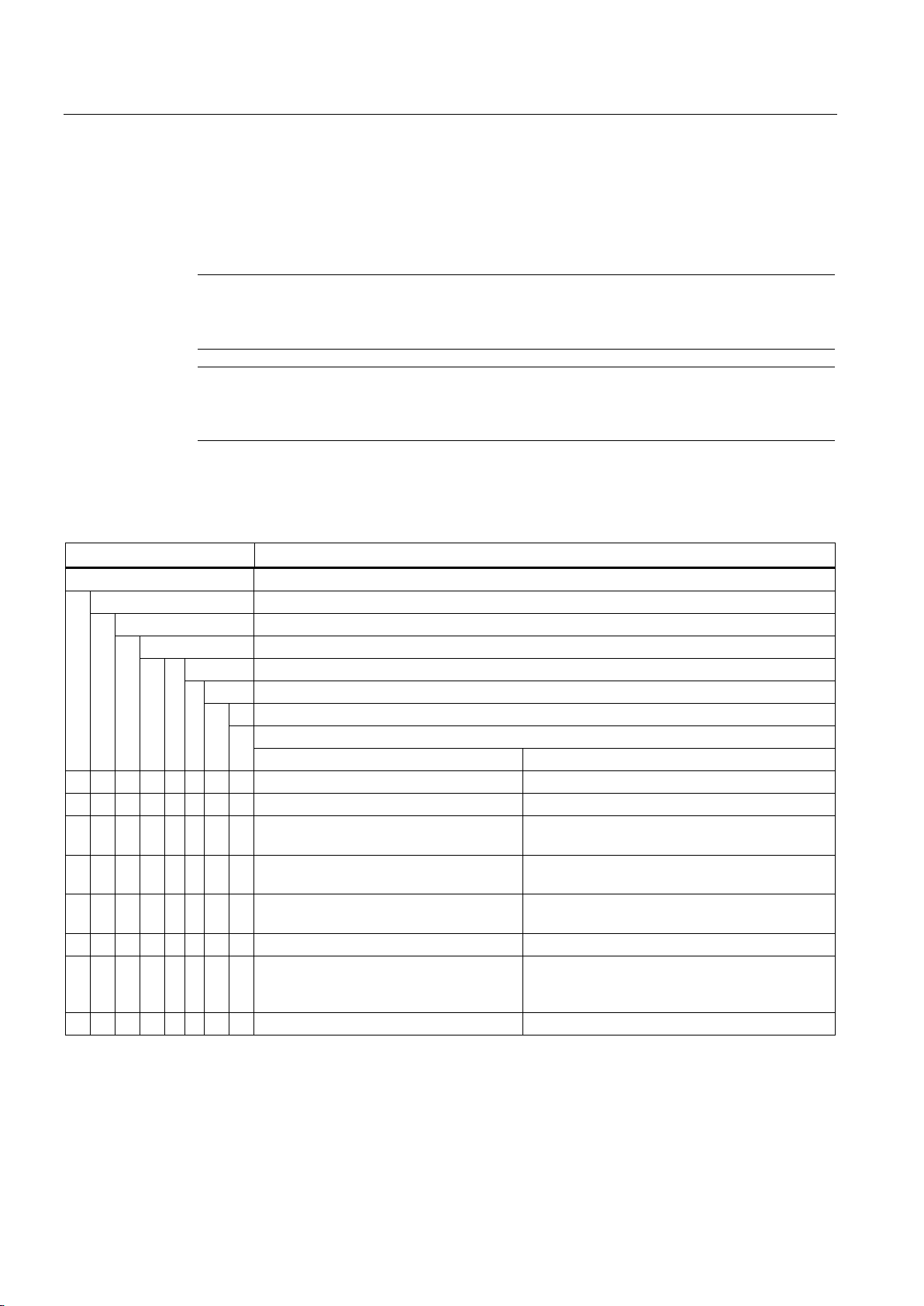
Operation
8.3
Fault tables
Note
Before removing any faults, please read the information in Chapter
(Page
Note
If you operate the motor with a converter, and an electrical fault occurs, then also observe
the information in the c
Electrical fault characteristics
↓
Machine will not start up
↓
Machine starts up reluctantly
↓
Rumbling noise during operation
↓
Overheating during no-load operation
↓
Overheating when under load
↓
Overheating of individual winding sections
Possible causes of faults
Remedial measures
X X X X Overload
Reduce load
X Interruption of a phase in the supply line
Check switches and supply lines
after switching on
high
low
X X X X X Stator winding incorrectly connected
Check winding connections
manufacturer
X Incorrect direction of rotation of axial fan
Check connections
8.3 Fault tables
Safety information
11).
onverter operating instructions.
The tables below list general faults caused by mechanical and electrical influences.
Table 8- 1 Electrical influences
↓ Rumbling noise during startup
X X X X X Interruption of a phase in the supply line
X X Supply voltage too low, frequency too
X Supply voltage too high, frequency too
X X X X Winding short circuit or phase short
circuit in stator winding
1)
Check switches and supply lines
Check power supply conditions
Check power supply conditions
Measure the winding resistances and insulation
resistances, repair after consultation with
(1) As well as eliminating the cause of the fault (as described under "Remedial measures"),
you must also rectify any damage the machine may have suffered.
Low-voltage motors
78 Operating Instructions, 05/2014, 5 610 00000 02 000
Page 79
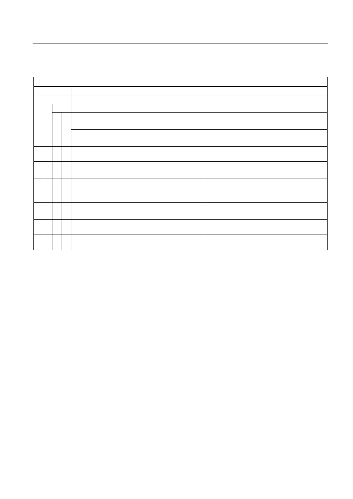
Operation
Mechanical fault characteristics
↓
Grinding noise
↓
Overheating
↓
Radial vibrations
↓
Axial vibrations
Possible causes of faults
Remedial measures1)
X Rotating parts are grinding
Determine cause and adjust parts concerned
direction
X Rotor not balanced.
Check feather key declaration (H, F, N)
X Rotor out of true, shaft bent
Please consult the manufacturer.
check coupling. 2)
X Coupled machine not balanced
Re-balance coupled machine
X Surges from coupled machine
Inspect coupled machine
X X Imbalance originating from gearing
Adjust/repair gearing
necessary; realign machine
8.3 Fault tables
Table 8- 2 Mechanical effects
X Reduced air supply, fan possibly rotating in the wrong
X X Poor alignment Align machine set,
X X Resonance in the overall system (comprising machine
and foundation)
X X Changes in foundation Determine cause of changes; eliminate if
Check airways, clean machine
Reinforce foundation following consultation
1) As well as eliminating the cause of the fault (as described under "Remedial measures"),
you must also rectify any damage the machine may have suffered.
2) Note any changes that take place while the temperature is rising.
Low-voltage motors
Operating Instructions, 05/2014, 5 610 00000 02 000
79
Page 80
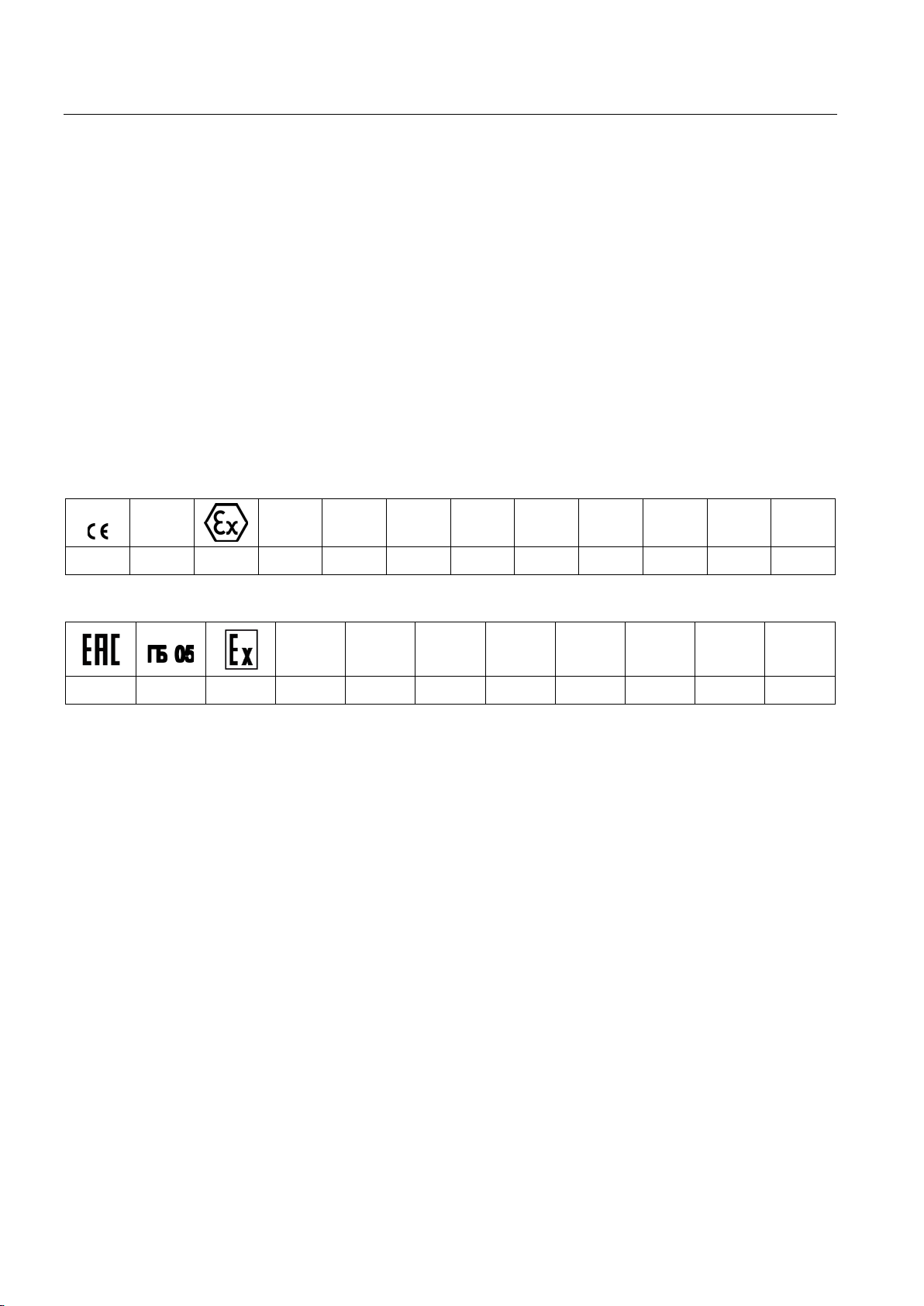
Operation
8.4
Deactivating
8.5
Class
8.5.1
Zone 1 with type of protection Ex de IIC Gb (flameproof enclosure "d" for the machine and increased safety "e" for the terminal box)
158
II
2
G
Ex
d
e
IIC
T4
Gb
① ② ③ ④ ⑤ ⑥ ⑦ ⑧ ⑨ ⑩ ⑪ ⑫
1
Ex
d
e
IIC
T4
Gb
X
① ② ③ ⑬ ⑦ ⑧ ⑨ ⑩ ⑪ ⑫ ⑭
①
CE
②
Identification number or name of nominated testing agency
③
Code for prevention of explosions
④
Device group: II not fo
⑤
Device category: 2 for occasional danger and for use in Zone 1
⑥
Atmosphere: G for gas
⑦
Explosion protection: International
⑧
Type of protection: "d" Flameproof Enclosure of machine
⑨
Type of protection: "e" Inc
Explosion group: IIC for acetylene
⑪
Temperature class: T4 for maximum surface temperature of 135° C
Device protection level: Gb for a high level of protection in hazardous zones with
explosive gas mixtures
⑬
Zone 1
⑭
"X" special conditions
8.4 Deactivating
Commission any devices provided for protection against condensation after switching off the
machine.
- or EAC marking
r mining, but other hazardous zones
⑩
reased Safety of terminal box
⑫
Low-voltage motors
80 Operating Instructions, 05/2014, 5 610 00000 02 000
Page 81
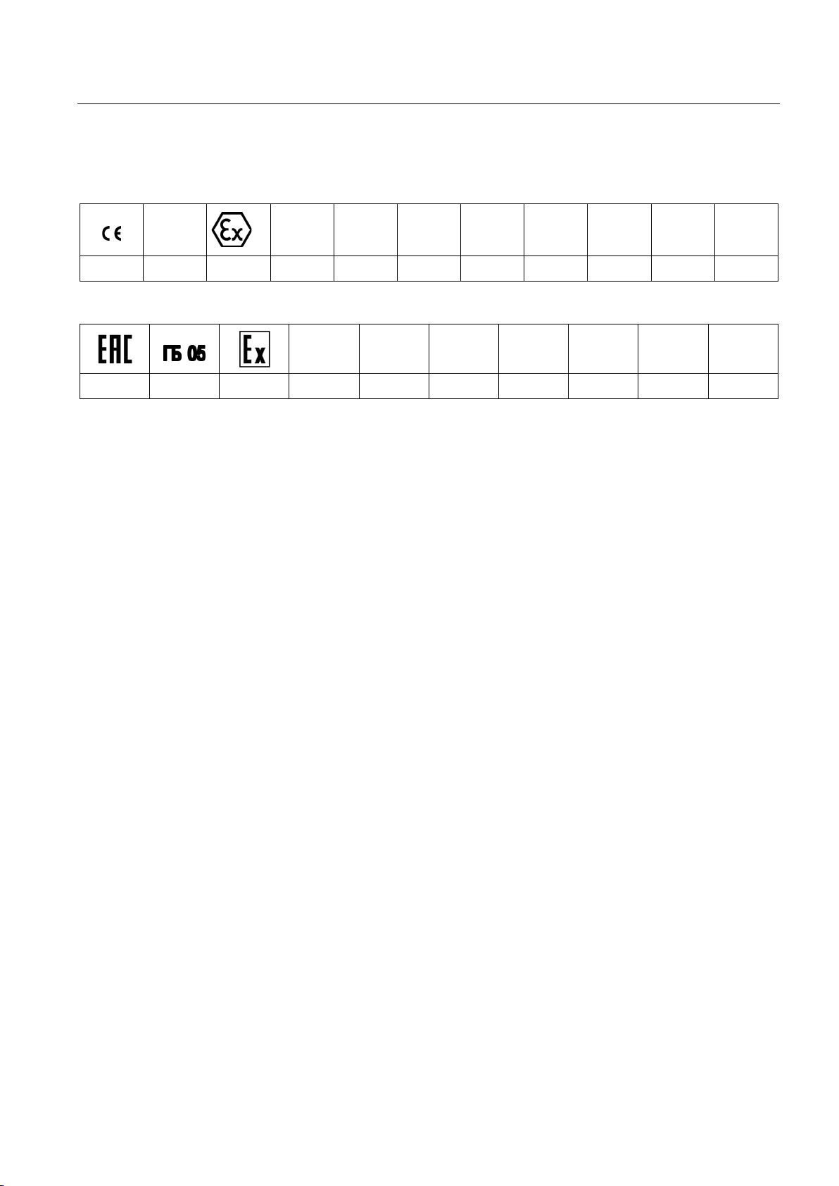
Operation
8.5.2
Zone 1 with Ex e IIC Gb type of protection (increased safety "e")
158
II
2
G
Ex
e
IIC
T3
Gb
① ② ③ ④ ⑤ ⑥ ⑦ ⑧ ⑨ ⑩ ⑪
1
Ex
e
IIC
T3
Gb
X
① ② ③ ⑫ ⑦ ⑧ ⑨ ⑩ ⑪ ⑬
①
CE
②
Identification number or name of nominated testing agency
③
Code for prevention of explosions
④
Device group: II not for minin
⑤
Device category: 2 for occasional danger
⑥
Atmosphere: G for gas
Explosion protection: International
⑧
Type of protection: "e" Increased Safety
⑨
Explosion group: IIC for acetylene
Temperature class: T3 for maximum
⑪
Device protection level: Gb for a high level of protection in hazardous zones with
explosive gas mixtures
Zone 1
⑬
"X" special conditions
8.5 Class
- or EAC marking
⑦
⑩
⑫
g, but other hazardous zones
surface temperature of 200° C
Low-voltage motors
Operating Instructions, 05/2014, 5 610 00000 02 000
81
Page 82
Operation
8.5.3
Zone 1 with Ex e IIB Gb type of protection (increased safety "e")
158
II
2
G
Ex
e
IIB
T3
Gb
① ② ③ ④ ⑤ ⑥ ⑦ ⑧ ⑨ ⑩ ⑪
1
Ex
e
IIB
T3
Gb
X
① ② ③ ⑫ ⑦ ⑧ ⑨ ⑩ ⑪ ⑬
①
CE
②
Identification number or name of nominated testing agency
③
Code for prevention of explosions
④
Device group: II not for mining, but other hazardous zones
⑤
Device category: 2 for occasional danger
⑥
Atmo
Explosion protection: International
⑧
Type of protection: "e" Increased Safety
⑨
Explosion group: IIB for ethylene
Temperature Class: T3 for maximum surface temperature of 200° C
⑪
Device protection level: Gb for a high level of
explosive gas mixtures
Zone 1
⑬
"X" special conditions
8.5 Class
- or EAC marking
⑦
⑩
⑫
sphere: G for gas
protection in hazardous zones with
Low-voltage motors
82 Operating Instructions, 05/2014, 5 610 00000 02 000
Page 83
Operation
8.5.4
Zone 2 with type of protection Ex nA IIC Gc, non sparking
II
3
G
Ex
nA
IIC
T3
Gc
① ② ③ ④ ⑤ ⑥ ⑦ ⑧ ⑨ ⑩
2
Ex
nA
IIC
T3
Gc
X
① ⑪ ② ⑫ ⑥ ⑦ ⑧ ⑨ ⑩ ⑬
①
CE
②
Code for pr
③
Device group: II not for mining, but other hazardous zones
④
Device category: 3 for infrequent, short
⑤
Atmosphere: G for gas
⑥
Explosion protection: International
Type of protection: "nA" for non
⑧
Exp
⑨
Temperature Class: T3 for maximum surface temperature of 200° C
Device protection level: Gc for an extended level of protection in hazardous zones with
explosive gas mixtures
⑪
Identification number or name of nominat
Zone 2
⑬
"X" special conditions
8.5 Class
- or EAC marking
evention of explosions
⑦
⑩
⑫
losion group: IIC for acetylene
-term danger
-sparking
ed testing agency
Low-voltage motors
Operating Instructions, 05/2014, 5 610 00000 02 000
83
Page 84
Operation
8.5.5
Zone 2 with type of protection Ex nA IIB Gc, non sparking
II
3
G
Ex
nA
IIB
T3
Gc
① ② ③ ④ ⑤ ⑥ ⑦ ⑧ ⑨ ⑩
2
Ex
nA
IIB
T3
Gc
X
① ⑪ ② ⑫ ⑥ ⑦ ⑧ ⑨ ⑩ ⑬
①
CE
②
Code for prevention of explosions
③
Device group:
④
Device category: 3 for infrequent, short
⑤
Atmosphere: G for gas
⑥
Explosion protection: International
Type of protection: "nA" for non
⑧
Explosion group: IIB for ethylene
⑨
Temper
Device protection level: Gc for an extended level of protection in hazardous zones with
explosive gas mixtures
⑪
Identification number or name of nominated testing agency
Zone 2
⑬
"X" specia
8.5 Class
- or EAC marking
⑦
⑩
⑫
II not for mining, but other hazardous zones
-term danger
-sparking
ature Class: T3 for maximum surface temperature of 200° C
l conditions
Low-voltage motors
84 Operating Instructions, 05/2014, 5 610 00000 02 000
Page 85
Operation
8.5.6
Zone 21
158
II
2
D
Ex
tb
IIIC
T125°C
Db
① ② ③ ④ ⑤ ⑥ ⑦ ⑧ ⑨ ⑩ ⑪
Ex
tb
IIIC
T125°C
Db
X
① ② ③ ⑦ ⑧ ⑨ ⑩ ⑪ ⑫
①
CE
②
Identification number or name of nominated testing agency
③
Code for prevention of explosions
④
Device group: II not for mining,
⑤
Device category: 2 for occasional danger
⑥
Atmosphere: D for dust
Explosion protection: International
⑧
Type of protection: "tb" for protection by enclosure
⑨
Explosion group: IIIC for conductive dust
Maximum surface
⑪
Device protection level: Db for a high level of protection level in flammable dust
atmospheres
"X" special conditions
8.5 Class
- or EAC marking
⑦
⑩
⑫
but other hazardous zones
temperature: T 125° C
Low-voltage motors
Operating Instructions, 05/2014, 5 610 00000 02 000
85
Page 86
Operation
8.5.7
Zone 22
II
3
D
Ex
tc
IIIB
T125°C
Dc
① ② ③ ④ ⑤ ⑥ ⑦ ⑧ ⑨ ⑩
Ex
tc
IIIB
T125°C
Dc
X
① ⑪ ② ⑥ ⑦ ⑧ ⑨ ⑩ ⑫
①
CE
②
Code
③
Device group: II not for mining, but other hazardous zones
④
Device category: 3 for infrequent, short
⑤
Atmosphere: D for dust
⑥
Explosion protection: International
Type of protection: "tc" for protection
⑧
Explosion group: IIIB for non
⑨
Maximum surface temperature: T 125° C
Device protection level: Dc for an extended protection level in flammable dust
atmospheres
⑪
Identification number or name of nominated testing agenc
"X" special conditions
8.5 Class
- or EAC marking
for prevention of explosions
-term danger
⑦
by enclosure
-conductive dust
⑩
y
⑫
Low-voltage motors
86 Operating Instructions, 05/2014, 5 610 00000 02 000
Page 87
9
9.1
Preparation and notes
WARNING
Hazards when carrying out maintenance work
Note
For operating conditions, which deviate from the conditions specified on the rating plate, the
general maintenance intervals specified up until now can cha
Preparation and notes for explosion-protected machines
You must observe the following safety instructions to prevent death, injury or material
damage:
• Before starting work on the machines, make sure that the plant or system has been
disconnected in a manner that is compliant with the appropriate specifications and
regulations.
• In addition to the main circuits, make sure that supplementary and auxiliary circuits,
particularly in heating devices, are also disconnected.
• Certain parts of the motor may reach temperatures above 50° C. Physical contact with
the machine could result in burn injuries! Check the temperature of parts before
touching them.
• When using compressed air for cleaning, make sure that appropriate methods of
extraction systems are in place and that personal protective gear is worn (protective
goggles, face mask and similar).
• If you are using chemical cleaning agents, observe the instructions and any warnings
provided in the relevant safety data sheet. Chemical agents must be compatible with the
machine's components, especially if these contain plastics.
● Only have the machines repaired in authorized Siemens workshops!
● For machines intended for use in hazardous areas, only have modifications, repairs and
overhaul work carried out by appropriately qualified personnel.
Low-voltage motors
Operating Instructions, 05/2014, 5 610 00000 02 000
It is imperative that you observe the regulations according to EN / IEC 60079-19 !
● When making changes or performing repair or overhauling work on machines intended
for use with combustible dust, please observe the regulations laid down by
EN / IEC 60079-17!
nge.
87
Page 88
Maintenance
9.1.1
North American market
Machines for the North American market (optional)
Underwriters Laboratories
Canadian Standard Association
Canadian Standard Association Energy Efficiency Verification
9.1.2
Customs union Eurasia
Machines Eurasian market (optional)
Customs union Eurasia
Eurasian customs union
Explosion
9.1 Preparation and notes
When making changes or repairs, maintain the corresponding design standards! These
machines are labeled on the rating plate with the following markings.
Table 9- 1 Markings for the North American market
When making changes or repairs, maintain the corresponding design standards! These
machines are labeled on the rating plate with the following markings.
-protected
Low-voltage motors
88 Operating Instructions, 05/2014, 5 610 00000 02 000
Page 89
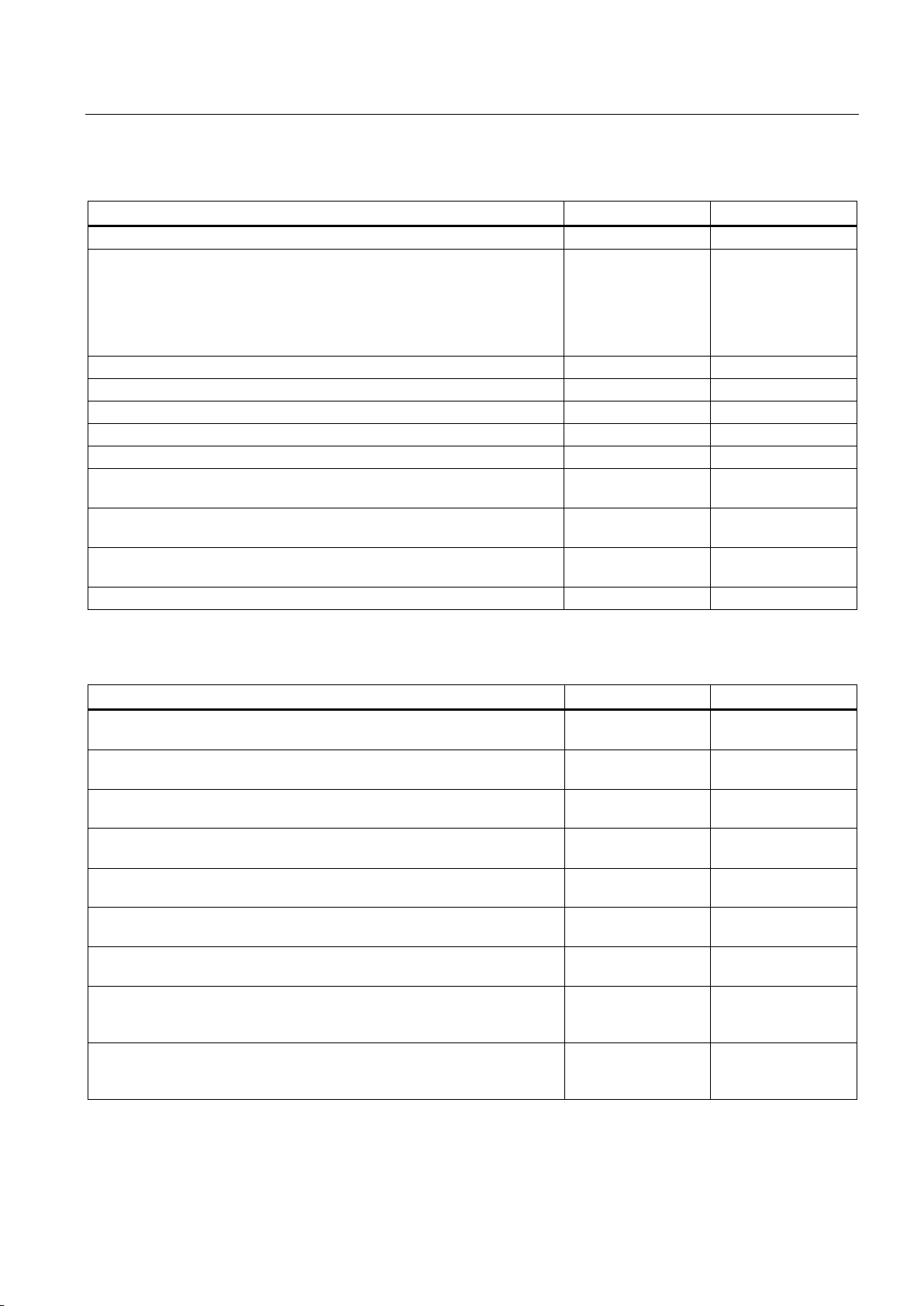
Maintenance
Feature
Standard
EAC
Dimensioning and operating behavior
EN / IEC 60034-1
GOST R IEC 60034-1
Procedure for determining the losses and the efficiency of rotating electrical
2-3
Degree of protection
EN / IEC 60034-5
GOST R IEC 60034-5
Cooling
EN / IEC 60034-6
GOST R IEC 60034-6
Type of construction
EN / IEC 60034-7
GOST R IEC 60034-7
Terminal designations and direction of rotation
EN / IEC 60034-8
GOST R IEC 60034-8
Noise emission
EN / IEC 60034-9
GOST R IEC 60034-9
12
30
Feature
Standard
EAC
requirements
2002
enclosure "d"
2002
safety "e"
2002
installations for endangered atmospheres (except underground excavation)
2002
protection "n"
2002
overhauls
2002
protection by enclosure "t"
31
(except underground excavation)
hazardous areas.
9.1 Preparation and notes
Table 9- 2 Applicable general regulations
machines and inspections
EN / IEC 60034-2-1
EN / IEC 60034-2-2
EN / IEC 60034-2-3
GOST R IEC 60034-
2-1
GOST R IEC 60034-
2-2
GOST RIEC 60034-
Starting characteristics of rotating electrical machines EN / IEC 60034-12 GOST R IEC 60034-
Vibration severity grades EN / IEC 60034-14 GOST R IEC 60034-
14
Efficiency classification of three-phase squirrel-cage induction motors EN / IEC 60034-30 GOST R IEC 60034-
IEC standard voltages IEC 60038 GOST R IEC 60038
Table 9- 3 Regulations applied for explosion-protected machines
Electrical equipment for hazardous gas atmospheres, Part 0: General
Electrical equipment for hazardous gas atmospheres, Part 1: Flameproof
Electrical equipment for hazardous gas atmospheres, Part 7: Increased
Electrical equipment for hazardous gas atmospheres, Part 14: Electric
Electrical equipment for hazardous gas atmospheres, Part 15: Type of
Electrical equipment for hazardous gas atmospheres, Part 19: Repairs and
Potentially explosive atmosphere - Part 31: Device dust explosion
Electrical equipment for use in the presence of combustible dust - Part 17:
Inspection and maintenance of electrical systems in hazardous areas
Directive on the approximation of the laws of the Member States
concerning equipment and protective systems intended for use in
EN / IEC 60079-0 GOST 30852 0 -
EN / IEC 60079-1 GOST 30852 1 -
EN / IEC 60079-7 GOST 30852 8 -
EN / IEC 60079-14 GOST 30852 13 -
EN / IEC 60079-15 GOST 30852 14 -
EN / IEC 60079-19 GOST 30852 18 -
EN / IEC 60079-31 GOST R IEC 60079-
EN / IEC 60079-17 GOST 30852 16 -
2002
RL94/9/EC TR CU
Low-voltage motors
Operating Instructions, 05/2014, 5 610 00000 02 000
89
Page 90
Maintenance
9.1.3
Touch up any damaged paintwork
Note
Paint system
Contact the Service
more information about the correct paint system and methods of repairing paint damage.
9.1.4
Repainting
WARNING
Explosion danger caused by incorrect painting
9.1 Preparation and notes
If the paint is damaged, it must be repaired in order to protect the unit against corrosion.
Center before you repair any paint damage. They will provide you with
If the paint coat thickness exceeds the permissible thickness, then electrostatic discharge
can occur and associated discharge. At this instant, if there is any explosive mixture that
can be easily ignited, then an explosion can occur resulting in death, severe injury and
material damage.
When repainting/touching up, avoid excessively thick paint coatings. You can determine the
permissible coating thickness of the paint depending on the explosion group and the
surface resistance of the paint.
You must comply with one of the following requirements when you repaint painted surfaces:
● Limit the total paint coating thickness in accordance with the explosion protection group:
– IIA, IIB: Total paint coating thickness ≤ 2 mm
– IIC: Total paint coating thickness ≤ 0.330 mm for motors of group II (gas)
● Limit the surface resistance of the paint used:
– IIA, IIB, IIC, III: Surface resistance ≤ 1 GΩ for machines of groups II and III (gas and
dust)
● Breakdown voltage ≤ 4 kV for explosion group III (dust only)
● An overall coating thickness of > 120 µm is inadmissible for processes which generate
strong charges.
Low-voltage motors
90 Operating Instructions, 05/2014, 5 610 00000 02 000
Page 91

Maintenance
9.2
Inspection
9.2.1
General inspection specifications
Notes
Note
Pay particular attention to the relubrication intervals for rolling bearings that deviate from the
inspection intervals.
Note
When servicing a three
machine only has to be dismantled if the bearings are to be replaced.
9.2.2
Optional built-on accessories
See also
9.2.3
Initial inspection
Inspection interval
Procedure
9.2 Inspection
-phase machine, it is generally not necessary to dismantle it. The
See the list of additional operating instructions: Auto-Hotspot
Further documents (Page 116)
The first inspection after installation or repair of the three-phase machine is, under normal
circumstances, conducted after approx. 500 operating hours, but at the latest after 1/2 year.
Check the following points while the motor is operational:
● Maintain the electrical parameters.
● Comply with the permissible bearing temperatures.
● The smooth running characteristics and noise of the three-phase machine must not
deteriorate.
Check the following points while the motor is at a standstill:
Low-voltage motors
Operating Instructions, 05/2014, 5 610 00000 02 000
91
Page 92

Maintenance
Note
Additional checks and tests may be required. Observe the as
instructions and special plant/system
Note
Rectify any impermissible deviations immediately.
9.2.4
Main inspection
Inspection interval
Procedure
Note
Rectify any impermissible deviations immediately.
9.2 Inspection
● The motor foundation must have no indentations or cracks.
sociated supplementary
-specific conditions
Inspect the machine once a year.
Check the following points while the motor is operational:
● Maintain the electrical parameters.
● Comply with the permissible bearing temperatures.
● The smooth running characteristics and noise of the three-phase machine must not
deteriorate.
Check the following points while the motor is at a standstill:
● The motor foundation must have no indentations or cracks.
● The three-phase machine must be aligned within the permissible tolerances.
● All of the mounting bolts for the mechanical and electrical connections must be securely
tightened.
● The winding isolation resistances must be sufficiently high.
● Cables and insulating parts and components must be in a good condition and must not be
discolored.
Low-voltage motors
92 Operating Instructions, 05/2014, 5 610 00000 02 000
Page 93
Maintenance
9.3
Maintenance
9.3.1
Maintenance intervals
CAUTION
Skin irritations and eye inflammations
NOTICE
Motor failure
Measures
Operating period intervals
Intervals
Initial inspection
After 500 operating hours
After 1/2 year at the latest
Relubrication (optional)
See the lubricant plate
Clean
Depending on the degree of pollution
Drain condensate
Depending on the climatic conditions
9.3 Maintenance
Many greases can cause skin irritations and eye inflammations.
Follow all safety instructions of the manufacturer.
The machines are equipped with permanently lubricated roller bearings. A regreasing device
is optional.
Carry out careful and regular maintenance, inspections, and revisions to detect faults at an
early stage and eliminate them before they can cause further damage.
Operating situations and characteristics can vary widely. For this reason, only general
maintenance intervals can be specified here. Maintenance intervals should therefore be
scheduled to suit the local conditions (dirt, starting frequency, load, etc.).
Material damage can occur if the motor develops faults or is overloaded.
If faults occur, immediately carry out an inspection. An immediate inspection is especially
necessary, if the three-phase motor is excessively stressed, either electrically or
mechanically (e.g. overload or short-circuit).
Measures, intervals
Measures after operating period intervals have elapsed:
Table 9- 4 Operating period intervals
Main inspection Approximately every 16000 operating
Low-voltage motors
Operating Instructions, 05/2014, 5 610 00000 02 000
After two years at the latest
hours
93
Page 94

Maintenance
9.3.2
Regreasing (optional)
Note
It is not permissible to mix different types of grease.
Procedure
9.3.3
Cleaning
Cleaning the greasing channels and used grease chambers
Note
You have to separate the active parts of the bearings to replace the grease that is in the
greasing channel.
9.3 Maintenance
For machines with regreasing system, relubrication intervals, grease quantity and grease
grade are provided on the lubricant plate. Additional data can be taken from the main
machine rating plate.
Grade of grease for standard motors (IP55) UNIREX N3 - ESSO).
Prolonged storage periods reduce the useful lifetime of the bearing grease. Check the
condition of the grease if the equipment has been in storage for more than 12 months. If the
grease is found to have lost oil content or to be contaminated, the machine must be
immediately relubricated before commissioning. For information on permanently-greased
bearings, please refer to the section titled Storage (Page 96).
To relubricate the roller bearings, proceed as follows:
1. Clean the grease nipples at the drive end and non-drive end.
2. Press in the type and quantity of grease specified (see rating/lubricant plate data).
– Please observe the information on the rating and lubricant plates.
– Regreasing should be carried out when the motor is running (max. 3600 rpm).
The bearing temperature rises sharply at first, then drops to the normal value again when the
excess grease is displaced out of the bearing.
The used grease collects outside each bearing in the used grease chamber of the outer
bearing cap. When replacing bearings, remove the used grease.
Low-voltage motors
94 Operating Instructions, 05/2014, 5 610 00000 02 000
Page 95
Maintenance
Cleaning the cooling air passages
Note
Never direct compressed air in the direction of the shaft outlet or machine openings.
Note
The frequency of the cleaning intervals depends on the local degree of contamination.
WARNING
Damage to the motor
See also
9.3.4
Drain condensate
NOTICE
Reduction of the degree of protection
9.3 Maintenance
Regularly clean the cooling air passages through which the ambient air flows, e.g. using dry
compressed air.
In the case of machines with textile fan covers, regularly remove fluff balls, fabric remnants,
and similar types of contamination (particularly at the air passage opening between the fan
cover and cooling fins of the machine enclosure) to ensure that the cooling air can flow
without obstruction.
Material damage can occur if you direct compressed air towards the shaft outlet or
openings in the motor.
Avoid directly pointing compressed air onto shaft sealing rings or labyrinth seals of the
motor.
Safety instructions for cleaning (Page 76)
If there are condensate drain holes present, these must be opened at regular intervals,
depending on climatic conditions.
If condensation drain holes are not closed, then this can result in material damage to the
motor.
In order to maintain the degree of protection, after the condensation has been drained, all
of the drain holes must be closed again.
Low-voltage motors
Operating Instructions, 05/2014, 5 610 00000 02 000
95
Page 96
Maintenance
9.4
Corrective maintenance
9.4.1
Instructions for repair
Qualified personnel
Instructions relevant to safety
WARNING
High voltages
Note
Observe the information in Chapter Preparing for use.
See also
9.4.2
Storage
Bearing lifetime
9.4 Corrective maintenance
Only appropriately qualified persons should be deployed to commission and operate
equipment. Qualified persons, as far as the safety instructions specified in this manual are
concerned, are those who have the necessary authorization to commission, ground and
identify/tag equipment, systems and circuits in accordance with the relevant safety
standards.
Electrical machines contain live parts. Fatal or severe injuries and substantial material
damage can occur if the required covers are removed or if the machines are not handled,
operated, or maintained properly.
Before starting to work on the motor, bring it into a no voltage condition, and only open the
covers of active parts once this has been done.
Preparing for use (Page 27)
Take the bearing used up to frame size 90 only for special versions, and generally for frame
size 100 and higher from the rating plate.
Prolonged storage periods reduce the useful lifetime of the bearing grease. In the case of
permanently lubricated bearings, this leads to a shorter bearing lifetime.
Bearing or grease replacement is recommended after a storage time of 12 months, for
longer than four years, replace the bearings or grease.
Low-voltage motors
96 Operating Instructions, 05/2014, 5 610 00000 02 000
Page 97
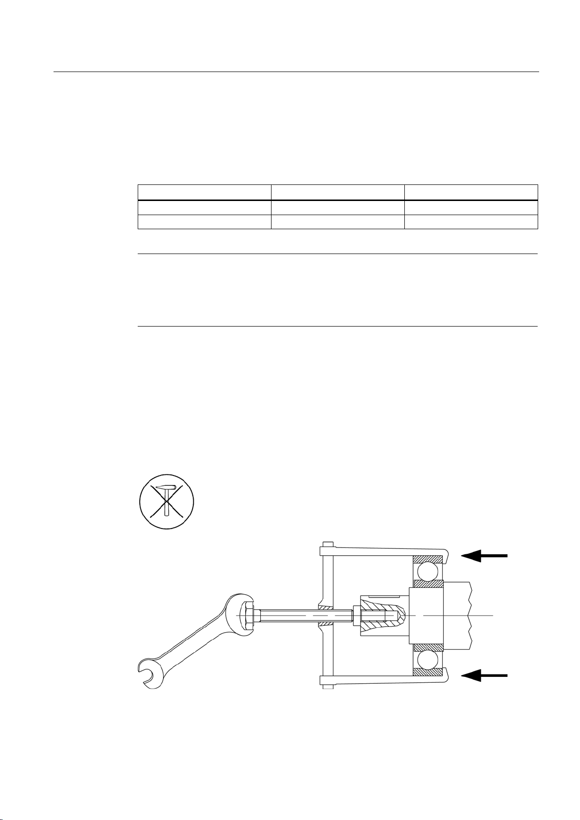
Maintenance
Replacing bearings
Ambient temperature
Principle of operation
Bearing replacement intervals
40° C
Horizontal coupling operation
40 000 h
40° C
With axial and radial forces
20 000 h
Note
Special operating conditions
Examples of factors that can reduce operatin
vibrational and impact loads, frequent reversing, higher ambient temperature, higher speeds,
etc.
9.4.2.1
Changing bearings
Replacing bearings
9.4 Corrective maintenance
Recommended interval after which bearings are to be replaced under normal operating
conditions:
Table 9- 5 Bearing replacement intervals
g hours are vertical machine installation, high
● Do not reuse bearings that have been removed.
● Remove any polluted old grease from the bearing shield.
● Replace old grease with new grease.
● Replace the shaft seals when the bearings are replaced.
● Lightly grease the contact surfaces of the sealing lips!
Low-voltage motors
Operating Instructions, 05/2014, 5 610 00000 02 000
97
Page 98
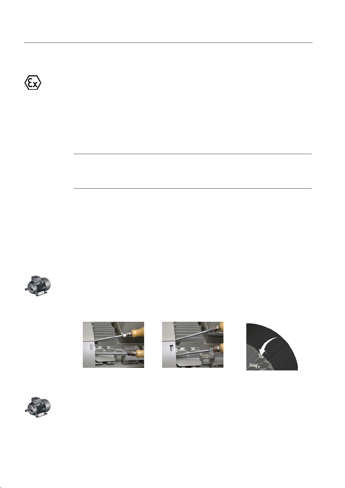
Maintenance
9.4.2.2
Replacing bearings in explosion-proof machines
9.4.3
Dismantling
Note
Before commencing disassembly, you should mark
been assigned, as well as how internal connections are arranged. This simplifies subsequent
reassembly.
Fan
Fan cover
Canopy; incremental encoder under the canopy
9.4 Corrective maintenance
● When changing the bearings, renew the sealing rings and only use original Siemens
spare parts.
● When installing the sealing rings for the motor series 1LA., 1MA.06. to 20., 1MJ6., fill
completely the space in the sealing ring and in the end shield hub with a suitable type of
grease.
how each of the fastening elements has
Take care not to damage the snapping mechanisms on fans that are equipped with these.
To ensure this, the fans should be heated to a temperature of approximately 50 °C around
the area of the hub. If any damage is caused, request new parts.
● Carefully lever the snap openings on the cover out of the snap-in lugs one after the other;
do not apply the lever directly under the web (risk of breakage).
● Do not damage the snap mechanisms. If any damage is caused, request new parts.
Loosen the fixing screws on the external surface of the protective cover.
Under no circumstances should the spacing bolts or the mounting bracket be disassembled
or forcibly separated from each other or the cover. Forcibly removing or separating can
destroy the distance bolts, the connecting elements of the mounting bracket or the fan cover.
Low-voltage motors
98 Operating Instructions, 05/2014, 5 610 00000 02 000
Page 99
Maintenance
9.4.3.1
Bearing bushes
9.4.3.2
Links
9.4.4
Assembly
9.4.4.1
Assemly
See also
9.4.4.2
Fitting the bearing cartridges
9.4 Corrective maintenance
Protect the bearings against the ingress of dirt and moisture.
● Replace any corroded screws.
● Take care not to damage the insulation of live parts.
● Document the position of any rating and supplementary plates that have been removed.
● Avoid damaging the centering edges.
If possible, assemble the machine on and alignment plate. This ensures that the mounting
feet surfaces are all on the same plane.
Avoid damaging the windings protruding out of the stator enclosure when fitting the end
shield.
● Apply Fluid-D to the centering edge.
● Check the terminal box seals, and if required, replace these.
● Repair any damage to the paint, also to screws/bolts.
● Take the necessary measures to ensure compliance with the applicable degree of
protection.
● Do not forget the foam rubber cover in the cable entry. Completely seal the holes, and
ensure that cables do not come into contact with sharp edges.
Terminal boxes, end shields, grounding conductors, sheet metal fan covers (Page 103)
For flameproof machines, apply just a small amount of acid-free, non-resinous grease to the
centering edges (e.g. Renolit H 442 supplied by Fuchs). Do not use any sealing agents.
When fitting the bearing cartridges, observe the specified screw tightening torques.
Low-voltage motors
Operating Instructions, 05/2014, 5 610 00000 02 000
99
Page 100
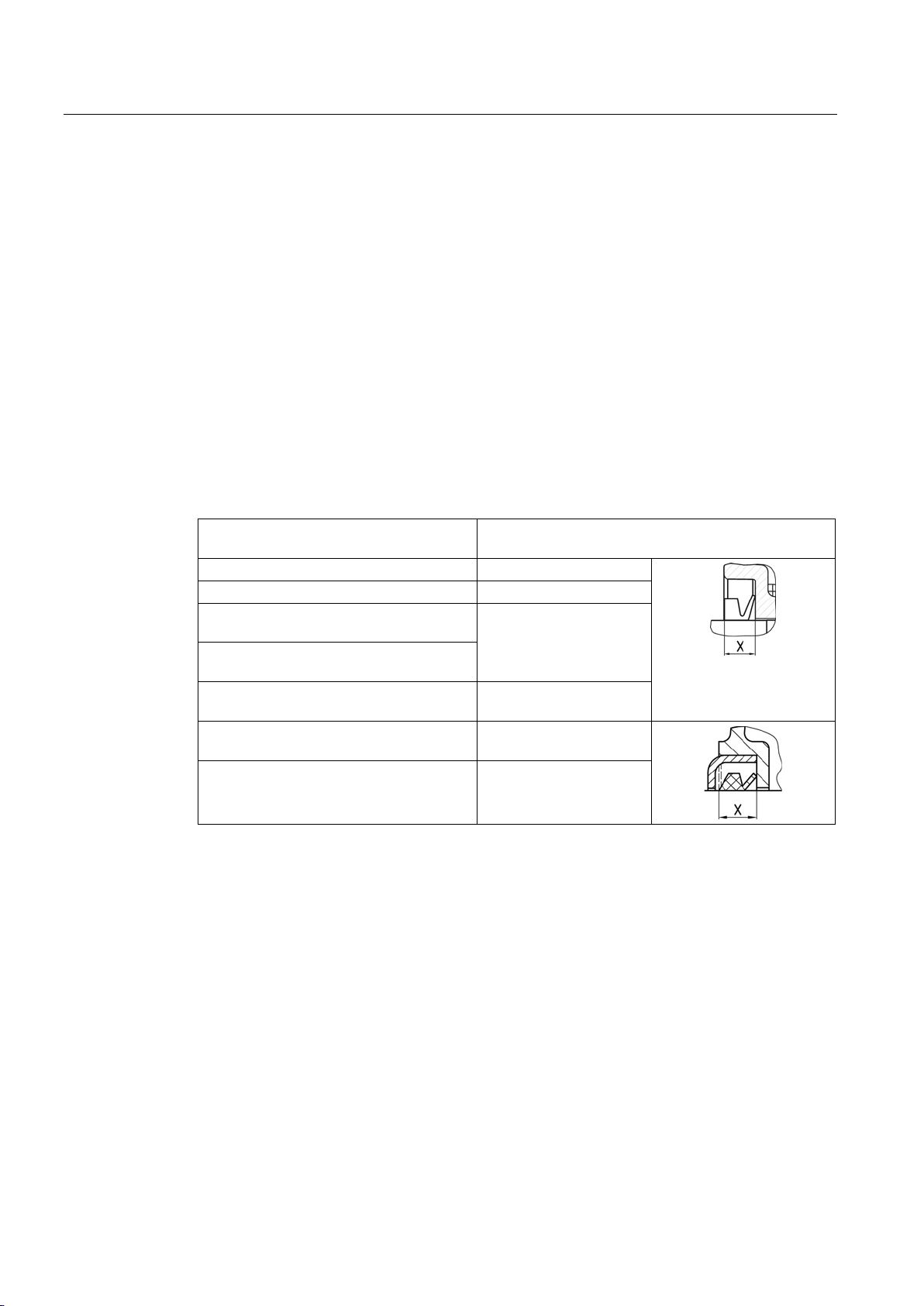
Maintenance
9.4.4.3
Fitting bearings
Sealing the bearings
Mounting dimension "x" of V rings
Frame size X
[mm]
100 ... 112
6 ±0.8 132 ... 225
7 ±1
(1LG, 1MA622.)
(1LG, 1LE; 4 ... 8-pole)
(1LG, 1LE; 4 ... 8-pole)
(1LG, 1LE; 2-pole)
9.4.4.4
Mounting fans
Fans
9.4 Corrective maintenance
Note the following details:
● Shaft sealing rings are used to seal machines at the rotor shaft. For V rings, comply with
the assembly dimension.
● Use the specified bearings.
● Ensure that the bearing sealing disks are in the correct position.
● Insert the elements for bearing preloading at the correct end.
● Fixed bearings can have a locking ring or bearing cover.
180 ... 225
11 ±1
225
250 ... 315
225
250 ... 315
(1LG, 1LE; 2-pole)
13.5 ±1.2
11 ±1
13.5 ±1.2
Take care not to damage the snapping mechanisms on fans that are equipped with these.
To ensure this, the fans should be heated to a temperature of approximately 50 °C around
the area of the hub.
If any damage is caused, request new parts.
Low-voltage motors
100 Operating Instructions, 05/2014, 5 610 00000 02 000
 Loading...