

Siemens SIMOTICS FD 1MH1, SIMOTICS FD 1MQ1, SIMOTICS FD 1LL1 Operating Instructions & Installation Instructions
Page 1
www.siemens.com/drives
For employment in zone 2 (IEC/EN 60079-10-1)
Operating Instructions
Installation Instructions
Low-voltage motor
SIMOTICS FD
Type 1MH1
II 3G Ex ec IIC T3 Gc
Edition 08/2017
Page 2

18.08.2017 17:24
V10.00
Page 3
Low-voltage motor
SIMOTICS FD
Type 1MH1
For employment in zone 2 (IEC/EN 60079-10-1)
II 3G Ex ec IIC T3 Gc
Introduction
1
Operating Instructions
Installation Instructions
Safety information
Description
Preparations for use
Assembly
Electrical connection
Start-up
Operation
2
3
4
5
6
7
8
Maintenance
Spare parts
Disposal
Service and Support
Technical data and drawings
Quality documents
9
10
11
A
B
C
Edition 08/2017
Page 4
Legal information
Warning notice system
This manual contains notices you have to observe in order to ensure your personal safety, as well as to prevent
damage to property. The notices referring to your personal safety are highlighted in the manual by a safety alert
symbol, notices referring only to property damage have no safety alert symbol. These notices shown below are
graded according to the degree of danger.
DANGER
indicates that death or severe personal injury will result if proper precautions are not taken.
WARNING
indicates that death or severe personal injury may result if proper precautions are not taken.
CAUTION
indicates that minor personal injury can result if proper precautions are not taken.
NOTICE
indicates that property damage can result if proper precautions are not taken.
If more than one degree of danger is present, the warning notice representing the highest degree of danger will be
used. A notice warning of injury to persons with a safety alert symbol may also include a warning relating to property
damage.
Qualified Personnel
The product/system described in this documentation may be operated only by personnel qualified for the specific
task in accordance with the relevant documentation, in particular its warning notices and safety instructions. Qualified
personnel are those who, based on their training and experience, are capable of identifying risks and avoiding
potential hazards when working with these products/systems.
Proper use of Siemens products
Note the following:
WARNING
Siemens products may only be used for the applications described in the catalog and in the relevant technical
documentation. If products and components from other manufacturers are used, these must be recommended or
approved by Siemens. Proper transport, storage, installation, assembly, commissioning, operation and
maintenance are required to ensure that the products operate safely and without any problems. The permissible
ambient conditions must be complied with. The information in the relevant documentation must be observed.
Trademarks
All names identified by ® are registered trademarks of Siemens AG. The remaining trademarks in this publication
may be trademarks whose use by third parties for their own purposes could violate the rights of the owner.
Disclaimer of Liability
We have reviewed the contents of this publication to ensure consistency with the hardware and software described.
Since variance cannot be precluded entirely, we cannot guarantee full consistency. However, the information in
this publication is reviewed regularly and any necessary corrections are included in subsequent editions.
Siemens AG
Process Industries and Drives
Postfach 48 48
90026 NÜRNBERG
GERMANY
Document order number: A5E32582260
Ⓟ 08/2017 Subject to change
Copyright © Siemens AG 2017.
All rights reserved
Page 5

Table of contents
1 Introduction.................................................................................................................................................13
1.1 About these instructions.........................................................................................................13
1.2 Compiling personal documents..............................................................................................13
2 Safety information.......................................................................................................................................15
2.1 Information for the nominated person in control of the electrical installation.........................15
2.2 The five safety rules...............................................................................................................16
2.3 Qualified personnel................................................................................................................16
2.4 Safe handling.........................................................................................................................16
2.5 For use in hazardous Zone 2 or Zone 22...............................................................................18
2.6 Electrostatic sensitive devices...............................................................................................19
2.7 Processes that generate high levels of electrostatic charge..................................................20
2.8 Interference immunity.............................................................................................................21
2.9 Influence on the line power supply through a strongly irregular torque..................................21
2.10 Interference voltages when operating the converter..............................................................21
2.11 Electromagnetic fields when operating electrical power engineering installations.................21
3 Description..................................................................................................................................................23
3.1 Comparison of IEC and GOST standards..............................................................................24
4 Preparations for use...................................................................................................................................33
4.1 Safety-related aspects to consider when configuring the plant..............................................33
4.2 Observing the operating mode...............................................................................................33
4.3 Ensuring cooling.....................................................................................................................33
4.4 Configuration of the cooling circuit and coolant supply..........................................................33
4.4.1 Material selection for the cooling circuit.................................................................................33
4.4.2 Pressures and differential pressures in the cooling circuit.....................................................34
4.4.3 Components and materials of the cooling circuit...................................................................35
4.4.4 Potential equalization on the cooling circuit components.......................................................35
4.4.5 Power loss..............................................................................................................................36
4.5 Coolant specification..............................................................................................................36
4.5.1 General coolant requirements................................................................................................36
4.5.2 Coolant specification (M85 "stainless steel version" option)..................................................38
4.5.3 Inhibitors, anti-freeze, biocides..............................................................................................39
4.5.4 Cooling capacity derating.......................................................................................................40
4.6 Thermal motor protection.......................................................................................................41
4.7 Thermal motor protection using PTC thermistors (option).....................................................41
SIMOTICS FD 1MH1
Operating Instructions 08/2017 5
Page 6

Table of contents
4.8 Interlock circuit for the automatic regreasing system (option)................................................41
4.9 Interlock circuit for anti-condensation heating........................................................................41
4.10 Support base for IM B5 construction type..............................................................................42
4.11 Noise emissions.....................................................................................................................42
4.12 Rotational speed limit values.................................................................................................42
4.13 Complying with speed-torque curve.......................................................................................43
4.14 Voltage and frequency fluctuations during line operation......................................................43
4.15 Phase synchronization during supply system switching........................................................43
4.16 System-inherent frequencies.................................................................................................44
4.17 Torsional load of the drive train..............................................................................................44
4.18 Transport and storage............................................................................................................44
4.18.1 Checking the delivery.............................................................................................................45
4.18.2 Lifting and transportation........................................................................................................45
4.18.3 Securing the rotor...................................................................................................................46
4.18.4 Transporting the machine set.................................................................................................48
4.18.5 Storage...................................................................................................................................48
4.18.6 Protecting the cooling water circuit during storage................................................................51
4.18.7 Protection against corrosion...................................................................................................51
4.19 Converter operation...............................................................................................................52
4.19.1 Converter operation of explosion-proof machines.................................................................52
4.19.2 Supply line configuration........................................................................................................52
4.19.3 Converter input voltage..........................................................................................................53
4.19.4 Reducing bearing currents.....................................................................................................53
4.19.5 Insulated bearings when operating the converter..................................................................55
4.19.6 Converter operation on a grounded network..........................................................................57
5 Assembly....................................................................................................................................................59
5.1 Preparations for installation....................................................................................................60
5.1.1 Requirements for installation..................................................................................................60
5.1.2 Insulation resistance and polarization index..........................................................................60
5.1.3 Testing the insulation resistance and polarization index........................................................61
5.1.4 Prepare the mating faces (IM B3)..........................................................................................63
5.1.5 Prepare the mating face for a flange connection...................................................................64
5.1.6 Prepare the mating face for wall mounting ............................................................................64
5.2 Lift the machine to where it will be installed, and position it...................................................64
5.2.1 Preconditions for correct alignment and secure attachment .................................................64
5.2.2 Checking the load handling attachments...............................................................................65
5.2.3 Removing the rotor shipping brace........................................................................................65
5.2.4 Removing the rotor shipping brace from machines in vertical type........................................65
5.2.5 Removing anti-corrosion protection.......................................................................................66
5.2.6 Mounting the output elements................................................................................................66
5.2.7 Lifting and transportation........................................................................................................68
5.2.8 Putting the machine down......................................................................................................69
5.2.9 Draining condensation...........................................................................................................70
5.2.10 Roughly aligning the machine................................................................................................71
SIMOTICS FD 1MH1
6 Operating Instructions 08/2017
Page 7

Table of contents
5.3 Installing the machine............................................................................................................72
5.3.1 Safety instructions for installation...........................................................................................72
5.3.2 Preconditions for smooth, vibration-free operation................................................................72
5.3.3 Aligning the machine to the driven machine and mounting (IM B3 / IM B35)........................73
5.3.4 Aligning the machine to the driven machine and attaching it to it (IM B5).............................74
5.3.5 Aligning the machine to the driven machine and attaching it to it (IM V1, IM V10)................75
5.3.6 Axial and radial forces............................................................................................................76
5.4 Connecting the cooling water supply.....................................................................................77
6 Electrical connection...................................................................................................................................79
6.1 Safety instructions relating to the electrical connection.........................................................79
6.2 Basic rules..............................................................................................................................80
6.3 Terminal box..........................................................................................................................80
6.3.1 Terminal box 1XB1621...........................................................................................................81
6.3.2 Terminal box 1XB1631...........................................................................................................82
6.3.3 Terminal box 1XB7730...........................................................................................................83
6.3.4 Terminal box 1XB7731...........................................................................................................83
6.3.5 Terminal box 1XB7740...........................................................................................................84
6.3.6 Terminal box 1XB7750...........................................................................................................85
6.3.7 Rotating the terminal box.......................................................................................................85
6.3.8 Mounting/removing the terminal box......................................................................................88
6.4 Preparation.............................................................................................................................89
6.4.1 Terminal designation..............................................................................................................89
6.4.2 Selecting cables.....................................................................................................................89
6.4.3 Connecting the grounding conductor.....................................................................................89
6.4.4 Connect metal shield in the terminal box ..............................................................................90
6.4.5 Connection without terminal box............................................................................................91
6.4.6 Connecting the machine for a specific direction of rotation....................................................91
6.5 Inserting and routing the cables.............................................................................................92
6.5.1 Bringing cables into the terminal box 1XB... with sealing insert with break-off ring...............92
6.5.2 Bringing cables into the terminal box 1XB... with cable gland................................................93
6.5.3 Certified cable entries, thread adapters and sealing plugs....................................................94
6.5.4 Laying cables.........................................................................................................................94
6.5.5 Connecting cables with cable lugs.........................................................................................95
6.5.6 Connecting cables without cable lugs....................................................................................96
6.5.7 Use of aluminum conductors..................................................................................................98
6.5.8 Using single-stranded cables.................................................................................................99
6.5.9 Internal equipotential bonding................................................................................................99
6.5.10 Stepless mating face for the seal in the terminal box cover ..................................................99
6.5.11 Minimum air clearances.......................................................................................................100
6.5.12 Finishing connection work....................................................................................................100
6.6 Connecting the auxiliary circuits...........................................................................................101
6.6.1 Selecting cables...................................................................................................................101
6.6.2 Bringing cables into the auxiliary terminal box and routing them.........................................101
6.6.3 Intrinsically safe circuits for sensors or probes....................................................................102
6.6.4 Connect metal shield in the terminal box ............................................................................102
6.6.5 Connecting temperature monitoring for the stator winding..................................................102
6.6.6 Terminating the connection work (auxiliary circuit)..............................................................103
SIMOTICS FD 1MH1
Operating Instructions 08/2017 7
Page 8

Table of contents
7 Start-up.....................................................................................................................................................105
7.1 Checks to be carried out prior to commissioning ................................................................105
7.2 Converter operation.............................................................................................................106
7.3 Measuring the insulation resistance before commissioning.................................................107
7.4 Greasing the roller bearings prior to commissioning............................................................108
7.5 Setting the automatic regreasing system.............................................................................109
7.6 Setpoint values for monitoring the bearing temperature......................................................109
7.7 Set values for monitoring the winding temperature..............................................................110
7.8 Test run................................................................................................................................110
7.9 Switching off.........................................................................................................................112
7.10 Setting the motor parameters at the converter.....................................................................112
7.10.1 Selecting the motor type and motor data in the STARTER program...................................113
7.10.2 Commissioning at the SINAMICS S/G converter using the AOP30.....................................116
7.10.3 Commissioning at the SINAMICS G120P inverter using the IOP........................................119
8 Operation..................................................................................................................................................121
8.1 Safety guidelines in operation..............................................................................................121
8.2 Operation in hazardous areas of Zone 2..............................................................................122
8.3 Switching on the machine....................................................................................................123
8.4 Switching off the anti-condensation heating.........................................................................124
8.5 Regreasing roller bearings...................................................................................................124
8.6 Stoppages............................................................................................................................124
8.6.1 Avoidance of frost and corrosion damage in the cooling system.........................................125
8.6.2 Avoidance of condensation or formation of condensation within the machine.....................125
8.6.3 Avoidance of damage to roller bearings during stoppages..................................................126
8.6.4 Measurement of the insulation resistance after an extended stoppage...............................126
8.7 Decommissioning the machine............................................................................................127
8.8 Switching off the water-cooling system................................................................................127
8.9 Draining the coolant.............................................................................................................127
8.10 Re-commissioning the machine...........................................................................................128
8.11 Switching on again after an emergency switching-off..........................................................128
8.12 faults.....................................................................................................................................128
8.12.1 Inspections in the event of faults..........................................................................................128
8.12.2 Electrical faults.....................................................................................................................129
8.12.3 Mechanical faults.................................................................................................................129
8.12.4 Water cooling faults..............................................................................................................131
8.12.5 Roller bearing faults.............................................................................................................132
9 Maintenance.............................................................................................................................................133
9.1 Inspection and maintenance................................................................................................134
9.1.1 Safety instructions for inspection and maintenance.............................................................134
SIMOTICS FD 1MH1
8 Operating Instructions 08/2017
Page 9

Table of contents
9.1.2 Measuring the insulation resistance during the course of maintenance work......................135
9.1.3 Inspections in the event of faults..........................................................................................136
9.1.4 First service after installation or repair.................................................................................136
9.1.5 General inspection...............................................................................................................137
9.1.6 Servicing and maintaining the anti-condensation heating....................................................137
9.1.7 Assessing the roller bearings...............................................................................................138
9.1.8 Roller bearings with automatic regreasing system...............................................................138
9.1.9 Regreasing intervals and types of grease for operating roller bearings...............................138
9.1.10 Sealing the rolling-contact bearings ("Increased degree of protection" option)...................142
9.1.11 Cleaning the cooling water ducts.........................................................................................143
9.1.12 Touch up any damaged paintwork.......................................................................................143
9.1.13 Repainting............................................................................................................................143
9.1.14 Maintaining terminal boxes..................................................................................................144
9.2 Corrective Maintenance.......................................................................................................145
9.2.1 Prepare servicing work.........................................................................................................145
9.2.2 Screws with preCOTE coating.............................................................................................147
9.2.3 Roller-contact bearings........................................................................................................147
9.2.3.1 Removing roller bearing.......................................................................................................147
9.2.3.2 Remove V ring.....................................................................................................................148
9.2.3.3 Removing the labyrinth sealing ring.....................................................................................148
9.2.3.4 Installing roller bearings.......................................................................................................149
9.2.3.5 Install the V ring...................................................................................................................150
9.2.3.6 Installing the V ring ("Increased degree of protection" option).............................................151
9.2.3.7 Installing the labyrinth sealing ring.......................................................................................152
9.2.4 Seal the motor......................................................................................................................153
10 Spare parts...............................................................................................................................................155
10.1 Ordering data.......................................................................................................................155
10.2 Ordering spare parts via the Internet...................................................................................155
10.3 Roller bearings.....................................................................................................................156
10.4 Anti-condensation heating....................................................................................................156
10.5 Housing, stators and rotors..................................................................................................157
10.6 Roller bearing cartridge at the drive and non-drive end.......................................................159
10.7 Roller bearing cartridge at the drive and non-drive end.......................................................160
10.8 Terminal box 1XB1621.........................................................................................................161
10.9 Terminal box 1XB1631.........................................................................................................163
10.10 Terminal box 1XB7730.........................................................................................................165
10.11 Terminal box 1XB7731.........................................................................................................166
10.12 Terminal box 1XB7740.........................................................................................................167
10.13 Terminal box 1XB7750.........................................................................................................168
10.14 Auxiliary terminal box 1XB9014...........................................................................................169
10.15 Auxiliary terminal box 1XB9015...........................................................................................170
10.16 1XB9016 auxiliary terminal box............................................................................................171
10.17 Auxiliary terminal box 1XB302.............................................................................................172
SIMOTICS FD 1MH1
Operating Instructions 08/2017 9
Page 10

Table of contents
11 Disposal....................................................................................................................................................173
11.1 RoHS - restricting the use of certain hazardous substances...............................................173
11.2 Preparing for disassembly....................................................................................................173
11.3 Dismantling the machine......................................................................................................174
11.4 Disposal of components.......................................................................................................174
A Service and Support.................................................................................................................................177
B Technical data and drawings....................................................................................................................179
B.1 Tightening torques for screw and bolt connections..............................................................179
C Quality documents....................................................................................................................................181
Index.........................................................................................................................................................183
Tables
Table 3-1 Machine design ..........................................................................................................................23
Table 3-2 Machine design with type of protection Ex nA or Ex ec..............................................................24
Table 3-3 Data on the rating plate...............................................................................................................27
Table 3-4 Rolling-contact bearing variants..................................................................................................30
Table 4-1 Materials and components of a cooling circuit............................................................................35
Table 4-2 Substances that can destroy the cooling system........................................................................37
Table 4-3 Overview and application of coolant additives............................................................................39
Table 5-1 Stator winding insulation resistance at 40° C..............................................................................62
Table 5-2 Permissible deviations for aligning the machine with flexible coupling.......................................74
Table 6-1 Terminal designations using the 1U1-1 as an example..............................................................89
Table 6-2 Determining the cross-section of the grounding conductor.........................................................89
Table 6-3 Connection technology (with cable lug / connection without cable lug)......................................92
Table 6-4 Cable entry plate versions...........................................................................................................93
Table 6-5 Minimum air clearance dependent on rms value of the alternating voltage U
.......................100
rms
Table 7-1 Set values for monitoring the bearing temperatures before commissioning.............................109
Table 7-2 Set values for monitoring the bearing temperatures.................................................................109
Table 7-3 Set value for commissioning.....................................................................................................110
Table 7-4 Set values during normal operation...........................................................................................110
Table 8-1 Electrical faults .....................................................................................................................129
Table 8-2 Mechanical faults.......................................................................................................................129
Table 8-3 Cooling system faults ...........................................................................................................131
Table 8-4 Roller bearing faults .............................................................................................................132
Table 9-1 Checks after assembly or repair ...............................................................................................136
Table 9-2 Checks that have to be performed during the general inspection.............................................137
Table 9-3 Criteria for selecting roller bearing greases...............................................................................139
SIMOTICS FD 1MH1
10 Operating Instructions 08/2017
Page 11

Table of contents
Table 9-4 Roller bearing greases for vertical and horizontal types of construction ..................................140
Table 9-5 Alternative greases with NLGI class 2 for motors of horizontal construction............................140
Table 10-1 Spare parts for housing, stators and rotors...............................................................................157
Table 10-2 Spare parts for the bearing cartridge at the drive end and non-drive end.................................159
Table 10-3 Spare parts for the bearing cartridge at the drive end and non-drive end.................................160
Table 10-4 Terminal box 1XB1621 spare parts...........................................................................................161
Table 10-5 Additional spare parts................................................................................................................162
Table 10-6 Additional spare parts for terminal box 1XB1631 with split cable entry.....................................164
Table 10-7 Main terminal box 1XB7730 spare parts...................................................................................165
Table 10-8 Additional spare parts................................................................................................................165
Table 10-9 Main terminal box 1XB7731 spare parts...................................................................................166
Table 10-10 Additional spare parts................................................................................................................166
Table 10-11 Main terminal box 1XB7740 spare parts...................................................................................167
Table 10-12 Additional spare parts................................................................................................................167
Table 10-13 Spare parts main terminal box 1XB7750...................................................................................168
Table B-1 Tightening torques for screw/bolt connections with a tolerance of ±10%.................................179
Figures
Figure 3-1 Schematic of the rating plate.......................................................................................................27
Figure 4-1 Axial fastening of the rotor...........................................................................................................47
Figure 4-2 Schematic representation of a single drive.................................................................................55
Figure 4-3 Schematic representation of a tandem drive...............................................................................56
Figure 5-1 Balancing type on the drive-end side..........................................................................................66
Figure 5-2 Condensation water drain for vertical mounting..........................................................................70
Figure 5-3 Condensation water drain for horizontal mounting......................................................................71
Figure 5-4 Schematic diagram: Aligning the machine to the driven machine...............................................73
Figure 5-5 Standard coolant connections and coolant drain hole................................................................77
Figure 6-1 Water drip loop............................................................................................................................80
Figure 6-2 Terminal box 1XB1621................................................................................................................81
Figure 6-3 Terminal box 1XB1631................................................................................................................82
Figure 6-4 Terminal box 1XB7730................................................................................................................83
Figure 6-5 Terminal box 1XB7731................................................................................................................83
Figure 6-6 Terminal box 1XB7740................................................................................................................84
Figure 6-7 Terminal box 1XB7750................................................................................................................85
Figure 6-8 Strain relief device and sealing insert..........................................................................................92
Figure 6-9 Connection with cable lug and fixing screw (schematic diagram)...............................................95
Figure 6-10 Connection using terminal clamps (schematic diagram).............................................................97
Figure 7-1 Selecting a motor type...............................................................................................................114
SIMOTICS FD 1MH1
Operating Instructions 08/2017 11
Page 12

Table of contents
Figure 7-2 Entering the motor data.............................................................................................................115
Figure 9-1 Remove the V ring.....................................................................................................................148
Figure 9-2 Disassembling the labyrinth sealing ring (schematic diagram).................................................149
Figure 9-3 Install the V ring.........................................................................................................................151
Figure 9-4 Roller-contact bearing with grease chamber (schematic diagram)...........................................152
Figure 9-5 Position the set screws for the labyrinth sealing ring on the outer bearing cover.....................153
Figure 10-1 Housing, stators and rotors.......................................................................................................157
Figure 10-2 Bearing cartridge at the drive end and non-drive end...............................................................159
Figure 10-3 Bearing cartridge at the drive end and non-drive end...............................................................160
Figure 10-4 Terminal box 1XB1621 with standard cable entry.....................................................................161
Figure 10-5 Two-part cable entry..................................................................................................................161
Figure 10-6 Terminal box 1XB1631..............................................................................................................163
Figure 10-7 Main terminal box 1XB7730......................................................................................................165
Figure 10-8 Main terminal box 1XB7731......................................................................................................166
Figure 10-9 Main terminal box 1XB7740......................................................................................................167
Figure 10-10 Main terminal box 1XB7750 with standard cable entry.............................................................168
Figure 10-11 Auxiliary terminal box 1XB9014 .............................................................................................169
Figure 10-12 Auxiliary terminal box 1XB9015 .............................................................................................170
Figure 10-13 1XB9016 auxiliary terminal box ...............................................................................................171
Figure 10-14 Auxiliary terminal box 1XB302..................................................................................................172
SIMOTICS FD 1MH1
12 Operating Instructions 08/2017
Page 13

Introduction
1.1 About these instructions
These instructions describe the machine and explain how to handle it, from initial delivery to
final disposal of the equipment. Keep these instructions for later use.
Read these operating instructions before you handle the machine and follow the instructions
to become familiar with its design and operating principles and thus ensure safe, problem-free
machine operation and long service life.
Please contact the Service Center (Page 177) if you have any suggestions on how to improve
this document.
Text format features
The warning notice system is explained on the rear of the inside front. Always follow the safety
instructions and notices in these instructions.
In addition to the safety-related warning notices which you must read, you will find the text in
these instructions is formatted in the following way:
1. Handling instructions are always formatted as a numbered list. Always perform the steps
in the order given.
1
● Lists are formatted as bulleted lists.
– Lists on the second level are hyphenated.
Note
A Note is an important item of information about the product, handling of the product or the
relevant section of the document. Notes provide you with help or further suggestions/ideas.
1.2 Compiling personal documents
On the Internet pages in Industry Online Support you have the possibility of compiling personal
documents using the function Documentation (
en/documentation)
Using the "Documentation" function, from Product Support manuals, you can compile your
own "Documentation". However, you can also include other Product Support content such as
FAQs or characteristics in the documentation that you compile.
In the "Documentation" function, you have the option of creating your own compiled documents
in your own structure and managing them. You can delete or shift individual chapters or topics.
Further, using the note function you can import your own content. The compiled
"documentation" can be exported as PDF, for example.
https://support.industry.siemens.com/My/ww/
SIMOTICS FD 1MH1
Operating Instructions 08/2017 13
Page 14

Introduction
1.2 Compiling personal documents
Using the "Documentation" function, you can efficiently compile your own plant or system
documentation. The "Documentation" compiled in a specific language can also be
automatically exported in one of the other available languages.
The full functionality is only available for registered users.
SIMOTICS FD 1MH1
14 Operating Instructions 08/2017
Page 15

Safety information
2.1 Information for the nominated person in control of the electrical installation
This electric machine has been designed and built in accordance with the specifications
contained in Directive 2014/35/EU ("Low-Voltage Directive") and is intended for use in
industrial plants. Please observe the country-specific regulations when using the electric
machine outside the European Community. Follow the local and industry-specific safety and
setup regulations.
The persons responsible for the plant must ensure the following:
● Planning and configuration work and all work carried out on and with the machine is only
to be done by qualified personnel.
● The operating instructions must always be available for all work.
● The technical data as well as the specifications relating to the permissible installation,
connection, ambient and operating conditions are taken into account at all times.
● The specific setup and safety regulations as well as regulations on the use of personal
protective equipment are observed.
Note
2
Use the services and support provided by the appropriate Service Center (Page 177) for
planning, installation, commissioning, and servicing work.
You will find safety instructions in the individual sections of this document. Follow the safety
instructions for your own safety, to protect other people and to avoid damage to property.
Observe the following safety instructions for all activities on and with the machine.
This machine has been designed and built in accordance with Directive 2014/34/EU
("Explosion Protection Directive") and is intended for use in industrial plants with potentially
explosive atmosphere.
Commissioning in the European Community in accordance with Directive 2006/42/EU
(“Machinery Directive”) is forbidden until the plant into which the machine will be installed has
been shown to conform with this directive. Please observe the country-specific regulations
when using the machine outside the European Community.
WARNING
Risk of explosion with commissioning prior to determining the conformity
If the machine is commissioned prior to determining the plant conformance, the explosion
protection of the plant is not ensured. An explosion can occur. This can result in death, serious
injury or material damage.
Do not commission the machine until it has been confirmed that the plant conforms with the
explosion protection directive.
SIMOTICS FD 1MH1
Operating Instructions 08/2017 15
Page 16

Safety information
2.2 The five safety rules
2.2 The five safety rules
For your own personal safety and to prevent material damage when carrying out any work,
always observe the safety-relevant instructions and the following five safety rules according
to EN 50110‑1 "Working in a voltage-free state". Apply the five safety rules in the sequence
stated before starting work.
Five safety rules
1. Disconnect the system.
Also disconnect the auxiliary circuits, for example, anti-condensation heating.
2. Secure against reconnection.
3. Verify absence of operating voltage.
4. Ground and short-circuit.
5. Provide protection against adjacent live parts.
To energize the system, apply the measures in reverse order.
2.3 Qualified personnel
All work at the machine must be carried out by qualified personnel only. For the purpose of
this documentation, qualified personnel is taken to mean people who fulfill the following
requirements:
● Through appropriate training and experience, they are able to recognize and avoid risks
and potential dangers in their particular field of activity.
● They have been instructed to carry out work on the machine by the appropriate person
responsible.
2.4 Safe handling
Workplace safety depends on the attentiveness, care, and common sense of the personnel
who install, operate, and maintain the machine. In addition to the safety measures cited, as a
matter of principle, the use of caution is necessary when you are near the machine. Always
pay attention to your safety.
Also observe the following to prevent accidents:
● General safety regulations applicable in the country where the machine is deployed.
● Manufacturer-specific and application-specific regulations
● Special agreements made with the operator
● Separate safety instructions supplied with the machine
● Safety symbols and instructions on the machine and its packaging
SIMOTICS FD 1MH1
16 Operating Instructions 08/2017
Page 17
Safety information
2.4 Safe handling
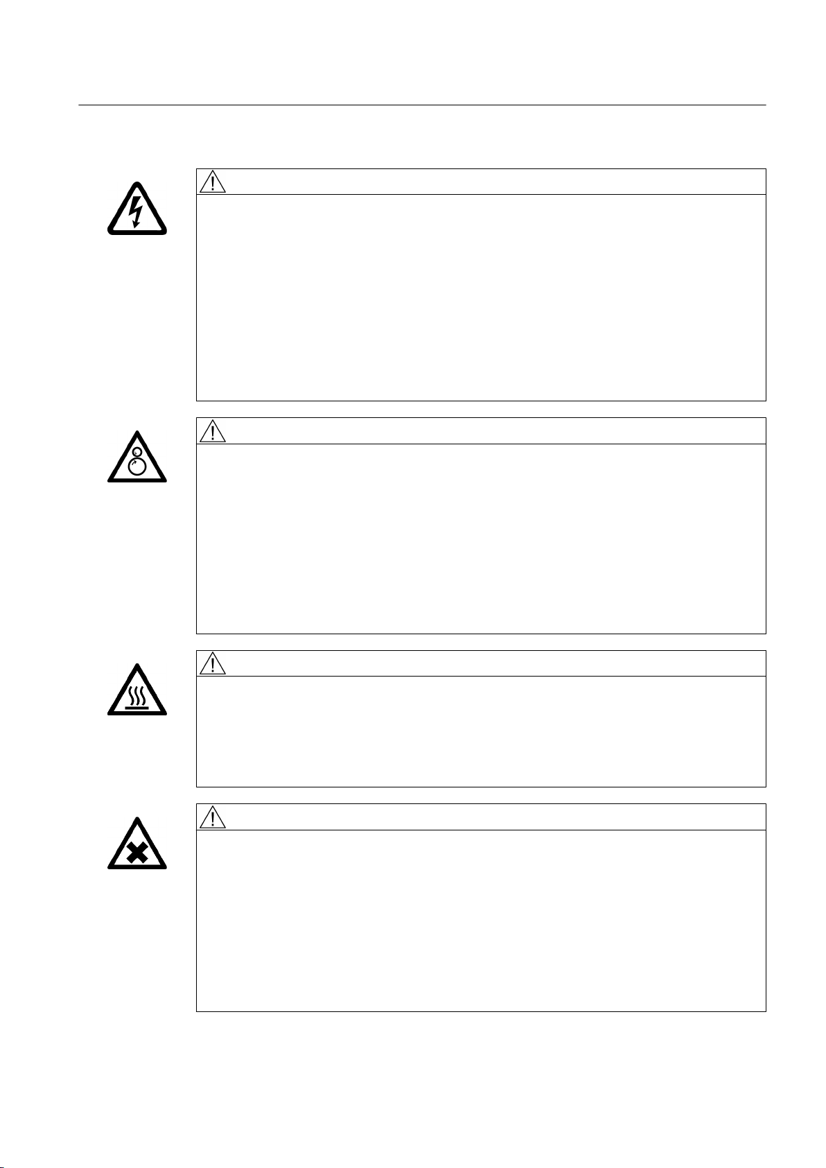
WARNING
Live parts
Electric machines contain live parts.
Fatal or severe injuries and substantial material damage can occur if the covers are removed
or if the machine is not handled, operated, or maintained properly.
● Always observe the “five safety rules" (Page 16) when carrying out any work on the
machine.
● Only remove the covers using the methods described by these operating instructions.
● Operate the machine properly.
● Regularly and professionally maintain the machine according to the instructions provided
in Chapter "Maintenance".
WARNING
Rotating parts
Electric machines contain dangerous rotating parts.
Fatal or severe injuries and substantial material damage can occur if the covers are removed
or if the machine is not handled, operated, or maintained properly.
● Only remove the covers using the methods described by these operating instructions.
● Operate the machine properly.
● Regularly and correctly maintain the machine.
● Secure free shaft extensions and other rotating part such as couplings and pulley belts
so that they cannot be touched.
WARNING
Hot surfaces
Electric machines have hot surfaces. Touching hot surfaces can result in severe burns.
● Allow the machine to cool before starting work on the machine.
● Only remove the covers using the methods described by these operating instructions.
● Operate the machine properly.
CAUTION
Hazardous substances
Chemical substances required for the setup, operation and maintenance of machines can
present a health risk.
Poisoning, skin damage, cauterization of the respiratory tract, and other health damage may
result.
● Read the information in these operating instructions and the product information supplied
by the manufacturer.
● Observe the relevant safety regulations and wear the personal protective equipment
specified.
SIMOTICS FD 1MH1
Operating Instructions 08/2017 17
Page 18
Safety information
2.5 For use in hazardous Zone 2 or Zone 22
CAUTION
Flammable substances
Chemical substances required for the setup, operation and maintenance of machines may
be flammable.
Burns and other damage to health and material may result.
● Read the information in these operating instructions and the product information supplied
by the manufacturer.
● Observe the relevant safety regulations and wear the personal protective equipment
specified.
WARNING
Noise emissions
During operation, the machine's noise emission levels can exceed those permitted at the
workplace, which can cause hearing damage.
Take steps to reduce noise, such as introducing covers and protective insulation or adopting
hearing protection measures, so that the machine can be operated safely within your system.
2.5 For use in hazardous Zone 2 or Zone 22
Electrical systems in hazardous areas must be assembled, installed, and operated by the
applicable responsible persons in accordance with the applicable rules and regulations.
Note
The basic requirements relating to electrical systems and their operation in hazardous areas
are described, for instance, in EU Directive 1999/92/EC as well as in IEC / EN 60079-14.
Ignition hazards
The operating company – together with the responsible authorities – must fully evaluate the
operational risks, the local operating conditions and the monitoring methods that are required.
It is essential that the operating company complies with the necessary measures. Regarding
this topic, the machine manufacturer cannot provide any generally applicable
recommendations. Please observe the information in these operating instructions.
Note
The basic requirements relating to the assessment of ignition hazards arising from electrical
equipment and their operation in hazardous zones are specified, for instance, in directives
2014/34/EU (" Explosion protection directive") and 1999/92/EC - as well as in the
IEC / EN 60079 series of standards.
SIMOTICS FD 1MH1
18 Operating Instructions 08/2017
Page 19
If a third-party certification is available for the machine, then carefully comply with the technical
6LW]SODW]
6WHKSODW]
6WHK6LW]SODW]
EE
D
F
D
IIIII
D
FF
H
GG
H
G
data defined in it and any special conditions.
The certificate must be available before commissioning.
2.6 Electrostatic sensitive devices
ESD protective measures
NOTICE
Electrostatic discharge
Electronic modules contain components that can be destroyed by electrostatic discharge.
These components can be damaged or destroyed if they are not handled correctly. To protect
equipment against damage, follow the instructions given below.
● Only touch electronic modules if you absolutely have to work on them.
● The body of the person concerned must have been electrostatically discharged and
grounded immediately before any electronic modules are touched.
● Electronic modules should not be brought into contact with electrically insulating materials,
such as:
– Plastic film
– Plastic parts
– Insulating table supports
– Clothing made of synthetic fibers
● Always place electrostatic sensitive devices on conductive bases.
● Always pack, store and transport electronic modules or components in conductive
packaging, such as:
– Metallized plastic or metal containers
– Conductive foam material
– Domestic aluminum foil
Safety information
2.6 Electrostatic sensitive devices
The necessary ESD protective measures for electrostatic sensitive devices are illustrated once
again in the following drawings:
a = conductive floor surfaceb = ESD table c = ESD shoes
d = ESD overall e = ESD wristband f = cabinet ground connection
SIMOTICS FD 1MH1
Operating Instructions 08/2017 19
Page 20
Safety information
2.7 Processes that generate high levels of electrostatic charge
WARNING
Risk of explosion due to electrostatic discharge
Electrostatic discharge poses a potential ignition source. Dangerous electrostatic charges
can occur, for example as a result of mechanical friction, flowing air that contains particles or persons that are not appropriately grounded, e.g. when carrying out maintenance or
cleaning work.
In an explosive atmosphere, there is a risk of an explosion. This can result in death, serious
injury or material damage.
● Avoid carrying out work specified above on non-metallic parts, e.g. foam rubber for noise
dampeners/attenuators.
● Please comply with ESD protective measures.
2.7 Processes that generate high levels of electrostatic charge
Processes that generate high levels of electrostatic charge, which are far higher than those
generated through manual rubbing, include the following:
● Operation of high-voltage electrodes and ionizers
● Presence of high-speed particles on surfaces, e.g. sprayed charges (electron and ion flows)
in electrostatic coating processes
● Pneumatically conveyed dusts and bulk goods
● Flowing or hydraulically conveyed liquids and drops
● Belts, brushes and foils etc. moved by machines
WARNING
Risk of explosion as a result of processes with high levels of electrostatic charging
Processes with high levels of electrostatic charging can result in propagating brush discharge/
brushing discharge and explosion
This can result in death, serious injury or material damage.
● Avoid all of these processes in areas where there is risk of gas and dust explosions at
non-metallic exposed components, e.g. paint finishes. These discharge types are not
addressed in current standards.
● The non-metallic exposed components, e.g. paint finishes are subject to an electrostatic
suitability test in the factory. When supplied, the motor has its original paint finish.
Use the tested, original paint when repainting or touching up. It is possible to use a paint
that has not been tested by Siemens, which is however suitable from an electrostatic
perspective. The operating company is responsible for carrying out an electrostatic test
of the complete system.
SIMOTICS FD 1MH1
20 Operating Instructions 08/2017
Page 21
Safety information
2.8 Interference immunity
2.8 Interference immunity
By selecting suitable signal cables and evaluation units, companies operating complete plants
and systems must ensure that the interference immunity of the machine is not diminished.
2.9 Influence on the line power supply through a strongly irregular torque
A strongly irregular torque, for example with the drive of a reciprocating motor, forces a nonsinusoidal motor current. The emerging harmonics can have an impermissible influence on
the line power supply via the connection lines.
2.10 Interference voltages when operating the converter
WARNING
Interference voltages when operating the converter
When a converter is in operation, the emitted interference varies in strength depending on
the converter (manufacturer, type, interference suppression measures undertaken). On
machines with integrated sensors (e.g. PTC thermistors), interference voltages caused by
the converter may occur on the sensor lead. This can cause faults which can result in eventual
or immediate death, serious injury or material damage.
● Comply with the EMC information provided by the manufacturer of the converter. This is
how you prevent the limit values stipulated by IEC/EN 61000-6-3 for the drive system
(consisting of the machine and converter) from being exceeded.
● You must put appropriate EMC measures in place.
2.11 Electromagnetic fields when operating electrical power engineering installations
WARNING
Interference to electronic devices caused by electrical power equipment
Electrical power equipment generate electric fields during operation. Potentially lethal
malfunctions can occur in medical implants, e.g. pacemakers, in the vicinity of electrical power
equipment. Data may be lost on magnetic or electronic data carriers.
● It is forbidden for people with pacemakers to enter the vicinity of the machine.
● Protect the personnel working in the plant by taking appropriate measures, such as
erecting identifying markings, safety barriers and warning signs and giving safety talks.
● Observe the nationally applicable health and safety regulations.
● Do not carry any magnetic or electronic data media.
SIMOTICS FD 1MH1
Operating Instructions 08/2017 21
Page 22

Safety information
2.11 Electromagnetic fields when operating electrical power engineering installations
SIMOTICS FD 1MH1
22 Operating Instructions 08/2017
Page 23
Description
Applications
This electrical machine has been designed for a wide range of drive and energy conversion
applications. The machines are characterized by extreme ruggedness, long service life, and
overall reliability. They are also highly versatile, allowing them to be tailored to specific
functions.
Details of the supplied machine and permissible operating conditions can be found in this
documentation.
The machine was designed in accordance with the ordering party's specification and may only
be used for the contractually agreed purpose. The permissible operating conditions are
specified on the rating plate. The technical data are described in the catalog.
Ex nA or Ex ec type of protection
This machine has Ex nA or Ex ec type of protection according to IEC / EN 60079-15 or -7. It
can therefore be operated in hazardous areas of Zone 2 according to IEC / EN 60079‑10-1.
3
Machine design
WARNING
Explosion hazard
This machine is not designed for use in areas at risk of dust explosion or in areas where an
explosion hazard exists due to hybrid mixtures. An explosion can occur if the machine is
operated in these areas. This can result in death, serious injury or material damage.
● Never operate this machine in the presence of explosive dust or in areas where an
explosion hazard exists due to hybrid mixtures.
The regulations and standards used as the basis to design and test this machine are stamped
on the rating plate.
The machine design basically complies with the subsequent standards. Please refer to the EU
Declaration of Conformity for the versions of the harmonized standards referenced.
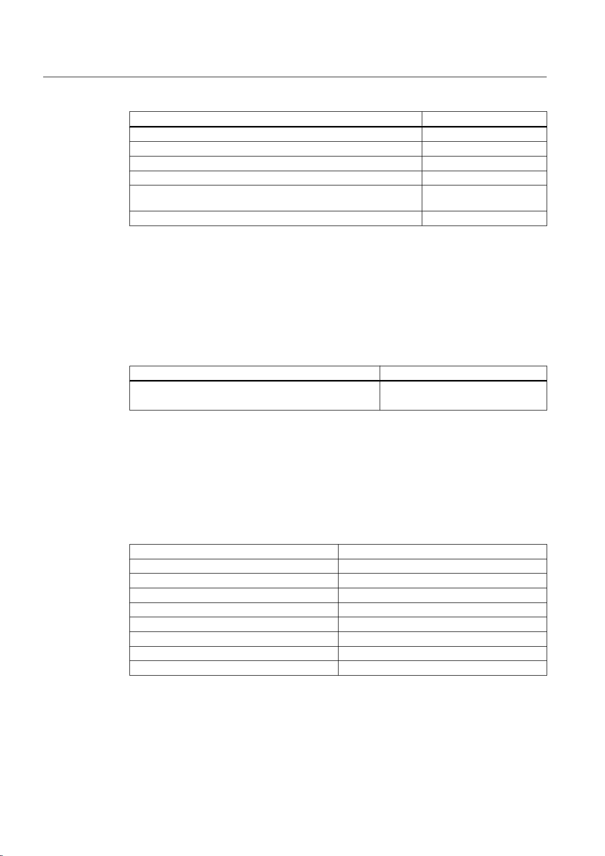
Table 3-1 Machine design
Feature Standard
Rating and performance IEC/EN 60034‑1
Degree of protection IEC/EN 60034‑5
Cooling IEC/EN 60034‑6
Type of construction IEC/EN 60034‑7
SIMOTICS FD 1MH1
Operating Instructions 08/2017 23
Page 24
Description
3.1 Comparison of IEC and GOST standards
Feature Standard
Terminal markings and direction of rotation IEC/EN 60034‑8
Noise emission IEC/EN 60034‑9
Starting characteristics of rotating electrical machines * IEC/EN 60034‑12
Vibration severity grades IEC/EN 60034‑14
Efficiency classification of three-phase squirrel-cage induction motors **IEC/EN 60034-30-1
Vibration limits DIN ISO 10816-3
* For machines in line operation only
** Exception: Pole-changing motors
See also
Quality documents (Page 181)
The following standards additionally apply for explosion-proof machines:
Table 3-2 Machine design with type of protection Ex nA or Ex ec
Feature Standard
Type of protection Ex nA or Ex ec
①
Optional (depending on order)
①
3.1 Comparison of IEC and GOST standards
Comparison of IEC and GOST standards
The IEC/EN standards correspond to the following GOST standards.
IEC/EN GOST
IEC/EN 60034-1 GOST R IEC 60034-1
IEC/EN 60034-5 GOST R IEC 60034-5
IEC/EN 60034-6 GOST R IEC 60034-6
IEC/EN 60034-7 GOST R IEC 60034-7
IEC/EN 60034-8 GOST R IEC 60034-8
IEC/EN 60034-9 GOST R IEC 60034-9
IEC/EN 60034-12 GOST R IEC 60034-12
IEC/EN 60034-14 GOST R IEC 60034-14
IEC/EN 60079‑0
IEC / EN 60079-15 or -7
This machine has been designed and built in accordance with Directive 2014/34/EU and
Customs Union Technical Regulation "On safety of equipment intended for use in explosive
atmospheres" (TR CU 012/2011) and is intended for use in industrial plants with potentially
explosive atmospheres.
SIMOTICS FD 1MH1
24 Operating Instructions 08/2017
Page 25

3.1 Comparison of IEC and GOST standards
The IEC/EN standards correspond to the following GOST standards.
IEC/EN GOST
IEC/EN 60079-0 GOST R IEC 60079-0
IEC/EN 60079-2 GOST IEC 60079-2
IEC/EN 60079-7 GOST R IEC 60079-7
IEC/EN 60079-10 GOST IEC 60079-10
IEC/EN 60079-14 GOST IEC 60079-14
IEC/EN 60079-15 GOST R IEC 60079-15
Ex marking for type of protection Ex nA IIC T3 Gc or Ex ec IIC T3 Gc
Description
II 3 G Ex nA
ec
IIC T3 Gc
① ② ③ ④ ⑤ ⑥ ⑦ ⑧ ⑨ ⑩
AA87
2 Ex nA IIC T3 Gc X
① ⑪ ② ⑫ ⑥ ⑦ ⑧ ⑨ ⑩ ⑬
① CE- or EAC marking
② Code for prevention of explosions
③ Equipment group: II not for mining, but other hazardous zones
④ Device category: 3 for infrequent, short-term danger
⑤ Atmosphere: G for gas
⑥ Explosion protection: International
⑦ "nA" or "ec" type of protection
⑧ Explosion group: IIC for acetylene
⑨ Temperature Class: T3 for maximum surface temperature 200 °C
⑩ Device protection level: Gc for an extended level of protection in hazardous zones with
explosive gas mixtures
⑪ Identification number or name of nominated testing agency
⑫ Zone 2
⑬ "X" special conditions
Ex marking for type of protection Ex nA IIB T3 Gc or Ex ec IIB T3 Gc
II 3 G Ex nA
ec
IIB T3 Gc
① ② ③ ④ ⑤ ⑥ ⑦ ⑧ ⑨ ⑩
SIMOTICS FD 1MH1
Operating Instructions 08/2017 25
Page 26

Description
3.1 Comparison of IEC and GOST standards
AA87
① ⑪ ② ⑫ ⑥ ⑦ ⑧ ⑨ ⑩ ⑬
① CE- or EAC marking
② Code for prevention of explosions
③ Equipment group: II not for mining, but other hazardous zones
④ Device category: 3 for infrequent, short-term danger
⑤ Atmosphere: G for gas
⑥ Explosion protection: International
⑦ "nA" or "ec" type of protection
⑧ Explosion group: IIB for ethylene
⑨ Temperature Class: T3 for maximum surface temperature 200 °C
⑩ Device protection level: Gc for an extended level of protection in hazardous zones with
explosive gas mixtures
⑪ Identification number or name of nominated testing agency
⑫ Zone 2
⑬ "X" special conditions
2 Ex nA IIB T3 Gc X
Rating plate
The rating plate shows the identification data and the most important technical data. The data
on the rating plate and the contractual agreements define the limits of proper usage.
SIMOTICS FD 1MH1
26 Operating Instructions 08/2017
Page 27
'(:
RR
RR
SIEMENS
Description
3.1 Comparison of IEC and GOST standards
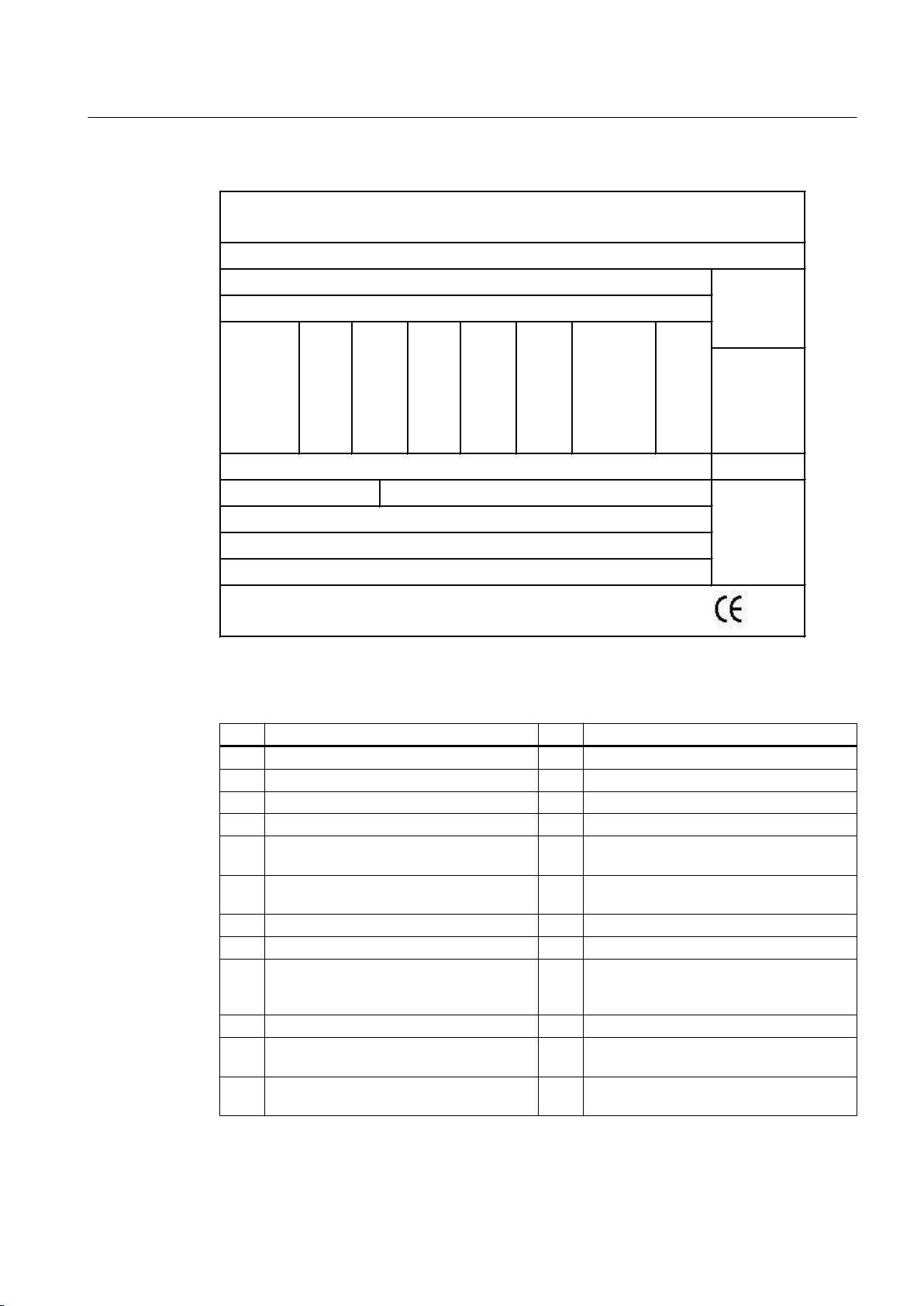
Figure 3-1 Schematic of the rating plate
Table 3-3 Data on the rating plate
Item Description Item Description
(1) Type of motor (15) Rated power [kW or HP]
(2) Order number (16) Rated efficiency factor
(3) Identifier of the motor series (17) Rated speed [rpm]
(4) Serial number (18) Rated frequency [Hz]
(5) Weight (19) Efficiency class (IE code) or efficiency ac‐
(6) Degree of protection (20) Efficiency according to IEC/EN 60034-2-1
(7) Type of construction (21) Motor design (converter or mains motor)
(8) Permissible ambient temperature range (22) Line voltage/frequency
(9) Thermal class of the insulation system (23) Optional additional data (e.g. service fac‐
(10) Thermal class of the utilization (24) Country of manufacture and location
(11) Maximum speed [rpm] (25) Certification mark for UL/CSA + file number
(12) Standards (26) Certificate number(s) for Ex motors for
cording to IEEE112B or empty
or current at service factor power
tor, design and code letter, amount of cool‐
ing water and intake temperature, etc.)
(optional)
Zone 2 (optional)
SIMOTICS FD 1MH1
Operating Instructions 08/2017 27
Page 28

Description
3.1 Comparison of IEC and GOST standards
Item Description Item Description
(13) Rated voltage [V] and connections (27) Direction of rotation
(14) Rated current [A] (28) Data matrix code (order number and serial
Relevant directives
The following directives are relevant for the SIMOTICS motor series.
European low-voltage directive
The SIMOTICS motor series complies with the requirements of the low-voltage directive
2014/35/EU.
European machinery directive
The SIMOTICS motor series does not fall within the area of validity of the machinery directive.
However, the use of the products in a typical machine application has been fully assessed for
compliance with the main regulations in this directive concerning health and safety.
European EMC Directive
The SIMOTICS motor series does not fall within the area of validity of the EMC directive. The
products are not considered as devices in the sense of the directive.
number)
Eurasian conformity
The SIMOTICS motor series complies with the requirements of the Russia/Belarus/
Kazakhstan customs union (EAC).
China Compulsory Certification
The SIMOTICS motor series does not fall in the area of validity of the China Compulsory
Certification (CCC).
Underwriters Laboratories
The SIMOTICS motor series generally complies with UL and cUL requirements as component
of motor applications - and is correspondingly listed. Specifically developed motors and
functions are the exceptions in this case. Here, it is important that you carefully observe the
contents of the quotation and that there is a cUL mark on the rating plate (nameplate)!
Quality management system
Siemens AG employs a quality management system that meets the requirements of ISO 9001
and ISO 14001.
Certificates that can be downloaded
You can download certificates for the SIMOTICS motor series at the following link:
Certificates (https://support.industry.siemens.com/cs/ww/en/ps/13358/cert)
SIMOTICS FD 1MH1
28 Operating Instructions 08/2017
Page 29

Rotors
Drive
Line operation
Description
3.1 Comparison of IEC and GOST standards
The rotor assembly is pressed onto the shaft together with the cage winding. The drive end of
the shaft usually has a cylindrical shaft end. Dependent on the design, a second shaft end
may be located at the non-drive end.
The motor speed is controlled using a converter. It has been optimized for operation with
SINAMICS low-voltage converters.
Other converters must comply with certain requirements: You can find more information in the
catalog or in the engineering documentation.
The motor is supplied from the line system.
NOTICE
Destruction of the machine when operated directly from the line supply
The machine will be destroyed if it is directly connected to the line supply. Only operate the
machine using a converter.
NOTICE
Machine damage for operation on the converter
If you connect the machine to a converter, the machine can be damaged. Operate the
machine only on the electrical supply system.
Cooling
The cooling system is designed as a closed, internal cooling circuit. The heat lost from the
machine is dissipated partially via heat conduction and partially via the cooling air at the cooling
water flowing through the cooling pipes. A shaft-mounted fan ensures circulation of the cooling
air.
Degree of protection
The machine is available with degree of protection IP55.
SIMOTICS FD 1MH1
Operating Instructions 08/2017 29
Page 30

Description
3.1 Comparison of IEC and GOST standards
Rolling-contact bearings
The machines are equipped with different types of rolling-contact bearings depending on the
version and the operating conditions described in the order. The different types are listed on
the lubricant plate of the machine. In converter operation an insulated bearing is usually
installed on the non-drive end. The following rolling-contact bearing variants are available:
Table 3-4 Rolling-contact bearing variants
Version Rolling-contact bearing
Horizontal type of construction,
coupling output
Horizontal type of construction,
for increased transverse forces
e.g. in the case of belt coupling
Vertical type of construction,
shaft height 315, coupling output
Vertical type of construction,
shaft height 355 ... 450
● Drive end: Deep-groove ball bearing as a fixed bearing
● Non-drive end: Deep-groove ball bearing as a floating bearing
with axial compression springs
● Drive end: Cylindrical-roller bearing as a floating bearing
● Non-drive end: Deep-groove ball bearing as a fixed bearing
● Drive end: Deep-groove ball bearing as a fixed bearing
● Non-drive end: Deep-groove ball bearing as a floating bearing
with axial compression springs
● Drive end: Pairing of angular-contact ball bearing / deep-groove
ball bearing as a fixed bearing
● Non-drive end: Deep-groove ball bearing as a floating bearing
with axial compression springs
Automatic regreasing system (option)
The roller bearings are optionally equipped with an automatic regreasing system. The roller
bearings are supplied with new grease portions by the regreasing system in parameterized
time intervals.
Rolling-contact bearing design for "Increased degree of protection" (option)
Improved sealing of the bearing units to prevent dust and water from getting in can be achieved
by positioning a grease chamber ahead of the actual bearing unit. Although the same grease
is used in both cases for reasons of convenience, a distinction is made here between
"lubricating grease" and "sealing grease" because of their different functions.
Layout
The spent lubricating grease collects in the space between the bearing housing and the outer
bearing cap. The latter also forms the sealing grease chamber with the labyrinth sealing ring
(optional). The second lubricating nipple containing the grease duct for pressing in the sealing
grease is also located in the outer bearing cap. The chamber is sealed off from the space
where the lubricating grease collects by a V-ring or a V-ring and felt ring combination which
prevents the sealing grease in the chamber from penetrating into the lubricating grease
collecting space. During operation, the sealing grease in the chamber slowly runs out via the
labyrinth and seals it, additionally removing dust from inside and around the outside of the
labyrinth ring.
SIMOTICS FD 1MH1
30 Operating Instructions 08/2017
Page 31

Terminal box
Description
3.1 Comparison of IEC and GOST standards
Depending on the machine design, the following terminal boxes are generally used for
connecting the cables:
Terminal box Comment Application
GT640 Only for machines on the
power supply
1XB1621
1XB1631 2 × 1XB1631
1XB7730 Not for IEC explosion-proof versions
1XB7731 Not for IEC explosion-proof versions
1XB7740 2 × 1XB7740 Not for IEC explosion-proof versions
1XB7750
Not for explosion-proof versions
Depending on the terminal box and version, it is possible to rotate the terminal box through
±90° in accordance with the connection direction. The implementation on the other motor side
is possible only with the support of the Service Center. If you wish to retrofit using a different
terminal box at a later date, please contact the Service Center (Page 177).
See also
Rotating the terminal box (Page 85)
Terminal box (Page 80)
Note
You can find more information in Chapter 2 of catalog D81.8.
Supplementary devices
Depending on the order, various supplementary devices can be installed or mounted. These
include sensors for bearing temperature monitoring or winding monitoring, for example.
Anti-condensation heating (option)
The machine is fitted with anti-condensation heating. The connection data is listed on an
additional plate on the machine.
SIMOTICS FD 1MH1
Operating Instructions 08/2017 31
Page 32

Description
3.1 Comparison of IEC and GOST standards
SIMOTICS FD 1MH1
32 Operating Instructions 08/2017
Page 33

Preparations for use
Good planning and preparation of machine applications are essential in terms of keeping
installation simple and avoiding errors, ensuring safe operation, and allowing access to the
machine for servicing and corrective maintenance.
This chapter outlines what you need to consider when configuring your plant in relation to this
machine and the preparations you need to make before the machine is delivered.
4.1 Safety-related aspects to consider when configuring the plant
A number of residual risks are associated with the machine. These are described in the chapter
titled "Safety information" (Page 15) and in related sections.
Take appropriate safety precautions (covers, barriers, markings, etc.) to ensure the machine
is operated safely within your plant.
4.2 Observing the operating mode
Observe the machine's operating mode. Use a suitable control system to prevent overspeeds,
thus protecting the machine from damage.
4
4.3 Ensuring cooling
Ensure that the machine and/or any mounted external fan unit is sufficiently cooled by the
cooling air flow at the installation site:
● The cooling air can flow in and out freely. The full air flow provided by the fan is only achieved
if air can freely enter the impeller. Ensure that the required distance in accordance with the
dimensioned drawing is maintained.
● Hot discharged air must not be drawn in again.
● On the vertical design with air intake from above, the air inlets must be protected against
the ingress of foreign bodies and water.
4.4 Configuration of the cooling circuit and coolant supply
4.4.1 Material selection for the cooling circuit
For optimum durability of the cooling system, use a closed or half open cooling circuit in
stainless steel or acrylic butadiene styrene (ABS).
SIMOTICS FD 1MH1
Operating Instructions 08/2017 33
Page 34

Preparations for use
4.4 Configuration of the cooling circuit and coolant supply
Use either stainless steel or steel (S235JR) for the cooling circuit pipes and fittings.
4.4.2 Pressures and differential pressures in the cooling circuit
The maximum permissible overpressure in the heat sink and thus in the cooling circuit must
not exceed 6 bar.
● If you are using a pump, which reaches more than this maximum pressure, then on the
plant or system side ensure that the maximum pressure is not exceeded.
● The lowest possible differential pressure between the coolant in the supply and return lines
should be selected to allow use of pumps with a flat characteristic. The maximum differential
pressure for a heat sink varies from shaft height to shaft height. Higher pressure differences
significantly increase the risk of cavitation and abrasion.
Machine type Flow rate ± 10 %
[l/min]
1LH….-3A…-….
1MH….-3A…-….
1LH….-3B…-….
1MH….-3B…-….
1LH….-4A…-….
1MH….-4A…-….
1LH….-4B.1.-….
1MH….-4B.1.-….
1LH….-4B.3.-….
1MH….-4B.3.-….
1LH….-4B.5.-….
1MH….-4B.5.-….
1LH….-4B.7.-….
1MH….-4B.7.-….
40 1.0
40 1.2
60 1.1
60 1.2
60 1.2
80 1.2
80 1.2
Pressure drop for fresh water
[bar]
● The pressure drop is dependent on the machine type. The machine type is stamped on the
rating plate.
● If there is a risk of frost, use cooling water with antifreeze suitable for this temperature.
The pressure drop increases when antifreeze is added.
See also
Connecting the cooling water supply (Page 77)
SIMOTICS FD 1MH1
34 Operating Instructions 08/2017
Page 35

Preparations for use
4.4 Configuration of the cooling circuit and coolant supply
4.4.3 Components and materials of the cooling circuit
The following table lists a wide variety of materials and components which can occur in a
cooling circuit or which are prohibited.
Table 4-1 Materials and components of a cooling circuit
Material Component Remark
Zinc Pipes, valves and fit‐
tings
Brass Pipes, valves and fit‐
tings
Copper Pipes, valves and fit‐
tings
Steel (e.g. S235JR) Cable Can be used in closed cooling circuits with inhibitors or anti-freeze.
Cast steel, cast iron Pipes, motors Can be used in closed cooling circuits. Use sieves and return flush
High-alloy steel, Group 1
(V2A)
High-alloy steel, Group 2
(V4A)
Installation employing differ‐
ent materials ("mixed instal‐
lation")
PVC Pipes, valves and fit‐
Hoses Reduce the use of hoses for connecting devices to a minimum. Do
Gaskets Pipes, valves and fit‐
Hose connections Transition from pipe to
Pipes, valves and fit‐
tings
Pipes, valves and fit‐
tings
Pipes, valves and fit‐
tings
tings, hoses
tings
hose
Do not use any components manufactured out of zinc.
Can be used in closed cooling circuits with inhibitor.
Can only be used in closed cooling circuits with inhibitor. Locate an
isolating element, e.g. connecting pipe of the devices, between the
heat sink and copper component.
Check for the formation of oxide; to do this, use a sight glass, for
example.
filter; for stainless steel cooling systems, use a Fe separator.
Can be used for drinking or municipal water with a chloride content
< 250 ppm.
Can be used for drinking or municipal water with a chloride content
< 500 ppm.
Do not use a mixed installation.
Do not use any components manufactured out of PVC.
not use any hoses as main connecting line for the complete system.
Recommendation: EPDM hoses with an electrical resistance > 109
Ω, e.g. "Semperflex FKD" supplied from Semperit or "DEMITTEL"
from PE/EPD, supplied from the Telle company.
Use seals manufactured from fluorinated rubber in accordance with
DIN ISO 1629, AFM34, EPDM (recommended).
Fasten the hose connections with bracket clamps in accordance
with EN 14420.
4.4.4 Potential equalization on the cooling circuit components
● Connect an equipotential bonding conductor to all of the components in the cooling system
(motor, converter, piping system, etc.).
● Implement the equipotential bonding using a copper rail or finely stranded copper cable
with the appropriate cable cross-sections. In this way, you suppress electrochemical
processes.
SIMOTICS FD 1MH1
Operating Instructions 08/2017 35
Page 36
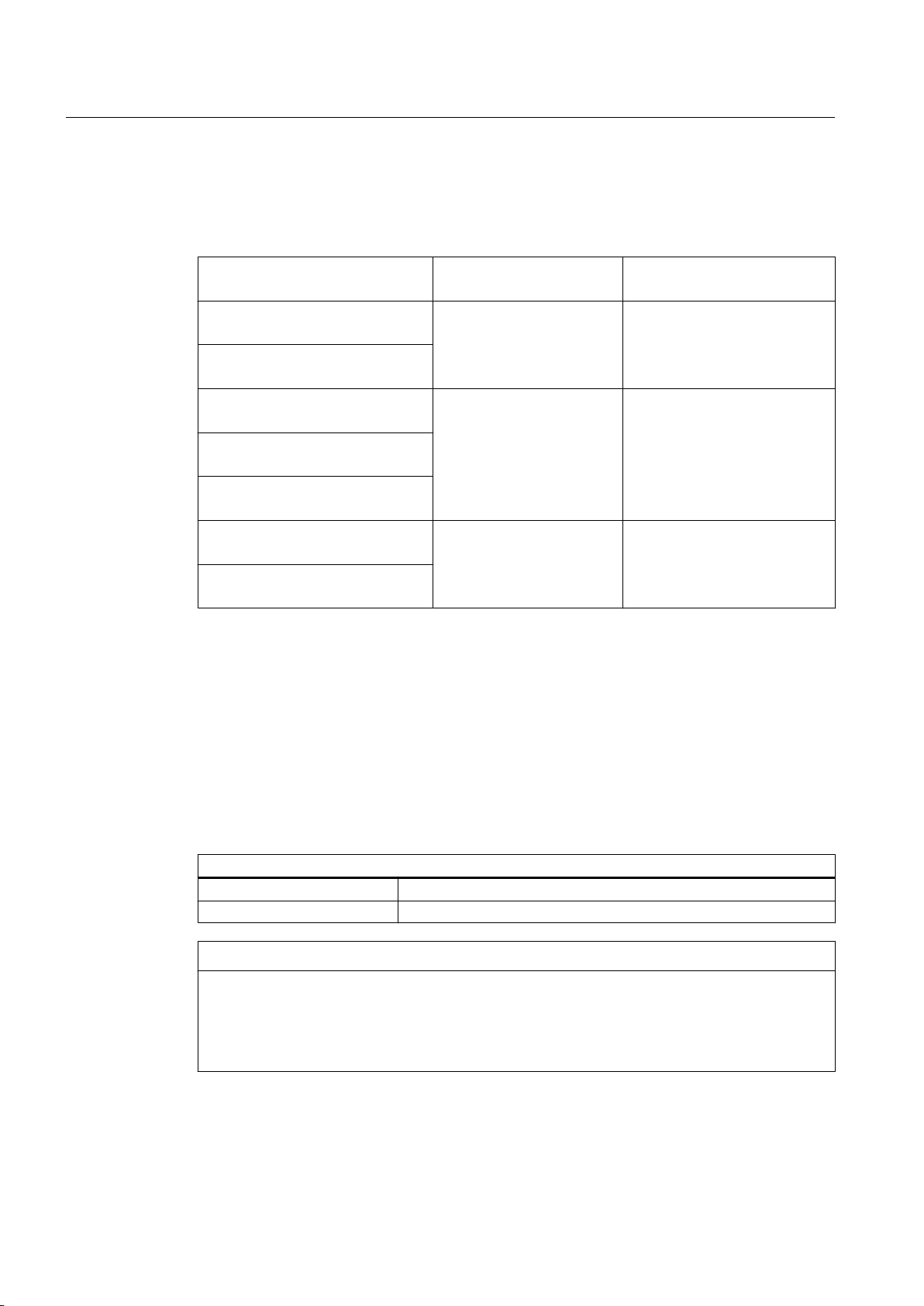
Preparations for use
4.5 Coolant specification
4.4.5 Power loss
When dimensioning the cooling system, take into account the power losses as a function of
the flow rate for the rated data.
Machine type Flow rate ± 10 %
1LH….-3A…-….
1MH….-3A…-….
1LH….-3B…-….
1MH….-3B…-….
1LH….-4A…-….
1MH….-4A…-….
1LH….-4B.1.-….
1MH….-4B.1.-….
1LH….-4B.3.-….
1MH….-4B.3.-….
1LH….-4B.5.-….
1MH….-4B.5.-….
1LH….-4B.7.-….
1MH….-4B.7.-….
Power losses as a function of the flow rate for the rated data.
4.5 Coolant specification
[l/min]
40
60
80
Power loss
[kW]
28
42
56
4.5.1 General coolant requirements
The coolant must fulfill the following requirements over the long term. The coolant is based on
filtered drinking/municipal water of the quality specified below.
De-ionized water
Specific conductivity < 30 μS/cm
Evaporation residue < 20 mg/l
NOTICE
High percentage of chloride in drinking water
According to Directive 98/83/EC, drinking water may contain up to 250 mg/l of chloride. This
value is too high for the heat sinks, which may be destroyed if inhibitors are not added.
Use inhibitors if the drinking water has an excessively high chloride percentage.
To better explain the coolant recommendations in this document, some of the problems that
can be encountered if the recommendations are ignored are listed in the table below.
SIMOTICS FD 1MH1
36 Operating Instructions 08/2017
Page 37

Table 4-2 Substances that can destroy the cooling system
Preparations for use
4.5 Coolant specification
Coolant property or limit value vi‐
olation
Seawater Do not use seawater.
Water compliant with limit values Use inhibitors/antifreeze with the appropriate concentration. Locate
Entry of oxygen Use a closed cooling circuit. Locate a pressure relief valve in the
Chloride Use inhibitors/antifreeze with the appropriate concentration.
Sulfate Dilute the coolant using de-ionized water until the limit value is
Solids (e.g. sand) Flush the cooling circuit, without converter and motor. Use dirt fil‐
Total hardness Use inhibitors/antifreeze with the appropriate concentration.
Conductivity Connect an equipotential bonding conductor to all cooling circuit
Biological contamination Use biocides. Use dirt filtering equipment, e.g. sieves, fine filters.
Oil residue Use inhibitors/antifreeze with the appropriate concentration.
Mechanical contamination Flush the cooling circuit, without converter and motor. Use dirt fil‐
Inadequate equipotential bond‐
ing
Countermeasure
a pressure relief valve in the cooling circuit.
cooling circuit.
Use inhibitors/antifreeze with the appropriate concentration.
reached.
tering equipment, e.g. sieves, fine filters.
components.
Flush the cooling circuit, without converter and motor.
tering equipment, e.g. sieves, fine filters.
Connect an equipotential bonding conductor to all cooling circuit
components.
See also
Inhibitors, anti-freeze, biocides (Page 39)
Cooling water intake temperature
The maximum cooling water intake temperature is 25 °C.
NOTICE
Condensation for an excessively low cooling water intake temperature
If the temperature difference between cooling water and ambient temperature is greater than
5 K, this may result in condensation forming in the machine. This results in material damage.
● Make sure that the condensation can drain away freely.
● Adopt appropriate measures to achieve the required intake temperature of the cooling
water.
● Alternatively, dry the ambient air.
SIMOTICS FD 1MH1
Operating Instructions 08/2017 37
Page 38
Preparations for use
4.5 Coolant specification
NOTICE
Corrosion due to insufficient cooling water quality
The materials used in the cooler are selected to match the cooling water quality for which the
air-water cooler was ordered. The cooler cannot be simply used without taking any other
measures if other water conditions apply. If the cooling water quality is unsuitable, the air-towater heat exchanger may suffer corrosion and fail.
● The chemical composition of the cooling water must comply with the configuration
specifications.
● If the cooling water quality fails to satisfy the quality stated on the order, please contact
the Service Center.
● Please observe the recommended water quality in the operating instructions for the airwater cooler.
NOTICE
Overheating of the machine as a result of additives in the cooling water
Additives for antifreeze or corrosion protection can have a negative impact on the heat
transporting properties. The machine can overheat.
● Only operate the machine with the contractually agreed cooling water quality.
See also
Service and Support (Page 177)
4.5.2 Coolant specification (M85 "stainless steel version" option)
Drinking or municipal water (option M85: Stainless steel version)
pH value 6.5 ... 9.5
Chloride ions Cl
Sulfate ions SO
Nitrate ions NO
Dissolved solids < 340 mg/l
Total hardness < 1.7 mmol/l
Electrical conductivity < 2000 μS/cm
Maximum size of dissolved substances < 0.1 mm
-
2-
4
+
3
< 200 mg/l
< 240 mg/l
< 50 mg/l
SIMOTICS FD 1MH1
38 Operating Instructions 08/2017
Page 39

Preparations for use
4.5 Coolant specification
4.5.3 Inhibitors, anti-freeze, biocides
You can use the following anti-freeze, inhibitors and biocides in the stainless steel cooling
circuit:
Table 4-3 Overview and application of coolant additives
Anti-freeze used Please note the following in particular
Inhibitor without anti-
freeze effect
Anti-freeze protection
Biocide* Yes
Antifreeze + biocide* An Antifrogen N antifreeze concentration of >20 %
Not necessary Inhibitor, 0.2 ... 0.25 % by volume!
● Antifrogen N: 20 % < X ≤ 45 %
A 45 % concentration provides frost protection
down to -15 °C.
● Antifrogen L: 25 % < X ≤ 48 %
A 48 % concentration provides frost protection
down to -15 °C.
● Varidos FSK: 20 % < X ≤ 45 %
A 45 % concentration provides frost protection
down to -15 °C.
● Antifrogen N, minimum quantity 20 %
● Antifrogen L, minimum quantity 30 %
● Varidos FSK, minimum quantity 30 %
provides an adequate biocidal effect.
With Antifrogen L and Varidos FSK, 30 % is required
in order to achieve the same effect.
● With Antifrogen L, for the same
antifreeze protection, a higher
concentration is required then for
Antifrogen N
Cooling circuit with open pressurizer
* Effectiveness regarding the growth of microorganisms
Inhibitor without anti-freeze effect
If you use inhibitors without any antifreeze effect, then it is not permissible that there is any
magnesium carbonate in the cooling/water used.
Only use the NALCO TRAC100 inhibitor from the Nalco company in the ratio 0.2 % up to
0.25 %. Control Kits can be ordered from Nalco to check the inhibitor concentration.
Anti-freeze
All antifreeze agents contain corrosion protection inhibitors, which permanently protect the
cooling system against corrosion. You can use the additives listed above as anti-freeze agent:
NOTICE
Corrosive mixture
Top up with antifreeze to comply with the minimum concentration, otherwise a mixture is
obtained that has a corrosive effect. The cooling system can be damaged.
● Never mix inhibitors and anti-freeze.
SIMOTICS FD 1MH1
Operating Instructions 08/2017 39
Page 40
Preparations for use
4.5 Coolant specification
Biocides
Closed cooling circuits with soft water (°dH > 4) are susceptible to microbes. The risk of
corrosion caused by microbes is virtually non-existent in chlorinated drinking water systems.
No strain of bacteria can survive when the appropriate quantity of anti-freeze is added. The
following microbes can occur:
● Bacteria that cause the formation of slime
● Corrosive bacteria
● Bacteria that cause deposits of iron
The type of bacteria determines the suitability of a biocide. At least one water analysis per
annum (to determine the number of bacterial colonies) is recommended. You can purchase
suitable biocides, for example from Nalco.
Note
Determining the appropriate biocide
The type of bacteria determines the biocide. Antifreeze already has a biocidal effect for the
minimum concentration specified above.
● The manufacturer's recommendations must be followed in regard to the dosage and
compatibility with any inhibitor that might be used.
● Never mix biocides and anti-freeze.
4.5.4 Cooling capacity derating
If you use antifreeze, then observe the cooling capacity derating factor, dependent on the
antifreeze concentration, as listed in the table.
Anti-freeze Concentration Cooling capacity derating factor
Antifrogen N
Varidos FSK
Antifrogen L
Antifrogen N / Varidos FSK ≙ ethylene glycol
Antifrogen L ≙ propylene glycol
Note
Order-specific agreements
Order-specific agreements regarding the cooling water specification can deviate from the
cooling water specification mentioned.
20% 0%
25% 0%
30% 0%
35% 2%
40% 4%
45% 5%
SIMOTICS FD 1MH1
40 Operating Instructions 08/2017
Page 41
Preparations for use
4.6 Thermal motor protection
4.6 Thermal motor protection
The machine is equipped with measuring equipment for direct monitoring of the motor
temperature to protect the machine against overload during operation. Plan a corresponding
circuit for monitoring.
4.7 Thermal motor protection using PTC thermistors (option)
The machine is equipped with PTC thermistors for direct monitoring of the motor temperature
to protect the machine against overheating during operation. Plan a corresponding circuit for
monitoring.
4.8 Interlock circuit for the automatic regreasing system (option)
Relubrication is permitted only for a rotating shaft. Consequently, deploy an interlock circuit
for machines with automatic regreasing system to prevent them from operating at machine
standstill.
4.9 Interlock circuit for anti-condensation heating
If the anti-condensation heating is operated while the machine is running, this can increase
the temperatures inside the machine.
● Install an interlock circuit that switches off the anti-condensation heating once the main
machine is switched on.
● Only switch on the anti-condensation heating after the machine has been switched off.
See also
Switching off the anti-condensation heating (Page 124)
WARNING
Explosion hazard
If the anti-condensation heating is switched on directly after the machine is switched off, the
temperature class or the maximum surface temperature of the machine can be exceeded.
In an explosive atmosphere, there is a risk of an explosion. This can result in death, serious
injury or material damage.
● Only switch on the anti-condensation heating after the motor has been switched off.
Carefully comply with the data on the anti-condensation heating plate.
SIMOTICS FD 1MH1
Operating Instructions 08/2017 41
Page 42
Preparations for use
4.10 Support base for IM B5 construction type
4.10 Support base for IM B5 construction type
● For machines, type of construction IM B5, provide an additional support foot at the NDE.
The support foot is not included in the scope of supply.
● Use an appropriately sized support foot with the appropriate rigidity. The support foot must
be able to support the total weight of the machine.
The weight of the machine is stated on the rating plate, data on geometry is shown in the
dimension drawing.
● There is a threaded hole M36 at the bottom of the machine where you can attach the support
foot.
WARNING
Missing support at the NDE
If the machine has no support at the NDE, the flange cannot hold the weight of the machine.
The machine or machine parts may loosen.
This can result in death, serious injury or material damage.
● Use an appropriately sized support base.
4.11 Noise emissions
WARNING
Noise emissions
During operation, the machine's noise emission levels can exceed those permitted at the
workplace, which can cause hearing damage.
Take steps to reduce noise, such as introducing covers and protective insulation or adopting
hearing protection measures, so that the machine can be operated safely within your system.
4.12 Rotational speed limit values
WARNING
Excessively high speeds
Excessive rotational speed can lead to serious damage to the machine. This can result in
death, serious injury, or material damage.
● Avoid operation above the permissible speed by using the appropriate control function.
● Observe the speeds stamped on the rating plate.
SIMOTICS FD 1MH1
42 Operating Instructions 08/2017
Page 43

Preparations for use
4.13 Complying with speed-torque curve
4.13 Complying with speed-torque curve
WARNING
Exceeding the temperature class
If the speed-torque curve is not followed, the temperature class may be exceeded. An
explosion can occur. This can result in death, serious injury or material damage.
● Comply with the speed-torque curve.
● Observe the data on the extra rating plate on the motor.
4.14 Voltage and frequency fluctuations during line operation
If nothing else is stamped on the rating plate, the permissible voltage fluctuation is ±5 % and
the permissible frequency fluctuation is ±2 %, corresponding to range A in IEC/EN 60034-1.
Permissible fluctuations that go beyond these values are stamped on the rating plate.
Under operating conditions a machine may sometimes have to be operated outside the limits
of range A.
● Limit exceptions of this sort with regard to the values that arise, how often, and for how long
they occur.
● Where possible and within a reasonable time take corrective actions such as reducing the
power. Such actions can avoid thermal ageing leading to a reduction in the service life of
the machine.
NOTICE
Overheating of the winding
Exceeding the permissible tolerances for voltage and frequency can lead to an impermissibly
high temperature rise in the windings. This can result in long-term damage to the machine.
4.15 Phase synchronization during supply system switching
NOTICE
Supply system switching
Damage to the machine may be caused when switching to another supply system with
different phasing.
● The phasing must be synchronized during switching. Use appropriate means to
synchronize the phasing.
SIMOTICS FD 1MH1
Operating Instructions 08/2017 43
Page 44
Preparations for use
4.16 System-inherent frequencies
4.16 System-inherent frequencies
NOTICE
System resonances
Excessive vibrations and system resonances can damage the machine set.
● Configure and match the system consisting of the foundation and machine set in such a
way that no system resonances can arise and result in the permissible vibration levels
being exceeded.
● The vibration limit values according to DIN ISO 10816-3 must not be exceeded.
4.17 Torsional load of the drive train
In the event of faults in the electrical connection during operation, excessive air gap torques
can lead to additional mechanical torsional load on the line shaft.
Note
The system planner is responsible for the entire drive train.
WARNING
Torsional loadings of the shaft assembly
If the configuration does not correctly recognize the mechanical torsional loadings of the shaft
assembly, this can lead to serious damage to the machine. This can result in death, serious
injury or material damage.
When planning the system, consider the configuration data.
Note
You can find more information in Chapter 2 of catalog D81.8.
4.18 Transport and storage
Observe the following when carrying out any work on the machine:
● Comply with the general safety instructions
● Comply with the applicable national and sector-specific regulations at the place of
installation
● When using the machine within the European Union, comply with the specifications laid
down in EN 50110‑1 regarding safe operation of electrical equipment.
SIMOTICS FD 1MH1
44 Operating Instructions 08/2017
Page 45

See also
Safety information (Page 15)
4.18.1 Checking the delivery
The components are assembled on an individual basis. When you take receipt of the delivery,
please check immediately whether the scope of the delivery matches up with the
accompanying documents. No claims relating to defects/items missing from the delivery will
be accepted if they are submitted at a later date.
● Report any apparent transport damage to the delivery agent immediately.
● Immediately report any apparent defects/missing components to your contact partner.
These Operating Instructions are part of the scope of delivery; keep them in a location where
they can be easily accessed.
4.18.2 Lifting and transportation
Preparations for use
4.18 Transport and storage
To safely lift and transport the machine, the following requirements must be met:
● Personnel operating cranes and fork-lift trucks must be appropriately qualified.
● If the machine is packed, depending on the weight, size and on-site conditions, lift crates
and transport frames using a fork-lift truck or a crane with slings. Use a crane or fork-lift
truck suitable for the load.
● When lifting the machine, use only approved and undamaged sling guides and spreaders
of sufficient rated capacity. Check the lifting equipment prior to its use. The weight of the
machine is shown on the rating plate.
● When lifting the machine, refer to the information on the lifting plate.
– Comply with the specified spreading angles.
– Do not exceed the maximum lifting acceleration and lifting speed specified on the lifting
plate. Lift the machine without jerking it.
Acceleration a ≤ 0.4 g (≈ 4 m/s2 )
Velocity v ≤ 20 m/min
WARNING
Transport for a different type of construction
If you do not transport or lift the machine in a position appropriate for its construction, the
machine can tip, slip into the lifting equipment or fall down. This can result in death, serious
injury or material damage.
● Use only the load carrying device on the stator frame for lifting.
● Use the load carrying device appropriate for the machine position.
● Only use suitable rope guiding or spreading devices.
SIMOTICS FD 1MH1
Operating Instructions 08/2017 45
Page 46

Preparations for use
4.18 Transport and storage
WARNING
Center of gravity not centered
If the center of gravity of a load is not located centrally between the attachment points, the
machine can tip over or slip out of the lifting equipment and fall when it is being transported
or lifted. This can result in death, serious injury or material damage.
● Comply with the handling instructions on the machine when transporting it.
● Be aware of the possibility of different loads on the sling ropes or lifting straps and the
carrying capacity of the lifting equipment.
● Always take account of the center of gravity when transporting or lifting the machine. If
the center of gravity is not located centrally between the attachment points, then position
the hoisting hook above the center of gravity.
4.18.3 Securing the rotor
Depending on the version, the machine is fitted with a rotor shipping brace. This protects the
bearings against damage due to shock and vibration during transport or storage.
NOTICE
Vibration and shock during transport
Not using the rotor shipping brace can cause damage to the machine if it is jolted during
transport. Material damage can result.
● If the machine is fitted with a rotor shipping brace, this should always be used when
transporting the machine. The rotor shipping brace must be attached during the transport.
● Only remove it before pulling on the output element.
● For machines with a vertical type of construction:
– Do not remove the rotor shipping brace until the machine is in a vertical position.
– If a machine has to be transported in a horizontal position, the rotor must be fixed in
position before the machine is turned onto its side. Vertical machines can be supplied
in the horizontal position from the manufacturing plant.
SIMOTICS FD 1MH1
46 Operating Instructions 08/2017
Page 47
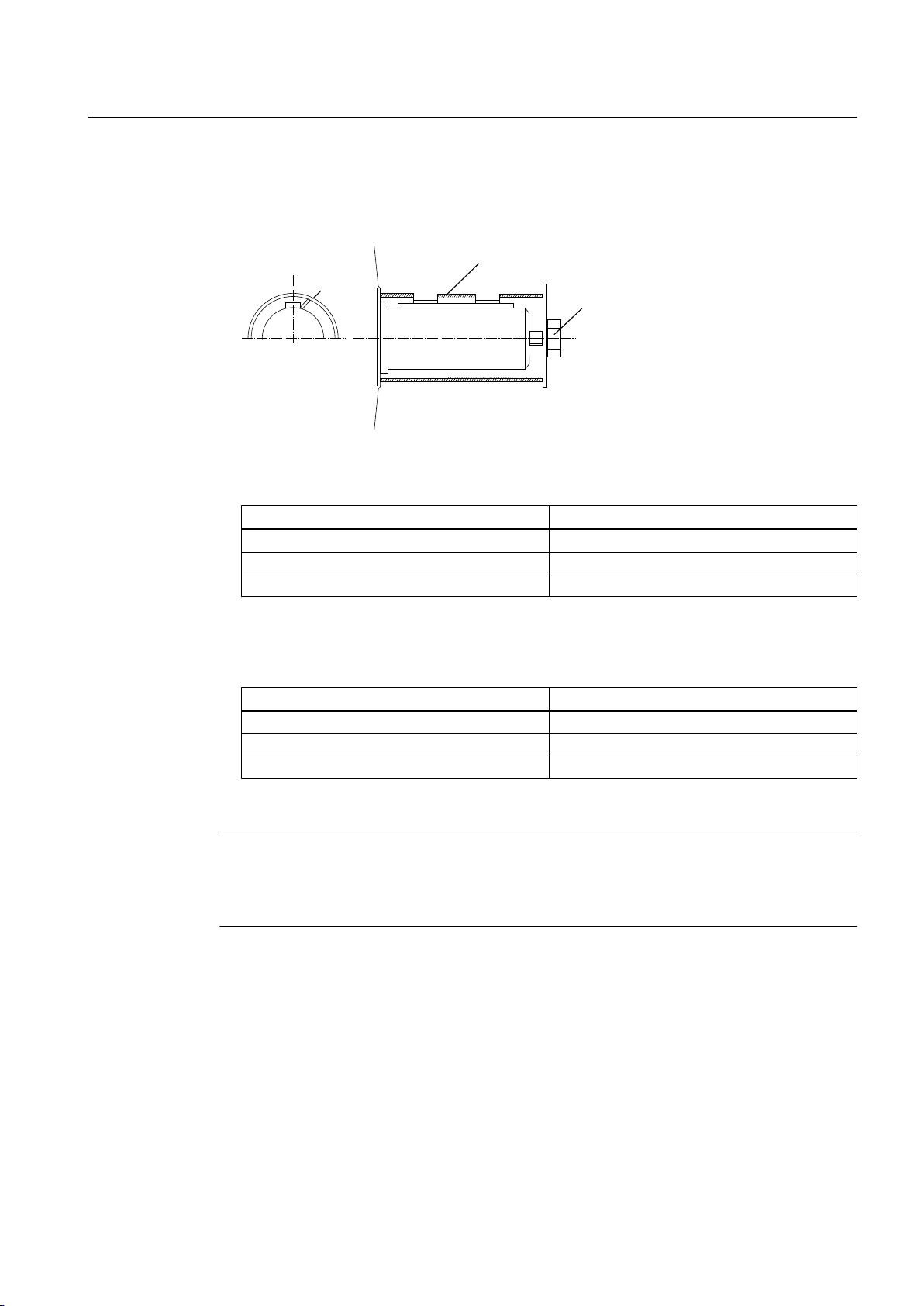
Alternative rotor bracing
ཱ
● If you transport the machine after the output element has been pulled on, then you must
axially fix the rotor in another way.
① Sleeve ② Shaft screw and washer
Figure 4-1 Axial fastening of the rotor
Thread in the shaft extension Tightening torque
M20 80 Nm
M24 150 Nm
M30 230 Nm
Preparations for use
4.18 Transport and storage
Tightening torques for other rotor shipping brace types
● The thread in the shaft extension indicates the rotor weight. This indirectly specifies the
required preload force when axially fastening the rotor.
Thread in the shaft extension Preload
M20 20 kN
M24 30 kN
M30 40 kN
Axial preload force for other rotor shipping brace types
Note
Store the rotor locking device
Be sure to store the rotor locking device. It must be remounted for possible disassembly and
transport.
SIMOTICS FD 1MH1
Operating Instructions 08/2017 47
Page 48
Preparations for use
4.18 Transport and storage
4.18.4 Transporting the machine set
WARNING
Falling down of the machine
The lifting lugs on the machine are designed only for the weight of the machine. If a machine
set is lifted and transported on a single machine, this can lead to mechanical failure of the
lifting lug. The machine or machine set may fall. This can result in death, serious injury or
material damage.
● Do not lift machine sets by attaching lifting tackle to the individual machines.
● Use only the equipment provided, e.g. the openings or lugs on the base plates, for
transporting machine sets. Note the maximum capacity of the lifting lug.
Note
Place the machine in a secure and raised position
In order to obtain easy and safe access to the underside of the machine, place it in a secure
and raised position.
DANGER
Standing under suspended loads
If the lifting gear or load handling attachments were to fail, the machine could fall. This can
result in death, serious injury or material damage.
● Never remain under or in the immediate vicinity of the machine when it is raised.
4.18.5 Storage
You must correctly store the machine if you do not install and use it after it has been delivered.
NOTICE
Bearing seizure damage if incorrectly stored
If storage conditions are inappropriate there is a risk of bearing seizure damage. Resulting
damage can include scoring (brinelling) and corrosion.
● Follow the storage guidelines.
Preconditions and preparations
● Only store goods in undamaged packaging. Unpack the goods if the packaging is damaged.
Correctly store the goods corresponding to the type.
● Repair any damage to the packaging before putting the equipment into storage insofar as
this is necessary to ensure proper storage conditions.
SIMOTICS FD 1MH1
48 Operating Instructions 08/2017
Page 49

General instructions for storage
Wherever possible, store the machine in a storage room. The place of storage must satisfy
the following general conditions:
● Select a sufficiently sized dry and horizontal place of storage that is above flood level and
free of vibration (v
– The place of storage must be well ventilated as well as free of dust and frost. Provide
protection against extreme weather conditions. Ensure that the temperature remains
stable in the range from 10 °C to 50 °C – or 50 °F to 120 °F. The room temperature
should be approx. 10 K above the outside temperature. The temperature should not fall
below ‑20° C.
– The relative humidity of the air should be less than 60%.
– The floor of the place of storage must be sufficiently strong. The maximum permissible
floor loading or storage compartment loading may not be exceeded.
– The ambient air must not contain any harmful gases.
● Protect the machine from shocks and humidity.
● Position machines, devices and crates on pallets, wooden beams or foundations that
protect them against rising damp and water.
≤ 0.2 mm/s).
eff
Preparations for use
4.18 Transport and storage
● Ensure that the air circulation under the equipment is not impeded.
– Place wooden spacer blocks between the covers and the machine.
– Covers or tarpaulins must not trail on the floor around the machine.
Storing outdoors
When storing the machines outside, the storage location must comply with the following
conditions:
● The ground must be sufficiently strong. Prevent the machine from sinking into the ground.
● Covers or tarpaulins used to protect the equipment against the weather must not make
contact with the surfaces of the equipment. Otherwise air circulation under the stored items
will be prevented.
Protection against humidity
If a dry storage space is not available, protect the machine as follows against humidity:
● Wrap the machine in humidity-absorbent material.
● Wrap the machine in plastic film:
– Place a humidity meter inside the plastic film.
– Place desiccant within the plastic film.
– Pack the machine air-tight.
● Inspect the machine regularly.
SIMOTICS FD 1MH1
Operating Instructions 08/2017 49
Page 50
Preparations for use
4.18 Transport and storage
NOTICE
Improper storage or transport
Damage to bearings can result from improper storage or transport.
● On machines that have been supplied with a rotor shipping brace, secure the rotor as per
the notes on transportation (Page 46).
● Protect the motor against strong radial shocks and vibration when storing, as the rotor
shipping brace cannot completely absorb these forces.
● If the customer has already mounted parts, such as a coupling or belt pulley, the bearings
can be damaged during transport. In this case, make sure that the customer uses a rotor
locking device.
WARNING
Risk of explosion due to damaged sealing materials
Storing the machine at temperatures that do not fall within the specified limits can damage
the material of the seals and cause them to fail. As a result, a potentially explosive gaseous
atmosphere can enter the machine and be ignited during commissioning. Explosions can
occur. This can result in death, serious injury or material damage.
The materials used are specially designed for the temperature range required by the
customer. Do not store the machine in conditions that lie outside the specified temperature
limits. The relevant temperature limits are specified on the rating plate.
Long-term storage
If you are storing a machine for more than six months, you must check its condition every six
months. Store the machine in accordance with the specifications in Section "Storage
(Page 48)", and if possible, packed.
● Check the motor for damage.
● Carry out any necessary maintenance work.
● Make sure that the storage conditions are such that condensation cannot form in the motor.
● If the machine is not sealed in plastic film, continually and slightly heat the machine, e.g.
with anti-condensation heating (if available), and ensure that the air circulates in the storage
room.
Storage for longer than three months
Lubricate the machine after every two years of storage.
1. Unpack the machine.
2. Remove the rotor shipping brace, if one is being used.
SIMOTICS FD 1MH1
50 Operating Instructions 08/2017
Page 51

3. When stored for longer than two years, lubricate with twice the grease quantity in
accordance with the lubricant plate. This ensures that the grease is evenly distributed and
covers all surfaces. Corrosion damage is avoided.
NOTICE
Damage to roller bearings
Roller bearings can be damaged when kept in the same or almost the same position.
Every three months, manually rotate the rotor through five revolutions. Make sure that the
resting position of the roller bearings after the rotor has been turned is different from what
it previously had been. Use the feather key as a reference point, if present.
4. Replace the corrosion protection.
5. Reattach the rotor shipping brace, if present.
6. Pack the machine again.
4.18.6 Protecting the cooling water circuit during storage
Preparations for use
4.18 Transport and storage
When supplied, the machine is not filled with cooling water.
Protecting the cooling circuit against corrosion
You protect the cooling circuit against corrosion when the machine has already been in
operation and is then placed in storage or put out of operation.
1. Completely drain the cooling ducts. Blow out the cooling water ducts with compressed air.
1. Close and seal the intake and discharge.
4.18.7 Protection against corrosion
If the machine is stored in dry conditions, then apply the subsequently listed anti-corrosion
measures:
● Storage up to six months:
Apply a coat of corrosion protective compound to all accessible bare metal parts such as
the exposed shaft extension, flange or machine feet.
● Storage for longer than six months:
Apply a coat of long-term anti-corrosion agent to all accessible bare parts.
● Inspect the machine regularly and if necessary, apply an additional coating of corrosion
protection.
Document all preservation measures taken so that they can be reversed before the machines
are put back into service.
SIMOTICS FD 1MH1
Operating Instructions 08/2017 51
Page 52
Preparations for use
4.19 Converter operation
4.19 Converter operation
The following chapter is relevant only if the machine has been ordered for converter operation.
Note
The order number shows whether the machine was ordered for converter operation. In this
case, digits 1, 2, 3 or 4 is located at the 6th position of the order number.
4.19.1 Converter operation of explosion-proof machines
The operation of the explosion-proof machine on the frequency converter is permitted, when
the specifications for the speed control range and torque characteristic are observed, and if
winding temperature monitoring is ensured via the integrated temperature sensors in
conjunction with a tripping unit.
WARNING
Operation with a converter that is not permissible for the application
If a certain converter type has been defined in the test verification document, on the extra
rating plate, or in the certificate, the machine is only allowed to be operated with this converter.
Death, serious injury, or material damage can result if it is operated with an unauthorized
converter.
● Only operate the motor with the specified converter.
4.19.2 Supply line configuration
NOTICE
Asymmetric voltage load during operation on a TN system in delta connection
An asymmetric voltage load of the machine winding can occur during operation on a TN
system in delta connection with a grounded line conductor. Winding damage can result.
● Do not operate the machine on a TN system with a grounded line conductor.
NOTICE
Ground fault during operation on an IT system
If a ground fault occurs when connected to an IT supply system, the insulation is excessively
stressed. Winding damage can result.
● If possible, complete the process within two hours.
● Rectify the fault cause.
● Deploy a ground fault monitoring.
SIMOTICS FD 1MH1
52 Operating Instructions 08/2017
Page 53

4.19.3 Converter input voltage
The insulation system of SIMOTICS machines significantly exceeds the requirements of stress
category C (IVIC C = high stress). If voltage peaks higher than those specified according to
IVIC C can occur, then observe the data in the respective Catalog (http://w3app.siemens.com/
mcms/infocenter/content/en/Pages/order_form.aspx):
● For a line voltage (converter input voltage) up to max. 480 V and operation connected to a
SINAMICS G / SINAMICS S converter with uncontrolled/controlled infeed: Comply with the
guidelines for configuring motor and converter.
● For line voltages (converter input voltages) higher than 480 V, motors, which are ordered
for converter operation, have an appropriate insulation system.
● Operation with a converter from another manufacturer: Comply with the permissible voltage
peaks according to IEC 60034-18-41 in accordance with stress category C, dependent on
the particular line voltage (converter input voltage) and the motor insulation system.
NOTICE
Material damage caused by an excessively high supply voltage
The insulation system will be damaged if the supply voltage is too high for the insulation
system. This can completely destroy the machine.
● Comply with the peak voltages as laid down in the guidelines above.
Preparations for use
4.19 Converter operation
4.19.4 Reducing bearing currents
Taking the following actions will reduce the bearing currents:
● Ensure that the contacts are established over a large area. Solid copper cables are not
suitable for high frequency grounding because of the skin effect.
Equipotential bonding conductors:
Use equipotential bonding conductors:
● Between motor and driven machine
● Between motor and converter
● Between the terminal box and the RF grounding point at the motor enclosure.
SIMOTICS FD 1MH1
Operating Instructions 08/2017 53
Page 54
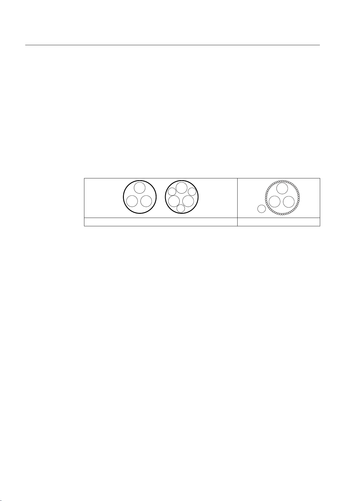
/
3(
3(
3(
/
//
//
3(
/
/
/
Preparations for use
4.19 Converter operation
Selecting and connecting the cable:
As far as possible, use symmetrically arranged, shielded connection cables. The cable
shielding, made up of as many strands as possible, must have good electrical conductivity.
Braided shields made of copper or aluminum are very suitable.
● The shield is connected at both ends, at the motor and converter.
● To ensure good discharging of high-frequency currents, provide contacting over a large
surface area:
– as contact established through 360° at the converter
– at the motor, for instance with EMC glands at the cable entries
● If the cable shield is connected as described, then it ensures the specified equipotential
bonding between the motor enclosure and converter. A separate RF equipotential bonding
conductor is then not necessary.
● If the cable shield is not connected due to special secondary conditions, or not adequately
connected, then the specified equipotential bonding is not provided. In this particular case,
use a separate RF equipotential bonding conductor:
– Between the motor enclosure and protective ground rail of the converter.
– Between motor enclosure and driven machine
– Use braided flat copper straps or high-frequency cables with finely-stranded conductors
– Ensure that the contacts are established over a large area.
Overall system design
To specifically reduce bearing currents, you must consider the system as a whole, which
comprises the motor, converter, and driven machine. The following measures support you
when reducing bearing currents and help to avoid damage:
● In the overall system, set up a properly meshed grounding system with low impedance.
● Use the common-mode filter (damping cores) at the converter output. The Siemens sales
representative is responsible for selection and dimensioning.
● Limit the rise in voltage by using output filters. Output filters dampen the harmonic content
in the output voltage.
Concentric copper or aluminum shield Steel armor
for the separate RF equipotential bonding cable.
54 Operating Instructions 08/2017
SIMOTICS FD 1MH1
Page 55
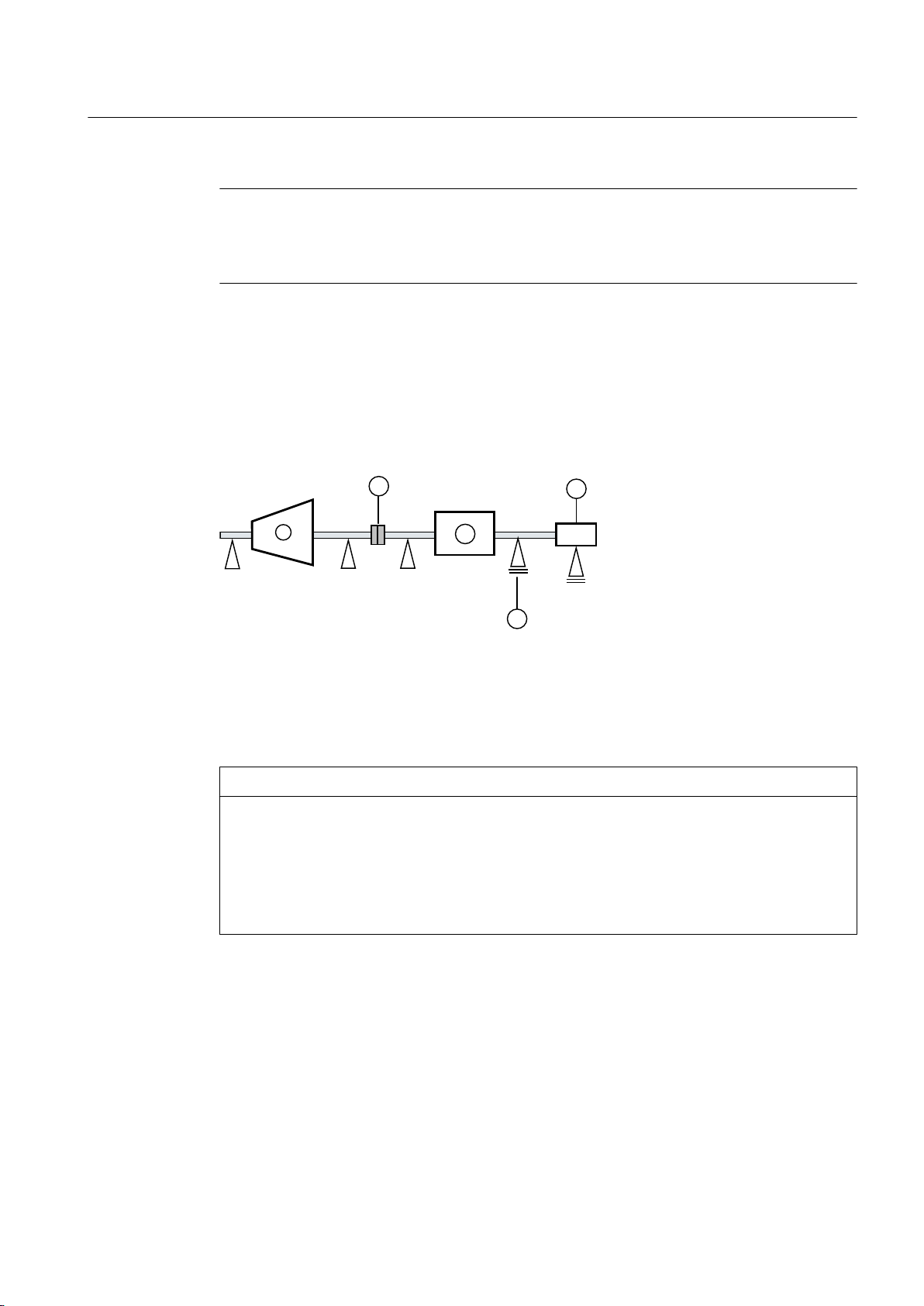
Note
Converter documentation
The operating instructions for the converter are not part of this documentation. Refer also to
the configuration information for the converter.
4.19.5 Insulated bearings when operating the converter
If the machine is operated from a low-voltage converter, insulated bearings are fitted at the
NDE and an insulated encoder with insulated bearings (option).
Comply with the plates on the machine relating to bearing insulation and possible bridges.
Preparations for use
4.19 Converter operation
① Driving machine ④ Insulated bearings
② Motor ⑤ Insulated tachometer fitting
③ Coupling
Figure 4-2 Schematic representation of a single drive
NOTICE
Bearing damage
The bearing insulation must not be bridged. Bearing currents can damage bearings.
● Also for subsequent installation work, such as the installation of an automatic lubrication
system or a non-insulated vibration sensor, make sure that the bearing insulation cannot
be bridged.
● Contact the Service Center, if necessary.
SIMOTICS FD 1MH1
Operating Instructions 08/2017 55
Page 56
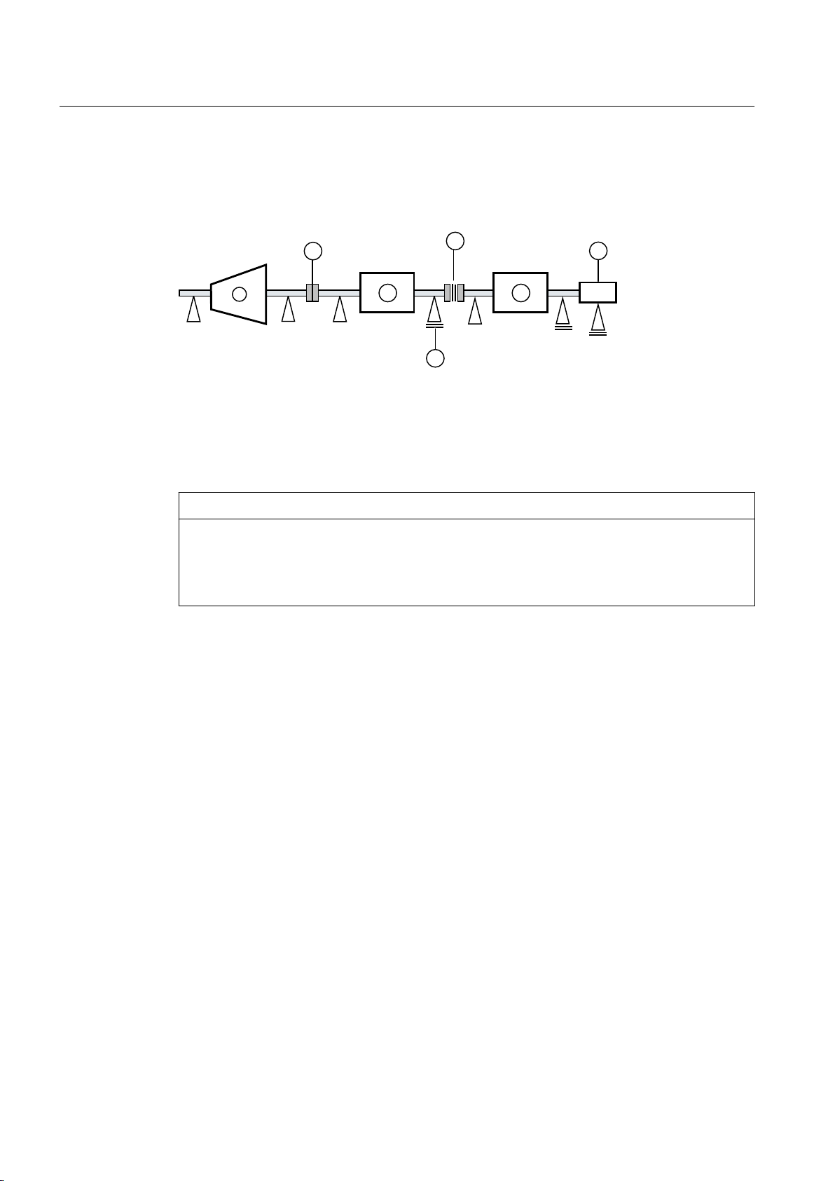
Preparations for use
4.19 Converter operation
Tandem operation
If you connect two motors in series in "tandem operation", install an insulated coupling between
the motors.
① Driving machine ④ Insulated bearings
② Motor ⑤ Insulated tachometer fitting
③ Coupling ⑥ Insulated coupling
Figure 4-3 Schematic representation of a tandem drive
See also
NOTICE
Bearing damage
Bearing currents can flow if the coupling between the motors of the tandem drive is not
insulated. This can damage the DE bearings of both motors.
● Use an insulated coupling to link the motors.
Service and Support (Page 177)
If you connect two motors in series in "tandem operation", locate a coupling between the
motors; this coupling should satisfy the Directive 2014/34/EU or the regulations that apply in
the country where the equipment is installed.
56 Operating Instructions 08/2017
SIMOTICS FD 1MH1
Page 57

4.19.6 Converter operation on a grounded network
NOTICE
Damage resulting from protective conductor currents
When the machine is operated on a converter with current limiter, but without ground-fault
monitoring, protective conductor currents of up to 1.7 times the external conductor current
can arise if there is a ground fault on the output side. Neither the PE conductors of normally
rated multi-core connecting cables nor the PE connecting points of normal terminal boxes
are suitable for this purpose. Material damage can result.
● Use an appropriately sized PE conductor.
● Connect the PE conductor to the grounding terminal on the motor enclosure.
Preparations for use
4.19 Converter operation
SIMOTICS FD 1MH1
Operating Instructions 08/2017 57
Page 58

Preparations for use
4.19 Converter operation
SIMOTICS FD 1MH1
58 Operating Instructions 08/2017
Page 59
Assembly
See also
5
Observe the following when carrying out any work on the machine:
● Comply with the general safety instructions
● Comply with the applicable national and sector-specific regulations at the place of
installation
● When using the machine within the European Union, comply with the specifications laid
down in EN 50110‑1 regarding safe operation of electrical equipment.
Safety information (Page 15)
Note
Loss of conformity with European directives
In the delivery state, the machine corresponds to the requirements of the European directives.
Unauthorized changes or modifications to the machine lead to the loss of conformity with
European directives and the loss of warranty.
See also
WARNING
Explosion hazard when making modifications to the machine
Substantial modifications to the machine are not permitted – or may only be performed by
the manufacturer. Otherwise an explosion can occur in an explosive atmosphere. This can
result in death, serious injury or material damage.
Please contact the Service Center, if necessary.
Service and Support (Page 177)
SIMOTICS FD 1MH1
Operating Instructions 08/2017 59
Page 60

Assembly
5.1 Preparations for installation
5.1 Preparations for installation
5.1.1 Requirements for installation
The following requirements must be satisfied prior to starting installation work:
● Staff have access to the operating and installation instructions.
● The machine is unpacked and ready for mounting at the installation location.
Note
Measure the insulation resistance of the winding before starting installation work
Measure the insulation resistance of the winding before starting any installation work. If the
insulation resistance lies below the specified value, take appropriate remedial measures.
These remedial measures may necessitate the machine being removed again and
transported.
NOTICE
High temperatures
The motor components get very hot during operation. High temperatures can damage parts
mounted by customers, such as cables manufactured out of materials that are not heat
resistant.
● Temperature-sensitive parts must not come in contact with or be attached to components
mounted on the machine.
● Only use heat-resistant mounting parts. The connecting cables and cable entries must be
suitable for the particular application.
5.1.2 Insulation resistance and polarization index
Measuring the insulation resistance and polarization index (PI) provides information on the
condition of the machine. It is therefore important to check the insulation resistance and the
polarization index at the following times:
● Before starting up a machine for the first time
● After an extended period in storage or downtime
● Within the scope of maintenance work
The following information is provided regarding the state of the winding insulation:
● Is the winding head insulation conductively contaminated?
● Has the winding insulation absorbed moisture?
SIMOTICS FD 1MH1
60 Operating Instructions 08/2017
Page 61
As such, you can determine whether the machine needs commissioning or any necessary
measures such as cleaning and/or drying the winding:
● Can the machine be put into operation?
● Must the windings be cleaned or dried?
Detailed information on testing and the limit values can be found here:
"Testing the insulation resistance and polarization index" (Page 61)
5.1.3 Testing the insulation resistance and polarization index
WARNING
Hazardous voltage at the terminals
During and immediately after measuring the insulation resistance or the polarization index
(PI) of the stator winding, hazardous voltages may be present at some of the terminals.
Contact with these can result in death, serious injury or material damage.
● If any power cables are connected, check to make sure line supply voltage cannot be
delivered.
● Discharge the winding after measurement until the risk is eliminated, e.g. using the
following measures:
– Connect the terminals with the ground potential until the recharge voltage drops to a
non-hazardous level
– Attach the connection cable.
Assembly
5.1 Preparations for installation
Measure the insulation resistance
1. Before you begin measuring the insulation resistance, please read the operating manual
for the insulation resistance meter you are going to use.
2. Make sure that no power cables are connected.
3. Measure the winding temperature and the insulation resistance of the winding in relation
to the machine enclosure. The winding temperature should not exceed 40° C during the
measurement. Convert the measured insulation resistances in accordance with the formula
to the reference temperature of 40° C. This thereby ensures that the minimum values
specified can be compared.
4. Read out the insulation resistance one minute after applying the measuring voltage.
SIMOTICS FD 1MH1
Operating Instructions 08/2017 61
Page 62
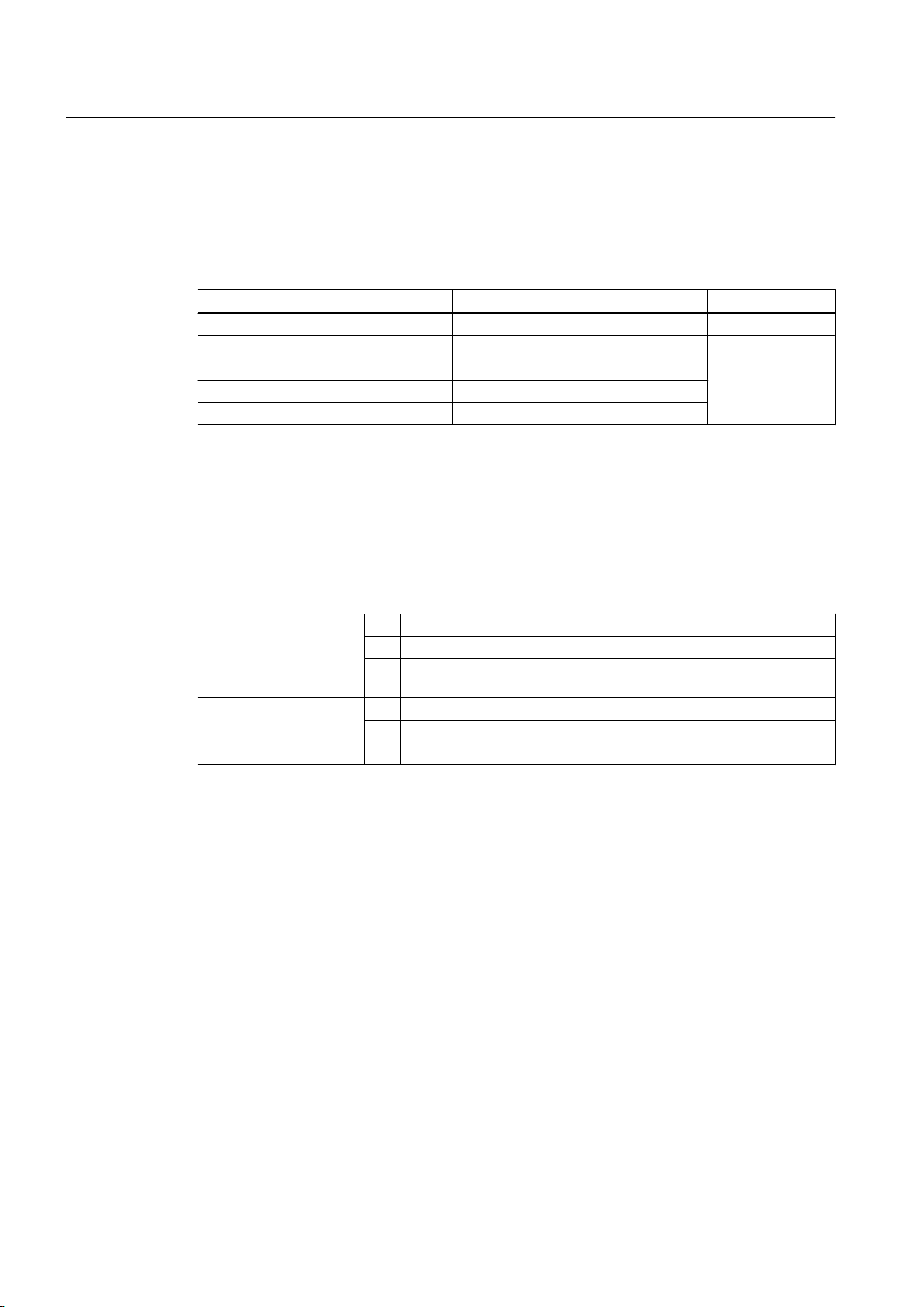
Assembly
5.1 Preparations for installation
Limit values for the stator winding insulation resistance
The following table specifies the measuring voltage and limit values for the insulation
resistance. These values correspond to IEEE 43‑2000 recommendations.
Table 5-1 Stator winding insulation resistance at 40° C
VN [V] V
U ≤ 1000 500 ≥ 5
1000 ≤ U ≤ 2500 500 (max. 1000) 100
2500 < U ≤ 5000 1000 (max. 2500)
5000 < U ≤ 12000 2500 (max. 5000)
U > 12000 5000 (max. 10000)
U
= rated voltage, see the rating plate
rated
U
= DC measuring voltage
meas
RC = minimum insulation resistance at reference temperature of 40° C
Conversion to the reference temperature
When measuring with winding temperatures other than 40° C, convert the measuring value to
the reference temperature of 40° C according to the following equations from IEEE 43-2000.
(1)
RC = KT · R
(2)
KT = (0.5)
T
(40-T)/10
[V] RC [MΩ]
Meas
RCInsulation resistance converted to 40° C reference temperature
kTTemperature coefficient according to equation (2)
RTMeasured insulation resistance for measuring/winding temperature T
in °C
40 Reference temperature in °C
10 Halving/doubling of the insulation resistance with 10 K
T Measuring/winding temperature in °C
In this case, doubling or halving the insulation resistance at a temperature change of 10 K is
used as the basis.
● The insulation resistance halves every time the temperature rises by 10 K.
● The resistance doubles every time the temperature falls by 10 K.
For a winding temperature of approx. 25° C, the minimum insulation resistances are 20 MΩ
(U ≤ 1000 V) or 300 MΩ (U > 1000 V). The values apply for the complete winding to ground.
Twice the minimum values apply to the measurement of individual assemblies.
● Dry, new windings have an insulation resistance of between 100 and 2000 MΩ, or possibly
even higher values. An insulation resistance value close to the minimum value could be
due to moisture and/or dirt accumulation. The size of the winding, the rated voltage and
other characteristics affect the insulation resistance and may need to be taken into account
when determining measures.
● Over its operating lifetime, the motor winding insulation resistance can drop due to ambient
and operational influences. Calculate the critical insulation resistance value depending on
the rated voltage by multiplying the rated voltage (kV) by the specific critical resistance
value. Convert the value for the current winding temperature at the time of measurement,
see above table.
SIMOTICS FD 1MH1
62 Operating Instructions 08/2017
Page 63
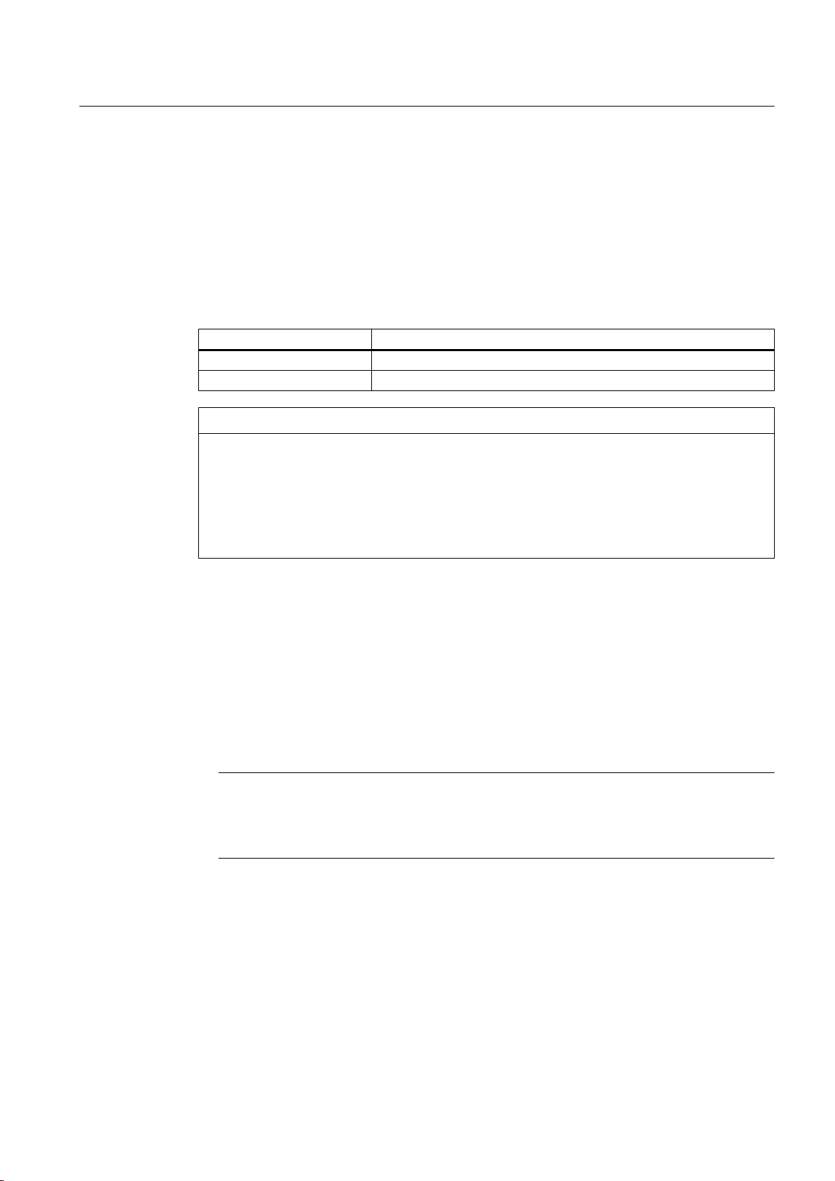
Measuring the polarization index
1. To determine the polarization index, measure the insulation resistances after one minute
and ten minutes.
2. Express the measured values as a ratio:
PI = R
insul 10 min
Many measuring devices display these values automatically following the measurement.
For insulation resistances > 5000 MΩ, the measurement of the PI is no longer meaningful and
consequently not included in the assessment.
R
/ R
(10 min)
≥ 2 Insulation in good condition
< 2 Dependent on the complete diagnosis of the insulation
NOTICE
Damage to insulation
If the critical insulation resistance is reached or undershot, this can damage the insulation
and cause voltage flashovers.
● Contact the Service Center (Page 177).
● If the measured value is close to the critical value, you must subsequently check the
insulation resistance at shorter intervals.
/ R
(1 min)
Assembly
5.1 Preparations for installation
insul 1 min
Assessment
Limit values of the anti-condensation heating insulation resistance
The insulation resistance of the anti-condensation heating with respect to the machine housing
should not be lower than 1 MΩ when measured at 500 V DC.
5.1.4 Prepare the mating faces (IM B3)
● Ensure that the foundation faces are flat and free of contaminations.
Note
Shims
To establish a defined mounting surface, you can order shims (option L31) from our Service
Center.
● Check the dimensions of the mounting-foot holes.
See also
Lifting and transportation (Page 45)
Service and Support (Page 177)
SIMOTICS FD 1MH1
Operating Instructions 08/2017 63
Page 64

Assembly
5.2 Lift the machine to where it will be installed, and position it
5.1.5 Prepare the mating face for a flange connection
● Clean the flange before installation, and make sure that the flange face is flat and free of
contaminations.
● Check the geometry of the flange.
See also
Lifting and transportation (Page 45)
5.1.6 Prepare the mating face for wall mounting
● Ensure that the wall surface is flat and free of contaminations.
● Check the dimensions of the mounting-foot holes.
● Support the machine from below, e.g. using a wall bracket or by bolting it.
5.2 Lift the machine to where it will be installed, and position it
5.2.1 Preconditions for correct alignment and secure attachment
Detailed specialist knowledge of the following measures is required in order to correctly align
and securely fit the equipment.
● Preparing the foundation
● Selecting and mounting the coupling
● Measuring the concentricity and axial eccentricity tolerances
● Positioning the machine
If you are not familiar with the prescribed measures and procedures, then you can make use
of the services offered by the local Service Center (Page 177).
SIMOTICS FD 1MH1
64 Operating Instructions 08/2017
Page 65
5.2 Lift the machine to where it will be installed, and position it
5.2.2 Checking the load handling attachments
Inspect the load handling attachments such as the load trestles, lifting eyes and ring bolts and
also the lifting gear, before lifting the machine:
● Inspect the load handling attachments on the machine for possible damage. Replace any
load suspension equipment that is found to be damaged.
● Before use, check that the load suspension equipment is correctly attached.
● When lifting the machine, use only approved and undamaged lifting gear of sufficient rated
capacity. Check the lifting gear prior to its use.
WARNING
The machine can be dropped
If the load handling attachments and lifting gear are damaged or not correctly secured,
the machine may be dropped during lifting. This can result in death, serious injury or
material damage.
● Inspect the load handling attachments and lifting gear before use.
Assembly
5.2.3 Removing the rotor shipping brace
If a rotor shipping brace is attached to the machine, remove it at the last possible moment,
for example, when you are ready to push on the output or drive element.
5.2.4 Removing the rotor shipping brace from machines in vertical type
NOTICE
Removing the rotor shipping brace in the horizontal position.
Dismantling the rotor shipping brace when the machine is in a horizontal position could
damage the bearings.
● Only remove the rotor shipping brace when the machine is in a vertical position.
NOTICE
Turning the motor over without rotor shipping brace
Failure to fit the rotor shipping brace can result in damage to the bearings while the machine
is being turned onto its side.
● Fix the rotor in place before you turn the machine into a horizontal position.
SIMOTICS FD 1MH1
Operating Instructions 08/2017 65
Page 66

Assembly
5.2 Lift the machine to where it will be installed, and position it
Note
Store the rotor locking device
Be sure to store the rotor locking device. It must be remounted for possible disassembly and
transport.
5.2.5 Removing anti-corrosion protection
Machined, bare metallic surfaces of the motor, such as the shaft end, fitted key, foot and flange
surfaces, are treated with an anti-corrosion agent.
1. Remove this layer of anti-corrosion agent from the mounting surfaces of the motor by wiping
it away with an absorbent cloth or paper sheet.
NOTICE
Damage to the machine surface
Using metal objects such as scrapers, spatulas, or plates to remove the anti-corrosion
protection could result in damage to the surfaces of the machine parts.
2. Then lightly oil the bare surfaces again.
5.2.6 Mounting the output elements
Balance quality
The rotor is dynamically balanced. For shaft extensions with featherkeys, the balancing type
is specified using the following coding on the face of the drive end of the shaft:
● "H" means balancing with a half feather key
● "F" means balancing with a whole feather key
Figure 5-1 Balancing type on the drive-end side
SIMOTICS FD 1MH1
66 Operating Instructions 08/2017
Page 67

Pushing on the power output elements
● Requirements:
– The coupling and/or the output element must be appropriately dimensioned for the
operating case at hand.
– Comply with the coupling manufacturer's instructions.
– Make sure that the balancing type of the transmission element correctly matches the
type of balance of the rotor.
– Use only ready drilled and balanced transmission elements. Check the hole diameters
and the balancing status before pulling them on. Thoroughly clean the shaft extension.
● Pulling on:
– Warm up the transmission elements to expand them before pulling them on. Select the
temperature difference for the heating process to suit the coupling diameter, fit and
material. See the coupling manufacturer's instructions.
– Power output elements may only be pushed on or pulled off with the correct equipment.
The transmission element must be pulled on in one continuous operation via the front
thread holes in the shaft or pushed on by hand.
Assembly
5.2 Lift the machine to where it will be installed, and position it
– Do not strike it with a hammer, as this would damage the bearings.
Shaft extensions with feather key
To maintain the balancing quality, you have the following options:
● If the transmission element is shorter than the feather key with balancing type "H", then you
must machine off the section of feather key protruding from the shaft contour and
transmission element in order to maintain the balance quality.
● If the transmission element is drawn up on to the shoulder of the shaft, you must ensure
that the part of the coupling groove where the feather key is not inserted is taken into
consideration when balancing the coupling.
The following applies to all four-pole machines with a frequency ≥ 60 Hz:
● The feather key must be shortened if the coupling hub us shorter than the feather key.
● The center of gravity of the coupling half should be within the length of the shaft end.
● The coupling used must be prepared for system balancing.
The number of poles of the machine is specified on the rating plate, at the 10th position of
the motor type. There, four-pole machines are marked with a "B".
SIMOTICS FD 1MH1
Operating Instructions 08/2017 67
Page 68
Assembly
5.2 Lift the machine to where it will be installed, and position it
WARNING
The feather key can fall out
The feather keys are only locked against falling out during shipping. If a machine with two
shaft extensions does not have an output element on one shaft extension, the feather key
can fall out during operation.
Death or serious injury can result.
● Do not operate the machine unless the transmission elements have been pulled on.
● On shaft extensions without output element, make sure that the feather key cannot fall
out and shorten it by approximately half for balance type "H".
5.2.7 Lifting and transportation
To safely lift and transport the machine, the following requirements must be met:
● Personnel operating cranes and fork-lift trucks must be appropriately qualified.
● If the machine is packed, depending on the weight, size and on-site conditions, lift crates
and transport frames using a fork-lift truck or a crane with slings. Use a crane or fork-lift
truck suitable for the load.
● When lifting the machine, use only approved and undamaged sling guides and spreaders
of sufficient rated capacity. Check the lifting equipment prior to its use. The weight of the
machine is shown on the rating plate.
● When lifting the machine, refer to the information on the lifting plate.
– Comply with the specified spreading angles.
– Do not exceed the maximum lifting acceleration and lifting speed specified on the lifting
plate. Lift the machine without jerking it.
Acceleration a ≤ 0.4 g (≈ 4 m/s2 )
Velocity v ≤ 20 m/min
WARNING
Transport for a different type of construction
If you do not transport or lift the machine in a position appropriate for its construction, the
machine can tip, slip into the lifting equipment or fall down. This can result in death, serious
injury or material damage.
● Use only the load carrying device on the stator frame for lifting.
● Use the load carrying device appropriate for the machine position.
● Only use suitable rope guiding or spreading devices.
SIMOTICS FD 1MH1
68 Operating Instructions 08/2017
Page 69
Assembly
5.2 Lift the machine to where it will be installed, and position it
WARNING
Center of gravity not centered
If the center of gravity of a load is not located centrally between the attachment points, the
machine can tip over or slip out of the lifting equipment and fall when it is being transported
or lifted. This can result in death, serious injury or material damage.
● Comply with the handling instructions on the machine when transporting it.
● Be aware of the possibility of different loads on the sling ropes or lifting straps and the
carrying capacity of the lifting equipment.
● Always take account of the center of gravity when transporting or lifting the machine. If
the center of gravity is not located centrally between the attachment points, then position
the hoisting hook above the center of gravity.
Note
Place the machine in a secure and raised position
In order to obtain easy and safe access to the underside of the machine, place it in a secure
and raised position.
DANGER
Standing under suspended loads
If the lifting gear or load handling attachments were to fail, the machine could fall. This can
result in death, serious injury or material damage.
● Never remain under or in the immediate vicinity of the machine when it is raised.
5.2.8 Putting the machine down
Requirements
The following preconditions must be satisfied before setting down the machine at the
installation location:
● The mating faces must be clean.
● The anti-corrosion protection paint has been removed from the mating faces, such as the
machine mounting feet, flange, ...
● There is no condensation present within the machine.
Setting down the machine
● Set down the machine slowly and carefully at the installation location to avoid any impact.
SIMOTICS FD 1MH1
Operating Instructions 08/2017 69
Page 70
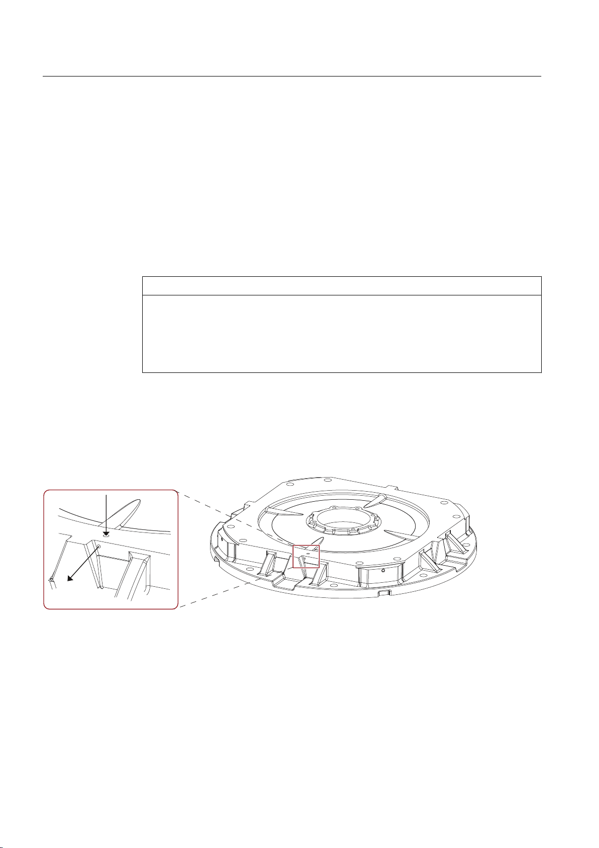
Assembly
5.2 Lift the machine to where it will be installed, and position it
See also
Draining condensation (Page 70)
5.2.9 Draining condensation
Under the following conditions it is possible that condensate may accumulate within the
machine:
● Wide fluctuations in the ambient temperature, such as direct sunshine combined with high
atmospheric humidity
● Intermittent operation or load fluctuations during operation
NOTICE
Damage due to condensate
If the stator winding is damp, its insulation resistance will be reduced. This can result in
voltage flashovers, which can destroy the winding. Condensate can also cause rust to
form within the machine.
Ensure that condensate can drain away.
Depending on the type of installation, the water drainage holes are located at the bottom:
Allow the condensation water to discharge for vertical placement
In the DE bearing shield, water drain holes are located in the area of the mounting feet or
opposite the regreasing system. They are sealed with screw plugs.
Figure 5-2 Condensation water drain for vertical mounting
SIMOTICS FD 1MH1
70 Operating Instructions 08/2017
Page 71
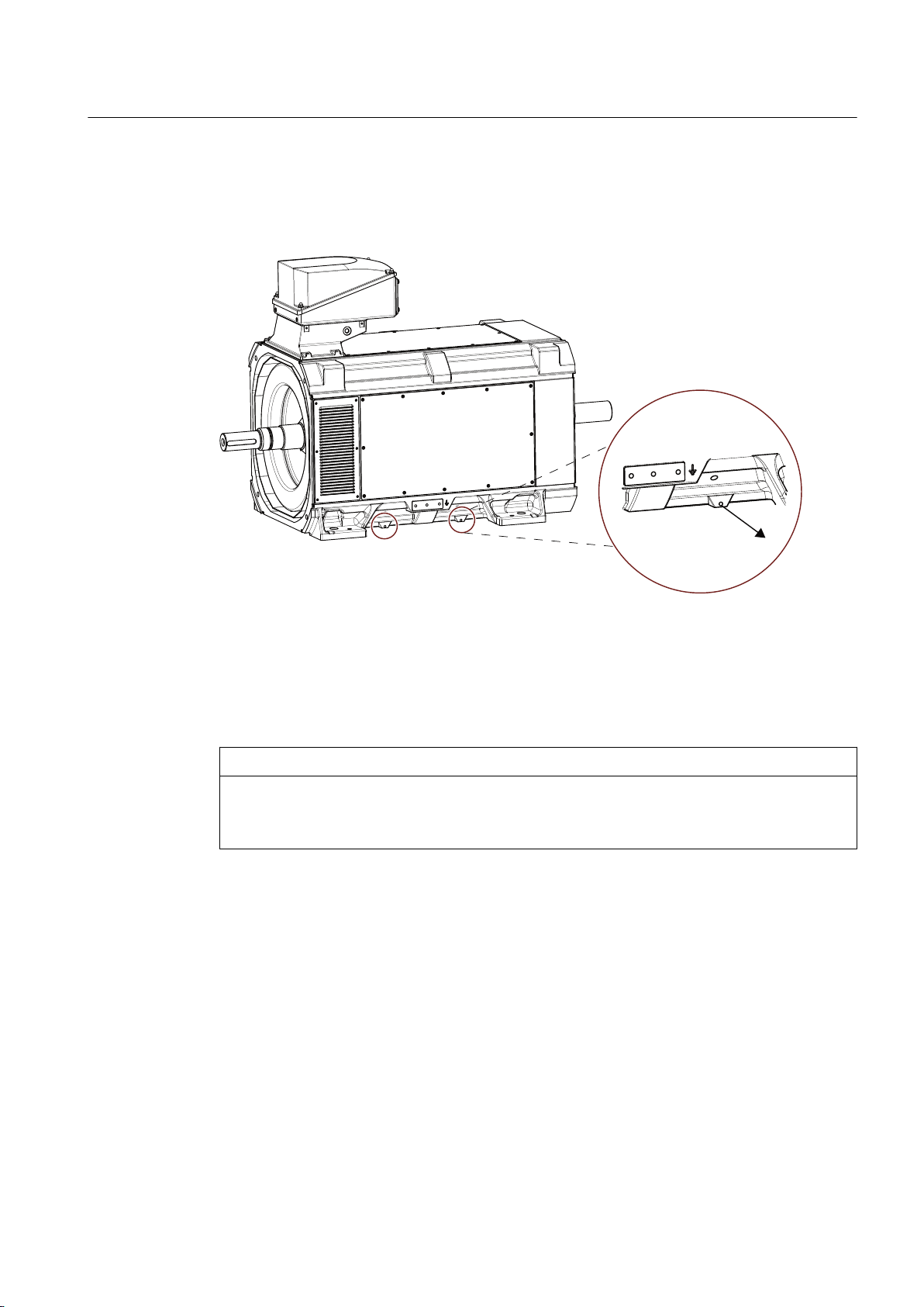
5.2 Lift the machine to where it will be installed, and position it
Allow the condensation water to discharge for horizontal placement
The water drain holes are located in the lower side of the stator enclosure, and sealed with
screw plugs.
Assembly
Figure 5-3 Condensation water drain for horizontal mounting
To drain the condensation water, proceed as follows:
1. Remove the screw plugs to allow the condensation water to drain.
2. Then reinsert the screw plugs.
NOTICE
The degree of protection is reduced
Nominally the degree of protection of the machine is reduced to IP44 when the screw plug is
removed.
5.2.10 Roughly aligning the machine
Requirement
The transmission element such as a coupling half has already been pulled on.
Roughly aligning the machine
● For horizontal positioning, push the motor sideways across the foundation. When doing so,
ensure that the axial position is maintained.
SIMOTICS FD 1MH1
Operating Instructions 08/2017 71
Page 72
Assembly
5.3 Installing the machine
5.3 Installing the machine
5.3.1 Safety instructions for installation
WARNING
Inappropriate fastening material
If screws of an incorrect property class have been selected or if they have been fastened to
an incorrect tightening torque, they may break or become loose. This will cause the machine
to move, which could damage the bearings. The rotor could smash into the machine enclosure
and machine parts could be flung out of place. This can result in death, serious injury or
material damage.
● Comply with the required property classes for screwed connections.
● Tighten the screwed connections to the specified tightening torques.
WARNING
Incorrect alignment
If the machine has not been properly aligned, this will mean the fastening parts are subjected
to stress/distortion. Screws may become loose or break, the machine will move, machine
parts could be flung out of place. This can result in death, serious injury or material damage.
● Carefully align the machine to the driven machine.
NOTICE
Improper handling
Mounting parts such as temperature sensors or speed sensors are attached to the machine
and could be ripped off or destroyed as a result of improper handling. This could lead to
machine malfunctions, extending even to total loss of the machine.
● Where necessary, use suitable steps when performing installation work on the machine.
● Do not stand on cables or attachments during installation. Do not use attachments as
steps.
5.3.2 Preconditions for smooth, vibration-free operation
Preconditions for smooth, vibration-free operation:
● Stable foundation design
● Precise alignment of the machine
● Correct balancing of parts to be fitted to the shaft end.
● Maintaining the vibration velocity according to ISO 10816‑3
SIMOTICS FD 1MH1
72 Operating Instructions 08/2017
Page 73
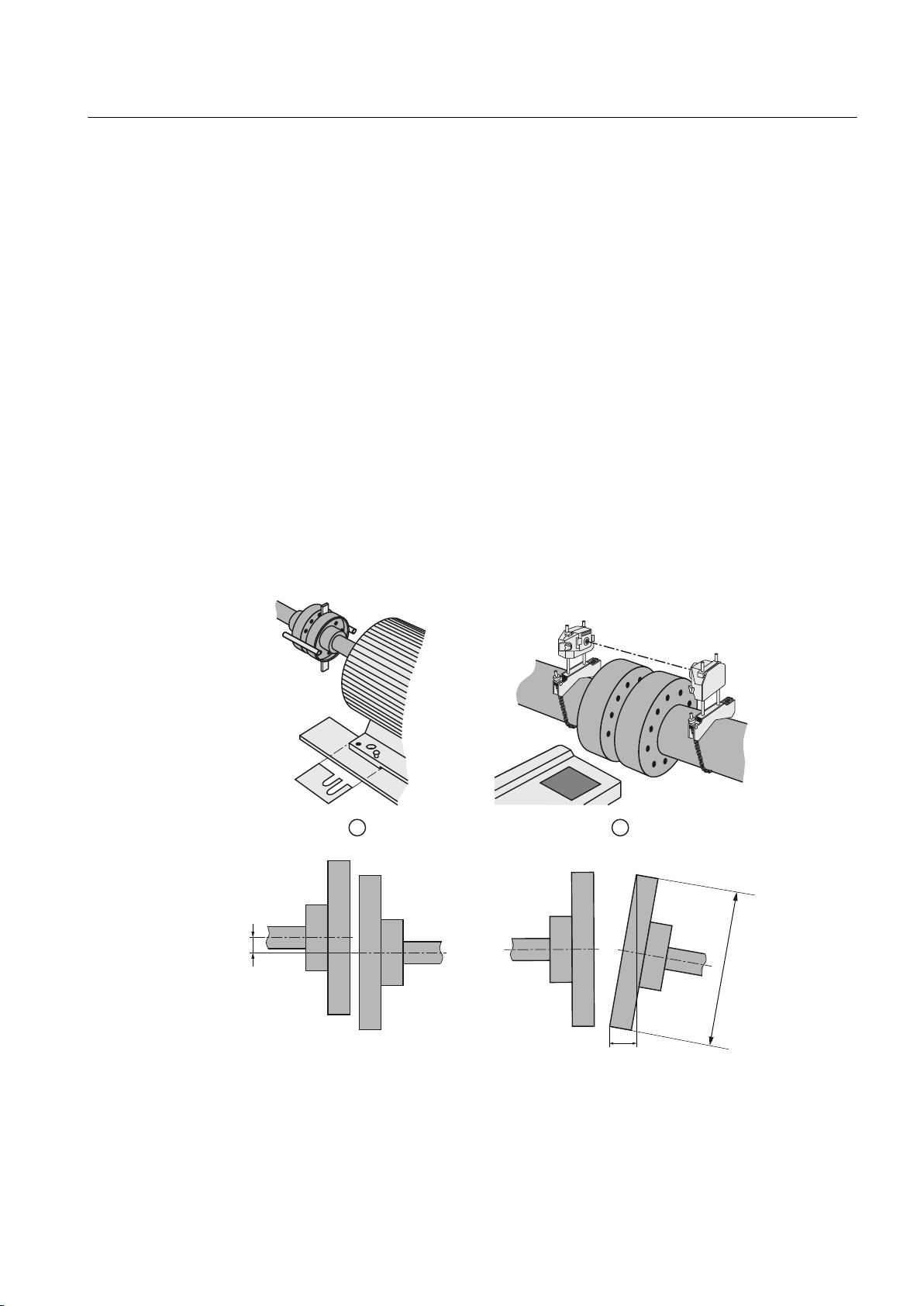
'
[
\
Assembly
5.3 Installing the machine
5.3.3 Aligning the machine to the driven machine and mounting (IM B3 / IM B35)
1. Refer to any instructions for aligning the driven machine and those of the coupling
manufacturer.
2. Align the machines with coupling output to the driven machine in such a manner that the
center lines of the shafts at the operating temperature do not have any parallel or angular
offset. This ensures that no additional forces affect their bearings during operation.
If the thermal change of the motor and the driven machine is different, couple in the cold
state with an appropriate alignment offset. The alignment offset to be set in the cold state
must be determined and specified by the system specialist.
3. For the vertical positioning (x→0), place thin shims over a large surface area under the
machine feet. The number of shims should be kept as low as possible, i.e. stack as few as
possible. This also prevents the machine being subjected to any stress/distortion. Use the
existing tapped holes for the forcing-off bolts to raise the machine.
The balance state of the shaft (full-key or half-key balancing) and alignment errors primarily
influence the service life of the bearing, especially for high motor speeds or when using
rigid couplings.
4. When positioning the machine, ensure that a uniform axial gap (y→0) is maintained around
the coupling.
5. Fix the machine to the foundation. The choice of fixing elements depends on the foundation
and is the plant operator's responsibility.
① Plates placed under the motor for alignment
② Laser alignment
Figure 5-4 Schematic diagram: Aligning the machine to the driven machine
SIMOTICS FD 1MH1
Operating Instructions 08/2017 73
Page 74

Assembly
5.3 Installing the machine
Table 5-2 Permissible deviations for aligning the machine with flexible coupling
Max. speed n
n
≤ 1500 rpm x
max
1500 rpm < n
max
≤ 3600 rpm x
max
Max. parallel offset x Max. angular offset y
= 0.08 mm y
max
= 0.05 mm y
max
= 0.08 mm / 100 mm ∅ D
max
= 0.05 mm / 100 mm ∅ D
max
Note
Machine expansion
When performing alignment, make allowance for the thermal expansion of the machine due
to rising temperature.
See also
Tightening torques for screw and bolt connections (Page 179)
5.3.4 Aligning the machine to the driven machine and attaching it to it (IM B5)
The standard flange is provided with a centering. The choice of fit for the mating flange on the
driven machine is the system manufacturer's or the plant operator's responsibility.
Note
Procedure
If the machine is not fitted with a standard flange, align the machine to suit the driven
machine.
The machine axis must be horizontal when it is lifted and the flange must be parallel to the
mating flange, so as to avoid seizing and stressing. Otherwise damage to the centering will
result.
1. Grease the centering flange with assembly paste to make the process easier.
2. Screw three studs into tapped holes spaced about 120° apart around the driven machine
flange. The studs act as positioning aids.
3. Position the machine so that its axis is aligned with that of the driven machine, but not yet
quite touching. Advance the machine slowly towards the driven machine; advancing too
quickly risks damaging the centering.
4. If necessary, rotate the machine into the right position so that the clearance holes in the
flange are central to the tapped holes.
5. Move the machine fully up against the mating flange so that it is fully in contact.
6. Fix the machine using the flange fixing bolts, finishing by replacing the studs.
SIMOTICS FD 1MH1
74 Operating Instructions 08/2017
Page 75

See also
Assembly
5.3 Installing the machine
Tightening torques for screw and bolt connections (Page 179)
There is a threaded hole M36 at the bottom of the machine where you can fasten the support
base.
● Mount the support base so that no additional mechanical tensions can occur in the housing.
WARNING
Mechanical tensions
The machine may be damaged by additional mechanical tensions in the housing caused
by incorrect mounting of the support base. The machine or machine parts may loosen
during operation.
This can result in death, serious injury or material damage.
● Mount the support base so that no additional mechanical tensions can occur in the
housing.
5.3.5 Aligning the machine to the driven machine and attaching it to it (IM V1, IM V10)
The standard flange is provided with a centering. The choice of fit for the mating flange on the
driven machine is the system manufacturer's or the plant operator's responsibility.
Note
If the machine is not fitted with a standard flange, align the machine to suit the driven machine.
Procedure
The machine axis must be vertical when it is lifted and the flange must be parallel to the mating
flange, so as to avoid seizing and stressing. Otherwise damage to the centering will result.
1. Grease the centering flange with assembly paste to make the process easier.
2. Screw in two studs into tapped holes on opposite sides of the driven machine flange. The
studs act as positioning aids.
3. Lower the machine slowly toward the driven machine and into the centering, so that the
flanges do not quite touch. Lowering too quickly risks damaging the centering.
4. If necessary, rotate the machine into the right position so that the clearance holes in the
flange are central to the tapped holes.
5. Lower the machine completely onto the mating flange so that it is fully in contact; then
remove the studs.
6. Fix the machine using the flange fixing bolts.
See also
Tightening torques for screw and bolt connections (Page 179)
SIMOTICS FD 1MH1
Operating Instructions 08/2017 75
Page 76

Assembly
5.3 Installing the machine
Alignment accuracy
The coaxial characteristic of the shafts of electrical machines and driven machine may not
exceed 0.05 mm in diameter.
5.3.6 Axial and radial forces
You can obtain the permissible values for axial and radial forces by contacting the Siemens
Service Center (Page 177) or referring to the machine catalog.
NOTICE
Damage to bearings or the shaft
Large output masses and their centers of gravity outside the shaft extensions can lead to
resonance in operation. This can result in damage to the bearings and shaft.
Ensure that the permissible loads for the forces on the shaft extension are adhered to in
accordance with the catalog data or configuration data.
Note
You can find more information in Chapter 2 of catalog D81.8.
SIMOTICS FD 1MH1
76 Operating Instructions 08/2017
Page 77
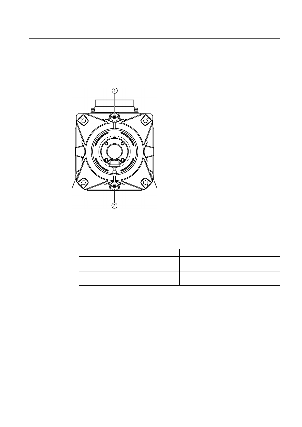
5.4 Connecting the cooling water supply
There are three couplings ① and ② on the bearing shield for the coolant connection. The
lower coupling ② is used to drain the coolant for type of construction IM B3.
Assembly
5.4 Connecting the cooling water supply
Figure 5-5 Standard coolant connections and coolant drain hole
1. With the "Piping" option, piping is attached on the right, left or top at the NDE. You can then
connect the coolant supply radially to the appropriate side.
Different threads are available depending on the machine type.
Machine type Thread
1LH….-3A…-…. / 1MH….-3A…-….
1LH….-3B…-…. / 1MH….-3B…-….
1LH….-4A…-…. / 1MH….-4A…-….
1LH….-4B…-…. / 1MH….-4B…-….
G1/2"
G3/4"
2. Only use valves, fittings and cooling water pipes made of rust-proof, stainless steel in the
cooling system.
3. Make sure that the cooling water complies with the required cooling water specification.
4. Make sure that the appropriate volume of cooling water is available.
SIMOTICS FD 1MH1
Operating Instructions 08/2017 77
Page 78

Assembly
5.4 Connecting the cooling water supply
5. Hold the hexagon coupler with an open-ended wrench while you screw in the water pipes.
NOTICE
Damage to the pipe system
The hexagonal couplers are connected directly to the water pipes inside the machine.
Applying excessive torque when screwing in can damage the pipe system.
● Hold the couplers with an open-ended wrench while you screw in the water pipes.
● Avoid axial forces at the coolant connections.
6. Screw the cooling water pipes into the female thread. You can connect the inlet and outlet
as required.
See also
Coolant specification (Page 36)
Coolant specification (M85 "stainless steel version" option) (Page 38)
NOTICE
Bleed air from the cooling ducts
Adequate machine cooling cannot be guaranteed if the cooling ducts are not completely filled
with water. The machine can overheat.
● Vent the cooling ducts when filling. Completely fill the cooling ducts with water.
SIMOTICS FD 1MH1
78 Operating Instructions 08/2017
Page 79

Electrical connection
Observe the following when carrying out any work on the machine:
● Comply with the general safety instructions
● Comply with the applicable national and sector-specific regulations at the place of
installation
● When using the machine within the European Union, comply with the specifications laid
down in EN 50110‑1 regarding safe operation of electrical equipment.
See also
Safety information (Page 15)
Note
Service Center
If you require support when electrically connecting up the machine, please contact the Service
Center (Page 177).
6
6.1 Safety instructions relating to the electrical connection
WARNING
Connected parts can loosen
If you use fixing elements made from the wrong material or apply the wrong tightening torque,
this could impair current transfer or cause connecting parts to become loose. Fastening
elements can work loosely, so that the minimum air clearances are no longer maintained.
Sparking formation may occur, in an explosive atmosphere it can lead to an explosion. This
could result in death, serious injury or material damage to the machine or even in failure,
which could in turn lead indirectly to material failure of the system.
● Tighten the screwed connections to the specified tightening torques.
● Observe any specifications regarding the materials from which fixing elements must be
made.
● When performing servicing, check the fastenings.
See also
Tightening torques for screw and bolt connections (Page 179)
SIMOTICS FD 1MH1
Operating Instructions 08/2017 79
Page 80
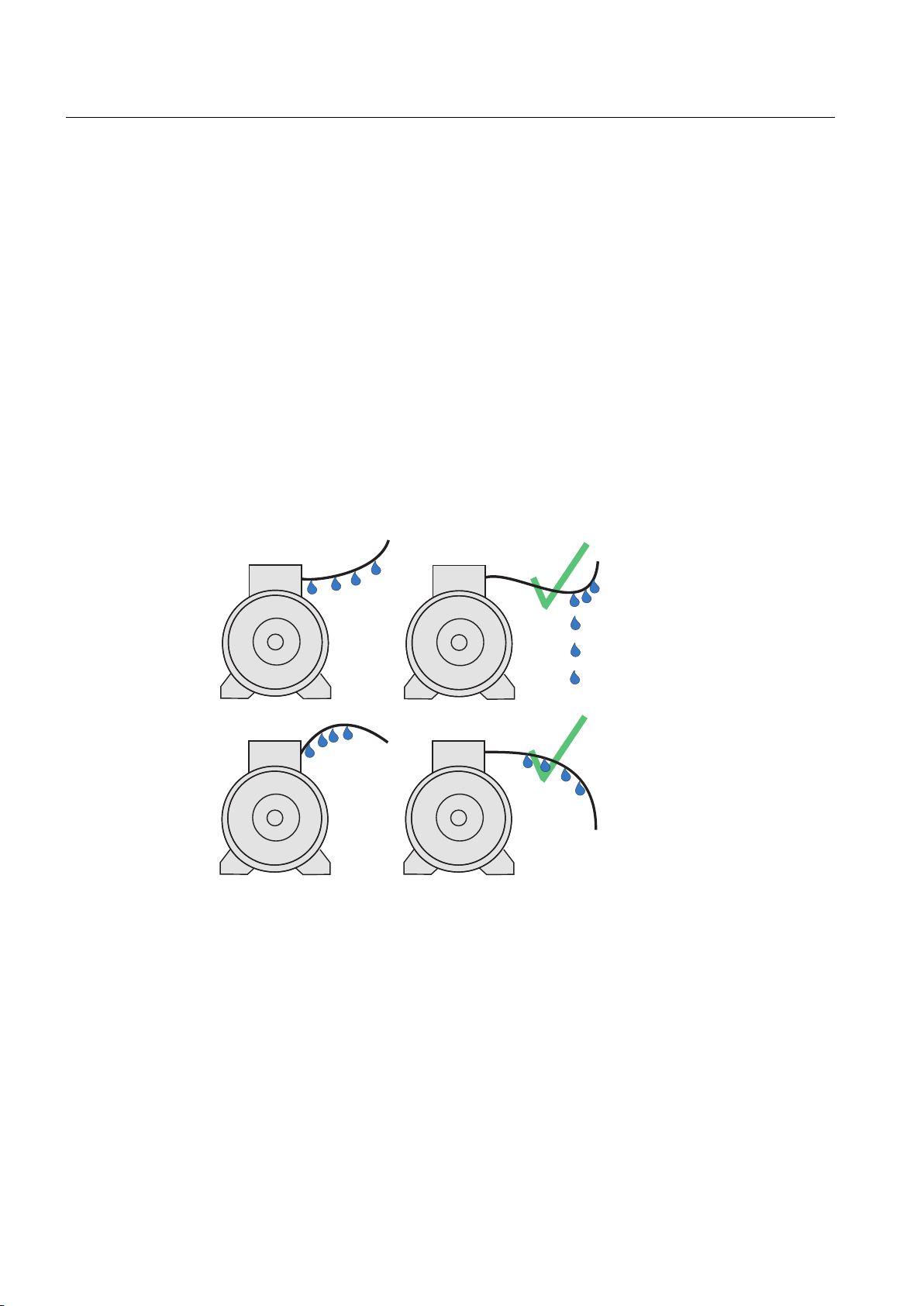
;
;
Electrical connection
6.2 Basic rules
6.2 Basic rules
The following generally applies to electrical connections:
● Ensure that there is a safe and reliable PE ground connection before starting any work.
● The connecting cables can be sealed and secured at every cable entry point into the
terminal box.
● Lay the connecting cables and in particular the PE conductor in the terminal box in an open
arrangement so that chafing of the cable insulation is prevented.
● Connect the machine in such a way that a permanent, safe electrical connection is
maintained. Avoid protruding wire ends.
● Lay and secure external auxiliary cables separately from the main cable. Elements with
cable ties may be present for this purpose.
● In case of high humidity or when installed outside, water drops can move along the cable
jacket and enter the motor through the cable entry and cable gland.
If you route the cable with an appropriate loop then water doesn't enter the terminal box,
but simply drips off.
Figure 6-1 Water drip loop
6.3 Terminal box
Depending on the version, different terminal boxes may be installed on the machine.
Depending on the terminal box, different cable entries and options for the cable connection
are possible. You can identify the terminal box installed on the machine via the illustrations in
the following chapters.
Terminal box 1XB1621 (Page 81)
SIMOTICS FD 1MH1
80 Operating Instructions 08/2017
Page 81
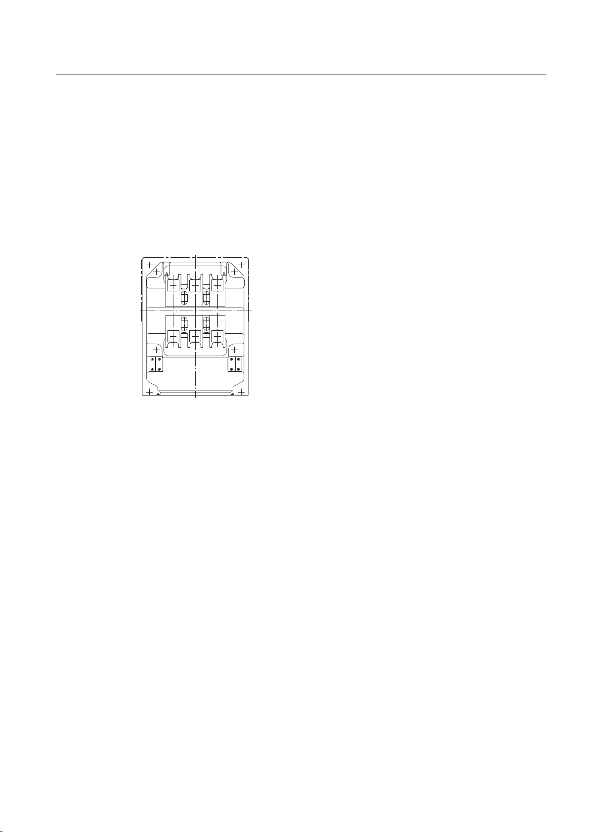
Terminal box 1XB1631 (Page 82)
Terminal box 1XB7730 (Page 83)
Terminal box 1XB7731 (Page 83)
Terminal box 1XB7740 (Page 84)
Terminal box 1XB7750 (Page 85)
6.3.1 Terminal box 1XB1621
Electrical connection
6.3 Terminal box
See also
Figure 6-2 Terminal box 1XB1621
The connecting cables are introduced into the 1XB1621 terminal box through the cable glands
with threaded holes 2 x M80 x 2 and 2 x M25 x 1.5. The cable glands are not included in the
standard scope of supply. The version with sealing insert with break-off ring is optional.
You can find additional information here:
● Bringing cables into the terminal box 1XB... with cable gland (Page 93)
● Connecting cables without cable lugs (Page 96)
● Connecting cables with cable lugs (Page 95)
Bringing cables into the terminal box 1XB... with sealing insert with break-off ring (Page 92)
SIMOTICS FD 1MH1
Operating Instructions 08/2017 81
Page 82
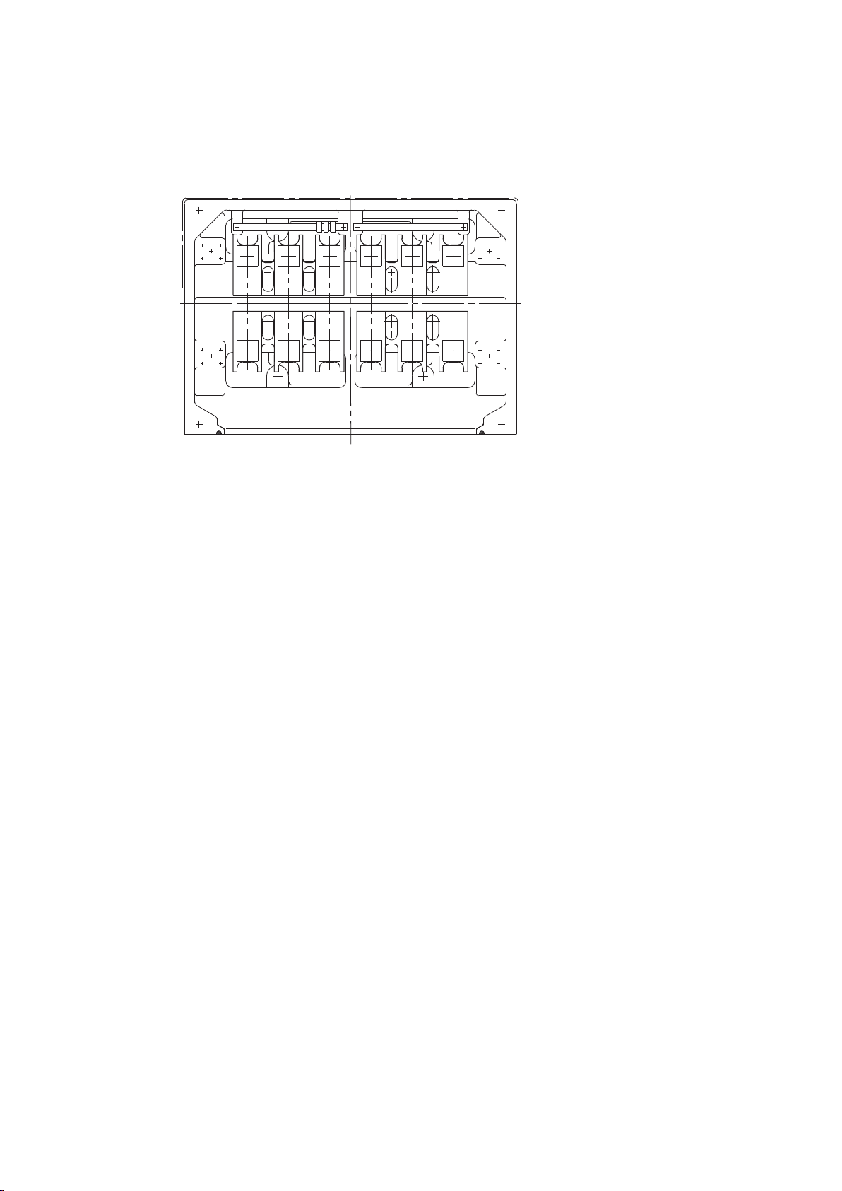
Electrical connection
6.3 Terminal box
6.3.2 Terminal box 1XB1631
Figure 6-3 Terminal box 1XB1631
The connecting cables are introduced into the 1XB1631 terminal box through cable glands
with threaded holes 4 x M80 x 2 and 2 x M25 x 1.5. The cable glands are not included in the
standard scope of supply. The version with onion sealing ring is optional.
See also
You can find additional information here:
● Bringing cables into the terminal box 1XB... with cable gland (Page 93)
● Connecting cables without cable lugs (Page 96)
● Connecting cables with cable lugs (Page 95)
Bringing cables into the terminal box 1XB... with sealing insert with break-off ring (Page 92)
SIMOTICS FD 1MH1
82 Operating Instructions 08/2017
Page 83
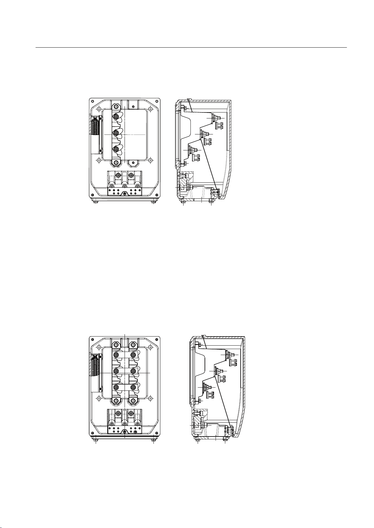
6.3.3 Terminal box 1XB7730
Only a three-core power cable can be connected in terminal box 1XB7730.
Figure 6-4 Terminal box 1XB7730
Electrical connection
6.3 Terminal box
The connecting cables are introduced into the 1XB7730 terminal box through the cable glands
with threaded holes 1 x M72 x 2 and 3 x M25 x 1.5. The cable glands are not included in the
standard scope of supply.
You can find additional information here:
● Bringing cables into the terminal box 1XB... with cable gland (Page 93)
● Connecting cables with cable lugs (Page 95)
● Connecting cables without cable lugs (Page 96)
6.3.4 Terminal box 1XB7731
Figure 6-5 Terminal box 1XB7731
SIMOTICS FD 1MH1
Operating Instructions 08/2017 83
Page 84
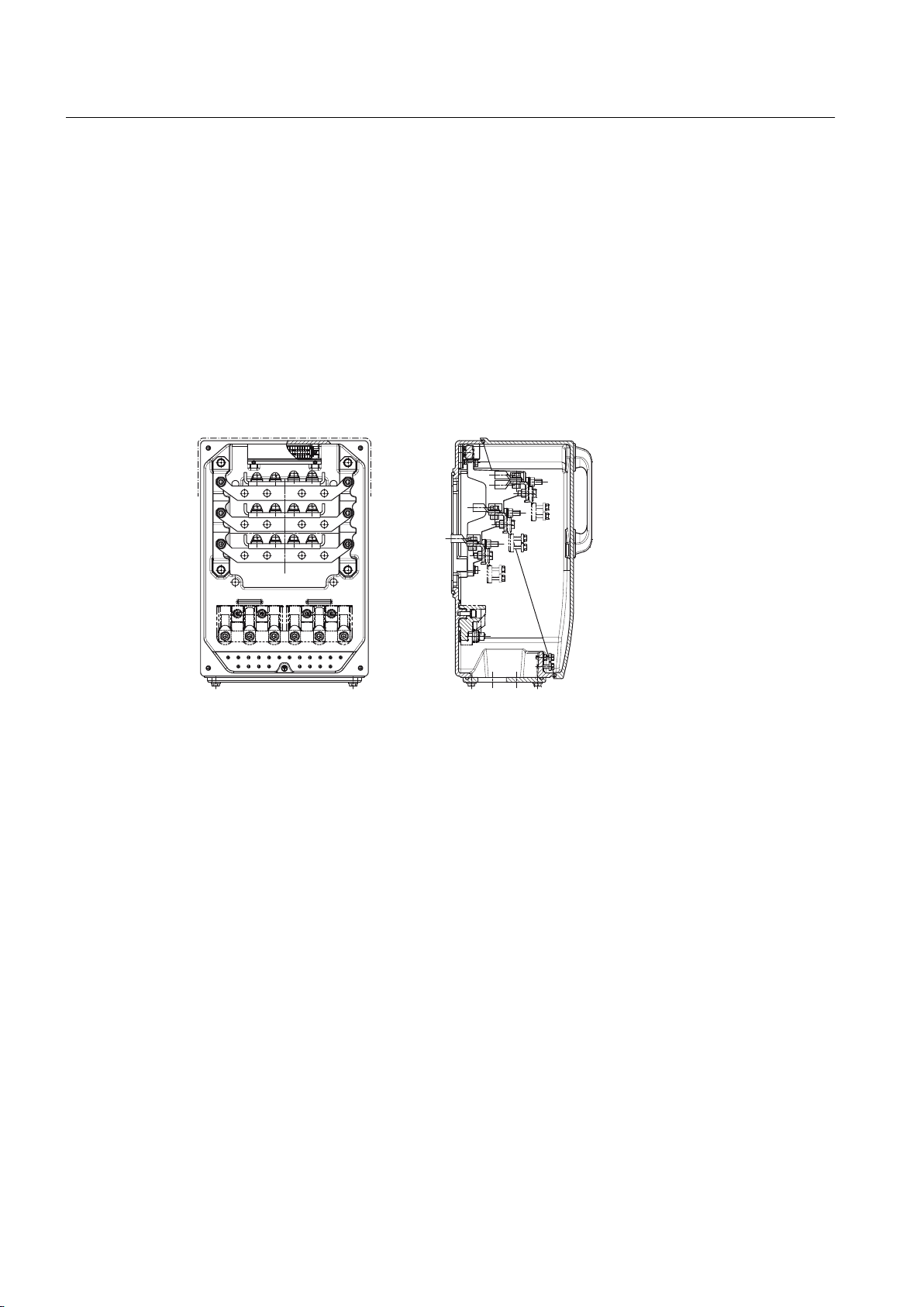
Electrical connection
6.3 Terminal box
The connecting cables are introduced into the 1XB7731 terminal box through the cable glands
with threaded holes 2 x M72 x 2 and 3 x M25 x 1.5. The cable glands are not included in the
standard scope of supply.
You can find additional information here:
● Bringing cables into the terminal box 1XB... with cable gland (Page 93)
● Connecting cables with cable lugs (Page 95)
● Connecting cables without cable lugs (Page 96)
6.3.5 Terminal box 1XB7740
Figure 6-6 Terminal box 1XB7740
The connecting cables are introduced into the 1XB7740 terminal box through the cable glands
with threaded holes 4 x M80 x 2 and 3 x M25 x 1.5. The cable glands are not included in the
standard scope of supply.
You can find additional information here:
● Bringing cables into the terminal box 1XB... with cable gland (Page 93)
● Connecting cables with cable lugs (Page 95)
● Connecting cables without cable lugs (Page 96)
SIMOTICS FD 1MH1
84 Operating Instructions 08/2017
Page 85
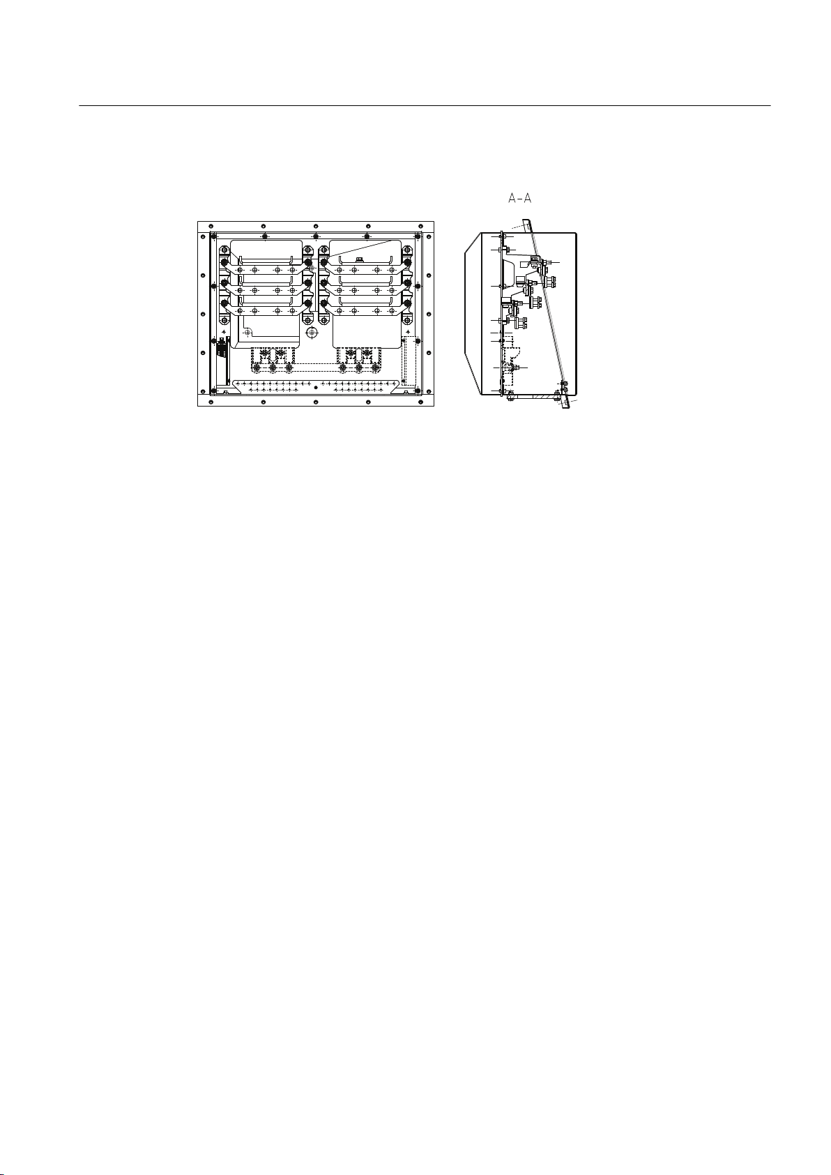
6.3.6 Terminal box 1XB7750
Figure 6-7 Terminal box 1XB7750
The connecting cables are introduced into the 1XB7750 terminal box through the cable glands
with threaded holes 8 x M72 x 2 and 3 x M25 x 1.5. The cable glands are not included in the
standard scope of supply.
Electrical connection
6.3 Terminal box
You can find additional information here:
● Bringing cables into the terminal box 1XB... with cable gland (Page 93)
● Connecting cables with cable lugs (Page 95)
● Connecting cables without cable lugs (Page 96)
6.3.7 Rotating the terminal box
Depending on the terminal box and version, you can rotate the terminal box through ±90° in
accordance with the connection direction. The implementation on the other motor side is
possible only with the support of the Service Center (Page 177). If you want to rotate a terminal
box not listed below, then also contact the Service Center.
Rotating the terminal box depends on the mount and the cross-section of the internal stator
cables as well as the terminal box type:
● 1XB7730
– With installed internal stator cables, you can rotate the terminal box through ±90°.
● 1XB7731
– For six or fewer cables, you can rotate the terminal box with installed stator cables
through ±90°.
– For more than six cables, you must remove the internal stator cables before rotation.
SIMOTICS FD 1MH1
Operating Instructions 08/2017 85
Page 86

Electrical connection
6.3 Terminal box
● 1XB7740
– For 12 or fewer cables and lower cross-sections, you can rotate the terminal box with
installed stator cables through ±90°.
– For more than 12 cables - or for cables with a cross-section greater than 50 mm² - you
must remove the internal stator cables before rotating the terminal box.
● 1XB7750
– Remove the internal stator cables before rotating the terminal box.
Rotating a terminal box with mounted stator cables
1. Ensure that the motor is disconnected from the power supply.
2. Release two diagonally opposed screws for the cover, and secure the cover using two M10
threaded bars screwed in diagonally opposing one another. Release the two other screws
and lift the cover off the terminal box. The terminal box cover is very heavy. Especially when
in a lateral position, ensure that the terminal box does not fall down.
3. If the motor is already connected:
– Remove the cables of the power supply.
– Release the screw connection of the cable entry. Remove the cables through the
opening.
4. Remove the grounding straps on two sides of the terminal box lower section.
5. Remove the screwed joints of the lower section with the console or optionally the cable
duct.
6. Screw in two eye-bolts diagonally in the M10 thread at the corners. Slightly raise the terminal
box housing using a crane.
7. Rotate the terminal box through ±90° in the desired direction. Carefully place the terminal
box down. Take care not to damage the seal.
8. Screw the terminal box with the console / cable duct (4 x M16, tightening torque 170 Nm).
9. Fasten the grounding straps to the terminal box lower section and the console or cable duct:
– After rotation, remove the plugs of the two nearest M8 threads on the console or cable
duct.
– Grind the surface at the drilled holes so that the grounding straps have metallic contact.
– Then fasten the two straps to the terminal box lower section and the console or cable
duct (4x M8, tightening torque 11 Nm).
– Protect the bare areas at the contact with corrosion protection.
10.Reconnect the power supply cables. More information:
– Connecting the grounding conductor (Page 89)
– Introducing and routing the cables ...
– Connecting cables ...
11.Screw in the two diagonally arranged threaded bars and slide the cover onto these bars.
Take care not to damage the seal.
SIMOTICS FD 1MH1
86 Operating Instructions 08/2017
Page 87

12.Fix the two free screw connections and tighten by hand.
13.Remove the threaded bars and screw in the two other screws.
14.Tighten all screws (4 x M10, tightening torque 40 Nm).
Rotating a terminal box with removed stator cables
1. Ensure that the motor is disconnected from the power supply.
2. Release two diagonally opposed screws for the cover, and secure the cover using two M10
threaded bars screwed in diagonally opposing one another. Release the two other screws
and lift the cover off the terminal box. The terminal box cover is very heavy. Especially when
in a lateral position, ensure that the terminal box does not fall down.
3. If the motor is already connected:
– Remove the cables of the power supply.
– Release the screw connection of the cable entry. Remove the cables through the
opening.
4. Release the screwed connections of the internal stator cables, optionally also those at the
neutral point.
Electrical connection
6.3 Terminal box
5. Remove the grounding straps on two sides of the terminal box lower section.
6. Remove the screwed joints of the lower section with the console or optionally the cable
duct.
7. Screw in two eye-bolts diagonally in the M10 thread at the corners. Slightly raise the terminal
box housing using a crane.
8. Rotate the terminal box through ±90° in the desired direction. Carefully place the terminal
box down. Take care not to damage the seal.
9. Screw the terminal box with the console / cable duct (4 x M16, tightening torque 170 Nm).
10.Fasten the grounding straps to the terminal box lower section and the console or cable duct:
– After rotation, remove the plugs of the two nearest M8 threads on the console or cable
duct.
– Grind the surface at the drilled holes so that the grounding straps have metallic contact.
– Then fasten the two straps to the terminal box lower section and the console or cable
duct (4x M8, tightening torque 11 Nm).
– Protect the bare areas at the contact with corrosion protection.
11.Connect the cables in accordance with the circuit diagram on the inside of the cover (M12,
tightening torque 20 Nm). Ensure that the minimum air clearances are observed. More
information:
Minimum air clearances (Page 100)
12.Reconnect the power supply cables. More information:
– Connecting the grounding conductor (Page 89)
– Introducing and routing the cables ...
– Connecting cables ...
SIMOTICS FD 1MH1
Operating Instructions 08/2017 87
Page 88

Electrical connection
6.3 Terminal box
13.Screw in the two diagonally arranged threaded bars and slide the cover onto these bars.
Take care not to damage the seal.
14.Fix the two free screw connections and tighten by hand.
15.Remove the threaded bars and screw in the two other screws.
16.Tighten all screws (4 x M10, tightening torque 40 Nm).
See also
Connecting cables with cable lugs (Page 95)
Connecting cables without cable lugs (Page 96)
Bringing cables into the terminal box 1XB... with cable gland (Page 93)
6.3.8 Mounting/removing the terminal box
When removing or installing the terminal box cover, secure it using diagonally arranged M10
threaded bars to prevent it falling.
Removing the terminal box
1. Release two diagonally opposing screws at the terminal box cover and replace them by
threaded bars.
2. Release the two other screws.
3. Carefully pull the terminal box cover over the threaded bars.
Mounting the terminal box
1. Screw in the two threaded bars diagonally at the lower section of the terminal box.
2. Slide the terminal box cover over the threaded bars onto the lower section of the terminal
box.
3. Screw the screws into the free holes and tighten by hand.
4. Release the threaded bars.
5. Tighten all four M10 screws, tightening torque 40 Nm.
SIMOTICS FD 1MH1
88 Operating Instructions 08/2017
Page 89
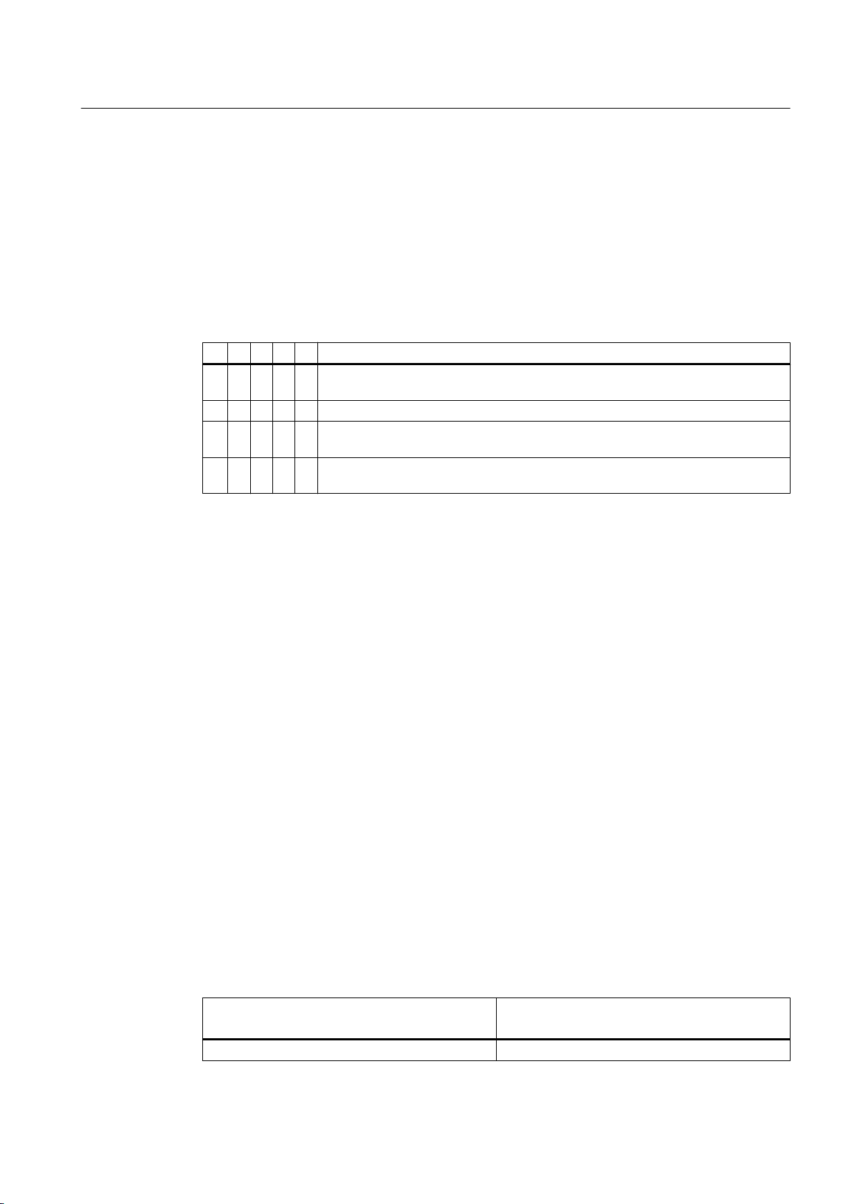
6.4 Preparation
6.4.1 Terminal designation
According to IEC / EN 60034‑8, the following basic definitions apply to the terminal
designations for 3-phase machines:
Table 6-1 Terminal designations using the 1U1-1 as an example
1 U 1 - 1 Designation
x Index for pole assignment for pole-changing machines where applicable. A lower
index signifies a lower speed. Special case for split winding.
x Phase designation U, V, W
x Index for winding start (1) or end (2) or if there is more than one connection per
winding
x Additional indices for cases in which it is obligatory to connect parallel power feed
cables to several terminals with otherwise identical designations
Electrical connection
6.4 Preparation
6.4.2 Selecting cables
Take the following criteria into account when selecting the connecting cables:
● Rated current
● Rated voltage
● Possibly a service factor
● System-dependent conditions, such as ambient temperature, routing type, cable crosssection as defined by required length of cable, etc.
● Requirements according to IEC/EN 60204‑1
● Dimensioning for bundled cable routing, e.g. according to DIN VDE 0298 Part 4 or
IEC 60364-5-52
● Requirements according to IEC/EN 60079-14
● Configuration notes
6.4.3 Connecting the grounding conductor
The grounding conductor cross-section of the machine must be in full conformance with the
installation specifications, e.g. in accordance with EN 60204‑1.
Table 6-2 Determining the cross-section of the grounding conductor
Phase conductor cross-section S
[mm²]
S > 35 S/2
SIMOTICS FD 1MH1
Operating Instructions 08/2017 89
Cross-section of grounding conductor
[mm²]
Page 90
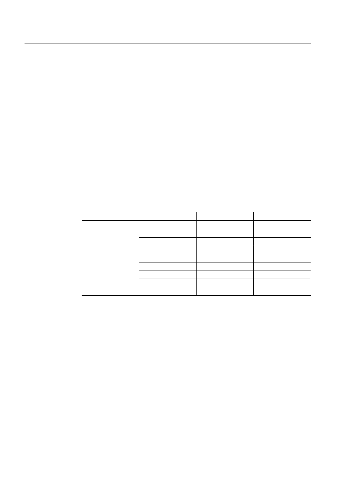
Electrical connection
6.4 Preparation
There is a hexagon bolt with a flat washer and a spring washer on the stator frame at the
designated connecting point for the grounding conductor. The grounding conductor can be
connected as follows:
● With stranded cables with cable lugs
● With flat cables with cable end designed accordingly
As an alternative, you can connect the grounding conductor without cable lugs using a terminal
plate at the marked connection point.
Connecting the grounding conductor
● Ensure that the connecting surface is bare and is protected against corrosion using a
suitable substance, e.g. acid-free vaseline.
● Arrange the flat washer and spring washer under the bolt head.
● Check that the maximum permissible clamping thickness of 10 mm for the cable lug or strap
is not exceeded.
● Fasten the clamping screw according to the following table. Screw-in depth and tightening
torque are different depending on whether cable lugs or ground terminals are used.
Screw Screw-in depth Tightening torque
When using cable lugs M6 > 6 mm 8 Nm
M8 > 8 mm 20 Nm
M12 x 25 > 16 mm 38 Nm
M16 x 35 > 20 mm 92 Nm
When using grounding
terminals
M6 > 9 mm 8 Nm
M8 > 12 mm 20 Nm
M10 > 15 mm 40 Nm
M12 > 18 mm 70 Nm
M16 > 20 mm 170 Nm
● Use the connecting terminals designated for the grounding conductor in the terminal box.
See also
Converter operation (Page 106)
6.4.4 Connect metal shield in the terminal box
If you are using metal-armored cables that are inserted into the terminal or auxiliary terminal
boxes with non-intrinsically safe circuits, then ground the metal shield in the terminal box.
Additional grounding points are permissible.
● In terminal boxes with internal grounding part, connect the metal shield to the internal
grounding point.
● In terminal boxes without internal grounding part, connect the metal shield to one of the
green-yellow grounding terminals.
SIMOTICS FD 1MH1
90 Operating Instructions 08/2017
Page 91

6.4.5 Connection without terminal box
If the machine was ordered without terminal box (where the cables are simply brought out of
the motor), then the proper connection must be made in an external terminal box.
WARNING
Incorrect dimensioning
Faults can occur if the appropriate technical data is not complied with when connecting up.
For instance, degree of protection, minimum air and creepage distances. These faults can
result in eventual or immediate death, serious injury or material damage.
● Ensure that the external terminal box is dimensioned according to the data on the rating
plate and is suitable for the respective use.
If the motor has been ordered with brought-out leads, in this case you must comply with the
relevant conditions for Zone 2. It is assumed that the buyer, the installer and users of the
installation are familiar with these conditions and will carefully observe them.
Electrical connection
6.4 Preparation
6.4.6 Connecting the machine for a specific direction of rotation
If the machine has one shaft extension or two shaft extensions with different diameters, the
direction of rotation when looking at the front of the single or the thicker shaft extension is
defined as follows:
● If you connect the power cables in the phase sequence L1, L2, L3 to U, V, W, the resulting
rotation will be clockwise.
● If you interchange two connections, e.g. L1, L2, L3 to W, V, U, the resulting rotation will be
counter-clockwise.
● On machines which are only allowed to run in one direction, the rating plate shows an arrow
which indicates the permitted direction of rotation, and it also specifies the terminal
connections in the required phase sequence.
NOTICE
Incorrect direction of rotation
The machine will not be adequately cooled if it is operated other than how it was originally
ordered or with the incorrect direction of rotation. This can result in machine damage.
Observe the direction of rotation data on the nameplate.
SIMOTICS FD 1MH1
Operating Instructions 08/2017 91
Page 92
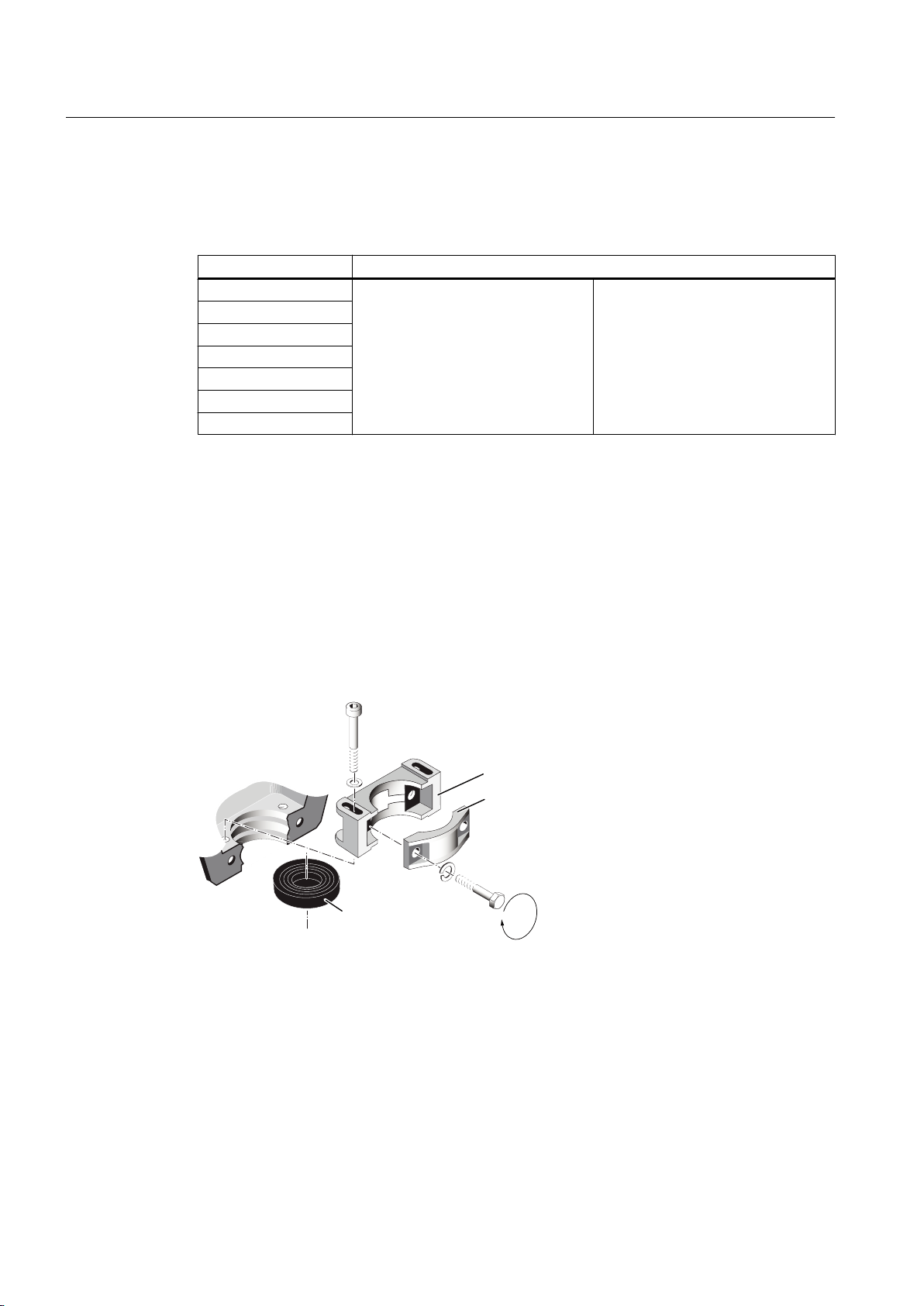
1P
ཱ
ི
Electrical connection
6.5 Inserting and routing the cables
6.5 Inserting and routing the cables
Table 6-3 Connection technology (with cable lug / connection without cable lug)
Terminal box Connection
GT640
1XB1621
1XB1631
1XB7730
1XB7731
1XB7740
1XB7750
With cable lug (Page 95)
Without cable lug (Page 96)
6.5.1 Bringing cables into the terminal box 1XB... with sealing insert with break-off ring
The 1XB1621, 1XB1631 terminal boxes can be equipped optionally with a sealing insert with
break-off ring. The connecting cable is sealed at the cable entry location using a cut-out sealing
insert and is fastened using a strain relief device.
Bringing cables into the terminal box and connecting them
The terminal box is opened, the cable cut to the correct length and stripped back. Make sure
that no external forces are acting on the cable connection.
Figure 6-8 Strain relief device and sealing insert
Proceed as follows when connecting the cables:
1. Remove the top part of the strain relief ③ and release the fixing screws for the bottom part
of the strain relief ②. The strain relief device can be located either in the terminal box or
externally. If necessary, switch the direction sense of the strain relief device.
2. Cut the seal insert ① so that its opening is 1 to 3 mm smaller than the diameter of the cable.
3. Pull the sealing insert over the end of the cable.
SIMOTICS FD 1MH1
92 Operating Instructions 08/2017
Page 93
Electrical connection
6.5 Inserting and routing the cables
4. Prepare the end of the cable depending on the cable and its use, e.g. with a cable lug.
5. Connect the ends of the cables to the terminals in accordance with the circuit diagram.
The circuit diagram is located in the cover of the terminal box.
Refer to the "Connecting cables..." section for more information.
6. You might need to use a sleeve made of suitable sealing tape to modify the diameter where
it passes through the sealing insert. Push the sealing insert onto the prepared sleeve.
7. Insert the cable with the seal insert in position into the gland opening. Screw the strain relief
device together once the cable is in a concentric position in the gland opening.
8. Secure the strain relief device.
9. Tighten the clamping screws of the strain relief device so that the cable is clamped as
necessary, but do not damage the cable insulation. We recommend a torque of 5 Nm.
10.Retighten the clamping screws after 24 hours.
WARNING
Damage to insulation
If you tighten the strain relief clip clamping screws too tightly this can damage the
insulation. Damaged insulation can result in arcing. This can result in death, serious injury
or material damage.
Tighten the strain relief clip clamping screws to the specified torque.
6.5.2 Bringing cables into the terminal box 1XB... with cable gland
The connection cables are inserted into the terminal box via an exchangeable cable entry plate
or cable entry support. The cable entry plate is drilled by default. The cable glands are not
included in the standard scope of supply.
You can rotate the cable entry through 180°.
Table 6-4 Cable entry plate versions
Terminal box Standard
Cable entry plate with boreholes
1XB1621 2 x M80 x 2 + 2 x M25 x 1.5
1XB1631 4 x M80 x 2 + 2 x M25 x 1.5
1XB7730 1 x M72 x 2 + 3 x M25 x 1.5
1XB7731 2 x M72 x 2 + 3 x M25 x 1.5
1XB7740 4 x M80 x 2 + 3 x M25 x 1.5
1XB7750 8 x M72 x 2 + 3 x M25 x 1.5
Explosion protected version / op‐
tion L01
Undrilled (Page 93)
SIMOTICS FD 1MH1
Operating Instructions 08/2017 93
Page 94

Electrical connection
6.5 Inserting and routing the cables
Insert the cable into the terminal box
Proceed as follows when introducing cables into the terminal box:
1. Unscrew the cable entry plate.
2. Drill the required number of holes or threads in the required size in the cable entry plate.
Ensure that the cable entry plate can be assembled after drilling and that it features
sufficient stiffness.
3. Fit the required cable glands.
4. Route the cables through the cable glands.
5. Fit the cable entry plate to the terminal box with the assembled cables.
6. Connect the ends of the cables to the terminals in accordance with the circuit diagram. The
circuit diagram is located in the cover of the terminal box.
Refer to Chapter "Connecting cables ..." for more information.
Drill holes in the cable entry plate
If you drill holes in the cable entry plate for explosion-protected motors, then document the
data about these holes in the motor documentation:
● Number and size of the holes
● Type of thread, e.g. metric or NPT
Data regarding the installation of pipes and accessories is provided in IEC / EN 60079-14.
6.5.3 Certified cable entries, thread adapters and sealing plugs
Use only sealing plugs, cable entries & conductor entries and thread adapters that are certified
and marked for use in the respective hazardous zone.
6.5.4 Laying cables
● Lay the cables in accordance with IEC/EN 60364-5-52.
● For fixed cables, use EMC- and Ex-certified cable glands with strain relief. Screw the cable
glands into the threaded holes in the entry plate, which can be unscrewed. The cable glands
are not included in the scope of supply.
Comply with the installation and operation conditions specified in the certificate for these
cable glands and check that they have been fully complied with.
● For loose cables, use twist-protection cable glands with strain relief.
● Use shielded cables whose shields are conductively connected to a large area of the
terminal box of the motor via EMC cable glands.
● Arrange the exposed connecting cables in the terminal box so that the PE conductor has
excess length and the insulation of the cable strands cannot be damaged.
SIMOTICS FD 1MH1
94 Operating Instructions 08/2017
Page 95
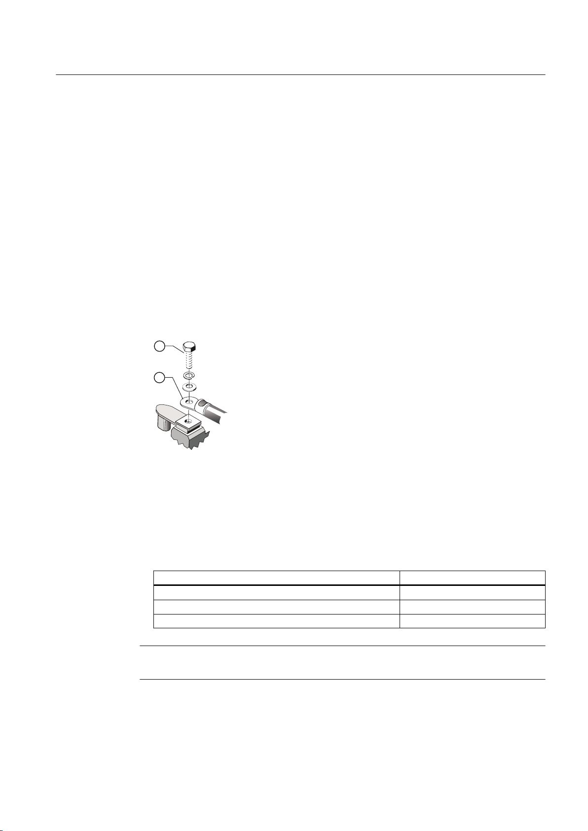
● In the case of aluminum connecting bars, insert a steel washer between the cable lug and
the connecting bar. This prevents contact corrosion.
● Correctly close and seal threads or holes that are not being used ensuring that the IP degree
of protection is maintained. The IP degree of protection is specified on the rating plate.
Replace the cable glands that are not being used by appropriately certified screw plugs.
6.5.5 Connecting cables with cable lugs
1. Select the cable lugs according to the required cable cross-section and fixing screw or stud
size. Information about the maximum cross-section for the respective standard terminal
box design can be found in the catalog.
A sloped/angular arrangement of the supply cables is only permitted provided the required
minimum air clearances are met.
2. Remove the insulation from the conductor ends so that the remaining insulation reaches
almost up to the cable lug ①. Connect only one conductor per cable lug.
3. Fasten the cable lug to the end of the conductor correctly, e.g. by squeezing.
Electrical connection
6.5 Inserting and routing the cables
Figure 6-9 Connection with cable lug and fixing screw (schematic diagram)
4. Insulate the cable lug sleeves where necessary to ensure minimum air clearances and the
creepage distance are maintained.
5. Place the cable lug on the terminal support. If you are using a disconnecting link, check its
positioning.
For terminal boxes 1XB7740 and 1XB7750, place the cable lug on the busbar.
6. Tighten the fixing element ② with the corresponding tightening torque:
Fixing element Tightening torque
Fastening screw M12 20 Nm
Fixing screws M16 40 Nm
Fixing nuts M12 20 Nm
Note
You can find more information in Chapter 2 of catalog D81.8.
SIMOTICS FD 1MH1
Operating Instructions 08/2017 95
Page 96

Electrical connection
6.5 Inserting and routing the cables
WARNING
Explosion hazard if cable lugs without side guards are used
For cable cross-sections under 70 mm2, cable lugs without side guard may twist. The
minimum air clearances may be underrun and cause an explosion.
This can result in death, serious injury, or material damage.
● For cable cross-sections under 70 mm2, use only cable lugs with side guard.
● Make sure that the minimum air clearances (Page 100) are observed.
6.5.6 Connecting cables without cable lugs
Lug terminal connections - which are suitable for connecting flexible and stranded conductors
without the use of wire end ferrules - may be installed if ordered accordingly. If you wish to
use wire end ferrules, then before connecting the cable, attach these so as to form a technically
correct, current-carrying crimped joint at the end of the conductor.
Procedure
NOTICE
Overheating of the conductor ends
If the end of the conductor is not correctly enclosed by the wire end ferrule, but is trapped by
it, this can lead to overheating.
● Insert only one conductor end into each wire end ferrule, and attach the wire end ferrule
correctly.
● Insert only one conductor end into each terminal.
Ensure that the minimum air clearances and the creepage distance are maintained for the
connection.
1. Open the terminal box and cut the cable to the correct length.
The clips of the 1XB7730/1XB7731 terminal boxes can accept cables with maximum
185 mm² cross-section.
2. Prepare the end of the cable depending on the cable and its use. Make sure that no external
forces are acting on the cable connection.
3. Insulate the conductor ends in such a way that the remaining insulation reaches almost up
to the cable lug.
SIMOTICS FD 1MH1
96 Operating Instructions 08/2017
Page 97
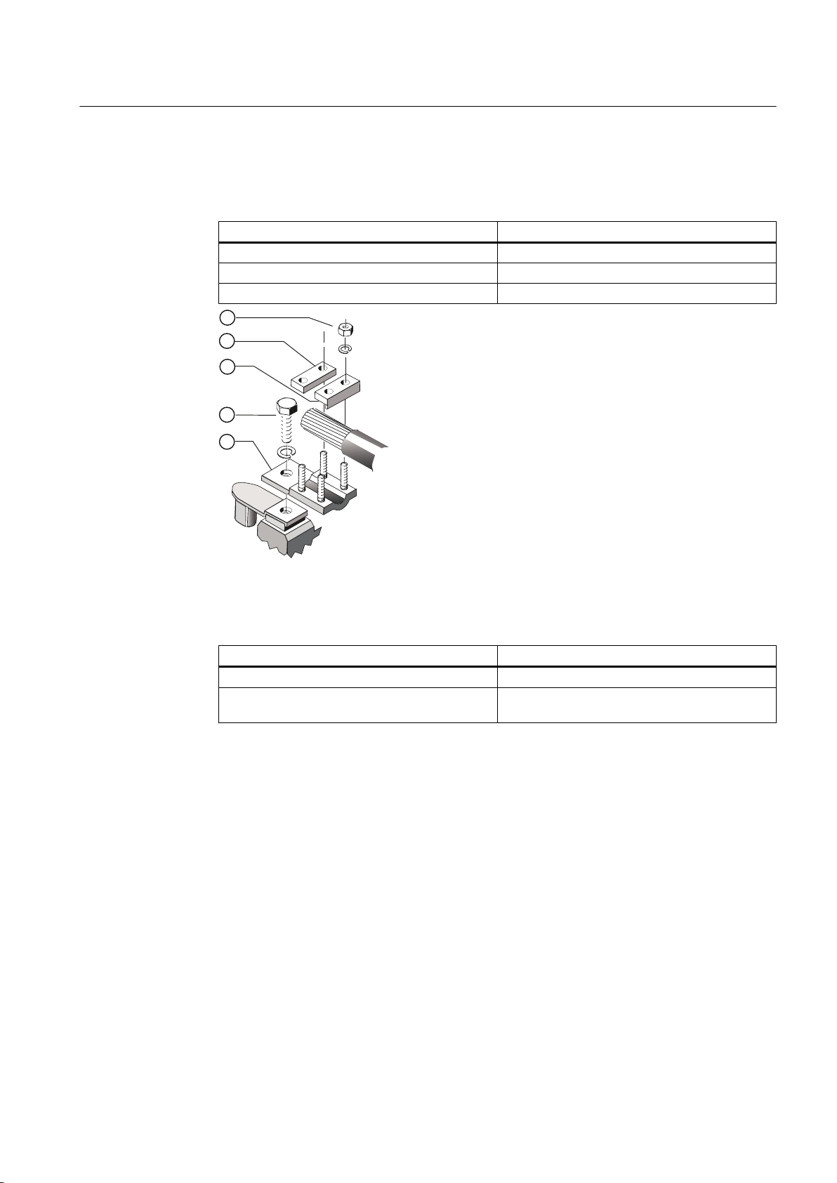
Electrical connection
6.5 Inserting and routing the cables
4. Make sure the terminal clamps ③, ④ are arranged correctly for the size of the conductor.
Insert the cable into the terminal clamps. Tighten the clamping nuts ⑤ to the tightening
torque as specified in the following table.
Terminal box Tightening torque
GT640 / 1XB1621 / 1XB1631 / 1XB1634 8 Nm
1XB7730 / 1XB7731 4 Nm
1XB7740 / 1XB7750 8 Nm
Figure 6-10 Connection using terminal clamps (schematic diagram)
5. If you have loosened the terminal body clamping bolts ②, then retighten them with the
following torque:
Terminal box Tightening torque
1XB1621 / 1XB1631 / 1XB1634 40 Nm
GT640 / 1XB7730 / 1XB7731 /
1XB7740 / 1XB7750
20 Nm
For terminal boxes GT640, 1XB7730 and 1XB7731, the terminal element ① is fastened
using a terminal nut M12 on the threaded stud of the terminal support with a torque of 20 Nm.
Lug terminal connections may be installed if ordered accordingly, which are suitable for
connecting flexible and stranded conductors without the use of wire end ferrules. If you wish
SIMOTICS FD 1MH1
Operating Instructions 08/2017 97
Page 98

Electrical connection
6.5 Inserting and routing the cables
to use wire end ferrules, then before connecting the cable, attach these so as to form an
appropriate, current-carrying crimped joint at the end of the conductor.
WARNING
Danger of explosion if the conductor ends become too hot
If the end of the conductor is not correctly enclosed by the wire end ferrule, but is trapped by
it, this can lead to overheating. The temperature class of the machine can be exceeded. This
can trigger ignition of an explosive mixture. This can result in death, serious injury or material
damage.
● Insert only one conductor end into each wire end ferrule. Attach the wire end ferrule
correctly.
● Insert only one conductor end into each terminal.
6.5.7 Use of aluminum conductors
If you are using aluminum conductors, then comply with the following:
● Use only cable lugs that are suitable for connecting aluminum conductors.
● Immediately before inserting the aluminum conductor, remove the oxide layer from the
contact areas on the conductor and/or the mating piece. Do this using a brush or file.
● Then grease the contact areas immediately using neutral Vaseline. This prevents a new
oxide layer from forming.
NOTICE
Aluminum flow due to contact pressure
Aluminum flows following installation due to the contact pressure. The connection using
clamping nuts can loosen as a result. The contact resistance increases, obstructing the
current from being conducted. This can result in fire and material damage to the machine
– or even in total failure, as well as material damage to the plant or system due to machine
failure.
● Retighten the clamping nuts after approximately 24 hours and then again after
approximately four weeks. Make sure that the terminals are de-energized before you
tighten the nuts.
For terminal box &1XB7.. with aluminum connection bars, you can also connect copper cables
using copper cable lugs.
SIMOTICS FD 1MH1
98 Operating Instructions 08/2017
Page 99

6.5.8 Using single-stranded cables
WARNING
High temperatures from induced eddy currents
With high currents and where several single-stranded cables are used instead of multiplestranded cables, high temperatures can result in the cable entry area due to induced eddy
currents. A short-circuit and an explosion may occur. This can result in death, serious injury,
or material damage.
● After commissioning, ensure that the temperature limits of the connected power cables
are not exceeded during operation. This temperature effect can be reduced by altering
the conditions at the entry points or by using modified cable entry plates after consultation
with the manufacturing plant.
● Use a cable entry plate made of non-ferrous metal.
6.5.9 Internal equipotential bonding
Electrical connection
6.5 Inserting and routing the cables
Between the ground terminal in the terminal box enclosure and the machine enclosure, the
fixing screws of the terminal box serve as PE conductor connection.
Between terminal box cover and terminal box enclosure, the cover fixing screws serve as
equipotential bonding.
A special external ground conductor is only installed if, for example, flat seals are mounted
without additional support.
When performing any installation work, you must always take care to ensure that all
equipotential bonding measures remain effective.
6.5.10 Stepless mating face for the seal in the terminal box cover
The sealing face of the terminal box cover is formed by the terminal box enclosure and the
cable entry element. Therefore make sure these parts are correctly aligned, so as to ensure
the seal and hence the degree of protection.
Align the cable entry support and the cable entry plate to the terminal box enclosure so that
the sealing surface between the terminal box and the terminal box cover form a flat face. There
must be no steps in the sealing area.
SIMOTICS FD 1MH1
Operating Instructions 08/2017 99
Page 100
Electrical connection
6.5 Inserting and routing the cables
6.5.11 Minimum air clearances
After proper installation, verify that the minimum air clearances between non-insulated parts
are maintained. Be aware of any protruding wire ends.
Table 6-5 Minimum air clearance dependent on rms value of the alternating voltage U
Rms value of the alternating voltage V
≤ 500 V 8 mm
≤ 630 V 10 mm
≤ 800 V 12 mm
≤ 1000 V 14 mm
≤ 1250 V 18 mm
Values apply at an installation altitude of up to 2000 m.
When determining the required minimum air clearance, the voltage value in the table may be increased
by a factor of 1.1, so that the rated input voltage range is taken into account during general use.
6.5.12 Finishing connection work
1. Before closing the terminal box, please check that:
– The electrical connections in the terminal box have been made in accordance with the
specifications above and tightened with the correct tightening torque.
– The machine is connected in such a way that it rotates in the direction specified.
– The inside of the terminal box is clean and free of any cable debris, dirt and foreign
bodies.
Minimum air clearance
rms
rms
See also
– All of the seals and sealing surfaces of the terminal box are intact and in a good condition.
– Any unused cable entries are sealed with glued-in ferrous or certified sealing elements.
The sealing elements can only be removed with a tool.
– The connecting cables are laid in an open arrangement, so that the cable insulation
cannot be damaged during operation.
2. Close the terminal box with the cover fixing screws, see chapter Tightening torques for
screw and bolt connections (Page 179).
Mounting/removing the terminal box (Page 88)
SIMOTICS FD 1MH1
100 Operating Instructions 08/2017
 Loading...