

Siemens SIMOTICS DP 1PC134, SIMOTICS DP 1PC136 Operating Instructions Manual

Operating Instructions
02/2019Edition
1PC134 / 1PC136 SH 132 ... 315
SIMOTICS DP
Crane motors
Low-voltage motors
www.siemens.com


Low-voltage motors
SIMOTICS DP
1PC134, 1PC136 crane motors SH
132 ... 315
Introduction
1
Operating Instructions
Safety instructions
Description
Preparing for use
Assembly
Electrical connection
Commissioning
Operation
2
3
4
5
6
7
8
Maintenance
Spare parts
Disposal
Service and support
Technical data
Quality documents
9
10
11
A
B
C
02/2019
A5E43212221A

Legal information
Warning notice system
This manual contains notices you have to observe in order to ensure your personal safety, as well as to prevent
damage to property. The notices referring to your personal safety are highlighted in the manual by a safety alert
symbol, notices referring only to property damage have no safety alert symbol. These notices shown below are
graded according to the degree of danger.
DANGER
indicates that death or severe personal injury will result if proper precautions are not taken.
WARNING
indicates that death or severe personal injury may result if proper precautions are not taken.
CAUTION
indicates that minor personal injury can result if proper precautions are not taken.
NOTICE
indicates that property damage can result if proper precautions are not taken.
If more than one degree of danger is present, the warning notice representing the highest degree of danger will be
used. A notice warning of injury to persons with a safety alert symbol may also include a warning relating to property
damage.
Qualified Personnel
The product/system described in this documentation may be operated only by personnel qualified for the specific
task in accordance with the relevant documentation, in particular its warning notices and safety instructions. Qualified
personnel are those who, based on their training and experience, are capable of identifying risks and avoiding
potential hazards when working with these products/systems.
Proper use of Siemens products
Note the following:
WARNING
Siemens products may only be used for the applications described in the catalog and in the relevant technical
documentation. If products and components from other manufacturers are used, these must be recommended or
approved by Siemens. Proper transport, storage, installation, assembly, commissioning, operation and
maintenance are required to ensure that the products operate safely and without any problems. The permissible
ambient conditions must be complied with. The information in the relevant documentation must be observed.
Trademarks
All names identified by ® are registered trademarks of Siemens AG. The remaining trademarks in this publication
may be trademarks whose use by third parties for their own purposes could violate the rights of the owner.
Disclaimer of Liability
We have reviewed the contents of this publication to ensure consistency with the hardware and software described.
Since variance cannot be precluded entirely, we cannot guarantee full consistency. However, the information in this
publication is reviewed regularly and any necessary corrections are included in subsequent editions.
Siemens AG
Division Process Industries and Drives
Postfach 48 48
90026 NÜRNBERG
GERMANY
Document order number: A5E43212221A
Ⓟ 02/2019 Subject to change
Copyright © Siemens AG 2017 - 2019.
All rights reserved

Table of contents
1 Introduction...................................................................................................................................................9
1.1 About these instructions...........................................................................................................9
1.2 Compiling personal documents................................................................................................9
2 Safety instructions ......................................................................................................................................11
2.1 Information for the nominated person in control of the electrical installation .........................11
2.2 The 5 safety rules...................................................................................................................11
2.3 Qualified personnel ................................................................................................................12
2.4 Safe handling .........................................................................................................................12
2.5 Electromagnetic fields when operating electrical power engineering installations.................14
2.6 Electrostatic sensitive devices ...............................................................................................14
2.7 Processes that generate high levels of electrostatic charge ..................................................15
2.8 Electromagnetic compatibility.................................................................................................16
2.9 Interference immunity.............................................................................................................16
2.10 Interference voltages when operating the converter ..............................................................16
2.11 Special designs and construction versions ............................................................................16
3 Description..................................................................................................................................................17
3.1 Area of application .................................................................................................................17
3.1.1 CE marking ............................................................................................................................17
3.1.2 IE2 marking ............................................................................................................................18
3.1.3 Operating UL-certified machines with a converter .................................................................18
3.2 Rating plates ..........................................................................................................................18
3.3 Installation ..............................................................................................................................20
3.3.1 Machine design ......................................................................................................................20
3.3.2 Cooling and ventilation...........................................................................................................20
3.3.2.1 Motors with a fan....................................................................................................................21
3.3.2.2 Machines without a fan ..........................................................................................................22
3.3.3 Bearings .................................................................................................................................22
3.3.4 Balancing ...............................................................................................................................23
3.3.5 Types of construction/method of installation ..........................................................................23
3.3.6 Degree of protection...............................................................................................................24
3.3.7 Environmental conditions .......................................................................................................24
3.3.8 Optional built-on and built-in accessories ..............................................................................25
3.3.9 Paint finish..............................................................................................................................25
4 Preparing for use ........................................................................................................................................27
4.1 Safety-related aspects to consider when configuring the plant..............................................27
4.2 Observing the operating mode...............................................................................................27
1PC134, 1PC136 crane motors SH 132 ... 315
Operating Instructions, 02/2019, A5E43212221A 3

Table of contents
4.3 Delivery ..................................................................................................................................27
4.4 Transport and storage............................................................................................................28
4.4.1 Types of construction on the rating plate ...............................................................................29
4.4.2 Storage...................................................................................................................................29
4.4.3 Bearing lifetime ......................................................................................................................30
4.5 Ensure adequate cooling .......................................................................................................31
4.6 Noise emission.......................................................................................................................33
4.7 Converter operation ...............................................................................................................33
4.7.1 Parameterizing the converter .................................................................................................33
4.7.2 Converter input voltage ..........................................................................................................34
4.7.3 Reducing bearing currents during operation with converter (low voltage) .............................34
4.7.4 Insulated bearings when operated with a converter...............................................................36
5 Assembly ....................................................................................................................................................39
5.1 Preparing for installation ........................................................................................................39
5.1.1 Requirements for installation..................................................................................................39
5.1.2 Insulation resistance ..............................................................................................................40
5.1.2.1 Insulation resistance and polarization index ..........................................................................40
5.1.2.2 Testing the insulation resistance and polarization index........................................................41
5.2 Installing the machine ............................................................................................................44
5.2.1 Safety instructions for installation...........................................................................................44
5.2.2 Balancing ...............................................................................................................................45
5.2.2.1 Mounting and withdrawing output transmission elements......................................................46
5.2.3 Foot mounting ........................................................................................................................46
5.3 Aligning and fixing the machine .............................................................................................47
5.3.1 Measures for alignment and mounting...................................................................................47
5.3.2 Flatness of the supporting surfaces for conventional motors.................................................48
6 Electrical connection...................................................................................................................................49
6.1 Connecting the machine ........................................................................................................50
6.1.1 Selecting cables .....................................................................................................................50
6.1.2 Terminal box ..........................................................................................................................50
6.1.2.1 Terminal marking ...................................................................................................................51
6.1.2.2 Circuit diagram inside the terminal box cover ........................................................................51
6.1.2.3 Direction of rotation ................................................................................................................51
6.1.2.4 Versions .................................................................................................................................52
6.1.2.5 Protruding connection cables.................................................................................................52
6.1.2.6 Connecting protruding cables ................................................................................................52
6.1.2.7 Connection with/without cable lugs ........................................................................................53
6.1.2.8 Minimum air clearances .........................................................................................................53
6.1.3 Cable glands ..........................................................................................................................54
6.2 Tightening torques .................................................................................................................55
6.2.1 Cable entries, sealing plugs and thread adapters..................................................................55
6.3 Connecting the grounding conductor .....................................................................................55
6.3.1 Grounding connection type ....................................................................................................56
6.3.2 Minimum surface area of grounding conductor......................................................................56
6.3.3 Size of grounding conductor screw ........................................................................................57
1PC134, 1PC136 crane motors SH 132 ... 315
4 Operating Instructions, 02/2019, A5E43212221A

Table of contents
6.4 Connecting the temperature sensor/anti-condensation heater ..............................................57
6.4.1 Connecting optional integrated devices and equipment ........................................................57
6.5 Conductor connection ............................................................................................................58
6.5.1 Type of conductor connection ................................................................................................59
6.6 Connecting converters ...........................................................................................................59
6.7 Final checks ...........................................................................................................................60
7 Commissioning ...........................................................................................................................................61
7.1 Measures before commissioning ...........................................................................................61
7.1.1 Checks to be carried out prior to commissioning ..................................................................61
7.1.2 Mechanical checks.................................................................................................................62
7.1.3 Insulation resistance and polarization index ..........................................................................63
7.1.4 Testing the insulation resistance and polarization index........................................................64
7.1.5 Testing the cooling of the machine ........................................................................................67
7.1.6 Commissioning an external fan..............................................................................................67
7.1.7 Further documents .................................................................................................................68
7.1.8 Setpoint values for monitoring the bearing temperature ........................................................68
7.2 Switching on...........................................................................................................................69
7.2.1 Measures required for commissioning and test operation .....................................................69
8 Operation....................................................................................................................................................71
8.1 Safety instructions for operation.............................................................................................71
8.1.1 Safety instructions relating to ventilation and cooling ............................................................74
8.1.2 Switching on with the anti-condensation heating active.........................................................75
8.2 Switching on the machine ......................................................................................................75
8.3 Switch off the external fan......................................................................................................75
8.4 Switching on again after an emergency switching-off ............................................................75
8.5 Stoppages ..............................................................................................................................76
8.5.1 Avoidance of damage to rolling bearings during stoppages ..................................................77
8.5.2 Decommissioning the machine ..............................................................................................77
8.5.3 Re-commissioning the machine .............................................................................................77
8.6 faults.......................................................................................................................................77
8.6.1 Inspections in the event of faults............................................................................................77
8.6.2 Electrical faults .......................................................................................................................78
8.6.3 Mechanical faults ...................................................................................................................79
8.6.4 Rolling bearing faults..............................................................................................................79
8.6.5 Faults at the external fan........................................................................................................80
8.7 Deactivating ...........................................................................................................................80
9 Maintenance ...............................................................................................................................................81
9.1 Preparation and notes............................................................................................................81
9.1.1 North American market (optional) ..........................................................................................81
9.1.2 Touch up any damaged paintwork .........................................................................................82
9.2 Inspection and maintenance ..................................................................................................82
9.2.1 Safety instructions for inspection and maintenance...............................................................82
9.2.2 Inspections in the event of faults............................................................................................83
1PC134, 1PC136 crane motors SH 132 ... 315
Operating Instructions, 02/2019, A5E43212221A 5

Table of contents
9.2.3 First inspection after installation or repair ..............................................................................84
9.2.4 Main inspection ......................................................................................................................84
9.2.5 Assessing the rolling bearings ...............................................................................................85
9.2.6 Maintenance intervals ............................................................................................................85
9.2.7 Re-greasing............................................................................................................................86
9.2.8 Cleaning .................................................................................................................................87
9.2.9 Insulation resistance and polarization index ..........................................................................88
9.2.10 Servicing the external fan.......................................................................................................88
9.3 Corrective maintenance .........................................................................................................89
9.3.1 Rolling bearings .....................................................................................................................90
9.3.1.1 Bearing bushes ......................................................................................................................91
9.3.1.2 Fitting the bearing cartridges..................................................................................................91
9.3.1.3 Installing rolling bearings........................................................................................................91
9.3.2 Mounting dimension "x"..........................................................................................................93
9.3.3 Fan .........................................................................................................................................93
9.3.3.1 Metal fan disassembly............................................................................................................94
9.3.3.2 Mounting fans.........................................................................................................................94
9.3.4 Screw lock washers ...............................................................................................................94
9.3.5 Links.......................................................................................................................................94
9.3.6 Reassembly: Miscellaneous information................................................................................95
9.3.7 Optional add-on units .............................................................................................................95
9.3.8 O-ring seal..............................................................................................................................95
10 Spare parts .................................................................................................................................................97
10.1 Parts order .............................................................................................................................97
10.2 Data matrix code on the machine ..........................................................................................97
10.3 Ordering data .........................................................................................................................97
10.4 Ordering spare parts via the Internet .....................................................................................98
10.5 Replacing rolling bearings......................................................................................................98
10.6 Insulated rolling bearings ......................................................................................................98
10.7 Parts groups definition ...........................................................................................................98
10.8 Machine parts.......................................................................................................................100
10.9 Standardized parts ...............................................................................................................101
10.10 Exploded drawings...............................................................................................................102
10.10.1 Shaft height 132 ... 200 cast iron .........................................................................................102
10.10.2 Shaft height 225 ... 315 cast iron .........................................................................................104
11 Disposal....................................................................................................................................................105
11.1 Introduction ..........................................................................................................................105
11.2 Country-specific legislation - LV machines ..........................................................................105
11.3 RoHS - restricting the use of certain hazardous substances ...............................................105
11.4 Information according to Article 33 of the REACH regulation ..............................................105
11.5 Preparing for disassembly....................................................................................................106
11.6 Dismantling the machine......................................................................................................106
1PC134, 1PC136 crane motors SH 132 ... 315
6 Operating Instructions, 02/2019, A5E43212221A

Table of contents
11.7 Disposal of components.......................................................................................................106
A Service and support..................................................................................................................................109
A.1 Further documents ...............................................................................................................110
B Technical data ..........................................................................................................................................111
B.1 Tightening torques ...............................................................................................................111
B.1.1 Tightening torques for screw and bolt connections..............................................................111
B.1.2 Terminal board and grounding .............................................................................................112
B.1.3 Terminal boxes, end shields, grounding conductors, sheet metal fan covers......................112
B.1.4 Additional connecting terminals for monitoring equipment and anti-condensation heating....112
C Quality documents....................................................................................................................................113
C.1 Quality documents SIMOTICS in SIOS................................................................................113
Index.........................................................................................................................................................115
1PC134, 1PC136 crane motors SH 132 ... 315
Operating Instructions, 02/2019, A5E43212221A 7

Table of contents
1PC134, 1PC136 crane motors SH 132 ... 315
8 Operating Instructions, 02/2019, A5E43212221A

Introduction
1.1 About these instructions
These instructions describe the machine and explain how to handle it, from initial delivery to
final disposal of the equipment. Keep these instructions for later use.
Read these operating instructions before you handle the machine and follow the instructions to
become familiar with its design and operating principles and thus ensure safe, problem-free
machine operation and long service life.
Safety instructions and handling-related warning notes are provided in these instructions.
When carrying out any activity at or with the machine, carefully comply with all of these notes
for your own safety, to protect other people and to avoid material damage.
Please contact the Service Center (Page 109) if you have any suggestions on how to improve
this document.
Text format features
You can find the following text format features in these instructions:
1. Handling instructions are always formatted as a numbered list. Always perform the steps in
the order given.
1
● Lists are formatted as bulleted lists.
– Lists on the second level are hyphenated.
Note
The note provides you with additional information about the product itself, handling the product
- and the relevant documentation.
1.2 Compiling personal documents
On the Internet pages in Industry Online Support you have the possibility of compiling personal
documents using the function Documentation (
support.industry.siemens.com/My/ww/en/documentation)
Using the "Documentation" function, from Product Support manuals, you can compile your own
"Documentation". However, you can also include other Product Support content such as FAQs
or characteristics in the documentation that you compile.
In the "Documentation" function, you have the option of creating your own compiled documents
in your own structure and managing them. You can delete or shift individual chapters or topics.
Further, using the note function you can import your own content. The compiled
"documentation" can be exported as PDF, for example.
https://
1PC134, 1PC136 crane motors SH 132 ... 315
Operating Instructions, 02/2019, A5E43212221A 9

Introduction
1.2 Compiling personal documents
Using the "Documentation" function, you can efficiently compile your own plant or system
documentation. The "Documentation" compiled in a specific language can also be
automatically exported in one of the other available languages.
The full functionality is only available for registered users.
1PC134, 1PC136 crane motors SH 132 ... 315
10 Operating Instructions, 02/2019, A5E43212221A

Safety instructions
2.1 Information for the nominated person in control of the electrical installation
This electric machine has been designed and built in accordance with the specifications
contained in Directive 2014/35/EU ("Low-Voltage Directive") and is intended for use in
industrial plants. Please observe the country-specific regulations when using the electric
machine outside the European Community. Follow the local and industry-specific safety and
setup regulations.
The persons responsible for the plant must ensure the following:
● Planning and configuration work and all work carried out on and with the machine is only to
be done by qualified personnel.
● The operating instructions must always be available for all work.
● The technical data as well as the specifications relating to the permissible installation,
connection, ambient and operating conditions are taken into account at all times.
● The specific setup and safety regulations as well as regulations on the use of personal
protective equipment are observed.
Note
2
Use the services and support provided by the local service center for planning, installation,
commissioning and service work.
2.2 The 5 safety rules
For your own personal safety and to prevent material damage when carrying out any work,
always observe the safety-relevant instructions and the following five safety rules according to
EN 50110‑1 "Working in a voltage-free state". Apply the five safety rules in the sequence stated
before starting work.
5 safety rules
1. Disconnect the system.
Also disconnect the auxiliary circuits, for example, anti-condensation heating.
2. Secure against reconnection.
3. Verify absence of operating voltage.
4. Ground and short-circuit.
5. Provide protection against adjacent live parts.
To energize the system, apply the measures in reverse order.
1PC134, 1PC136 crane motors SH 132 ... 315
Operating Instructions, 02/2019, A5E43212221A 11

Safety instructions
2.4 Safe handling
2.3 Qualified personnel
All work at the machine must be carried out by qualified personnel only. For the purpose of this
documentation, qualified personnel is taken to mean people who fulfill the following
requirements:
● Through appropriate training and experience, they are able to recognize and avoid risks and
potential dangers in their particular field of activity.
● They have been instructed to carry out work on the machine by the appropriate person
responsible.
2.4 Safe handling
Workplace safety depends on the attentiveness, care, and common sense of the personnel
who install, operate, and maintain the machine. In addition to the safety measures cited, as a
matter of principle, the use of caution is necessary when you are near the machine. Always pay
attention to your safety.
Also observe the following to prevent accidents:
● General safety regulations applicable in the country where the machine is deployed.
● Manufacturer-specific and application-specific regulations
● Special agreements made with the operator
● Separate safety instructions supplied with the machine
● Safety symbols and instructions on the machine and its packaging
Danger as a result of stationary parts under voltage (live parts)
Live parts represent a hazard. Touch protection against active (live) parts is no longer
guaranteed if covers are removed. The minimum clearance and creepage distances may be
violated when coming close to live parts. Touching or coming close to them can result in death,
serious injury or material damage.
● Ensure that all live parts are suitably covered.
● Switch off and disconnect the machine first if you want to remove covers. Observe the "5
safety rules" (Page 11).
Risk of injury due to rotating parts
Rotating parts are dangerous. Touch protection against rotating parts is no longer guaranteed
if covers are removed. Touching rotating parts can result in death, serious injury or material
damage.
● Ensure that all rotating parts are reliably covered.
● Switch off and disconnect the machine first if you want to remove covers. Observe the "5
safety rules" (Page 11).
● Only remove covers when the rotating parts have come to a complete standstill.
1PC134, 1PC136 crane motors SH 132 ... 315
12 Operating Instructions, 02/2019, A5E43212221A

Risk of burns due to hot surfaces
Individual machine parts can become hot in operation. Burns can result when coming into
contact with these parts.
● Never touch machine parts during operation.
● Allow the machine to cool before starting work on the machine.
● Check the temperature of parts before touching them. If required, wear suitable protective
equipment.
Health hazard due to chemical substances
Chemical substances required for the setup, operation and maintenance of machines can
present a health risk.
● Observe the product information provided by the manufacturer.
Flammable substances hazard
Chemical substances required for the setup, operation and maintenance of machines may be
flammable. These substances can ignite if handled incorrectly. They can cause burns and
property damage.
Safety instructions
2.4 Safe handling
See also
Noise emissions
● Observe the product information provided by the manufacturer.
Safety instructions for inspection and maintenance (Page 82)
During operation, the machine's noise emission levels can exceed those permitted at the
workplace, which can cause hearing damage.
● Ensure that nobody is in the area of increased noise emissions during machine operation.
● Take steps to reduce noise so that the machine can be operated safely within your system.
The following measures may help to reduce noise.
– Covers
– Noise insulation
– Hearing protection measures
Prevention of hearing damage
If the permissible sound pressure level is exceeded, hearing damage can occur when operating
three-phase motors at their rated power.
Observe the permissible sound pressure level in accordance with ISO 1680. The maximum
permissible sound pressure level is 70 dB (A).
1PC134, 1PC136 crane motors SH 132 ... 315
Operating Instructions, 02/2019, A5E43212221A 13

Safety instructions
2.6 Electrostatic sensitive devices
2.5 Electromagnetic fields when operating electrical power engineering installations
Electrical power equipment generate electromagnetic fields during operation. Potentially lethal
malfunctions can occur in medical implants, e.g. pacemakers, in the vicinity of electrical power
equipment. Data may be lost on magnetic or electronic data carriers.
● Protect the personnel working in the plant by taking appropriate measures, such as erecting
identifying markings, safety barriers and warning signs and giving safety talks.
● Observe the nationally applicable health and safety regulations.
● It is forbidden for people with pacemakers to be close to the machine.
● Do not carry any magnetic or electronic data media.
2.6 Electrostatic sensitive devices
Material damage due to electrostatic discharge
Electronic modules contain components that can be destroyed by electrostatic discharge.
These components can be damaged or destroyed if they are not handled correctly. To protect
equipment against damage, follow the instructions given below.
● Only touch electronic modules if you absolutely have to work on them.
● The body of the person concerned must have been electrostatically discharged and
grounded immediately before any electronic modules are touched.
● Electronic modules should not be brought into contact with electrically insulating materials,
such as:
– Plastic film
– Plastic parts
– Insulating table supports
– Clothing made of synthetic fibers
● Always place electrostatic sensitive devices on conductive bases.
● Always pack, store and transport electronic modules or components in conductive
packaging, such as:
– Metallized plastic or metal containers
– Conductive foam material
– Domestic aluminum foil
1PC134, 1PC136 crane motors SH 132 ... 315
14 Operating Instructions, 02/2019, A5E43212221A
6HDWLQJSRVLWLRQ
6WDQGLQJSRVLWLRQ
6WDQGLQJVHDWLQJSRVLWLRQ
EE
D
F
D
IIIII
D
FF
H
GG
H
G
Safety instructions
2.7 Processes that generate high levels of electrostatic charge
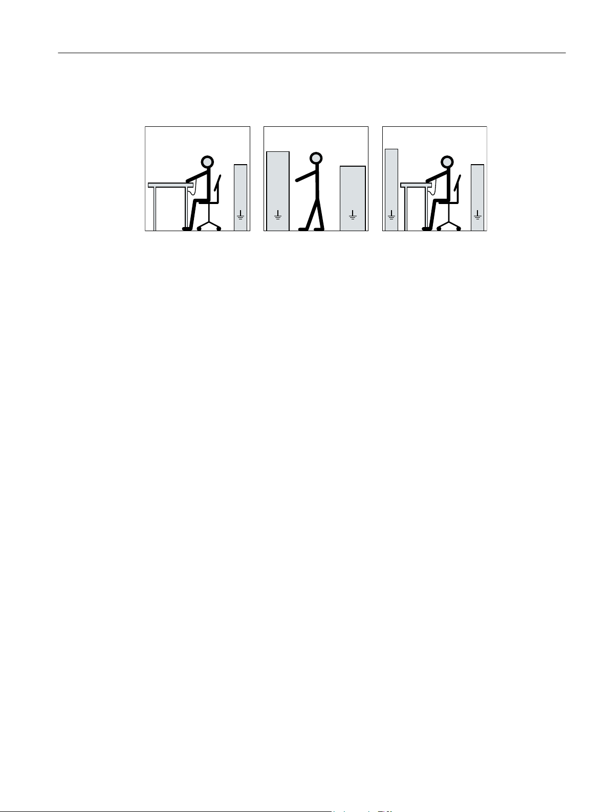
The necessary ESD protective measures for electrostatic sensitive devices are illustrated once
again in the following drawings:
a = conductive floor surfaceb = ESD table c = ESD shoes
d = ESD overall e = ESD wristband f = cabinet ground connection
2.7 Processes that generate high levels of electrostatic charge
Processes that generate high levels of electrostatic charge
Processes that generate high levels of electrostatic charge, which are far higher than those
generated through manual rubbing, include the following:
● Operation of high-voltage electrodes and ionizers
● Presence of high-speed particles on surfaces, e.g. sprayed charges (electron and ion flows)
in electrostatic coating processes
● Pneumatically conveyed dusts and bulk goods
● Flowing or hydraulically conveyed liquids and drops
● Belts, brushes and foils etc. moved by machines
Risk of explosion as a result of processes with high levels of electrostatic charging
Processes with high levels of electrostatic charging can result in propagating brush discharge/
brushing discharge and explosion
This can result in death, serious injury or material damage.
● Avoid all of these processes in areas where there is risk of gas and dust explosions at non-
metallic exposed components, e.g. paint finishes. These discharge types are not addressed
in current standards.
● The non-metallic exposed components, e.g. paint finishes are subject to an electrostatic
suitability test in the factory. When supplied, the motor has its original paint finish.
Use the tested, original paint when repainting or touching up. It is possible to use a paint that
has not been tested by Siemens, which is however suitable from an electrostatic
perspective. The operating company is responsible for carrying out an electrostatic test of
the complete system.
1PC134, 1PC136 crane motors SH 132 ... 315
Operating Instructions, 02/2019, A5E43212221A 15

Safety instructions
2.11 Special designs and construction versions
2.8 Electromagnetic compatibility
Electromagnetic compatibility
This machine is designed in accordance with IEC/EN 60034, and when used as prescribed it
satisfies the requirements of European Directive 2014/30/EU on Electromagnetic Compatibility.
2.9 Interference immunity
By selecting suitable signal cables and evaluation units, ensure that the interference immunity
of the machine is not diminished.
2.10 Interference voltages when operating the converter
Interference voltages when operating the converter
When a converter is in operation, the emitted interference varies in strength depending on the
converter (manufacturer, type, interference suppression measures undertaken). On machines
with integrated sensors (e.g. PTC thermistors), interference voltages caused by the converter
may occur on the sensor lead. This can cause faults which can result in eventual or immediate
death, serious injury or material damage.
● Comply with the EMC information provided by the manufacturer of the converter. This is how
you prevent the limit values stipulated by IEC/EN 61000-6-3 for the drive system (consisting
of the machine and converter) from being exceeded.
● You must put appropriate EMC measures in place.
2.11 Special designs and construction versions
Note
Before carry out any work on the machine, determine the machine version.
If there are any deviations or uncertainty, contact the manufacturer, specifying the type
designation and serial number (see the rating plate), or contact the Service Center (Page 109).
1PC134, 1PC136 crane motors SH 132 ... 315
16 Operating Instructions, 02/2019, A5E43212221A

Description
3.1 Area of application
The three-phase motors of this series are used as crane drives.
These motors are specifically designed for the following crane applications:
● STS (ship to shore) crane.
● ARTG (automated rubber tired gantry) crane.
● ARMG (automated rail mounted gantry) crane
● Straddle carrier crane
● Mobile STS crane
These machines have been designed for operation with frequency converters. They are
characterized by their high power density, ruggedness, long lifetime, and overall reliability.
Intended use of the machines
These machines are intended for industrial installations. They comply with the harmonized
standards of the series EN / IEC 60034 (VDE 0530). It is prohibited to use these motors in
hazardous zones if the marking on the motor rating plate does not explicitly permit line or
converter operation. If other/more wide-ranging demands (e.g. protection so that they cannot
be touched by children) are made in special cases – i.e. use in non-industrial installations –
these conditions must be ensured by the customer.
3
Note
Machine directive
Low-voltage motors are components designed for installation in machines in accordance with
the current Machinery Directive. Commissioning is prohibited until it has been absolutely
identified that the end product is in conformance with this Directive. Please observe the
EN / IEC 60204-1 standard.
3.1.1 CE marking
Use of machines without CE marking
Machines without CE marking are intended for operation outside the European Economic Area
(EEA). Do not use any machines without a CE marking in the EEA!
1PC134, 1PC136 crane motors SH 132 ... 315
Operating Instructions, 02/2019, A5E43212221A 17

Description
3.2 Rating plates
3.1.2 IE2 marking
Note
IE2 marking
Since January 1, 2017, according to REGULATION (EC) No. 640/2009, low-voltage motors
with power ratings above 0.75 kW up to 375 kW – and with efficiency IE2 – have this label.
This is mandatory within the European Economic Area (EEA). Customers are solely
responsible in ensuring the correct use.
When connecting the machine to a converter, carefully observe the rules and notes in Chapter
"Connecting a converter."
WARNING
Risk of explosion
This machine is not designed for use in hazardous areas. An explosion can occur if the
machine is operated in these areas. This can result in death, serious injury or material damage.
● Never operate this machine in hazardous areas.
3.1.3 Operating UL-certified machines with a converter
Operating a machine with a converter
Implement all machines of the overall machine-converter system according to UL-File E227215
assuming that the machines are only to be operated with a converter and are supplied with UL
certificate.
The company operating the equipment is responsible for implementing this in the actual
application.
3.2 Rating plates
Rating plate
The rating plate shows the identification data and the most important technical data. The data
on the rating plate and the contractual agreements define the limits of proper usage.
1PC134, 1PC136 crane motors SH 132 ... 315
18 Operating Instructions, 02/2019, A5E43212221A
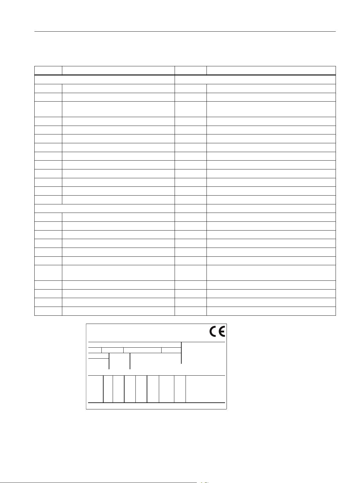
Data on the rating plate
(5) (6) (48)
(31)
(36) (38)(33) (37) (39) (40) (46)
(42)(18)
(41)
(19)
(12)
(7)
(16)
(10)
(11) (13)
(14) (15)
(20)
(21)
(17)
(49)
(52)
Item Description Item Description
General data Electrical data
1 Type of machine 31 Electrical data
2 Machine type 33 Rated voltage [V]
3 Serial number (incl. date of manufacture
YY.MM)
4 Standards 35 Frequency [Hz]
5 Additional details (optional) 36 Rated power [kW]
6 Customer data (optional) 37 Rated current [A]
7 Country of origin 38 Power factor [cosφ]
8 Production location 39 Rated speed [rpm]
10 Regulations (optional) 40 Efficiency class
49 Company logo 41 Efficiency
52 Marine regulation 42 Torque [Nm] (optional)
53 Motor family type 46 Operating mode (optional)
48 Anti-condensation heating (optional)
Mechanical data
11 Frame size
12 Type of construction
13 Degree of protection
14 Machine weight [kg]
15 Temperature class
16 Ambient temperature range (optional)
17 Installation altitude (only if higher than 1000 m)
34 Winding connections
Description
3.2 Rating plates
18 Vibration severity grade
19 Bearing sizes
20 Relubrication data/specifications (optional)
21 Brake data (optional)
1PC134, 1PC136 crane motors SH 132 ... 315
Operating Instructions, 02/2019, A5E43212221A 19

Description
3.3 Installation
3.3 Installation
3.3.1 Machine design
Motors of this series are low-voltage three-phase induction motors with a cylindrical shaft
extension and keyway. They can be supplied as single-speed machines with different
efficiency classes or as pole changing machines for several speeds.
In the case of machines with feet (IM B3 type of construction), the feet are cast or bolted on.
It is possible to change over the bolted on mounting feet on the machine enclosure, for example
to change the terminal box position; only authorized retrofit partners may carry out this work.
Measures for alignment and mounting (Page 47)
The regulations and standards used as basis to design and test this machine are stamped on
the rating plate. The machine design basically complies with the following standards:
Table 3-1 Applicable general regulations
Feature Standard
Dimensioning and operating behavior EN / IEC 60034-1
Procedure for determining the losses and the efficiency of rotating electrical machines
and inspections
Degree of protection EN / IEC 60034-5
Cooling EN / IEC 60034-6
Type of construction EN / IEC 60034-7
Terminal designations and direction of rotation EN / IEC 60034-8
Noise emission EN / IEC 60034-9
Starting characteristics of rotating electrical machines EN / IEC 60034-12
Vibration severity grades EN / IEC 60034-14
Efficiency classification of three-phase squirrel-cage induction motors EN / IEC 60034-30-1
IEC standard voltages IEC 60038
EN / IEC 60034-2-1
EN / IEC 60034-2-2
EN / IEC 60034-2-3
3.3.2 Cooling and ventilation
The machines of this series are three-phase induction machines with a closed primary
(internal) cooling circuit and an open secondary cooling circuit (surface cooling). The surface
cooling varies depending on the version.
1PC134, 1PC136 crane motors SH 132 ... 315
20 Operating Instructions, 02/2019, A5E43212221A
3.3.2.1 Motors with a fan
Self-ventilation (standard): Cooling method IC 411 according to EN / IEC 60034-6
Located at the ND end of the stator housing is an air intake cowl that guides the external air on
its way to the motor. The external air is drawn in through openings in the air intake cowl and
flows axially across the outer cooling ribs of the motor frame. The fan wheel for the external flow
of cooling air is attached to the machine shaft.
The fan wheels are bidirectional.
Check the cooling effect below rated speed in the case of frequent switching or braking – or if
the speed is controlled continually below the rated speed.
Description
3.3 Installation
Forced ventilation (optional): Type of cooling IC 416 in accordance with EN / IEC 60034-6
Cooling that does not depend on the speed is achieved by means of a unit that is independent
of the motor operating state (forced ventilation). This unit is closed to the outside by a fan cover.
It has its own main drive with fan impeller which creates the cooling air flow required for cooling
the motor.
1PC134, 1PC136 crane motors SH 132 ... 315
Operating Instructions, 02/2019, A5E43212221A 21

,&,&$$
Description
3.3 Installation
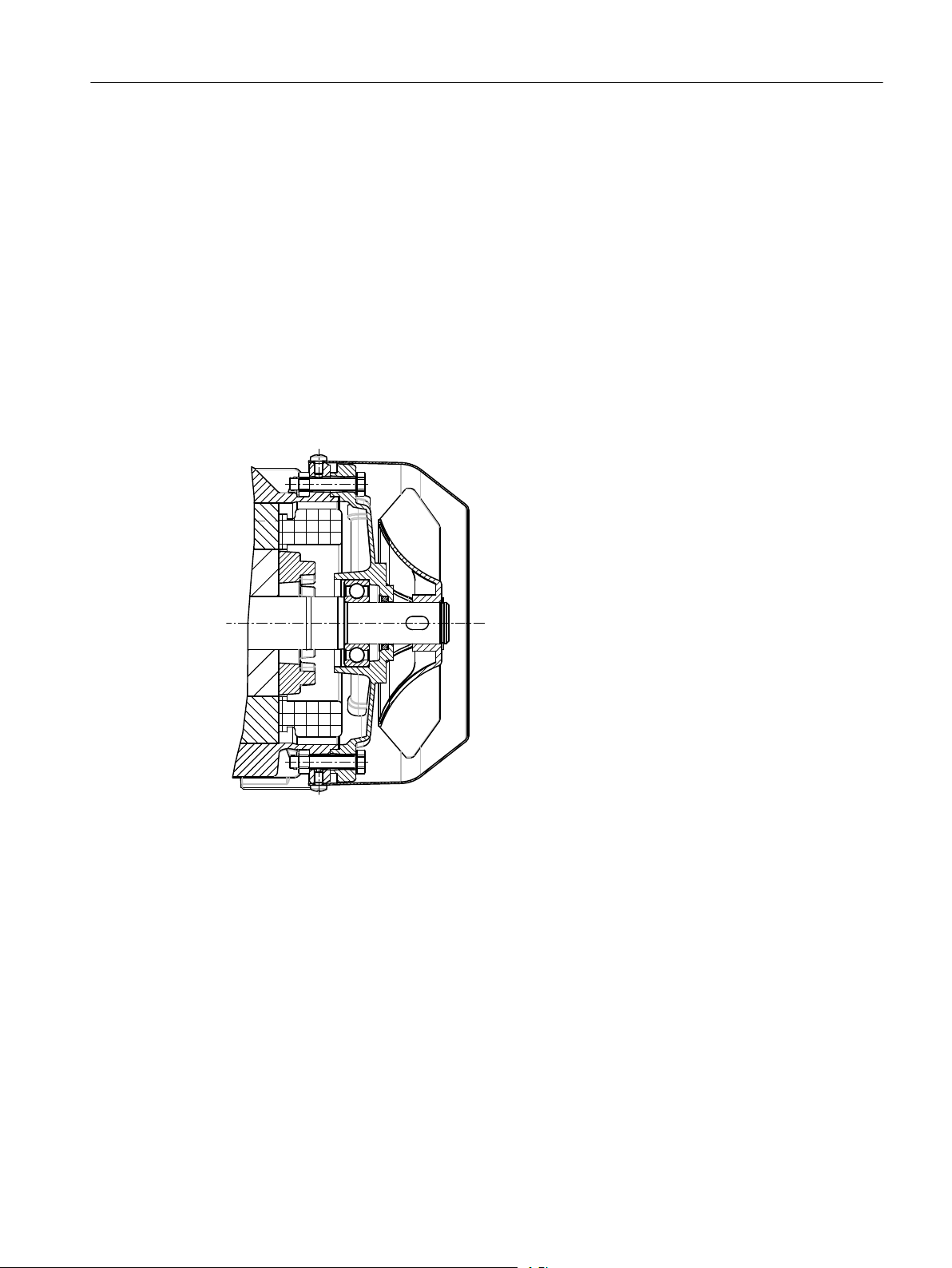
3.3.2.2 Machines without a fan
Surface cooling by free convection: Cooling method IC 410 according to EN / IEC 60034-6
Figure 3-1 IC410
3.3.3 Bearings
In order to support the machine shaft and maintain its position in the non-moving part of the
machine, only 2 rolling bearings are used. One rolling bearing performs the function of a
location bearing that transfers axial and radial forces from the rotating machine shaft to the nonmoving part of the machine. The second rolling bearing is implemented as floating and support
bearing in order to allow thermal expansion inside the machine and transfer radial forces.
The nominal (calculated) useful life of the bearings according to ISO 281 is at least 20,000
hours with utilization of the permissible radial/axial forces. However, the achievable useful life
of the bearings can be significantly longer in the case of lower forces (e.g. operation with selfaligning couplings).
22 Operating Instructions, 02/2019, A5E43212221A
Rolling bearings with permanent lubrication are maintenance-free.
1PC134, 1PC136 crane motors SH 132 ... 315

3.3.4 Balancing
As standard, the motor is balanced dynamically with a half feather key (code "H").
Vibration level "A" is standard and, if ordered as an option, vibration level B is specified on the
rating plate.
3.3.5 Types of construction/method of installation
The type of construction of the machine is stated on the rating plate.
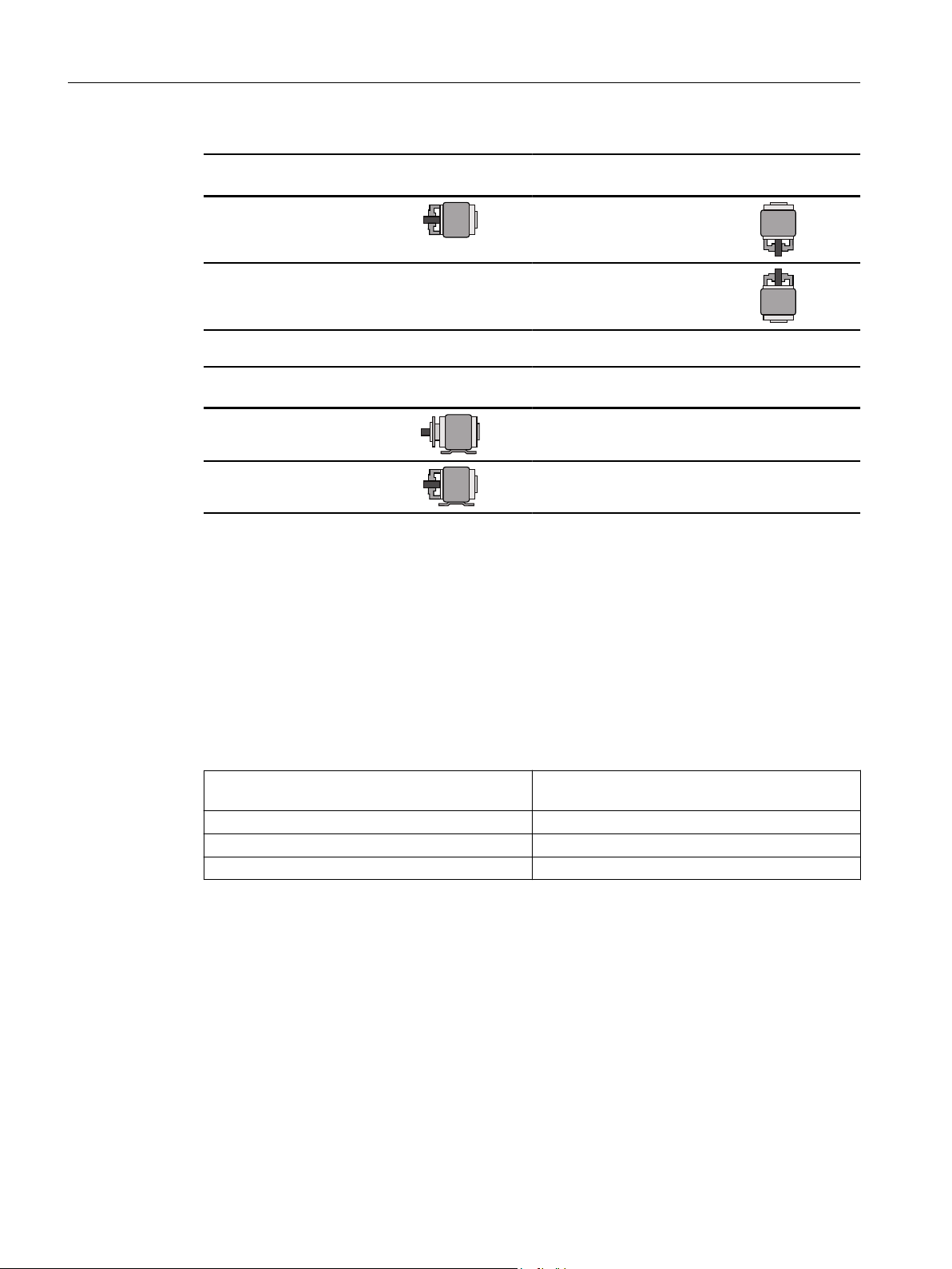
Table 3-2 Type of construction
Description
3.3 Installation
Basic type of construc‐
tion code
IM B3 (IM 1001) IM V5 (IM 1011)
IM V6 (IM 1031)
IM B6 (IM 1051)
IM B7 (IM 1061)
IM B8 (IM 1071)
Basic type of construc‐
tion code
IM B5 (IM 3001) IM V1 (IM 3011)
Diagram Other methods of instal‐
lation
Diagram Other methods of instal‐
lation
Diagram
Diagram
IM V3 (IM 3031)
1PC134, 1PC136 crane motors SH 132 ... 315
Operating Instructions, 02/2019, A5E43212221A 23
Description
3.3 Installation
Basic type of construc‐
tion code
IM B14 (IM 3601) IM V18 (IM 3611)
IM V19 (IM 3631)
Basic type of construc‐
tion code
IM B35 (IM 2001)
IM B34 (IM 2101)
3.3.6 Degree of protection
The machine has a type of protection as stamped on the rating plate, and can be installed in
dusty or humid environments.
Diagram Other methods of instal‐
lation
Diagram
Diagram
3.3.7 Environmental conditions
Limit values for the standard version
Relative humidity for ambient temperature
40 °C
Ambient temperature -20 °C to +40 °C
Installation altitude ≤ 1000 m
Air with normal oxygen content, usually 21 % (V/V)
The standard machines are not suitable for use in corrosive atmospheres, atmospheres with a
high salt content, or outdoor applications.
Limit values for the special versions
If the environmental conditions are different from the details listed here, then the values on the
rating plate or in the catalog will apply.
T
amb
Max. 55 %
1PC134, 1PC136 crane motors SH 132 ... 315
24 Operating Instructions, 02/2019, A5E43212221A

3.3.8 Optional built-on and built-in accessories
Supplementary devices
Depending on the order, various supplementary devices can be installed or mounted. These
include sensors for bearing temperature monitoring or winding monitoring, for example.
Machines can be equipped with the following integrated components/devices:
● Temperature sensors integrated in the stator winding in order to monitor the temperature
and protect the stator winding from overheating.
● Anti-condensation heating for machines whose windings are subject to a risk of
condensation due to the climatic conditions.
Machines can be equipped with the following mounted components/devices:
● Brake
● Rotary pulse encoder
● External fan (forced ventilation)
Description
3.3 Installation
● Measuring nipple for SPM shock pulse measurement for bearing monitoring
● Backstop
Note
Further documents
Observe all of the other documents provided with this machine.
3.3.9 Paint finish
Paint finish
The machine is painted according to the instructions in your order.
1PC134, 1PC136 crane motors SH 132 ... 315
Operating Instructions, 02/2019, A5E43212221A 25

Description
3.3 Installation
1PC134, 1PC136 crane motors SH 132 ... 315
26 Operating Instructions, 02/2019, A5E43212221A

Preparing for use
Good planning and preparation of machine applications are essential in terms of keeping
installation simple and avoiding errors, ensuring safe operation, and allowing access to the
machine for servicing and corrective maintenance.
This chapter outlines what you need to consider when configuring your plant in relation to this
machine and the preparations you need to make before the machine is delivered.
4.1 Safety-related aspects to consider when configuring the plant
A number of residual risks are associated with the machine. These are described in the chapter
titled "Safety information" (Page 11) and in related sections.
Take appropriate safety precautions (covers, barriers, markings, etc.) to ensure the machine is
operated safely within your plant.
4.2 Observing the operating mode
Observe the machine's operating mode. Use a suitable control system to prevent overspeeds,
thus protecting the machine from damage.
4
4.3 Delivery
Checking the delivery for completeness
The drive systems are put together on an individual basis. When you take receipt of the
delivery, please check immediately whether the items delivered are in accordance with the
accompanying documents. Siemens will not accept any claims relating to items missing from
the delivery and which are submitted at a later date.
● Report any apparent transport damage to the delivery agent immediately.
● Report any apparent defects/missing components to the appropriate SIEMENS office
immediately.
Archive the safety and commissioning notes provided in the scope of delivery as well as the
optionally available operating instructions so that these documents are always easily
accessible.
The rating plate optionally enclosed as a loose item with the delivery is provided to enable the
motor data to be attached on or near the machine or installation.
1PC134, 1PC136 crane motors SH 132 ... 315
Operating Instructions, 02/2019, A5E43212221A 27

Preparing for use
4.4 Transport and storage
4.4 Transport and storage
Observe the following when carrying out any work on the machine:
● Comply with the general safety instructions (Page 11).
● Comply with the applicable national and sector-specific regulations.
● When using the machine within the European Union, comply with the specifications laid
down in EN 50110‑1 regarding safe operation of electrical equipment.
WARNING
Risk of dropping and swinging when transported suspended
If you transport the motor suspended from cables or ropes, the cables or ropes can break, e.g.
as a result of damage. Further, if not adequately attached, the motor can swing. This can result
in death, serious injury, or material damage.
● Use additional, suitable lifting equipment for transport and during installation.
● Two cables alone must be able to carry the complete load.
● Prevent the lifting equipment from sliding by appropriately securing it.
● When using 2-cable lifting equipment, ensure that the maximum angle of inclination is ≤45°
according to ISO 3266 (DIN 580).
● Align the eyebolts so that the cables used for lifting are aligned with the planes of the
eyebolts.
WARNING
Toppling over or slipping of the motor
The motor can slide or topple over if it is not correctly lifted or transported. This can result in
death, serious injury, or material damage.
● Use all the lifting eyes on the machine.
● When using the lifting eyes on the machine, do not attach any additional loads or weight.
The lifting eyes are only designed for the weight of the machine itself.
● Any eyes that are screwed in must be tightly fastened.
● Eyebolts must be screwed in right up to their supporting surface.
● Comply with the permissible eyebolt loads.
● When necessary, use suitably dimensioned lifting equipment, for example hoisting straps
(EN1492-1) and load restraints (EN12195-2).
● Never remain under or in the immediate vicinity of the machine when it is lifted.
WARNING
Danger to life as a result of a machine falling
If the lifting gear or load handling attachments were to fail, the machine could fall. This can
result in death, serious injury or material damage.
● In order to gain easy and safe access to the underside of the machine, place it in a
secure and raised position.
1PC134, 1PC136 crane motors SH 132 ... 315
28 Operating Instructions, 02/2019, A5E43212221A
 Loading...