

Siemens SIMOTICS DC 1GH5, SIMOTICS DC 1GG6 Operating And Installation Instructions

Answers for industry.
SIMOTICS DC
DC motor
Type 1GH5
Operating Instructions / Installation Instructions
Edition 02/2016

08.02.2016 10:31
V4.00

SIMOTICS DC
DC motor
1GH5
Introduction
1
Operating Instructions
Installation Instructions
Safety notes
Description
Preparations for use
Assembling
Electrical connection
Commissioning
Operation
2
3
4
5
6
7
8
Maintenance
Spare Parts
Disposal
Service and Support
Technical data and drawings
Quality documents
Checklists
9
10
11
A
B
C
D
Edition 02/2016

Legal information
Warning notice system
This manual contains notices you have to observe in order to ensure your personal safety, as well as to prevent
damage to property. The notices referring to your personal safety are highlighted in the manual by a safety alert
symbol, notices referring only to property damage have no safety alert symbol. These notices shown below are
graded according to the degree of danger.
DANGER
indicates that death or severe personal injury will result if proper precautions are not taken.
WARNING
indicates that death or severe personal injury may result if proper precautions are not taken.
CAUTION
indicates that minor personal injury can result if proper precautions are not taken.
NOTICE
indicates that property damage can result if proper precautions are not taken.
If more than one degree of danger is present, the warning notice representing the highest degree of danger will be
used. A notice warning of injury to persons with a safety alert symbol may also include a warning relating to property
damage.
Qualified Personnel
The product/system described in this documentation may be operated only by personnel qualified for the specific
task in accordance with the relevant documentation, in particular its warning notices and safety instructions. Qualified
personnel are those who, based on their training and experience, are capable of identifying risks and avoiding
potential hazards when working with these products/systems.
Proper use of Siemens products
Note the following:
WARNING
Siemens products may only be used for the applications described in the catalog and in the relevant technical
documentation. If products and components from other manufacturers are used, these must be recommended or
approved by Siemens. Proper transport, storage, installation, assembly, commissioning, operation and
maintenance are required to ensure that the products operate safely and without any problems. The permissible
ambient conditions must be complied with. The information in the relevant documentation must be observed.
Trademarks
All names identified by ® are registered trademarks of Siemens AG. The remaining trademarks in this publication
may be trademarks whose use by third parties for their own purposes could violate the rights of the owner.
Disclaimer of Liability
We have reviewed the contents of this publication to ensure consistency with the hardware and software described.
Since variance cannot be precluded entirely, we cannot guarantee full consistency. However, the information in
this publication is reviewed regularly and any necessary corrections are included in subsequent editions.
Siemens AG
Process Industries and Drives
Postfach 48 48
90026 NÜRNBERG
GERMANY
Document order number: A5E33039795A AB
Ⓟ 02/2016 Subject to change
Copyright © Siemens AG 2016.
All rights reserved

Table of contents
1 Introduction.................................................................................................................................................11
1.1 About these instructions.........................................................................................................11
2 Safety notes................................................................................................................................................13
2.1 Information for the nominated person in control of the electrical installation.........................13
2.2 The five safety rules...............................................................................................................13
2.3 Qualified personnel................................................................................................................14
2.4 Safe handling.........................................................................................................................14
2.5 Electrostatic sensitive devices...............................................................................................16
2.6 Electromagnetic compatibility.................................................................................................17
2.7 Interference immunity.............................................................................................................17
2.8 Influence on the line power supply through a strongly irregular torque..................................17
2.9 Electromagnetic fields when operating electrical power engineering installations.................18
3 Description..................................................................................................................................................19
4 Preparations for use...................................................................................................................................23
4.1 Safety-related aspects to consider when configuring the plant..............................................23
4.2 Observing the operating mode...............................................................................................23
4.3 Noise emissions.....................................................................................................................23
4.4 Ensuring cooling.....................................................................................................................24
4.5 System-inherent frequencies.................................................................................................24
4.6 Torsional loading of the drive train due to faults in the electrical supply................................24
4.7 Transport and storage............................................................................................................25
4.7.1 Transport markings................................................................................................................25
4.7.2 Checking the delivery.............................................................................................................25
4.7.3 Attaching the rotor shipping brace prior to storage................................................................25
4.7.4 Checking the load handling attachments...............................................................................26
4.7.5 Requirements for safe lifting and transporting.......................................................................26
4.7.6 Transporting the machine set.................................................................................................28
4.7.7 Lifting and transporting the machine......................................................................................28
4.7.8 Storage...................................................................................................................................30
4.7.9 Protection against corrosion...................................................................................................32
5 Assembling.................................................................................................................................................33
5.1 Preparations for installation....................................................................................................33
5.1.1 Requirements for installation..................................................................................................33
5.1.2 Insulation resistance and polarization index..........................................................................34
5.1.3 Testing the insulation resistance and polarization index........................................................34
SIMOTICS DC 1GH5
Operating Instructions 02/2016 5

Table of contents
5.1.4 Preparing the mating faces....................................................................................................37
5.2 Lift the machine to where it will be installed, and position it...................................................37
5.2.1 Preconditions for correct alignment and secure attachment .................................................37
5.2.2 Checking the load handling attachments...............................................................................38
5.2.3 Removing the rotor shipping brace........................................................................................38
5.2.4 Removing anti-corrosion protection.......................................................................................39
5.2.5 Mounting the output elements................................................................................................40
5.2.6 Lifting and transporting the machine......................................................................................41
5.2.7 Putting the machine down......................................................................................................43
5.2.8 Drain condensate...................................................................................................................43
5.2.9 Roughly aligning the machine................................................................................................43
5.3 Installing the machine............................................................................................................44
5.3.1 Safety instructions for installation...........................................................................................44
5.3.2 Selecting fixing screws...........................................................................................................45
5.3.3 Preconditions for smooth, vibration-free operation................................................................45
5.3.4 Aligning the machine to the driven machine and attaching it to it (foundation mounting) ......45
5.3.5 Aligning the machine to the driven machine and attaching it to it (flange mounting,
vertical)...................................................................................................................................47
5.3.6 Aligning the machine to the driven machine and mounting (flange, horizontal IM B5)..........47
5.3.7 Mounting the machine............................................................................................................48
5.3.8 Axial and radial forces............................................................................................................48
6 Electrical connection...................................................................................................................................51
6.1 Selecting cables.....................................................................................................................51
6.2 Bringing in and routing the cables..........................................................................................51
6.3 Terminal designations............................................................................................................52
6.4 Connecting cables..................................................................................................................52
6.5 Connecting the main circuit....................................................................................................53
6.6 Connecting the grounding conductor.....................................................................................55
6.7 Internal equipotential bonding................................................................................................56
6.8 Connecting the auxiliary circuits.............................................................................................56
6.9 Connecting temperature monitoring for the stator winding....................................................57
6.10 Completing connection work..................................................................................................58
7 Commissioning...........................................................................................................................................59
7.1 Preparing for commissioning..................................................................................................59
7.2 Measure the insulation resistance before commissioning......................................................60
7.3 Greasing the roller bearings prior to commissioning..............................................................60
7.4 Minimum radial forces for cylindrical roller bearings..............................................................61
7.5 Switch on................................................................................................................................62
7.6 Overspeed..............................................................................................................................63
7.7 Switch off................................................................................................................................63
SIMOTICS DC 1GH5
6 Operating Instructions 02/2016

Table of contents
8 Operation....................................................................................................................................................65
8.1 Switching on the machine......................................................................................................66
8.2 Regreasing roller bearings.....................................................................................................67
8.3 Deactivating...........................................................................................................................67
8.4 Switching on again after an emergency switching-off............................................................67
8.5 Stoppages..............................................................................................................................67
8.5.1 Measures in non-operational periods.....................................................................................68
8.5.2 Avoidance of damage to roller bearings during stoppages....................................................69
8.5.3 Measurement of the insulation resistance after an extended stoppage.................................69
8.6 Decommissioning the machine..............................................................................................70
8.7 Re-commissioning the machine.............................................................................................70
8.8 Special operating conditions..................................................................................................70
8.9 Faults ....................................................................................................................................71
8.9.1 Inspections in the event of faults............................................................................................71
8.9.2 Faults in operation..................................................................................................................72
8.9.3 Roller bearing faults...............................................................................................................73
8.9.4 Brush faults............................................................................................................................74
8.9.5 Commutator faults..................................................................................................................75
9 Maintenance...............................................................................................................................................77
9.1 Inspection and maintenance..................................................................................................77
9.1.1 Initial inspection......................................................................................................................78
9.1.2 MTTR.....................................................................................................................................80
9.1.3 Main inspection......................................................................................................................80
9.1.4 Regreasing rolling-contact bearings.......................................................................................81
9.1.5 Regreasing intervals and grease types..................................................................................82
9.1.6 Clean the machine.................................................................................................................83
9.1.7 Checking the carbon brushes................................................................................................83
9.1.8 Replacing the carbon brushes...............................................................................................84
9.1.9 Setting the brush rocker and brush holder.............................................................................85
9.1.10 Maintaining the commutator...................................................................................................85
9.1.11 Maintaining terminal boxes....................................................................................................87
9.1.12 Touch up any damaged paintwork.........................................................................................88
9.2 Repair.....................................................................................................................................88
9.2.1 Prepare servicing work...........................................................................................................89
9.2.2 Disassembling the machine...................................................................................................90
9.2.3 Removing rolling-contact bearings.........................................................................................91
9.2.4 Installing the machine............................................................................................................91
9.2.5 Mounting the rolling-contact bearings....................................................................................92
9.2.6 Replacing the speed encoder................................................................................................93
9.2.6.1 Speed sensor with conical hub..............................................................................................93
9.2.6.2 Speed sensor for overhung mounting....................................................................................94
9.2.6.3 Speed sensor for construction type IM B5.............................................................................96
10 Spare Parts.................................................................................................................................................99
10.1 Ordering data.........................................................................................................................99
SIMOTICS DC 1GH5
Operating Instructions 02/2016 7

Table of contents
10.2 Ordering spare parts via the Internet...................................................................................100
10.3 Using commercially available spare parts............................................................................100
10.4 Stator and rotor....................................................................................................................101
10.5 Rolling-contact bearing........................................................................................................102
10.5.1 Rolling-contact bearing for 1G.5, 1H.5, shaft heights 500 to 630, drive end........................102
10.5.2 Rolling-contact bearing for 1G.5, 1H.5, shaft heights 500 to 630, non-drive end................103
10.6 Terminal boxes.....................................................................................................................104
10.6.1 1XB7710 main terminal box.................................................................................................104
10.6.2 1XB7942 main terminal box.................................................................................................105
10.6.3 Auxiliary terminal box...........................................................................................................106
10.7 Speed sensor.......................................................................................................................107
10.7.1 Shaft heights 180 to 630......................................................................................................107
10.7.1.1 Speed sensor with conical hub............................................................................................107
10.7.1.2 Speed sensor for overhung mounting..................................................................................108
10.7.1.3 Speed sensor for construction type IM B5...........................................................................109
11 Disposal....................................................................................................................................................111
11.1 Introduction..........................................................................................................................111
11.2 RoHS - restricting the use of certain hazardous substances...............................................111
11.3 Country-specific legislation..................................................................................................111
11.4 Dismantling the machine......................................................................................................111
11.5 Disposal of components.......................................................................................................112
A Service and Support.................................................................................................................................113
B Technical data and drawings....................................................................................................................115
B.1 Tightening torques for screw and bolt connections..............................................................115
C Quality documents....................................................................................................................................117
D Checklists.................................................................................................................................................119
D.1 Switching on.........................................................................................................................120
D.2 Commissioning.....................................................................................................................121
D.3 Inspection at standstill..........................................................................................................122
D.4 Inspection when the motor is running..................................................................................123
Index.........................................................................................................................................................125
Tables
Table 3-1 Insulation classes........................................................................................................................20
Table 3-2 Machine design ..........................................................................................................................20
Table 3-3 Data on the rating plate..............................................................................................................21
Table 4-1 Tightening torques for the shaft screw on the rotor shipping brace............................................29
Table 5-1 Stator winding insulation resistance at 40° C..............................................................................35
SIMOTICS DC 1GH5
8 Operating Instructions 02/2016

Table of contents
Table 5-2 Permissible deviations for aligning the machine with flexible coupling.......................................46
Table 6-1 Terminal designations in example B1.........................................................................................52
Table 6-2 Terminal box connection data.....................................................................................................53
Table 6-3 Tightening torque of screws with cable lugs................................................................................55
Table 6-4 Tightening torque of screws with ground terminals.....................................................................56
Table 7-1 Minimum radial forces.................................................................................................................62
Table 8-1 Vibration magnitude as a function of vibration frequency............................................................67
Table 8-2 Faults in operation.......................................................................................................................72
Table 8-3 Roller bearing faults ...............................................................................................................73
Table 8-4 Brush faults.................................................................................................................................74
Table 8-5 Commutator faults.......................................................................................................................75
Table 9-1 MTTR in fault-free operation ......................................................................................................80
Table 9-2 Suitable greases for rolling-contact bearings (down to -20 °C)...................................................82
Table 9-3 Commutator overhaul – minimum permissible diameter.............................................................86
Table 9-4 Recommended torques for tightening the shaft journal...............................................................93
Table 9-5 Recommended torques for tightening the shaft journal...............................................................95
Table 9-6 Recommended torques for tightening the coupling.....................................................................96
Table 9-7 Tightening torques for mounting couplings.................................................................................97
Table 10-1 Spare parts stator and rotor 1G.5, 1H.5, shaft heights 500 to 630...........................................101
Table 10-2 Spare parts rolling-contact bearing for 1G.5, 1H.5, shaft heights 500 to 630...........................102
Table 10-3 Spare parts rolling-contact bearing for 1G.5, 1H.5, shaft heights 500 to 630...........................103
Table 10-4 Spare parts main terminal box 1XB7710...................................................................................104
Table 10-5 Spare parts main terminal box 1XB7942...................................................................................105
Table 10-6 Spare parts auxiliary terminal box.............................................................................................106
Table 10-7 Spare parts speed sensor with conical hub for shaft heights 180 to 630..................................107
Table 10-8 Spare parts speed sensor for overhung mounting for shaft heights 180 to 630.......................108
Table 10-9 Spare parts speed sensor for construction type IM B5 for shaft heights 180 to 630.................109
Table B-1 Tightening torques for screw/bolt connections with a tolerance of ±10%.................................115
Table D-1 Items to check during switch-on................................................................................................120
Table D-2 Items to check during commissioning.......................................................................................121
Table D-3 Items to inspect when machine is at standstill..........................................................................122
Table D-4 Items to inspect when the motor is running...............................................................................123
Images
Image 3-1 Block diagram of motor type 1GH...............................................................................................19
Image 3-2 Schematic rating plate.................................................................................................................21
Image 4-1 Rotor shipping brace without coupling (1) and with coupling (2). ...............................................28
Image 5-1 Balancing type on the drive-end side..........................................................................................40
SIMOTICS DC 1GH5
Operating Instructions 02/2016 9

Table of contents
Image 5-2 Schematic diagram: Aligning the machine to the driven machine...............................................46
Image 6-1 Connection of main terminals with cable lug...............................................................................54
Image 6-2 Connection of auxiliary terminals with cable lug..........................................................................54
Image 6-3 Connection without cable lugs.....................................................................................................54
Image 9-1 Adjusting the brush rocker: fixed part (1), brush rocker (2).........................................................85
Image 9-2 Reworking the slots.....................................................................................................................87
Image 9-3 Final work on the commutator after skimming.............................................................................87
Image 9-4 Speed sensor assembly .............................................................................................................94
Image 9-5 Speed sensor assembly .............................................................................................................95
Image 9-6 Speed encoder mounting............................................................................................................97
Image 10-1 Stator and rotor 1G.5, 1H.5, shaft heights 500 to 630...............................................................101
Image 10-2 Rolling-contact bearing for 1G.5, 1H.5, shaft heights 500 to 630.............................................102
Image 10-3 Rolling-contact bearing for 1G.5, 1H.5, shaft heights 500 to 630.............................................103
Image 10-4 Main terminal box 1XB7710 .....................................................................................................104
Image 10-5 Main terminal box 1XB7942 .....................................................................................................105
Image 10-6 Auxiliary terminal box................................................................................................................106
Image 10-7 Speed sensor with conical hub for shaft heights 180 to 630.....................................................107
Image 10-8 Speed sensor for overhung mounting for shaft heights 180 to 630..........................................108
Image 10-9 Speed sensor for construction type IM B5 for shaft heights 180 to 630....................................109
SIMOTICS DC 1GH5
10 Operating Instructions 02/2016

Introduction
1.1 About these instructions
These instructions describe the machine and explain how to handle it, from initial delivery to
final disposal of the equipment. Keep these instructions for later use.
Read these operating instructions before you handle the machine and follow the instructions
to become familiar with its design and operating principles and thus ensure safe, problem-free
machine operation and long service life.
Please contact the Service Center (Page 113) if you have any suggestions on how to improve
this document.
Text format features
The warning notice system is explained on the rear of the inside front. Always follow the safety
instructions and notices in these instructions.
In addition to the safety-related warning notices which you must read, you will find the text in
these instructions is formatted in the following way:
1. Handling instructions are always formatted as a numbered list. Always perform the steps
in the order given.
1
● Lists are formatted as bulleted lists.
– Lists on the second level are hyphenated.
Note
A Note is an important item of information about the product, handling of the product or the
relevant section of the document. Notes provide you with help or further suggestions/ideas.
SIMOTICS DC 1GH5
Operating Instructions 02/2016 11

Introduction
1.1 About these instructions
SIMOTICS DC 1GH5
12 Operating Instructions 02/2016

Safety notes
2.1 Information for the nominated person in control of the electrical installation
This electric machine has been designed and built in accordance with the specifications
contained in Directive 2006/95/EC up to April 19, 2016 - and from April 20, 2016 according to
Directive 2014/35/EU ("Low-Voltage Directive") and is intended for use in industrial plants.
Please observe the country-specific regulations when using the electric machine outside the
European Community. Follow the local and industry-specific safety and setup regulations.
The persons responsible for the plant must ensure the following:
● Planning and configuration work and all work carried out on and with the machine is only
to be done by qualified personnel.
● The operating instructions must always be available for all work.
● The technical data as well as the specifications relating to the permissible installation,
connection, ambient and operating conditions are taken into account at all times.
● The specific setup and safety regulations as well as regulations on the use of personal
protective equipment are observed.
Note
2
Use the services and support provided by the appropriate Service Center (Page 113) for
planning, installation, commissioning, and servicing work.
You will find safety instructions in the individual sections of this document. Follow the safety
instructions for your own safety, to protect other people and to avoid damage to property.
Observe the following safety instructions for all activities on and with the machine.
2.2 The five safety rules
For your own personal safety and to prevent material damage when carrying out any work,
always observe the safety-relevant instructions and the following five safety rules according
to EN 50110‑1 "Working in a voltage-free state". Apply the five safety rules in the sequence
stated before starting work.
Five safety rules
1. Disconnect the system.
Also disconnect the auxiliary circuits, for example, anti-condensation heating.
2. Secure against reconnection.
3. Verify absence of operating voltage.
SIMOTICS DC 1GH5
Operating Instructions 02/2016 13
Safety notes
2.4 Safe handling
4. Ground and short-circuit.
5. Provide protection against adjacent live parts.
To energize the system, apply the measures in reverse order.
2.3 Qualified personnel
All work at the machine must be carried out by qualified personnel only. For the purpose of
this documentation, qualified personnel is taken to mean people who fulfill the following
requirements:
● Through appropriate training and experience, they are able to recognize and avoid risks
and potential dangers in their particular field of activity.
● They have been instructed to carry out work on the machine by the appropriate person
responsible.
2.4 Safe handling
Workplace safety depends on the attentiveness, care, and common sense of the personnel
who install, operate, and maintain the machine. In addition to the safety measures cited, as a
matter of principle, the use of caution is necessary when you are near the machine. Always
pay attention to your safety.
Also observe the following to prevent accidents:
● General safety regulations applicable in the country where the machine is deployed.
● Manufacturer-specific and application-specific regulations
● Special agreements made with the operator
● Separate safety instructions supplied with the machine
● Safety symbols and instructions on the machine and its packaging
WARNING
Live parts
Electric machines contain live parts.
Fatal or severe injuries and substantial material damage can occur if the covers are removed
or if the machine is not handled, operated, or maintained properly.
● Always observe the “five safety rules" (Page 13) when carrying out any work on the
machine.
● Only remove the covers using the methods described by these operating instructions.
● Operate the machine properly.
● Regularly and correctly maintain the machine.
SIMOTICS DC 1GH5
14 Operating Instructions 02/2016
Safety notes
2.4 Safe handling
WARNING
Rotating parts
Electric machines contain dangerous rotating parts.
Fatal or severe injuries and substantial material damage can occur if the covers are removed
or if the machine is not handled, operated, or maintained properly.
● Only remove the covers using the methods described by these operating instructions.
● Operate the machine properly.
● Regularly and correctly maintain the machine.
● Secure free-standing shaft ends and other rotating parts such as couplings, belt pulleys
etc. against touch.
WARNING
Hot surfaces
Electric machines have hot surfaces. Do not touch these surfaces. They could cause burns.
● Allow the machine to cool before starting work on the machine.
● Only remove the covers using the methods described by these operating instructions.
● Operate the machine properly.
CAUTION
Hazardous substances
Chemical substances required for the setup, operation and maintenance of machines can
present a health risk.
Poisoning, skin damage, cauterization of the respiratory tract, and other health damage may
result.
● Read the information in these operating instructions and the product information supplied
by the manufacturer.
● Observe the relevant safety regulations and wear the personal protective equipment
specified.
CAUTION
Flammable substances
Chemical substances required for the setup, operation and maintenance of machines may
be flammable.
Burns and other damage to health and material may result.
● Read the information in these operating instructions and the product information supplied
by the manufacturer.
● Observe the relevant safety regulations and wear the personal protective equipment
specified.
SIMOTICS DC 1GH5
Operating Instructions 02/2016 15

Safety notes
2.5 Electrostatic sensitive devices
WARNING
Noise emissions
During operation, the machine's noise emission levels can exceed those permitted at the
workplace, which can cause hearing damage.
Take steps to reduce noise, such as introducing covers and protective insulation or adopting
hearing protection measures, so that the machine can be operated safely within your system.
2.5 Electrostatic sensitive devices
ESD protective measures
NOTICE
Electrostatic discharge
Electronic modules contain components that can be destroyed by electrostatic discharge.
These modules can be easily destroyed by improper handling.
To protect equipment against damage, follow the instructions given below.
● Only touch electronic modules if you absolutely have to work on them.
● The body of the person concerned must have been electrostatically discharged and
grounded immediately before any electronic modules are touched.
● Electronic modules should not be brought into contact with electrically insulating materials,
such as:
– Plastic film
– Plastic parts
– Insulating table supports
– Clothing made of synthetic fibers
● Always place electrostatic sensitive devices on conductive bases.
● Always pack, store and transport electronic modules or components in conductive
packaging, such as:
– Metallized plastic or metal containers
– Conductive foam material
– Domestic aluminum foil
SIMOTICS DC 1GH5
16 Operating Instructions 02/2016
Safety notes
2.8 Influence on the line power supply through a strongly irregular torque
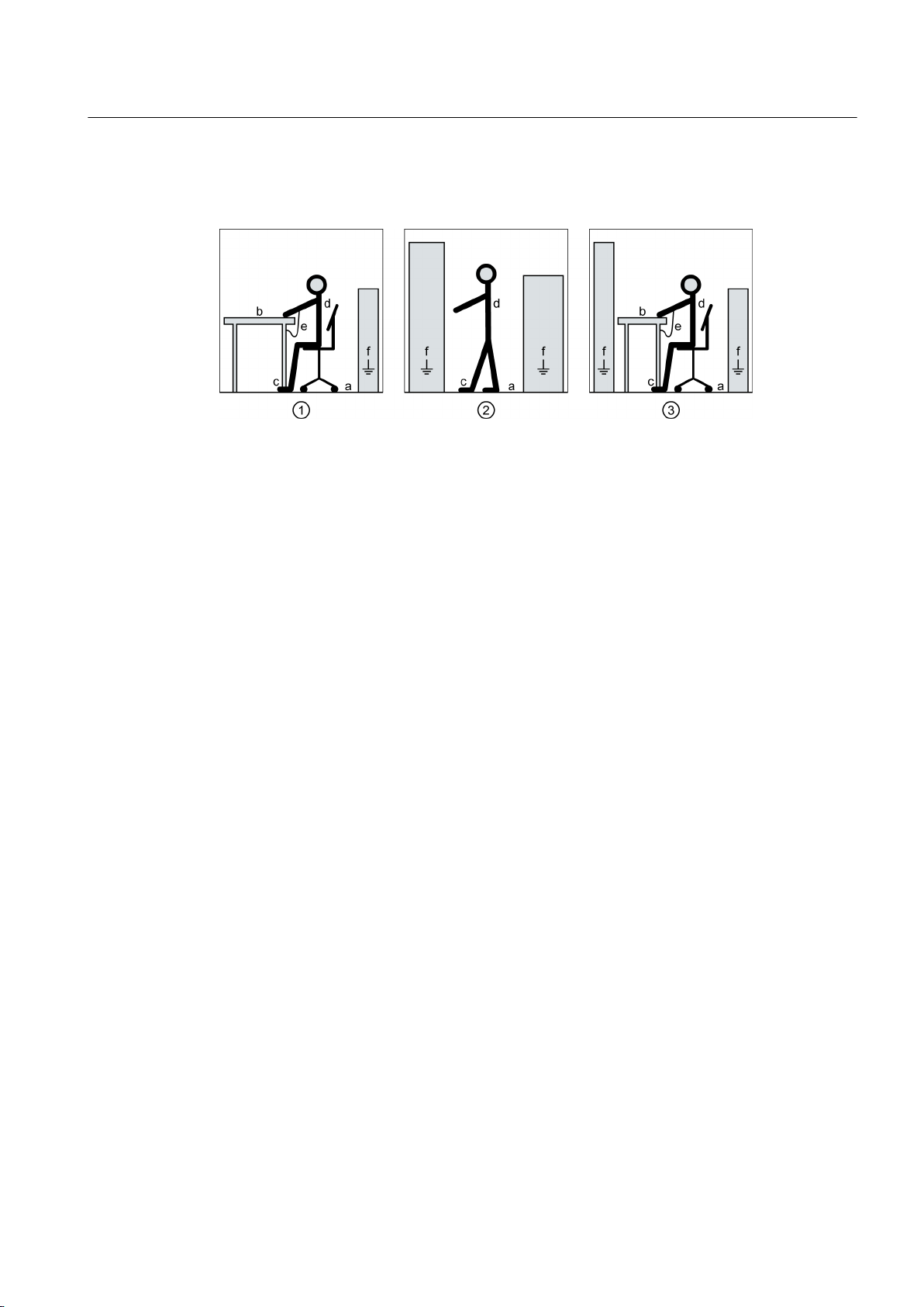
The necessary ESD protective measures for electrostatic sensitive devices are illustrated once
again in the following drawings:
(1) Sitting (2) Standing (3) Standing/sitting
a = conductive floor surface b = ESD table c = ESD shoes
d = ESD overall e = ESD wristband f = cabinet ground connection
2.6 Electromagnetic compatibility
This machine is designed in accordance with IEC/EN 60034 and, when used as prescribed, it
satisfies the requirements of European Directive 2004/108/EC - from April 20, 2016 of the
European directive 2014/30/EU on Electromagnetic Compatibility.
2.7 Interference immunity
The machine fulfills the requirements regarding interference immunity in conformity with IEC/
EN 61000‑6‑2.
On machines with integrated sensors (e.g. PTC thermistors), the manufacturer of the overall
system must himself ensure sufficient interference immunity by selecting suitable sensor signal
leads and evaluation units.
2.8 Influence on the line power supply through a strongly irregular torque
A strongly irregular torque, for example with the drive of a reciprocating motor, forces a nonsinusoidal motor current. The emerging harmonics can have an impermissible influence on
the line power supply via the connection lines.
SIMOTICS DC 1GH5
Operating Instructions 02/2016 17

Safety notes
2.9 Electromagnetic fields when operating electrical power engineering installations
2.9 Electromagnetic fields when operating electrical power engineering
installations
WARNING
Interference to electronic devices caused by electrical power equipment
Electrical power equipment generate electric fields during operation. Potentially lethal
malfunctions can occur in medical implants, e.g. pacemakers, in the vicinity of electrical power
equipment. Data may be lost on magnetic or electronic data carriers.
● It is forbidden for people with pacemakers to enter the vicinity of the machine.
● Protect the personnel working in the plant by taking appropriate measures, such as
erecting identifying markings, safety barriers and warning signs and giving safety talks.
● Observe the nationally applicable health and safety regulations.
● Do not carry any magnetic or electronic data media.
SIMOTICS DC 1GH5
18 Operating Instructions 02/2016
Description
Applications
DC machine of the 1GH5... series are implemented with open-circuit or closed-circuit cooling
with a laminated stator yoke.
They are designed for a wide range of drive and energy conversion applications and comply
with the harmonized standards of series IEC / EN 60034 (VDE 0530).
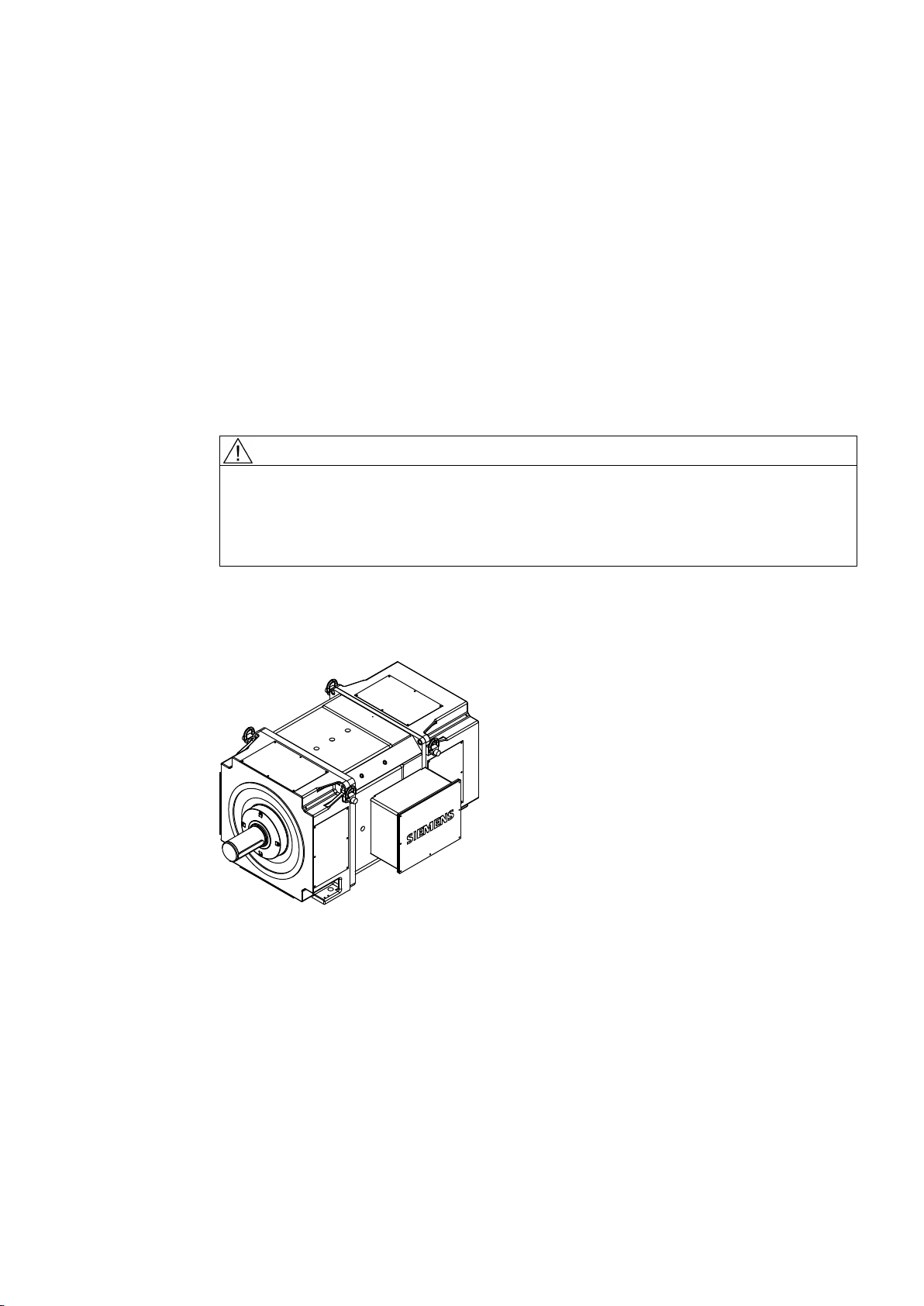
Schematic diagram
3
WARNING
Risk of explosion
This machine is not designed for use in hazardous areas. An explosion can occur if the
machine is operated in these areas. This can result in death, serious injury or material damage.
Never operate this machine in hazardous areas.
Image 3-1 Block diagram of motor type 1GH...
Cooling
The forced-ventilated machine is open-circuit-ventilated with cooling method IC 17, with pipe
connections on both sides with cooling method IC 37. The external fan is connected to the
machine via a pipe. The fan and cooling pipe are not included in the scope of supply.
SIMOTICS DC 1GH5
Operating Instructions 02/2016 19

Description
Design
Insulation system
The machine has no housing, but is designed with a fully laminated stator yoke which allows
a rate of current change of up to 250 IN/sec.
The high-quality DURIGNIT® 2000 insulation system means that the motors are suitable for
use in both tropical humidity and industrial environments. You will find the insulation classes
in the following table.
Table 3-1 Insulation classes
Series Insulation class
1GG5
1GH5
1HS5
1HQ5
1GG6, 1GG7
1GH6, 1GH7
1HS6, 1HS7
1HQ6, 1HQ7
155 (F)
180 (H)
Degree of protection
With a pipe connection on one side, the machine has degree of protection IP23; with pipe
connections on both sides, it has degree of protection IP54.
Ambient conditions
Unless otherwise specified, the rated powers apply for continuous operation at a coolant
temperature of ≤ 40 °C and an installation altitude of up to 1000 m above sea level. Please
note any data to the contrary on the rating plate. Operating conditions must comply with the
specifications on the rating plate.
Machine design
You will find regulations and standards for rating and testing this motor on the rating plate. The
machine design basically complies with the following standards. Please refer to the EC or EU
Declaration of Conformity for the versions of the harmonized standards referenced.
Table 3-2 Machine design
Characteristic Standard
Ratings and operating performance IEC/EN 60034‑1
Degree of protection IEC/EN 60034‑5
SIMOTICS DC 1GH5
20 Operating Instructions 02/2016
Rating plate
1
2
3
4
5
6
7
8
9
10
11
12
13
14
15
16
Description
Characteristic Standard
Cooling IEC/EN 60034‑6
Construction type IEC/EN 60034‑7
Terminal markings and direction of rotation IEC/EN 60034‑8
Noise emission IEC/EN 60034‑9
Vibration severity grades IEC/EN 60034‑14
Vibration limits DIN ISO 10816-3
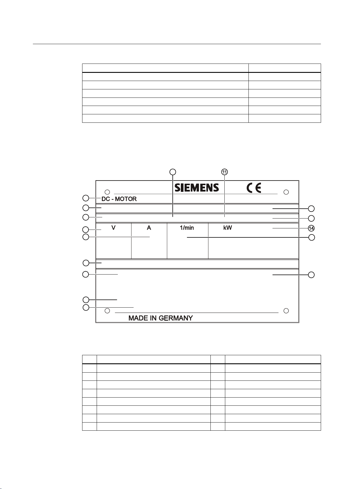
The rating plate shows the identification data and the most important technical data. The data
on the rating plate and the contractual agreements define the limits of proper usage.
Image 3-2 Schematic rating plate
Table 3-3 Data on the rating plate
Item Description Item Description
① Type ⑨ Supply connection data
② Serial number ⑩ Degree of protection
③ Temperature class ⑪ Construction type
④ Armature voltage [V] ⑫ Standards and regulations
⑤ Armature current [A] ⑬ Motor weight [t]
⑥ Exciter data ⑭ Power [kW]
⑦ Cooling method ⑮ Speed [RPM]
SIMOTICS DC 1GH5
Operating Instructions 02/2016 21
⑧ Brush equipment ⑯ Air flow direction

Description
Terminal box
The terminal box contains terminals for the main circuit and auxiliary circuit (excitation) and
for other auxiliary circuits. The terminal box fulfills degree of protection IP55.
The screw-mounted entry plate is not normally supplied with holes. This enables you to adapt
the type, number, and size of the screw connections to the specific cabling requirements.
If a separate wiring space is prescribed for specific auxiliary circuits, an additional auxiliary
terminal box is mounted on the side of the terminal box.
Rolling-contact bearing
The rolling-contact bearing is normally a floating bearing at the drive end and a locating bearing
at the non-drive end. You will find further information in section "Spare parts (Page 99)."
On machines with a regreasing device, the lubricant plate specifies the types of rolling-contact
bearing fitted.
SIMOTICS DC 1GH5
22 Operating Instructions 02/2016

Preparations for use
Good planning and preparation of machine applications are essential in terms of keeping
installation simple and avoiding errors, ensuring safe operation, and allowing access to the
machine for servicing and corrective maintenance.
This chapter outlines what you need to consider when configuring your plant in relation to this
machine and the preparations you need to make before the machine is delivered.
4.1 Safety-related aspects to consider when configuring the plant
A number of residual risks are associated with the machine. These are described in the chapter
titled "Safety information" (Page 13) and in related sections.
Take appropriate safety precautions (covers, barriers, markings, etc.) to ensure the machine
is operated safely within your plant.
4.2 Observing the operating mode
Observe the machine's operating mode. Use a suitable control system to prevent overspeeds,
thus protecting the machine from damage.
4
4.3 Noise emissions
WARNING
Noise emissions
During operation, the machine's noise emission levels can exceed those permitted at the
workplace, which can cause hearing damage.
Take steps to reduce noise, such as introducing covers and protective insulation or adopting
hearing protection measures, so that the machine can be operated safely within your system.
SIMOTICS DC 1GH5
Operating Instructions 02/2016 23

Preparations for use
4.6 Torsional loading of the drive train due to faults in the electrical supply
4.4 Ensuring cooling
Ensure that the machine is sufficiently cooled by the cooling air flow at the installation site:
● Ensure that the cooling air can flow in and out unobstructed. The full air flow provided by
the fan is only possible if air can freely enter the impeller. In the axial direction, ensure a
clearance of at least 1 x air intake diameter.
● Make sure that the machine does not draw in the hot discharged air again.
● For machines with a vertical type construction with an air intake from above, ensure that
the air inlets are protected against the ingress of foreign bodies and water.
4.5 System-inherent frequencies
NOTICE
Machine damage caused by system resonances
The system consisting of the foundation and machine set must be configured and matched
in such a way that no system resonances can arise and result in the permissible vibration
levels being exceeded. Excessive vibrations can damage the machine set. The vibration limit
values according to DIN ISO 10816-3 must not be exceeded.
4.6 Torsional loading of the drive train due to faults in the electrical supply
In the event of faults in the electrical supply, such as failure of the field supply or short circuit
across terminals, excessive air gap torques can occur, which can lead to additional torsional
loads on the drive train.
WARNING
Serious damage to the machine
If the configuration does not correctly recognize the mechanical torsional loadings of the shaft
assembly, this can lead to serious damage to the machine. This can result in death, serious
injury or material damage.
When planning the system, make due allowance for the maximum air gap torques that can
occur.
Note
The system planner is responsible for the entire drive train.
SIMOTICS DC 1GH5
24 Operating Instructions 02/2016
4.7 Transport and storage
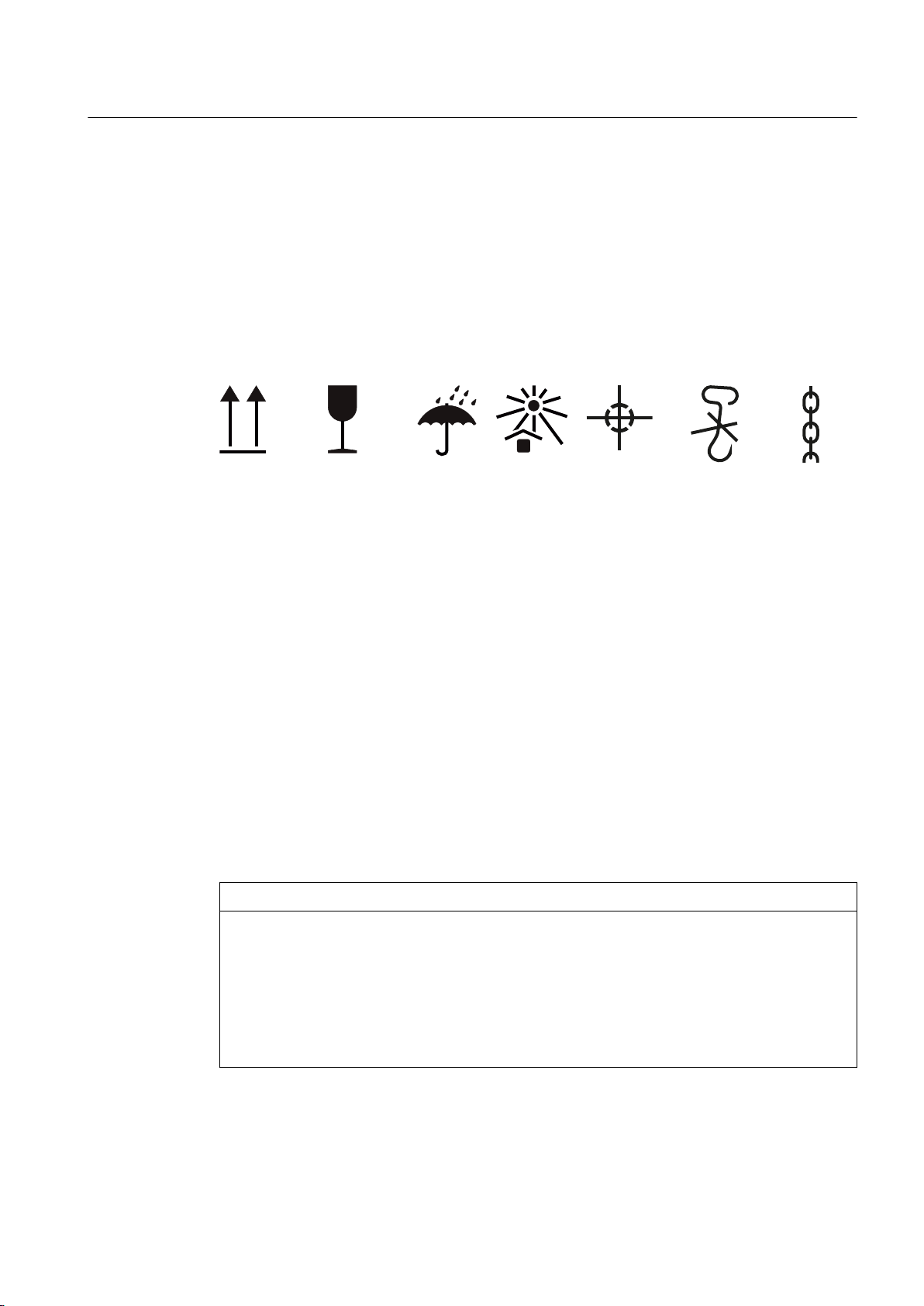
4.7.1 Transport markings
The packing differs depending on the transport type and size. If not otherwise contractually
agreed, the packaging corresponds to the packing guidelines for International Standards for
Phytosanitary Measures (ISPM).
Comply with the images shown on the packaging. Their meaning is as follows:
Preparations for use
4.7 Transport and storage
This
way up
Fragile goods Keep dry Keep cool Center of
4.7.2 Checking the delivery
The components are assembled on an individual basis. When you take receipt of the delivery,
please check immediately whether the scope of the delivery matches up with the
accompanying documents. No claims relating to defects/items missing from the delivery will
be accepted if they are submitted at a later date.
● Report any apparent transport damage to the delivery agent immediately.
● Immediately report any apparent defects/missing components to your contact partner.
These Operating Instructions are part of the scope of delivery; keep them in a location where
they can be easily accessed.
4.7.3 Attaching the rotor shipping brace prior to storage
NOTICE
Bearing damage caused by vibration
gravity
Do not use
hand hook
Attach here
If storage conditions are inappropriate there is a risk of bearing seizure damage. This can
result in material damage, such as damage to bearings caused by vibration.
● On machines that have been supplied with a rotor shipping brace, secure the rotor as per
the notes on transportation.
● Protect the machine against strong radial vibrations, since the rotor shipping brace might
not absorb these completely.
SIMOTICS DC 1GH5
Operating Instructions 02/2016 25

Preparations for use
4.7 Transport and storage
NOTICE
Bearing damage when being transported
If the customer has already mounted parts, for example coupling, belt pulley, etc., the bearing
can be damaged during transport.
● In this case, make sure that the customer uses a rotor shipping brace.
4.7.4 Checking the load handling attachments
Inspect the load handling attachments such as the load stands, lifting eyes and ring bolts and
also the lifting gear, before lifting the machine:
● Inspect the load handling attachments on the machine for possible damage. Replace any
load handling attachments that are found to be damaged.
● Check before use that the load handling attachments are correctly secured.
● When lifting the machine, use only approved and undamaged lifting gear of sufficient rated
capacity. Check these before using them.
WARNING
The machine can be dropped
If the load handling attachments and lifting gear are damaged or not correctly secured,
the machine may be dropped during lifting. This can result in death, serious injury or
material damage. Inspect the load handling attachments and lifting gear before use.
4.7.5 Requirements for safe lifting and transporting
To safely lift and transport the machine, the following requirements must be met:
● Personnel operating cranes and fork-lift trucks must be appropriately qualified.
● If the motor is packed, depending on the weight, size and on-site conditions, lift crates and
transport frames using a fork-lift truck or a crane with slings.
– Use a crane or fork-lift truck suitable for the load.
– The center of gravity of the goods and the positions of the hoisting points are indicated
on the packaging. Do not hoist any goods with damaged packaging.
● When lifting the machine, use only approved and undamaged sling guides and spreaders
of sufficient rated capacity. Check the lifting equipment prior to its use. The weight of the
machine is shown on the rating plate.
SIMOTICS DC 1GH5
26 Operating Instructions 02/2016

Preparations for use
4.7 Transport and storage
● When lifting the machine, refer to the information on the lifting plate.
– Comply with the specified spreading angles.
– Do not exceed the maximum lifting acceleration and lifting speed specified on the lifting
plate. Lift the machine without jerking it.
Acceleration a ≤ 0.4 g (≈ 4 m/s2)
Velocity v ≤ 20 m/min
● Use only the load carrying device on the stator frame for lifting.
WARNING
The machine can tip over, slip or fall down during transport if a different construction is used
If you do not transport or lift the machine in a position appropriate for its construction, the
machine can tip, slip into the lifting equipment or fall down. This can result in death, serious
injury or material damage.
● Use only the load carrying device on the stator frame for lifting.
● Use the load carrying device appropriate for the machine position.
● Use suitable rope guiding or spreading devices. The weight of the machine is shown on
the rating plate.
WARNING
The machine can fall over, shift or fall down during transport if the center of gravity is not
symmetrical
If the center of gravity of a load is not located centrally between the attachment points, the
motor can tip over or slip out of the lifting equipment and fall when it is being transported or
lifted. This can result in death, serious injury or material damage.
● Comply with the handling instructions on the machine when transporting it.
● Be aware of the possibility of different loads on the sling ropes or lifting straps and the
carrying capacity of the lifting equipment.
● Always take account of the center of gravity when transporting or lifting the motor. If the
center of gravity is not located centrally between the attachment points, then position the
hoisting hook above the center of gravity.
SIMOTICS DC 1GH5
Operating Instructions 02/2016 27
ཱི
ཱ
ཱི
ི
Preparations for use
4.7 Transport and storage
4.7.6 Transporting the machine set
WARNING
Falling down of the machine
The lifting lugs on the machine are designed only for the weight of the machine. If a machine
set is lifted and transported on a single machine, this can lead to mechanical failure of the
lifting lug. The machine or machine set may fall. This can result in death, serious injury or
material damage.
● Do not lift machine sets by attaching lifting tackle to the individual machines.
● Use only the equipment provided, e.g. the openings or lugs on the base plates, for
transporting machine sets. Note the maximum capacity of the lifting lug.
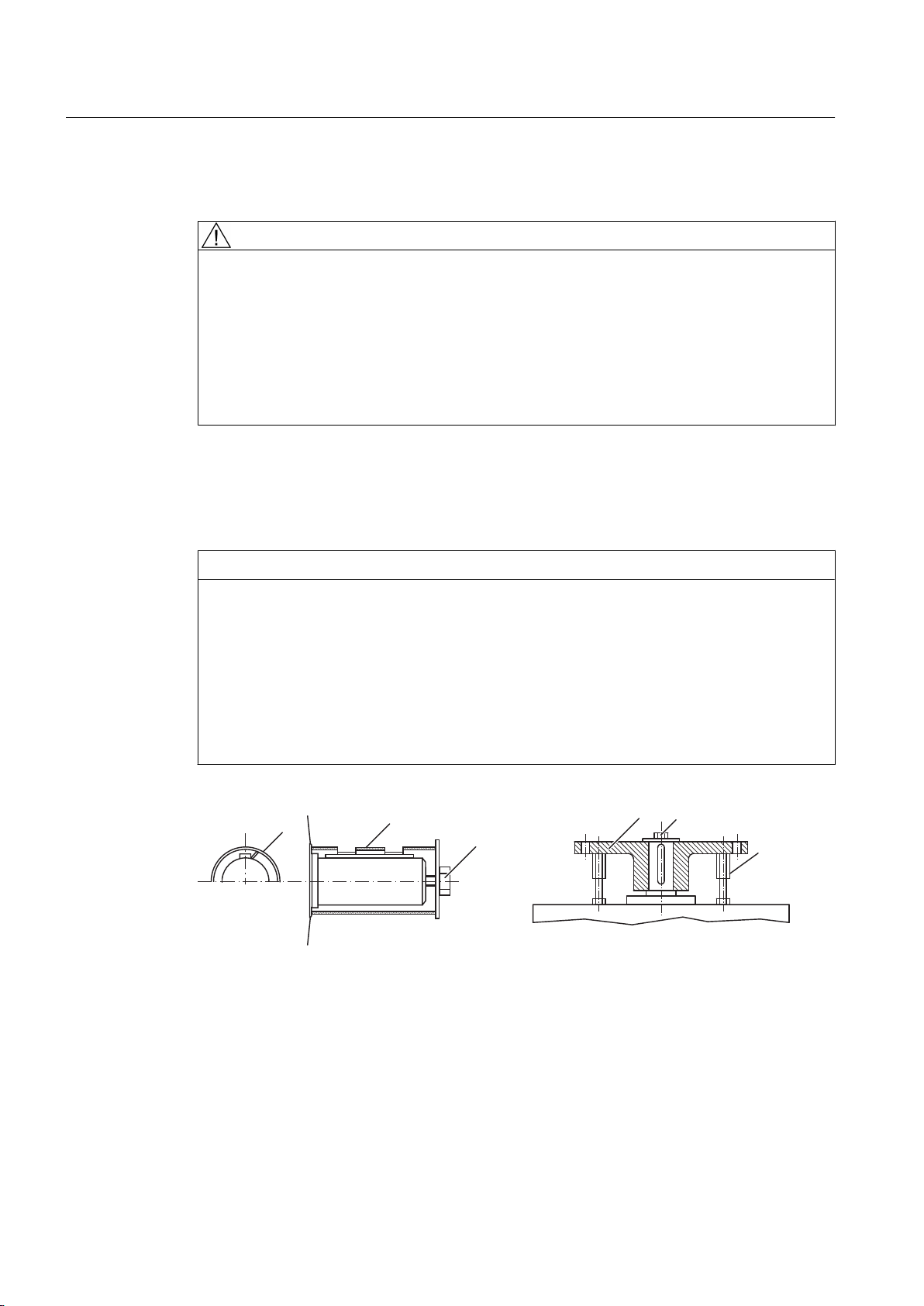
4.7.7 Lifting and transporting the machine
NOTICE
Transport damage if the rotor shipping brace is not used.
The motor can be damaged if it is jolted during transport.
This can result in material damage.
● Always transport the motor with the rotor shipping brace supplied. The rotor shipping brace
must be securely attached during transportation. Do not remove the rotor shipping brace
until you are ready to push on the output element.
● When the motor has to be transported after the output element is pushed on, take other
appropriate measures to fix the axial position of the rotor, see the following figure.
① Sleeve ③ Fixture
② Coupling ④ Shaft screw
Image 4-1 Rotor shipping brace without coupling (1) and with coupling (2).
28 Operating Instructions 02/2016
SIMOTICS DC 1GH5

Preparations for use
4.7 Transport and storage
Table 4-1 Tightening torques for the shaft screw on the rotor shipping brace
Thread in the shaft extension Tightening torque Preload
M20 50 Nm 12 kN
M24 100 Nm 20 kN
M30 180 Nm 32 kN
WARNING
Transporting or lifting the machine
The motor or the motor set may only be transported and lifted with the hoisting lugs, as it
might otherwise tip over or slip out of the lifting equipment. Death, serious injury, or material
damage can result.
● Always use the lugs on the stator frame to lift the motor. Use suitable rope guidance or
spreading devices. You will find the weight of the motor on the rating plate.
● Only lift and transport the motors in a position appropriate to their design.
● Vertical-design motors must always be transported in the vertical position if the rotor is
not fixed. If transport in a horizontal position should prove to be necessary in special cases,
then fix the rotor before bringing the motor the horizontal position. If necessary, vertical
motors with suitable bearings are supplied by the manufacturing plant in the horizontal
position.
Note
Place the machine in a secure and raised position
In order to obtain easy and safe access to the underside of the machine, place it in a secure
and raised position.
DANGER
Standing under suspended loads
If the lifting gear or load handling attachments were to fail, the machine could fall. This can
result in death, serious injury or material damage.
Never remain under or in the immediate vicinity of the machine when it is raised.
SIMOTICS DC 1GH5
Operating Instructions 02/2016 29

Preparations for use
4.7 Transport and storage
4.7.8 Storage
If the machine is not going to be commissioned soon after delivery, ensure that it is stored
correctly.
NOTICE
Seizure damage to bearings
If the machine is stored incorrectly there is a risk that the bearings will suffer damage while
out of use. Examples of resulting damage can include scoring and corrosion.
Read the following storage instructions.
Preconditions and preparations
● Only store goods in undamaged packaging. If goods are delivered in damaged packaging,
unpack them and store appropriately according to the nature of the goods.
● Repair any damage to the packaging before putting the equipment into storage insofar as
this is necessary to ensure proper storage conditions.
General instructions for storage
Wherever possible, store the machine in a storage room. The place of storage must satisfy
the following general conditions:
● Select a sufficiently sized dry and horizontal place of storage that is above flood level and
free of vibration (v
– The place of storage must be well ventilated as well as free of dust and frost. Provide
protection against extreme weather conditions. Ensure that the temperature remains
stable in the range from 10° C (50° F) to 50° C (120° F). The room temperature should
be approx. 10 K above the outside temperature. The temperature should not fall below
‑20° C.
– The relative humidity of the air should be less than 60%.
– The floor of the place of storage must be sufficiently strong. The maximum permissible
floor loading or storage compartment loading may not be exceeded.
– The ambient air must not contain any harmful gases.
● Protect the motor from shocks and humidity.
● Position machines, devices and crates on pallets, wooden beams or foundations that
protect them against rising damp and water.
● Ensure that the air circulation under the equipment is not impeded.
– Place wooden spacer blocks between the covers and the motor.
≤ 0.2 mm/s).
eff
– Covers or tarpaulins must not trail on the floor around the machine.
SIMOTICS DC 1GH5
30 Operating Instructions 02/2016
 Loading...