

Siemens SIMOTICS A-1FV5, SIMOTICS A-1PV5 Operating Instructions Manual

SIMOTICS A-1FV5/1PV5
synchronous/induction motors
___________________
___________________
___________________
___________________
___________________
___________________
___________________
___________________
___________________
___________________
___________________
SIMOTICS A-1FV5/1PV5 synchronous/induction motors
Operating Instructions
03/2014
610.45002.40
Introduction
1
Safety notes
2
Description
3
Preparing for use
4
Mounting
5
Connection
6
Commissioning
7
Operation
8
Service and maintenance
9
Decommissioning and
disposal
10
Appendix
A

Siemens AG
Industry Sector
Postfach 48 48
90026 NÜRNBERG
GERMANY
Order number: 610.45002.40
Ⓟ
Copyright © Siemens AG 2014.
All rights reserved
Legal information
Warning notice system
DANGER
indicates that death or severe personal injury will result if proper precautions are not taken.
WARNING
indicates that death or severe personal injury may result if proper precautions are not taken.
CAUTION
indicates that minor personal injury can result if proper precautions are not taken.
NOTICE
indicates that property damage can result if proper precautions are not taken.
Qualified Personnel
personnel qualified
Proper use of Siemens products
WARNING
Siemens products may only be used for the applications described in the catalog and in the relevant technical
maintenance are required to ensure that the products operate safely and without any problems. The permissible
ambient conditions must be complied with. The information in the relevant documentation must be observed.
Trademarks
Disclaimer of Liability
This manual contains notices you have to observe in order to ensure your personal safety, as well as to prevent
damage to property. The notices referring to your personal safety are highlighted in the manual by a safety alert
symbol, notices referring only to property damage have no safety alert symbol. These notices shown below are
graded according to the degree of danger.
If more than one degree of danger is present, the warning notice representing the highest degree of danger will
be used. A notice warning of injury to persons with a safety alert symbol may also include a warning relating to
property damage.
The product/system described in this documentation may be operated only by
task in accordance with the relevant documentation, in particular its warning notices and safety instructions.
Qualified personnel are those who, based on their training and experience, are capable of identifying risks and
avoiding potential hazards when working with these products/systems.
for the specific
Note the following:
documentation. If products and components from other manufacturers are used, these must be recommended
or approved by Siemens. Proper transport, storage, installation, assembly, commissioning, operation and
All names identified by ® are registered trademarks of Siemens AG. The remaining trademarks in this publication
may be trademarks whose use by third parties for their own purposes could violate the rights of the owner.
We have reviewed the contents of this publication to ensure consistency with the hardware and software
described. Since variance cannot be precluded entirely, we cannot guarantee full consistency. However, the
information in this publication is reviewed regularly and any necessary corrections are included in subsequent
editions.
03/2014 Subject to change

Table of contents
1 Introduction ............................................................................................................................................. 7
2 Safety notes ............................................................................................................................................ 9
3 Description ............................................................................................................................................ 15
4 Preparing for use .................................................................................................................................. 23
5 Mounting ............................................................................................................................................... 29
2.1 General safety information ............................................................................................................. 9
2.2 Safety and operating instructions................................................................................................. 10
2.3 Observing the five safety rules ..................................................................................................... 11
2.4 Thermal hazard ............................................................................................................................ 11
2.5 Information about electromagnetic fields ..................................................................................... 12
2.6 Electrostatic sensitive devices (ESD) .......................................................................................... 13
3.1 Application .................................................................................................................................... 15
3.2 Rating plate (type plate) ............................................................................................................... 16
3.3 Technical features ........................................................................................................................ 17
3.4 Design .......................................................................................................................................... 18
3.4.1 Regulations .................................................................................................................................. 18
3.4.2 Types of construction ................................................................................................................... 18
3.4.3 Degree of protection .................................................................................................................... 18
3.4.4 Ambient conditions ....................................................................................................................... 19
3.4.5 Cooling ......................................................................................................................................... 19
3.4.6 Noise emission ............................................................................................................................. 22
4.1 Shipment and packaging ............................................................................................................. 23
4.2 Transport and storage .................................................................................................................. 23
4.2.1 Transport ...................................................................................................................................... 23
4.2.2 Storage ......................................................................................................................................... 26
5.1 Installation .................................................................................................................................... 29
5.2 Fixing ............................................................................................................................................ 30
5.3 Attaching the output elements ..................................................................................................... 31
5.4 Vibration load ............................................................................................................................... 33
SIMOTICS A-1FV5/1PV5 synchronous/induction motors
Operating Instructions, 03/2014, 610.45002.40
5

Table of contents
6 Connection ........................................................................................................................................... 35
7 Commissioning ..................................................................................................................................... 43
8 Operation .............................................................................................................................................. 49
9 Service and maintenance ...................................................................................................................... 53
10 Decommissioning and disposal ............................................................................................................. 57
A Appendix .............................................................................................................................................. 61
Index .................................................................................................................................................... 65
6.1 Mechanical connection of water cooling system ......................................................................... 35
6.2 Electrical connection ................................................................................................................... 36
6.2.1 Safety information ....................................................................................................................... 36
6.2.2 Cable entry and routing ............................................................................................................... 37
6.2.3 Circuit diagram ............................................................................................................................ 38
6.2.4 Terminal box ............................................................................................................................... 39
6.2.5 Data for electrical connection ...................................................................................................... 40
6.2.6 Signal connection ........................................................................................................................ 41
6.2.7 Connecting the temperature sensor ............................................................................................ 42
6.2.8 Connecting the ground conductor ............................................................................................... 42
6.2.9 Connecting-up a converter .......................................................................................................... 42
7.1 Measures prior to commissioning ............................................................................................... 43
7.2 Performing a trial run ................................................................................................................... 45
7.3 Checking the insulation resistance ............................................................................................. 45
7.4 Switching on the motor ................................................................................................................ 47
7.5 Liquid cooling .............................................................................................................................. 47
8.1 Safety instructions during operation ............................................................................................ 49
8.2 Stoppages ................................................................................................................................... 50
8.3 Shutdown .................................................................................................................................... 50
8.4 Faults ........................................................................................................................................... 50
9.1 Safety information ....................................................................................................................... 53
9.2 Maintenance intervals ................................................................................................................. 55
9.3 General inspection guidelines ..................................................................................................... 56
9.4 Bearing replacement intervals .................................................................................................... 56
10.1 Decommissioning ........................................................................................................................ 57
10.2 Disposal....................................................................................................................................... 57
A.1 List of abbreviations .................................................................................................................... 61
A.2 Siemens Service Center ............................................................................................................. 62
A.3 Declaration of conformity ............................................................................................................ 63
SIMOTICS A-1FV5/1PV5 synchronous/induction motors
6 Operating Instructions, 03/2014, 610.45002.40

1
Note
All data that are generally applicable for the motor also always apply to the generator.
Text format features
Note
A Note is an important item of information about the product, handling of the product
or the relevant section of the document. Notes provide you with help or further
suggestions/ideas.
These operating instructions describe the motor and explain how to handle the motor from
the delivery to the disposal stage.
Before you start using the motor, you must read these operating instructions to ensure safe,
problem-free operation and to maximize the service life.
Siemens strives continually to improve the quality of information provided in these operating
instructions. If you find any mistakes or would like to offer suggestions about how this
document could be improved, please contact the Siemens Service Center.
Always follow the safety instructions and notices in these operating instructions. The warning
notice system is explained on the rear of the inside front.
In addition to the safety-related notices and instructions which you must read, you will find
the text in these operating instructions is formatted in the following way:
1. Handling instructions are always formatted as a numbered list. Always perform the steps
● Lists are formatted as bulletted lists.
in the order given.
– Lists on the second level are hyphenated.
SIMOTICS A-1FV5/1PV5 synchronous/induction motors
Operating Instructions, 03/2014, 610.45002.40
7

Introduction
SIMOTICS A-1FV5/1PV5 synchronous/induction motors
8 Operating Instructions, 03/2014, 610.45002.40
2
2.1
General safety information
Safety and commissioning information for converter-fed low-voltage three-phase motors
DANGER
qualified, responsible personnel
injury or material damage
national, local and plant/system-specific regulations and requirements
Special versions
construction variants
type
designation and serial number
(in accordance with the Low Voltage Directive 2006/95/EC)
All work associated with transporting, connecting, commissioning, and maintaining the
motors must be carried out by
note IEC 60364).
(DIN EN 50110-1;
Failure to follow proper procedures may result in
The valid
carefully observed.
aspects. If in doubt, you are strongly advised to contact the manufacturer specifying the
carried out by the SIEMENS Service Center.
Vehicles with converter-fed low-voltage three-phase motors must fulfill the protective
requirements of the EMC Directive 2004/108/EC.
The user is responsible for ensuring that installation is carried out properly. The signal and
power cables must be shielded.
The information provided by the converter manufacturer regarding EMC-compliant
installation must be observed.
and
may differ with respect to certain technical
(see rating plate) or arrange for any maintenance work to be
.
must be
SIMOTICS A-1FV5/1PV5 synchronous/induction motors
Operating Instructions, 03/2014, 610.45002.40
9
Safety notes
2.2
Safety and operating instructions
The safe use of electrical machines
WARNING
Rotating or live parts
Qualified personnel
Note
Siemens Service Center
We recommend engaging the support and services of your local Siemens Service Center
for all planning, installation, commissioning, and maintenance work.
2.2 Safety and operating instructions
Rotating or live parts are dangerous.
Fatal or severe injuries and substantial material damage can occur if the required covers
are removed or if the machines are not handled, operated, or maintained properly.
Covers must only be removed and the motor operated in accordance with the relevant
regulations. The motor must be maintained on a regular basis.
These operating instructions only contain the information necessary for ensuring that the
motor is operated by properly trained personnel in accordance with its intended purpose.
Those responsible for plant safety must ensure the following:
● The basic planning work for the system and all work relating to transportation, assembly,
installation, commissioning, maintenance and repairs is carried out by qualified personnel
and checked by responsible, suitably skilled personnel.
● The operating instructions and the motor documentation are available at all times.
● The technical data and specifications relating to installation, connection, ambient and
operating conditions are taken into account at all times.
● The system-specific installation and safety regulations are observed.
● Personal protective equipment is used.
● Unqualified persons must not work on or in the vicinity of these motors at any time.
SIMOTICS A-1FV5/1PV5 synchronous/induction motors
10 Operating Instructions, 03/2014, 610.45002.40
Safety notes
2.3
Observing the five safety rules
Five safety rules
2.4
Thermal hazard
CAUTION
Do not touch any hot surfaces!
Only operate the motors in conjunction with effective temperature control.
2.3 Observing the five safety rules
For your personal safety and to prevent material damage when working on the machine,
always observe the safety instructions and the following five safety rules. Apply the five
safety rules in the order stated before starting work at the machine.
1. Disconnect the system.
You must also make sure that the auxiliary circuits are also disconnected.
2. Protect against reconnection.
3. Make sure that the equipment is de-energized.
4. Ground and short-circuit.
5. Cover or enclose adjacent components that are still live.
When work has been completed, remove these measures in reverse order.
The surface temperature of the motors can exceed 65 °C.
Temperature-sensitive components (electric cables, electronic components) must not be
placed on hot surfaces. If the motors overheat, this can destroy the windings/bearings and
the permanent magnet may become demagnetized
SIMOTICS A-1FV5/1PV5 synchronous/induction motors
Operating Instructions, 03/2014, 610.45002.40
11
Safety notes
2.5
Information about electromagnetic fields
Note
Permanent magnets
The rotors of 1FV5 synchronous motors contain permanent magnets with high magnetic flux
densities and strong forces of attraction to ferromagnetic bodies.
Persons with cardiac pacemakers are endangered in the vicinity of a disassembled rotor.
Data stored o
WARNING
Electromagnetic fields
2.5 Information about electromagnetic fields
n electronic data carriers can be destroyed.
Electromagnetic fields are generated when electrical power engineering installations
(e.g. transformers, converters, or motors) are operated.
Electromagnetic fields can interfere with electronic devices, which could cause them to
malfunction. Heart pacemakers can be affected, for example, which could potentially
damage a person's health or even result in death. Steps must be taken, therefore, to
ensure that persons with heart pacemakers cannot enter these areas.
The plant operator is responsible for taking appropriate measures (labels and hazard
warnings) to adequately protect operating personnel and others against any possible risk.
● Observe the relevant nationally applicable health and safety regulations. In Germany,
"electromagnetic fields" are subject to regulations BGV B11 and BGR B11 stipulated by
the German statutory industrial accident insurance institution.
● Display adequate hazard warning notices.
● Place barriers around hazardous areas.
● Take appropriate measures (e.g. shields) to reduce electromagnetic fields at their source.
SIMOTICS A-1FV5/1PV5 synchronous/induction motors
12 Operating Instructions, 03/2014, 610.45002.40
Safety notes
2.6
Electrostatic sensitive devices (ESD)
ESD guidelines
NOTICE
Electrostatic discharge
NOTICE
Use conductive packaging material
2.6 Electrostatic sensitive devices (ESD)
Electronic modules contain components that can be destroyed by electrostatic discharge.
These modules can be easily destroyed by improper handling.
To protect your equipment against damage, follow the instructions given below.
● Never touch electronic modules unless absolutely necessary in the course of
maintenance and repair procedures.
● If the modules have to be touched, the body of the person concerned must be
electrostatically discharged immediately beforehand and be grounded.
● Electronic modules should not come into contact with electrically insulating materials
(e.g. plastic foil, plastic parts, insulating table supports, or clothing made of synthetic
fibers).
● Always place the modules on conductive bases.
● Always store and transport electronic modules or components in conductive packaging
(e.g. metallized plastic or metal containers).
Electronic modules must be stored, transported, and dispatched in conductive
packaging.
Electronic modules that are not correctly stored, transported, or dispatched can be
damaged.
Pack electronic modules in appropriate conductive packaging (e.g. foam rubber or
aluminum foil).
SIMOTICS A-1FV5/1PV5 synchronous/induction motors
Operating Instructions, 03/2014, 610.45002.40
13

Safety notes
(1)
Sitting
(2)
Standing
(3)
Standing/sitting
ESD protective measures
a
= conductive floor
b
= ESD table
c
= ESD footwear
d
= ESD coat
s
= ESD wrist strap
f
= cubicle ground connection
2.6 Electrostatic sensitive devices (ESD)
The necessary ESD protective measures for electrostatically sensitive devices are illustrated
once again in the following drawings:
Figure 2-1 ESD protective measures
SIMOTICS A-1FV5/1PV5 synchronous/induction motors
14 Operating Instructions, 03/2014, 610.45002.40

3
3.1
Application
Proper usage
Mode of operation and design
The motors are designed for installation in electrically driven vehicles. and are characterized
by their high power density, ruggedness, long lifetime, and overall reliability. The three-phase
motors are either closed-loop speed or torque controlled using a converter. The direct
connection to the three-phase line supply is not permissible. It is forbidden to install them in
hazardous areas unless they are explicitly designed for this.
The 1PV5 motors are liquid-cooled squirrel-cage induction motors.
The 1FV5 generators are liquid-cooled synchronous motors with permanent magnet rotors.
Both active parts are equipped with two temperature sensors integrated in the stator winding,
where the second can be used as a reserve.
An encoder system for sensing the speed and direction of rotation is optionally installed in
the NDE bearing shield of the motors.
SIMOTICS A-1FV5/1PV5 synchronous/induction motors
Operating Instructions, 03/2014, 610.45002.40
15
Description
3.2
Rating plate (type plate)
No.
Description
No.
Description
L010
MLFB
L170
Rated power PN (3)
L020
Factory serial number
L180
Unit rated power (3)
L025
Consecutive number
L190
Rated current IN (3)
L040
Options
L210
Rated speed nN (3)
L060
Maximum speed n
L230
Temperature class
L070
Operating mode (1)
L240
Degree of protection
L071
Rated time (1)
L250
Type of construction
L072
Unit rated time (1)
L260
Revision number
L080
Rated power PN (1)
L270
Weight
L090
Rated current IN (1)
L280
Temperature sensor
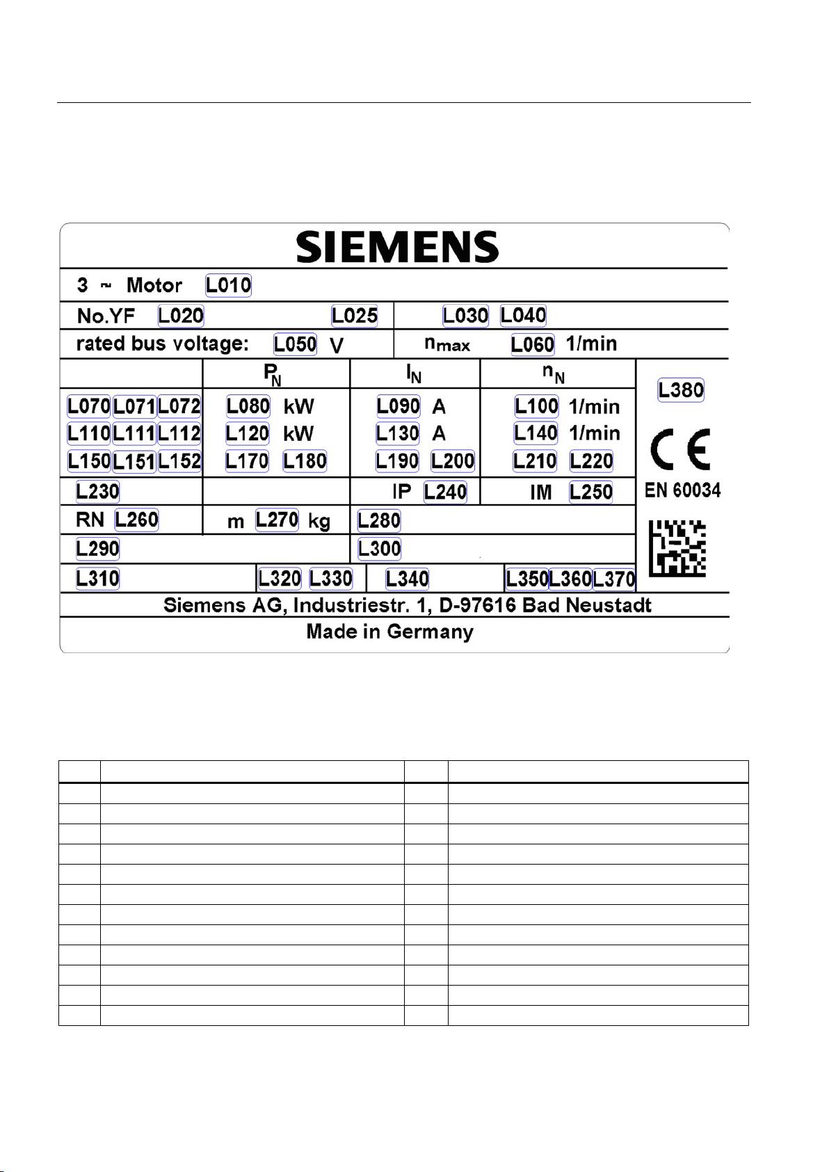
3.2 Rating plate (type plate)
The rating plate (type plate) shows the technical specifications for the supplied motor.
Figure 3-1 Schematic layout of rating plate
Table 3- 1 Elements on the rating plate
L030 Z: (For options) L200 Unit rated current IN (3)
L050 Rated voltage L220 Rated speed nN (3)
max
SIMOTICS A-1FV5/1PV5 synchronous/induction motors
16 Operating Instructions, 03/2014, 610.45002.40
Description
No.
Description
No.
Description
L100
Rated speed nN (1)
L290
Encoder (encoder)
L110
Operating mode (2)
L300
Optional customer information
L111
Rated time (2)
L310
Cooling method
L112
Unit rated time (2)
L320
Coolant flow
L120
Rated power PN (2)
L330
Unit coolant flow
L130
Rated current IN (2)
L340
Cooling pressure
L140
Rated speed nN(2)
L350
Maximum value
L150
Operating mode (3)
L360
Maximum coolant temperature
L151
Rated time (3)
L370
Unit maximum coolant temperature
L152
Unit rated time (3)
L380
UL mark
3.3
Technical features
1FV5
1PV5
synchronous motor
Magnet material
Rare-earth magnetic material
---
Speed encoder (optional)
Rotor position encoder (RPE)
Toothed-wheel encoder (64 pin)
Insulation of stator winding according to EN 60034–1
Thermal class 180 (H)
Cooling
Liquid cooling
Installation altitude according to EN 60034-1
≤ 2500 m above sea level, otherwise power derating
Degree of protection to EN60034-5
IP65/IP69K (without DE shaft output)
EN 60034-11
(half-key balancing)
in accordance with DIN 42955
Vibration severity grade according to EN 60034-14
Grade A is maintained up to rated speed
Sound pressure level according to DIN EN ISO 1680
75 dB (A) + 3 dB (A) tolerance
12-pin signal connector
3.3 Technical features
Table 3- 2 Technical features
Type of motor Permanent-magnet
Type of construction acc. to EN 60034–7 IM B5
Temperature monitoring in accordance with
DE shaft extension accordance with DIN 748-3 Plain or geared shaft, optional shaft with fitted key and keyway
Radial eccentricity, concentricity and axial eccentricity
Connection Terminal board in the terminal box for power
2 x KTY 84-130 temperature sensor in the stator winding
Tolerance N (normal)
Induction motor
SIMOTICS A-1FV5/1PV5 synchronous/induction motors
Operating Instructions, 03/2014, 610.45002.40
17
Description
3.4
Design
3.4.1
Regulations
Feature
Standard
Rated and operation characteristics
IEC/EN 60034-1
Degree of protection
IEC/EN 60034-5
Cooling
IEC/EN 60034-6
Type of construction
IEC/EN 60034-7
Terminal markings
IEC/EN 60034-8
Noise emission
IEC/EN 60034-9
Temperature monitoring
IEC/EN 60034-11
Vibration severity grades
IEC/EN 60034-14
(1)
The degree of protection and type of construction of the motor are stamped on its rating plate.
Note
Make sure that your end product is in compliance with all of the applicable legislation!
You
and requirements.
3.4.2
Types of construction
3.4.3
Degree of protection
3.4 Design
The motors comply with the following regulations according to IEC 60034-x/EN 60034-x:
Table 3- 3 Regulations that have been applied
(1)
(1)
The three-phase motors comply with the relevant sections of EN 60034 and EN 60204-1.
Three-phase motors comply with Low-Voltage Directive 2006/95/EC. Standard motors
comply with the UL regulations. "UR" is stamped on the rating plate of these motors.
must take into account the applicable national, local, and system-specific regulations
The motor has type construction IM B5.
The motors have degree of protection IP65/IP69K. In order to guarantee the degree of
protection, the drive end flange must be suitably implemented.
SIMOTICS A-1FV5/1PV5 synchronous/induction motors
18 Operating Instructions, 03/2014, 610.45002.40
Description
3.4.4
Ambient conditions
3.4.5
Cooling
Water cooling
Coolant
Water/anti-freeze mixture, 50/50 %
Female thread in the bearing shield Pg 13.5 /8 deep
Lower values will result in a derating
Max. pressure at inlet
max. 2.5 bar
< 0.4 bar for minimum cooling water flow with 1FV516
at T
<60 °C; T
> -40 °C
temperature, without derating
higher values will result in derating
3.4 Design
The motors are designed for ambient temperatures from -40 °C to +70 °C and installation
altitudes up to 2500 m above sea level. In the case of different ambient conditions, contact
the manufacturer.
The motor can only be operated in a closed coolant circuit with a cooling unit. The motor is
connected to the cooling circuit using two hose connections with an outer diameter of 18 mm
at the NDE bearing shield of the motor. On motors with angled hose connections, after
loosening the locknuts they can be adjusted in both directions (preferred direction clockwise;
max. 1 revolution). After adjusting the position, the coolant connections must be fixed by
tightening the union nuts.
The inlet and outlet connections can be selected as required.
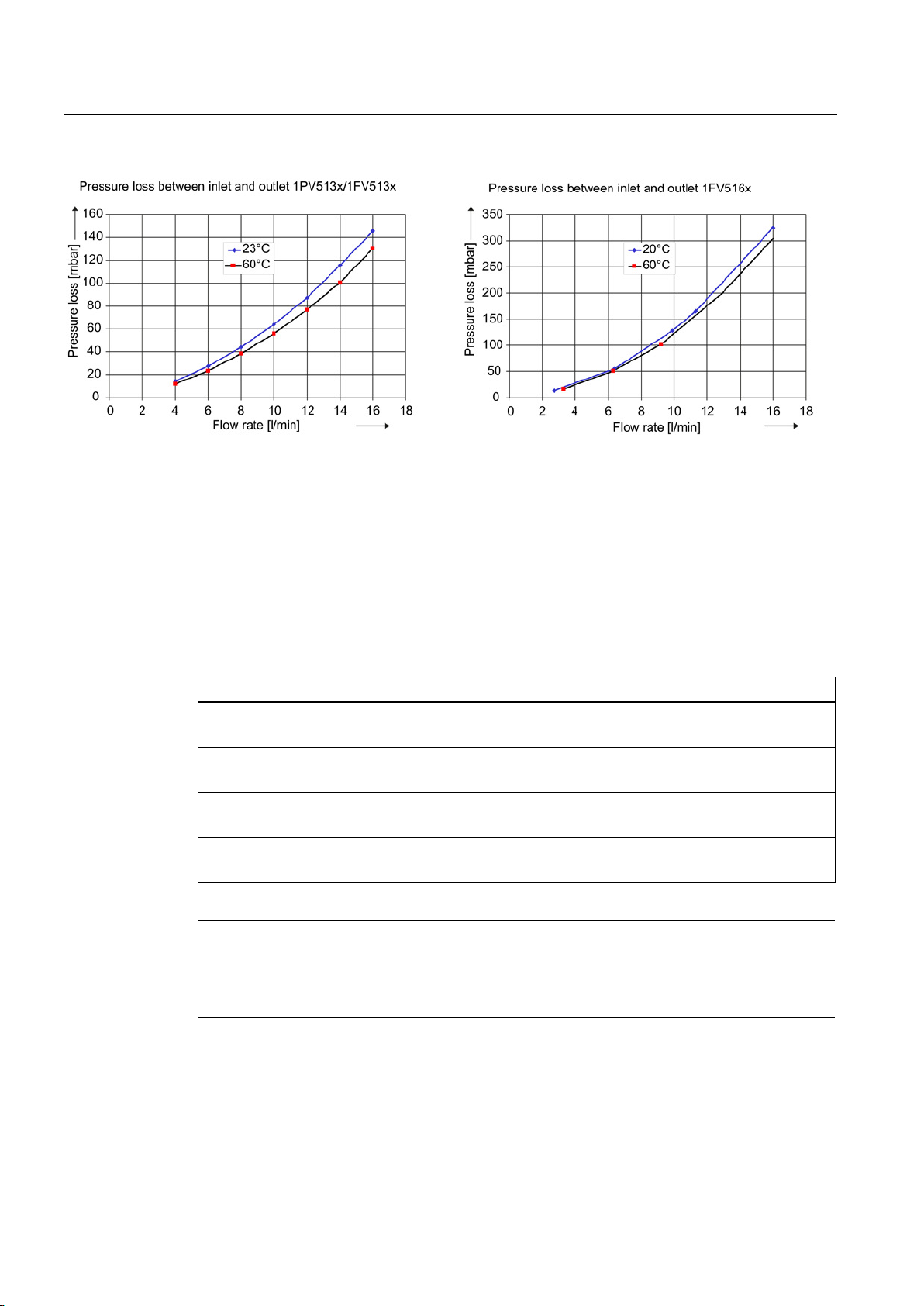
Table 3- 4 Technical data of the water cooling
Cooling water connection Hose connection with an outer diameter of 18
Cooling water flow 16 l/min
Pressure loss between inlet and
outlet
Min. cooling water inlet temperature T
Maximum cooling water inlet
< 0.2 bar for minimum cooling water flow with
1PV513/1FV513
> T
cool
ambient
≤ 55 °C,
ambient
– 5 K
coolmin
As coolant, only a water/anti-freeze mixture in a ratio of 50 % / 50 % is permissible. Glycol is
recommended as antifreeze. When you select a different anti-freeze, a minimum steadystate temperature of -40 °C must be observed. Different anti-freeze agents should not be
mixed.
A filter (100 µm) must be installed in the inlet pipe to protect the motor against pollution.
Additional protection for the motor must be provided by means of a pressure relief valve
installed downstream from the filter.
If a throttle is needed to restrict the flow, it is best to install it downstream of the motor. It is
not permissible to install the throttle directly in front of the inlet because the effects of
cavitation may damage the motor.
SIMOTICS A-1FV5/1PV5 synchronous/induction motors
Operating Instructions, 03/2014, 610.45002.40
19
Description
Contents and chemical composition
Value
pH value
6 … 8
Sulfate ions
< 50 ppm
Dissolved solids
< 340 ppm
Total hardness
< 170 ppm
Electrical conductivity
< 500 μS/cm
Size of any particles in the coolant
< 100 µm
Note
Storing or transporting the motor
The cooling circuit must be emptied when storing the motor, for longer periods when the
motor is out of service and when the motor is being transported.
3.4 Design
Figure 3-2 Pressure losses as a result of volumetric flow
Coolant temperatures below the ambient temperature lead to increased condensation of
water. The difference between the coolant inlet temperature and ambient temperature should
therefore not exceed maximum 5 Kelvin. If the motor is out of operation for a prolonged
period of time, coolant inflow must additionally be interrupted.
The values specified for the cooling water (refer to the following table) correspond to the
requirements of closed cooling circuits. Not all of the specified concentrations will occur in
the cooling water at the same time.
Table 3- 5 Water specifications for the coolant
Chloride ions < 40 ppm
Nitrate ions < 50 ppm
SIMOTICS A-1FV5/1PV5 synchronous/induction motors
20 Operating Instructions, 03/2014, 610.45002.40
 Loading...