

Siemens SIMOREG DC Master 6RA7028-6DS22, SIMOREG DC Master 6RA7078-6DS22, SIMOREG DC Master 6RA7025-6DS22, SIMOREG DC Master 6RA7085-6DS22, SIMOREG DC Master 6RA7087-6DS22 Operating Instructions Manual
...
SIMOREG DC Master
6RA70 Series
Operating Instructions
Microprocessor-Based Converters from 6kW to 1900kW
for Variable-Speed DC Drives
Edition 06 Order-No.: 6RX1700-0AD76

General 02.00
© Siemens AG 1998 All rights reserved
These Operating Insructions are available in the following languages:
Language German French Spanish Italian
Order No. 6RX1700-0AD00 6RX1700-0AD77 6RX1700-0AD78 6RX1700-0AD72
Converter software version:
As these Operating Instructions went to print, SIMOREG DC Master converters were being delivered from the
factory with software version 1.8 installed.
These Operating Instructions also apply to other software versions.
Earlier software versions: Some parameters described in this document might not be stored in the software
(i.e. the corresponding functionality is not available on the converter) or some
parameters will have a restricted setting range. If this is the case, however,
appropriate reference to this status will be made in the Parameter List.
Later software versions: Additional parameters might be available on the SIMOREG DC Master (i.e. extra
functions might be available which are not described in these Operating
Instructions) or some parameters might have an extended setting range. In this
case, leave the relevant parameters at their factory setting, or do not set any
parameter values which are not described in these Instructions !
The latest software version is available at the following Internet site:
http://www.siemens.at/eww/a&d/updates (password for access: "simo1reg”).
The reproduction, transmission or use of this document or contents is
not permitted without express written authority. Of f enders will be liable
for damages. All right s, including rights created by patent grant or
registration of a utility model or design, are reserved.
We have checked that the contents of this publ i cation agree with the
hardware and software described herein. Nonetheless, di fferences
might exist and therefore we cannot guarantee t hat they are completely
identical. The information given in this publication i s reviewed at regular
intervals and any corrections t hat might be necessary are made in the
subsequent printings. Suggestions for improvem ent are welcome at all
times.
SIMOREG ® is a registered trademark of Siemens

02.00 Contents
Siemens AG 6RX1700-0AD76 0-1
SIMOREG DC Master Operating Instrc tions
0 Contents
Page
1 Safety information
2 Type spectrum
2.1 Converter order number code 2-4
2.2 Ordering information for options using codes 2-5
3 Description
3.1 Applications 3-1
3.2 Design 3-1
3.2.1 Special features of devices with 460V rated connection voltage 3-2
3.3 Mode of operation 3-2
3.4 Technical data 3-3
3.4.1 Load types 3-3
3.4.1.1 Load cycles for 1Q applications 3-4
3.4.1.2 Load cycles for 4Q applications 3-5
3.4.2 Converters 3AC 400V, 30A to 125A, 1Q 3-7
3.4.3 Converters 3AC 400V, 210A to 600A, 1Q 3-8
3.4.4 Converters 3AC 400V, 850A to 2000A, 1Q 3-9
3.4.5 Converters 3AC 460V, 30A to 125A, 1Q 3-10
3.4.6 Converters 3AC 460V, 210A to 600A, 1Q 3-11
3.4.7 Converters 3AC 460V, 850A to 1200A, 1Q 3-12
3.4.8 Converters 3AC 575V, 60A to 600A, 1Q 3-13
3.4.9 Converters 3AC 575V, 800A to 2000A, 1Q 3-14
3.4.10 Converters 3AC 690V, 720A to 2000A, 1Q 3-15
3.4.11 Converters 3AC 830V, 900A to 1900A, 1Q 3-16
3.4.12 Converters 3AC 400V, 15A to 125A, 4Q 3-17
3.4.13 Converters 3AC 400V, 210A to 600A, 4Q 3-18
3.4.14 Converters 3AC 400V, 850A to 2000A, 4Q 3-19
3.4.15 Converters 3AC 460V, 30A to 125A, 4Q 3-20
3.4.16 Converters 3AC 460V, 210A to 600A, 4Q 3-21
3.4.17 Converters 3AC 460V, 850A to 1200A, 4Q 3-22
3.4.18 Converters 3AC 575V, 60A to 600A, 4Q 3-23
3.4.19 Converters 3AC 575V, 850A to 2000A, 4Q 3-24
3.4.20 Converters 3AC 690V, 760A to 2000A, 4Q 3-25
3.4.21 Converters 3AC 690V, 950A to 1900A, 4Q 3-26
3.5 Applicable standards 3-28
3.6 Abbreviations 3-28

Contents 02.00
0-2 Siemens AG 6RX1700-0AD76
SIMOREG DC Master Operating Instrc tions
Page
4 Shipment, unpacking
4.1 Remove the transportation protection for devices with 1500A to 2000A rated DC 4-1
5 Installation
5.1 Dimension diagrams for standard devices 5-3
5.1.1 Converters: 30A, 1Q 5-3
5.1.2 Converters: 60A to 280A, 1Q 5-4
5.1.3 Converters: 400A, 1Q 5-5
5.1.4 Converters: 600A, 1Q 5-6
5.1.5 Converters: 720A to 850A, 1Q 5-7
5.1.6 Converters: 900A to 1200A, 1Q 5-8
5.1.7 Converters: 1500A to 2000A, 1Q 5-9
5.1.8 Converters: 15A to 30A, 4Q 5-10
5.1.9 Converters: 60A to 280A, 4Q 5-11
5.1.10 Converters: 400A to 600A, 4Q 5-12
5.1.11 Converters: 760A to 850A, 4Q 5-13
5.1.12 Converters: 950A to 1200A, 4Q 5-14
5.1.13 Converters: 1500A to 2000A, 4Q 5-15
5.2 Dimension diagrams of the devices with additional cable connections
on the top of the device 5-16
5.2.1 Converters: 60A to 125A, 1Q 5-16
5.2.2 Converters: 210A to 280A, 1Q 5-17
5.2.3 Converters: 450A to 600A, 1Q 5-18
5.2.4 Converters: 850A, 1Q 5-19
5.2.5 Converters: 60A to 125A, 4Q 5-20
5.2.6 Converters: 210A to 280A, 4Q 5-21
5.2.7 Converters: 450A to 600A, 4Q 5-22
5.2.8 Converters: 850A, 4Q 5-23
5.3 Mounting options 5-24
5.3.1 Terminal expansion board CUD2 5-24
5.3.2 Optional supplementary boards 5-25
5.3.2.1 Local bus adapter (LBA) for mounting optional supplementary boards 5-25
5.3.2.2 Mounting of optional supplementary boards 5-26

02.00 Contents
Siemens AG 6RX1700-0AD76 0-3
SIMOREG DC Master Operating Instrc tions
Page
6 Connections
6.1 Installation instructions for proper EMC installation of drives 6-2
6.1.1 Fundamental principles of EMC 6-2
6.1.1.1 What is EMC 6-2
6.1.1.2 Noise radiation and noise immunity 6-2
6.1.1.3 Limit values 6-2
6.1.1.4 SIMOREG converters in industrial applications 6-3
6.1.1.5 Non-grounded supply systems 6-3
6.1.1.6 EMC planning 6-3
6.1.2 Proper EMC installation of drives (installation instructions) 6-4
6.1.2.1 General 6-4
6.1.2.2 Rules for proper EMC installation 6-4
6.1.2.3 Converter component arrangement 6-13
6.1.2.4 List of the recommended radio interference suppression filters 6-14
6.1.3 Information on line-side harmonics generated by converters in a
fully-controlled three-phase bridge circuit configuration 6-15
6.2 Block diagrams with recommended connection 6-17
6.3 Parallel connection of converters 6-18
6.3.1 Circuit diagram showing parallel connection of SIMOREG converters 6-18
6.3.2 Parameterization of SIMOREG converters for parallel connection 6-19
6.3.2.1 Standard operating mode 6-19
6.3.2.2 Operating mode "N+1 mode" (redundancy mode) 6-20
6.4 Power connections 6-22
6.4.1 Converters: 30A, 1Q 6-22
6.4.2 Converters: 60A, 1Q 6-23
6.4.3 Converters: 90A to 280A, 1Q 6-24
6.4.4 Converters: 400A to 600A, 1Q 6-25
6.4.5 Converters: 720A, 1Q 6-26
6.4.6 Converters: 800 to 850A, 1Q 6-27
6.4.7 Converters: 900A to 950A, 1Q 6-28
6.4.8 Converters: 1000 to 1200A, 1Q 6-29
6.4.9 Converters: 1500 to 2000A, 1Q 6-30
6.4.10 Converters: 15 to 30A, 4Q 6-32
6.4.11 Converters: 60A, 4Q 6-33
6.4.12 Converters: 90A to 210A, 4Q 6-34
6.4.13 Converters: 280A, 4Q 6-35
6.4.14 Converters: 400A, 4Q 6-36
6.4.15 Converters: 450A to 600A, 4Q 6-37
6.4.16 Converters: 760A, 4Q 6-38
6.4.17 Converters: 850A, 4Q 6-39

Contents 02.00
0-4 Siemens AG 6RX1700-0AD76
SIMOREG DC Master Operating Instrc tions
Page
6.4.18 Converters: 950A to 1000A, 4Q 6-40
6.4.19 Converters: 1100 to 1200A, 4Q 6-41
6.4.20 Converters: 1500 to 2000A, 4Q 6-42
6.5 Field supply 6-44
6.6 Fuses and commutating reactors 6-47
6.6.1 Commutating reactors 6-47
6.6.2 Fuses 6-47
6.6.2.1 Recommended fuses for field circuit 6-47
6.6.2.2 Fuses for armature circuit 6-47
6.6.2.2.1 Converters 1Q: 400V, 575V, 690V and 830V 6-47
6.6.2.2.2 Converters 1Q: 460V 6-48
6.6.2.2.3 Converters 4Q: 400V, 575V, 690V and 830V 6-49
6.6.2.2.4 Converters 4Q: 460V 6-50
6.6.2.3 F1 and F2 fuses in the power interface 6-50
6.7 Terminal arrangement 6-51
6.8 Terminal assignments 6-54
7 Start-up
7.1 General safety information 7-1
7.2 Operator control panels 7-3
7.2.1 Simple operator control panel (PMU) 7-3
7.2.2 User-friendly operator control panel (OP1S) 7-4
7.3 Parameterization procedure 7-6
7.3.1 Parameter types 7-6
7.3.2 Parameteratization on simple operator control panel 7-6
7.4 Reset to default value and adjust offset 7-8
7.5 Start-up procedure 7-9
7.6 Manual optimization (if necessary) 7-17
7.6.1 Manual setting of armature resistance R
A
(P110) and
armature inductance L
A
(P111) 7-17
7.6.2 Manual setting of field resistance R
F
(P112) 7-18
7.7 Starting up optional supplementary boards 7-19
7.7.1 Procedure for starting up technology boards (T100, T300, T400) 7-19
7.7.2 Sequence of operations for starting up PROFIBUS boards (CB1, CBP, CBP2) 7-20
7.7.3 Sequence of operations for starting up CAN bus boards (CB2, CBC) 7-27
7.7.4 Procedure for starting up SIMOLINK boards (SLB) 7-33
7.7.5 Procedure for staring up expansion boards (EB1 and EB2) 7-36
7.7.6 Procedure for starting up the pulse encoder board (SBP) 7-37
8 Function diagrams

02.00 Contents
Siemens AG 6RX1700-0AD76 0-5
SIMOREG DC Master Operating Instrc tions
Page
9 Function descriptions
9.1 General explanations of terms and functionality 9-1
9.2 Computation cycles, time dela 9-5
9.3 Switch-on, shutdown, enabling 9-6
9.3.1 OFF2 (voltage disconnection) - control word 1, bit 1 9-6
9.3.2 OFF3 (Fast stop) - control word 1, bit 2 9-6
9.3.3 Switch-on / shutdown (ON / OFF) terminal 37 - control word 1, bit 0 9-7
9.3.4 Operating enable (enable) terminal 38 - control word 1, bit 3 9-10
9.4 Ramp-function generator 9-10
9.4.1 Definitions 9-11
9.4.2 Operating principle of ramp-function generator 9-11
9.4.3 Control signals for ramp-function generator 9-12
9.4.4 Ramp-function generator settings 1, 2 and 3 9-12
9.4.5 Ramp-up integrator 9-13
9.4.6 Ramp-function generator tracking 9-13
9.4.7 Limitation after ramp-function generator 9-14
9.4.8 Velocity signal dv/dt (K0191) 9-14
9.5 Inching 9-14
9.6 Crawling 9-15
9.7 Fixed setpoint 9-15
9.8 Safety shutdown (E-Stop) 9-16
9.9 Activation command for holding or operating brake (low active) 9-17
9.10 Switch on auxiliaries 9-20
9.11 Switch over parameter sets 9-20
9.12 Speed controller 9-21
9.13 Serial interfaces 9-22
9.13.1 Serial interfaces with USS
®
protocol 9-23
9.13.2 Serial interfaces with peer-to-peer protocol 9-25
9.14 Thermal overload protection of DC motor
(I
2
t monitoring of motor) 9-29
9.15 Dynamic overload capability of power section 9-32
9.15.1 Overview of functions 9-32
9.15.2 Configuring for dynamic overload capability 9-33
9.15.3 Characteristics for determining the dynamic overload capability
for intermittent overload operation 9-35
9.16 Speed-dependent current limitation 9-65
9.16.1 Setting the speed-dependent current limitation for motors
with commutation transition 9-66
9.16.2 Setting of speed-dependent current limitation for motors
without commutation transition 9-67
9.17 Automatic restart 9-68

Contents 02.00
0-6 Siemens AG 6RX1700-0AD76
SIMOREG DC Master Operating Instrc tions
Page
9.18 Field reversal 9-68
9.18.1 Direction of rotation reversal using field reversal 9-69
9.18.2 Braking with field reversal 9-70
9.19 Status description of some bits of status word ZSW1 9-72
10 Faults / Alarms
10.1 Fault messages 10-1
10.1.1 General information about faults 10-1
10.1.2 List of fault messages 10-2
10.1.2.1 Supply faults 10-2
10.1.2.2 Interface error 10-5
10.1.2.3 External faults 10-7
10.1.2.4 Fault messages from motor sensors 10-8
10.1.2.5 Drive faults 10-8
10.1.2.6 External faults 10-9
10.1.2.7 Drive faults 10-9
10.1.2.8 Start-up faults 10-12
10.1.2.9 External faults 10-17
10.1.2.10 Start-up faults 10-17
10.1.2.11 Hardware faults 10-18
10.1.2.12 Internal faults 10-19
10.1.2.13 Communication errors with supplementary boards 10-22
10.1.2.14 Faults messages from supplementary boards 10-23
10.2 Alarms 10-24
11 Parameter list
12 List of connectors and binectors
12.1 Connector list 12-1
12.2 Binector list 12-22
13 Maintenance
13.1 Procedure for updating software (upgrading to a new software version) 13-2
13.2 Replacement of components 13-3
13.2.1 Replacement of fan 13-3
13.2.2 Replacement of PCBs 13-6
13.2.3 Replacement of thyristor modules on converters up to 1200A 13-7
13.2.4 Replacement of fuses and thyristor assemblies on converters of 1500A and above 13-8

02.00 Contents
Siemens AG 6RX1700-0AD76 0-7
SIMOREG DC Master Operating Instrc tions
Page
14 Servicing / Spare parts
14.1 Servicing 14-1
14.1.1 Europe 14-1
14.1.2 USA 14-2
14.2 Spare parts 14-2
15 SIMOVIS
15.1 Scope of supply 15-1
15.2 Installation of software 15-1
15.3 Connection of SIMOREG converter to PC 15-1
15.4 Further information 15-2
16 Environmental compatibility
17 Applications
18 Appendix
18.1 Additional documentation 18-1
Sheet for customer feedback 18-3

Contents 02.00
0-8 Siemens AG 6RX1700-0AD76
SIMOREG DC Master Operating Instrc tions
02.00 Safety Information
SIEMENS AG 6RX1700-0AD76 1-1
SIMOREG DC Master Operating Instruc tions
1 Safety information
WARNING
Hazardous voltages and rotating parts (fans) are present in this electrical equipment during
operation. Non-observance of the safety instructions can result in death, severe personal injury
or substantial property damage.
Only qualified personnel should work on or around the equipment after first becoming
thoroughly familiar with all warning and safety notices and maintenance procedures contained
herein. The successful and safe operation of this equipment is dependent on proper handling,
installation, operation and maintenance.
Definitions:
• QUALIFIED PERSONNEL
For the purpose of this Instruction Manual and product labels, a "Qualified person" is someone
who is familiar with the installation, construction and operation of the equipment and the hazards
involved. He or she must have the following qualifications:
1. Trained and authorized to energize, de-energize, clear, ground and tag circuits and
equipment in accordance with established safety procedures.
2. Trained in the proper care and use of protective equipment in accordance with established
safety procedures.
3. Trained in rendering first aid.
• DANGER
For the purpose of this Instruction Manual and product labels, "Danger" indicates that death,
severe personal injury or substantial property damage will result if proper precautions are not
taken.
• WARNING
For the purpose of this Instruction Manual and product labels, "Warning" indicates that death,
severe personal injury or substantial property damage can result if proper precautions are not
taken.
• CAUTION
For the purpose of this Instruction Manual and product labels, "Caution" indicates that minor
personal injury or property damage can result if proper precautions are not taken.
• NOTE
For the purpose of this Instruction Manual, "Note" indicates information about the product or the
respective part of the Instruction Manual which requires particular attention.
Safety Information 02.00
1-2 SIEMENS AG 6RX1700-0AD76
SIMOREG DC Master Operating Instrc tions
NOTE
These operating instructions do not purport to cover all details or variations in equipment, nor to
provide for every possible contingency to be met in connection with installation, operation or
maintenance.
Should further information be desired or should particular problems arise which are not covered
sufficiently for the purchaser’s purposes, the matter should be referred to the local Siemens
Sales Office.
The contents of these operating instructions shall not become part or modify any prior or existing
agreement, commitment or relationship. The Sales Contract contains the entire obligations of
Siemens. The warranty contained in the contract between the parties is the sole warranty of
Siemens. Any statements contained herein do not create new warranties or modify the existing
warranty.
DANGER
Converters contain hazardous electrical voltages, Death, severe bodily injury or significant
material damage can occur if the safety measures are not followed.
1. Only qualified personnel, who are knowledgeable about the converters and the provided
information, can install, start up, operate, troubleshoot or repair the converters.
2. The converters must be installed in accordance with all relevant safety regulations (e.g. DIN
VDE) as well as all other national or local regulations. Operational safety and reliability must
be ensured by correct grounding, cable dimensioning and appropriate short-circuit
protection.
3. All panels and doors must be kept closed during normal operation.
4. Before carrying out visual checks and maintenance work, ensure that the AC power supply
is disconnected and locked out. Before the AC supply is disconnected, both converters and
motors have hazardous voltage levels. Even when the converter contactor is open,
hazardous voltages are still present.
5. When making measurements with the power supply switched on, electrical connections
must not be touched under any circumstances. Remove all jewellery from wrists and fingers.
Ensure that the test equipment is in good conditions and operationally safe.
6. When working on units which are switched on, stand on an insulating surface, i.e. ensure
that you are not grounded.
7. Carefully follow the relevant instructions and observe all danger, warning and cautionary
instructions.
8. This does not represent a full listing of all the measures necessary for safe operation of the
equipment. If you require other information or if certain problems occur which are not
handled in enough detail in the information provided in the Instruction Manual, please
contact your local Siemens office.
02.00 Safety Information
SIEMENS AG 6RX1700-0AD76 1-3
SIMOREG DC Master Operating Instruc tions
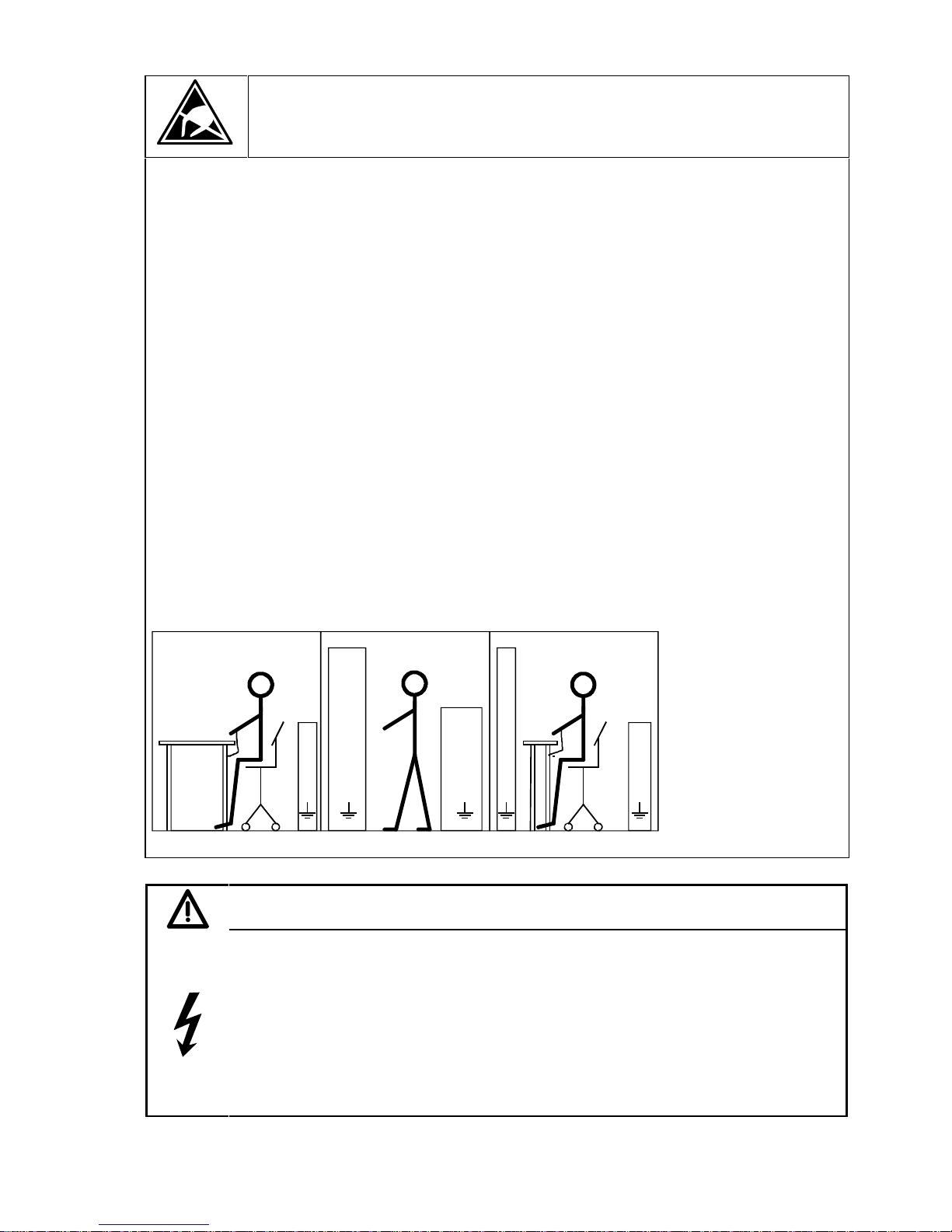
CAUTION
Electrostatically sensitive devices
The converter contains electrostatically sensitive devices. These can easily be destroyed if they are not
handled correctly. If, however, it is absolutely essential for you to work on electronic modules, please pay
careful attention to the following instructions:
• Electronic modules (PCBs) should not be touched unless work has to be carried out on them.
• Before touching a PCB, the person carrying out the work must himself be electrostatically discharged.
The simplest way of doing this is to touch an electrically conductive earthed object, e.g. socket outlet
earth contact.
• PCBs must not be allowed to come into contact with electrically insulating materials − plastic foil,
insulating table tops or clothing made of synthetic fibres −
• PCBs may only be set down or stored on electrically conducting surfaces.
• When carrying out soldering jobs on PCBs, make sure that the soldering tip has been earthed.
• PCBs and electronic components should generally be packed in electrically conducting containers (such
as metallized-plastic boxes or metal cans) before being stored or shipped.
• If the use of non-conducting packing containers cannot be avoided, PCBs must be wrapped in a
conducting material before being put in them. Examples of such materials include electrically conducting
foam rubber or household aluminium foil.
For easy reference, the protective measures necessary when dealing with sensitive electronic components
are illustrated in the sketches below.
a = Conductive flooring d = Anti-static overall
b = Anti-static table e = Anti-static chain
c = Anti-static footwear f = Earthing connections of cabinets
a
b
e
d
f f f
d
a
c
e
d
f f
b
c
a
Seated workstation Standing workstation Standing/seated workstation
WARNING
Hazardous voltages and rotating parts (fans) are present in this electrical equipment during
operation.
Non-observance of the safety instructions can result in death, severe personal injury or
substantial property damage.
Only qualified personnel should work on or around the equipment after first becoming
thoroughly familiar with all warning and safety notices and maintenance procedures contained
herein.
The successful and safe operation of this equipment is dependent on proper handling,
installation, operation and maintenance.

Safety Information 02.00
1-4 SIEMENS AG 6RX1700-0AD76
SIMOREG DC Master Operating Instrc tions
02.00 Type spectrum
Siemens AG 6RX1700-0AD76 2-1
SIMOREG DC Master Operating Instruc tions
2 Type spectrum
850A converter 2000A converter 1200A converter 600A converter
30A converter

Type spectrum 02.00
2-2 Siemens AG 6RX1700-0AD76
SIMOREG DC Master Operating Instruc tions
Converter order no. Type designation
–––––––––––––––––––––––––––––––––––––––––––––––––––––––––––––––––
6RA7018 - 6DS22 - 0 D485 / 30 Mre - GeE6S22
6RA7025 - 6DS22 - 0 D485 / 60 Mre - GeE6S22
6RA7028 - 6DS22 - 0 D485 / 90 Mre - GeE6S22
6RA7031 - 6DS22 - 0 D485 / 125 Mre - GeE6S22
6RA7075 - 6DS22 - 0 D485 / 210 Mre - GeEF6S22
6RA7078 - 6DS22 - 0 D485 / 280 Mre - GeEF6S22
6RA7081 - 6DS22 - 0 D485 / 400 Mre - GeEF6S22
6RA7085 - 6DS22 - 0 D485 / 600 Mre - GeEF6S22
6RA7087 - 6DS22 - 0 D485 / 850 Mre - GeEF6S22
6RA7091 - 6DS22 - 0 D485 / 1200 Mre - GeEF6S22
6RA7093 - 4DS22 - 0 D485 / 1600 Mre - GeEF4S22
6RA7095 - 4DS22 - 0 D485 / 2000 Mre - GeEF4S22
6RA7018 - 6FS22 - 0 D550 / 30 Mre - GeE6S22
6RA7025 - 6FS22 - 0 D550 / 60 Mre - GeE6S22
6RA7028 - 6FS22 - 0 D550 / 90 Mre - GeE6S22
6RA7031 - 6FS22 - 0 D550 / 125 Mre - GeE6S22
6RA7075 - 6FS22 - 0 D550 / 210 Mre - GeEF6S22
6RA7078 - 6FS22 - 0 D550 / 280 Mre - GeEF6S22
6RA7082 - 6FS22 - 0 D550 / 450 Mre - GeEF6S22
6RA7085 - 6FS22 - 0 D550 / 600 Mre - GeEF6S22
6RA7087 - 6FS22 - 0 D550 / 850 Mre - GeEF6S22
6RA7091 - 6FS22 - 0 D550 / 1200 Mre - GeEF6S22
6RA7025 - 6GS22 - 0 D690 / 60 Mre - GeE6S22
6RA7031 - 6GS22 - 0 D690 / 125 Mre - GeE6S22
6RA7075 - 6GS22 - 0 D690 / 210 Mre - GeEF6S22
6RA7081 - 6GS22 - 0 D690 / 400 Mre - GeEF6S22
6RA7085 - 6GS22 - 0 D690 / 600 Mre - GeEF6S22
6RA7087 - 6GS22 - 0 D690 / 800 Mre - GeEF6S22
6RA7090 - 6GS22 - 0 D690 / 1000 Mre - GeEF6S22
6RA7093 - 4GS22 - 0 D690 / 1600 Mre - GeEF4S22
6RA7095 - 4GS22 - 0 D690 / 2000 Mre - GeEF4S22
6RA7086 - 6KS22 - 0 D830 / 720 Mre - GeEF6S22
6RA7088 - 6KS22 - 0 D830 / 950 Mre - GeEF6S22
6RA7093 - 4KS22 - 0 D830 / 1500 Mre - GeEF4S22
6RA7095 - 4KS22 - 0 D830 / 2000 Mre - GeEF4S22
6RA7088 - 6LS22 - 0 D1000 / 900 Mre - GeEF6S22
6RA7093 - 4LS22 - 0 D1000 /1500 Mre - GeEF4S22
6RA7095 - 4LS22 - 0 D1000 /1900 Mre - GeEF4S22
Rated Rated
DC voltage DC current

02.00 Type spectrum
Siemens AG 6RX1700-0AD76 2-3
SIMOREG DC Master Operating Instruc tions
Converter order no. Type designation
–––––––––––––––––––––––––––––––––––––––––––––––––––––––––––––––––
6RA7013 - 6DV62 - 0 D420 / 15 Mreq - GeG6V62
6RA7018 - 6DV62 - 0 D420 / 30 Mreq - GeG6V62
6RA7025 - 6DV62 - 0 D420 / 60 Mreq - GeG6V62
6RA7028 - 6DV62 - 0 D420 / 90 Mreq - GeG6V62
6RA7031 - 6DV62 - 0 D420 / 125 Mreq - GeG6V62
6RA7075 - 6DV62 - 0 D420 / 210 Mreq - GeGF6V62
6RA7078 - 6DV62 - 0 D420 / 280 Mreq - GeGF6V62
6RA7081 - 6DV62 - 0 D420 / 400 Mreq - GeGF6V62
6RA7085 - 6DV62 - 0 D420 / 600 Mreq - GeGF6V62
6RA7087 - 6DV62 - 0 D420 / 850 Mreq - GeGF6V62
6RA7091 - 6DV62 - 0 D420 / 1200 Mreq - GeGF6V62
6RA7093 - 4DV62 - 0 D420 / 1600 Mreq - GeGF4V62
6RA7095 - 4DV62 - 0 D420 / 2000 Mreq - GeGF4V62
6RA7018 - 6FV62 - 0 D480 / 30 Mreq - GeG6V62
6RA7025 - 6FV62 - 0 D480 / 60 Mreq - GeG6V62
6RA7028 - 6FV62 - 0 D480 / 90 Mreq - GeG6V62
6RA7031 - 6FV62 - 0 D480 / 125 Mreq - GeG6V62
6RA7075 - 6FV62 - 0 D480 / 210 Mreq - GeGF6V62
6RA7078 - 6FV62 - 0 D480 / 280 Mreq - GeGF6V62
6RA7082 - 6FV62 - 0 D480 / 450 Mreq - GeGF6V62
6RA7085 - 6FV62 - 0 D480 / 600 Mreq - GeGF6V62
6RA7087 - 6FV62 - 0 D480 / 850 Mreq - GeGF6V62
6RA7091 - 6FV62 - 0 D480 / 1200 Mreq - GeGF6V62
6RA7025 - 6GV62 - 0 D600 / 60 Mreq - GeG6V62
6RA7031 - 6GV62 - 0 D600 / 125 Mreq - GeG6V62
6RA7075 - 6GV62 - 0 D600 / 210 Mreq - GeGF6V62
6RA7081 - 6GV62 - 0 D600 / 400 Mreq - GeGF6V62
6RA7085 - 6GV62 - 0 D600 / 600 Mreq - GeGF6V62
6RA7087 - 6GV62 - 0 D600 / 850 Mreq - GeGF6V62
6RA7090 - 6GV62 - 0 D600 / 1100 Mreq - GeGF6V62
6RA7093 - 4GV62 - 0 D600 / 1600 Mreq - GeGF4V62
6RA7095 - 4GV62 - 0 D600 / 2000 Mreq - GeGF4V62
6RA7086 - 6KV62 - 0 D725 / 760 Mreq - GeGF6V62
6RA7090 - 6KV62 - 0 D725 / 1000 Mreq - GeGF6V62
6RA7093 - 4KV62 - 0 D725 / 1500 Mreq - GeGF4V62
6RA7095 - 4KV62 - 0 D725 / 2000 Mreq - GeGF4V62
6RA7088 - 6LV62 - 0 D875 / 950 Mreq - GeGF6V62
6RA7093 - 4LV62 - 0 D875 /1500 Mreq - GeGF4V62
6RA7095 - 4LV62 - 0 D875 /1900 Mreq - GeGF4V62
Rated Rated
DC voltage DC current
Type spectrum 02.00
2-4 Siemens AG 6RX1700-0AD76
SIMOREG DC Master Operating Instruc tions
2.1 Converter order no. code
6RA - - 0-
Code letters defined acc. Options:
to general MLFB guidelines:
Z: With option
Converter model:
Innovation
23: SIMOREG Comp. 4th Gen.
24: SIMOREG Comp. 4th Gen. Di
g
ital
Closed-loop control:
70: SIMOREG DC Master
1: Uncontrolled field
2: Controlled field
Closed-loop control:
Rated DC currents and cooling:
1: 1Q analo
g
Natural cooling: Separate coolin
g
2: 1Q digital
Ambient temp. Ambient temp.
+45°C +35°C / +40°C on 6RA70 7: 4Q analo
g
6: 4Q digital
00: 50
01: 3.6.......<4.1 51
02: 4.1.......<4.65 52
Converter connection:
03: 4.65.....<5.25 53
04: 5.25.....<6.0 54 A:
05: 6.0.......<6.8 55 B:
06: 6.8.......<7.75 56 C:
07: 7.75.....<8.8 57
D: B2HZ (1Q)
08: 8.8.......<10.0 58 .
09: 59 .
10: 10.0.....<11.5 60: 31.5.....<36.0
K: (B2) A (B2) C (4Q)
11: 11.5.....<13.0 61: 36.0.....<41.0 .
12: 13.0.....<14.5 62: 41.0.....<46.5 .
13: 14.5.....<16.5 63: 46.5.....<52.5
S: B6C (1Q)
14: 16.5.....<19.0 64: 52.5.....<60.0 T:
15: 19.0.....<21.5 65: 60.0.....<68.0 U:
16: 21.5.....<24.5 66: 68.0.....<77.5
V: (B6) A (B6) C (4Q)
17: 24.5.....<28.0 67: 77.5.....<88.0
18: 28.0.....<31.5 68: 88.0.....<100
19: 69:
Rated supply voltage:
20: 31.5.....<36.0 70: 100......<115
21: 36.0.....<41.0 71: 115......<130 A:
22: 41.0.....<46.5 72: 130......<145
B: 230V
23: 46.5.....<52.5 73: 145......<165 C:
24: 52.5.....<60.0 74: 165......<190
D: 400V
25: 60.0.....<68.0 75: 190......<215 E:
26: 68.0.....<77.5 76: 215......<245
F: 440V - 480V
27: 77.5.....<88.0 77: 245......<280
G: 500V - 575V
28: 88.0.....<100 78: 280......<315
H: 660V
29: 79:
K: 690V - 750V
30: 100......<115 80: 315.......<360 L: 830V
31: 115......<130 81: 360.......<410
32: 130......<145 82: 410...... <465
Thyristor construction
33: 145......<165 83: 465...... <525
and fuse assembly:
34: 165......<190 84: 525...... <600
35: 190......<215 85: 600...... <680 0: Control units without power section
36: 215......<245 86: 680...... <775
1: USA Power
37: 245......<280 87: 775...... <880
2: USA Base
38: 280......<315 88: 880...... <1000 3: Disk thyristors, produced in China
39: 89: 4: Disk th
y
ristors with fuse assembl
y
40: 90: 1000..... <1150 5: Thyristor modules, produced i n Chi na
41: 91: 1150..... <1300
6: Thyristor modules
42: 92: 1300..... <1450 7:
43: 93: 1450..... <1650 8: ANL
44: 94::1650..... <1900 9:
45: 95: 1900..... <2150
02.00 Type spectrum
Siemens AG 6RX1700-0AD76 2-5
SIMOREG DC Master Operating Instruc tions
2.2 Ordering information for options using codes
SIMOREG converter order no. with suffix Z
and
codes (several codes together) and/or
plaintext (if required)
Options Codes Order No.
Technology software in the basic converter ("Free function
blocks")
S00 6RX1700-0AS00
Module terminal expansion (CUD2) K01 6RX1700-0AK01
SIMOVIS PC - PMU (RS232) connecting cable, 3m 6SX7005-0AB00
SU1 RS232 - RS485 iInterface converter, including mounting
accessories, main connection: 1CA 115V / 230V
- 6SX7005-0AA00
User-friendly operator control panel (OP1S) 6SE7090-0XX84-2FK0
AOP1 adapter for mounting OP1A in cubicle door, including
5 m connecting cable
6SX7010-0AA00
PMU-OP1S connecting cable, 3m 6SX7010-0AB03
PMU-OP1S connecting cable, 5m - 6SX7010-0AB05
LBA Local bus adapter for the electronics box
LBA is always needed to install supplementary boards
(see Section 5.2.2)
6SE7090-0XX84-4HA0
ADB Adapter board
ADB is always needed to install CBC, CBP, EB1, EB2,
SBP and SLB boards
6SE7090-0XX84-0KA0
SBP Pulse encoder evaluation board
1) 2) 3)
(miniature-format board; ADB required)
6SX7010-0FA00
EB1 Terminal expansion board
3)
(miniature-format board; ADB required)
6SE7090-0XX84-0KB0
EB2 Terminal expansion board
3)
(miniature-format board; ADB required)
6SE7090-0XX84-0KC0
SLB SIMOLINK board
1) 3)
(miniature-format board; ADB required)
6SX7010-0FJ00
CBP2 Communications board with interface for SINEC- L2-
DP, (PROFIBUS)
1) 3)
(miniature-format board; ADB required)
6SX7010-0FF05
CBC Communications board with interface for CAN protocol
1) 3)
(miniature-format board; ADB required)
6SX7010-0FG00
CB1 Communications board with interface for SINEC- L2-DP
(PROFIBUS)
3)
The replacement CBP board should be used for new
applications
Operating instructions (german and english)
6SE7090-0XX84-0AK0
6SE7087-6CX84-0AK0
6RA7 00 Z
Type spectrum 02.00
2-6 Siemens AG 6RX1700-0AD76
SIMOREG DC Master Operating Instruc tions
Options Codes Order No.
CB2 Communications board with interface for CAN protocol
3)
The replacement CBC board should be used for new
applications
Description
6SE7090-0XX84-0AE0
6SE7087-6CX84-0AK0
T100 module incl. hardware operating instructions without
software module)
3)
6SE7090-0XX87-0BB0
Hardware operating instructions for T100 6SE7080-0CX87-0BB0
MS100 "Universal Drive“ software module for T100 (EPROM)
without manual
6SE7098-0XX84-0BB0
Manual for MS100 "Universal Drive" software module
German 6SE7080-0CX84-0BB1
English 6SE7087-6CX84-0BB1
French 6SE7087-7CX84-0BB1
Spanish 6SE7087-8CX84-0BB1
Italian 6SE7087-2CX84-0BB1
T300 technology board with 2 connecting leads, SC58 and
SC60, terminal block SE300 and hardware operating
instructions
3)
- 6SE7090-0XX84-0AH0
T400 technology board (incl. short description)
3)
T400 hardware and configuring manual
- 6DD1606-0AD0
6DD1903-0EA0
Operating instructions for SIMOREG DC Master
Operating instructions in German D00 6RX1700-0AD00
Operating instructions in Italian D72 6RX1700-0AD72
Operating instructions in English D76 6RX1700-0AD76
Operating instructions in French D77 6RX1700-0AD77
Operating instructions in Spanish D78 6RX1700-0AD78
Operating Instructions and SIMOVIS in all the above
languages available on CD-ROM
D64 6RX1700-0AD64
1) The SBP, SLB and CBP boards can be ordered under two different numbers, i.e.
• under the order number of the board without accessories (such as connectors and Short Guide)
• as a retrofit kit: Board with connectors and Short Guide
Board Order number of board (w/o accessories) Order number of retrofit kit
ADB 6SE7090-0XX84-0KA0 6SE7010-0KA00
SBP 6SE7090-0XX84-0FA0 6SE7010-0FA00
EB1 6SE7090-0XX84-0KB0 6SE7010-0KB00
EB2 6SE7090-0XX84-0KC0 6SE7010-0KC00
SLB 6SE7090-0XX84-0FJ0 6SE7010-0FJ00
CBP2 6SE7090-0XX84-0FF5 6SE7010-0FF05
CBC 6SE7090-0XX84-0FG0 6SE7010-0FG00

02.00 Type spectrum
Siemens AG 6RX1700-0AD76 2-7
SIMOREG DC Master Operating Instruc tions
The retrofit kit must be ordered to install boards in the SMOREG converter so that the correct connectors
for system cabling and the Short Guide are also available.
The LBA local bus adapter and ADB adapter board must be ordered as additional components for
installing supplementary boards in the SIMOREG converter. These adapters are available under separate
order numbers.
2) A pulse encoder evaluation circuit is a standard component of the basic SIMOREG converter. The SBP
need therefore be ordered only in configurations requiring evaluation of a second pulse encoder.
3) An LBA local bus adapter is required to install this board in a SIMOREG converter. The adapter is
available under a separate order number.

Type spectrum 02.00
2-8 Siemens AG 6RX1700-0AD76
SIMOREG DC Master Operating Instruc tions

02.00 Description
Siemens AG 6RX1700-0AD76 3-1
SIMOREG DC Master Operating Instruc tions
3 Description
3.1 Applications
Series 6RA70 SIMOREG DC MASTER converters are fully digital, compact units for three-phase
supply which supply the armature and field of variable-speed DC drives with rated armature
currents of between 15A and 2000A. The compact converters can be connected in parallel to
supply currents of up to 10000A. The field circuit can be supplied with currents of up to 40A (current
levels depend on the armature rated current).
3.2 Design
Series 6RA70 SIMOREG DC MASTER converters are characterized by their compact, spacesaving construction. Their compact design makes them particularly easy to service and maintain
since individual components are readily accessible. The electronics box contains the basic
electronic circuitry as well as any supplementary boards.
All SIMOREG DC MASTER units are equipped with a PMU simple operator panel mounted in the
converter door. The panel consists of a five-digit, seven-segment display, three LEDs as status
indicators and three parameterization keys. The PMU also features connector X300 with a USS
interface in accordance with the RS232 or RS485 standard.
The panel provides all the facilities for making adjustments or settings and displaying measured
values required to start up the converter.
The OP1S optional converter operator panel can be mounted either in the converter door or
externally, e.g. in the cubicle door. For this purpose, it can be connected up by means of a 5 m long
cable. Cables of up to 200 m in length can be used if a separate 5 V supply is available. The OP1S
is connected to the SIMOREG via connector X300. The OP1S can be installed as an economic
alternative to control cubicle measuring instruments which display physical measured quantities.
The OP1S features an LCD with 4 x 16 characters for displaying parameter names in plaintext.
German, English, French, Spanish and Italian can be selected as the display languages.
The OP1S can store parameter sets for easy downloading to other devices.
The converter can also be parameterized on a standard PC with appropriate software connected to
the serial interface on the basic unit. This PC interface is used during start-up, for maintenance
during shutdown and for diagnosis in operation. Furthermore, converter software upgrades can be
loaded via this interface for storage in a Flash memory.
On single-quadrant converters, the armature is supplied via a fully controlled three-phase bridge
B6C and, on four-quadrant devices, via two fully controlled three-phase bridges in circulatingcurrent-free, inverse-parallel connection (B6)A(B6)C.
The field is supplied via a single-phase, branch-pair half-controlled 2-pulse bridge connection
B2HZ.
The frequencies of the armature and field supply voltages may be different (in a range from 45 to
65 Hz). The armature circuit supply phase sequence is insignificant.
For converters with 15A to 850A (1200A at 400V supply voltage) rated DC current, the power
section for armature and field is constructed of isolated thyristor modules. The heat sink is thus
electrically isolated. On devices with a higher rated DC current, the power section for the armature
circuit is constructed of disk thyristors and heat sinks (thyristor assemblies) at voltage potential. The
housing and terminal covers on power connections provide protection against accidental contact for
operators working in the vicinity. All connecting terminals are accessible from the front.
The power section cooling system is monitored by means of temperature sensors.

Description 02.00
3-2 Siemens AG 6RX1700-0AD76
SIMOREG DC Master Operating Instruc tions
3.2.1 Special features of devices with 460V rated connection voltage
• This device series is available with rated direct currents of 30A to 1200A.
• Devices with rated direct currents of 450A to 1200A are equipped with a 1-phase fan.
• On devices with rated direct currents of 60A to 850A, the power terminals are located on the
underside and on the top of the device.
3.3 Mode of operation
All open-loop and closed-loop drive control and communication functions are performed by two
powerful microprocessors. Drive control functions are implemented in the software as program
modules which can be "wired up" by parameters.
The rated DC currents (continuous DC currents), load class Ι, specified on the rated plate can be
exceeded by 180%, the permissible overload during being dependent on individual converters. The
microprocessor calculates the current I
2
t value of the power section cyclically to ensure that the
thyristors are not damaged in overload operation.
A selection table for overload operation can be found in Section 9 ”Description of functions".
Converters self-adapt to the frequency of the available supply voltage in the range from 45 to 65 Hz
(armature and field are independent)
02.00 Description
Siemens AG 6RX1700-0AD76 3-3
SIMOREG DC Master Operating Instruc tions
3.4 Technical data
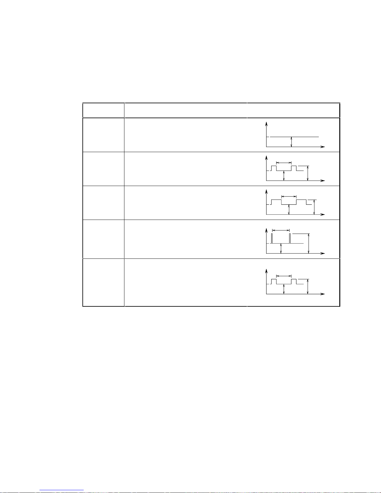
3.4.1 Load types
To adapt the SIMOREG DC Master to the load profile of the working machine as efficiently as
possible, you can dimension it using the load cycle.
The setting on the SIMOREG DC Master is made in parameter P067.
Load class Load for converter Load cycle
DC I
(P067=1)
I
DC I
continuous (IdN)
100%
DC II
(P067=2)
I
DC II
for 15 min and 1.5 x I
DC II
for 60 s
100%
150%
15min
DC III
(P067=3)
I
DC III
for 15 min and 1.5 x I
DC III
for 120 s
100%
150%
15min
DC IV
(P067=4)
I
DC IV
for 15 min and 2 x I
DC IV
for 10 s
100%
200%
15min
US rating
(P067=5)
I
US
for 15 min and 1.5 x IUS for 60 s
Note:
In this setting, an ambient or coolant
temperature of 45°C is permissible for all
device types.
100%
150%
15min
Description 02.00
3-4 Siemens AG 6RX1700-0AD76
SIMOREG DC Master Operating Instruc tions
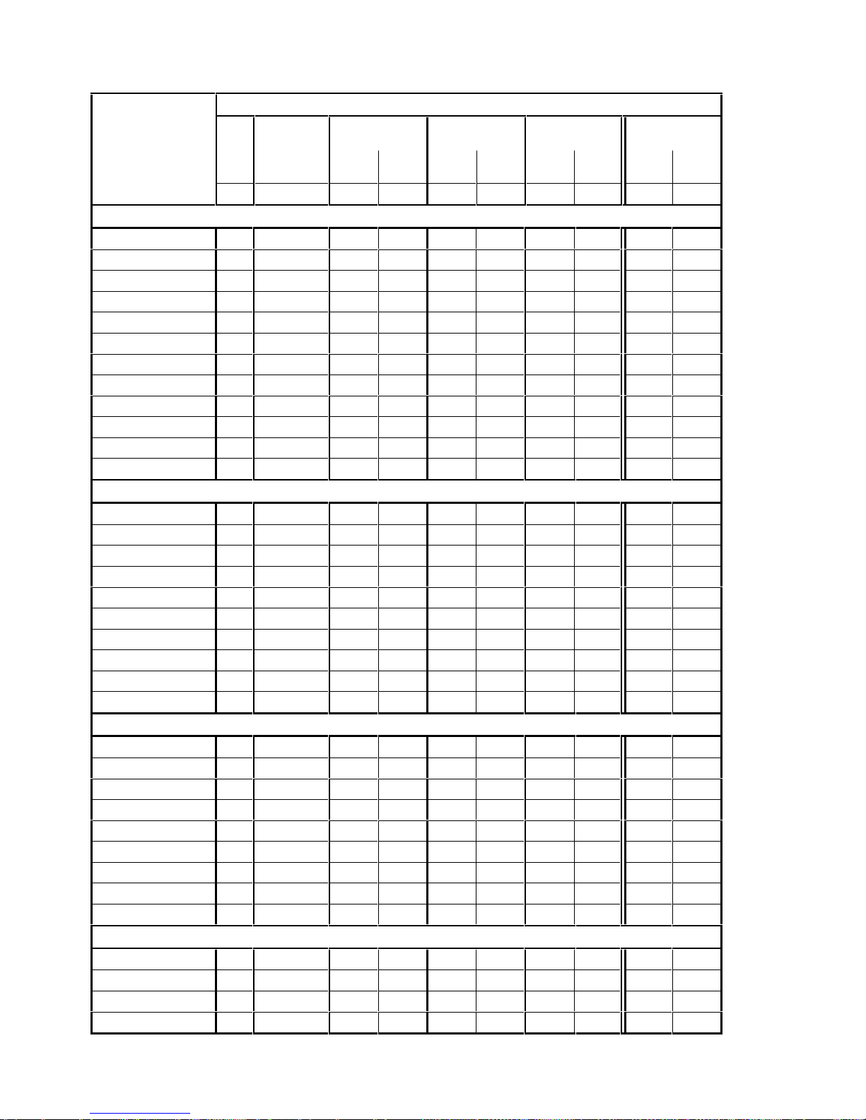
3.4.1.1 Load cycles for 1Q applications
Load cycles
Tu DC I DC II DC III DC IV
US rating
Tu=45°C
continuous 15min
100%
60sec
150%
15min
100%
120 sec
150%
15min
100%
10sec
200%
15min
100%
60sec
150%
Recommended
SIMOREG DC Master
° C A AAAAAAAA
400V, 1Q
6RA7018-6DS22 45 30 25,0 37,5 24,0 36,0 22,4 44,8 25, 0 37,5
6RA7025-6DS22 45 60 51,0 76, 5 50,0 75,0 46,5 93,0 51,0 76,5
6RA7028-6DS22 45 90 74,0 111,0 72,0 108,0 66,0 132,0 74,0 111,0
6RA7031-6DS22 45 125 105,0 158,0 100,0 150, 0 95,0 190,0 105,0 158,0
6RA7075-6DS22 40 210 165,0 247,5 161,0 241, 5 137,0 274,0 158,0 237,0
6RA7078-6DS22 40 280 227,0 340,5 218,0 327, 0 202,0 404,0 216,0 324,0
6RA7081-6DS22 40 400 290,0 435,0 281,0 421, 5 244,0 488,0 276,0 414,0
6RA7085-6DS22 40 600 463,0 694,5 446,0 669, 0 415,0 830,0 443,0 664,5
6RA7087-6DS22 40 850 652,0 978,0 622,0 933, 0 610,0 1220,0 620,0 930,0
6RA7091-6DS22 40 1200 880,0 1320,0 850,0 1275,0 790,0 1580,0 850,0 1275,0
6RA7093-4DS22 40 1600 1250,0 1875,0 1210,0 1815,0 1140,0 2280,0 1190,0 1785,0
6RA7095-4DS22 40 2000 1510,0 2265,0 1454,0 2181,0 1390,0 2780,0 1436,0 2154,0
460V, 1Q
6RA7018-6FS22 45 30 25,0 37,5 24,0 36,0 22,4 44,8 15,0 22,5
6RA7025-6FS22 45 60 51,0 76,5 50,0 75,0 46,5 93,0 30,0 45,0
6RA7028-6FS22 45 90 74,0 111,0 72,0 108, 0 66,0 132,0 60,0 90,0
6RA7031-6FS22 45 125 105,0 158,0 100,0 150,0 95,0 190,0 100,0 150,0
6RA7075-6FS22 40 210 165,0 247,5 161,0 241,5 137,0 274,0 140,0 210,0
6RA7078-6FS22 40 280 227,0 340,5 218,0 327,0 202,0 404,0 210,0 315,0
6RA7082-6FS22 40 450 320,0 480,0 311,0 466,5 275,0 550,0 255,0 382,5
6RA7085-6FS22 40 600 463,0 694,5 446,0 669,0 415,0 830,0 430,0 645,0
6RA7087-6FS22 40 850 652,0 978,0 622,0 933,0 610,0 1220,0 510,0 765,0
6RA7091-6FS22 40 1200 880, 0 1.320, 0 850,0 1275,0 790,0 1580,0 850,0 1275,0
575V, 1Q
6RA7025-6GS22 45 60 51,0 76,5 50,0 75,0 46,5 93,0 51,0 76,5
6RA7031-6GS22 45 125 105,0 158,0 100,0 150,0 95,0 190,0 105,0 158,0
6RA7075-6GS22 40 210 165,0 247,5 161,0 241,5 137,0 274,0 158,0 237,0
6RA7081-6GS22 40 400 290,0 435,0 281,0 421,5 244,0 488,0 276,0 414,0
6RA7085-6GS22 40 600 463,0 694,5 446,0 669,0 415,0 830,0 443,0 664,5
6RA7087-6GS22 40 800 608,0 912,0 582,0 873,0 560,0 1120,0 578,0 867,0
6RA7090-6GS22 40 1000 736,0 1104,0 714,0 1071,0 652,0 1304,0 700,0 1050,0
6RA7093-4GS22 40 1600 1250,0 1875,0 1210,0 1815,0 1140,0 2280,0 1190,0 1785,0
6RA7095-4GS22 40 2000 1660,0 2490,0 1590,0 2385,0 1570,0 3140,0 1660,0 2490,0
690V, 1Q
6RA7086-6KS22 40 720 552,0 828,0 528,0 792,0 518,0 1036,0 524,0 786,0
6RA7088-6KS22 40 950 710,0 1065,0 686,0 1029,0 635,0 1270,0 667, 0 1000, 0
6RA7093-4KS22 40 1500 1150,0 1725,0 1110,0 1665,0 1050,0 2100,0 1100,0 1650,0
6RA7095-4KS22 40 2000 1590,0 2385,0 1520,0 2280,0 1510,0 3020,0 1504,0 2256,0
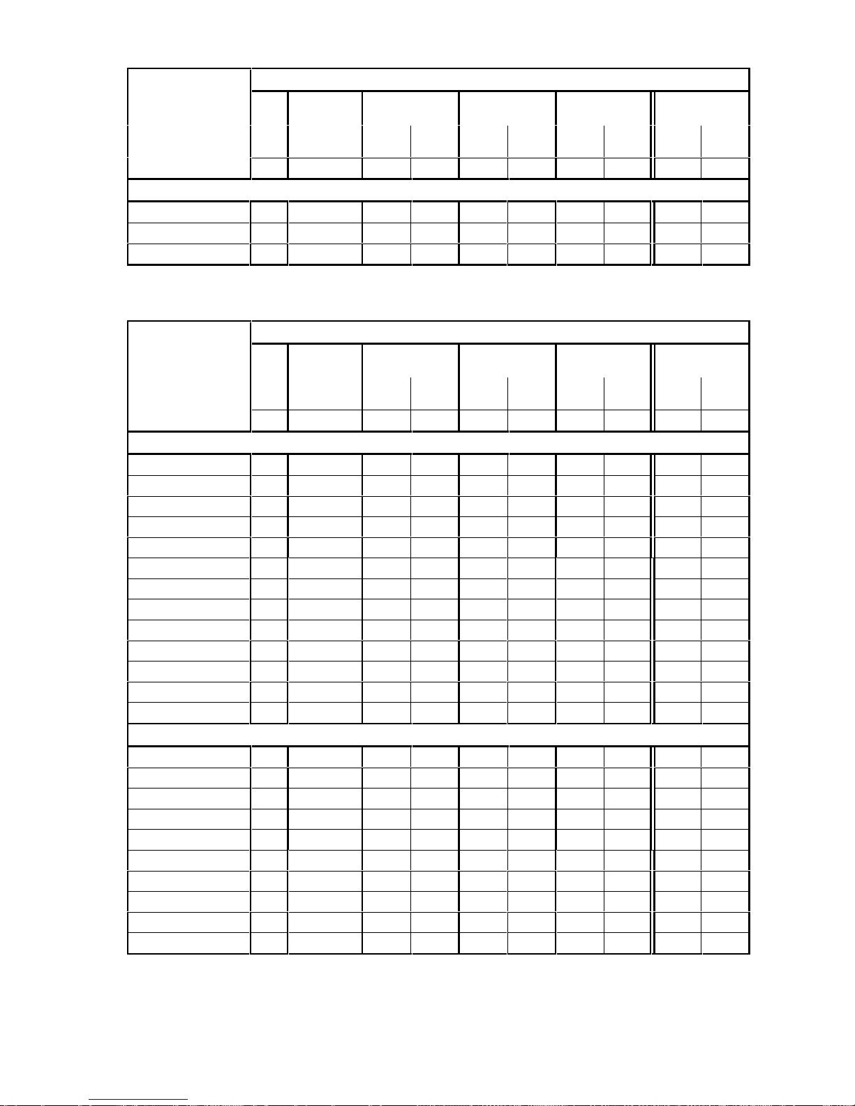
02.00 Description
Siemens AG 6RX1700-0AD76 3-5
SIMOREG DC Master Operating Instruc tions
Load cycles
Tu DC I DC II DC III DC IV
US rating
Tu=45°C
continuous 15min
100%
60sec
150%
15min
100%
120 sec
150%
15min
100%
10sec
200%
15min
100%
60sec
150%
Recommended
SIMOREG DC Master
° C A AAAAAAAA
830V, 1Q
6RA7088-6LS22 40 900 664,0 996,0 642,0 963,0 595,0 1190,0 632, 0 948,0
6RA7093-4LS22 40 1500 1150,0 1725,0 1110,0 1665,0 1040,0 2080,0 1100,0 1650,0
6RA7095-4LS22 40 1900 1486,0 2229,0 1420,0 2130,0 1400,0 2800,0 1412,0 2118,0
3.4.1.2 Load cycles for 4Q applications
Load cycles
Tu DC I DC II DC III DC IV
US rating
Tu=45°C
continuous 15min
100%
60sec
150%
15min
100%
120 sec
150%
15min
100%
10sec
200%
15min
100%
60sec
150%
Recommended
SIMOREG DC Master
° C A AAAAAAAA
400V, 4Q
6RA7013-6DV62 45 15 13,8 20,7 13,4 20,1 12,6 25,2 14,0 20,7
6RA7018-6DV62 45 30 25,0 37,5 24,0 36,0 22,4 44,8 25,0 37,5
6RA7025-6DV62 45 60 53,0 79,5 51,0 76,5 47,0 94,0 53,0 79,5
6RA7028-6DV62 45 90 79,0 118,5 76,0 114,0 72,5 145,0 79,0 118,5
6RA7031-6DV62 45 125 107,0 160,5 104,0 156, 0 96,0 192,0 107,0 160,5
6RA7075-6DV62 40 210 165,0 247,5 161,0 241, 5 137,0 274,0 158,0 237,0
6RA7078-6DV62 40 280 227,0 340,5 218,0 327, 0 202 404,0 216,0 324,0
6RA7081-6DV62 40 400 302,0 453,0 294,0 441, 0 250,0 500,0 286,0 429,0
6RA7085-6DV62 40 600 470,0 705,0 454,0 681, 0 412,0 826,0 450,0 675,0
6RA7087-6DV62 40 850 660,0 990,0 635,0 952, 5 580,0 1160,0 628,0 942,0
6RA7091-6DV62 40 1200 885,0 1327,5 858,0 1287,0 772,0 1544,0 850,0 1275,0
6RA7093-4DV62 40 1600 1250,0 1875,0 1210,0 1815,0 1140,0 2280,0 1190,0 1785,0
6RA7095-4DV62 40 2000 1480,0 2220,0 1435,0 2152,0 1332,0 2664,0 1402,0 2103,0
460V, 4Q
6RA7018-6FV62 45 30 25,0 37,5 24,0 36,0 22,4 44,8 15,0 22,5
6RA7025-6FV62 45 60 53,0 79,5 51,0 76,5 47,0 94,0 30,0 45,0
6RA7028-6FV62 45 90 79,0 118,5 76,0 114, 0 72,5 145,0 60,0 90,0
6RA7031-6FV62 45 125 107,0 160,5 104,0 156,0 96,0 192,0 100,0 150,0
6RA7075-6FV62 40 210 165,0 247,5 161,0 241,5 137,0 274,0 140,0 210,0
6RA7078-6FV62 40 280 227,0 340,5 218,0 327,0 202,0 404,0 210,0 315,0
6RA7082-6FV62 40 450 320,0 480 311,0 466,5 275,0 550, 0 255, 0 382,5
6RA7085-6FV62 40 600 470,0 705 454,0 681,0 412,0 826, 0 430, 0 645,0
6RA7087-6FV62 40 850 660,0 990 635,0 953,0 580,0 1160,0 510,0 765,0
6RA7091-6FV62 40 1200 885, 0 1327,5 858,0 1287,0 772,0 1544,0 850,0 1275,0
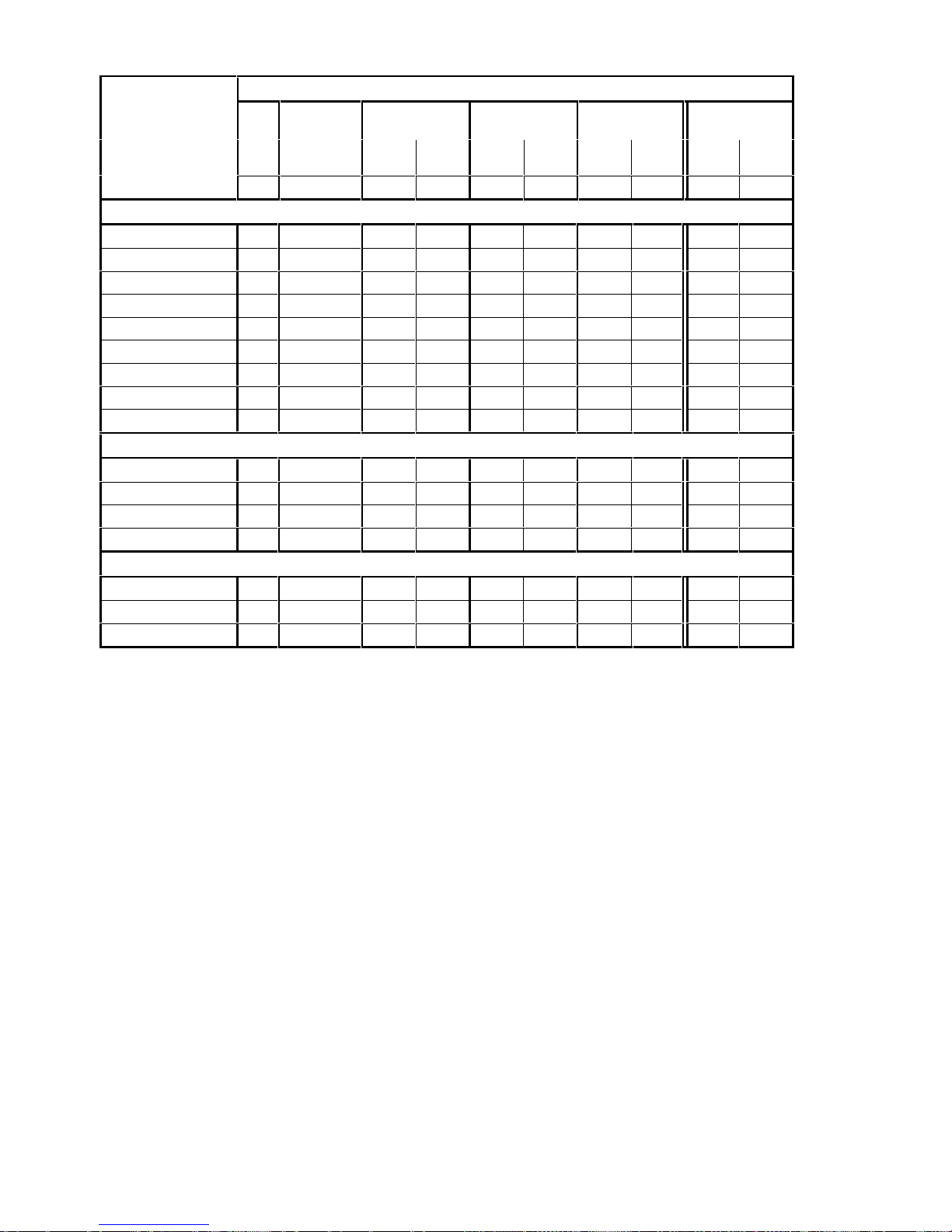
Description 02.00
3-6 Siemens AG 6RX1700-0AD76
SIMOREG DC Master Operating Instruc tions
Load cycles
Tu DC I DC II DC III DC IV
US rating
Tu=45°C
continuous 15min
100%
60sec
150%
15min
100%
120 sec
150%
15min
100%
10sec
200%
15min
100%
60sec
150%
Recommended
SIMOREG DC Master
° C A AAAAAAAA
575V, 4Q
6RA7025-6GV62 45 60 53,0 79,5 51,0 76,5 47,0 94,0 53,0 79,5
6RA7031-6GV62 45 125 107,0 160,5 104,0 156,0 96,0 192,0 107,0 160,5
6RA7075-6GV62 40 210 165,0 247,5 161,0 241,5 137,0 274,0 158,0 237,0
6RA7081-6GV62 40 400 302,0 453,0 294,0 441,0 250,0 500,0 286,0 429,0
6RA7085-6GV62 40 600 470,0 705,0 454,0 681,0 412,0 826,0 450,0 675,0
6RA7087-6GV62 40 850 660,0 990,0 635,0 952,5 580,0 1160,0 628,0 942,0
6RA7090-6GV62 40 1100 806,0 1209,0 782,0 1173,0 693,0 1386,0 765,0 1148,0
6RA7093-4GV62 40 1600 1250,0 1875,0 1210,0 1815,0 1140,0 2280,0 1190,0 1785,0
6RA7095-4GV62 40 2000 1660,0 2490,0 1590,0 2385,0 1570,0 3140,0 1660,0 2490,0
690V, 4Q
6RA7086-6KV62 40 760 600,0 900,0 576,0 864,0 536,0 1072,0 570,0 855,0
6RA7090-6KV62 40 1000 738,0 1107,0 716,0 1074,0 642,0 1284,0 702,0 1053,0
6RA7093-4KV62 40 1500 1160,0 1740,0 1130,0 1695,0 1040,0 2080,0 1110,0 1665,0
6RA7095-4KV62 40 2000 1480,0 2220,0 1435,0 2152,0 1332,0 2664,0 1402,0 2103,0
830V, 4Q
6RA7088-6LV62 40 950 700,0 1050,0 680,0 1020,0 610,0 1220,0 667,0 1000,0
6RA7093-4LV62 40 1500 1160,0 1740,0 1130,0 1695,0 1040,0 2080,0 1110,0 1665,0
6RA7095-4LV62 40 1900 1486,0 2229,0 1420,0 2130,0 1400,0 2800,0 1412,0 2118,0
02.00 Description
Siemens AG 6RX1700-0AD76 3-7
SIMOREG DC Master Operating Instruc tions
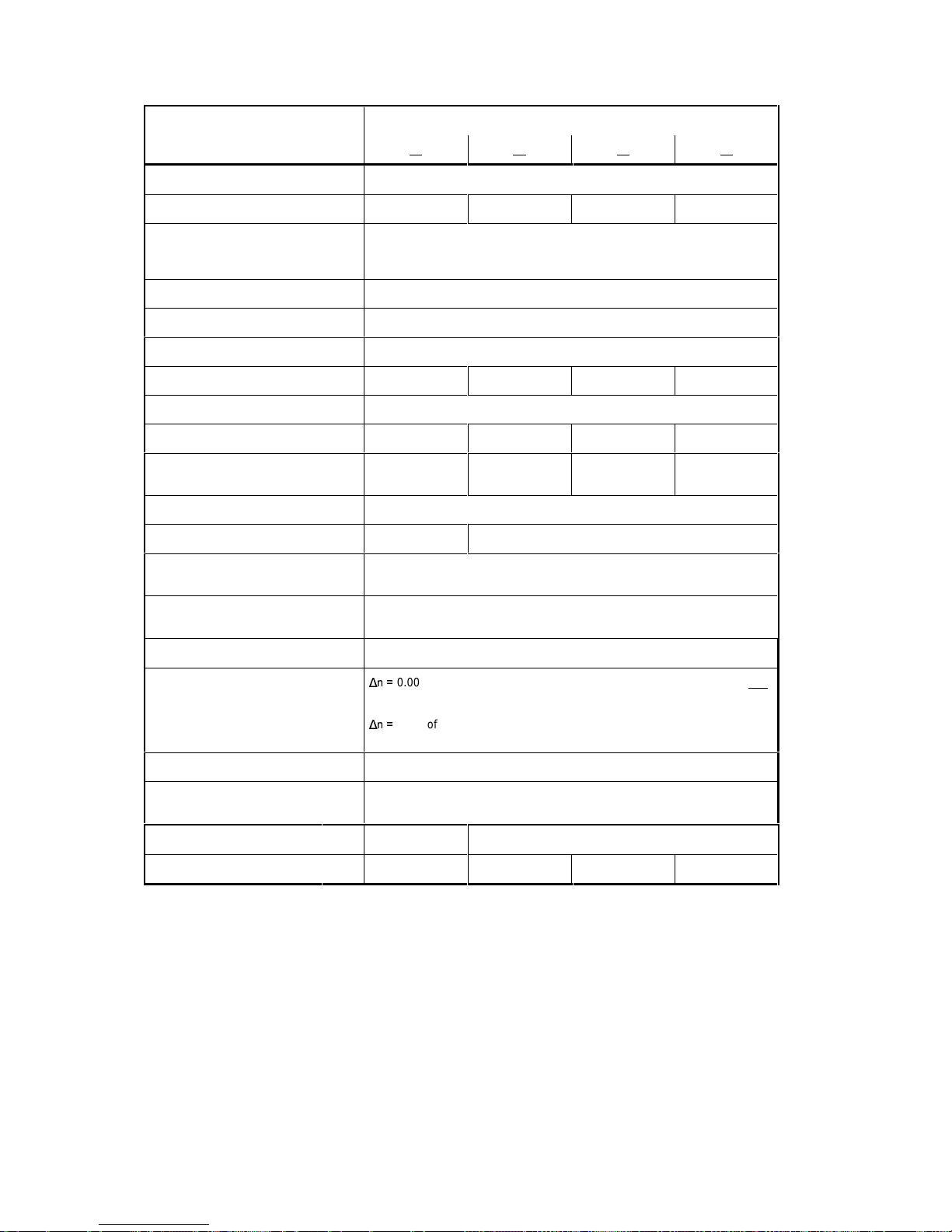
3.4.2 Converters 3AC 400V, 30A to 125A, 1Q
Order No. 6RA70 . . – 6DS22
18 25 28 31
Rated supply voltage armature 1)V 3AC 400 (+15% / – 20%)
Rated input current armature
2)
A 25 50 75 104
Rated supply voltage electronics
power supply
V 2AC 380 (– 25%) to 460 (+15%); In=1A oder
1AC 190 (– 25%) to 230 (+15%); In=2A
(– 35% for 1min)
Rated supply voltage field
1)
V 2AC 400 (+15% / – 20%)
7)
Rated frequency Hz 45 to 65
Rated DC voltage
1)
V 485
Rated DC current A 30 60 90 125
Overload capability
6)
max. 180% of rated DC current
Rated output kW 14, 5 29 44 61
Power loss at rated DC current
(approx.)
W 163 240 347 400
Rated DC voltage field
1)
V max. 325
Rated DC current field A 5 10
Operational ambient tem perature °C 0 to 45 at I
rated
3)
self-cooled
Storage and transport
temperature
°C – 25 to +70
Installation altit ude above sea level
≤ 1000 m at rated DC current
4)
Control stability
Q
0.006% of the rated motor s peed, valid for pulse encoder operation and
digital setpoint
Q
0.1% of the rated motor s peed, valid for analog tacho or analog
setpoint
5)
Environmental clas s DIN IEC 721-3-3 3K3
Degree of protect. DIN 40050
IEC 144
IP00
Dimensions (HxWxD) mm 385x265x239 385x265x283
Weights (approx.) kg 11 14 16 16
Explanation at end of list of tabl es
Description 02.00
3-8 Siemens AG 6RX1700-0AD76
SIMOREG DC Master Operating Instruc tions
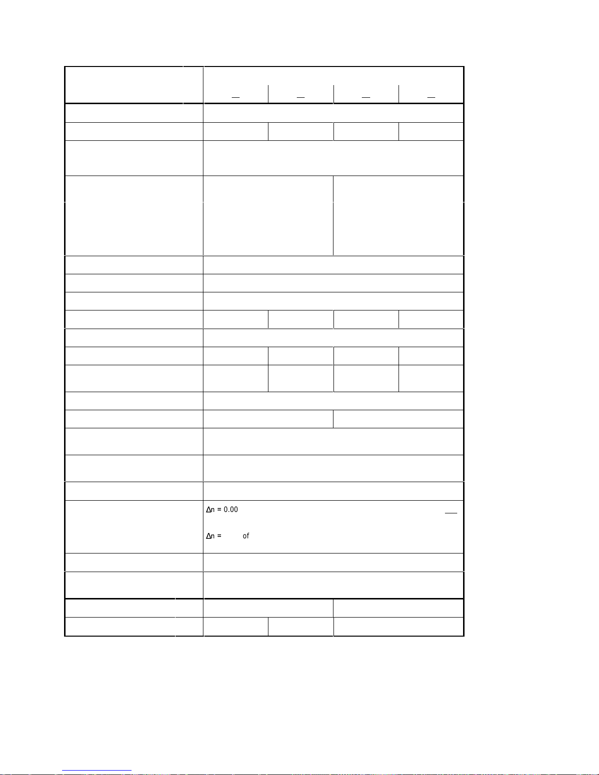
3.4.3 Converters 3AC 400V, 210A to 600A, 1Q
Order No. 6RA70 . . – 6DS22
75 78 81 85
Rated supply voltage armature 1)V 3AC 400 (+15% / – 20%)
Rated input current armature
2)
A 175 233 332 498
Rated supply voltage electronics
power supply
V 2AC 380 (– 25%) to 460 (+15%); In=1A oder
1AC 190 (– 25%) to 230 (+15%); In=2A
(– 35% for 1min)
Rated supply voltage fan V DC 24V internal 3AC 400 (±15%) 50Hz
3AC 460 (±10%) 60Hz
Fan rated current A 0,24
Air flow rate m3/h 100 570
Fan noise level dBA 40 73
Rated supply voltage field
1)
V 2AC 400 (+15% / – 20%)
7)
Rated frequency Hz 45 to 65
Rated DC voltage
1)
V 485
Rated DC current A 210 280 400 600
Overload capability
6)
max. 180% of rated DC current
Rated output kW 102 136 194 291
Power loss at rated DC current
(approx.)
W 676 800 1328 1798
Rated DC voltage field
1)
V max. 325
Rated DC current field A 15 25
Operational ambient tem perature °C 0 to 40 at I
rated
3)
forced-cooled
Storage and transport
temperature
°C – 25 to +70
Installation altit ude above sea level
≤ 1000 m at rated DC current
4)
Control stability
Q
0.006% of the rated motor s peed, valid for pulse encoder operation and
digital setpoint
Q
0.1% of the rated motor s peed, valid for analog tacho or analog
setpoint
5)
Environmental clas s DIN IEC 721-3-3 3K3
Degree of protect. DIN 40050
IEC 144
IP00
Dimensions (HxWxD) mm 385x265x283 625x268x318
Weights (approx.) kg 16 17 30
Explanation at end of list of tabl es
 Loading...