

Page 1

A&D LD CS 31 October 2007
FAQ for 6RA70 DC MASTER and SIMOREG CM
Question:
How can I manually record the field characteristic?
Answer:
The automatic optimization run P051 = 27 supports recording of the field characteristic. If this
routine cannot be used, the field characteristic needs to be recorded manually as described
below.
A field characteristic is required for motors which will also operate in the field-weakening
range. It must not be recorded for motors which will operate up to rated speed only.
Relationships:
The magnetic flux Φ is determined by the excitation current of the motor. When the excitation
current increases (up to its rated value), however, the flux Φ does not increase linearly
because the stator core becomes saturated. The relationship between the excitation current
and the flux is not linear and is represented by the field characteristic (magnetization
characteristic).
The induced motor voltage is the EMF of the motor.
EMF[V] = k * Φ * n[RPM]; the EMF reaches its rated value when the motor is operating at
rated speed. To prevent the motor EMF from reaching excessive values at speeds above the
motor rated speed, the flux Φ is reduced in this range and the EMF is regulated to a constant
value, i.e. the rated EMF value.
The following relation applies in steady-state motor operation: Ud – Id * Ra = EMF
Ud: Motor armature voltage, Id: Motor armature current, Ra: Armature resistance of motor
The maximum speed adjustment must be made before the field characteristic is recorded.
P741 for an analog tachometer or P143 for a pulse encoder. The maximum speed
adjustment must be made at a speed lower than rated speed.
The current controller and speed controller must then be optimized (Section 7.5 of Operating
Instructions). The field characteristic can then be recorded.
Recording of a motor field characteristic (magnetization characteristic):
To record the field characteristic, the magnetization characteristic is measured. This is done
by setting the field current setpoint
the motor
65.0 %, 60.5 %, 56.5 %, 53.0 %, 50.0 %, 47.0 %, 44.0 %, 41.0 %, 38.0 %, 35.0 %, 32.0 %,
29.0 %, 26.0 %, 23.0 %, 20.0 %, 17.0 %, 14.0 %, 11.0 %, 8.0 %.
At a given speed, therefore, a specific actual EMF value
value of the field current. The actual speed value
not decisive, but it is important that the speed is maintained at a constant value for each
single measuring point.
The EMF value
speed value is displayed in parameter r025.
I
, e.g. in the following increments: 91.0 %, 83.0 %, 76.0 %, 70.0 %,
motorratedfield
EMF for each measuring point is displayed in parameter r037. The actual
act
I , starting at 100.0 % of the rated excitation current of
fset
EMF is measured at each actual
act
n at the individual measuring points is
act
1
Page 2
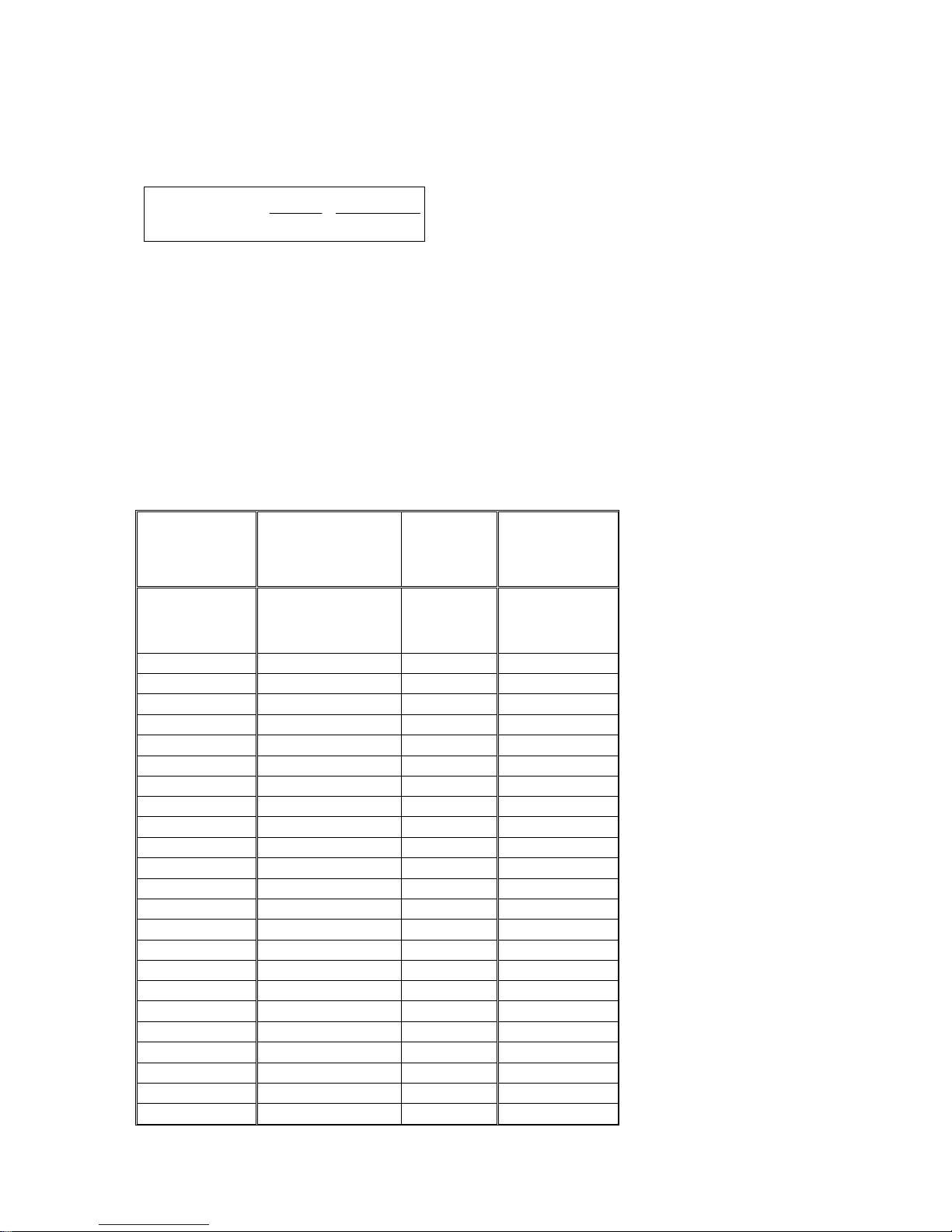
The flux values
Φ
setpoints
I are determined according to the formula defined below from the actual EMF
fset
normalized to rated flux which are reached at specific field current
)(
IΦ
fset
and speed values calculated and measured respectively and entered in a table of flux values.
I ∗∗=Φ %100)(
EMF
EMF
fset
act
EMF
n
act
,
... measured values in field-weakening range at specified
n
act
,
n
fieldrated
... measured values with rated field (100.0 % rated excitation current)
fieldrated
act
n
EMF
fieldrated
... in field-weakening range at specified
fieldrated
I
fset
I
fset
Settings:
P102: Rated excitation current motor
Set P103 = 0, minimum excitation current motor
P613.01 = 401, parameter P401 specifies the factor for the excitation current setpoint
(x 0 – 100%).
P433.01 = 402, parameter P402 specifies the speed setpoint.
The speed setpoint must be set to a value lower than the rated speed of the motor. Start
recording at approximately 80% of the rated motor EMF.
Procedure: Maintaining a constant speed for the various settings of P401 (starting at 100%),
enter r037 and r025 in the table and calculate Φ (I
fset
).
I in % of
fset
I
(rated field)
motorratedfield
P401
100.0 %
91.0 %
83.0 %
76.0 %
70.0 %
65.0 %
60.5 %
56.5 %
53.0 %
50.0 %
47.0 %
44.0 %
41.0 %
38.0 %
35.0 %
32.0 %
29.0 %
26.0 %
23.0 %
20.0 %
17.0 %
14.0 %
11.0 %
8.0 %
act
r037
=
fieldrated
n
n
act
r025
(=
fieldrated
acc. to formula
100.00 %
)
EMF
(=
EMF )
I
fset
above
)(
2
Page 3
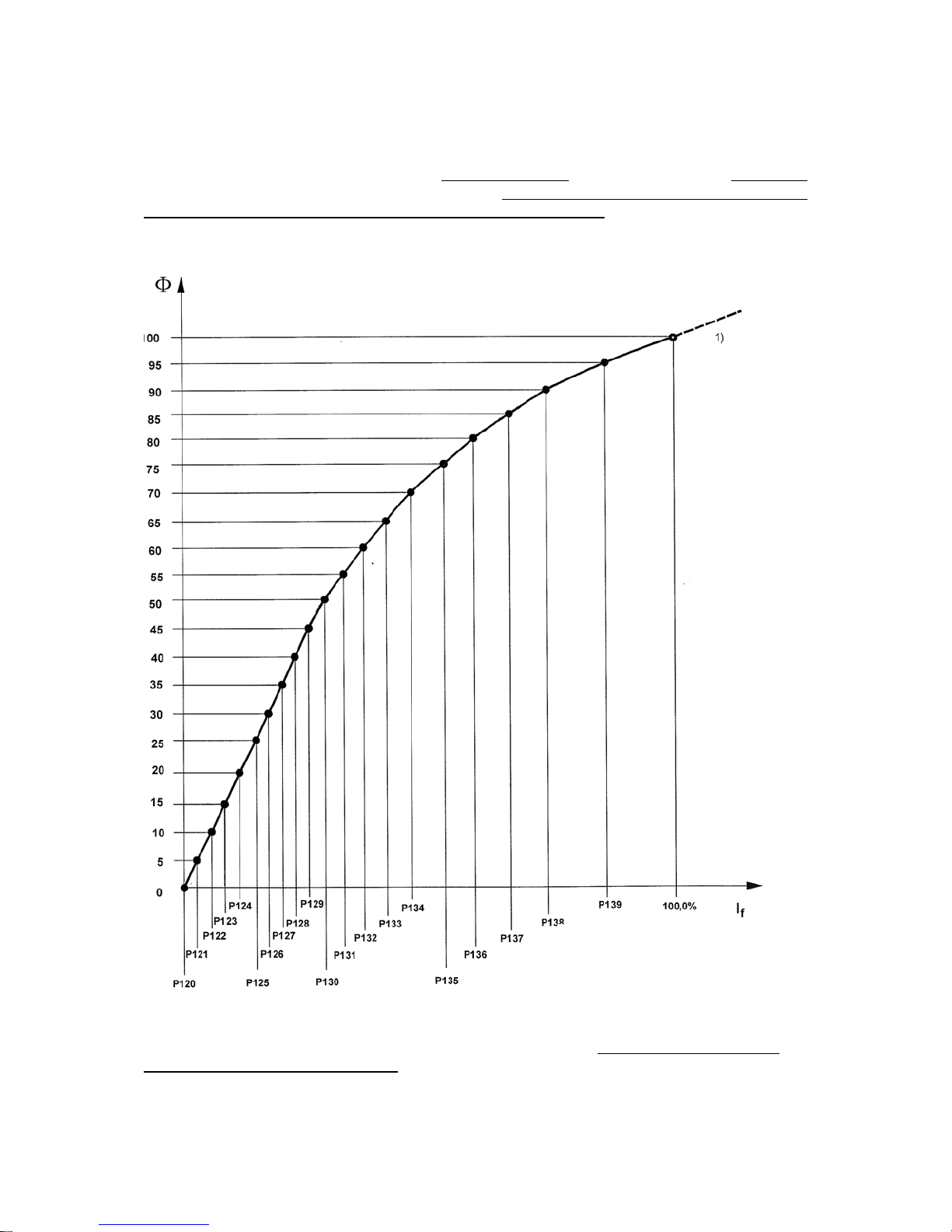
The field characteristic can be plotted on the basis of the field currents and calculated
normalized flux values entered in the table.
The field current values corresponding to linearly graduated
(in increments of 5%) flux values
can then be read off this plot and stored in the field characteristic parameters P121 (field
current at 5% flux) to P139 (field current at 95% machine flux)
(see Figure 1 below for an
example of a field characteristic plot).
Machine flux as % of rated flux
Figure 1. Example of a field characteristic – in this diagram, the field current as a % of the
rated excitation current of the motor is plotted along the x axis.
3
Field current as % of P102
Page 4
Parameter P118 (rated value of EMF)
∗
is calculated from the rated armature voltage of the
motor minus the voltage drop across the armature circuit resistance at the rated armature
current of the motor. P118 = P101 – P100 * P110.
The associated value of parameter P119 (rated speed)
is calculated as follows and specifies
the "cut-out" speed:
nEMFratedP
speedratedP
=
)(119
EMF
fieldratedatact
)(118
fieldratedatact
Further settings
P117 = 1
P081 = 1
(field characteristic parameters P118 to P139 are valid)
:
P613.01 = 1 Suppress influence of P401 on the field current setpoint
P433.01 =
P103 = xx
Set connector number for the speed setpoint
The minimum field current must be set slightly lower than required for maximum
speed.
Run the motor through the entire speed range and check whether a stable actual speed
value can be obtained. Re-optimize the speed controller / current controller if necessary.
EMF-dependent field-weakening using the EMF controller
without recording of the field characteristic:
For applications which do not require a high dynamic response to speed changes in the fieldweakening range, there is no need to record the field characteristic. In these cases, fieldweakening can be implemented solely via the EMF controller.
Settings:
P081 = 1
P117 = 1
P273.01 = 0
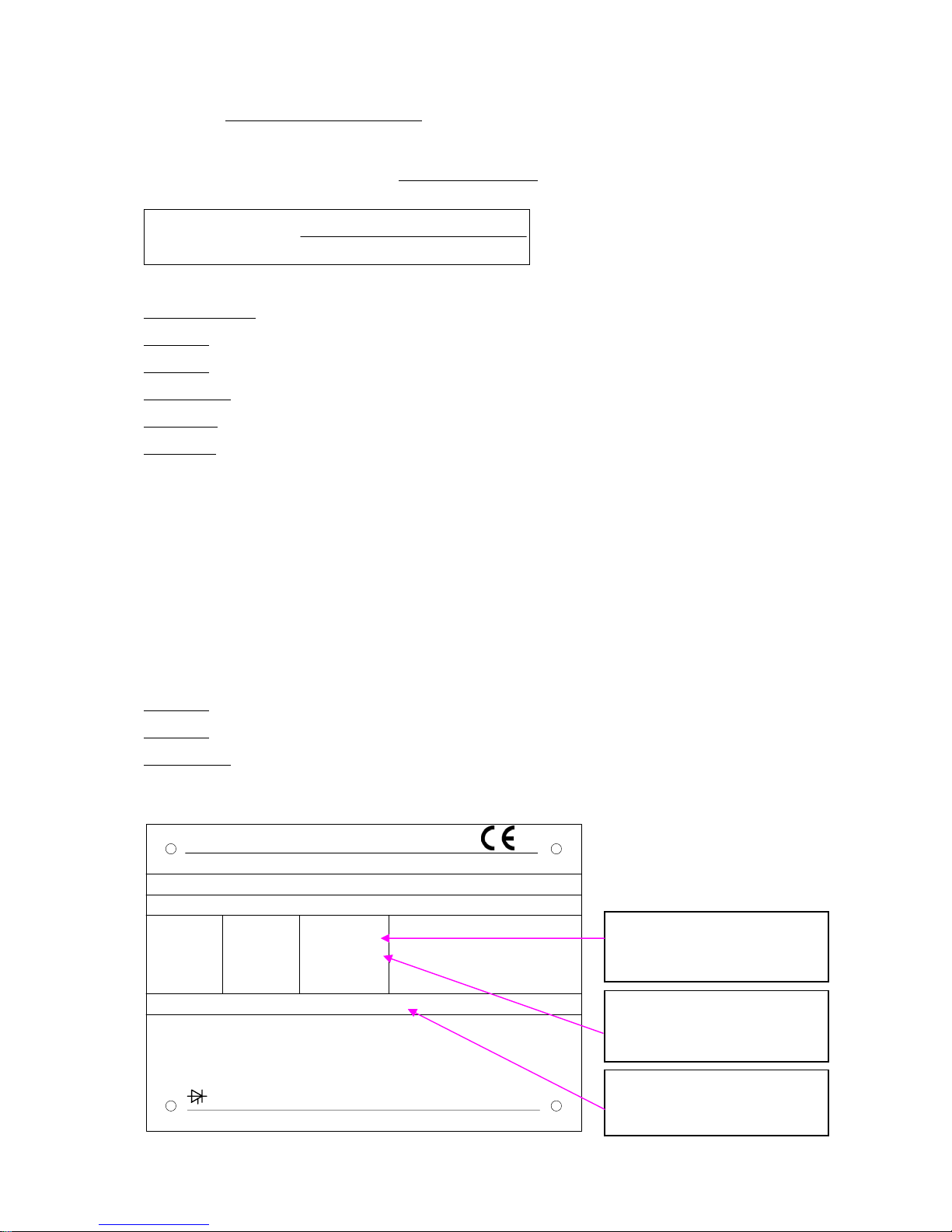
The motor rating plate:
SIEMENS
DC - Motor
No. N R7 1145783 010 001 / 2004
Wärmekl./Th.Cl. H
V
20 ... 420
420
A
985
990
1GG6286-0NG40-1VV1-Z
IP23 / IC 06 IM B3
1/min
10 ... 1410
1410 ... 1620
2,76 ... 390
EN 60034
Gew./Wt. 1,56 t
kW
390
Rated speed of the motor
1410 [RPM]
Fremderr./Separate excit.: 310 ... 210 V, 14,5 ... 11,5 A
Fremdkühlung/Separate cooling: 0,75 m
B6C, 400 V, 50 Hz
MADE IN GERMANY
4
3
/s
Luftrichtung/
Dir. of Ventilation
NDE-DE
Maximum field-weakening
speed of the motor
1620 [RPM]
Rated excitation current of
the motor 14.5 [A]
 Loading...