

Page 1

Rehm
SIMOMED HM
Service Instructions
SIMOMED
AX
44 cm / 54 cm Monitor
44 cm Monitor Part No. 37 92 079 X2077
54 cm Monitor Part No. 37 92 087 X2078
54 cm Monitor Part No. 74 11 726 X2078
Print No.:
Replaces: RA52-060.061.01.06.02
RA52-060.061.01.07.02
037920790379208707411726
© Siemens AG
The reproduction, transmission or use
of this document or its contents is not
permitted without express written
authority. Offenders will be liable for
damages. All rights, including rights
created by patent grant or registration
of a utility model or design, are
reserved.
English
Doc. Gen. Date: 07.02
1996
Page 2

2 Revision / Disclaimer
1Revision / Disclaimer
Document revision level
The document corresponds to the version/revision level effective at the time of system
delivery. Revisions to hardcopy documentation are not automatically distributed.
Please contact your local Siemens office to order current revision levels.
Disclaimer
The installation and service of equipment described herein is to be performed by qualified
personnel who are employed by Siemens or one of its affiliates or who are otherwise
authorized by Siemens or one of its affiliates to provide such services.
Assemblers and other persons who are not employed by or otherwise directly affiliated
with or authorized by Siemens or one of its affiliates are directed to contact one of the
local offices of Siemens or one of its affiliates before attempting installation or service procedures.
SIMOMED HM RA52-060.061.01.07.02 Siemens AG
07.02 TD SD 21
Page 2 of 24
Medical Solutions
Page 3

Table of Contents 3
1- 0Table of Contents
1 _______ General Remarks ________________________________________________ 4
General Information . . . . . . . . . . . . . . . . . . . . . . . . . . . . . . . . . . . . . . . . . . . . . . . . . . . . . 4
Safety Information. . . . . . . . . . . . . . . . . . . . . . . . . . . . . . . . . . . . . . . . . . . . . . . . . . . . 4
Product-specific Remarks. . . . . . . . . . . . . . . . . . . . . . . . . . . . . . . . . . . . . . . . . . . . . . . . . 5
Remarks Regarding the Monitor . . . . . . . . . . . . . . . . . . . . . . . . . . . . . . . . . . . . . . . . . 5
Adjustment . . . . . . . . . . . . . . . . . . . . . . . . . . . . . . . . . . . . . . . . . . . . . . . . . . . . . . . . . 5
Troubleshooting / Repair / Replacement . . . . . . . . . . . . . . . . . . . . . . . . . . . . . . . . . . 6
Test Equipment and Aids . . . . . . . . . . . . . . . . . . . . . . . . . . . . . . . . . . . . . . . . . . . . . . 6
2 _______ Basic Adjustments without the PC _________________________________ 8
Front Key Panel Operation. . . . . . . . . . . . . . . . . . . . . . . . . . . . . . . . . . . . . . . . . . . . . . . . 8
3 _______ Service User Interface ___________________________________________ 10
Initial Installation of the Service Program . . . . . . . . . . . . . . . . . . . . . . . . . . . . . . . . . . . . 10
Starting Installation of the Service Software . . . . . . . . . . . . . . . . . . . . . . . . . . . . . . . 10
4 _______ Replacing the Firmware _________________________________________ 11
FW Replacement . . . . . . . . . . . . . . . . . . . . . . . . . . . . . . . . . . . . . . . . . . . . . . . . . . . . . . 11
5 _______ Configuration with Monitor Replacement ___________________________ 12
Application-relevant Configurations . . . . . . . . . . . . . . . . . . . . . . . . . . . . . . . . . . . . . . . . 12
Blocking/Enabling the Front Panel Keys. . . . . . . . . . . . . . . . . . . . . . . . . . . . . . . . . . 12
Brightness and Contrast Adjustment (Front Keys) . . . . . . . . . . . . . . . . . . . . . . . . . . 12
Power Down and Ambient Light Sensor . . . . . . . . . . . . . . . . . . . . . . . . . . . . . . . . . . 12
Norm Change Time. . . . . . . . . . . . . . . . . . . . . . . . . . . . . . . . . . . . . . . . . . . . . . . . . . 13
Size / position and 1:1 / 3:4 format relative to the application. . . . . . . . . . . . . . . . . . 13
Jumper Configuration (Hardware). . . . . . . . . . . . . . . . . . . . . . . . . . . . . . . . . . . . . . . 15
6 _______ Adjusting the Max. Brightness/Contrast ____________________________ 18
Adjusting the Video Amplifier . . . . . . . . . . . . . . . . . . . . . . . . . . . . . . . . . . . . . . . . . . . . . 18
General Remarks . . . . . . . . . . . . . . . . . . . . . . . . . . . . . . . . . . . . . . . . . . . . . . . . . . . 18
Adjustment . . . . . . . . . . . . . . . . . . . . . . . . . . . . . . . . . . . . . . . . . . . . . . . . . . . . . . . . 19
7 _______ Changes to Previous Version_____________________________________ 23
Siemens AG RA52-060.061.01.07.02 SIMOMED HM
Medical Solutions
07.02 TD SD 21
Page 3 of 24
Page 4
4 General Remarks
1General Remarks
2-
General Information 0
Safety Information 0
The DHHS regulations have been met in this monitor under the following circumstances:
• No components may be replaced on the board level and no adjustments (potentiome-
ters) may be made in the power supply (with high voltage)!
Exception: when a modification or upgrade is initiated by an AUI, etc.
• Line power is present at the heat sink of the power supply to the frame, there is a risk of
contact if the monitor is opened, even in the standby mode!
WARNING
When handling the monitor, there is a risk of implosion of the picture tube!
If not observed, death or serious bodily injury can occur.
¹ The required protective clothing must be worn.
SIMOMED HM RA52-060.061.01.07.02 Siemens AG
07.02 TD SD 21
Page 4 of 24
Medical Solutions
Page 5

General Remarks 5
Product-specific Remarks 0
Remarks Regarding the Monitor 0
• The SIMOMED HM monitor recognizes the particular TV scan norm (only H scan norm)
and automatically switches to it. If a norm is used that is not programmed, the monitor
automatically recognizes this norm, and it may be necessary to adjust the geometry
and contrast/brightness. The "next" time, it will recognize this norm and will assign the
parameters that have been set for it.
• If adjustments have to be carried out, they must be carried out in all the scan norms that
are programmed for the particular image system/TV.
Reason: separate EEPROM values are allocated for each norm.
• Repair of the monitor is made beginning / since February 1, 2001 only by completely re-
placing the monitor!
• Monitor adjustment is made using a laptop computer
(Basic adjustments can be made using the front key panel (Basic Adjustments without
the PC / p. 8).
• The power input is set up for 110 - 230 V +/- 10% 50/60 Hz.
• Occasional high voltage surges =< 2sec. with image disturbances are admissible.
• Cut off:
Approx. 15 min. after switching power ON, and then every 12 hours, the monitor
performs an automatic cut-off adjustment. This cut-off adjustment compensates for
aging of the picture tube. During the cut off-adjustment, approx. every 2 sec., the image
brightness changes.
• Pass-through output for BAS signal.
The SIMOMED HM does not have a BAS pass-through output.
However, if necessary a T-adapter can be used at the BAS input for BAS forwarding. If
this is done, the terminal resistor must be opened (Replacing the Firmware / p. 11).
NOTE
For video norms of > 60 Hz image refresh rate, image quality problems occur when the BAS signal is channeled through. Video
norms of 50/60 Hz image refresh rate must have connection cables
that are as short as possible for the throughput mode. If there are
problems, a video distributor amplifier must be used.
Adjustment 0
• Adjustment values, as well as the adjustment procedure are handled only over the help
texts in the service user interface.
Selection is made in the service user interface under <Help>-<Service>.
Siemens AG RA52-060.061.01.07.02 SIMOMED HM
Medical Solutions
07.02 TD SD 21
Page 5 of 24
Page 6
6 General Remarks
Troubleshooting / Repair / Replacement 0
Beginning / since February 2001, the monitor is only replaced completely when there is a
malfunction.
• Every defective monitor must be returned with an exact description of the malfunction!
• Without a description of the malfunction, sporadic and/or temperature-related effects or
even system-dependent causes almost never can be found.
NOTE
WARNING
If a middle monitor in an MTS 1 / 3 / 6 needs to be replaced, the position of the monitor to the rear longitudinal strut can be changed
so that the monitor can be replaced without “spending extra time”
on it.
However, the document
for MTS 1/3/6 (AX52-X01.812.01 / Transverse Strut Horizontal Rota-
tion at the Bottom)
for MTS 6, upper traverse (AX52-X01.812.01 / Turning the Top Hor-
izontal Transverse Strut)
must be observed!
Increased risk of injury!
If the installation document is not observed, the traverse can fall
and crushing can occur.
¹ Installation Instructions, AX52-X01.812.01.... absolutely
must be observed.
Test Equipment and Aids 0
• Laptop with the Windows operating system.
• Serial interface cable (0 modem cable).
See CB - DOC TD00-000.801.01.... (Spare Parts Catalogue),
Part No. 99 00 440 RE999.
NOTE
• Monitor Multinorm Testbox.
See CB - DOC TD00-000.801.01.... (Spare Parts Catalogue)
Part No. 97 16 754 Y4905
• Set of Torx offset screwdrivers.
See CB - DOC TD00-000.801.01.... (Spare Parts Catalogue)
Part No. 99 00 663 GE999
SIMOMED HM RA52-060.061.01.07.02 Siemens AG
A gender changer is no longer needed.
Page 6 of 24
07.02 TD SD 21
Medical Solutions
Page 7

General Remarks 7
• Mavo monitor luminous density meter or equivalent device.
See CB - DOC TD00-000.801.01.... (Spare Parts Catalogue).
• The Help / Adjustment texts in the service user interface can be found on the supplied
service diskette under <Help>-<Service>.
Siemens AG RA52-060.061.01.07.02 SIMOMED HM
Medical Solutions
07.02 TD SD 21
Page 7 of 24
Page 8
8 Basic Adjustments without the PC
2Basic Adjustments without the PC
3-
Front Key Panel Operation 0
The following adjustments can be made without using the Service PC by using the front
panel keys, as long as these keys have been enabled by the service user interface.
Beginning with firmware Version 01.40, a cutoff can be started when the service key is
blocked (status when shipped) by pressing the service key.
It is necessary that the time requirement (20 min. after switching on power) be met.
• The adjustment functions can be keyed through, one after the other, using the service
key; the parameters can be changed using the keys for brightness and contrast +/-.
• If the adjustment mode has been selected with the service key and no entry is made in
approx. 30 sec., the symbol in the 7-segment display begins to blink. While it is blinking, or even before this, the old value can be reset by briefly selecting the power key.
When the symbol blinks for approx. 5 sec., the 7-segment display goes out and the new
parameters are stored as default parameters!
• If the adjustment range is exceeded, the top or bottom lines in the 7-segment display
will blink.
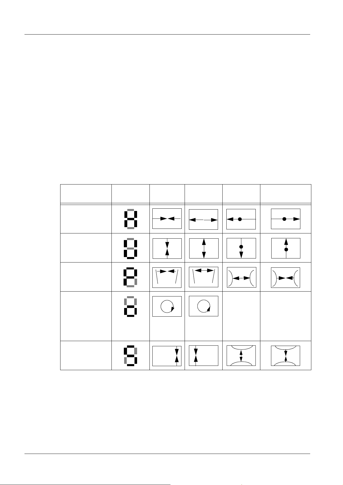
Adjustment
function
H - Geometry
V - Geometry
E / W Amplitude
Rotation
H-Parallelogram
N/S Amplitude
7-segment
display
Contrast - Contrast +
Bright-
ness -
Brightness +
Static Focus
Press Brightness + and Contrast - or + (at
same time) to
adjust focus.
• A second level can be selected by pressing the key combination contrast- and the ser-
vice key.
SIMOMED HM RA52-060.061.01.07.02 Siemens AG
07.02 TD SD 21
Page 8 of 24
Medical Solutions
Page 9

Basic Adjustments without the PC 9
• The function and operation of this level is the same as the previous level. When the ad-
justment function is selected, the 7-segment display switches between a function display and the adjustment value (off /on).
Adjustment
function
Powerdown
Ambient light
sensor
7-segment
display
Contrast - Contrast +
On Off
On Off
• Beginning with FW 1.74 (shipped since approx. middle of ’99), keyboard blocking can
be activated or deactivated by simultaneously pressing the H + and H - keys, four times
in succession.
Siemens AG RA52-060.061.01.07.02 SIMOMED HM
Medical Solutions
07.02 TD SD 21
Page 9 of 24
Page 10

10 Service User Interface
3Service User Interface
4-
Initial Installation of the Service Program 0
• Insert the supplied service diskette in the disk drive.
• Select drive A in the Windows file manager.
- Double-click on the "setup.exe" file to start the program; the installation routine will install the service software in the service window. If a service window is not yet installed, it will be installed automatically.
- Select the language (English or German), select the Continue button.
- Confirm the installation from drive A by clicking on Continue.
- Confirm installation after C:SIM_HM by clicking on Continue.
- Confirm the Service program group by clicking on Continue.
- Close the window which displays successful installation by clicking on OK.
Starting Installation of the Service Software 0
• Installation of the Service Software is started in the Windows service window by dou-
ble-clicking on the monitor symbol.
• Com 1 is selected as the default port. If a connection is not made, the Com port can be
reselected in a window which appears, or the off-line mode can be selected.
NOTE
For an explanation of the masks or of individual functions in a
mask, a help text can be selected in the masks by clicking on a
question mark button.
SIMOMED HM RA52-060.061.01.07.02 Siemens AG
07.02 TD SD 21
Page 10 of 24
Medical Solutions
Page 11

Replacing the Firmware 11
4Replacing the Firmware
5-
FW Replacement 0
• Unplug the power connector.
• The FW is located on the digital controller.
• The digital controller is located behind the
front control panel.
• Unlatch the front control panel (on both
sides) using the unlatching tool that is included in the shipment, and flip it down.
• Disconnect the ribbon cable from the digital
controller to the monitor.
• Remove the metal shielding (2 screws).
• Replace the FW.
• Installation is in the reverse order of the
steps above.
NOTE
Insert the screw inserted in plastic as follows:
Turn the screw counterclockwise until it snaps in place, only then
turn it clockwise to tighten it.
Fig. 1:
Siemens AG RA52-060.061.01.07.02 SIMOMED HM
Medical Solutions
07.02 TD SD 21
Page 11 of 24
Page 12

12 Configuration with Monitor Replacement
5Configuration with Monitor Replacement
6-
Application-relevant Configurations 0
When replacing a SIMOMED HM monitor, the following configurations must be checked in
the service software, relative to the application.
Blocking/Enabling the Front Panel Keys 0
In this window, all front panel keys that can be operated can be individually
blocked/enabled.
In the SSW, select under: => Configuration =>Lock membrane key switch
Application Setting
All (except Magic View) All front keys => ... off
Magic View
• Brightness / contrast / service => ... off
• Power => ...on
Brightness and Contrast Adjustment (Front Keys) 0
NOTE
For adjustment and selection, see: (Brightness / Contrast Adjustment using the Front but-
tons or in the SSW / p. 21).
NOTE
The video amplifier adjustment must be adjusted prior to adjusting
the brightness / contrast, see (Adjusting the Video
Amplifier / p. 18).
If an adjustment of brightness / contrast must / should be made
while the front panel keys are blocked, beginning with FW 1.74
(shipments beginning approx. mid ‘99), this can be done as follows:
By simultaneously pressing the brightness + and brightness keys 4x in sequence, key blocking can be deactivated or activated.
This means that the values can be changed without a laptop.
Power Down and Ambient Light Sensor 0
The power down mode and the ambient light sensor can be activated and deactivated in
this window. Power down & Ambient light sensor
In the SSW, select under: => Configuration =>Power down & Ambient light sensor
• Power down mode on means: if the BAS signal is missing, the monitor goes into stand-
by, and when the BAS signal is present again, the monitor switches back on.
SIMOMED HM RA52-060.061.01.07.02 Siemens AG
07.02 TD SD 21
Page 12 of 24
Medical Solutions
Page 13

Configuration with Monitor Replacement 13
• Ambient light sensor on means: if the ambient light sensor is activated, the contrast of
the monitor is readjusted according to the ambient light. Control is in the range between
the contrast setting (front control panel) and max. contrast setting in the SSW.
Application Power Down Ambient Light Sensor
All (except Magic View) off see corresponding IQAP / IQ specifications
Magic View on off
NOTE
The behavior of the ambient light sensor can be adjusted.
Adjustment is made in the SSW under: => Adjustment => Ambient
light sensor
We always use the “Default 1” values in this screen.
Norm Change Time 0
In this window, the delay time when there is a norm change can be adjusted.
Function: if the current video norm is changed, the monitor waits the time that has been
set before it starts a norm search routine and again correctly displays the new norm. If
there are instable video sources, “unwanted” norm changes and image flicker can be prevented by extending the norm change time.
In the SSW, select under: => Configuration => Scan Update time
Size / position and 1:1 / 3:4 format relative to the application. 0
Size / Position
NOTE
1:1 / 3:4 Format
In this window, the format musts be manually configured to 1:1 or 3:4 for certain applications (see the list - blocked Norm). Manual selection is required because the monitor
cannot detect the format from the video signal.
In the SSW, select under: => Configuration=> Disable Scan
Siemens AG RA52-060.061.01.07.02 SIMOMED HM
Medical Solutions
The size / position must be adjusted under => Adjustment => Geometry
correctly displayed.
It must be ensured that a square is also displayed square.
Example, SMPTE test pattern:
The 5 horizontal boxes must have the same display length as the
5 vertical boxes on the screen (measure using a ruler, etc.).
Page 13 of 24
07.02 TD SD 21
Page 14

14 Configuration with Monitor Replacement
System Norm Used Blocked Norm (black background)
Hicor / ACOM 50Hz Norm 12 (1249
lines/100Hz/4:3)
HICOR / ACOM 60Hz Norm 8 (1023
lines/120Hz/4:3)
HICOR 50Hz Bypass (!) Norm 5 (1249
lines/50Hz/1:1)
HICOR 60 Hz Bypass (!) Norm 1 (1023
lines/60Hz/1:1)
Multistory TOP
Neurotic TOP
Norm 10 (2251
lines/120Hz/3:4)
AngiostarTOP
MST TOP / NST TOP /
AST TOP
Norm 3 (1125
lines/60Hz/1:1)
=> in Bypass (!)
Fluorospot TOP 1K
AXIOM Artis ....
Norm 2 (1066
lines/72Hz/5:4)
Fluorospot TOP 2K Norm 9 (1066
lines/76Hz/5:4)
Norm 11(2497 lines/100Hz/1:1)
Norm 7 (2045Hz/120Hz/1:1)
n.a.
n.a.
n.a.
n.a.
n.a.
n.a.
Fluorospot TOP Bootup
(!)
Norm 1 (1023
lines/60Hz/1:1)
Fluorospot Compact Norm 2 (1066
lines/72Hz/5:4)
Leonardo Norm 2 (1066
lines/72Hz/5:4)
Fluorospot H 50Hz Norm 5 (1249
lines/50Hz/1:1)
Fluorospot H 60Hz Norm 1 (1023
lines/60Hz/1:1)
Multistar KK without
display 2000 50Hz
Multistar KK without
display 2000 60Hz
Multistar KK with
display 2000 50Hz
Norm 5 (1249
lines/50Hz/1:1)
Norm 1 (1023
lines/60Hz/1:1)
Norm 1 (12497
lines/100Hz/1:1)
n.a.
n.a.
n.a.
n.a.
n.a.
n.a.
n.a.
Norm 12 (1249 lines/100Hz/4:3)
SIMOMED HM RA52-060.061.01.07.02 Siemens AG
07.02 TD SD 21
Page 14 of 24
Medical Solutions
Page 15

Configuration with Monitor Replacement 15
System Norm Used Blocked Norm (black background)
Multistar KK with
display 2000 60Hz
AXIOM Artis Bypass (!) Norm 3 (1125
Norm 7 (2045
lines/120Hz/1:1)
lines/60Hz/1:1)
Norm 8 (1023 lines/120Hz/4:3)
n.a.
Jumper Configuration (Hardware) 0
NOTE
Jumpers for Monitor Size
Behind the front plane, on the digital
controller, there are two jumpers:
• X11 => configuration of the monitor
size. Incorrect configuration leads to
the error: EEPROM (in this case, reposition the jumper).
If one of the jumper positions described below is changed, the
monitor must be disconnected from line power!
- 1 installed => 44cm (17”)
- not installed => 54cm (21”)
Fig. 2: Monitor size
• X8 => Sensitivity of the ambient light
sensor (factory setting, 2-3 middle).
Video Terminal Resistor / Cable Compensator
• Remove the rear wall of the housing
Remove the 2 screws on the rear wall, take
the housing off towards the back.
Fig. 3:
• Remove the top cover panel.
Siemens AG RA52-060.061.01.07.02 SIMOMED HM
Medical Solutions
07.02 TD SD 21
Page 15 of 24
Page 16

16 Configuration with Monitor Replacement
Remove the 9 screws, remove the top cover
panel.
Fig. 4:
• Remove the rear cover panel.
Remove the 7 screws, remove the rear cover
panel.
• Jumper positions.
Fig. 5:
SIMOMED HM RA52-060.061.01.07.02 Siemens AG
07.02 TD SD 21
Page 16 of 24
Medical Solutions
Page 17

Configuration with Monitor Replacement 17
The terminal resistors for the inputs on
the video amplifier can be changed using
jumpers.
• X4 => BAS input terminal resistor.
- 1- 2 => ON
- 2-3 => OFF
- Standard (setting when shipped)
ON
• X5 => H- Synch input terminal resis-
tor.
- 1- 2 => ON
- 2- 3 => OFF
- Standard (setting when shipped)
OFF
• S1 cable compensator.
- 1 => ON
- 2 => OFF
- Standard (setting when shipped)
OFF
Fig. 6: Video terminal resistor / cable
compensator
Installation of the cover panels is in the reverse of the above instructions.
Siemens AG RA52-060.061.01.07.02 SIMOMED HM
Medical Solutions
07.02 TD SD 21
Page 17 of 24
Page 18

18 Adjusting the Max. Brightness/Contrast
6Adjusting the Max. Brightness/Contrast
7-
Adjusting the Video Amplifier 0
General Remarks 0
• The maximum brightness and the maximum contrast are adjusted in the window (Ad-
justment => Video Amplifier). Adjustment can be made to these set values using the
front control knobs (brightness/contrast) or by means of the ambient light sensor, when
activated.
• The settings are always performed in the 0% field for brightness and in the 100% field
for contrast. The exception is with Magic View; see the value table.
• Test image
- AXIOM Artis ......
We use the “Siemens” test pattern (it has larger measuring fields than the SMPTE
test pattern).for H/C adjustment.
Select zoom to magnify the fields again. Move the corresponding field (0% - 100%) to
approx. the center of the image. Note: The hand symbol may not be in the measuring
field (incorrect measurement)!
Important:
The window for the test pattern must always be fully opened in AXIOM ARTIS.. If the
window values are/were changed, the “Patient” closed, the “new” values are saved!
Open values:
WC 2048
WW 4094
- The adjustment can be performed with the test image for the particular digital system
or with the monitor multinorm test box. If the test box is used, pay attention to the correct “Norm” as well as to the BAS values!
- HICOR / ACOM
If the SMPTE test pattern is used, the test point for the black value is at the right edge
of the screen, outside the SMPTE test image.
- Multistar TOP
Use the black / white test image.
- Multistar KK
If the SMPTE test pattern is used, the zoom function must be used to obtain a
sufficiently large black area for the measurement.
- Monitor Mulitnorm Testbox.
In the list box, the corresponding system (e.g. HICOR, ... ) must be selected.
The black/white test image must be used for the adjustment.
If HICOR is selected (also general) pay attention to the video level: change the
B-signal to 650mV and the A-signal to 50mV (with 1V BAS).
• Warm-up phase
- The monitor must be left on for at least 20 minutes (warm-up behavior of the picture
tube). If the time is too brief, it will not be possible to make a selection in the screen.
SIMOMED HM RA52-060.061.01.07.02 Siemens AG
07.02 TD SD 21
Page 18 of 24
Medical Solutions
Page 19

Adjusting the Max. Brightness/Contrast 19
Adjustment 0
NOTE
NOTE
Adjustment sequence:
The basic setting must have been performed!
The brightness / contrast adjustment is performed using the front
buttons or in the SSW.
The bypass adjustment must be performed only if the “emergency
mode” and thus generally for a different norm for the “normal
mode”
Ambient light sensor:
The ambient light sensor is switched off automatically by the SW
when the window is opened for the adjustment of the brightness /
contrast basic setting and for bypass.
When "Brightness / Contrast Adjustment using the front buttons
or in the SSW" is performed, the ambient light sensor must be
switched off in => Configuration => Power down & Ambient light
sensor.
Siemens AG RA52-060.061.01.07.02 SIMOMED HM
Medical Solutions
07.02 TD SD 21
Page 19 of 24
Page 20

20 Adjusting the Max. Brightness/Contrast
1
3
2
4
5
6
Brightness / Contrast Basic Setting
• The monitor must be on for at least 20
minutes"
• Select the test pattern for the particular
system.
• Select the “Adjustment video amplifier”
window in the SSW under:
=> Adjustment => Video amplifier
• Select the Cutoff‘s button (cutoff is per-
formed).
• Select the Max. Background button. Us-
ing the slider for maximum background,
set the value from the table (Tab.3/p.22)
for Max. Background.
Note: A dark monitor image is generated
by selecting the button.
• Select the Max. Contrast button.
- Using the slider for Maximum Contrast,
set the value for Max. Contrast in the
100% white field from the table
(Tab.3/p.22).
Fig. 7: Adjustment Brightness/Contrast
Pos. 1 Button for Cutoff
Pos. 2 Button and slider for max. Background
Pos. 3 Button for Contrast adjustment
Pos. 4 Slider for maximum Contrast adjustment
Pos. 5 Slider for Brightness adjustment
Pos. 6 Button for Contrast adjustment
- Using the Brightness slider, set the value for Max. Brightness in the 0% field
from the table (Tab.3/p.22).
- If necessary, repeat both adjustments.
SIMOMED HM RA52-060.061.01.07.02 Siemens AG
07.02 TD SD 21
Page 20 of 24
Medical Solutions
Page 21

Adjusting the Max. Brightness/Contrast 21
Brightness / Contrast Adjustment using the Front buttons or in the SSW
Tab. 1 Front buttons
• Using the front buttons, or if if the
front buttons are blocked, in the SSW
under:
=> Configuration => Brightness and
Contrast
the final brightness / contrast values
are adjusted. For the current values,
see the applicable IQAP/IQ.
- Set the Contrast minimum slider to
0 (not used).
- Using the slider for Maximum background, set the value for brightness from the table (Tab. 3 / p. 22).
- Using the slider for Maximum contrast, set the value for contrast from
the table (Tab.3/p.22).
- If necessary,repeat both adjustments.
Bypass Adjustment
Tab. 2 Bypass
• If a bypass mode is being used at the par-
ticular system (as a rule, this is the emergency mode), the brightness / contrast
values for this mode must be adapted to
the “Normal mode”.
This is done in the SSW under:
Fig. 8: int. Brightness / Contrast
=> Adjustment => Video amplifier => Bypass
- Insert the TV dynamic test.
Fig. 9: Bypass Window
In the “Normal mode”, measure the luminous intensity values in the 2L and 5R
fields using the Mavo monitor and make
a note of the values.
- In the “Bypass mode”, use the slider for
Maximum background to set the value in
the 5R field and the slider for Maximum
contrast to set the value in the 2L field to
the values that were noted.
- If necessary, repeat both adjustments.
Siemens AG RA52-060.061.01.07.02 SIMOMED HM
Medical Solutions
07.02 TD SD 21
Page 21 of 24
Page 22

22 Adjusting the Max. Brightness/Contrast
Table for H/C Values
NOTE
Tab. 3 B/C Value
System
Important: see
1
Card Systems (prior
to AXIOM)
ACOM
Important: see
1
Multispot TOP
Adjust the values that have been set.
The gradations, 5% in the 0% field, as well as 95% in the 100% field
must be visible; if necessary, use the complete tolerance range!
Brightness / Contrast
Max.
Back-
max. Contrast
Adjustment using the
front buttons or in the
SSW
ground
(cd/m
2
)
Max.
Contrast
( cd/m
2
)
Max.
Brightness
( cd/m2)
Contrast (
2
cd/m
)
Brightness
( cd/m2)
3 ± 0,3 560 ± 30 1 ± 0,2 500 ± 20 0,8 ± 0,1
Neurostar TOP
3 ± 0,3 560 ± 30 1 ± 0,2 400 ± 20 0,5 ± 0,15
Angiostar TOP
Multistar KK
Polystar TOP
Fluorospot H Systems
Fluorospot TOP
3 ± 0,3 400 ± 20 1 ± 0,1 260 ± 10 0,5 ± 0,15
(1k/2k)
Fluorospot Compact
AXIOM Artis MP
Magic VIEW
=> in the 90% or
3 ± 0,3 229 ± 5 9 ± 0,5 229 ± 5 9 ± 0,5
20% field of the
SMPTE test pattern!
Leonardo (WS) 3±0,3 560 ± 30 1 ± 0,1 260 ± 10 0,5 ± 0,15
AXIOM Artis
3 ± 0,3 450 ± 20 1 ± 0,1 400 ± 20 0,5 ± 0,1
FA / FC / BA / BC
1. The monitor with Part No. 74 11 726 is not used in this application (max. luminous intensity
= 450 cd/m2)
SIMOMED HM RA52-060.061.01.07.02 Siemens AG
07.02 TD SD 21
Page 22 of 24
Medical Solutions
Page 23

Changes to Previous Version 23
7Changes to Previous Version
8-
General Remarks Warning notes expanded.
Adjustment of max. brightness / contrast Adjustment / Configuration
expanded.
Siemens AG RA52-060.061.01.07.02 SIMOMED HM
Medical Solutions
07.02 TD SD 21
Page 23 of 24
Page 24

24 Changes to Previous Version
SIMOMED HM RA52-060.061.01.07.02 Siemens AG
07.02 TD SD 21
Page 24 of 24
Medical Solutions
 Loading...