

Page 1

SIMOMED
Service Instructions
SP
Monitor 44 cm
100/120 Hz
11 02 628 X2080 625/525 lines From serial no. 02593
60 Hz
11 02 917 X2079 525 lines From serial no. 01188
© Siemens AG 1995
The reproduction, transmission or
use of this docu men t or its con tent s
is not permitted without express
written authority. Offenders will be
liable for damages. All rights,
including rights created by patent
grant or registration of a utility
model _or_ design,_are_ reserved.
English
Print No.: RX52-060.061.02.04.02 Doc . Gen. Date: 11.00
Replaces: RX52-060.061.02.03.02
Page 2

0 - 2 Revision
Chapter Page Revision
0all04
1all04
2all04
3all04
4all04
5all04
6all04
7all04
8all04
9all04
SIMOMED RX52-060.061.02 Page 2 of 4 Siemens AG
Rev. 04 11.00 TD PS 24 Medical Engineering
Page 3

Contents 0 - 3
Page
1 _______General information ____________________________________________ 1 -1
General information . . . . . . . . . . . . . . . . . . . . . . . . . . . . . . . . . . . 1 -1
Service . . . . . . . . . . . . . . . . . . . . . . . . . . . . . . . . . . . . . . . . . 1 -1
Safety information . . . . . . . . . . . . . . . . . . . . . . . . . . . . . . . . . . . . 1 -2
Maintenance. . . . . . . . . . . . . . . . . . . . . . . . . . . . . . . . . . . . . . . 1 -3
Required documents . . . . . . . . . . . . . . . . . . . . . . . . . . . . . . . . . . 1 -3
Measuring instruments and auxilia ry devices . . . . . . . . . . . . . . . . . . . . . . 1 -4
Removing the PC boards . . . . . . . . . . . . . . . . . . . . . . . . . . . . . . . . 1 -5
Removing the control panel . . . . . . . . . . . . . . . . . . . . . . . . . . . . . . . 1 -5
Removing the picture tube . . . . . . . . . . . . . . . . . . . . . . . . . . . . . . . 1 -6
Installing the picture tube . . . . . . . . . . . . . . . . . . . . . . . . . . . . . . . . 1 -6
2 _______Test patterns __________________________________________________ 2 -1
Test patterns for X-ray systems with MEMOSKOP 3/50/SUB. . . . . . . . . . . . . . 2 -1
Activating the service set-u p mode. . . . . . . . . . . . . . . . . . . . . . . . . . 2 -1
Exiting the SETUP Mode . . . . . . . . . . . . . . . . . . . . . . . . . . . . . . 2 -1
Test patterns of the Memoskop 3 / 50 / 100 . . . . . . . . . . . . . . . . . . . . . 2 -2
Test patterns for X-ray systems with Memoskop C/C-E. . . . . . . . . . . . . . . . . 2 -3
Test patterns in X-ray systems with VIDEOMED D only . . . . . . . . . . . . . . . . 2 -5
Test patterns for Videomed D . . . . . . . . . . . . . . . . . . . . . . . . . . . . 2 -5
Using the monit o r m u lt in o rm te s t b o x . . . . . . . . . . . . . . . . . . . . . . . . . . 2 -7
Selection of test patterns on the SIREMOBIL 2000. . . . . . . . . . . . . . . . . . . 2 -8
Stored test patterns . . . . . . . . . . . . . . . . . . . . . . . . . . . . . . . . . 2 -8
test patterns (= camera test patterns) . . . . . . . . . . . . . . . . . . . . . . 2 -8
TV
3 _______Operating voltages _____________________________________________ 3 -1
Changing over the supply voltage on power pack board SV1.2. . . . . . . . . . . . . 3 -1
Changing over the supply voltage from 230 V to 115 V . . . . . . . . . . . . . . . 3 -1
Checking the voltages on sweep board AP1.1 / AP1.4 . . . . . . . . . . . . . . . . . 3 -2
4 _______Sweep board __________________________________________________ 4 -1
Setting the horizontal sweep to 525 lines / 60 and 120 Hz . . . . . . . . . . . . . . . 4 -1
Setting the vertical sweep to 525 lines / 60 and 120 Hz. . . . . . . . . . . . . . . . . 4 -3
Setting the horizontal sweep to 625 lines / 100 Hz . . . . . . . . . . . . . . . . . . . 4 -4
Setting the vertical sweep to 625 lines/100Hz. . . . . . . . . . . . . . . . . . . . . . 4 -6
Checking / set ting the focus . . . . . . . . . . . . . . . . . . . . . . . . . . . . . . . 4 -7
Checking the high voltage cut-off operation. . . . . . . . . . . . . . . . . . . . . . . 4 -8
5 _______Front controls _________________________________________________ 5 -1
Preparation for setting the brightness and contrast . . . . . . . . . . . . . . . . . . . 5 -1
Brightness and contrast with the "vertical beam" test pattern. . . . . . . . . . . . . . 5 -2
Brightness and contrast with the "square" test pattern . . . . . . . . . . . . . . . . . 5 -3
Siemens AG RX52-060.061.02 Page 3 of 4 SIMOMED
Medical Engineering Rev. 04 11.00 TD PS 24
Page 4

0 - 4 Contents
Page
6 ______ Video amplifier board VV ________________________________________ 6 -1
Luminance / Preparations . . . . . . . . . . . . . . . . . . . . . . . . . . . . . . . .6 -1
Checking the luminance of the picture tube . . . . . . . . . . . . . . . . . . . . . . .6 -1
Adjusting the video amplifier . . . . . . . . . . . . . . . . . . . . . . . . . . . . .6 -1
Luminance and gain . . . . . . . . . . . . . . . . . . . . . . . . . . . . . . . . . . .6 -3
Sensor setting . . . . . . . . . . . . . . . . . . . . . . . . . . . . . . . . . . . . . .6 -6
7 ______ Protective ground wire insulation strength check____________________ 7 -1
8 ______ Changes as compa red to previous ve rsion _____________________ ____ 8 -1
9 ______ Appendix - Test templates _______________________________________ 9 -1
SIMOMED RX52-060.061.02 Page 4 of 4 Siemens AG
Rev. 04 11.00 TD PS 24 Medical Engineering
Page 5

General information 1
General information 1
Before starting work, make sure that the part number of the monitor corresponds with the
number of the instructions.
• Type X2080 monitors can be operated at 100 and 120 Hz and type X2079 at
50/60 Hz without changing the video standard.
Voltage: when delivered = 230 V +10% / -15%
(can be switched to 115V+10% / -15%).
• The monitor is adjusted wi th a functioning Memoskop. If this is no t available, the test
pattern of the Multinorm tes t box (refer to "Measuring inst ruments and auxiliary
devices"), the corresponding digital system, or the Videomed D can be used, if
necessary.
• Except for the luminance, adjustments are required only aft er replacing a module or
picture tube.
1 - 1
• The maximum luminance influences t he image quality to a considerable ex tent. If after a
lengthy operating time, t he luminance does not attain a maximum of
replace the picture tube.
> 300 cd/m
2
,
• When adjusting luminance, che ck the luminance of the second monitor as well.
Service 1
Repairs are limited to replacing modules.
Individual parts for PC boards are not avail able.
Parts available for delivery are shown in the spare parts list.
• Test templates are inc luded in the appendix. Their purpose i s to simplify service. The test
template is fastened onto the picture tube to adjust the image geometry. If the image
geometry is correctly adjusted, t he intersections of the grid li nes must be located within
the rings. Otherwise, adjust the imag e geometry in accordance with Chap. 4.
Siemens AG RX52-060.061.02 Page 1 of 12 SIMOMED
Medical Engineering Rev. 04 11.00 TD PS 24
Page 6

1 - 2 General information
CAUTION
Safety information 1
Re: DHHS requirements
• DHHS requirements are met via factor y adjustment of the PC boards.
- Do not replace components or make circuit modif ications on the PC boards.
Always replace PC boards when servici ng the system.
- After replacing the power pack board SV1, check the voltage U = 48 V
TP “9”.
Ensure compliance with the tolerances.
This ensures compliance with DHHS requirements.
• Protection: IEC 601, protection class I, (with protective conductor)
unit type B IP 20 with reinforced insulati on for
primary/secondary (4 kV).
± 0.5 V at
• Interference
suppression:
acc. to VDE 0871, Part 2, limit value B,
acc. to VDE 0871, Part 3, interference suppression grade N,
• Comply with the safety-t echnical information in TI 236 “Safety regulations for installa tion
and maintenance.”
• Check that the monitor mounti ng and hardware are secure and show no signs of
damage.
Disconnect the power plug before removing the cover. Electric
shock hazard exists when the unit is still connected.
Observe the safety instructions accordi ng to theTI folder Register 2 (replaced by ARTD,
Part 2, ARTD-002.731.12.01) due to the risk of implosion of the picture tube.
When handling PC boards, observe the ESD directives according to TI 219.
To comply with EMC regulations, ensure that shielding plates for the PC boards are
mounted correctly.
After completing all work and attaching the hood, test the protective conductor according
to TI 236, document number RA0-000.12.20... (replaced by ARTD, Part 2,
ARTD-002.731.17.01)
SIMOMED RX52-060.061.02 Page 2 of 12 Siemens AG
Rev. 04 11.00 TD PS 24 Medical Engineering
Page 7

General information 1 - 3
Maintenance 1
• The picture tube parameters change with increasing time of operation. Thi s affects the
luminance and the brightness and/or the cont rast setting. For this reason, t he luminance
has to be tested every 12 months according to chapter 6-1 and, if necessary, the vide o
amplifier setting has to be perfor med according to pages 5-1 through 6-5.
• The inner part of the monitor should be cleaned with compressed air f rom time to time
depending on the amount of dust in the operating r ooms.
In order to recognize parameter devi ations, the image quality test for the specific system
must be performed every 12 months according to the IQ i nstructions.
If deviations in sharpness and geometry ar e found, correct them according to t he service
instructions.
Required documents 1
- Operating instructions for the X- ray system to which the SIMOMED monitor is
connected.
- Wiring diagrams of the corresponding SIMOMED, type X2079 or X208 0
- IQ Instructions for the X-ray system used.
- Operating Instructions for the Moni tor-Multinorm Testbox (included with the uni t)
- Operating Instructions for the Mavo- Monitor (included with the unit)
- Safety-technical Instruc tions. RA0-000.012.20... and the inst ructions
“Handling of vacuum container” TI 201 from TI-fol der part 2, replaced by ARTD,
Part 2, ARTD-002.731.12.01.
- Spare parts list RA 52-060.081...
Siemens AG RX52-060.061.02 Page 3 of 12 SIMOMED
Medical Engineering Rev. 04 11.00 TD PS 24
Page 8

1 - 4 General information
Measuring instruments and auxiliary devices 1
• Oscilloscope, 100 MHz
• Probe 10 :1
• Digital multimeter , e.g. Fluke 8060A
• Monitor Multinorm Te stbox 97 16 754 Y4905 (only if MEMOSKOP 2000 with keyboard is
not available)
• High-voltage probe 1 GΩ ( 1000 :1)
• MEMOSKOP keyboard (part of X-ray system)
• Mavomonitor luminance measuri ng instrument (direct order, see ARTD, group TD36)
• Protective conductor test er, 44 15 899 RV090
• TORX offset screwdriver ki t 99 00 663 GE999
• Auxiliary tool (serv ice key, included with the monitor)
- for unlocking the control console
- for adjusting the contrast control on the monitor
- for adjusting the brightness control on the monitor.
Key for adjusting the potentiometers on the boards
(hexagon)
Separation
point
Key for brightness and contrast controls on the control console
Attachment for unlocking the control console on the monitor
SIMOMED RX52-060.061.02 Page 4 of 12 Siemens AG
Rev. 04 11.00 TD PS 24 Medical Engineering
Page 9

General information 1 - 5
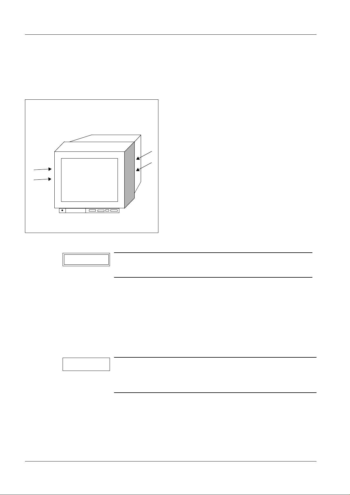
Fig. 1
Removing the PC boards 1
• Remove the two back mounting screws on the monitor housing.
• Remove the housing.
• Remove the two screws on the rear cover plate.
• Swing the cover plate to one side and r emove it.
• Remove the three remainin g screws and remove the top cover plate.
• Remove the cover from above the v ideo connections (3 screws).
• Remove the bottom mounting screw on the lef t-hand SV board (power pack board).
• Remove the center mounting sc rew on the right-hand AP board (sweep board).
• Take out the two boards and hook them onto the supports provided from the outside with
the plastic pins, ensuring that t he components face inward.
• Loosen the screw and pull out t he video amplifier board and hook it into the l ocking
position required.
Removing the control panel 1
• Use the plastic service key pac ked with the monitor.
• Push the service key to ngue from underneath into the slots provi ded on the left and right
of the control panel (
↑/Fig. 1) and disengage the control panel.
Siemens AG RX52-060.061.02 Page 5 of 12 SIMOMED
Medical Engineering Rev. 04 11.00 TD PS 24
Page 10
1 - 6 General information
disengage
CAUTION
NOTICE
Removing the picture tube 1
(including sweep unit 1))
• Remove the PC boards and the control pane l as described above.
• Disengage the front frame of the picture tube by slightly pul ling the right and left side
panels apart and removing the frame toward the f ront.
From the picture tube, remove the
• base board connection
• neck shielding plat e connection
• ground connection of the picture tube outer
covering
• sweep unit connection
• high-voltage clip
• Loosen the picture tube and the sweep uni t
1)
The sweep unit should remain on the picture tube.
2)
Do not adjust the (hexagonal) spacer nuts since they have
been adjusted in the factory.
1)
with the four slotted screws on the front2).
• Pull the picture tub e back slightly.
• Loosen the two flat plugs of the antistatic connection.
• Remove the entire pict ure tube after taking out the 4 scr ews.
Installing the picture tube 1
• Reinstall the picture t ube according to the above instruct ions (in reverse order) an d
connect it.
• Check the flat plugs of the anti static connections for proper
contact; otherwise, there is a risk of elect ric shock.
• After reconnecting, ad apt the video amplifier (VV board) to the
new picture tube as described on page 6-1.
SIMOMED RX52-060.061.02 Page 6 of 12 Siemens AG
Rev. 04 11.00 TD PS 24 Medical Engineering
Page 11
General information 1 - 7
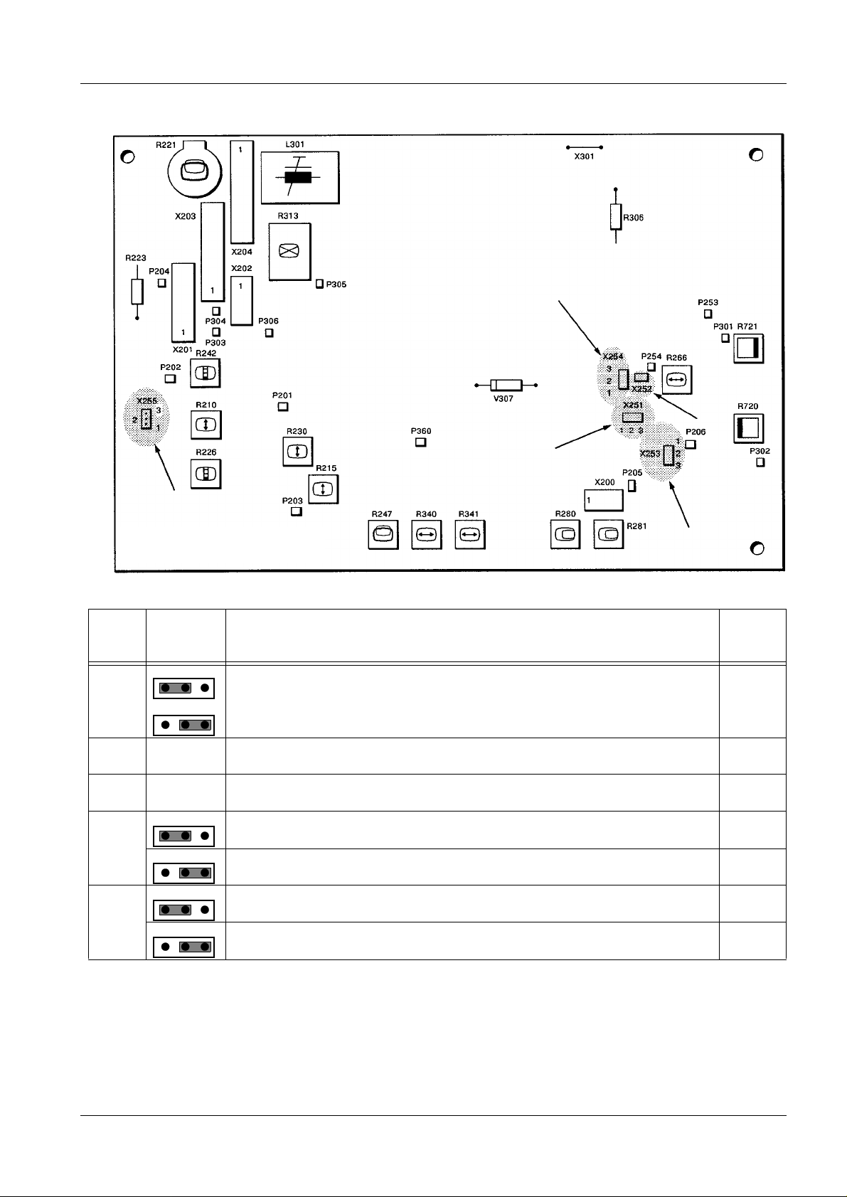
Sweep board AP1.1/AP1.4
Component side
Jumper coding on the sweep board
Preset
C79145-A3058-D913
X251 Mute = synchronization-dependent standby; not used here
1 2 3
1
2 3
not used X
X252 1-2 f
-adjustment; only closed during adjustment open
H
X253 open With board C79145-A3058-D913 open open
X254 Normal operation
1 2 3
1 2
3
Video recorder operation X
X255 100/120 Hz or 50/60 Hz automatic standard switchover enabled X
1 2 3
1 2 3
Standard switchover 100 or 50 Hz fixed
Siemens AG RX52-060.061.02 Page 7 of 12 SIMOMED
Medical Engineering Rev. 04 11.00 TD PS 24
Page 12
1 - 8 General information
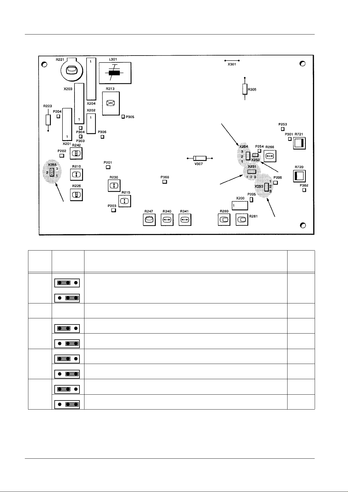
Sweep board AP1.1/AP1.4
Component side
Jumper coding on the sweep board
Preset
C79145-A3058-D915
X251 Mute = synchronization-dependent standby; not used here
1 2 3
1
2 3
not used X
X252 1-2 f
1 2 3
-adjustment; only closed during adjustment open
H
X253 Clamping ON X
1 2 3
Clamping OFF
1 2
3
X254 Normal operation
1 2 3
Video recorder operatio n X
X255 100/120 Hz or 50/60 Hz automatic standard switchover enabled X
1 2 3
1 2
3
Standard switchover 100 or 50 Hz fixed
SIMOMED RX52-060.061.02 Page 8 of 12 Siemens AG
Rev. 04 11.00 TD PS 24 Medical Engineering
Page 13
General information 1 - 9
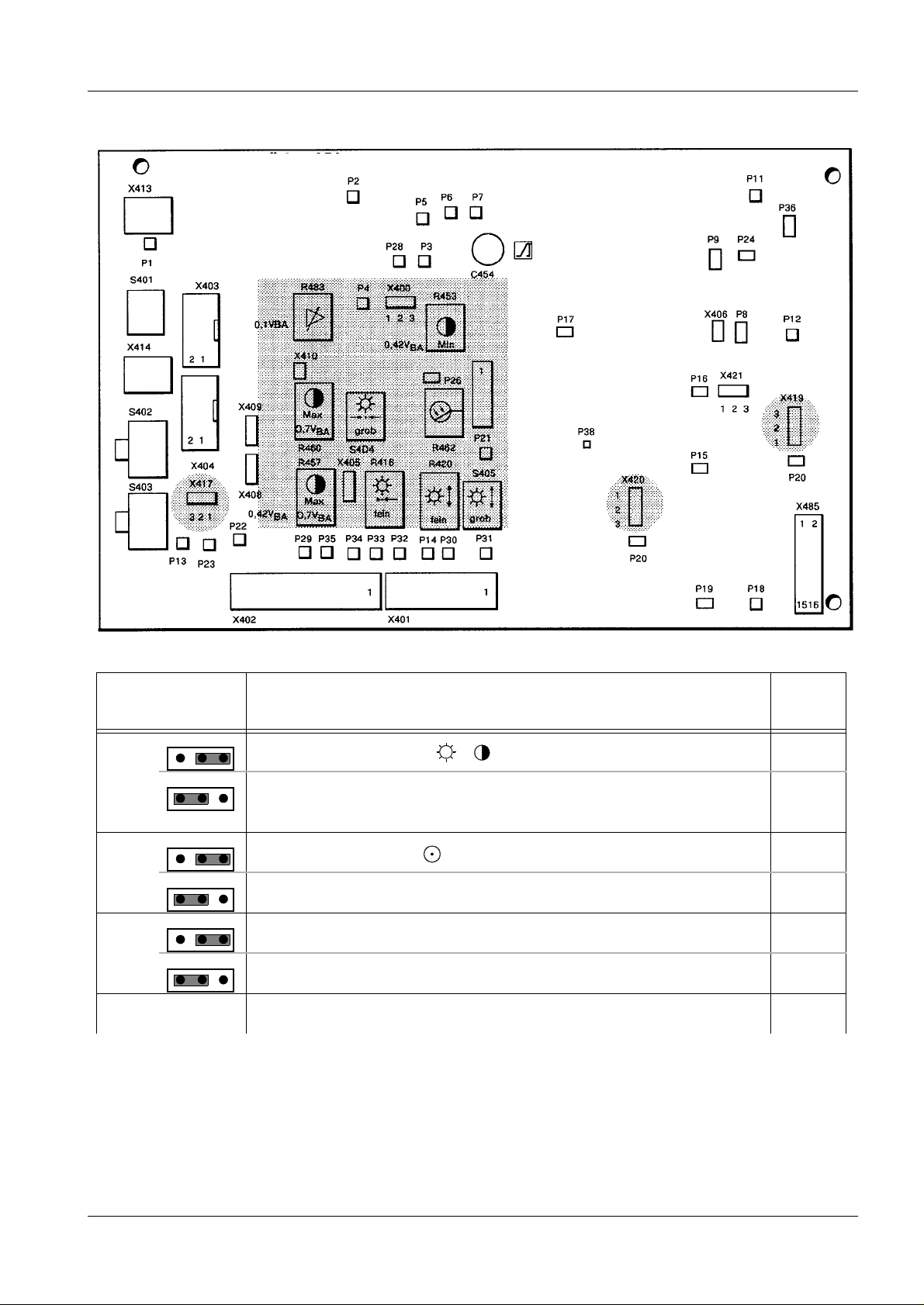
Video amplifier VV
Component side
Jumper coding on the video amplifier for Monitor
Preset
11 02 917 X2079 (50/60 Hz)
X417 Only external or internal / operation X
3 2 1
1
2
3
External or internal sel ection via r emote control swi tch on the mo nitor
(option)
3
2 1
X419 Room lighting sensor " “ X
3 2 1
Room lighting sensor “SERVICE”
X420 Brightness “fine” (range 4 - 7 V)
3 2 1
3
2 1
Brightness “coarse” (range 0 - 10 V) X
continued on page 1-10
Siemens AG RX52-060.061.02 Page 9 of 12 SIMOMED
Medical Engineering Rev. 04 11.00 TD PS 24
Page 14

1 - 10 General information
Video amplifier VV
Component side
Jumper coding on the video amplifier for Monitor
Preset
11 02 917 X2079 (50/60 Hz)
X421 Contrast “fine” (range 4 - 7 V)
1 2 3
1
2
3
Contrast “coarse” (range 0 - 10 V) X
S402 1 Video ground isolated from protective conductor X
2 Video ground connected to protective conductor
S403 1 Internal / setting for additional monitors
1
2
3
External / setting in the monitor looped through
S401 1 no 75
75
Ω termination (video signal is forwarded)
75
Ω termination (video signal is not forwarded) X
2 without black level clamping
with black level clamping X
3 Gain “High”
Gain “Low” X
4 Room lighting sensor disabled
Room lighting sensor enabled X
SIMOMED RX52-060.061.02 Page 10 of 12 Siemens AG
Rev. 04 11.00 TD PS 24 Medical Engineering
Page 15

General information 1 - 11
Video amplifier VV
Component side
Jumper coding on the video amplifier for Monitor
Preset
11 02 628 X2080 (100/ 120 Hz)
X417 Only external or internal / operation X
3 2 1
1
2
3
External or internal sel ection via r emote control swi tch on the mo nitor
(option)
3
2 1
X419 Room lighting sensor " “ X
3 2 1
Room lighting sensor “SERVICE”
X420 Brightness “fine” (range 4 - 7 V)
3 2 1
3
2 1
Brightness “coarse” (range 0 - 10 V) X
continued on page 1-12
Siemens AG RX52-060.061.02 Page 1 1 of 12 SIMOMED
Medical Engineering Rev. 04 11.00 TD PS 24
Page 16

1 - 12 General information
Video amplifier VV
Component side
Jumper coding on the video amplifier for Monitor
Preset
11 02 628 X2080 (100/ 120 Hz)
X421 Contrast “fine” (range 4 - 7 V)
1 2 3
1
2
3
Contrast “coarse” (range 0 - 10 V) X
S402 1 Video without protective conduc tor X
2 Video with protective conducto r
S403 1 Internal / setting for additional monitors
1
2
3
External / setting in the monitor looped through
S401 1 no 75
75
Ω termination (video signal is forwarded)
75
Ω termination (video signal is not forwarded) X
2 without black level clamping
with black level clamping X
3 Gain “High” X
Gain “Low”
4 Room lighting sensor disabled
Room lighting sensor enabled X
SIMOMED RX52-060.061.02 Page 12 of 12 Siemens AG
Rev. 04 11.00 TD PS 24 Medical Engineering
Page 17

NOTICE
Test patterns 2
Test patterns for X-ray systems with MEMOSKOP 3/50/SUB 2
Test patterns for the setting instructions and inspection of the monitor are selected with
the MEMOSKOP keyboard.
If the keyboard, part no. 1102609, is not insta ll ed, it will be included for service in the
delivery of the X-ray system.
- For this purpose, the keyboard has to be c onnected to the MEMOSKOP for service.
- Switch off the system.
- Remove the EMC cable shielding plate from the Memoskop.
- Connect the keyboard on plug panel ”X5”.
- Switch on the system.
The following procedure is the same for systems wit h int egrated and service keyboards.
Activating the servic e set-up mode. 2
• Switch on the system and wait until the MEMOSKOP warms up.
<X> means press the key on the keyboard.
<CTRL>+<E> means press both buttons at the same time.
2 - 1
• Press the following keys on the MEMOSKOP keyb oard one after another:
SHIFT SHIFT CTRL
++ +
NEXT
PAT
After the set-up mode is acti vated, a ser ies of numbers wi ll be di splayed on the lower par t
of the screen. The test patterns can only be called up if the numbers are overwr itten.
Enter the numbers without blanks.
Make sure that you enter the correct numbers in order to avoid a system crash.
- Numbers printed in boldface type change t he test pattern.
- To enter a new test pattern after t he numbers have been changed, always press
<CTRL>+<E> .
It will then take approx. 20 seconds bef ore the test pattern appears on the monitor .
Test patterns
SMPTE-similar 0000 8808 0A0303C F00
Gray notch horizontal 0000 8808 0A03021 C00
Black-white transition 0000 8808 0A03023 C00
Gray scale 0% - 100% (exponential) 0000 8808 0A03025 C00
Gray scale 0% - 100% (linear) 0000 8808 0A03026 C00
Black 0% 0000 8808 0A03027 C00
Ver ti cal white bar 60% 0000 8808 0A03028 C00
@
%
S
• (After changing the test pat tern code press <CTRL>+<E>).
Exiting the SETUP Mode 2
• After switching on and of f, the memory returns to normal operat ion.
Siemens AG RX52-060.061.02 Page 1 of 8 SIMOMED
Medical Engineering Rev. 04 11.00 TD PS 24
Page 18

2 - 2 Test patterns
Fig.1.4
exponential
0%
100%
0,5 cd/m
2
Test patterns of the Memoskop 3 / 50 / 100 2
Fig. 1 Fig. 2
linear
Fig. 3 Fig. 4
0%
100%
Fig.1.5
Fig. 5 Fig. 6
SIMOMED RX52-060.061.02 Page 2 of 8 Siemens AG
Rev. 04 11.00 TD PS 24 Medical Engineering
0,5 cd/m
2
Page 19

Test patterns 2 - 3
Test patterns for X-ray systems with Memoskop C/C-E 2
Use the keyboard of the Memoskop C/CE to select test patterns in accordance with the
setting instructions.
If there is no keyboard connected, the test patterns can be called up with the service PC
(refer to the service instructions). To display the test patterns across the entire monitor
screen, "circle mask enabled" can be temporarily progr ammed to "no".
• Call up technical Setup ( simultaneously press the CTRL + T keys).
• Follow the menu guidance on t he system monitor.
• Call up "Circle mask setu p" and set "Circle mask enable" to "No" in the submenu.
• Call up "Test patt ern generation" .
• Select the desired test patt ern in the submenu and acknowledge by pressing the Retur n
key.
• Select 4 and acknowledge with t he Return key.
• Press the Home key 2 x to clear the menu text.
• After completing the adjust ment, set "Circle mask enable" back to "Yes ".
L I H
Fig. 7 square > VA00B
also available in SW version ... of Memoskop C/C-E
12.03.97
1
Fig. 8 SMPTE test pattern
Siemens AG RX52-060.061.02 Page 3 of 8 SIMOMED
Medical Engineering Rev. 04 11.00 TD PS 24
Page 20

2 - 4 Test patterns
1
12.03.97
L I H
L I H
12.03.97
1
Fig. 9 vert beam Fig. 10 grey step s
Fig. 11 v e rt ramp Fig. 12 hor ramp
Fig. 13
SIMOMED RX52-060.061.02 Page 4 of 8 Siemens AG
Rev. 04 11.00 TD PS 24 Medical Engineering
Page 21

Test patterns 2 - 5
Test patterns in X-ray systems with VIDEOMED D only 2
Test patterns for Videomed D 2
Videomed D offers var ious test patterns for Service. The selection of test patterns
depends on the switch combination S.1. on the D3 board.
The following test patterns can be called up in this operating mode.
Additional test patterns are described in the Service mode, page 2-4.
For the procedure for calling up the test patterns, refer to ”Special operating modes :.
• Set the "test patter n signals" operating mode
on the DIP switch.
• Actuate Reset
• Switch to the next images wit h each additional
"Reset"
• For systems with MEMOSKOP, press "Test "
on the MEMOSKOP.
D3 board in VIDEOMED D
Reset button
S1.1
S1.8
Grid pattern
(aspect ratio 3:4)
Dot pattern
(aspect ratio 3:4)
Sawtooth
linear
(aspect ratio 1:1)
For checking the image geometry/
position/amplitude
For checking the image definition
Only for checking SW;
uses sawtooth for the
self-test during initialization
Grey shade test
0%/5%/0%/100%/95%/100%
(aspect ratio 1:1)
Siemens AG RX52-060.061.02 Page 5 of 8 SIMOMED
Medical Engineering Rev. 04 11.00 TD PS 24
For adjusting monitor
brightness and contrast
Page 22

2 - 6 Test patterns
The following test signals can be selected directly via the DIP switch S1 on D3.
250 KHz signal
Currently selected measuring field
100%
Sawtooth with gamma
Collimation of measuring
field dominants (ADR/AVR)
Calling up the test signals
D3
D3
Reset button
S1.1
S1.8
Reset button
S1.1
S1.8
D3
Circle
For checking
centering
Set DIP switch S1 back to normal position (all switches to the left).
D3
Reset button
Reset button
S1.1
S1.8
S1.1
S1.8
SIMOMED RX52-060.061.02 Page 6 of 8 Siemens AG
Rev. 04 11.00 TD PS 24 Medical Engineering
Page 23

Test patterns 2 - 7
Using the monitor multinorm test box 2
• For installati on and calling up the corresp onding test pattern and/or s tandard, refer to the
instructions for the monitor multinorm test box (included in del ivery of the testbox).
• For adjusting the monito r, select ”System” (Text, SVHS...) in t he ”Dialog Box”.
• 4 test patterns are avai lable:
grid
For adjusting the necessary test patterns, refer to the corresponding text.
grey scales
black/white
dots
• The BAS values for the monitor multi norm testbox defined as default values are valid for
the adjustment of the monitors.
Siemens AG RX52-060.061.02 Page 7 of 8 SIMOMED
Medical Engineering Rev. 04 11.00 TD PS 24
Page 24

2 - 8 Test patterns
Selection of test patterns on the SIREMOBIL 2000 2
Fig. 14
• Successively pres s the following controls on the Si remobil control console and hold them
down:
1. ATB button on the hand control switch
2. Key (2/Fig. 14) on the control consol e
3. Multiformat camera trigger key (3/Fig.14)
Release all controls after approx. 1 second.
The ”Internal service menu” will then be displayed on the operating console (Fig. 14).
Stored test patterns 2
• Press the third key (sof t key, 4/Fig. 14) on the control conso le and wait for the stored test
pattern to be reconstructed (about 15 seconds).
• Page through the stored test patterns by pressing the third soft key (4/Fig. 14). The
reconstruction of each test pat tern takes approx. 15 seconds.
• Exit the service menu by pres sing the same sequence of keys as when selecting .
TV test patter ns (= camera test patterns) 2
• Press the first key on t he control console and wait for the TV test pattern to be
reconstructed (about 15 seconds) .
• Page through the TV test patte rns by pressing the first soft key (5 /Fig. 14).
The following test patterns can be selected for TV test purposes:
grid, dots, 250 kHz, 15 kHz, 50 Hz, center marking, empty circle, sawtooth.
The remaining test patterns are not required.
After paging through the test patterns, the sequence is repeated.
• Exit the service menu c alled last by pressing the same sequence of keys as when
selecting.
SIMOMED RX52-060.061.02 Page 8 of 8 Siemens AG
Rev. 04 11.00 TD PS 24 Medical Engineering
Page 25

CAUTION
Operating voltages 3
Changing over the supply voltage on power pack board SV1.2 3
3 - 1
Line filter
P3
Osc
C
S2
Vol tage selector switch
115 V∼
230 V∼
P4
P5
M
UR
IC
Warning!
RISK OF FIRE
REPLACE FUSE
AS MARKED
P6
Osc
Gate
P2
P1
MP
UE
P8
Osc
Drain
Trafo T1
Supply voltage 230 V
Use isolating
transforme r fo r
measurements.
F1
P7
MP
Osc
P10
X2
1
P9
P11
P13
P14
F2
P12
Power pack board SV1
Changing over the supply voltage from 230 V to 115 V 3
Supply voltage, preset: U
Accuracy of voltmeter: 1.5 %
• Set switch S2 on PC board SV1 to 115 V.
• Take the appropriate labels for voltage and power details from th e packet of items
supplied and attach them.
• Check the reference voltag e between test point ”P9” and ”MS” (ground, second ary);
U
Nominal
15V
MS
= 230 V, +10 / - 15 %
N
= 48 V ± 0.5 V
To ensure compliance with DHHS regulations, do not change the
factory setting.
Siemens AG RX52-060.061.02 Page 1 of 2 SIMOMED
Medical Engineering Rev. 04 11.00 TD PS 24
Page 26

3 - 2 Operating voltages
Checking the voltages on sweep board AP1.1 / AP1.4 3
Sweep board AP1.1/AP1.4
Component side
• Check the operating voltages on t he sweep board:
Test point on the sweep board Operating voltage
X203.7 + 48 V
X203.1 - 17 V
X203.2 - 6.4 V
X203.5 + 16 V
X203.6 + 29 V
X202.4 + 750 V to + 850 V
X201.1 - 120 V to - 145 V
X201.3 + 130 V to + 160 V
P301 + 12 V
All voltages measured with respect to 0 V, secondary e.g.
X203.3
X203.4
± 0.5 V
± 1.0 V
± 0.1 V
± 1 V
± 1 V
± 0.6 V
0 V
SIMOMED RX52-060.061.02 Page 2 of 2 Siemens AG
Rev. 04 11.00 TD PS 24 Medical Engineering
Page 27

CAUTION
NOTICE
Sweep board 4
Setting the horizontal sweep to 525 lines / 60 and 120 Hz 4
4 - 1
Sweep board AP1.1/AP1.4
Component side
Allow 30 minutes warm-up time.
In the following, the adjustment elements used are identified by
consecutive numbers. A label on the transformer shielding facilitates location of the adjustment elements.
• Select the 525 line /60 or 120 Hz gri d pattern on the SIREMOBIL 2000 in the service
menu (see test patterns).
• For X-ray units with VIDEOMED D and wit hout MEMOSKOP, use the grid pattern of the
VIDEOMED D.
or
• For X-ray systems equipped with a MEMOSKOP 50, call up the SMPTE test pattern from
the MEMOSKOP.
or
• For X-ray systems equipped wit h a MEMOSKOP C/C-E, call up the SMPTE test pattern
from the MEMOSKOP C/CE.
Before performing the grid settin gs, chec k the V synchroni zation f or correct func tioni ng of
the automatic standards switch, otherwise problems may occur.
V freq.
• Connect the CH1 channel of an oscil loscope to test point ”P202”.
• Connect the ”P201” test point to ”0V”; t his switches off the V-synchroni zation.
• With R210 set the V frequency to a per iod of 10.4 to 10.5ms at 120 Hz and/or 20.8 to
21.2ms at 60 Hz.
• Remove the P201 - 0V test connecti on.
Siemens AG RX52-060.061.02 Page 1 of 8 SIMOMED
Medical Engineering Rev. 04 11.00 TD PS 24
Page 28

4 - 2 Sweep board
60 Hz,
100 Hz,
120 Hz,
L I H
A
60 Hz,
100 Hz,
120 Hz,
1
260 mm ± 1 mm
271 mm
259 mm
± 1 mm
± 1 mm
18.11.91
1
B
245
mm
± 1 mm
Grid test pattern SMPTE Test pattern
H-synchronization
• Interconnect the pins of j umper X252 on the AP board to switch off the
H-synchronization.
• Set the H-frequency with adjuster R266 so that the im age is at minimum
tilt.
• Disconnect jumper X252 again.
• Check the H-synchronization on the monitor screen.
• Set the electronic mask on the righ t with R721 and on the left with R720 to
cover the largest picture frame, s o that there are no picture limitati ons
during adjustment.
H-position
H-amplitude
H-linearity
• Set the H-position wit h adjuster R281, i.e. set the grid pattern central ly with
respect to the picture tube screen.
• Set the H-amplitude to 13.1 grid uni ts in the grid test pattern or set the
visible horizontal image field ( matrix memory) with adjuster R341 to the
size specified in the pattern i n the SMPTE test pattern.
• Set the H-linearity with adj uster L301 to the same size grid squares.
• If necessary , repeat t he H-position, H-amplitude and H-linearity
adjustments.
electron.
H-screen
left/right Adjust the H-mask with adjuster R721 so that the image information on the
• Adjust the H-mask with adjuster R720 so t hat the image information on the
left is covered by max. 1mm.
right is covered by max. 1mm.
260 mm ± 1 mm
271 mm
259 mm
± 1 mm
± 1 mm
SIMOMED RX52-060.061.02 Page 2 of 8 Siemens AG
Rev. 04 11.00 TD PS 24 Medical Engineering
Page 29

Sweep board 4 - 3
Setting the vertical sweep to 525 lines / 60 and 120 Hz 4
Sweep board AP1.1/AP1.4
Component side
V-amplitude Using adjuster R230, set the V-amplitude to 12 grid units.
or In the SMPTE test image, set t he visible ver tical image f ield (matr ix mem-
ory) with adjuster R230 to the size of 245 mm
ure (page 4-2).
V-position Using adjuster R221, set the V-position, i.e. set the grid pattern centrally
with respect to the picture tube screen.
V-linearity Using adjuster R226, set the V-linearity so that the grid squares are the
same size over the entire screen.
If necessary, repeat the V-position, V-amplitude and V-linearity adjust-
ments.
± 1mm specified in the fig-
Siemens AG RX52-060.061.02 Page 3 of 8 SIMOMED
Medical Engineering Rev. 04 11.00 TD PS 24
Page 30

4 - 4 Sweep board
CAUTION
NOTICE
Setting the horizontal sweep to 625 lines / 100 Hz 4
Sweep board AP1.1/AP1.4
Component side
Allow 30 minutes warm-up time.
In the following, the adjustment elements used are identified by
consecutive numbers.
A label on the transformer shielding facilitates location of the
adjustment elements.
• Select the 625 line / 100 Hz gr id pattern on the SIREMOBIL 2000 in the Servic e menu
(see test patterns).
• For X-ray systems with Vide omed D and without MEMOSKOP, use the grid pattern of
the VIDEOMED D.
or
• For X-ray systems equipped with a MEMOSKOP 50, call up the SMPTE test patt ern from
the MEMOSKOP.
or
• For X-ray systems equipped with a MEMOSKOP C/C- E, call up the SMPTE test pattern
from the MEMOSKOP C\CE.
Before performing the grid setti ngs, check the V synchr oni zation for correc t fun ctioni ng of
the automatic standards switch, otherwise problems may occur.
V-frequency
• Connect channel CH1 of an oscil loscope to test point "P202".
• Connect test point " P201" to "0 V". This switches off the
V-synchronization.
• Using adjuster R210, set the V -frequency to a period of 10.4 ms to 10.5
ms.
• Remove the P201 - 0 V connection. If t he adjustment range is not
sufficient, us e adjuster R230.
SIMOMED RX52-060.061.02 Page 4 of 8 Siemens AG
Rev. 04 11.00 TD PS 24 Medical Engineering
Page 31

Sweep board 4 - 5
Sweep board AP1.4
Component side
H-synchronization
• Interconnect the pins of jumper X25 2 on the AP board to turn off the
H-synchronization.
• Using adjuster R266, set the H-fr equency so that the image is at
minimum tilt.
• Disconnect jumper X252 again.
Check the H-synchronization on the monitor scr een.
• Set the electronic picture on the right with R721 and on the left with R720
to cover the largest field , so that there are no picture limitati ons during
adjustment.
H-position
H-amplitude
H-linearity
• Set the H-position with adjust er R280, i.e. set the grid pattern c entrally
with respect to the picture tube scr een.
• Set the H-amplitude to 13.1 grid uni ts in the grid test pattern or set the
visible horizontal image field ( matrix memory) with adjuster R340 to the
size specified in the figu re (page 4-2).
• If required, set the H-linear ity to the same size grid squares using
adjuster L301.
• If necessary , repeat the H-position, H-amplitude and H-linearity
adjustments.
electron.
H-screen
left/right
• Adjust the H-mask with adjuster R720 so that the image information on
the left side is covered by max. 1mm.
• Adjust the H-mask with adjuster R721 so that the image information on
the right is covered by max. 1mm.
Siemens AG RX52-060.061.02 Page 5 of 8 SIMOMED
Medical Engineering Rev. 04 11.00 TD PS 24
Page 32

4 - 6 Sweep board
Setting the vertical sweep to 625 lines/100Hz 4
Sweep board AP1.4
Component side
V-amplitude • Using adjuster R215 set the V -amplitude to 12 grid units. If t he
adjustment range is not suff icient, use adjuster R230. In the SMP TE test
pattern, set the visible vert ical image field (matrix memory) to the size
specified in the figure (page 4-2 ).
V-position
V-linearity
• Using adjuster R247, set the gri d pattern centrally with respect t o the
picture tube screen. If the ad justment range is not sufficien t, use adjuster
R221.
• Using adjuster R242, set the V -linear ity so that the grid squares are the
same size over the entire screen. If the adjustment range is not suff icient,
use adjuster R226.
• If necessary , repeat the V -posit ion, V-a mplitude and V-linearity
adjustments.
SIMOMED RX52-060.061.02 Page 6 of 8 Siemens AG
Rev. 04 11.00 TD PS 24 Medical Engineering
Page 33

Sweep board 4 - 7
NOTICE
Checking / setting the focus 4
L I H
1
A
Fig. 1
18.11.91
1
B
• Cover the room lighting sen sor on the operating console.
• Call up the dot pattern f rom the VIDEOMED D as test image.
If the VIDEOMED D is not present, the dot patt ern can be connected from the monitor
multinorm test box to the monitor.
Check:
Assess the dot pattern over the entire image field.
The dots should be as nearly rectangular as possible. The contrast and/or the brightness
or the video amplitude should not be too high, so that the picture tube does not burn out.
The dots should be recognizable individually in the two interlaced displays.
correct (optimal)
not correct
Adjustment:
• If necessary, you can adjust the dots to maximum sharpness over the entire image field
with adjuster R313.
If the test pattern according to Fig. 1 cannot be called up, call up
the SMPTE test pattern and evaluate the focus i n the center of the
image and the text on the edge of the image.
Siemens AG RX52-060.061.02 Page 7 of 8 SIMOMED
Medical Engineering Rev. 04 11.00 TD PS 24
Page 34

4 - 8 Sweep board
Checking the high voltage cut-off operation 4
Sweep board AP1.1/AP1.4
Component side
The high voltage of the picture tube must switch off in the range of UH = 20.0 kV
to 21.0 kV!
• To comply with DHHS regulations, a f unction check must be made on equipment in the
USA after PC boards or the picture tube have been repl aced.
• Disconnect the power plug.
• Connect a voltmeter:
- ground the probe tip connection to the hi gh voltage cage.
- connect the 30 kV probe tip to the high-vol tage connection of the picture tube.
• Call up the VIDEOMED D gray-shade test i mage in service mode (Fig. page 2-2).
• On the AP1.4 board, connect the cat hode of an auxiliary diode (e.g. 1N4007) to th e
cathode of diode V307.
• Feed in an adjustable DC volt age (+ at anode) via the auxiliary diode of b etween 0 V and
10 V (1.0 A) to diode V307.
• Connect the power plug and switch on the moni tor.
• Slowly increase the DC voltage f ed to diode V307 from 0V until the high-volt age cut-off
responds between 20.0 and 21.0 kV.
SIMOMED RX52-060.061.02 Page 8 of 8 Siemens AG
Rev. 04 11.00 TD PS 24 Medical Engineering
Page 35

Front controls 5
Preparation for setting the brightness and contrast 5
5 - 1
DIP-switch S401, rear of the VV board
Fig. 2a
4 Brightness R685
3 Contrast R686
2 Flap
1 Sensor
Fig. 1 Fig. 2
Notes:
- If the picture tube or the video amplifi er has been replaced, first adjust the video
amplifier (see page 6-1).
- For the following luminance measurements, no external light must reach the monit or
screen or it will distort the mea surement.
Darken the room or cover the monitor screen outside the measuring field
(e.g. with a black cover.)
- When replacing the video amplifier (VV) board, ensure that you have switched DIP
switch S401/3 on board part no. 30 15 992 XE009 to ”low” (low gain). (Fig. 2a).
- If the system is equipped with dual monit ors, perform the following settings on bot h
monitors. This synchron izes the monitors.
1
75
Contrast Brightness
3V
9V
Jumper, under the flap (2/Fig. 1)
2
Normal
3
High
Low
3,5V
6,5V
4
Normal
• Check the 75 ohm termination for the video input (S401/1 ”” Fig. 2a).
• Cover the sensor (1/Fig. 1) on the monitor or switch off the sensor with switch S401/4 on
the rear of the VV board in position ”” (Fig. 2).
• Open the flap (2/Fig . 1) on the left side of the contr ol panel by lifting it open wi th a
screwdriver.
This provides access to the jumpers f or alignment of the video amplifier.
• The jumpers for "cont rast" and "brightness" must be in "normal" position (Fig. 2).
The ”Contrast, R686 ” and ”Brightness, R685 ” controls are active.
To adjust them, use the service key (page 1- 4).
• Set the contrast contro l R686 (3/Fig. 1) to maximum contrast.
Siemens AG RX52-060.061.02 Page 1 of 4 SIMOMED
Medical Engineering Rev. 04 11.00 TD PS 24
Page 36

5 - 2 Front controls
A
1
B
1
0,5 ± 0,1 cd/m
2
18.11.91
NOTICE
Brightness and contrast with the "vertical beam" test pattern 5
18.11.91
1
A
1
B
Fig. 3 Fig. 4
The adjustment applies for MEMOSKOP 2/3/50 and SUB as well as
for adjustments using the test box and for MEMOSKOP C/C-E up
to software version VA00B.
• Set the contrast to step 1 (linear) on the TV carriage keyboard (LUT=1).
Brightness
• Call up the 0% video signal dar k memory test pattern (Fig. 3).
For systems on which you cannot call up test patterns from the MEMOSKOP in order to
adjust the basic brightness and luminance, use the monitor multinorm testbox as the test
signal transmitter.
420 mV BA-Signal
150 cd/m
2
0,5 cd/m
2
Select the test pattern with the white window instead
of the vertical white bar. The black te st pattern r esults
from an input of 0% B signal on the Service PC. The
BA signal amplitude in t he window must be mor e than
420 mV
± 10 mV (this can be adjusted via menu on
the PC), corresponding to 55% video signal in the
BAS.
(B-Signal 370 mV, A-Signal 50 mV)
• Using brightness con trol R685 (Fig. 1), set a luminance of 0.5 ± 0.1 cd/m
• Use the Mavo monitor to measure the luminance.
2
at the
center of the stored test patte rn (Fig. 3)
(Measure in black for the window t est pattern.)
Contrast
• Call up the stored white ba r test pattern (Fig. 4).
• Using contrast control R686 set a luminance of 150 ± 5 cd/m
(
SIMOMED RX52-060.061.02 Page 2 of 4 Siemens AG
Rev. 04 11.00 TD PS 24 Medical Engineering
↑/Fig.4) of the stored test pattern.
2
in the white bar
Page 37

Front controls 5 - 3
NOTICE
• Repeat the set-up procedures f or brightness and contrast unti l the specified luminance
values are obtained.
• Remove the cover of the room l ighting sensor (1/Fig. 1) or r eset the room lighting sensor
to”” using switch S401/4.
• If a luminance of ≥ 150 cd/m
R686, realign the video amplifier VV ( refer to page 6-1), or replace the picture tube if it is
worn out.
Brightness and contrast with the "square" test pattern 5
This adjustment applies for MEMOSKOP C/C-E as of software
version > VA00B.
2
is no longer obtained when adjusting wit h contrast control
L I H
0,5 cd/m
2
500 cd/m
2
12.03.97
1
square available as of SW version > VA00B of
Memoskop C/C-E
• Set the contrast to lev el 1 (LUT = 1) on the keyboard of the TV trol ley.
• Call up the "square" test pattern on the MEMOSKOP C/C-E.
• Start-up the Mavo monitor t o measure the luminance.
• Using the brightnes s adjustment element R685 (page 5-1/Fig. 1), measure i n the
2
black area and set a luminance of 0.5 cd/m
± 0.1 cd/m2 .
• Using the contrast adjus tment element R686 , measure in the center of the white field
2
and set a luminance of 500 cd/m
± 20 cd/m2 .
• Repeat the brightness and cont rast adjustments until the luminanc e values indicated
have been attained.
• If a luminance of 500 cd/m
2
± 20 cd/m2 cannot be attained, readjust the vide o amplifier
VV according to chapter 6.
2
If after readjusting in accordan ce with chapter 6, a luminance of only 300 cd/m
2
is attained, continue the bri ghtness and contrast adjustment in accordan ce with
cd/m
pages 5-1 through 5-3. (150 cd/m
2
- setting)
to 480
• Remove the cover of the room li ghting sensor (page 5-1/Fig. 1), or reset the room lighting
sensor to " " using switch S401/4.
Siemens AG RX52-060.061.02 Page 3 of 4 SIMOMED
Medical Engineering Rev. 04 11.00 TD PS 24
Page 38

5 - 4 Front controls
This page intentionally left blank.
SIMOMED RX52-060.061.02 Page 4 of 4 Siemens AG
Rev. 04 11.00 TD PS 24 Medical Engineering
Page 39

Video amplifier board VV 6
Luminance / Preparations 6
6 - 1
DIP-switch S401, back of the VV board
Fig. 2a
4 Brightness R685
3 Contrast R686
2 Flap
1 Sensor
Fig. 1 Fig. 2
Checking the luminance of the picture tube 6
Before setting the monitor, check if a minimum luminance of ≥ 300 cd/m2 can be obtained
for the picture tube. If not, the settings for the video amplifier are not possible.
1
75
Contrast Brightness
3V
9V
Jumper, under the flap (2/Fig. 1)
2
Normal
3
High
Low
3,5V
6,5V
4
Normal
• Call up the stored test i mage with the white bar (Chapt. 4/Fig. 4) .
• Select contrast level 4 (LUT 4) on the keyboard of the TV trolley.
For systems on which you can not call up test patterns from the MEMOSKOP in order to
adjust the basic brightness and the luminance, use the monitor multinorm testbox as the
signal transmitter.
In this case, you must select the test image with the white window according to page 5-2
instead of the vertical white bar.
The signal amplitude in the window must be 1000 mV
on the PC. This corresponds to approx. 140% video signal in the BAS.
± 50 mV, adjustable via the menu
• Using the Mavo monitor, measure t he luminance in the center of the white bar.
If the minimum luminance of
and is distorting the image quali ty.
≥ 300 cd/m
2
is not obtained, the picture tube is wor n out
Adjusting the video amplifier 6
Preparation
Prerequisite: The luminance test of the picture tube produced a minimum luminance
≥ 300cd/m
of
Preparation
Notes:
- Adjustment of the video amplifie r is only necessary when the amplifier or the picture
tube has been replaced or when the required l uminance has not been obtained.
- During the following luminance measurements , no external light must reach the
monitor screen or it will di stort the measurement.
2
.
Siemens AG RX52-060.061.02 Page 1 of 8 SIMOMED
Medical Engineering Rev. 04 11.00 TD PS 24
Page 40

6 - 2 Video amplifier board VV
Darken the room or cover the monitor scre en outside the measuring field (e.g . with a
black cover).
- When replacing the VV board, ensure that the DIP swi tch S401/3 on board
part no. 30 15 992 XE009, is set to ”low” (low gain). (Fig. 2a)
Video amplifier VV
Component side
Video amplifier VV, component side
• Check the 75 ohm termination for the video input (S401/1 ””, Fig. 2a).
• Cover the room lighting sensor (1/Fig. 1) on the monitor or switch off t he sensor with
S401/4 in positio n ”” (Fig. 2a).
• Open the flap (2/Fig. 1) on the left side of the control panel by lifting it open with a
screwdriver (Fig. 5.1).
This provides access to the jumpers f or alignment of the video amplifier .
• Insert the jumpers for ”Contrast” and ”Brightness” in”normal” positio n (Fig. 2).
• The ”Contrast, R686” (3/Fig. 1) and ”Brightness, R685” controls (4/Fi g. 1) are active.
To adjust them, use the service key (pag e 1-4)!
• Unscrew the locking screw on t he video amplifier.
• Pull the video amplifier out to the service position and hang it on the recesses provided.
• Set the contrast levels (L UT=1) to linear on the MEMOSKOP keyboard.
SIMOMED RX52-060.061.02 Page 2 of 8 Siemens AG
Rev. 04 11.00 TD PS 24 Medical Engineering
Page 41

Video amplifie r board VV 6 - 3
NOTICE
Luminance and gain 6
18.11.91
1
A
1
B
0.5 ± 0.1 cd/m
Fig. 3
• Call up the white bar memory test pattern (Fig. 3.)
For systems on which you cannot call up test patterns from the
MEMOSKOP in order to adjust the basic brightness and luminance, use the monitor multinorm testbox as the test signal t ransmitter.
In this case, you must select t he test image
with the white window instead of the
vertical white bar.
The BA signal amplitude in the window
must be 420 mV
the menu on the PC. This corresponds to
approx. 55% video signal in the BAS.
(370 mV B-Signal, 50 mV A-Signal)
± 10 mV, adjustable via
2
300 cd/m
2
• Use the Mavo monitor to measure the l uminance.
• Set the front contrast controller R686 (chapter 5 / Fig. 1/3) to the left limit stop
(minimal contrast).
• Set the front brightn ess controller R685 (chapter 5 / Fig. 1/4) to the left limit stop
(minimal brightness).
• Set controllers R453
, R457
min
and R483 on the VV board to the right limit
max
stop, viewed from the component side.
The image signal on the picture tube must not be vi sible anymore.
• Set the jumpers X420 and X421 to posit ion 2-3.
Siemens AG RX52-060.061.02 Page 3 of 8 SIMOMED
Medical Engineering Rev. 04 11.00 TD PS 24
Page 42

6 - 4 Video amplifier board VV
Contrast
Brightness
3V
9V
Normal
3,5V
6,5V
Normal
NOTICE
18.11.91
1
A
1
B
Fig. 4 Fig. 5
• Cover the sensor (1/Fig. 1) on the monitor or switch it off by pos itioning the switch on the
back of the board in the ”” position.
• Set the DIP switch S401/3 to ”high”(high amplification).
Basic brightness, pre-setting, synchronous operation
• Set a basic luminance of appro x 0.5 ± 0.05 cd/m
S404 switch (
→•← fine).
(
→•← coarse) within switch level s 8 to 15 and with adjuster R416
• Reconnect the ”brightness” jumper to ”3.5V”(Fig. 4)
The contrast jumper is in ”normal” position.
• Set 300 ± 10 cd/m
R420 (
↓ ↑) in the cent er of the screen (Fig. 5).
2
with the S405 switch within switch l evels 8 to 15 and with adjuster
0.5 ± 0.1 cd/m
2
in the middle of the white bar with the
2
300 cd/m
2
If a minimum luminance of 300 cd/m2 is not obtained during alignment of the video amplifier in the white bar of the memory test
image, the cathode of the picture t ube is deplet ed. This adversel y
affects the image quality. The picture tube should then be
replaced.
SIMOMED RX52-060.061.02 Page 4 of 8 Siemens AG
Rev. 04 11.00 TD PS 24 Medical Engineering
Page 43

Video amplifie r board VV 6 - 5
Basic brightness
• Reconnect the ”brightness” jumper to pos. ”6.5 V” (Fig. 4).
• Set a basic luminance of approx . 0.5 ± 0.05 cd/m
the center of the white bar within swit ch levels 0 to 7 and with adjuster R416
→•← fine).
(
Contrast
2
with switch S404 ( →•← coarse) in
• Set adjuster R453
and R457
min
to the right limit stop.
max
• Set adjuster R686 (3/Fig. 1) to the left limit stop.
• Set the ”brightness” jumper to ”normal”.
• Set a luminance of 10 cd/m
the subsequent basic video adjustments ).
This corresponds to roughly 100 mV BA on the cathode of the picture tube.
• Set a luminance in the white ba r of 10.3 cd/m
R483.
This corresponds to roughly 100 mV BA on the cathode of the picture tube.
2
with the front brightness adjuster R685 (for measuring
2
(higher by 0.3 ± 0.05 cd/m2 ) with adjuster
• Adjust the ”brightness” jumper to ”6.5 V” (Fig. 4).
Contrast
max
• Reconnect the jumper for "Contrast" to "3V" (Fig. 4).
• Using adjuster R457
Contrast
min
, set a luminance of 320 cd/m2 ± 5 cd/m2 in the white bar.
max
• Change the jumpers for "Contrast" to "9 V" (Fig. 4).
The brightness jumper must remain at "6.5 V".
• Using adjuster R453
• Repeat the
2
320 cd/m
at 3 V and 16 cd/m2 at 9 V are obtained.
and
min
, set a luminance of 16 ± 0.5 cd/m2 in the white bar.
min
alignment procedures until the lumi nance values
max
• Reconnect the jumpers for "Contrast" and "Brightness" to "normal " (Fig. 4).
• Set the jumpers X420 and X421 back to posi tion 1-2.
• Perform the brightness and c ontrast adjustments according to chapter 5.
• Remove the cover of the room l ighting sensor (1/Fig. 1) or swit ch on the sensor with
S401/4 in position ””.
Siemens AG RX52-060.061.02 Page 5 of 8 SIMOMED
Medical Engineering Rev. 04 11.00 TD PS 24
Page 44

6 - 6 Video amplifier board VV
1 Sensor
2 Flap
3 Contrast R686
4 Brightness R685
Sensor setting 6
3.
2.
1.
2
cd/m
Fig. 6 Fig. 7
• Remove jumper X419 (see Chap. 1) on the vi deo amplifier.
• Call up the memory test pa ttern with the linear gray shade scale (Fi g. 7).
For systems on which you cannot call up the gray
shade steps from the MEMOSKOP, use the monitor
multinorm testbox as the signal transmitter.
You must then select the white window.
Adjust the test image from the multinorm t est box to a
B-amplitude of 230 mV
menu on the PC).
± 5mV, (adjustable in the
• Set the contrast to lev el 1 (LUT=1) on the keyboard of the monitor tr olley.
• Measure and document the lumina nce of gray shade step 3 via the Mavo monitor in a
darkened room (
↑/Fig.5.7) in the memory test image or in the white window.
• Insert the jumper in posi tion 2-3 on the video amplifier at X419 (see Chap. 1).
• Remove the cover from the s ensor (1) and/or switch the sensor wit h the S401/4 switch to
””.
• Set the value of the luminance in the 3rd grey shade step or in the white window wit h
adjuster R462 (see Chap. 1) to a value that i s 1.5 times higher than that of the fir st
measurement.
SIMOMED RX52-060.061.02 Page 6 of 8 Siemens AG
Rev. 04 11.00 TD PS 24 Medical Engineering
Page 45

Video amplifie r board VV 6 - 7
NOTICE
2
Ex.: If 30 cd/m
45 cd/m
• Remove the jumper on the video ampli fier at X419 and connect it to 1-2. Observe the
changes in the luminance on the monitor.
• Reconnect jumper X419 to 1-2.
was measured the first time, the luminance must be adjusted to
2
with a jumper position of X419/2-3 and with switch S401/4 set to ””.
If adjustment element R462 is set at the right limit stop (viewed
from the component side) the room lighting control will be less
sensitive.
Siemens AG RX52-060.061.02 Page 7 of 8 SIMOMED
Medical Engineering Rev. 04 11.00 TD PS 24
Page 46

6 - 8 Video amplifier board VV
This page intentionally left blank.
SIMOMED RX52-060.061.02 Page 8 of 8 Siemens AG
Rev. 04 11.00 TD PS 24 Medical Engineering
Page 47

Protective ground wire insulation strength check 7
• Ensure that cable harnesses a nd separately installed cables do not touc h metal edges or
components radiating heat.
• Check the clearances and creepage di stances required and ensure compliance.
• The clearances must be ≥ 2.5 mm and the creep age distance ≥4 mm from the power-
side connection to the primary si de of the transformer.
7 - 1
The clearances must be 5 mm and the creepage distance
grounded parts of the primary side of the t ransformer to the live and grounded parts of
the secondary side.
Check the insulation strength wi th a test voltage of U
supply poles and the metal parts of the unit s, such as the frame, connection sleeves, etc.
≥ 8 mm from the live and
= 1500 V between the power
eff
• Protective conduct or test
After completing all jobs and attach ing the cover, perform the protect ive conductor test
according to TI 236, print number RA0-000.012. 20.01.01.
(replaced by ARTD, Part 2, ARTD-002.731.17.01.. .)
Siemens AG RX52-060.061.02 Page 1 of 2 SIMOMED
Medical Engineering Rev. 04 11.00 TD PS 24
Page 48

7 - 2 Protective ground wire insulation strength check
This page intentionally left blank.
SIMOMED RX52-060.061.02 Page 2 of 2 Siemens AG
Rev. 04 11.00 TD PS 24 Medical Engineering
Page 49

Changes as compared to previous version 8
Chapter 0 Cover sheet, Revisions status and Table of Contents newly generated.
8 - 1
Chapter 1-1 <
Chapter 1-7 T ables new inserted
Chapter 1-12 Tables new inserted
Chapter 6-5 Paragraph Contrast
Chapter 6-6 Drawing delete
300 dc/m2 in > 300 dc/m2 changed
: line new inserted
min
TD PS 24/ Arnold
SMS Iselin
Siemens AG RX52-060.061.02 Page 1 of 2 SIMOMED
Medical Engineering Rev. 04 11.00 TD PS 24
Page 50

8 - 2 Changes as compared to previous version
This page intentionally left blank.
SIMOMED RX52-060.061.02 Page 2 of 2 Siemens AG
Rev. 04 11.00 TD PS 24 Medical Engineering
Page 51

Appendix - Test templates 9
RX52-060.061.02.01... Test template for 60 Hz / 525 line monitor
RX52-060.061.02.01... Test template for 100 Hz / 625 line monitor
RX52-060.061.02.01... Test template for 120 Hz / 525 line monitor
Maximum permissible tolerances for linearity and amplitude
9 - 1
Inside the blanking circle
2%
outside the blanking circle
4%
Siemens AG RX52-060.061.02 Page 1 of 2 SIMOMED
Medical Engineering Rev. 04 11.00 TD PS 24
Page 52

9 - 2 Appendix - Test templates
This page intentionally left blank.
SIMOMED RX52-060.061.02 Page 2 of 2 Siemens AG
Rev. 04 11.00 TD PS 24 Medical Engineering
 Loading...