

Siemens SIMODRIVE 611A Installation And Planning Manual

SIEMENS
Installation and Planning Guide
Edition 04.99
6SN1197-IRWFD-0BP2
BP1952
SIMODRIVE 611A
Transistor PWM Inverters and
Motors for AC Feed Drives
Manufacturers’ Service Documentation


CONTENTS
SECTION 0
Preliminary Information 0-7
SECTION 1 – Analog Feed Drives
Supply Infeed (NE) Module
General Information 1-19
Function overview and settings 1-20
Service and diagnostics 1-23
Technical data 1-25
Interface Overview 1-35
Interface Overview – 5/10kW 1-42
Line Fuses, Commutating Reactors, and Transformers 1-44
Power Modules
General Information 1-61
Technical Data 1-62
Load Duty Cycle Definition 1-69
Control Components
Feed control with user-friendly interface 1-71
Function overview via parameter board 1-73
Main Spindle option board – functions 1-77
Feed control with standard interface 1-80
Start-up
Short Start-up, settings 1-83
Adaptation Tables 1-85
Speed controller optimization 1-96
Tachometer adjustments 1-97
Setting of proportional gain (Kp) without adaptation 1-97
Setting the integral action time (Tn) without adaptation 1-98
Integral action time with adaptation (if required) 1-99
Proportional gain with adaptation 1-100
Speed controller I-component limit 1-101
Drift component (offset) 1-102
Setting elements with standard interface 1-103
Setting elements with user-friendly interface 1-107
Setpoint interfaces 1-111
Start-up of Main Spindle Option Board
Powering On
Maintenance and Diagnostics
Test sockets and displays 1-124
User-friendly interface 1-124
Standard interface (two-axis) 1-126
Troubleshooting 1-127
1-113
1-121
iii

Electrical Block Diagram
Standard controller board 1-128
User-friendly controller board 1-129
Board Component Layout
Parameter board 1-130
Motor to Drive Connections
Feedback cable connection and Power lead connection 1-132
Important Circuit Information
Application Examples
EMC Measures
Mounting Dimensions
Drive modules 1-161
Reactors 1-163
Overall Interface and Start-up Procedures
Power and Grounding 1-165
Infeed Module – connection and start-up notes 1-168
Standard Version Feed Module – connection and Start-up notes 1-172
2-Axis, Standard Version Feed Module – connection and Start-up notes 1-175
User-Friendly Version Feed Module – connection and Start-up notes 1-178
Main Spindle Option Board – Connections and Notes 1-181
Monitoring and Pulsed Resistor Module – Connections and Notes 1-182
Cross-reference, Old complete unit order codes to new component order codes 1-183
Tightening torque specifications for drive screws and connections 1-184
Part numbers for Drive connectors 1-185
1-133
1-149
1-156
1-159
iv

Section - AL S
General Information on AC Servo Motors
Electrical Data
Definitions AL S/1-1
Rating plate data AL S/1-9
Mechanical Data
Definitions AL S/2-1
Mounted / integrated components AL S/2-10
Functions – options
Termination Technology
Power cable AL S/4-1
Signal cable AL S/4-2
Cable versions AL S/4-3
AL S/1-1
AL S/2-1
AL S/3-1
AL S/4-1
Section – 1FT5
General Information on AC Servo Motors
Motor Description
Characteristics and technical data 1FT5/1-1
Functions and options 1FT5/1-6
Interfaces 1FT5/1-18
Thermal motor protection 1FT5/1-19
Encoder 1FT5/1-19
1FT5/1-1
Order designations
Technical Data and Characteristics
Speed/Torque diagrams 1FT5/3-1
Standard motors 1FT5/3-1
Short motors 1FT5/3-30
Cantilever/axial force diagrams 1FT5/3-36
Standard motors 1FT5/3-37
Short motors 1FT5/3-44
1FT5/2-1
1FT5/3-1
Section – GE
Feedback and Encoders for 1FT5…
Thermistors
Tachometer
Built-in Encoder (ROD 320
Built-on Encoder (ROD 426)
GE/1-1
GE/1-2
GE/1-3
GE/1-5
v


SECTION 0
PRELIMINARY INFORMATION
0-7


Foreword
This document is part of the documentation developed for SIMODRIVE. All documents are available individually. The documentation list, which includes all
Advertising Brochures, Catalogs, Overviews, Short Descriptions, User Manuals
and Technical Descriptions can be obtained from your local Siemens Office
with Order No., location and price.
This Manual does not purport to cover all details or variations in equipment, nor
to provide for every possible contingency to be met in connection with installation, operation or maintenance.
Should further information be desired or should particular problems arise, which
are not covered sufficiently for the purchaser’s purposes, the matter should be
referred to the local Siemens sales office.
The contents of this Guide shall neither become part of nor modify any prior or
existing agreement, commitment or relationship. The sales contract contains the
entire obligation of Siemens. The warranty contained in the contract between
the parties is the sole warranty of Siemens. Any statements contained here do
not create new warranties nor modify the existing warranty.
Siemens AG 1998 All Rights reserved 6SN1197–0AA00 02.98 Edition
SIMODRIVE 611 (PJ)
0-9

Foreword
Definitions
02.98
Qualified personnel
For the purpose of this Guide and product labels, a ”qualified person” is
someone who is familiar with the installation, mounting, start–up and operation of the equipment and the hazards involved. He or she must have the
following qualifications:
– trained and authorized to energize, de–energize, clear, ground and tag
circuits and equipment in accordance with established safety procedures.
– trained in the proper care and use of protective equipment in accordance
with established safety procedures.
– trained in rendering first aid
Danger
!
This symbol in the document indicates that death, severe personal injury or
substantial property damage will result if proper precautions are not taken.
Warning
!
!
!
This symbol appears in the document if death, severe personal injury or property damage can result if proper precautions are not taken.
Caution
This symbol appears in the document indicating that minor personal injury or
material damage can result if proper precautions are not taken.
Important
This symbol appears in the documentation if a particular issue is significant.
Note
For the purposes of this Guide, ”Note” indicates information about the product
or the respective part of the Guide which is essential to highlight.
0-10
Siemens AG 1998 All Rights reserved 6SN1197–0AA00 02.98 Edition
SIMODRIVE 611 (PJ)

02.98
Foreword
Important
!
!
The listed filter modules/line filters generate a high discharge current through
the protective conductor. Due to the high discharge current of the filter, there
must be a good permanent connection between the protective conductor of the
filter module/line filter and the cabinet.
The measures according to pr EN 50178/94 Part 5.3.2.1 must be implemented,
e.g.
1.A copper protective conductor with a minimum cross–section of 10mm
should be connected or
2.a second conductor should be connected in parallel to the protective conductor through separate terminals.
This cable must fulfill by itself the requirements for protective conductors according to IEC 364–5–543.
Warning
Operational electrical equipment has parts and components which are at hazardous voltage levels.
Incorrect handling of these units, i. e., not observing the warning information
can therefore result in severe bodily injury or material damage.
Only appropriately qualified personnel may commission/start–up this equipment.
This personnel must have in–depth knowledge regarding all of the warning
information and service instructions according to this Guide.
Perfect and safe operation of this equipment assumes professional transport,
storage, mounting and installation as well as careful operator control and service.
Hazardous axis motion can occur when working with the equipment.
Further, all of the valid national, regional and plant/system–specific regulations
must be adhered to.
2
Note
When handling cables observe the following
they must not be damaged,
they must not be stressed and
they must not come into contact with rotating components.
Note
For IT– and TT supply networks, connected measuring equipment and programmers must be referred to the reference potential of the module group.
Siemens AG 1998 All Rights reserved 6SN1197–0AA00 02.98 Edition
SIMODRIVE 611 (PJ)
0-11

Foreword
02.98
Important
!
!
M600 and M500 are not PE potentials. Hazardous voltages between
300...400V can occur at these terminals with respect to PE. These potentials
may not be connected to PE.
Note
”Safe separation” must be provided between the temperature sensor and the
motor winding of third–party motors.
Warning
Start–up/commissioning is absolutely prohibited until it has been ensured that
the machine, in which the components described here are to be installed, fulfills
the regulations/specifications of the Directive 89/392/EEC.
Warning
!
The information and instructions in all of the documentation supplied and any
other instructions must always be observed to eliminate hazardous situations
and damage.
for special versions of the machines and equipment, the information in the
associated catalogs and quotation is valid.
further, all of the relevant national, local and plant/system–specific regula-
tions and specifications must be taken into account.
all work must be undertaken with the system in a no–voltage condition (po-
wered–down)!
Warning
!
Perfect and safe operation of this equipment assumes professional transport,
storage, mounting and installation as well as careful operator control and service.
Severe bodily injury or material damage could occur if the warning information
is not observed.
0-12
Warning
!
After all voltages have been disconnected, hazardous voltages are present for
at least 4 minutes.
In order to ensure that no hazardous voltages occur, a voltage measurement
should be made. (Generating principle for rotating motors)
Siemens AG 1998 All Rights reserved 6SN1197–0AA00 02.98 Edition
SIMODRIVE 611 (PJ)

02.98
Foreword
Warning
!
!
The rated current of the connected motor must match the rated drive converter
current, as otherwise motor feeder cable protection is not guaranteed. The
cross–section of the motor feeder cable must be dimensioned for the rated
drive converter current.
Warning
Before commissioning the 611D, the encoder cable must be checked to ensure
that it has no ground faults. If there is a ground fault, uncontrolled movement
could occur for pulling loads.
No longer occurs from: 6SN1118–0DV2V–0AA0 Version C.
Note
If a system high voltage test is made, the overvoltage limiting module must be
removed in order to prevent the voltage limiting responding.
When configuring the system, the connection between the voltage limiting circuit and the central grounding point should be as short as possible and be low
ohmic.
Note
The terminal blocks of the SIMODRIVE 611 modules are exclusively used to
electrically connect that particular module; if they are used for any other purpose (e.g. as handle) this can cause damage to the module.
0-13

08.95
Warning
!
Operational electrical equipment has parts and components which are at hazardous voltage levels.
Incorrect handling of these units, i.e. not observing the warning information, can
therefore lead to death, severe bodily injury or significant material damage.
Only appropriately qualified personnel may commission/start–up this equipment.
This personnel must have in–depth knowledge regarding all of the warning
information and service measures according to this Manual.
Perfect, safe and reliable operation of this equipment assumes that it has been
professionally transported, stored, mounted and installed as well as careful
operator control and service.
Hazardous axis motion can occur when working with the equipment.
Note
When handling cables, observe the following
they must not be damaged,
they must not be strained and
they must not come into contact with rotating components.
Note
It is not permissible to connect SIMODRIVE equipment to a supply system with
ELCBs (this restriction is permitted acc. to DIN VDE 0160 / 05.88, Section 6.5).
When operational, protection against direct contact is provided in a form to allow the unit to be used in enclosed electrical equipment rooms (DIN VDE 0558
Part 1 / 07.87, Section 5.4.3.2.4).
In compliance with DIN VDE 0160 / 05.88, all SIMODRIVE units are subject to
a high–voltage test at the time of routing testing. If the electrical equipment of
industrial tools is subject to a high–voltage test, all connections must be disconnected so that sensitive electronic components in the SIMODRIVE converter
are not damaged
(permissible acc. to DIN VDE 0113 / 06.93, Part 1, Section 20.4).
Warning
!
Start–up/commissioning is absolutely prohibited until it has been ensured that
the machine in which the components described here are to be installed, fulfills
the regulations/specifications of the Directive 89/392/EWG.
0-14
Siemens AG 1997 All Rights reserved 6SN1197–0AA20
SIMODRIVE 611 (PJ)

08.95
Warning
!
The information and instructions in all of the documentation supplied and any
other instructions must always be observed to eliminate hazardous situations
and damage.
SFor special versions of the machines and equipment, the information in the
associated catalogs and quotations applies.
SFurther, all of the relevant national, local and plant/system–specific regula-
tions and specifications must be taken into account.
SAll work should be undertaken with the system in a no–voltage condition!
SFor the feed motors, when the rotor is rotating, a voltage is present at the
motor terminals (as a result of the integrated permanent magnets).
SThe motor must be connected according to the circuit diagram supplied.
SIt is not permissible to directly connect the motor to the three–phase supply
and this would destroy the motor.
SSurface temperatures of above 100
surface.No temperature–sensitive parts or components, e.g. cables or electronic components may be in contact with or connected to the motor.
d
C can occur at the motor enclosure
Warning
!
The holding brake is only designed for a limited number of emergency braking
operations. It is not permissible to use it as working brake.
Siemens AG 1997 All Rights reserved 6SN1197–0AA20
SIMODRIVE 611 (PJ)
0-15

Foreword
02.98
ESDS instructions
Components which can be destroyed by electrostatic discharge
Components which can be destroyed by electrostatic discharge are individual
components, integrated circuits, or boards, which when handled, tested or
transported, could be destroyed by electrostatic fields or electrostatic discharge. These components are designated as ESDS (ElectroStatic Discharge
Sensitive Devices).
Handling ESDS boards:
When handling components which can be destroyed by electrostatic di-
scharge, it should be ensured that personnel, the work station and packaging are well grounded.
Electronic boards should only be touched when absolutely necessary.
Components may only be touched, if
– you are continuously grounded through an ESDS bracelet,
– you are wearing ESDS shoes or ESDS shoe grounding strips in con-
junction with an ESDS floor surface.
Boards may only be placed on conductive surfaces (desk with ESDS sur-
face, conductive ESDS foam rubber, ESDS packing bag, ESDS transport
containers).
Boards may not be brought close to data terminals, monitors or television
sets (a minimum of 10 cm should be kept between the board and the
screen).
Boards may not be brought into contact with materials which can be char-
ged–up and which are highly insulating, e. g. plastic foils, insulating desktops, articles of clothing manufactured from man–made fibers.
Measuring work may only be carried out on the boards, if
– the measuring equipment is grounded (e. g. via the protective conduc-
tor) or
– for floating measuring equipment, the probe is briefly discharged before
making measurements (e. g. a bare control housing is touched).
0-16
Siemens AG 1998 All Rights reserved 6SN1197–0AA00 02.98 Edition
SIMODRIVE 611 (PJ)

Section 1
611A - Analog Feed Drives
1-17

1-18

Supply Infeed (NE)
The infeed/regenerative feedback module (I/R module) and the module for the
uncontrolled infeed (UE module), is used to feed the DC link. Beyond this, the
I/R–, UE–, and the monitoring module (monitoring module) also provide the
electronics power supply for the connected modules.
For the I/R module, when braking, the kinetic energy of the drives, fed back into
the DC link, is fed back into the line supply.
For the UE module, when braking, the drive kinetic energy, fed back into the DC
link, is converted into heat in the brake resistors which are either integrated or
mounted. This heat is then dissipated to the environment. When required, additional single or several pulsed resistor modules can be used within the configuring limits (pulsed resistor modules) (a pulsed resistor is not integrated in all of
the modules).
The I/R–, UE module is located as the first module to the left in the drive group.
The monitoring module is located in the drive group, to the left of the modules to
be supplied.
To fulfill the CE conformance for the radio interference voltage limit values, filter
modules, line filters and screen cables are available.
Siemens AG 1998 All Rights reserved 6SN1197–0AA00 02.98 Edition
SIMODRIVE 611 (PJ)
1-19
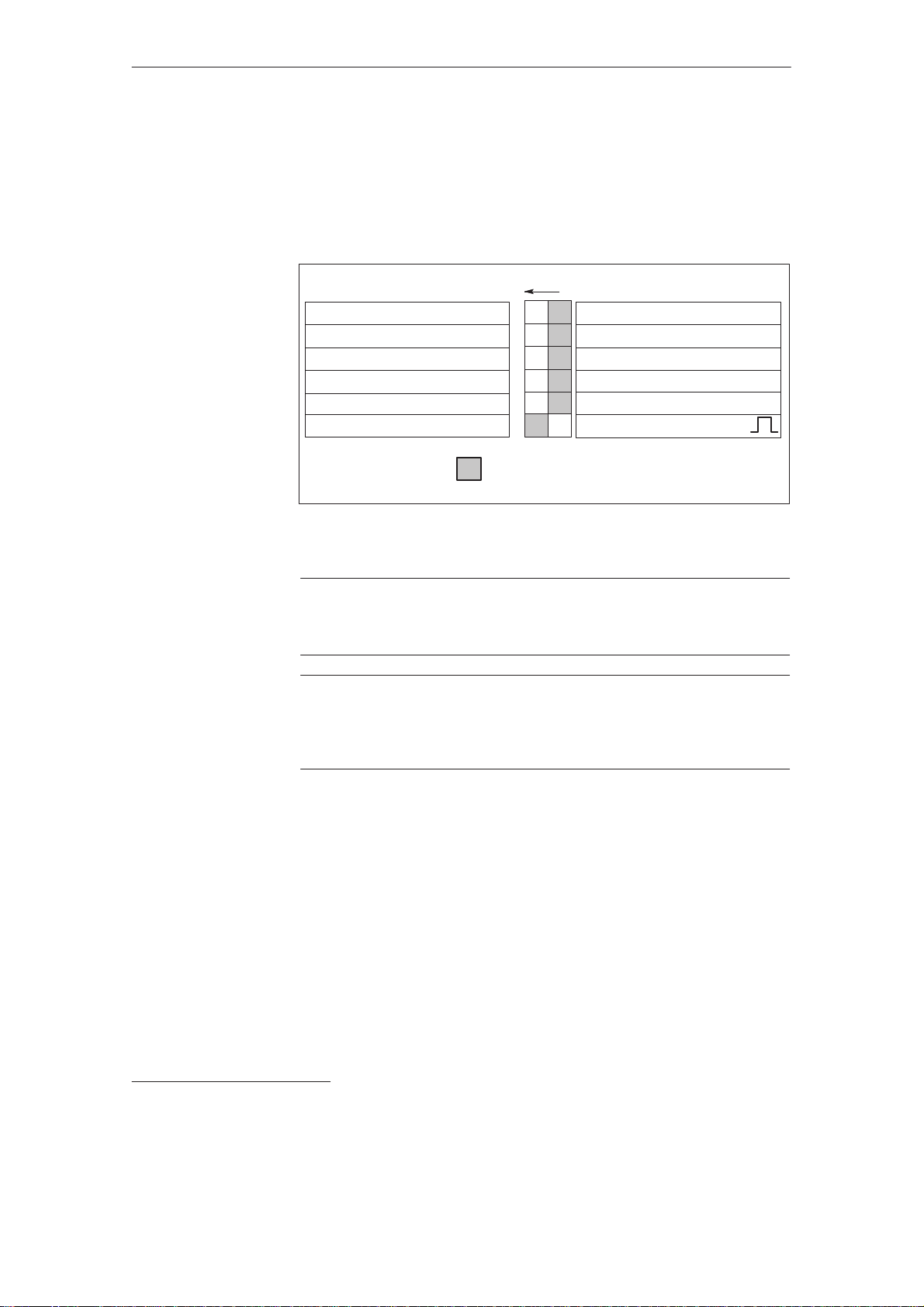
3.1 Function overview and settings
Function overview and settings
A switch S1 is provided on the upper side of the NE and monitoring module to
set the following functions (for UE5 KW on the front panel):
02.98
3
ON: OFF:
U
=415V10% V
supply
Fault message
Regenerative feedback off
=480V+6%–10%
U
supply
Controlled infeed off
Sinusoidal current operation
Standard setting
Figure 3-1DIL switch S1
DC link
=625 V
S1
1)
1
2
3
4
5
6
U
=400V10% V
supply
Ready signal
Regenerative feedback on
Standard, refer to switch S1.1
Controlled infeed
Square–wave current operation
DC link
600 V
1)
Important
!
For I/R modules, Order No. 6SN114–10–01 the basic setting is for
sinusoidal current operation.
Important
!
Terminal 63 (pulse enable) and/or terminal 48 (starting terminal, contactor control) must be de–energized or disconnected before the drive is powered–up or
down using the main circuit–breaker or line contactor!
Switch S 1.1 :
OFF:I/R module, V
UE module V
=400V10%; V
supply
=400V10%; V
supply
Monitoring thresholds: (I/R, UE, monitoring modules)
Pulsed resistor on=644V; Pulsed resistor off=618V
>>=695V
V
ON: I/R module V
DC link
UE module V
=415V10%; V
supply
=415V10%; V
supply
Monitoring thresholds: (I/R, UE, monitoring modules)
Pulsed resistor on=670V; Pulsed resistor off=640V
>>=710V
V
DC link
PW=pulsed resistor
1)
only possible for the I/R module, monitoring thresholds are increased for all NE modules.
Siemens AG 1998 All Rights reserved 6SN1197–0AA00 02.98 Edition
1-20
=600V
DC link
DC link=Vsupply
=625V
DC link
DC link=Vsupply
SIMODRIVE 611 (PJ)
1.35
1.35

02.98
3.1 Function overview and settings
Switch S 1.2 :
OFF:Ready signal (X111 ready relay)
For S1.2=OFF, the relay switches, if the following conditions are fulfilled:
– Internal main contactor CLOSED (terminals NS1 - NS2 connected, ter-
minal 48 enabled)
– Terminal 63, 64=ON (energized)
– No fault present (also not for FD 611 A Standard and resolver and 611 D
drives).
– FD with Standard interface or resolver is enabled in the ”ready” setting
(terminals 663, 65)
– NCU for 840D must have run–up
– MCU must have run–up
ON: Fault message (X111 ready relay)
For S1.2=ON, the relay switches, if the following conditions are fulfilled:
– Internal main contactor CLOSED (terminals NS1 - NS2 connected, termi-
nal 48 enabled)
– No fault present (also not on FD 611 A Standard and resolver or 611 D
drives).
– Feed drive with standard interface or resolver is enabled for the ”Ready”
setting (terminals 663, 65)
– NCU for 840D must have run–up
– MCU must have run–up
Switch S 1.3 :
Switch S 1.4 :
OFF:Standard setting, regenerative feedback active
I/R modules are capable of regenerative feedback.
UE module: The pulsed resistor in the module is effective.
ON: Regenerative feedback disabled
I/R modules: Regenerative feedback is inhibited.
UE module: The pulsed resistor in the
module is not effective.
Comment:
This function is only effective for 10kW from
Order No. 6SN1146–1AC00–0AA1, and for UE 5kW, not for
UE 28kW.
OFF:Standard setting for all NE modules, refer to S 1.1
ON: V
=480V+6% / –10%; V
supply
=700...750V in regenerative feedback operation
V
DC link
DC link=Vsupply
1.35 for infeed operation
Monitoring thresholds: (I/R–, UE–, monitoring modules)
Pulsed resistor on=744V; Pulsed resistor off=718V
>>=795V
V
DC link
S1.4 overwrites the setting of S1.1
Comment: Uncontrolled operation in the infeed direction.
Note
Only in conjunction with modules Order No. 6SN114–10–01.
For motors with shaft height t100: Utilized up to max. 60 k values.
Please observe the Planning Guide, Motors.
S1.4 ON overwrites the functions of S1.5 and S1.1.
Siemens AG 1998 All Rights reserved 6SN1197–0AA00 02.98 Edition
SIMODRIVE 611 (PJ)
1-21

3.1 Function overview and settings
02.98
3
Switch S 1.5 :
Switch S 1.6 :
This function is only available in conjunction with I/R modules
Order No.: 6SN114V–1VV0V–0VV1
OFF:Standard setting, controlled infeed active
ON: Uncontrolled operation in the infeed direction V
DC link=Vsupply
1.35
OFF:Square–wave current operation (the line supply is loaded with a
square–wave current)
ON: This function is only available in conjunction with I/R modules
Order No.: 6SN114V–1VV0V–0VV1
Sinusoidal current operation (the line supply is loaded with sinusoidal
current)
Sinusoidal current is only permissible if the following
components are available:
I/R
16 kW
6SN114V–
1B
V01–0BA1
HF reactor
16 kW
6SN1111–
0AA00–0BA
Line filter for
sinusoidal
current
6SN1111–
0AA01–2BA
1)
16 kW
V
V
I/R
36 kW
6SN114V–
1B
V02–0CA1
HF reactor
36 kW
6SN1111–
0AA00–0CA
Line filter for
sinusoidal
0AA01–2CA
current
36 kW
6SN1111–
1)
V
V
I/R
55 kW
6SN114V–
1B
V0V–0DA1
HF reactor
55 kW
6SN1111–
0AA00–0DA
Line filter for
sinusoidal
1)
filter
55 kW
6SN1111–
0AA01–2DA
V
V
I/R
80 kW
6SN114V–
1BB00–0EA1
HF reactor
80kW
6SN1111–
0AA00–1EA
Line filter for
sinusoidal
0AA01–2EA
current
80 kW
6SN1111–
1)
V
Line filter for
V
6SN114V–
1BB01–0FA1
HF reactor
6SN1111–
0AA00–1FA
sinusoidal
6SN1111–
0AA01–2FA
I/R
120 kW
120kW
current
120 kW
V
1)
V
Important
!
For all of the combinations which are not listed here, only
square–wave current operation setting is permissible.
Table 3-1 Power factor
I/R
I/R
Sinusoidal current operation cos ϕ 0.98 cos λ = 0.97
Square–wave current opera-
cos ϕ 0.98 cos λ = 0.89
tion
UE
cos ϕ 0.87 cos λ = 0.67
cos ϕ: The power factor only includes the basic fundamental
cos λ: Power factor includes the basic fundamental and harmonic components
1)
In the line filters for sinusoidal operation, contrary to the filter modules 6SN1111–0AA01–0VAV for square–wave
current, commutating reactors are not included.
The HF commutating reactor must be mounted externally (refer to p. 1-45).
The line filter is required in order to achieve the CE Conformance for the radio interference voltage.
1-22
Siemens AG 1998 All Rights reserved 6SN1197–0AA00 02.98 Edition
SIMODRIVE 611 (PJ)

04.97
07.94
Service and diagnostics
Display elements of the monitoring– and NE modules
12
34
56
2 Service and dia
Supply infeed (NE)
gnostics
1 LED, red –
2 LED, red – 5 V voltage level faulted
3 LED green – external enable signals not available
4 LED yellow – DC link charged
5 LED, red – line supply fault (single– or multi–phase supply failure at the
6 LED red – DC link overvoltage
Effects:
1 red LED bright:Pulses for the complete drive group are canceled
2 red LED bright: Pulses for the complete drive group are canceled
4 yellow LED dark: xxxx
5 red LED bright: 1) Only the I/R module pulses are canceled (regenerative feedback
6 red LED bright:Pulses for the complete drive group are canceled
1) Line supply fault identification time approx. 30ms
Line supply fault is identified for a three–phase voltage < 280V.
For 1–phase supply failure, the drive axes pulses are canceled after approx. 1 min.
(latched signal) valid for Order No. 6SN1114
15 V electronics power supply faulted
(terminal 63 and/or terminal 64 missing)
terminals U1, V1, W1)
– commutating reactor either not available or incorrectly selected,
– fault level of the line supply or transformer too low
possible causes: Regenerative feedback off, setting–up operation,
line supply fault, for UE pulsed–resistor not operational, line supply
voltage too high, dynamic overload condition
no longer possible. Axes first continue to run. Ready relay drops–out
V–1VV0V–0VV1
1)
Siemens AG 1997 All Rights reserved
SIMODRIVE 611A Installation and Start–Up Guide/IAA/–04.97 Edition
1-23

1-24

02.98
3.2.1 Technical data, supply infeed modules
Technical data
Technical data, supply infeed modules
Table 3-2 Technical data, supply infeed modules, internal cooling
Des.
Monitoringmodule
Monitoring module
Pulsedresistor
Pulsed resistor
UE module, 5/10 kW
UEmodule5/10kW
UEmodule10/25kW
UE module, 10/25 kW
UEmodule28/50kW
UE module, 28/50 kW
I/Rmodule16/21kW
I/R module, 16/21 kW
I/Rmodule36/47kW
I/R module, 36/47 kW
I/Rmodule55/71kW
I/R module, 55/71 kW
I/R module, 55/71 kW pipe
connection
I/R module, 80/104 kW
ipeconnectionorradial
ie connection or radial
p
fan
I/R module, 120/156 kW
ipeconnectionor
ie connection or
p
radial fan
1)
2)
3)
4)
5)
1)
If pipe cooling is not used, only Pv
If the internal pulsed resistor is shutdown, for internal cooling, the only power loss is Pv
The motor braking energy is converted into heat in the integrted pulsed resistor; a heat barrier may be
required, refer to p. 1-34
The 1st number is for cable lugs, the 2nd number is valid for finely–stranded conductors
without connector sleeve.
It can be used: a) 0.3/25 kW b) 2 x 0.3/25 kW c) 1.5/25 kW d) 2 x 1.5/25 kW
Pn/Ps6/P
for supply in-
max
feed [kW]
Pn/Ps6/P
for regenera-
max
tive feedback.
For UE with
internal pulsed resistor
[kW]
Power los-
ses[W]
Pv
/Pv
tot.
int
ext
1)
/Pv-
[kW]
– –
70/–/70 –
–
/310
310/–/10
5/6.5/10
/270
270/–/70
10/13/25
/450
450/–/150
2)
2)
2)
0.3/–/25
(450 V DC)
0.2/–/10
(450 V DC)
0.3/–/25
(450 V DC)
3)
3)
3)
28/36/50
0.3/–/25
5)
(450 V DC)
250/–/250
16/21/35
320/–/320
36/47/70
585/–/585
55/71/91
745/–/745
55/71/91
–/630/115
80/104/131
1280/1090/190
120/156/175
1950/1660/290
16/21/35
16/21/35
36/47/70
36/47/70
55/71/91
55/71/91
55/71/91
55/71/91
80/104/131
80/104/131
120/156/175
120/156/175
has to be taken into account.
tot
Input current
[A]
for 3–ph.
400 V AC,
600 V DC
Pn/Ps6/P
max
Output cur-
rent [A]
–
–
11.3/14.7/22.6
9.3/12/18.6
(540 V DC)
21.8/28.5/54.5
18.5/24/46.5
(540 V DC)
58.5/75/104.5
52/67/93
(540 V DC)
27/35.5/59
26.5/35/58
60.5/79/117.5
60/78/116
92.5/119/153
91/118/151
92.5/119/153
91/118/151
134/175/220
133/173/218
202/262/294
200/260/291
Max.
cross–sec-
4)
tion
[mm2]
16/10
16/10
6/4
6/4
6/4
6/4
16/10
16/10
50
50
16/10
16/10
50
50
95 or
2 x 35
95 or
2 x 35
95 or
2 x 35
150 or
2 x 50
Module
width
[mm]
Weight
[kg]
50 –
5 –
50
5
50
6.5 –
100
9.5 –
200
13.5
100 –
10.5 –
200 –
15.5 –
300 –
26 –
300 –
26 –
300 –
26 –
300 –
28 –
.
int
Energy of
the pulsed
resistor
for 1 x bra-
king ope-
ration
int.: E
max
7.5 kWs
ext.: E
max
180 kWs
int.: E
13.5 kWs
int.: E
7.5 kWs
max
max
=
=
External 1:
=
E
max
7.5 kWs
External 2:
=
E
max
180 kWs
3
=
=
Siemens AG 1998 All Rights reserved 6SN1197–0AA00 02.98 Edition
SIMODRIVE 611 (PJ)
1-25

3.2.1 Technical data, supply infeed modules
Table 3-3 Technical data, supply infeed modules, external cooling
02.98
3
Des.
UEmodule5/10kW
UE module, 5/10 kW
UEmodule10/25kW
UE module, 10/25 kW
I/Rmodule16/21kW
I/R module, 16/21 kW
UEmodule28/50kW
UE module, 28/50 kW
I/Rmodule36/47kW
I/R module, 36/47 kW
I/Rmodule55/71kW
I/R module, 55/71 kW
I/Rmodule80/104kW
I/R module, 80/104 kW
I/Rmodule120/156kW
I/R module, 120/156 kW
Pn/Ps6/P
for supply in-
max
feed [kW]
Losses [W]
Pv
/Pv
ext
int
5/6.5/10
/270
2)
–/–/70
10/13/25
331/119
2)
/
31
16/21/35
270/50
28/36/50
160/90
36/47/70
535/50
55/71/91
630/115
80/104/131
1090/190
120/156/175
1660/290
Pn/Ps6/P
for regenera-
max
tive feedback.
For UE with
internal pulsed resistor
[kW]
[kW]
0.2/–/10
3)
(450 V DC)
3)
03/–/25
0.3/–/25
16/21/35
16/21/35
0.3/–/25
3)
5)
(450 V DC)
36/47/70
36/47/70
55/71/91
55/71/91
80/104/131
80/104/131
120/156/175
120/156/175
Input current
[A]
for 3–ph.
400 V AC,
600 V DC
Pn/Ps6/P
max
Output cur-
rent [A]
11.3/14.7/22.6
9.3/12/18.6
(540 V DC)
21.8/28.5/54.5
18.5/24/46.5
(540 V DC)
27/35.5/59
26.5/35/58
58.5/75/104.5
52/67/93
(540 V DC)
60.5/79/117.5
60/78/116
92.5/119/153
91/118/151
134/174/220
133/173/218
202/262/294
200/260/291
Max.
cross–sec-
4)
tion
[mm2]
6/4
6/4
16/10
16/10
16/10
16/10
50
50
50
50
95 or
2 x 35
95 or
2 x 35
150 or
2 x 50
Module
width
[mm]
Weight
[kg]
50
6.5 –
100
9.5 –
100 –
10.5 –
200
13.5
200 –
15.5 –
300 –
26 –
300 –
26 –
300 –
28 –
Energy of
the pulsed
resistor for
1 x braking
operation
int.: E
13.5 kWs
int.: E
7.5 kWs
max
max
=
=
External 1:
=
E
max
7.5 kWs
External 2:
=
E
max
180 kWs
1)
2)
3)
4)
5)
1-26
If pipe cooling is not used, only Pv
f the internal pulsed resistor is shutdown, for internal coolingthe only power loss is Pv
The braking energy of the motors is converted into heat in the integrated/mounted pulsed resistor,
has to be taken into account.
tot
.
int
if required, a heat barrier may be required, refer to p. 1-34
The 1st number is for cable lugs, the 2nd number is valid for finely–stranded conductors
without connector sleeve.
It can be used: a) 0.3/25 kW b) 2 x 0.3/25 kW c) 1.5/25 kW d) 2 x 1.5/25 kW
Siemens AG 1998 All Rights reserved 6SN1197–0AA00 02.98 Edition
SIMODRIVE 611 (PJ)

02.98
3.2.1 Technical data, supply infeed modules
Definition of
powers
Pn, Ps6, P
modules.
P
n
P
s6
P
max
max
Refer to the following load duty diagrams for the duty cycle diagrams.
Pv
total
Pv
pipe
Pv
ext
Pv
int
Supply
voltage and
frequency
Table 3-4 Supply voltage and frequency
S1, S4 = OFF
Vn = 3–ph. 400V AC
3–ph. 360...440V AC
NE modules up to Pn v55kW
I/R modules Pn = 80/120kW
power connection: U1, V1, W1
Coil connection: L1, L2
3–ph. 300...360V AC
3–ph. 360...440V AC
3–ph. 300...360V AC
Data is valid for the total, permitted voltage range of the I/R
Continuous output of the NE module.
Output for max. 4 min for an S6 duty cycle.
Peak output.
Total module power loss;
Power loss dissipated with pipe cooling;
Power loss dissipated with external cooling;
Power loss which cannot be dissipated through pipe– or ex-
ternal cooling.
This power loss remains in the cabinet.
45...65Hz
45...65Hz
S1 = ON
Vn = 3–ph. 415V AC
3–ph. 373...457V AC
1)
3–ph. 312...373V AC
45...65Hz
3–ph. 373...457V AC
1)
3–ph. 312...373V AC
45...65Hz
3–ph. 360...457V AC / 45...53Hz
3–ph. 400...510V AC / 57...65Hz
1)
1)
S4 = ON
Vn = 3–ph. 480V AC
3–ph. 432...509V AC
3–ph. 408...432V AC
55...65Hz
3–ph. 432...509V AC
3–ph. 408...432V AC
55...65Hz
1)
1)
Cooling type
All I/R modules and the UE 28 kW are force ventilated.
The UE modules 5kW, 10kW, the monitoring module as well as the pulsed resi-
stor module, are self–ventilated.
No ground–fault
Before powering–up for the first time, the cabinet wiring, motor/encoder feeder
cables and the DC link connections must be checked to ensure that they do not
have a ground fault.
1)
The drive power supply can be operated in the range from 3–ph. 323 to 3–ph. 509 V AC. However, for I/R modules,
operation of the power supply up to 3–ph. 280 V AC is only valid as long as the I/R module actively controls the
DC link voltage 600 V or 625 V and there is a three–conductor connection (as set in the factory).
De–rating to 0.7P
A
2)
In the infeed direction, the DC link voltage is uncontrolled, therefore a 600 V DC link voltage
will not be achieved. Observe the restrictions regarding the acceleration time and stall torque of the motors.
Siemens AG 1998 All Rights reserved 6SN1197–0AA00 02.98 Edition
SIMODRIVE 611 (PJ)
P
+E
P
. Power supply rating must, under the conditions, also be reduced to 70%.
n
0.7 x (17+8) or for UE 5 kW 0.7 x (7+3.5)
1-27
3.2.1 Technical data, supply infeed modules
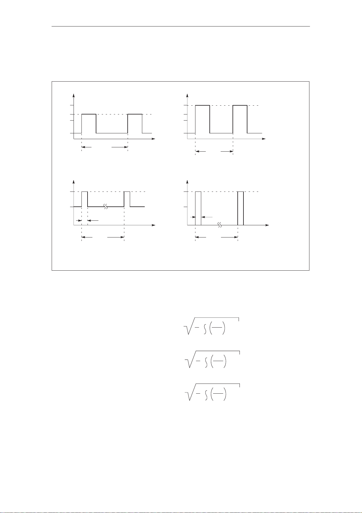
Rated load duty
cycles for NE modules
02.98
3
P
max
P
s6
P
n
0.4 P
P
max
P
n
P
n
P
condition
4 min
0.2 s
10 min
10 s
P
P
max
P
s6
P
n
0.4 P
t
10 s
n
t
60 s
Peak output duty cycle with pre–loading conditionS6 duty cycle with pre–loading condition
P
FP
n
P
n
4 s
t
t
10 s
Peak output duty cycle without pre–loading conditionPeak output duty cycle with pre–loading
F:For all NE modules up to Pn 80 kW, F=1.6
For Pn=120 kW, F=1.4
Figure 3-2
The following rule of thumb is valid:
For load duty cycles with a period T10 s:
For load duty cycles with a period 10 s < T 1 min:
T
1
T
0
T
1
T
0
T
1
T
0
P
2
P
(t)
dt < 1.03;
P
n
2
P
(t)
dt < 0.90;
P
n
2
P
(t)
dt < 0.89;For load duty cycles with a period 1 min < T 10 min:
P
n
= the instantaneous power demand
(t)
Pn < P
(t)
tŮ[0, T ]
Pn < P
(t)
tŮ[0, T ]
< P
P
n
(t)
tŮ[0, T ]
P
P
P
max
max
max
;
;
;
1-28
Siemens AG 1998 All Rights reserved 6SN1197–0AA00 02.98 Edition
SIMODRIVE 611 (PJ)
02.98
3.2.1 Technical data, supply infeed modules
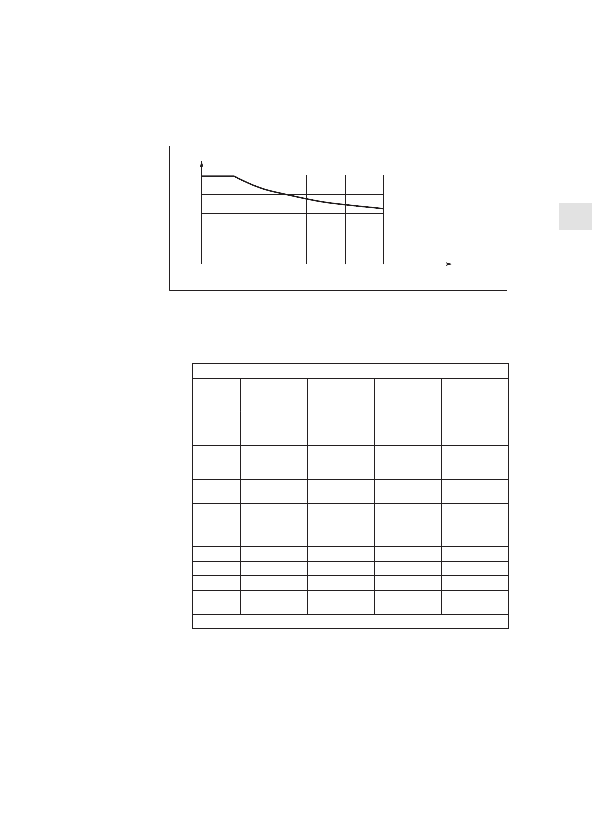
De–rating as a
function of the installation altitude
All of the specified outputs are valid up to an installation altitude of 1000 m. For
an installation altitude > 1000 m, the specified outputs should be reduced according to the diagrams below. For installation altitudes > 2000 m
1)
transformer must be used (refer to Section 2.4).
X
H
100 %
80 %
60 %
40 %
20 %
0 %
0
1000
Figure 3-3
Caution: Pn, Ps6 and P
Table 3-5 UE modules with pulsed resistors
Order No.,
pulsed resistor
Integrated
in
Can be
used for
Can be
used for
Pn 0.3 kW 1.5 kW 0.3 kW 0.2 kW
P
max
E
max
Degree of
protection
Dimension drawings, refer to p. 1-161
2000
External pulsed
resistor 0.3/25
kW
6SN1113–
1AA00–0DA0
UE module 28kWUE module 28
25 kW 25 kW 25 kW 10 kW
7.5 kWs 180 kWs 7.5 kWs 13.5 kWs
IP 54 IP20 refer to module refer to module
3000 4000 5000
must be de–rated in the same way.
max
Pulsed resistors, technical data
External pulsed
resistor 1.5/25
kW
6SN1113–
1AA00–0CA0
– – UE 10 kW,
kW
–
Pulsed resistor
module
6SN1113–
1AB0–0BA
P
n altitude=xHPn1000m
P
n altitude=xHPs61000m
P
max. altitude=xHPmax.
/100%
1000m
Installation altitude (m)
Internal pulsed
resistor 0.3/25
kW
– –
pulsed resistor
module
– –
– –
Internal pulsed
resistor 0.2/10
kW
UE 5 kW
an isolating
/100%
/100%
1)
The rated insulation voltage depends on the installation altitude.
Siemens AG 1998 All Rights reserved 6SN1197–0AA00 02.98 Edition
SIMODRIVE 611 (PJ)
1-29
3.2.1 Technical data, supply infeed modules
02.98
3
Engineering information is valid for
UE 5 kW, 10 kW,
28 kW and pulsed
resistor module
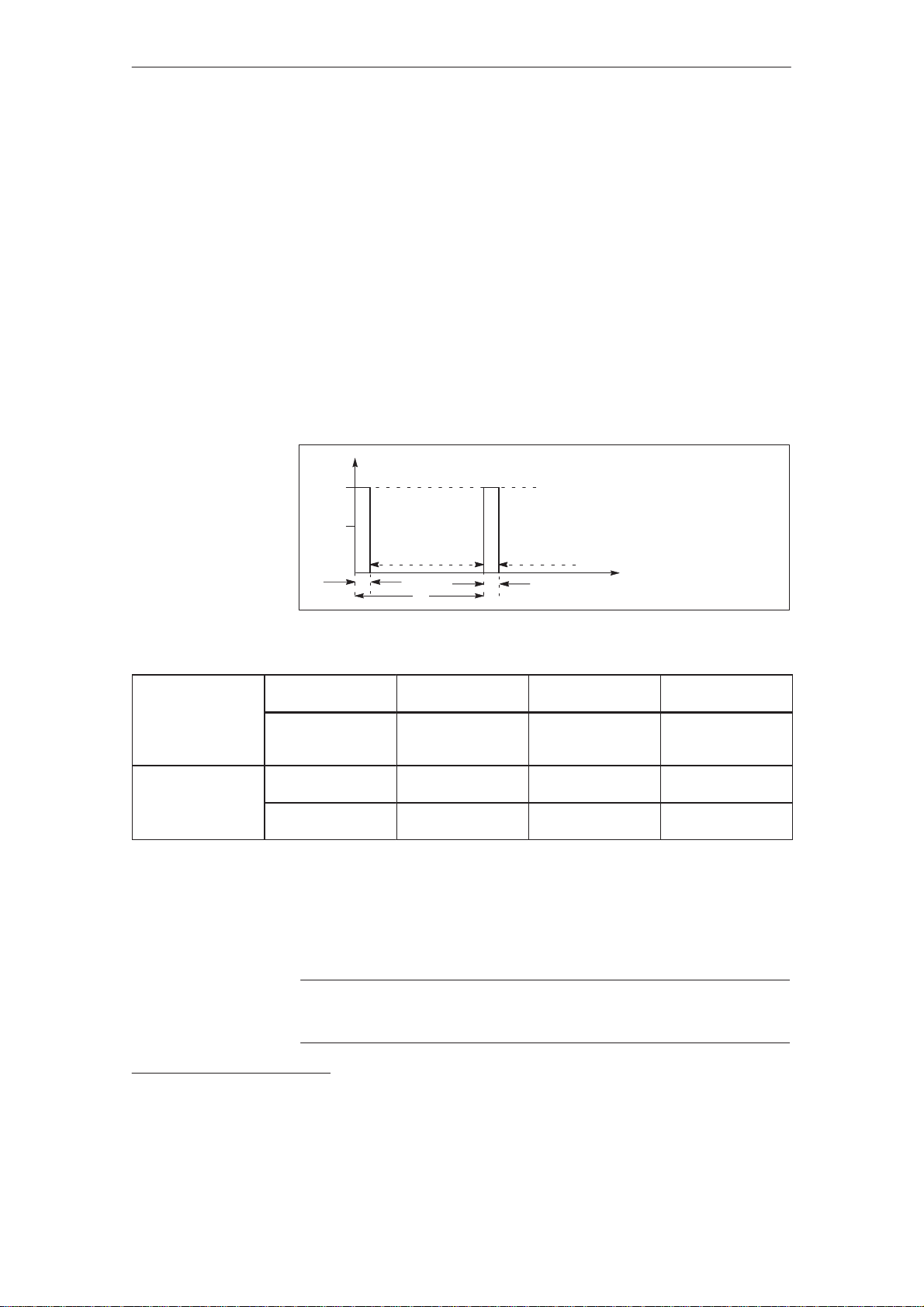
Load duty cycles
for braking operations
Dimensioning the load duty cycles with pulsed resistors
Des.Units Explanation
E Ws Regenerative feedback energy when braking a motor from n
to n
1
T s Period of the braking load duty cycle
A s Load duration
2
J kgm
Total moment of inertia (including J motor)
M Nm Braking torque
n RPM Speed
Pn W Continuous rating of the pulsed resistor
W Peak rating of the pulsed resistor
P
max
Ws Energy of the pulsed resistor for a single braking operation
E
max
P (kW)
P
max
P
n
0 kW 0 kW
A
T
A
t (s)
2
Table 3-6 Examples
Example A=
Figure 3-4Load duty cycle for internal and external pulsed resistors
E
Pn
P
T=
A=
T=
max
max
Pulsed resistor
0.2/10 kW
13500 Ws
10000 W
1)
200 W
0.2 s
10 s
1.35 s
67.5 s
Pulsed resistor
0.3/25 kW
7500 Ws
300 W
25000W
0.12 s
10 s
0.3 s
25 s
Pulsed resistor
1.5/25 kW
180000Ws
All of the following conditions must be fulfilled:
1.P
2.Emax E; E=J[(2πn
3.P
M2πn/60
max
E/T
n
/60)2–(2πn1/60)2]/2
2
Note
For UE 5 kW and UE 10 kW, it is not possible to connect an external resistor.
1500 W
25000W
0.6 s
10 s
7.2 s
120 s
1)
As a result of the mechanical dimensions, the resistor can accept a relatively high level of energy.
Siemens AG 1998 All Rights reserved 6SN1197–0AA00 02.98 Edition
1-30
SIMODRIVE 611 (PJ)
 Loading...