

Siemens SIMATRIX NEO V2 Configuration Manual
SIMATRIX NEO V2
Configuration Manual
Siemens AB
Security Products

Liefermöglichkeiten und technische Änderungen vorbehalten.
Data and design subject to change without notice. / Supply subject to availability.
© 2013 Copyright by
Siemens Building Technologies
Wir behalten uns alle Rechte an diesem Dokument und an dem in ihm dargestellten Gegenstand vor. Der Empfänger erkennt diese Rechte
an und wird dieses Dokument nicht ohne unsere vorgängige schriftliche Ermächtigung ganz oder teilweise Dritten zugänglich machen oder
außerhalb des Zweckes verwenden, zu dem es ihm übergeben worden ist.
We reserve all rights in this document and in the subject thereof. By acceptance of the document the recipient acknowledges these rights
and undertakes neither to publish the document nor the subject thereof in full or in part, nor to make them available to any third party without
our prior express written authorization, nor to use it for any purpose other than for which it was delivered to him.
Contacting us
If you have questions or suggestions regarding the product or this documentation,
please contact our Technical Competence Center.
E-mail: mailto:sp.support.de@siemens.com
Tel.: +49 721 95 88088 (English)
Internet: www.siemens.com/securityproducts
Trainings
Siemens provides training courses for all products.

3
Siemens AB
Security Products
Contents
1 Safety .......................................................................................................5
1.1 Target readers...........................................................................................5
1.2 Work safety information ............................................................................5
1.2.1 General information...................................................................................5
1.2.2 Transport...................................................................................................5
1.2.3 Setup.........................................................................................................6
1.2.4 Mounting ...................................................................................................6
1.2.5 Installation ................................................................................................. 6
1.2.6 Service and maintenance .........................................................................7
1.3 Meaning of the written warning notices ....................................................8
1.4 Meanings of the hazard symbols ..............................................................8
2 Directives and standards.......................................................................9
3 Technical data.......................................................................................10
3.1.1 Video .......................................................................................................10
3.1.2 Control.....................................................................................................10
4 Ordering information............................................................................12
5 Total system with full options .............................................................13
5.1 Performance characteristics ...................................................................14
5.2 Functional description .............................................................................16
5.3 Settings on the CD-ROM ........................................................................17
5.3.1 Basic program.........................................................................................17
5.3.2 Alarm program 2 (factory setting) ...........................................................18
5.4 Interfaces ................................................................................................19
5.5 Peripheral device address allocation ......................................................20
5.6 Front display............................................................................................20
5.6.1 Status displays ........................................................................................ 20
5.6.2 Key allocation..........................................................................................21
5.6.3 Indicator lamps........................................................................................21
6 Installation.............................................................................................22
6.1 SIMATRIX NEO V2 connections.............................................................23
6.1.1 Interfaces and connections .....................................................................23
6.1.2 Pin allocation for the 4-pin RJ9 telemetry port sockets...........................24
6.1.3 Pin allocation for the 6-pin RJ12 keyboard sockets................................25
6.1.4 Pin allocation for the COM2/3 and COM4 9-pin connectors...................25
6.1.5 Pin allocation for the 37-pin Sub-D alarm 1 - 16 and alarm 17 – 32
sockets ....................................................................................................27
6.1.5.1 Connecting camera head drives (CDCs) ................................................28
6.1.5.2 Connecting the TTY/TTL interface converter (CAC0101) ......................29
6.1.5.3 Connecting the converter for dome cameras (CAC0103) ......................30
6.1.5.4 Connecting alarm sensors ......................................................................31
6.1.6 SysLink socket allocation........................................................................31
6.1.7 Pin allocation for the 25-pin Sub-D "Alarm out" socket...........................32
6.2 Connecting the video inputs....................................................................33
6.3 Connecting the video outputs .................................................................33
6.4 Mains connection ....................................................................................33
7 Set-up.....................................................................................................34
7.1 Hardware.................................................................................................34
7.2 Installing the control software and setting device parameters................35
7.3 Programming the SIMATRIX NEO..........................................................36
8 System extensions ...............................................................................37

4
Siemens AB
Security Products
8.1 Basic unit.................................................................................................37
8.1.1 Extension to a maximum of 128 video inputs .........................................37
8.1.2 Extension up to a maximum of 32 video outputs (SIMNEO-OM) ...........38
8.2 Extension bay..........................................................................................39
8.2.1 Connecting up the cables (up to 16 video outputs) ................................39
8.2.2 Connecting up the cables (more than 16 video outputs) ........................40
8.2.3 Extension to a maximum of 240 video inputs .........................................40
8.2.4 Extension up to a maximum of 32 video outputs (SIMNEO-SOM).........41
8.3 Alarm box ................................................................................................42
9 Maintenance...........................................................................................44
10 Disposal .................................................................................................45
11 Appendix................................................................................................46
11.1 Glossary ..................................................................................................46
11.2 Summary of basic and alarm program features......................................47

Safety
1 Safety
1.1 Target readers
The instructions in this document are designed for the following target readers:
Operational startup personnel
Qualification Activity Condition of the
equipment
Technical training for
building or electrical
installations.
Puts the product into
operation for the first time.
The product is not yet
installed and configured.
1.2 Work safety information
1.2.1 General information
Read the general safety precautions before operating the device.
Follow all warnings and instructions marked on the device.
Keep this document for reference.
Always pass this document on together with the product.
Any national or local safety standards or laws that apply to the development,
design, installation, operation or disposal of a product must be adhered to in
addition to the instructions in the product documentation.
In case of product failure please contact our Service hotline.
Liability claim
Do not connect the device if it is damaged or any parts are missing.
Do not make any changes or modifications to the device unless they are
expressly mentioned in this manual and have been approved by the
manufacturer. Unauthorized changes will void the user's authority to operate the
equipment.
Use only spare parts and accessories approved by the manufacturer.
Radio interference with other devices in the environment
This is a Class B device. This equipment may cause radio interference in a
residential installation. In this case the user is encouraged to perform
appropriate measures to correct the interference.
1.2.2 Transport
Damage during transport
Keep the packaging material for future transportation.
Do not expose the device to mechanical vibrations or shocks.
5
Siemens AB
Security Products

Safety
1.2.3 Setup
Damage due to unsuitable mounting location
Observe the environmental requirements recommended by the manufacturer.
See Section 3: „Technical data“.
Do not operate the device close to sources of powerful electromagnetic
radiation.
Protect the device against moisture.
Do not operate the device in excessively dusty places.
Make sure that no objects, especially metal objects, can enter the device.
Do not expose the device to mechanical vibrations or shocks.
Liability claim
For reasons of electromagnetic compatibility RS232, USB, audio in/out and
power supply cables must not exceed 3 meters length.
Damage to the device due to overvoltage
Connect the device only to power sources with the specified voltage. Voltage
supply requirements can be found on the power supply unit/type label.
1.2.4 Mounting
Cable damage due to mechanical load
When connecting the cables, do not apply tensile force and make sure not to
bend or damage them.
1.2.5 Installation
If the Video matrix shows external damage, do not connec t the device!
Connect the device only to an appropriate power source.
The device is designated to be operated with earthed three-phased supply, so
called TN-network (according to VDE 0100, section 300 or EN60950). For safe
operation the device must be connected through an installation fuse of max. 16
A.
Connection to IT networks, without earthed conductors (insulated) or only
through impedance earthed conductors, is not permitted.
The device can be connected to power supplies with 115 or 230 Volts (+10%/-
15%), 50/60Hz. For connecting to the power supply, an external isolator is
necessary.
During operation of the device, some components are inevitably under HT (very
high voltage). Even after fuse failure dangerous voltages can still be present in
the device.
Use the device only in conjunction with a power supply cable that has been
approved in your country and complies with the national standards.
Important information for Norway and Sweden:
6
Siemens AB
Security Products

Safety
7
Security Products
CAUTION
Devices that are connected to the protective earth system of a building and to a
coax cable distribution system either directly or via other devices may, under
certain circumstances, cause a fire hazard. Connection to a cable distribution
system therefore is to be provided through a device providing electrical isolation
below a certain frequency range (galvanic isolator, see EN 60728-11).
1.2.6 Service and maintenance
Risk of electric shock during maintenance
Always disconnect the power cable and other cables from the device before
performing maintenance.
Danger of electrical shock while cleaning the device
Disconnect the device from the mains supply before cleaning it.
Do not use liquid cleaners or sprays that contain alcohol, spirit or ammonia.
Siemens AB
Safety
1.3 Meaning of the written warning notices
Signal word Type of risk
DANGER Risk of death or severe bodily injury
Warning Possible danger of death or severe bodily harm
CAUTION There is a risk of minor injuries or damage to property
IMPORTANT Malfunctioning may result
1.4 Meanings of the hazard symbols
Warning Caution - Dangerous area!
Warning Caution - Dangerous electrical voltage!
8
Siemens AB
Security Products

Directives and standards
2 Directives and standards
This product complies with the requirements of the European Directives
2004/108/EEC “Directive of Electromagnetic Compatibility” and 2006/95/EEC “Low
Voltage Directive”. The EU declaration of conformity is available to the responsible
agencies at:
Siemens AB
Infrastructures & Cities Sector
Security Products
International Headquarters
Englundavägen 7
SE-171 41 SOLNA
European Directive 2004/108/EEC "Electromagnetic Compatibility"
Compliance with the European Directive 2004/108/EEC has been proven by
testing according to the following standards:
Electromagnetic emission EN 55022 Class B
Electromagnetic
compatibility
EN 50130-4
European Directive 2006/95/EEC „Low-Voltage Directive”
Compliance with the European Directive 2006/95/EEC has been proven by testing
according to the following standards:
Safety: EN 60950-1
9
Siemens AB
Security Products

Technical data
3 Technical data
3.1.1 Video
Video inputs BNC sockets
U
ss
=1V video, 75 , with plug-in jumpers and switchable
terminations
Video outputs BNC sockets
U
ss
=1V video, 75
Video signal failure recognition Vertical synchronisation pulse monitoring
Text overlay Complete IBM character set,
internal synchronisation,
character display: white background, black frame
Field size: 12 text lines of 24 characters each
Character height: 18 screen lines
Cross-talk attenuation 56 dB at 5 MHz
Differential amplification 1%
Differential phase 0,6
Frequency response characteristic -0.5 dB at 6 MHz
Switching point change-over time after
command signal reception at the video matrix
80 ms (typical), 200 ms (max.)
3.1.2 Control
Control computer 6 RISC-Controller
Interfaces for
Progr.-PC, IVM-NT, TELEMAT, SIPASS, LMS 3 x V.24 interfaces
Baud rate: 1200 – 19,200 bit/s
Connection: 3 x 9-pin Sub-D connectors
Keyboards 8 x TTY(20mA) interfaces with built-in electrical supply for 8
keyboards, (supply max. 800mA total)
Cable length: up to 2 km, wire diameter 0.8 mm
Baud rate: 1200 – 9600 bit/s
Connection: 8 x RJ12 sockets
PTZ control (CDC) 16 x CDC(20mA) interfaces
Cable length: up to 2 km, wire diameter 0.8 mm
Baud rate: 1200 – 9600 bit/s
Control of Telemetrie devices 4 x RS422/RS485-Ports;
Protocols: CCDA, SCU, SIVIS, PELCO-D
Connection: 4 x RJ11-Buchse / Port
Sensor groups
Alarm sensors, alarm contacts
32 x alarm inputs for detection groups
Cable length: up to 10 m
Connection: 2 x 37-pin Sub-D socket
10
Siemens AB
Security Products

Technical data
Video recorder, Picture storage 8 control outputs (open-collector); max. 30 V, max. 50 mA
Relay with 2 voltage-free change-over contacts for collective alarm
signalling; max. 48 V, 250 mA;
Connection: 1 x 25-pin Sub-D socket
LAN / Ethernet 8P8C modular plug (RJ45) with 10/100 Base-T Ethernet port for
configuration via network, connection of LAN components, status
request via integrated Web server
Power supply 115 – 230 V AC, tolerance: +10%/-15%
Switching power supply, 50 to 60 Hz
The mains socket is fitted with two microfuses (1.6 A slow-blow)
Power requirement Maximum system size: 55 VA
per 16 input coupler PCB: 1.4 VA
per 8 output coupler PCB: 2.8 VA
Operating temperature 5 to 45 C
Relative humidity 30 to 85 %, non-condensing
Construction 19 inch chassis, 6 HU
Dimensions (w x h x d, chassis without 19”-
mount)
441 x 266 x 217 mm
11
Siemens AB
Security Products

Ordering information
4 Ordering information
Order reference Short
designation
Product Weight
(approx.
In kg)
2GF2211-8AA SIMNEO-168 SIMATRIX NEO V2 168, complete, 19" base module, 6 HU, PAL model*, incl. CPU,
16 video inputs, 8 video outputs, 32 alarm inputs
*Note: NTSC model available on request
6.5
Extension options
2GF2211-8AB SIMNEO-EXT SIMATRIX NEO V2 19" extension bay, 6 HU,
incl. 32 video inputs, 16 video outputs
6.3
2GF2211-8CA SIMNEO-IM Video input module, 16 extra video inputs 0.24
2GF2211-8DA SIMNEO-OM Video output module with text overlay,
upgrade for the base module with 8 extra video outputs
0.03
2GF2211-8DB SIMNEO-SOM Video output module without text overlay,
8 extra video output upgrade for the extension bay
0.03
2GF2211-8EA SIMNEO-A128 Alarm box, 128 alarm inputs, 19" module, 1 HU 2.50
Accessories
2GF2400-8EA CKA 3210 Keyboard without joystick 0.9
2GF2400-8EB CKA 4810 Keyboard with joystick 1.05
2GF2400-8DA SUT 48 Keyboard with keys (customer-specified lettering) and joystick 1.2
2GF1800-8BE PSU230-12 Plug-in power supply unit
for the external power supply of the keyboards,
230 V, 50 Hz/12 V DC, 640 mA,
for interior use, complete with 2 m DC cable with open, tinned ends
0.53
2GF2207-8AE
2GF2207-8AF
2GF2207-8AG
SIM-CC3
SIM-CC7
SIM-CC10
- 3 m connection cable for keyboard
- 7 m connection cable for keyboard
-10 m connection cable for keyboard
2GF2208-8AG SIM-PC Connection cable for external computers with 9-pin AT connector, 2 m long, for
programming the video matrix and loading the alarm program.
2GF5505-8BA CAC0101 TTY/TTL interface converter 0.1
S24245-F5046-A1 CAC0103 DOME converter 0.6
2GF5505-8AK TTY1X8 TTY distributor, 8 port 0.2
S24245-B5015-A1 CDC0501 PTZ drive control unit for pan/tilt camera heads without presets 2.85
S24245-B5017-A1 CDC0502 PTZ drive control unit for pan/tilt camera heads with position memory for 64 presets 2.85
2GF1708-8EA CDD2410 PTZ drive 7.0
12
Siemens AB
Security Products
Total system with full options
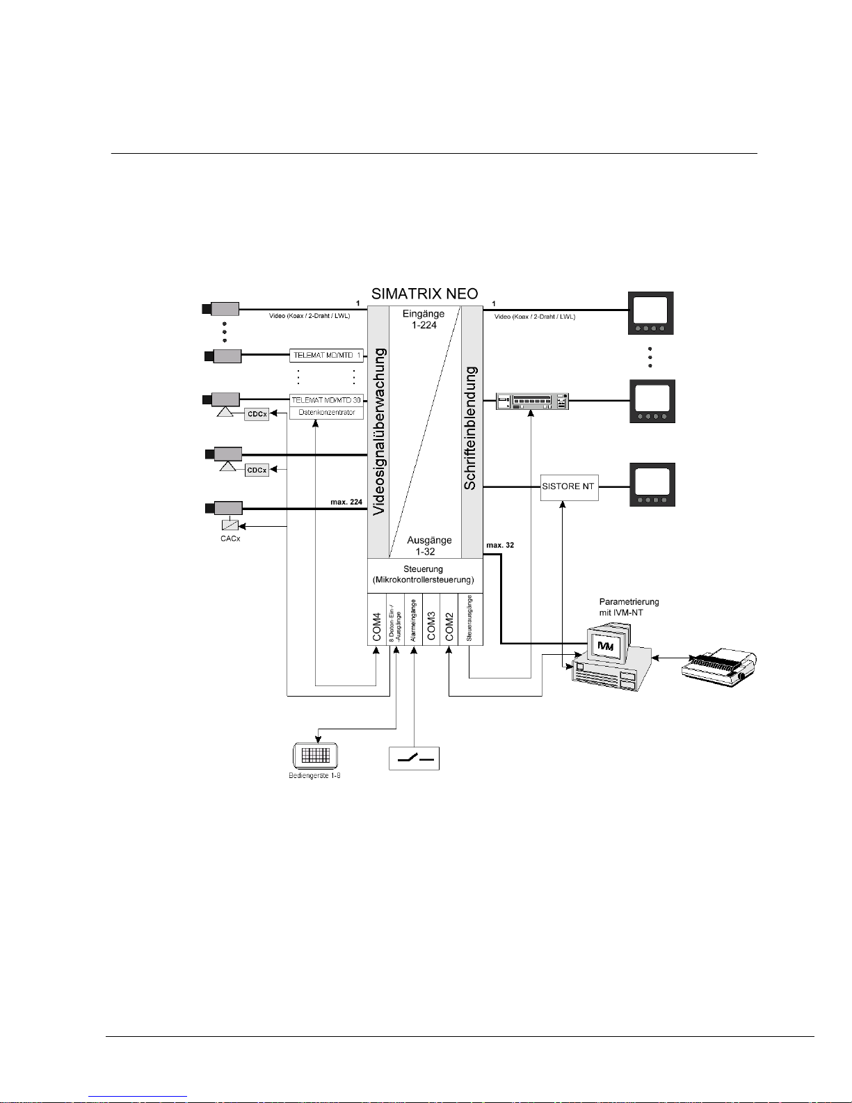
5 Total system with full options
The SIMATRIX NEO V2 video matrix allows CCTV systems to be constructed in a
compact, modular format.
SIMATRIX NEO not only allows the connection of video signals using keyboards, it
also allows contact-controlled alarm processing and makes it possible to interface
to higher-level management systems such as IVM, the hazard alert system
TOPSIS, etc.
Fig. 1 System configurations with TELEMAT MD/MTD, IVM, SISTORE and
detection groups (alarms)
13
Siemens AB
Security Products

Total system with full options
5.1 Performance characteristics
The SIMATRIX NEO V2 video matrix consists of a six standard height unit module
(6HE), which contains both the system controls and the switching matrix.
A maximum of 128 video input signals can be switched at will to a maximum of
32 video outputs (224 video input signals if the extension bay is used).
Video
– SIMATRIX NEO, modular 19 inch system
– Base model: 16 inputs to 8 outputs
Full spec. capacity: 224 inputs to 32 outputs (using the extension bay) or
Full spec. capacity: 240 inputs to 16 outputs (using the extension bay)
– Number of inputs extendible in steps of 16
Number of outputs extendible in steps of 8
6 standard height unit Matrix Component Tray (MCT), extendible to up to a
maximum of 128 inputs and 32 outputs
– Video signal input via BNC sockets
75 Ohm terminating resistor can be switched off via a jumper.
– Video signal failure monitor
Like the SIMATRIX SYS, the SIMATRIX NEO V2 features its own built-in video
monitoring axis. This means that all the outputs remain available, even when
signal monitoring is active.
Control
– One 8P8C modular socket (RJ45) for connection to a 10/100 Base-T network,
for connection of LAN components, status request via integrated Web server, as
well as parameter setting, integration of central sub-units.
– Three serial interfaces (RS232) for the connection of external systems, such as
IVM-NT, TELEMAT MD/MTD, SISTORE NT, LMS, programming via a PC and
secondary control system dialling
– Connection of up to 8 keyboards with freely programmable keys
– 16 serial CL / TTY interfaces for the connection of telemetry devices (CDCs) for
cameras with pan/tilt and lens controls
– Connection options for telemetry devices via RS485 interfaces with protocols for
CCDA, SCU, Sivis Minidome, Pelco D, PST95 and Molynx-C.
– 32 alarm inputs in the basic unit, expansion possibility to 255 alarm inputs using
extension / alarm boxes.
– The software supports a maximum of 8 keyboards with freely programmable
keys
– CD-ROM with basic program and 6 alarm programs complete with settings, for
Windows 98/ME/2000/XP
– Preset positions for camera head controls and dome cameras, which can be
called up individually or in sequence
– Remote programming of digital cameras via CAC0101 (dome converter)
– 8 universal open-collector control outputs for controlling external devices
– Relay with 2 voltage-free change-over contacts
14
Siemens AB
Security Products

Total system with full options
– Connection option for a log printer
Options
– Alarm box with 128 alarm inputs
– Extension bay for upgrading to a total of 224 video inputs
– 16-input extra video input extension module
– 8-output extra video output extension module
Operation
– Simple graphical control and visualisation interface using Integrated Video
Management (IVM-NT)
– Control via freely programmable keyboards
Programming
The following functions of the SIMATRIX NEO V2 are programmable:
– Time and weekday controlled alarm programs
– Alarm group switching (max. 4 cameras)
– Alarm and home positions of cameras with pan/tilt and lens controls
– Alarm image sequence on one monitor for gap-free recording of alarm images
– Log functionality via serial interface.
– Password-protected activation or deactivation of detection groups
– On-screen text and time insertion for the keyboards
– Real-time clock (date + time), display on up to 8 monitors
– Camera labels (IBM character set, 12 lines of 24 characters each) per camera
– Group switching (max. 8 cameras)
– Operating stations with switching allocation
– Automatic camera image sequence per video output, can be programmed to
start up when the system is switched on
– 32 freely programmable predefined sequences with 32 video inputs per
sequence, which can be freely allocated to the video outputs
– Keyboards with freely programmable keys
– Screen menus in German, English and Spanish
– Parameter set can be stored as a data file (library function)
– Macro capability: The macros can be triggered through keyboard operation, by
an alarm contact, or during the booting process (1 start macro)
15
Siemens AB
Security Products
 Loading...