

Page 1

SIMATIC
VS 710
Quick Reference Guide
A5E00032597-02
Edition 11/2001
Page 2

The reproduction, transmission or use of this document or its
contents is not permitted without express written authority. Offenders
will be liable for damages. All rights, including rights created by patent
grant or registration of a utility model or design, are reserved.
We have checked the contents of this manual for agreement with the
hardware and software described. Since deviations cannot be entirely ruled out, we cannot guarantee full agreement. However, the
data in this Quick Reference Guide are reviewed regularly and any
necessary corrections included in subseqeuent editions. Suggestions for improvement are welcome.
Technical data subject to change.
Disclaimer of Liability
Copyright W Siemens AG 1999-2001 All Rights Reserved
Siemens Aktiengesellschaft
A5E00032597
Printed in the Fed. Rep. of Germany
Page 3

SIMATIC VS710Contents
SIMATIC VS 710
A5E00032597-02
iii
Contents
1 Product Overview 1 . . . . . . . . . . . . . . . . . . . . . . . .
1.1 Applications 2 . . . . . . . . . . . . . . . . . . . . . . . . . . . . . . . . . . . . . . . . .
1.2 Contents of the Consignment 2 . . . . . . . . . . . . . . . . . . . . . . . . . . . .
VS 710 Package 2 . . . . . . . . . . . . . . . . . . . . . . . . . . . . . . . . . . . . . .
VS 710 OEM Package: 2 . . . . . . . . . . . . . . . . . . . . . . . . . . . . . . . .
1.3 Accessories 3 . . . . . . . . . . . . . . . . . . . . . . . . . . . . . . . . . . . . . . . . .
2 VS 710 Hardware 4 . . . . . . . . . . . . . . . . . . . . . . . . .
2.1 Hardware Components 4 . . . . . . . . . . . . . . . . . . . . . . . . . . . . . . . .
2.2 Mounting the VS 710 5 . . . . . . . . . . . . . . . . . . . . . . . . . . . . . . . . . .
Dimensions, Mounting Fixtures 6 . . . . . . . . . . . . . . . . . . . . . . . . . .
Mounting Bracket 8 . . . . . . . . . . . . . . . . . . . . . . . . . . . . . . . . . . . .
Lens Socket 8 . . . . . . . . . . . . . . . . . . . . . . . . . . . . . . . . . . . . . . . . .
2.3 Hardware Interfaces 9 . . . . . . . . . . . . . . . . . . . . . . . . . . . . . . . . . . .
2.4 Power Supply - Connector Pinout 10 . . . . . . . . . . . . . . . . . . . . . . . .
24 VDC Power Supply 11 . . . . . . . . . . . . . . . . . . . . . . . . . . . . . . . .
2.5 Digital Input / Output - Connector Pinout 12 . . . . . . . . . . . . . . . . . .
Wiring Diagram (Digital Input Points) 13 . . . . . . . . . . . . . . . . . . . . .
Wiring Diagram (Digital Output Points) 14 . . . . . . . . . . . . . . . . . . .
2.6 DP Connector Pinout 15 . . . . . . . . . . . . . . . . . . . . . . . . . . . . . . . . . .
2.7 VGA Connector Pinout 16 . . . . . . . . . . . . . . . . . . . . . . . . . . . . . . . .
2.8 RS232 Connector Pinout 17 . . . . . . . . . . . . . . . . . . . . . . . . . . . . . . .
2.9 IDE Flashdisk 18 . . . . . . . . . . . . . . . . . . . . . . . . . . . . . . . . . . . . . . .
3 Connecting the VS 710 19 . . . . . . . . . . . . . . . . . . . . .
3.1 Safety Recommendations 19 . . . . . . . . . . . . . . . . . . . . . . . . . . . . . .
3.2 System Environment 20 . . . . . . . . . . . . . . . . . . . . . . . . . . . . . . . . . .
3.3 Connection Options 21 . . . . . . . . . . . . . . . . . . . . . . . . . . . . . . . . . . .
Function in Configure Mode 21 . . . . . . . . . . . . . . . . . . . . . . . . . . . .
Function in Productive Mode 21 . . . . . . . . . . . . . . . . . . . . . . . . . . . .
Page 4

SIMATIC VS710 Contents
iv
SIMATIC VS 710
A5E00032597-02
4 Interactive Operation 22 . . . . . . . . . . . . . . . . . . . . .
4.1 Keyboard and Floppy Emulation 22 . . . . . . . . . . . . . . . . . . . . . . . . .
4.2 HOSTKEY Program 22 . . . . . . . . . . . . . . . . . . . . . . . . . . . . . . . . . .
Setup Options 23 . . . . . . . . . . . . . . . . . . . . . . . . . . . . . . . . . . . . . . .
Operator Input to HOSTKEY 23 . . . . . . . . . . . . . . . . . . . . . . . . . . .
4.3 Operating DOS 6.22 and SETUP 24 . . . . . . . . . . . . . . . . . . . . . . . . .
4.4 Installing older ProVision versions on Your VS 710 25 . . . . . . . . . .
5 Technical Specifications 26 . . . . . . . . . . . . . . . . . . .
5.1 General Specifications 26 . . . . . . . . . . . . . . . . . . . . . . . . . . . . . . . . .
5.2 Digital I/O Interface 29 . . . . . . . . . . . . . . . . . . . . . . . . . . . . . . . . . . .
6 Certification 31 . . . . . . . . . . . . . . . . . . . . . . . . . . . . .
6.1 Certification for the USA and Canada 31 . . . . . . . . . . . . . . . . . . . . .
UL/CSA Certification 31 . . . . . . . . . . . . . . . . . . . . . . . . . . . . . . . . .
FM Approval 32 . . . . . . . . . . . . . . . . . . . . . . . . . . . . . . . . . . . . . . . .
6.2 Certification for Europe 33 . . . . . . . . . . . . . . . . . . . . . . . . . . . . . . . .
EMC Guidelines 33 . . . . . . . . . . . . . . . . . . . . . . . . . . . . . . . . . . . . .
Declaration of Conformity 33 . . . . . . . . . . . . . . . . . . . . . . . . . . . . . .
Observing the Setup Guidelines 33 . . . . . . . . . . . . . . . . . . . . . . . . . .
Page 5

SIMATIC VS710Quick Reference Guide
SIMATIC VS 710
A5E00032597-02
1
1 Product Overview
SIMATIC VS 710 is a highly compact stand-alone image processing
system in which the camera, computer, and peripherals are integrated in a
single unit.
SIMATIC VS 710 has the following advantages to offer users who require
an all-in-one image processing system for inspection, monitoring of
production, and parts identification:
• Top-quality image representation and resolution for static and moving
images
• High clock speed for networked decentralized automation solutions
• Continuous remote parts inspection
• Video image can be shown on SVGA monitors
• Digital I/O to programmable controller
• PROFIBUS DP slave functionality with a transmission speed of up to
12 Mbps
• Can be configured by host PC via a serial port or PROFIBUS DP
• Flexible configuration to accommodate new inspection criteria
• ProVision system software is easy to configure, user-friendly and also
offers complete functionality for inspection and recognition
applications.
Page 6

SIMATIC VS710
Quick Reference Guide
2
SIMATIC VS 710
A5E00032597-02
1.1 Applications
SIMATIC VS 710 is suitable for use in all areas, including the electrical,
engineering, electronics, automobile, pharmaceuticals, cosmetics, food, and
packaging industries. The system has a wide range of applications in
product monitoring, quality control, and parts identification.
1.2 Contents of the Consignment
VS 710 is available in two versions. The versions differ only in what is
included along with the basic product.
VS 710 OEM VS 710
6GF1710-2AA 6GF1710-3AA
Configurable using customized
C/C++ programs
Configurable using ProVision
6GF8007-1AA0 software package
and higher
VS 710 Package
• VS 710 basic unit with ProVision-run-time software
• Tool diskette 1 with MS-DOS 6.22 1)
• Standard software licence agreement
• Mounting bracket and two M4 fixing screws
• 2 Ferrite sleeves
• This hardware manual
• Product Information bulletin
VS 710 OEM Package:
• VS 710 OEM basic unit
• Tool diskette 1 with MS-DOS 6.2.2 1)
• Standard software licence agreement
• 2 Ferrite sleeves
• Product Information bulletin
1) The package does not include a complete DOS version.
Page 7

SIMATIC VS710Quick Reference Guide
SIMATIC VS 710
A5E00032597-02
3
1.3 Accessories
Accessory Order Number
RS232 cable (zero
modem cable)
6ES7901-1BF00-0XA0
Power supply cable 6GF9002-1CA
Digital I/O cable 6GF9002-1CB
DP cable (PROFIBUS
line)
6XV1830-0EH10
PROFIBUS connector 6ES7972-0BA40-0XA0 (without PG socket)
6ES7972-0BB40-0XA0 (with PG socket)
Note
The accessories listed in the above table are not supplied with the device
and must be ordered separately.
Standard accessories are listed in catalog ST70 and ST50.
Page 8

SIMATIC VS710
Quick Reference Guide
4
SIMATIC VS 710
A5E00032597-02
2 VS 710 Hardware
2.1 Hardware Components
VS 710 is made up of the following hardware components:
• Metal casing (dimensions: 65x80x130, color: black) with multiple
mounting options. All ports for communication located on the back
panel of the casing.
• C-mount standard lens socket.
• High-resolution CCD chip (782x582) with square pixels, pixel
identical scanning, offset setting.
used CCD-Chip size: 6.5 mm (H) x 4.8 mm (V)
• Restart-reset, full frame shutter with an exposure range of 1/50 1/10000s, half-image and full-image modes.
• Parameter assignment for image formats up to 768x512.
• 100 MHz 80486 CPU (AMD) with direct image buffer access
• 16 Mbyte main memory DRAM module (SO-DIMM)
• 16 Mbyte IDE flashdisk (see Section 2.9)
• 256 Kbyte flash EPROM as BIOS memory
• 2 Mbyte image buffer
Page 9
SIMATIC VS710Quick Reference Guide
SIMATIC VS 710
A5E00032597-02
5
2.2 Mounting the VS 710
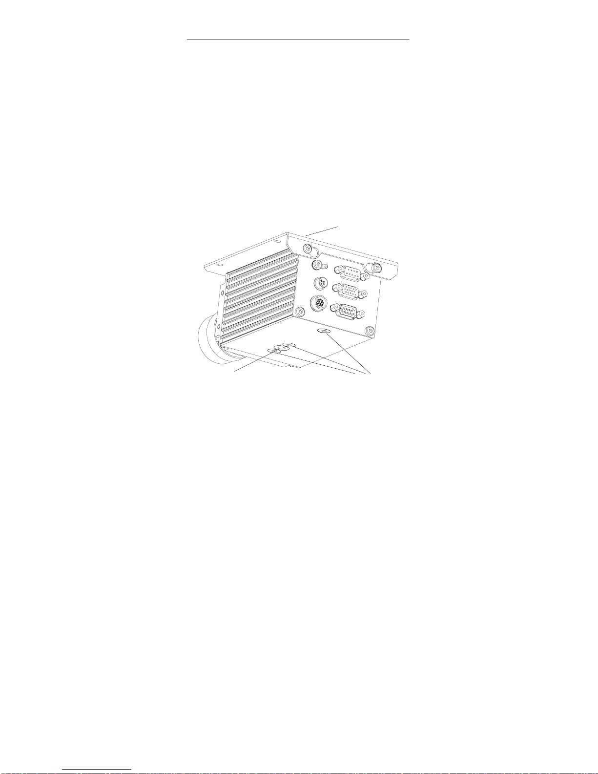
The VS 710 can be mounted in many different ways, making it highly
versatile and convenient to use.
A number of fixtures (1/4” support socket, M4 screw threads) for mounting
attachments are located on the underside of the metal casing.
Choose whichever mounting option best suits your needs:
• Directly onto the casing using the M4 screw threads
• To the support socket on the casing
• Using the mounting bracket supplied (not included in the VS 710 OEM
package)
Mounting bracket
M4 screw threads
1/4” support socket
Figure 1 Mounting Fixtures on the VS 710
Page 10

SIMATIC VS710
Quick Reference Guide
6
SIMATIC VS 710
A5E00032597-02
Dimensions, Mounting Fixtures
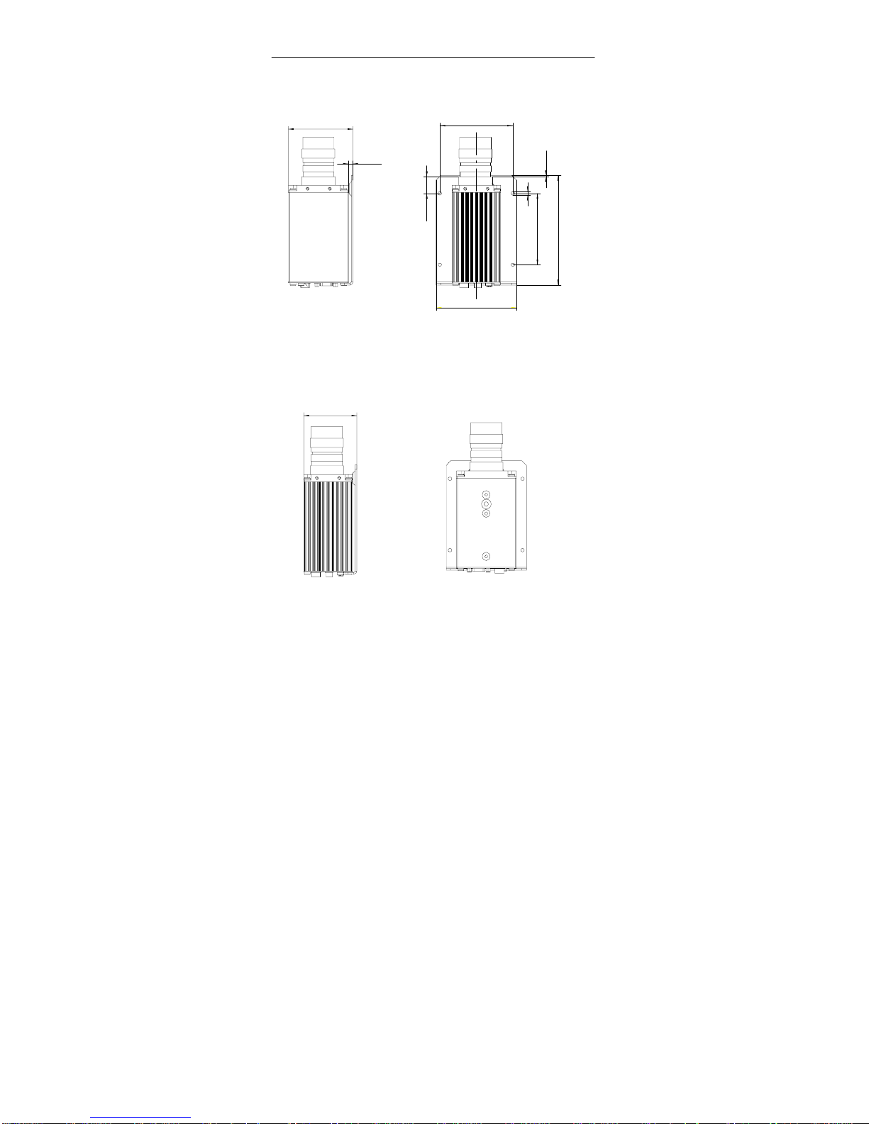
The dimensions are dependent on the type of mounting (with or without a
mounting bracket attached).
31
13.5
16.5
65
5
16.5
10
131.5
143
1.5
120
screw threads
on 3 sides
depth: 8mm
148
21.5
22.5
12.5
12.5
80.6
58
M4
M4
M4
American
coarse thread
1/4” 20 UNC
depth: 8mm
depth: 6mm
depth: 8mm
depth: 8mm
no mating connector
lens starts here
M4 8 mm deep
Figure 2 Dimensions with No Mounting Bracket Attached
Page 11
SIMATIC VS710Quick Reference Guide
SIMATIC VS 710
A5E00032597-02
7
6.3
86.6
98
96
5
22.5
1.5
147
108
Figure 3 Dimensions with a Mounting Bracket Attached (Side Mounting)
71
Figure 4 Dimensions with a Mounting Bracket Attached (Top Mounting)
Page 12
SIMATIC VS710
Quick Reference Guide
8
SIMATIC VS 710
A5E00032597-02
Mounting Bracket
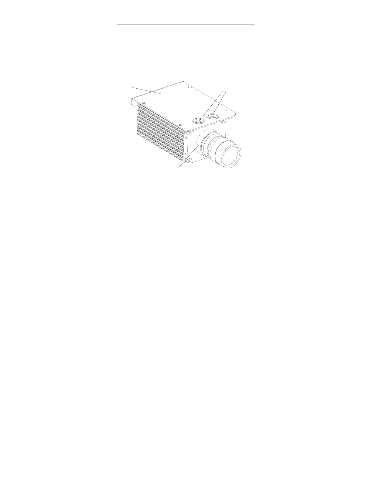
The mounting bracket snaps into place on top of the back panel and is
screwed tight on the front panel, leaving the other three sides of the casing
free for other mounting alternatives.
M 4 screws
Mounting bracket
set screw
1)
Figure 5 VS 710 with Mounting Bracket Attached
Lens Socket
The lens socket fits all commercial C-mount standard lenses.
1)
Note: the set screw on the lens socket is meant for factory settings
only. A readjustment of the lens position is not allowed.
Page 13

SIMATIC VS710Quick Reference Guide
SIMATIC VS 710
A5E00032597-02
9
2.3 Hardware Interfaces
The SIMATIC VS 710 has ports on the back panel for connecting up
peripherals (DP PROFIBUS, VGA, RS232, digital I/O) and the 24 volt
power supply. A terminal screw is in place for grounding.
The VS 710 has five interface ports.
• Round 4-pin plug for power supply (24 V, 500 mA) with a voltage
range of 20.4 to 28.8 V
• Round 12-pin plug with two 24-volt digital input points (including two
interrupt controllers), and four 24-volt digital optocoupler output
points (including a flash controller)
• 9-pin subminiature D connector PROFIBUS DP interface with a data
transmission rate of up to 12 Mbps.
• 3-row 15-pin subminiature D connector (SVGA monitor port)
• 9-pin subminiature D connector, RS232 interface, with a data
transmission rate of up to 115 Kbps
.
Grounding
Power supply connection
Digital I/O interface
DP interface
VGA interface
RS232 interface
Figure 6 Hardware Interfaces
Page 14
SIMATIC VS710
Quick Reference Guide
10
SIMATIC VS 710
A5E00032597-02
2.4 Power Supply - Connector Pinout
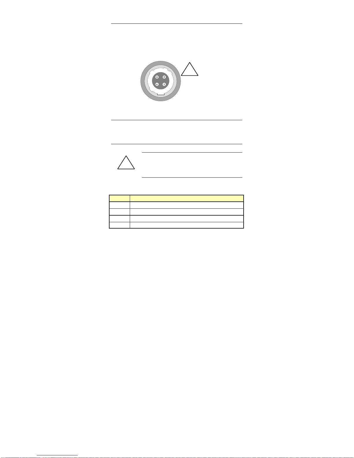
4-pin round connector pinout
!
PS
Figure 7 Power Supply - Connector Pinout
Note
The pin numbers are as seen on the rear casing with the unit in an upright
position.
!
Warning
VN= 24 VDC / 500 mA
(Voltage range: 20.4 to 28.8 volts)
The power supply connector has the following pinout:
Pin Signal
1 24 volts
2 24 volts
3 Ground
4 Ground
Maximum current per pin = 1 A.
The connector acts as a means of isolation from the 24-volt power supply.
Page 15

SIMATIC VS710Quick Reference Guide
SIMATIC VS 710
A5E00032597-02
11
24 VDC Power Supply
The entire supply must come from a 24 VDC safety extra-low voltage
(SELV) (operating voltage, load voltage, relay supply, etc.).
!
Warning
Personal injury or property damage can result.
If you do not connect the 24 VDC power supply to the
VS 710 correctly, components of your programmable
logic controller may be damaged and there is a risk of
personal injury.
The DC load power supply must fulfill the following
requirements:
Only extra-low voltage (DC 60 V) which is isolated
from the supply may be used as the load current power
supply. The protective separation can be achieved in
accordance with the requirements set out in VDE 0100
Part 410 / HD 384-4-41 / IEC 364-4-41 (as functional
extra-low voltage with protective separation), or
VDE 0805 / EN 60950 / IEC 950 (as safety extra-low
voltage (SELV)), or VDE 0106 Part 101.
Page 16
SIMATIC VS710
Quick Reference Guide
12
SIMATIC VS 710
A5E00032597-02
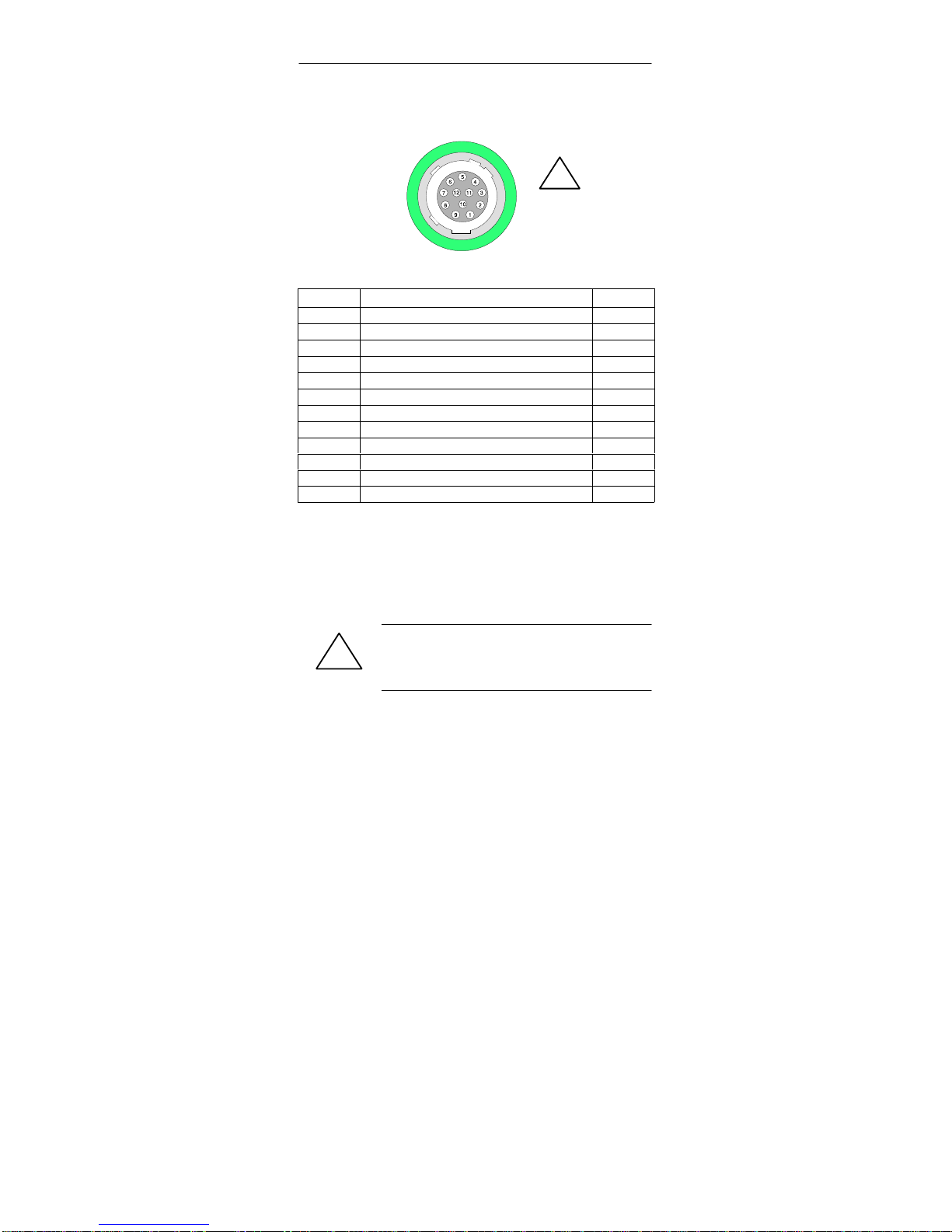
2.5 Digital Input / Output - Connector Pinout
12-pin round plug
Digital I/O
!
Figure 8 Digital Input / Output - Interface
Pin Signal Pin
1 24 volts L+
2 Ground 24 volts M
3 Digital output point 0 DO 0
4 Digital output point 1 DO 1
5 Digital output point 2 DO 2
6 Digital output point 3
1)
DO 3
7 Digital input point 0
2)
DI 0
8 Not assigned
9 Not assigned
10 24 volts L+
11 Ground 24 volts M
12 Digital input point 1
2)
DI 1
1
Simultaneous flash signal under ProVision
2
Triggering interrupt
• Maximum cable length 10 m, shielded
• 2 input points, optically isolated. All input points are referenced to a
common ground. Rated voltage: DC 24V
• 4 output points, optically isolated. All output points are referenced to a
common ground. Output current: 0.5 A. Rated load voltage DC 24 V
• Maximum current per pin = 1 A.
!
Warning
DI and D0 are galvanically coupled by ground pins 2 and 11.
DI 2x 24 VDC
DO 4x 24 VDC/0.5 A, P.D./RES, 5 W tungsten
Page 17
SIMATIC VS710Quick Reference Guide
SIMATIC VS 710
A5E00032597-02
13
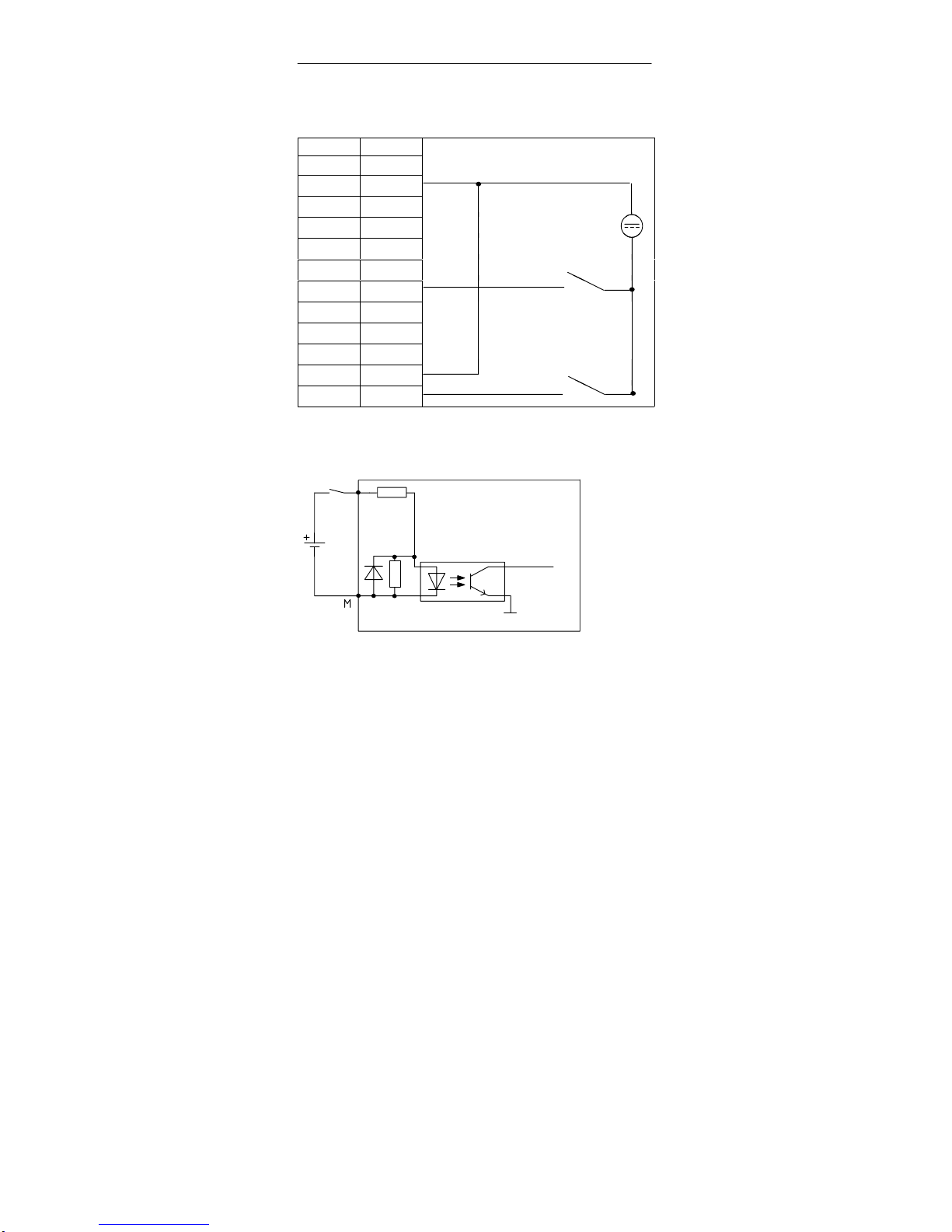
Wiring Diagram (Digital Input Points)
Pin
1 L+
M
2 M
M
3 DO 0
4 DO 1
5 DO 2
6 DO 3
DI 0
7 DI 0
DI 0
8
9
10 L+
11 M
12 DI 1
DI 1
Figure 9 Connection Diagram Showing Digital Input Points
Internal
Data Bus
M
internal
DI 0, DI 1
Figure 10 Basic Circuit Diagram Showing Digital Input Points
Page 18
SIMATIC VS710
Quick Reference Guide
14
SIMATIC VS 710
A5E00032597-02
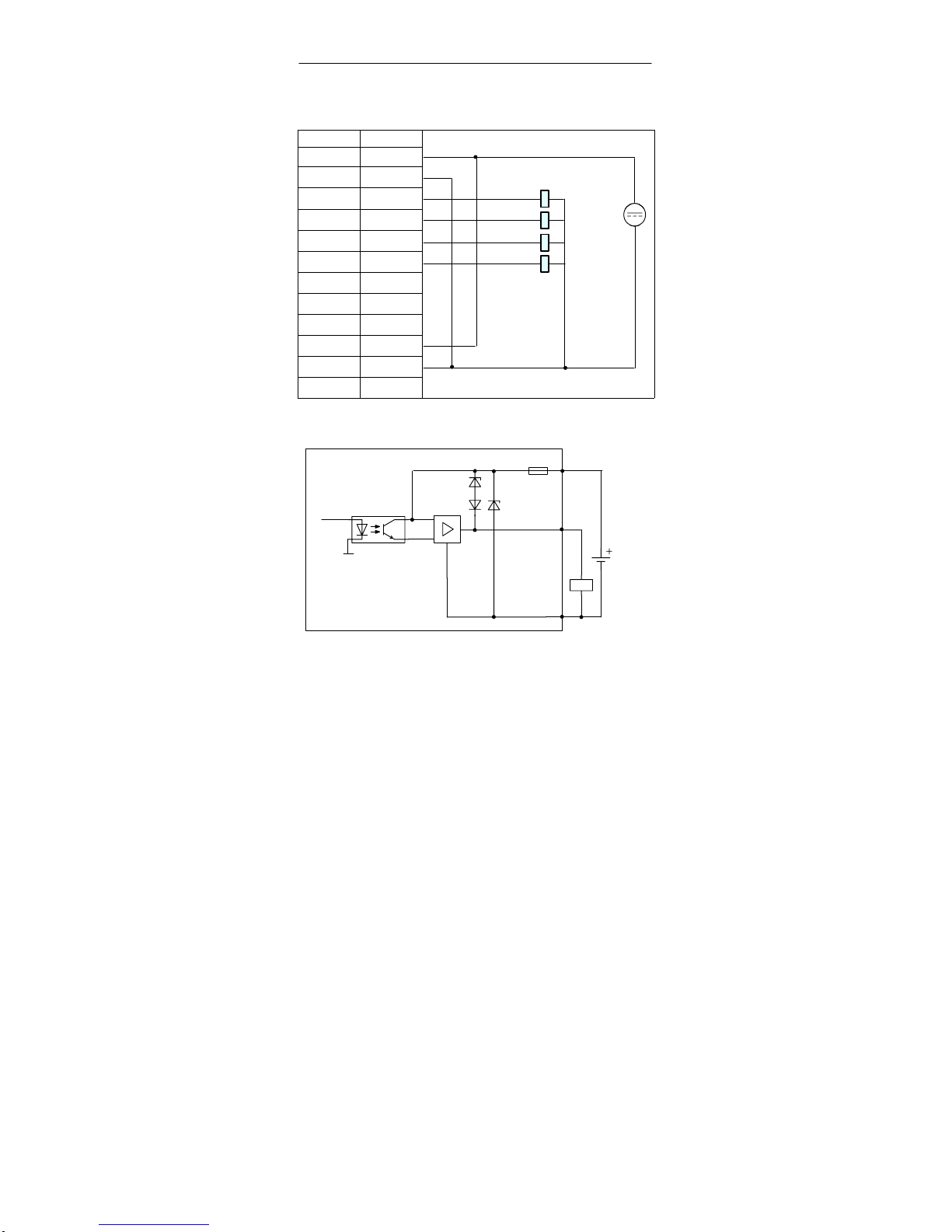
Wiring Diagram (Digital Output Points)
Pin
1 L+
L+
2 M
3 DO 0
DO 0
4 DO 1
DO 1
5 DO 2
DO 2
6 DO 3
DO 3
7 DI 0
8
9
10 L+
11 M
M
12 DI 1
Figure 11 Connection Diagram Showing Digital Output Points
L+
M
M
internal
Internal
Data Bus
DO...
Figure 12 Basic Circuit Diagram Showing Digital Output Points
Page 19
SIMATIC VS710Quick Reference Guide
SIMATIC VS 710
A5E00032597-02
15
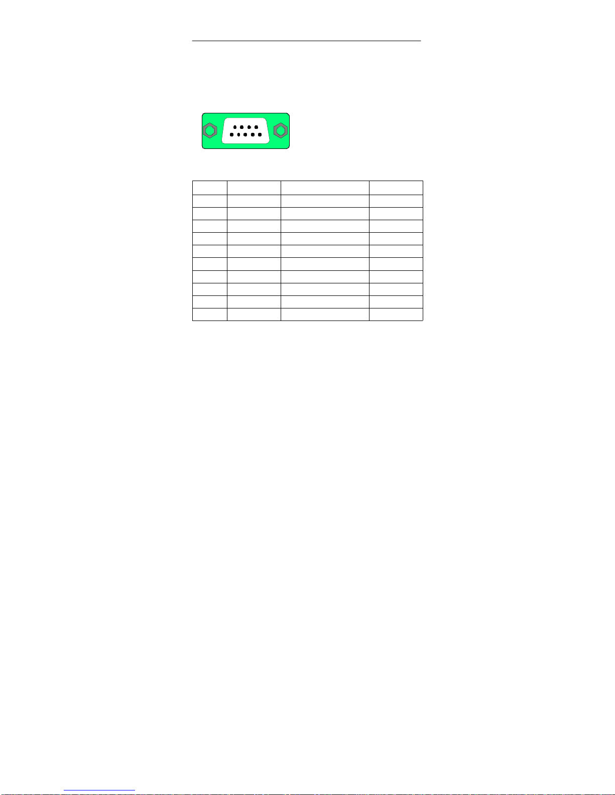
2.6 DP Connector Pinout
54321
9876
9-pin subminiature D connector
Figure 13 DP Interface
Pin Signal Function Input/Output
1 Not assigned - 2 Not assigned - 3 LTG_B Signal line B Input/output
4 RTSAS Request to send (PLC) 1) Output
5 M5
ext
GND (isolated) 2) Output
6 P5
ext
+5V (isolated) 3) Output
7 Not assigned
8 LTG_A Signal line A Output
9 Not assigned - Shield On connector casing
1
) Control signal for received data flow
The control is “1” active when the programmable controller is sending
2
) 0 V line of the 5 V power supply
3
)P5
ext
power supply (+5 V) of the 5 V power supply (powers bus
terminator)
The DP interface operates on the slave principle and is designed as a
floating interface. It has a maximum data transfer rate of 12 Mbps.
When using a point-to-point connection with a transmission rate of
12 Mbps, a line length of 100 m may be used.
Page 20
SIMATIC VS710
Quick Reference Guide
16
SIMATIC VS 710
A5E00032597-02
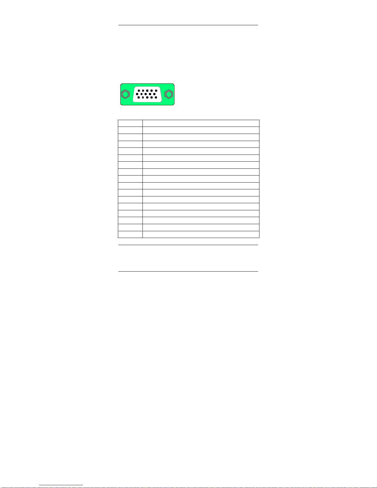
2.7 VGA Connector Pinout
You can connect a monitor to your VS 710 using the VGA socket
connector. The VGA socket connector has the following pinout:
54321
10
6
15141211 13
15-pin subminiature D connector
Figure 14
VGA Socket Connector
Pin Signal
1 Red
2 Green
3 Blue
4 Not assigned
5 Digital ground
6 Digital ground
7 Digital ground
8 Digital ground
9 Not assigned
10 Digital ground
11 Not assigned
12 Not assigned
13 Horizontal sync
14 Vertical sync
15 Not assigned
Shield On connector casing
Note
Connect your VGA monitor with the standard VGA cable.
The distance between monitor and VS 710 should not exceed 2.5 m.
Page 21
SIMATIC VS710Quick Reference Guide
SIMATIC VS 710
A5E00032597-02
17
2.8 RS232 Connector Pinout
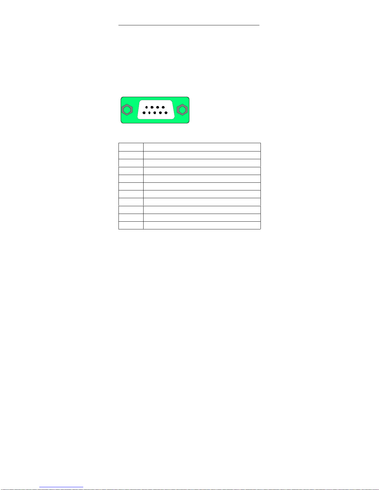
Use the RS232 interface to connect the VS 710 to your programming
device / PC. The RS232 connector on the VS 710 is a shielded 9-pin
subminiature D connector.
The RS232 connector has the following pinout:
54321
9876
9-pin subminiature D connector
Figure 15 RS232 Connector
Pin Signal
1 DCD (data carrier detect)
2 RXD (receive data)
3 TXD (transmit data)
4 DTR (data terminal ready)
5 Ground
6 DSR (data set ready)
7 RTS (request to send)
8 CTS (clear to send)
9 RI (ring indicator)
Shield On connector casing
The serial port is a fully-fledged RS232 interface. The ground pin is
referenced to the internal ground. The interface is configured as a COM1
port and can be addressed as such. The maximum line length is 10 m with a
transmission rate of 115 Kbps.
Page 22

SIMATIC VS710
Quick Reference Guide
18
SIMATIC VS 710
A5E00032597-02
Remote Keyboard and Remote Floppy via RS232
You can connect a host PC with a keyboard and diskette drive (floppy) to
the RS232 interface using a serial port cable (zero modem cable). The
Phoenix BIOS sets up a connection through this interface so that the host
keyboard and host diskette drive (read only) can be used as if they were
directly connected to the VS 710.
Note
You can use HOSTKEY to set up the connection with the host PC (see
Section 4.1).
2.9 IDE Flashdisk
The VS 710 enables you to use solid-state memory like a hard disk drive.
This “flashdisk” solid-state memory can be used to boot MS-DOS and store
application programs.
Note
The deleting and programming cycles per logical sector of the IDE
flashdisk are limited to 300,000 cycles due to physical properties.
Page 23

SIMATIC VS710Quick Reference Guide
SIMATIC VS 710
A5E00032597-02
19
3 Connecting the VS 710
3.1 Safety Recommendations
Qualified Personnel
Only qualified personnel should be allowed to install and work on this
equipment. Qualified persons in the context of this Quick Reference Guide
are defined as persons who are authorized to commission, to ground, and to
tag equipment, systems, and circuits in accordance with established safety
standards and regulations.
Correct Usage
Note the following:
!
Warning
This device may only be used for the applications described
in the catalog or the technical description, and only in
connection with devices or components from other
manufacturers which have been approved or recommended
by Siemens.
This product can only function properly and safely if it is
transported, stored, set up, and installed correctly, and
operated and maintained as recommended.
Cleaning the Unit
To clean the unit, use a soft cotton cloth and a mild, non-abrasive detergent.
Do not allow cleaning fluid or any other liquid to get inside the casing.
Note
The CCD sensor orifice must always be closed, either by the lens mounted
on top or by applying the dust cap supplied along with the product.
This precaution is necessary to avoid damaging the sensitive sensor
surface.
Page 24
SIMATIC VS710
Quick Reference Guide
20
SIMATIC VS 710
A5E00032597-02
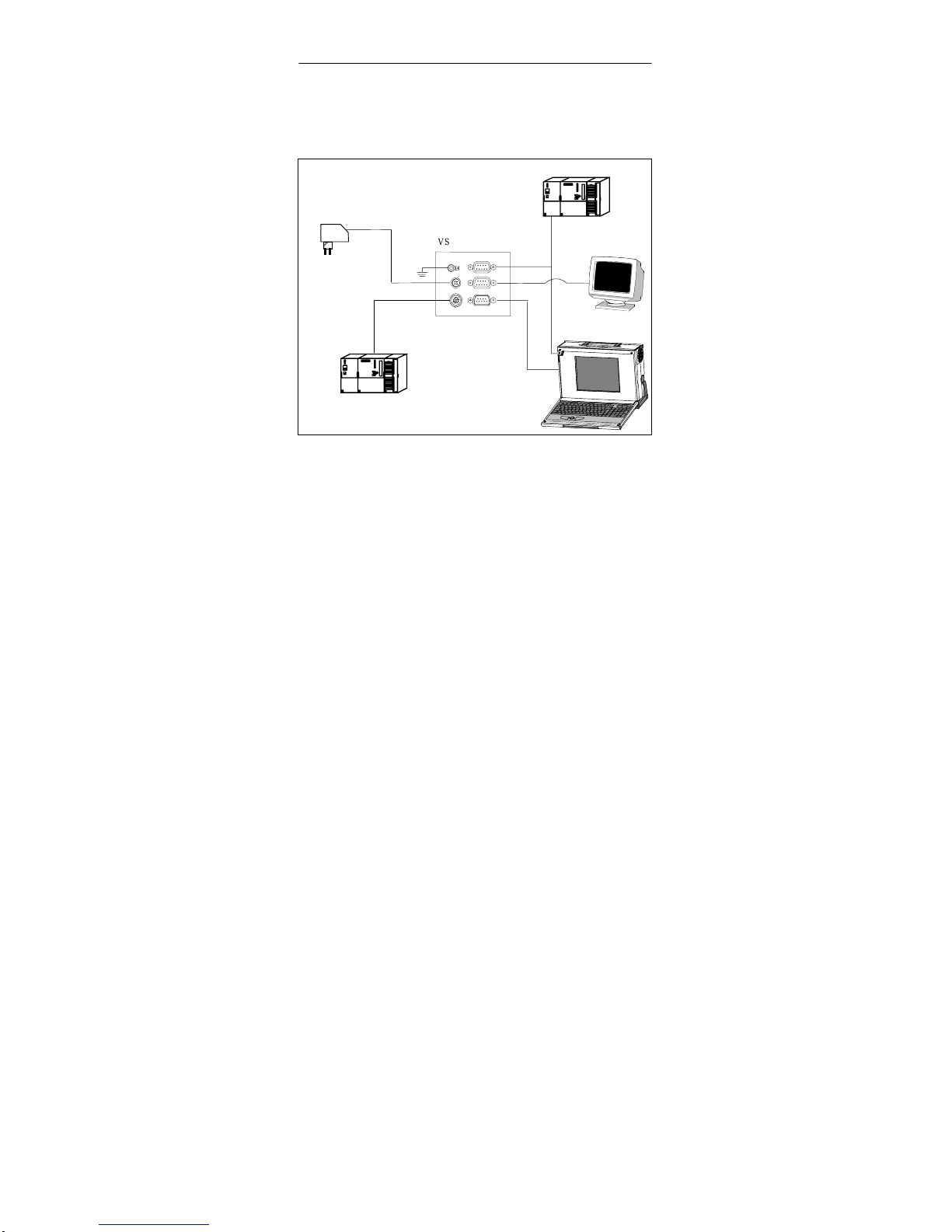
3.2 System Environment
VS 710 rear panel
SIMATIC S7
SIMATIC S7
24 V DC power supply unit
Monitor
Host PC /
programming
device
DIG. I/O
PS
DP
VGA
RS232
Figure 16 System Environment
The VS 710 operates in two basic modes:
1. Configure mode
The VS 710 is connected to a programming device / PC via RS232 or
PROFIBUS DP and is supplied with user programs and configuring
data.
2. Productive mode
The VS 710 is in the target operating mode and receives jobs (or
delivers processed data) through digital I/O, RS232, and
PROFIBUS-DP interfaces. It communicates with actuators / sensors,
control PCs, and PROFIBUS-DP master systems.
Page 25
SIMATIC VS710Quick Reference Guide
SIMATIC VS 710
A5E00032597-02
21
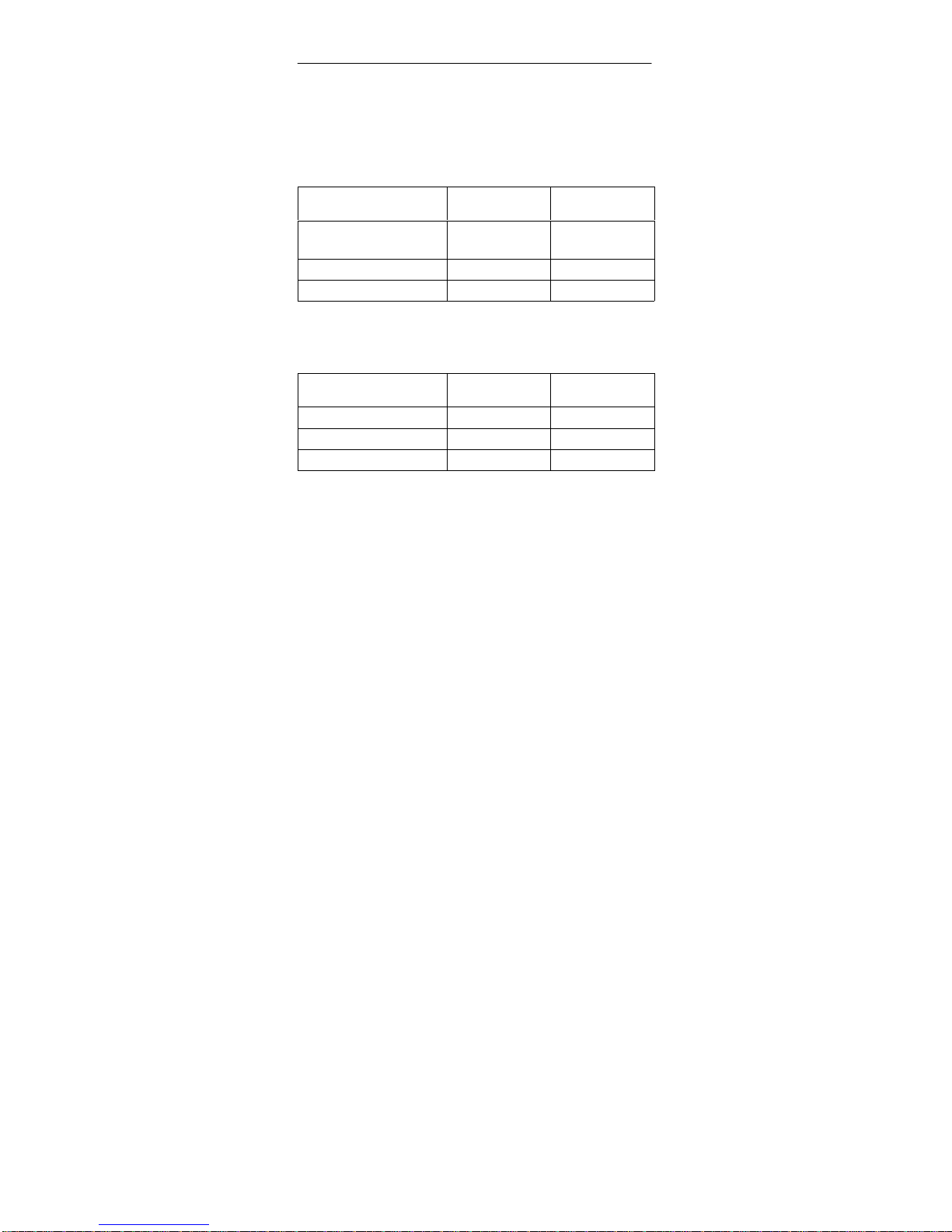
3.3 Connection Options
Function in Configure Mode
Connection via: VS 710
(with ProVision)
VS 710 OEM
RS232 interface Yes Yes
(with Hostkey)
DP interface Yes * No
Digital I/O Yes No
Function in Productive Mode
Connection via: VS 710
(with ProVision)
VS 710 OEM **
RS232 interface Yes Yes
DP interface Yes Yes
Digital I/O Yes Yes
* as of ProVision V2.0
** A suitable user program is required.
Page 26

SIMATIC VS710
Quick Reference Guide
22
SIMATIC VS 710
A5E00032597-02
4 Interactive Operation
4.1 Keyboard and Floppy Emulation
The VS 710 can be temporarily linked with the keyboard and diskette drive
of a separate PC / programming device (host PC) for operator control of the
VS 710. For this you need an RS232 connection, the emulation program
HOSTKEY.COM, and a VGA monitor connected to the VS 710.
HOSTKEY is started on DOS from Tool Diskette 1 on the host PC. Once
emulation has been started up, the interaction switches from the host PC to
the VS 710 (specifically, to the monitor). Tool diskette 1 can now be
removed and replaced by another diskette.
4.2 HOSTKEY Program
HOSTKEY emulates floppy diskette drive A: and the host PC keyboard as
components of the VS 710. For this you need a functioning serial
connection, and HOSTKEY must be activated before rebooting the VS 710.
The program is supplied on a diskette along with the product and is started
from the host PC.
The VS 710 monitor takes over the function of operator monitor once the
connection has been established.
1. Insert the HOSTKEY diskette in the diskette drive of the host PC,
having connected the host PC via the RS232 interface.
2. Start HOSTKEY from diskette drive A: at DOS level or from the DOS
box under Windows 95/98.
Note
You can also start HOSTKEY indirectly using the REMOTE.BAT
program. Before HOSTKEY starts using the maximum transmission rate,
you will explicitly be asked for a specific interface.
Note
The HOSTKEY.COM file is only to be run under the Windows 95,
Windows 98 and Windows ME operating systems.
The HSTKEYNT.EXE file is only to be run under the Windows NT and
Windows 2000 operating systems.
Page 27

SIMATIC VS710Quick Reference Guide
SIMATIC VS 710
A5E00032597-02
23
Setup Options
You can call HOSTKEY in a number of ways, as the following table
shows.
Syntax:
HOSTKEY [/?] [/Cx] [/Sxx] [/NOF] [/V]
Option Explanation
/? This screen
/C1 COM1
/C2 COM2
/S96 9600 bps
/S192 19200 bps
/S384 38400 bps
/S576 57600 bps
/S1152 115200 bps
/NOF Do not check for floppy disk when loading
HOSTKEY
/V Verbose mode, display HOSTKEY messages
Call without specifying
parameters
Activates the COM1 interface with a rate of
115.2 Kbps
Operator Input to HOSTKEY
Once emulation has been started, key commands go to the VS 710.
Exceptions are:
– CTRL-X Aborts HOSTKEY
– CTRL-Alt-F10 Reboots the VS 710
Page 28
SIMATIC VS710
Quick Reference Guide
24
SIMATIC VS 710
A5E00032597-02
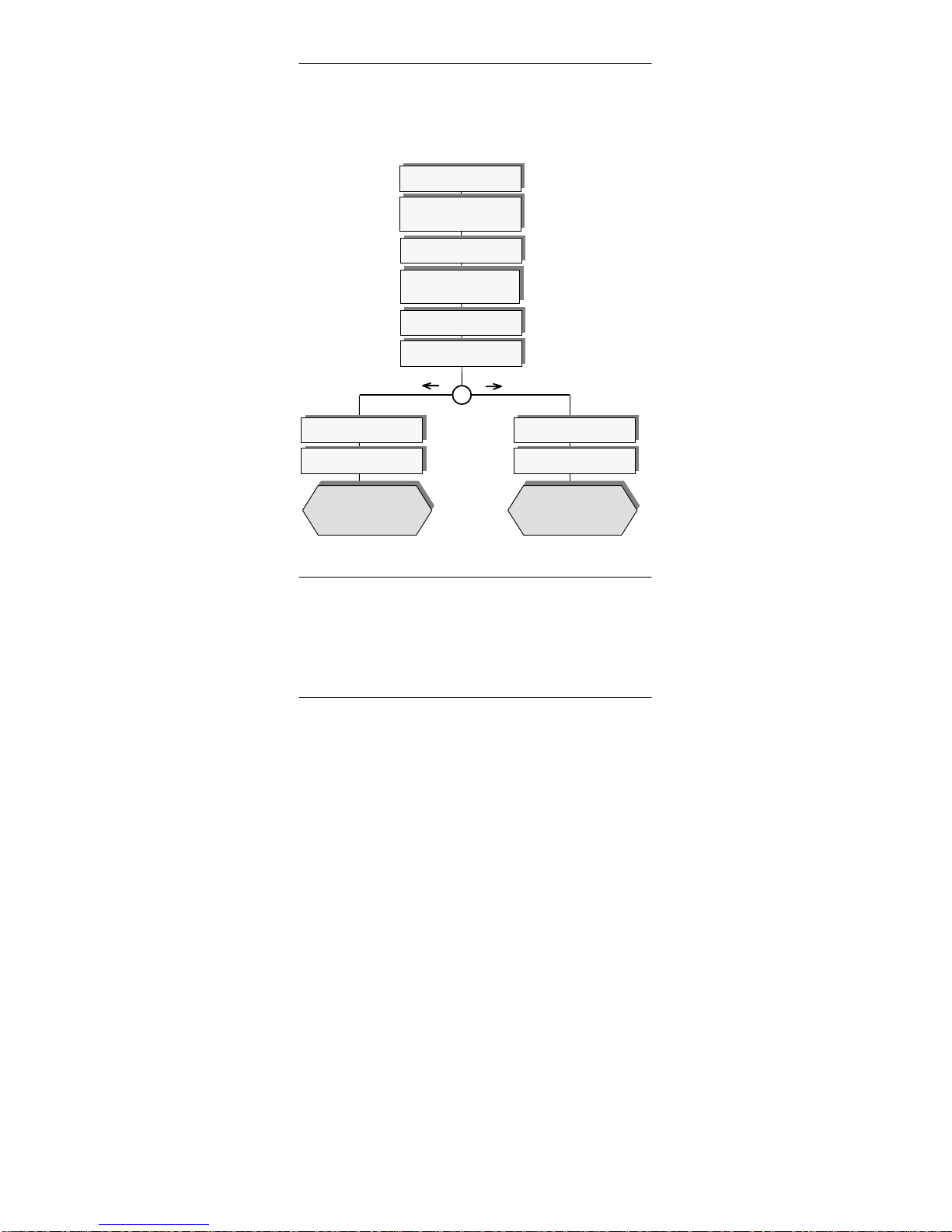
4.3 Operating DOS 6.22 and SETUP
The following steps will take you to the VS 710 operator level you require:
Switch off VS 710
Connect VGA monitor to
VS 710
Insert Tool Diskette 1 in
the diskette drive of the
host PC
Start HOSTKEY or
REMOTE.BAT from drive A:
Switch on VS 710
Establish RS232 cable
connection between the
host PC and VS 710
To end remote control of
the VS 710:
CTRL-ALT-F10: reboot
CTRL-X: exit
To boot up the VS 710
internal drive C:
Remote control of VS 710
from host PC
Perform SETUP functions
To reboot the VS 710:
Press Ctrl-Alt-F10
Press F2 to start SETUP
Go to MS-DOS
Go to SETUP
Figure 17 Using HOSTKEY to Operate the VS 710
Note
- To avoid taking up too much memory, only a minimal subset of DOS 6.22 is
loaded on the VS 710. Other DOS utilities are available on Tool Diskette 1.
- You cannot copy files from VS 710 back onto a diskette while emulation is in
progress. To do so, try starting INTERSVR.EXE from a suitable
AUTOEXEC.BAT (startup file).
- Time and date settings are lost if the VS 710 is de-energized; for example, if the
power supply fails or if you pull the plug. Backups are not made.
Page 29
SIMATIC VS710Quick Reference Guide
SIMATIC VS 710
A5E00032597-02
25
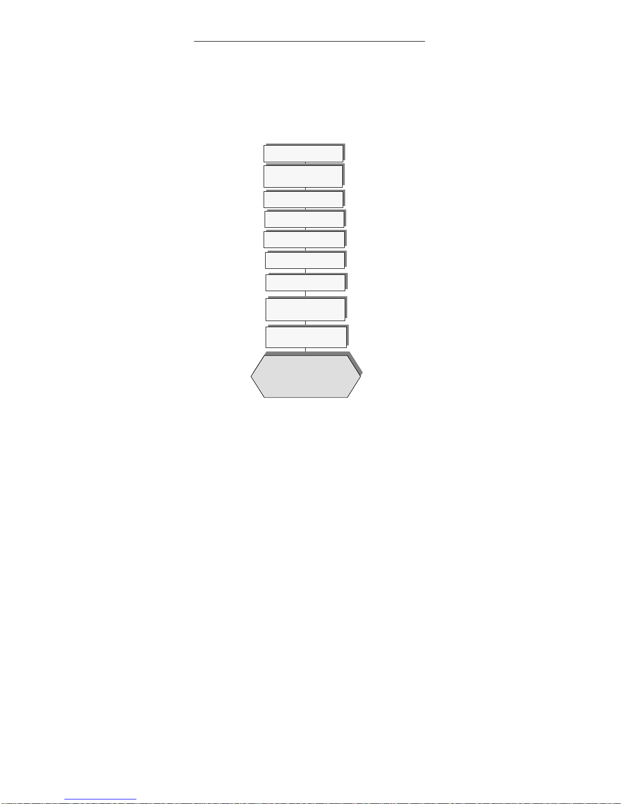
4.4 Installing older ProVision versions on Your
VS 710
To install or update the ProVision Runtime System (<V2.1), proceed as
indicated below. Use 1.44 Mbyte diskettes that have been loaded with the
relevant files, for example as described in ProVision Setup
(see ProVision Product Information for further details).
Switch off the VS 710
Plug the VGA monitor
into the VS 710
Type in A:\Install 1
Switch on the VS 710
Connect the host PC and
VS 710 via the RS232
interface
Watch out for system messages
(such as “Change diskette”)
Installation complete.
Press Ctrl-Alt-F10 key
combination to restart VS 710.
Press Ctrl-X to exit Hostkey
Type in A:\install 1 to
delete old files and load
new files from A: to C:
Insert diskette 1 in the diskette
drive of the host PC
Wait until MS-DOS prompts
with C:\
Figure 18 Installing ProVision
The VS 710 must be reset in order to restart it. The remote connection must
be disconnected on startup, either by removing the RS232 connection or by
exiting HOSTKEY. If the connection is not disconnected, ProVision does
not restart and VS 710 returns to the installation mode.
Page 30
SIMATIC VS710
Quick Reference Guide
26
SIMATIC VS 710
A5E00032597-02
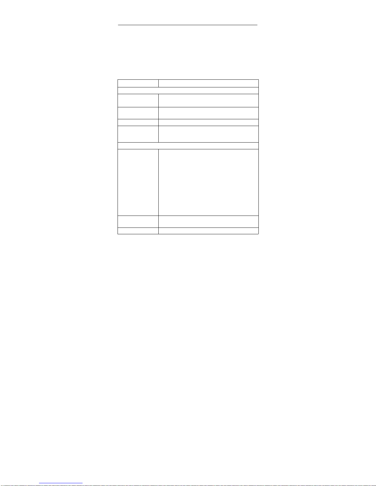
5 Technical Specifications
This table contains the complete technical specifications for the VS 710.
5.1 General Specifications
Characteristic Technical Specifications
VS 710
Order Number SIMATIC VS 710: 6GF 1710-3AA
SIMATIC VS 710 (OEM): 6GF 1710-2AA
Dimensions 65 x 80 x 130 mm (W x H x D) with no mounting
bracket attached
Weight Approx. 0.750 kg (without lens)
Interfaces
to S7/M7/C7
to PC
RS485 (12 Mbps)
RS232 (115 Kbps)
Power Supply
Supply voltage (VN)
S Input voltage
protected
against polarity
reversal
S Voltage
interruption
(can be
jumpered)
24 VDC; (20.4 to 28.8 VDC, safety extra low voltage,
SELV). The VS 710 has no integrated protection
against high-energy surge pulses in the µs range (surge
pulse). See EMC for external measures.
Yes
≥ 20 ms
Current
consumption (I
N
)
I=480 mA (typ)/600 mA (max.)
Starting current I1 max. 10 A; 1 ms
Page 31

SIMATIC VS710Quick Reference Guide
SIMATIC VS 710
A5E00032597-02
27
Characteristic Technical Specifications
Load Current Power Supply
Supply voltage (VN)
S Input voltage
protected
against polarity
reversal
24 VDC; (20.4 to 28.8 VDC, safety extra-low voltage,
SELV). The VS 710 has no integrated protection
against high-energy surge pulses in the µs range (surge
pulse). See EMC for external measures.
Yes
Protection class IP40
Safety
Requirements
According to
IEC 1131-2 ¢ EN 61131-2
Electromagnetic Compatibility (EMC)
Emitted interference
Limit value class B according to EN55022 ¢ CISPR 22
Conducted
interference on
direct voltage
supply lines
±2 kV (according to IEC 1000-4-4; burst)
±1 kV (according to IEC 1000-4-5; µs pulse
/ line to line)
*
±2 kV (according to IEC 1000-4-5; µs pulse
/ line to ground)
*
*
With protective element lightning conductor KT
type AD 24 V from the Dehn company.
Noise immunity on
signal lines
±2 kV (according to IEC 1000-4-4; burst)
±2 kV (according to IEC 1000-4-5;
µs pulse / line to ground)
Noise immunity
against discharge of
static electricity
±6 kV, discharge on contact
(according to IEC 1000-4-2; ESD)
±8 kV, atmospheric discharge
(according to IEC 1000-4-2; ESD)
Immunity to
high-frequency
radiation
10 V With 80% amplitude modulation with 1 kHz,
10 kHz - 80 MHz
(according to IEC 1000-4-6)
10 V/m With 80% amplitude modulation with 1 kHz,
80 kHz - 1 GHz (according to IEC 1000-4-3)
10 V/m Pulse-modulated 50 % IED with 900 MHz
(according to EN 50 204)
Page 32

SIMATIC VS710
Quick Reference Guide
28
SIMATIC VS 710
A5E00032597-02
Characteristic Technical Specifications
Climatic Conditions
Temperature
S Operation
S Storage/trans-
port
Tested according to IEC 68-2-1, IEC 68-2-2
± 0 °C to + 50 °C
Rate of temperature change max. 10 °C/h
-20 °C to +70 °C
Rate of temperature change max. 20 °C/h
Relative humidity
S Operation
S Storage/trans-
port
Tested according to IEC 68-2-3
5% to 95% at 25°C (no condensation)
5% to 95% at 25°C (no condensation)
Atmospheric
pressure
S Operation
S Storage/trans-
port
1080-795 hPa (¢ -1000 m to +2000 m)
1080-660 hPa (¢ -1000 m to +3500 m)
Mechanical Environmental Conditions (without lens)
Vibration
S Operation
S Storage/trans-
port
Tested according to IEC 68-2-6
10 to 58 Hz, amplitude 0.075 mm
58 to 500 Hz, acceleration 9.8 m/s
2
5 to 9 Hz, amplitude 3.5 mm
9 to 500 Hz, acceleration 9.8 m/s
2
Shock
S Operation
S Storage/trans-
port
Tested according to IEC 68-2-27/29
Semi-sinusoidal: 100 m/s
2
(10 g),
16ms, 100 shocks
Semi-sinusoidal: 700 m/s2 (70 g),
6ms, 3 shocks
Semi-sinusoidal: 250 m/s2 (25 g),
6ms, 1000 shocks
Note
The absolute brightness values of the image may vary slightly, depending
on the physical properties of the CCD chip and the temperature range.
Page 33
SIMATIC VS710Quick Reference Guide
SIMATIC VS 710
A5E00032597-02
29
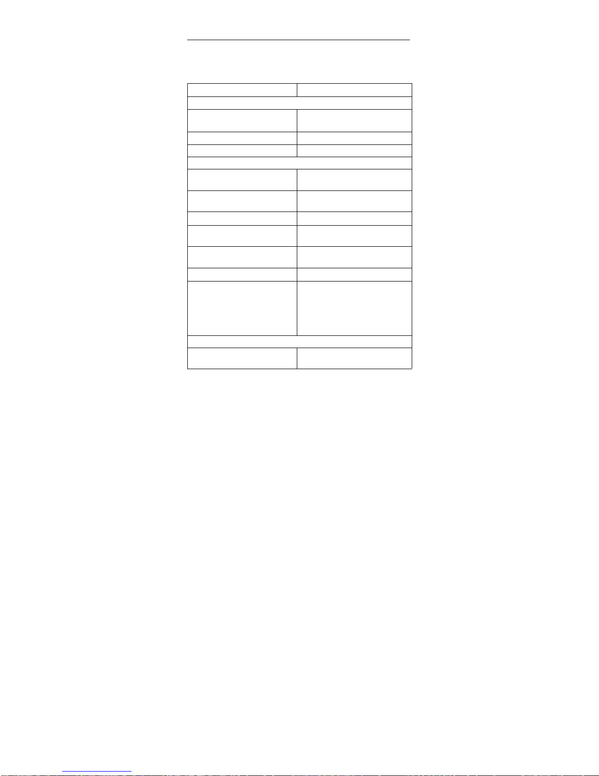
5.2 Digital I/O Interface
Characteristic Technical Specifications
Module-Specific Data
Number of inputs 2
Number of outputs 4
Line length, shielded 10 m
Current, Voltages, Potentials
Rated voltage
Load current supply L+
24 VDC
Permitted rated voltage
Load current supply L+
20.4 V to 28.8 V
Current consumption L+ Depends on assignment
Number of simultaneously
controllable inputs
2
Number of simultaneously
controllable outputs
4
Isolation Yes (optocoupler)
Permitted potential differences
S Between M connections
S Between input (M connection)
and central grounding point
S Isolation tested with
500 VDC
Interrupt
Interrupt Digital inputs 0 and 1 have interrupt
capability
Page 34

SIMATIC VS710
Quick Reference Guide
30
SIMATIC VS 710
A5E00032597-02
Characteristic Technical Specifications
Data for Selecting a Sensor
Input voltage
S Rated value
S With signal “1”
S With signal “0”
24 VDC
From 11 to 30 V
-3 V to +5 V
Input current
S With signal “1”
From 4 mA to 8 mA
Input delay time 10 µs
Data for Selecting an Actuator
Output voltage
S With signal “1”
S With signal “0”
L+-1.5 v
Max. 3 V
Output current
S With signal “1” rated value
permitted range
S With signal “0” (residual cur-
rent)
0.5 A
From 5 mA to 0.6 A
Max. 0.1 mA
Load on lamps Max. 5 W
Parallel connection of 2 outputs No
Maximum operating frequency:
S With ohmic load/lamp load
S With inductive load
500 Hz
2.0 Hz at 0.5 A
Switching delay Max. 400 µs
Limit (internal) of voltage induced
on circuit interruption
L+-39 V
Short-circuit protection at output Electronic
Page 35
SIMATIC VS710Quick Reference Guide
SIMATIC VS 710
A5E00032597-02
31
6 Certification
6.1 Certification for the USA and Canada
UL/CSA Certification
Important for USA and Canada:
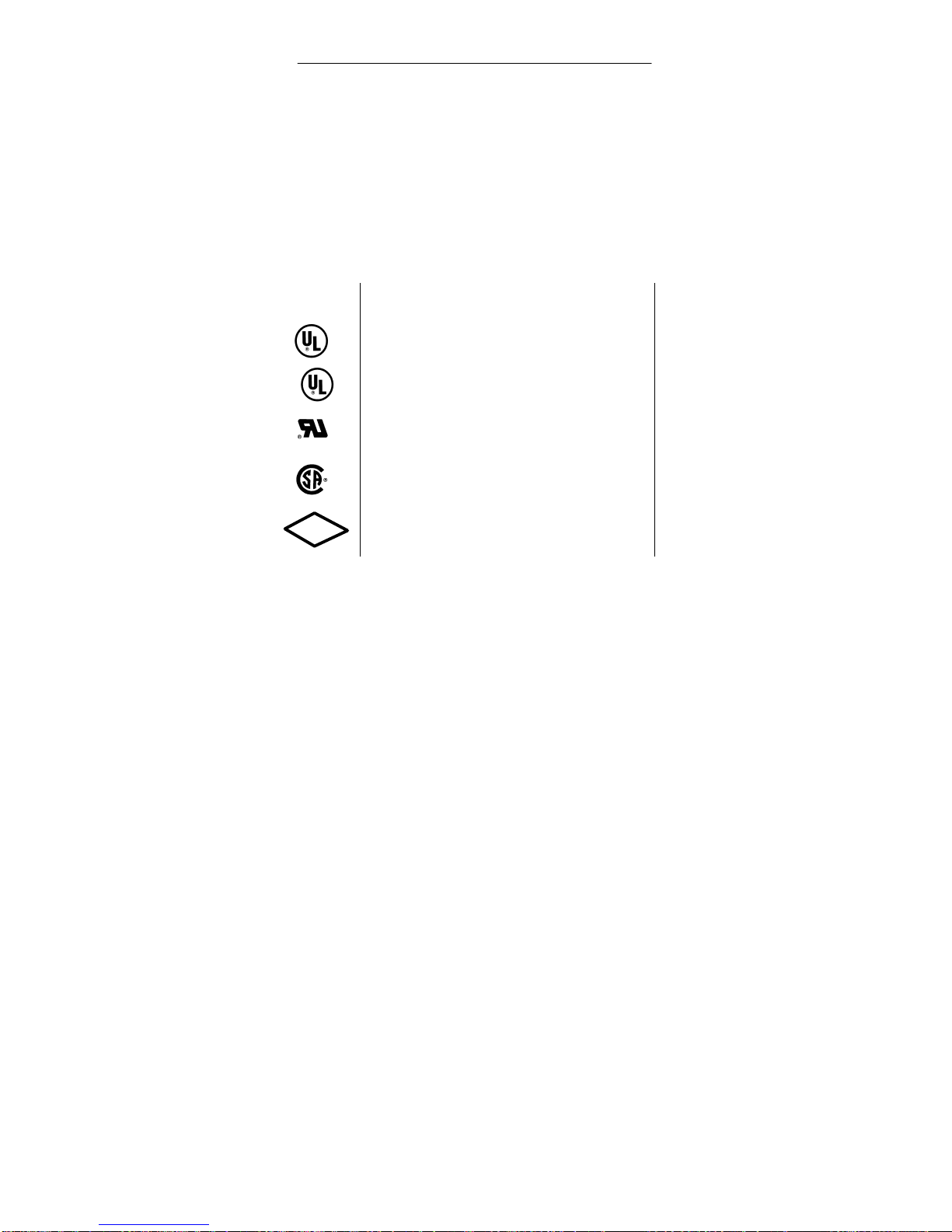
Symbols on the device like those shown below mean that approval has been issued as indicated:
Underwriters Laboratories (UL) in accordance with Standard
UL 508
Underwriters Laboratories (UL) in accordance with Canadian
Standard C22.2 No. 142
UL Recognition Mark
Canadian Standard Association (CSA) in accordance with Standard C22.2 No. 950 or C22.2 No. 142
FM approval in accordance with Factory Mutual Approval
Standard Class Number 3611, 3600, 3810 Class I, Division 2,
Group A, B, C, D.
C
FM
APPROVED
Page 36

SIMATIC VS710
Quick Reference Guide
32
SIMATIC VS 710
A5E00032597-02
FM Approval
FM Approval pursuant to Factory Mutual Approval Standard Class
Number 3611, Class I, Division 2, Group A, B, C, D.
!
Warning
Personal injury or property damage can result.
Unless the location is known to be non-hazardous, do not
connect or disconnect (plugs, fuses, switches, etc) while the
unit is in operation as physical injury and damage to
property may result.
Do not connect or disconnect live circuits unless the location
is known to be non-hazardous.
!
Warning
WARNING - DO NOT DISCONNECT WHILE CIRCUIT
IS LIVE
UNLESS LOCATION IS KNOWN TO BE
NON-HAZARDOUS
Page 37
SIMATIC VS710Quick Reference Guide
SIMATIC VS 710
A5E00032597-02
33
6.2 Certification for Europe
EMC Guidelines
The following applies to the SIMATIC product described in this Quick
Reference Guide:
This product fulfills the requirements for the EC directive
89/336/EEC on “electromagnetic compatibility” and the
following fields of application apply according to this EC
symbol:
Field of Application
Requirement for
Emitted Interference Immunity to
Interference
Residential,
commercial and light
industry
EN 50081-1: 1992 EN 50082-1: 1992
Industry EN 50081-2: 1993 EN 50082-2: 1995
Declaration of Conformity
In accordance with Section 10 (2) of the above EU Directive, the EU
Declaration of Conformity and related documents will be held available for
inspection by the competent authorities at:
Siemens Aktiengesellschaft
Bereich Automatisierungs- und Antriebstechnik
A&D AS RD 4
Postfach 1963
D-92209 Amberg
Germany
Observing the Setup Guidelines
The setup guidelines and notes on safety given in the documentation must
be observed during startup and when operating the device.
Page 38

SIMATIC VS710
Quick Reference Guide
34
SIMATIC VS 710
A5E00032597-02
 Loading...