

Siemens SIMATIC VS130 Series Manual

Preface, Co ntents
SIMATIC
Vision Sensor VS 130
Manual
Product Overview
System Integration
Installation
Putting into Operation
Operator Functions
Controlling with a PLC
Diagnostics
Appendix
Index
1
2
3
4
5
6
7
A
Edition 03/2003
A5E00199459-01

Safety Guidelines
This manual contains notices intended to ensure personal safety, as well as to protect the products and
connected equipment against damage. These notices are highlighted by the symbols shown below and
graded according to severity by the following texts:
!
!
!
Danger
indicates that death, severe personal injury or substantial property damage will result if proper
precautions are not taken.
Warning
indicates that death, severe personal injury or substantial property damage can result if proper
precautions are not taken.
Caution
indicates that minor personal injury can result if proper precautions are not taken.
Caution
indicates that property damage can result if proper precautions are not taken.
Notice
draws your attention to particularly important information on the product, handli ng the product , or t o a
particular part of the documentation.
Qualified Personnel
Only qualified personnel should be allowed to install and work on this equipment. Qualified persons are
defined as persons who are authorized to commission, to ground and to tag circuits, equipment, and
systems in accordance with established safety practices and standards.
Correct Usage
Note the following:
Warning
!
Trademarks
Copyright © Siemens AG 2003 All rights reserved
The reproduction, transmission or use of this document or its
contents is not permitted without express written authority.
Offenders will be liable for damages. All rights, including rights
created by patent grant or registration of a utility model or design,
are reserved.
Siemens AG
Bereich Automation and Drives
Geschaeftsgebiet Industrial Automation Systems
Postfach 4848, D- 90327 Nuernbe rg
Siemens Aktiengesellschaft A5E00199459-01
This device and its components may only be used for the applications described in the catalog or the
technical description, and only in connection with devices or components from ot her manufact urers
which have been approved or recommended by Siemens.
This product can only function correctly and safely if it is transported, stored, s et up, and install ed
correctly, and operated and maintained as recommended.
SIMATIC®, SIMATIC HMI® and SIMATIC NET® are registered trademarks of SIEMENS AG.
Third parties using for their own purposes any other names in this document which refer to trademarks might
infringe upon the rights of the trademark owners.
Disclaimer of Liability
We have checked t he contents of this manual for agreemen t with
the hardware and s oftware described. Since de viations cannot be
precluded entirel y, we cannot guarantee full a greement. However,
the data in this m anual are reviewed regul arly and any necessary
corrections included in subsequent editions. Suggestions for
improvement are welcom e d.
©Siemens AG 2003
Technical data subject to change.

Preface
Purpose of the Manual
This manual describes Vision Sensors SIMATIC VS 130. It supports you during
theinstallation, commissioning and operation of the Sensors.
The manual is intended for persons working in the fields of programming,
configuration, commissioning, servicing programmable logic controllers and image
processing devices.
Guide
For easy and fast access of special information, the manual contains the following
access aids:
• At the beginning of the manual you will find a complete table of contents.
• At the end of the manual you will find a comprehensive index which gives you
rapid access to the information you need.
• In the chapters, you will find information that gives you an overview of the
contents of the section on the left column of every chapter.
Additional Information
An installation instruction manual in paper form is supplied for the installation and
wiring of the product.
You will find a "Getting Started" on the CD supplied for the first commissioning of
SIMATIC VS 130.
Additional Support
If you have questions on how to use the products described in this manual that are
not answered here, please contact your local Siemens dealer or office.
http://www.siemens.com/automation/partner
Vision Sensor VS 130
A5E00199459-01
iii

Preface
A&D Technical Support
Worldwide, available 24 hours a day:
Nuernberg
Johnson City
Beijing
Worldwide (Nuernberg)
Technical Support
24 hours a day, 365 days a year
Phone: +49 (0) 180 5050-222
Fax: +49 (0) 180 5050-223
E-Mail: adsupport@
siemens.com
GMT: +1:00
Europe / Africa (Nuernberg)
Authorization
Local time: Mon.-Fri. 8:00 to 17:00
Phone: +49 (0) 180 5050-222
Fax: +49 (0) 180 5050-223
E-Mail: adsupport@
siemens.com
GMT: +1:00
The languages of the SIMATIC Hotlines and the authorization hotline are generally German and English.
United States (Johnson City)
Technical Support and
Authorization
Local time: Mon.-Fri. 8:00 to 17:00
Phone: +1 (0) 423 262 2522
Fax: +1 (0) 423 262 2289
E-Mail: simatic.hotline@
sea.siemens.com
GMT: -5:00
Asia / Australia (Beijing)
Technical Support and
Authorization
Local time: Mon.-Fri. 8:00 to 17:00
Phone: +86 10 64 75 75 75
Fax: +86 10 64 74 74 74
E-Mail: adsupport.asia@
siemens.com
GMT: +8:00
Vision Sensor VS 130
iv A5E00199459-01

Service & Support on the Internet
In addition to our documentation, we offer our Know-how online on the internet at:
http://www.ad.siemens.de/support
where you will find the following:
• Current Product Information leaflets, FAQs (Frequently Asked Questions),
Downloads, Tips and Tricks.
• A newsletter giving you the most up-to-date information on our products.
• The Knowledge Manager helps you find the doc uments you need.
• Users and specialists from all over the world share information in the forum.
• Your local customer service representative for Automation & Drives in our
customer service representative data bank.
• Information on field service, repairs, spare parts and more under "Services".
Preface
Vision Sensor VS 130
A5E00199459-01
v

Preface
Vision Sensor VS 130
vi A5E00199459-01

Contents
1 Product Overview 1-1
1.1 Product Description...........................................................................................1-1
1.2 Components......................................................................................................1-3
1.3 Processing Setup.............................................................................................. 1-4
1.4 Important Requirements for Installation............................................................1-5
1.5 Applications.......................................................................................................1-5
2 System Integration 2-1
2.1 Configuration.....................................................................................................2-1
2.2 Application Examples........................................................................................2-2
2.2.1 Reading Codes in Stand-alone Mode...............................................................2-2
2.2.2 Reading and Comparing Codes in Standalone Mode ......................................2-3
2.2.3 Reading Codes in a PROFIBUS Environment..................................................2-4
2.3 Including the Vision Sensor VS 130 in HW Config ...........................................2-5
3 Installation 3-1
3.1 Installing Components.......................................................................................3-1
3.2 Wiring Components...........................................................................................3-3
3.3 Guidelines on Preventing Electrical Interference..............................................3-5
3.4 Guidelines for Use of PROFIBUS DP...............................................................3-5
4 Putting into Operation 4-1
4.1 Turning on the Device.......................................................................................4-1
4.1.1 Control and Display Panel.................................................................................4-2
4.2 Adjusting the Sensor with the Setup Software..................................................4-4
5 Operator Functions 5-1
5.1 Overview ...........................................................................................................5-1
5.2 Menus of the "RUN" Menu Level ......................................................................5-2
5.2.1 "Code" Menu.....................................................................................................5-2
5.2.2 "STOP" Menu....................................................................................................5-2
5.2.3 "Info" Menu........................................................................................................5-3
5.3 Menus of the STOP Menu Level.......................................................................5-5
5.3.1 "Train" Menu......................................................................................................5-5
5.3.2 "RUN" Menu......................................................................................................5-7
5.3.3 "Adjust" Menu....................................................................................................5-7
5.3.4 "Settings" Menu.................................................................................................5-9
5.3.5 "Delete" Menu .................................................................................................5-14
Vision Sensor VS 130
A5E00199459-01
vii

Contents
6 Controlling with a PLC 6-1
6.1 Control via the I/O Interface "DI/DO".................................................................6-1
6.1.1 Control Signals..................................................................................................6-1
6.1.2 Selecting the Mode............................................................................................6-2
6.2 Control via the "PROFIBUS DP" Interface........................................................6-6
6.2.1 Principle of Data Transmission via PROFIBUS DP ..........................................6-6
6.2.2 Assignment of the Interface of the Processing Unit with Relevance for
PROFIBUS DP..................................................................................................6-7
6.2.3 Sample Program for Data Exchange, if Code Length %\WHV.....................6-8
6.2.4 Consistent Data Transmission........................................................................6-10
7 Diagnostics 7-1
7.1 Introduction........................................................................................................7-1
7.2 Diagnostics with Messages...............................................................................7-1
7.2.1 Error Messages.................................................................................................7-2
7.2.2 Warnings/Notes.................................................................................................7-5
7.2.3 Read Results.....................................................................................................7-5
7.3 Diagnostics Based on the "BF" LED .................................................................7-6
7.4 Slave Diagnostics..............................................................................................7-7
7.4.1 Introduction........................................................................................................7-7
7.4.2 Reading Out the Diagnostic Information with S 7 .............................................7-7
7.4.3 Structure of the Slave Diagnostic Data.............................................................7-8
A Appendix A-1
A.1 Components of the Produc t ............................................................................. A-1
A.2 Technical Specifications................................................................................... A-3
A.2.1 Vision Sensor SIMATIC
®
VS 130.....................................................................A-3
A.2.2 General Data....................................................................................................A-5
A.2.3 Interface Digital Inputs/Outputs........................................................................A-8
A.3 Certifications, Standards , and Ap prov als......................................................... A-9
A.4 Installation Dimensions.................................................................................. A-10
A.5 Interface Assignment of the Processing Unit................................................. A-12
A.6 Wiring Suggestions ........................................................................................ A-15
A.7 Setup Software for SIMATIC VS 130............................................................. A-17
A.7.1 Requirements.................................................................................................A-17
A.7.2 Preparations...................................................................................................A-17
A.7.3 Displaying Images to Adjust the Sensor Head...............................................A-19
Index
Vision Sensor VS 130
viii A5E00199459-01

1 Product Overview
1.1 Product Description
The Vision Sensor SIMATIC VS 130 is a data matrix code reader. You can use it to
read the coded labeling of products and then pass the read code to a PLC or a
computer.
Use of the two-dimensional data matrix code is becoming more widespread due to
the following characteristics:
• High information density
• Readability even when damaged or poor "print" quality
• Readability not dependent on orientat io n
SIMATIC VS 130 reads data matrix codes and works with overhead lighting. The
object is lit from above with the supplied ring flash.
Three models of the Vision Sensor SIMATIC VS 130 are available:
• SIMATIC VS 130 for large code areas (order number of the full package:
6GF1 130-1AA)
• SIMATIC VS 130 for small code areas (order number of the full package:
6GF1 130-2AA)
• SIMATIC VS 130 for variable code areas (Order number of the basic package:
6GF1 130-3AA), if you are using C- or CS-mount lenses.
Reading or Verifying Data Matrix Code
The SIMATIC VS 130 can read and, when necessary, verify data matrix codes
(compare the entire code or part of it with a saved code).
The entire read character string or only part of it (in other words, filtered) can be
output. When it is output, further characters can de appended at the start or end as
a prefix or suffix.
The SIMATIC VS 130 can operate both in standalone mode to make good/bad
decisions or as part of a control system to pass on the read codes for further
processing.
Vision Sensor VS 130
A5E00199459-01
1-1

Product Overview
Features
• Recognition and decoding data matrix codes according to ECC 200 (with the
exception of base256)
• Ring flash
• Installation support by setup software on the PC
• Up to 5 code readings per second
• Option of code comparison with up to 15 saved codes
• Option of filtering and formatting the result
• To sort the objects, there are 3 digital outputs:
READ, MATCH, N_OK
• Control via digital I/O and PROFIBUS DP
• Transfer of results via RS-232 interface and PROFIBUS DP
You will find the technical specifications SIMATIC VS 130 in Appendix A.2
Code Characteristics
Characteristics SIMATIC VS 130 for
"large code areas"
(6GF1 130-1AA with 6GF2
002-8DA sensor head)
CCD resolution 0.11 mm 0.6 mm Image width /
Minimum dot size
(edge length)
Maximum dot size
(edge length)
Minimum code
dimension (rows *
columns)
Maximum code
dimension (rows *
columns)
1)
With large code dimensions such as 72*72, make sure that the lens used does not cause any
distortion at the edges.
0.6 mm 0.35 mm Image width /
3.5 mm 2 mm Image width /
SIMATIC VS 130 for
"small code areas"
(6GF1 130-2AA with 6GF2
002-8EA sensor head)
10 *10
48 *48
C-/CS-mount
640
120
22
1)
72 *72
Note
The NUL control character (00H) shows the end of a read result contained in a data
matrix code. Characters located after a NUL character in data matrix code are not
output.
Vision Sensor VS 130
1-2 A5E00199459-01

1.2 Components
The full Vision Sensor Sensor SIMATIC VS 130 consists of
• Sensor head with CCD sensor chip (CCD = Charge Coupled Device) for
sensing the code
• LED overhead lighting, red, degree of protection IP65 as ring flash (order
number 6GF9 004-8BA)
• Processing unit for code eva lu ation, output of results, PROFIBUS DP interfac e
and parameter assignment
• Cables to connect the individual components
• Installation instructions for installing and wiring the SIMATIC VS 130
• CD with:
- The setup software that runs under Windows (98, ME, NT 4.0, 2000 or XP)
allowing the image captured by the SIMATIC VS 130 to be displayed on a
PG/PC
- This manual SIMATIC VS 130 (German and English)
Product Overview
- Getting Started
- Installation Instructions
- The installation manual SIMATIC S7-300, Programmable Controller,
Hardware and Installation
- The device master data file SIEM8100.GSD and the corresponding bitmap
file VS1X0__N.DIB
You will find an overview of the complete range of components in Appendix A.1
Vision Sensor VS 130
A5E00199459-01
1-3
Product Overview
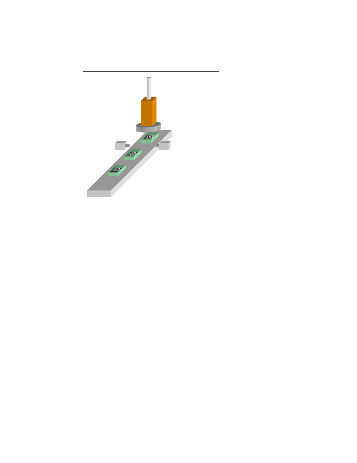
1.3 Processing Setup
Object with
DMC
Sensor head with
ring flash
Light barrier
Triggering
The objects with the data matrix code are fed past the sensor head with a suitable
conveyor.
They must be located fully within the sensor field of view when being read.
In the training mode, the character content of the code is saved.
In the evaluation mode, the current code is read and, if required, compared with the
saved content of the trained code. Depending on the results of the read operation,
the digital output signals are set: READ (code was localized and decoded),
MATCH (code matches the learned code), N_OK (code was not legible).
The result of the read operation is output via the RS-232 interface or via
PROFIBUS. It is also possible to filter the read character string and to append
additional characters at the start or end.
To read the data matrix code, you must make sure that the code is completely
within in the sensor field of view and clearly visible.
The data matrix code is captured at the trigger time. In this case, you generate an
exact trigger signal at the trigger time, for example with a laser light barrier.
You can check your settings with the setup software of the VS 130.
Vision Sensor VS 130
1-4 A5E00199459-01
1.4 Important Requirements for Installation
The following requirements must be met:
• The code must be clearly visible:
- There should be as few reflections is possible in the code field.
- The code field should be uniformly illuminated without shadows.
- All parts of the code should be sharply printed.
• The sensor can be up to 45° from the vertical.
• The distance between the code and the image edge should be at least two dot
widths.
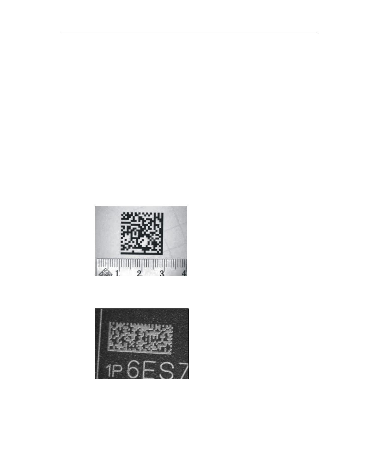
1.5 Applications
Below, you will see several examples of data matrix codes:
• Printed code
Product Overview
• Lasered code (plastic surface)
Vision Sensor VS 130
A5E00199459-01
1-5
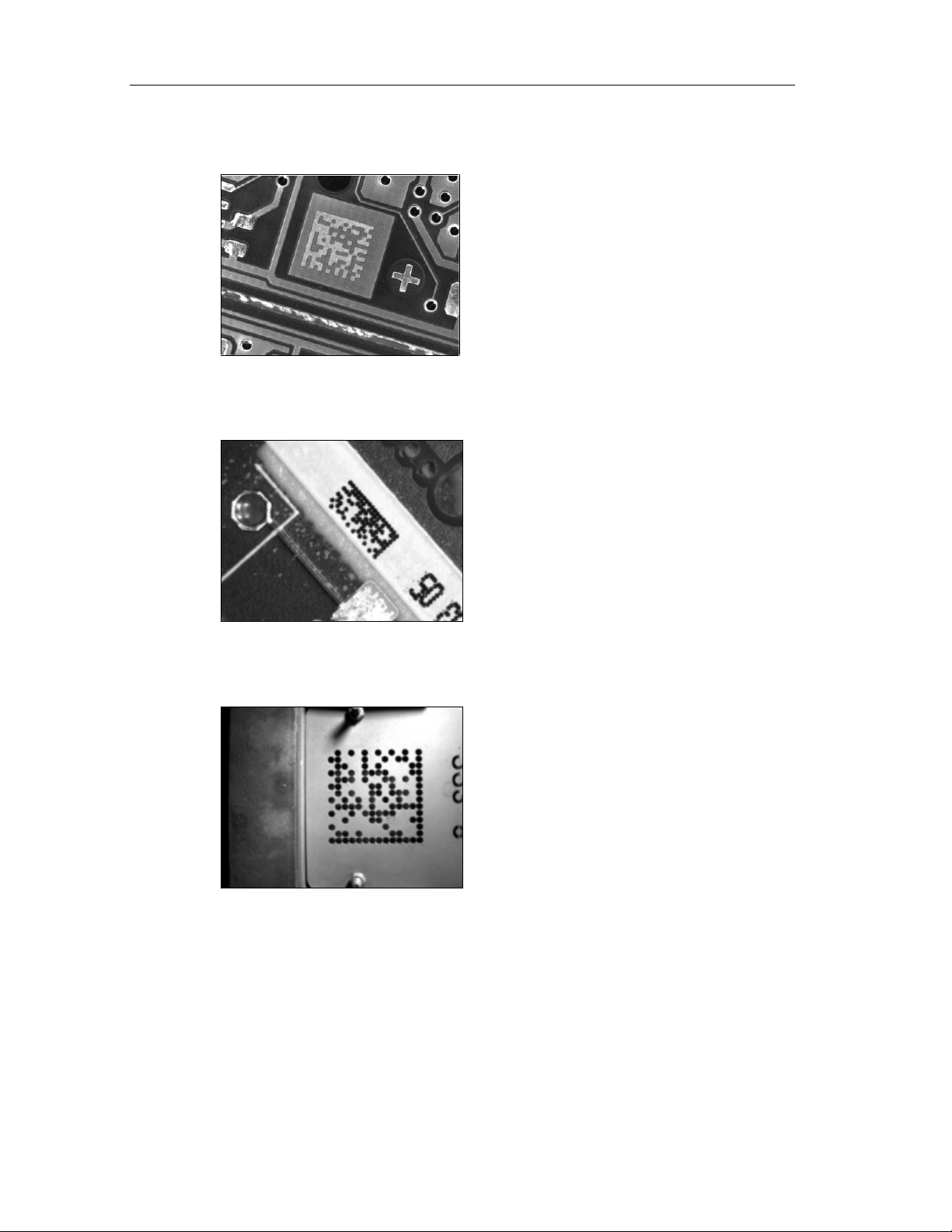
Product Overview
• Lasered code (PCB)
• Code created with inkjet printer
• Punched code
Vision Sensor VS 130
1-6 A5E00199459-01
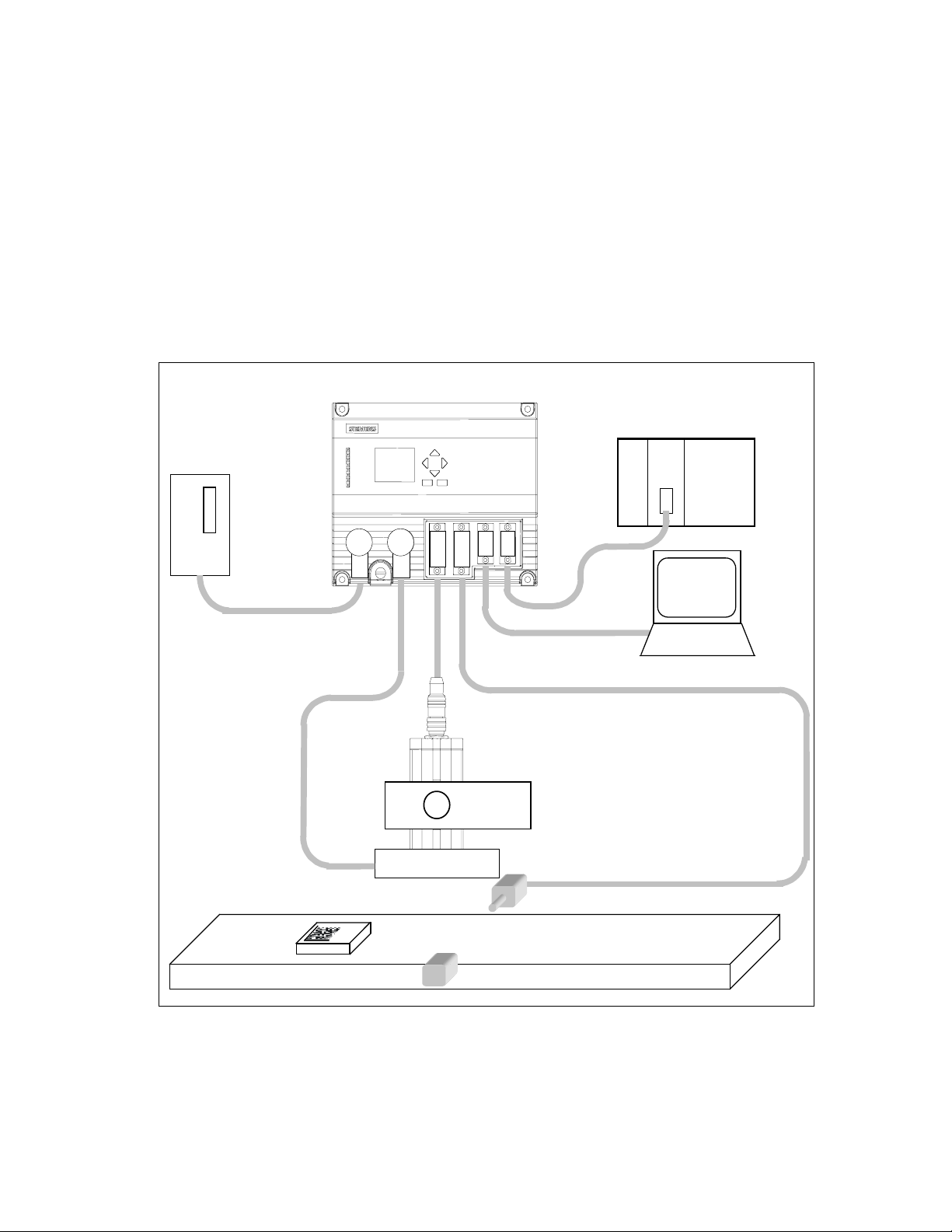
2 System Integration
2.1 Configuration
Processing unit
Programmable controller
Power
supply
PS CPU
PROFIBUS DP
PG / PC
Sensor head
Mounting
mechanism
Ring flash
Light barr ier
Object
with DMC
Vision Sensor SIMATIC VS 130
A5E00199459-01
Conveyor
2-1
System Integration
2.2 Application Examples
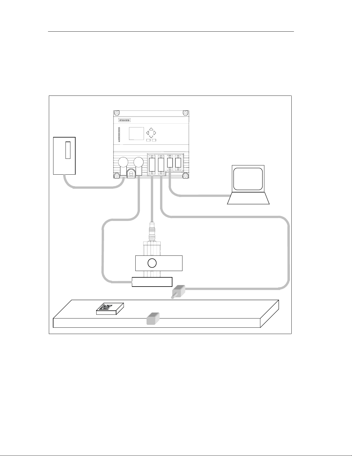
2.2.1 Reading Codes in Stand-alone Mode
Processing unit
Power supply
PG / PC
Sensor head
Mounting
mechanism
Ring flash
Light barrier
Object
with DMC
Conveyor
There is no connection to PROFIBUS.
VS 130 reads the codes and outputs them on a PG/PC connected via the RS-232
interface. It is also possible to filter the read character string and to append
additional characters at the start or end (see section 5.3.4).
Vision Sensor VS 130
2-2 A5E00199459-01
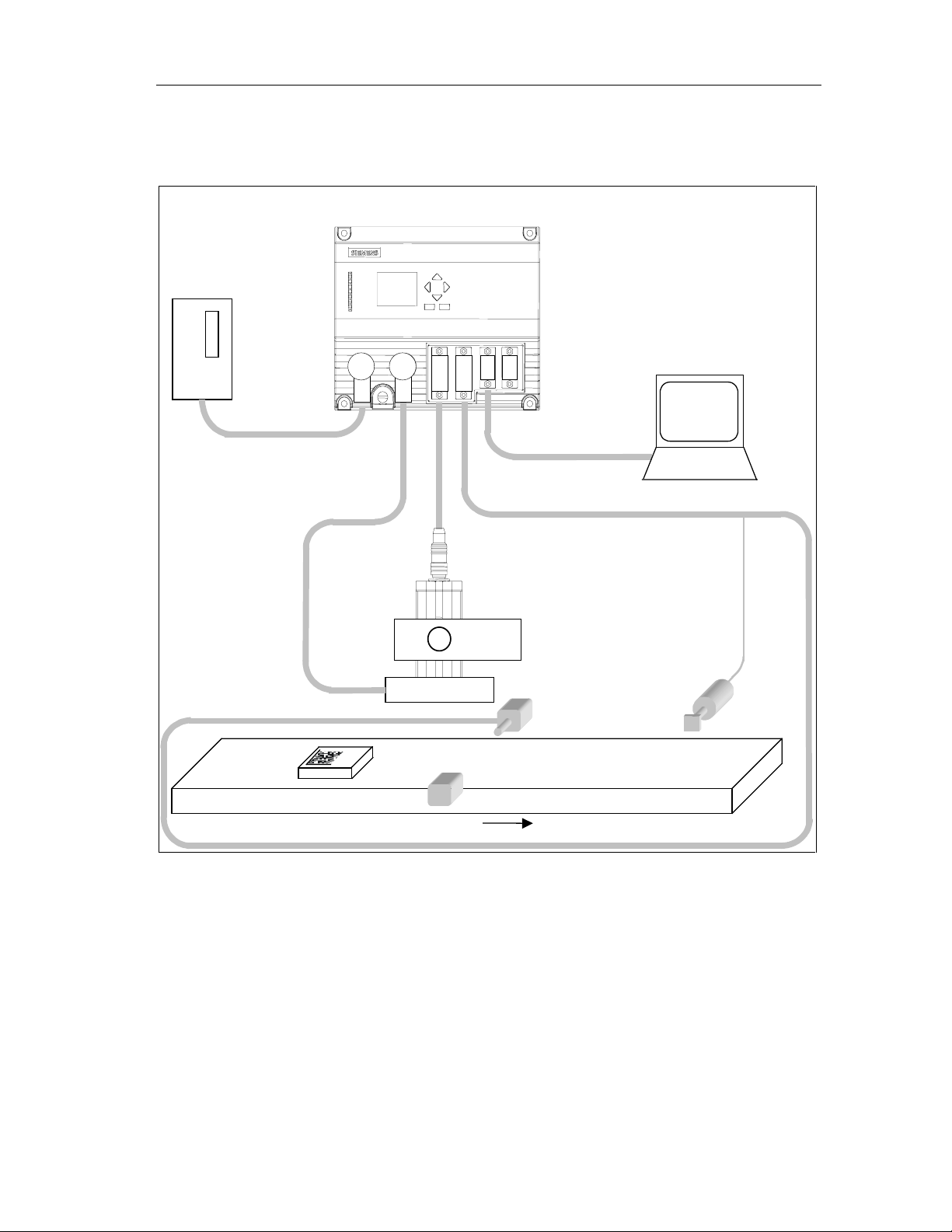
2.2.2 Reading and Comparing Codes in Standalone Mode
Processing unit
Power supply
System Integration
PG / PC
N_OK
Ejector
Object
with DMC
Sensor head
Mounting
mechanism
Ring flash
Light barr ier
Conveyor
Direction of travel
There is no connection to PROFIBUS.
VS 130 reads the codes and compares either the entire code or part of the code
with a user-defined string. If it was not possible to read code (the output signal
N_OK is set), an ejector removes the object from the conveyor.
Vision Sensor VS 130
A5E00199459-01
2-3
System Integration
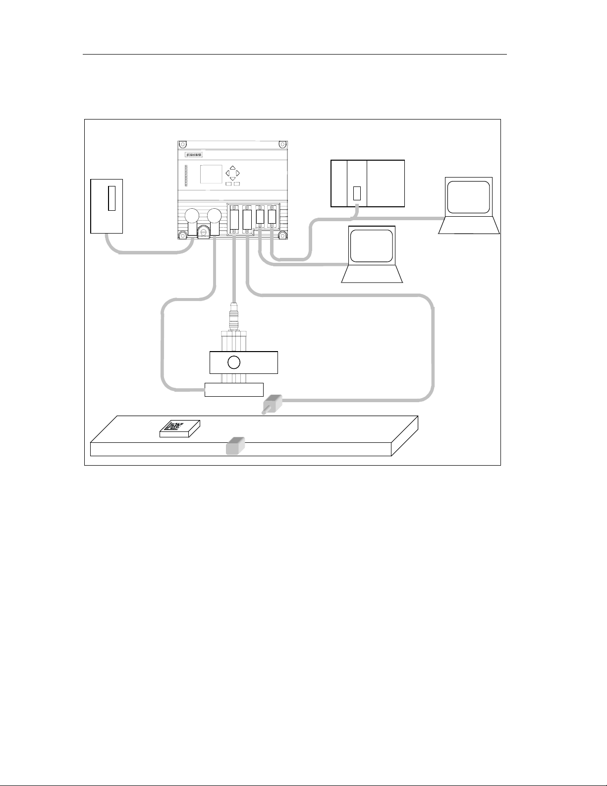
2.2.3 Reading Codes in a PROFIBUS Environment
Processing unit
Programmable controller
Power supply
Object
with DMC
Sensor hea d
Mounting
mechanism
Ring flash
PROFIBUS DP
Light barrier
PS CPU
Conveyor
PG / PC
for display
PG / PC
for setup software
A PG/PC intended solely for setup is connected via the RS-232 interface. Via
PROFIBUS, there is a connection to a PLC and to another PG/PC.
The VS 130 is controlled via PROFIBUS by the PLC and the codes output on this
PG/PC once again via PROFIBUS. In this situation, it is, of course, also possible to
filter the read character string and to append additional characters at the start or
end (see Section 5.3.4).
Vision Sensor VS 130
2-4 A5E00199459-01
System Integration
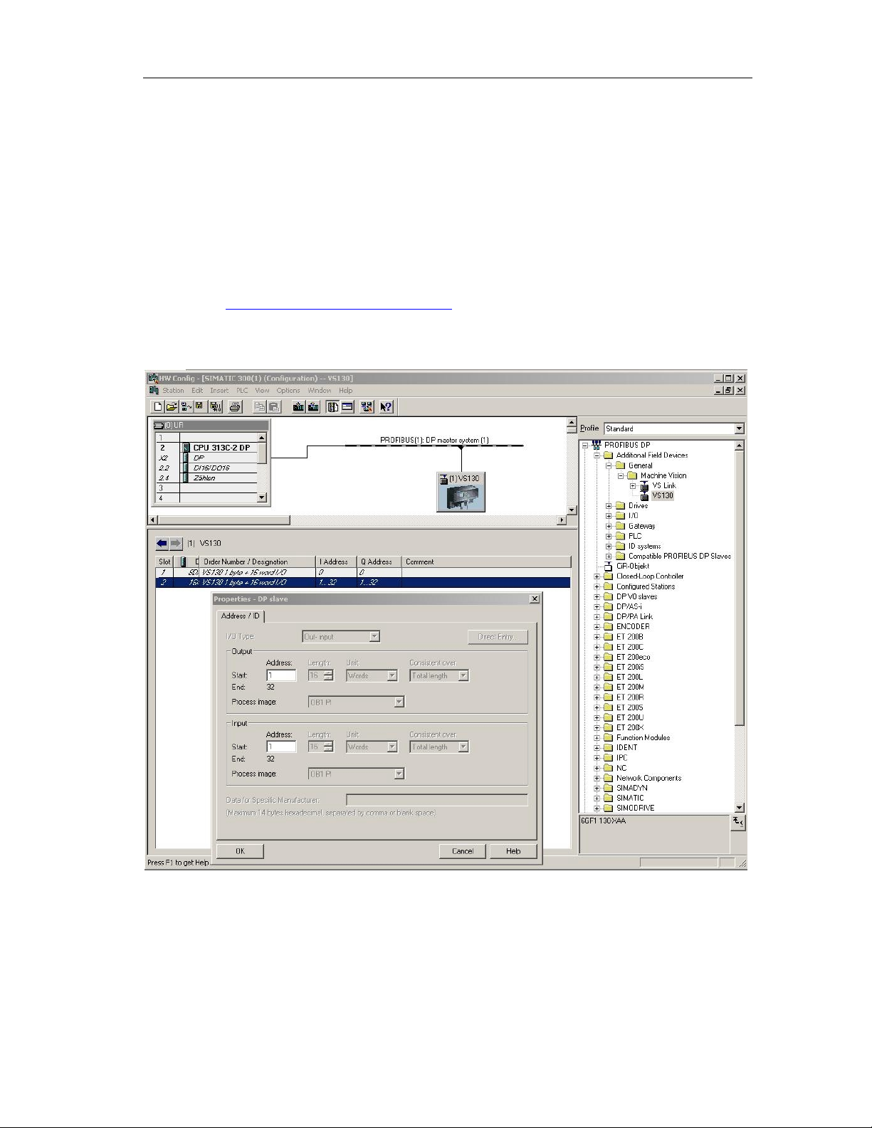
2.3 Including the Vision Sensor VS 130 in HW Config
The supplied device master data file SIEM8100.GSD contains the PROFIBUS
properties of the VS 130 DP standard slave. If you are using a STEP 7 version
earlier than V5.2 SP1, the Vision Sensor VS 130 is not yet in the modules catalog
in HW Config. In this case, you must add it to the catalog with Options > Install
New GSD... . Remember that the corresponding bitmap file VS1X0__N.DIB must
be in the same folder as the GSD file.
You can also download both files from the Internet at
http://www.ad.siemens.de/csi_e/gsd.
The Vision Sensor VS 130 then appears in the modules catalog under PROFIBUS
DP \ Additional Field Devices \ General \ Machine Vision (see screenshot below).
Vision Sensor VS 130
A5E00199459-01
2-5

System Integration
In the configuration example above, the control byte of the VS 130 was set to
output address 0 and the status byte of the VS 130 was set to input address 0 of
the CPU (DP master, slot 1). If these addresses are in the process image of OB1
(process image partition "OB1 PI"), you can work here in OB1 with process image
access (for example "A I0.6" or "S Q0.1"). If this is not the case, you must work
with direct I/O access (for example "L PIB 0").
In the configuration example above, the start of the 16 word long consistent
communication area of the Vision Sensor VS 130 was set to input address 1 and
output address 1 (slot 2). If these addresses are in the process image of OB1
(process image partition "OB1 PI"), you can work in OB1 with process image
access (for example "L IW 2", "T QB 1") without violating the consistency. If, on
the other hand, these addresses are not in the process image of OB1, you must
access the communication area of the VS 130 using SFCs 14 "DPRD_DAT" and
15 "DPWR_DAT" to ensure consistency.
The Vision Sensor VS 130 detects the transmission rate on PROFIBUS
automatically. Even if the transmission rate has changed, this is detected
automatically. The following values possible:
• 9.6 kbps
• 19.2 kbps
• 45.45 kbps
• 93.75 kbps
• 187.5 kbps
• 500 kbps
• 1.5 Mbps
• 3 Mbps
• 6 Mbps
• 12 Mbps
The PROFIBUS address of the VS 130 is set in the Settings > Ports > DP Addr.
menu of the processing unit. Possible values are 1, ... 125.
Changing the PROFIBUS address via PROFIBUS is not supported.
If you assign parameter values to the Vision Sensor VS 130 via PROFIBUS, you
can only set its default values (all zero). If you enter values other than zero here, a
slave diagnostic message is generated ("Invalid DP parameters"). If you are using
an S7-CPU as the DP master, a diagnostic interrupt is triggered (No OB82 start,
because CPU is in STOP): "Faulty module" is entered in the diagnostic buffer and
the "SF" LED is lit.
If problems occur entering the device in HW Config, refer to Chapter 7.
Vision Sensor VS 130
2-6 A5E00199459-01

3 Installation
3.1 Installing Components
Steps in Installation
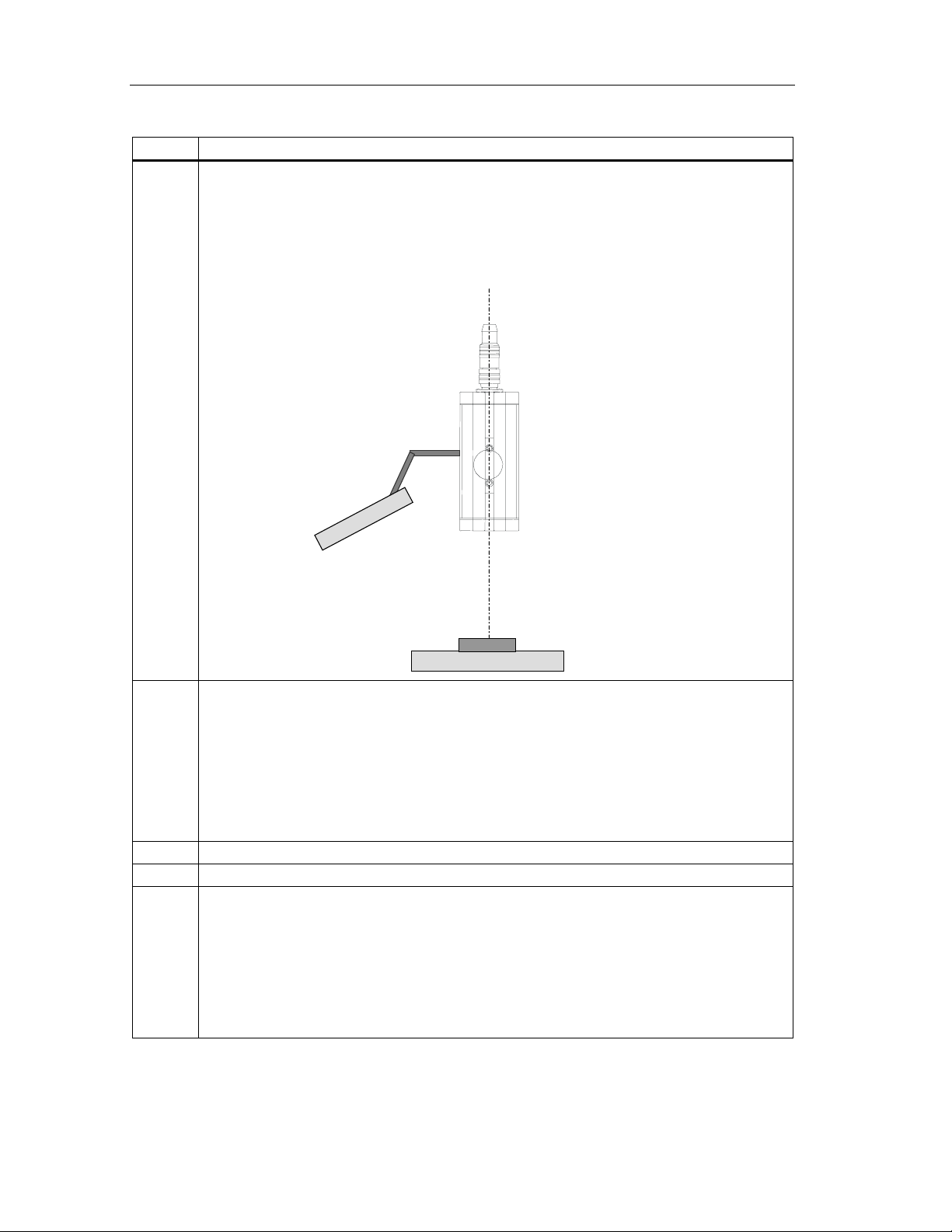
Step Activity
1a Arrange the sensor head so that reflections are kept to a minimum. The angle of its central
axis is typically 15° from vertical (angle α) (permitted angles: 0 ≤ α ≤ 45° ).
Sensor he ad
Vision Sensor SIMATIC VS 130
A5E00199459-01
Ring flash
Object with DMC
Conveyor
3-1
Installation
Step Activity
1b If there is still too much reflection at an angle of 15 °, select an arrangement in which the
sensor head and the ring flash are not concentric.
Note: The mechanism for mounting the ring flash is not supplied with the product.
If the ring flash does not need your requirements, please contact your sales partner who will
be able to recommend other suppliers of lighting for the VS 130.
Mounting
mechanism
Sensor head
Ring flash
Object with DMC
Conveyor
1c Regardless of the arrangement you select, make sure that you maintain the following
clearances (these clearances depend on the type of sensor head) between the end of the
sensor head and the data matrix code you are reading:
• 6GF2 002 8DA: 110 mm clearance
• 6GF2 002 8EA: 85 mm clearance
Caution:
If the code area is relatively large and the sensor is placed close to the code area at a large
angle, the image may be distorted and thus the clarity will be reduced.
2 Install the processing unit so that it is easily accessible for the operator.
3 Install the external triggering unit, for example a light barrier.
4 Start the setup software on the PG/PC, and switch the processing unit to the Adjust mode.
You then see an image as seen by the sensor head.
• Check the trigger signal. Activate the "Triggered only" check box in the "Options" group.
Check whether VS 130 can read the codes with the sensor head in its current position
with the ring flash by activating the "Read" check box in the "Options" group (see Manual,
Section A.7). If necessary, correct the trigger point and/or position of the sensor head.
• Select suitable values for the shutter speed and brightness. The image should not be too
bright.
Vision Sensor VS 130
3-2 A5E00199459-01
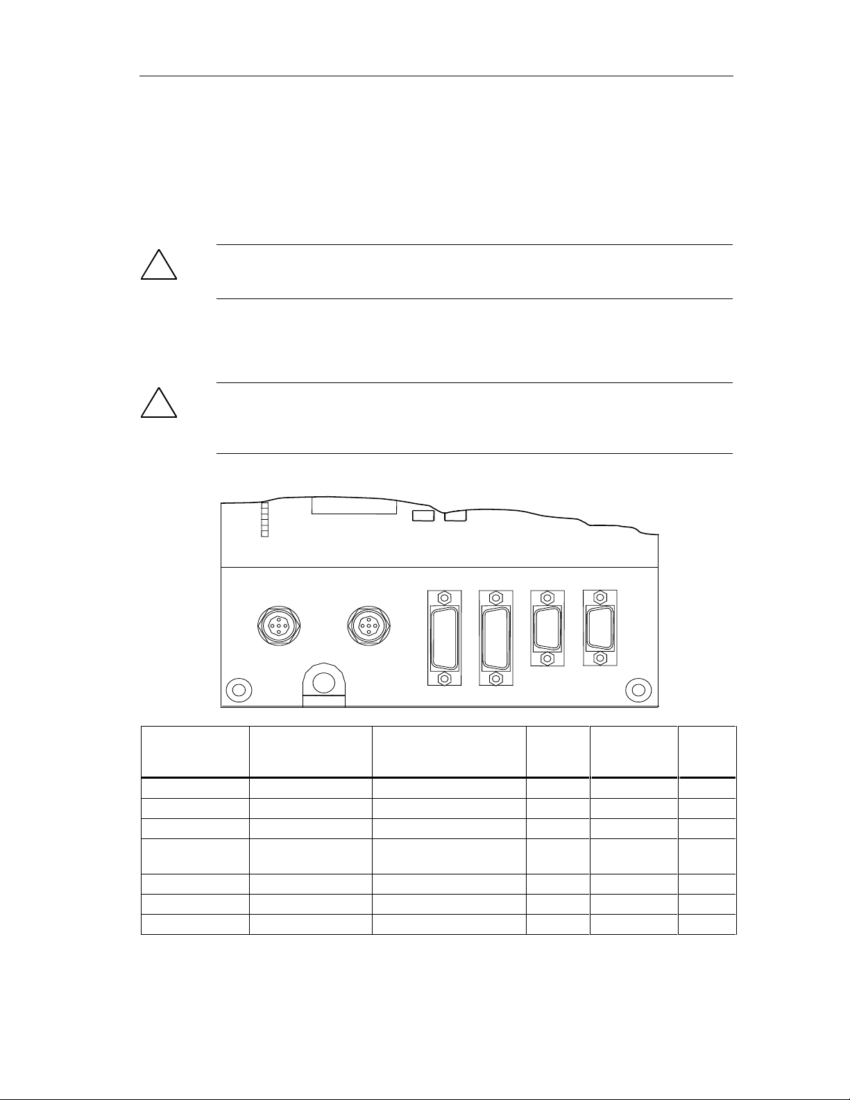
3.2 Wiring Components
Connect the processing unit with the other components using the connectors on
the front panel. The pinning of the connectors is described in Appendix A.5.
Installation
!
Caution!
Do not connect or disconnect cables when the power supply is on.
Apart from the RS-232 cable (6ES7 901-1BF00-0XA0) all the cables are supplied
(see Appendix A.1).
!
Warning
Grounding the VS 130 cancels the ungrounded installation of the power unit used
to operate the VS 130.
LAMPIN DC 24V
SENSOR
DI/DO
RS232
DP
Connector Connector Label Type Number
of
pins
Functional earth - Screw terminal - - Power supply IN DC 24 V Circular connector M12 4 0.56 mm
Lighting unit LAMP Circular connector M12 4 0.23 mm
Sensor head
(shielded cable)
I/O DI/DO Sub D 15 0.14 mm
RS-232 RS-232 Sub D 9 - Pin
PROFIBUS DP PROFIBUS DP Sub D 9 - Socket
* The supplied ferrite ring must be fixed to the sensor cable (approx. 50 mm from connector to
processing unit).
Vision Sensor VS 130
A5E00199459-01
SENSOR HD Sub D * 26 0.09 mm
Cable Cross
Section
2
2
2
2
Type
Pin
Socket
Socket
Socket
3-3

Installation
Step Activity
1 Read the guidelines on preventing electrical interference (see Section 3.3).
2 Connect the processing unit to the sensor head and the lighting unit with the cables.
3 If you do not want to process the result bits READ, MATCH, N_OK via PROFIBUS DP: Connect
the READ, MATCH, N_OK digital outputs as described in Section 6.1.1.
4 Connect the trigger signal via the TRG digital input.
5 If you intend to control the SIMATIC VS 130 with a PLC, connect the other digital inputs and
outputs as described in Section 6.1.1
6 Connect functional ground of the processing unit to chassis ground
(diameter of the ring: M5, cable cross section 1.5 mm
7 Connect the processing unit to the 24 V power supply (2 A).
8 Connect the PC / PG via the RS-232 interface. The PC / PG is required only for setting up the
sensor.
Optional (not supplied with the package):
RS-232 cable 5 m long, connectors prefitted at SIMATIC VS 130 end and PLC/PC end
(pinning, see Appendix A.5).
2
).
Note
The DC load power supply must meet the following requirements:
Only low voltage less than or equal to 24 V DC safely isolated from the power
supply network must be used for the load current supply. Safe isolation can be
implemented, for example, by adhering to the specifications in
VDE 0100-410 / HD 384-4-41 S2 / IEC 60364-4-41
(functional low voltage with safe isolation) or
VDE 0805 / EN 60950 / IEC 60950
(as safety extra-low voltage SELV) or VDE 0106 Part 101.
Note
The supply chassis of the I/O and CPU must be connected to the supply chassis of
the processing unit.
Vision Sensor VS 130
3-4 A5E00199459-01

3.3 Guidelines on Preventing Electrical Interference
To avoid interference, you must shield your system. Low-frequency (LF) and highfrequency (HF) interference signals can result in an incorrect response if the
system is badly grounded or not shielded.
Interference signals can be caused, for example, by switching relays or contactors
(high rates of change in current or voltage, HF interference signals) or by different
ground potentials between two parts of a system (LF interference signals).
Using/Laying Interference-Proof Cable
• The cable to the sensor head and the RS-232 cable must be shielded.
The standard cables supplied by Siemens meet these requirements.
• All plug-in connections must be secured by screws or a locking mechanism.
• Signal lines must not run parallel to power cables. A separate cable channel
must be used with a minimum clearance of 50 cm from power cables.
Installation
Note
For more detailed information, refer to the installation manual SIMATIC S7-300
Programmable Controller, Hardware and Installation in the section on "Wiring".
3.4 Guidelines for Use of PROFIBUS DP
If you are using PROFIBUS DP (to control the device and/or to transfer the results)
the installation and configuration guidelines must be kept to. You will find this
information in the installation manual SIMATIC S7-300 Programmable Controller,
Hardware and Installation.
Vision Sensor VS 130
A5E00199459-01
3-5

Installation
Vision Sensor VS 130
3-6 A5E00199459-01

4 Putting into Operation
You can operate the Vision Sensor SIMATIC VS 130 interactively or con trolled by
signals:
• In this chapter, you will learn about interacti ve oper ati on us ing the operator
control and display field of the processing unit.
• Chapter 6 explains the options open to you with signal-controlled operation.
4.1 Turning on the Device
Turn on the power on the processing unit. The text "SIMATIC VS 130 V ..." and the
current firmware version appear on the display.
The VS 130 then runs through the following tests:
• Test of the sensor head
• Check of the saved settings and code data
• If applicable, test of whether data can be exchanged on PROFIBUS (This test
is performed if you have selected "DP" in one or more of the following menus
on the processing unit: Settings > Ports > Result, Settings > Ports > Trigger,
Settings > Ports > Control).
If there are no errors in the self test, either the RUN menu or the STOP menu is
displayed depending on the status when you last shut down.
"RUN" menu: "STOP" menu level:
> C 01 RUN v
=SERIES 7
OK:Menu
Vision Sensor SIMATIC VS 130
A5E00199459-01
> Train
RUN
Adjust
↓ OK
4-1
 Loading...