

Page 1

SIMATIC Sensors Image processing systems Vision Sensor SIMATIC VS120
DOCUMENTATION
Operating Instructions Edition 02/2006
Image Processing Systems
SIMATIC VS120
simatic sensors
DOCUMENTATION
Page 2

Page 3

SIMATIC Sensors
Image processing systems
Vision Sensor SIMATIC VS120
Operating Instructions
Introduction
Safety instructions
Description
Image processing
Network and system
integration
Installation
Connecting
1
2
3
4
5
6
7
Commissioning
Operation
Process interfacing over an
automation system (PLC,
PC)
Alarm, error and system
messages
Technical data
Dimension drawings
Scope of
delivery/Spares/Accessories
8
9
10
11
12
13
14
Edition 02/2006
A5E00757507-01
Service & Support
Directives and declarations
15
16
Page 4

Safety Guidelines
This manual contains notices you have to observe in order to ensure your personal safety, as well as to prevent
damage to property. The notices referring to your personal safety are highlighted in the manual by a safety alert
symbol, notices referring only to property damage have no safety alert symbol. These notices shown below are
graded according to the degree of danger.
Danger
indicates that death or severe personal injury will result if proper precautions are not taken.
Warning
indicates that death or severe personal injury may result if proper precautions are not taken.
Caution
with a safety alert symbol, indicates that minor personal injury can result if proper precautions are not taken.
Caution
without a safety alert symbol, indicates that property damage can result if proper precautions are not taken.
Notice
indicates that an unintended result or situation can occur if the corresponding information is not taken into
account.
If more than one degree of danger is present, the warning notice representing the highest degree of danger will
be used. A notice warning of injury to persons with a safety alert symbol may also include a warning relating to
property damage.
Qualified Personnel
The device/system may only be set up and used in conjunction with this documentation. Commissioning and
operation of a device/system may only be performed by qualified personnel. Within the context of the safety notes
in this documentation qualified persons are defined as persons who are authorized to commission, ground and
label devices, systems and circuits in accordance with established safety practices and standards.
Prescribed Usage
Note the following:
Warning
This device may only be used for the applications described in the catalog or the technical description and only in
connection with devices or components from other manufacturers which have been approved or recommended
by Siemens. Correct, reliable operation of the product requires proper transport, storage, positioning and
assembly as well as careful operation and maintenance.
Trademarks
All names identified by ® are registered trademarks of the Siemens AG. The remaining trademarks in this
publication may be trademarks whose use by third parties for their own purposes could violate the rights of the
owner.
Disclaimer of Liability
We have reviewed the contents of this publication to ensure consistency with the hardware and software
described. Since variance cannot be precluded entirely, we cannot guarantee full consistency. However, the
information in this publication is reviewed regularly and any necessary corrections are included in subsequent
editions.
Siemens AG
Automation and Drives
Postfach 48 48
90437 NÜRNBERG
GERMANY
Order No.: A5E00757507-01
Edition 02/2006
Copyright © Siemens AG 2006.
Technical data subject to change
Page 5

Table of contents
1 Introduction............................................................................................................................................. 1-1
2 Safety instructions .................................................................................................................................. 2-1
3 Description.............................................................................................................................................. 3-1
3.1 Product description .................................................................................................................... 3-1
3.2 Performance features ................................................................................................................ 3-2
3.3 Function ..................................................................................................................................... 3-3
3.4 System components .................................................................................................................. 3-4
3.5 System requirements................................................................................................................. 3-5
3.6 Design of the SIMATIC VS120 processing unit......................................................................... 3-6
3.7 Design of the sensor head with LED ring flash.......................................................................... 3-8
4 Image processing ................................................................................................................................... 4-1
4.1 General information ................................................................................................................... 4-1
4.2 Shutter Speed and Brightness................................................................................................... 4-2
4.2.1 Different exposures and brightnesses ....................................................................................... 4-2
4.2.2 Disturbing contours caused by shine......................................................................................... 4-3
4.3 Generating models and detecting orientation............................................................................ 4-5
4.3.1 Setting for the Precision parameter ........................................................................................... 4-5
4.3.2 Measures for optimizing object recognition ...............................................................................4-6
4.4 Quality of the measured values ................................................................................................. 4-7
4.5 Geometric distortion................................................................................................................... 4-8
4.6 Main ROI and sub-ROI .............................................................................................................. 4-8
4.6.1 Example: Main ROI and 3 sub-ROIs .........................................................................................4-9
4.6.2 Example of the influence of sub-ROIs on the quality value..................................................... 4-10
4.7 Job parameter.......................................................................................................................... 4-13
4.8 Search parameter .................................................................................................................... 4-16
4.9 Model type parameter .............................................................................................................. 4-17
4.10 Model sets................................................................................................................................ 4-19
5 Network and system integration...............................
...............................................................................
5-1
5.1 Overview .................................................................................................................................... 5-1
5.2 System configuration over digital I/O ......................................................................................... 5-2
5.3 PROFIBUS DP system configuration ........................................................................................ 5-3
5.4 PROFINET IO system configuration.......................................................................................... 5-4
5.5 System configuration with Ethernet or RS-232 over Com server.............................................. 5-5
Vision Sensor SIMATIC VS120
Operating Instructions, Edition 02/2006, A5E00757507-01
iii
Page 6

Table of contents
6 Installation .............................................................................................................................................. 6-1
6.1 Installing the SIMATIC VS120 processing unit .......................................................................... 6-1
6.2 Installing the sensor head with LED ring flash........................................................................... 6-1
7 Connecting ............................................................................................................................................. 7-1
7.1 Guidelines on installation and avoiding electrical interference .................................................. 7-1
7.2 Guidelines on installation when using PROFIBUS DP or PROFINET IO.................................. 7-1
7.3 Connecting components ............................................................................................................ 7-2
8 Commissioning ....................................................................................................................................... 8-1
8.1 Prerequisites .............................................................................................................................. 8-1
8.2 Overview of the steps in commissioning.................................................................................... 8-2
8.3 Turn on the VS120 processing unit............................................................................................ 8-3
8.4 Establish an Ethernet connection between the processing unit and PG / PC........................... 8-5
8.4.1 Select the connection variant..................................................................................................... 8-5
8.4.1.1 Connection variants ................................................................................................................... 8-5
8.4.1.2 Operating the VS120 processing unit as a DHCP server.......................................................... 8-6
8.4.1.3 Connecting the VS120 processing unit manually ...................................................................... 8-7
8.4.1.4 Integrating the VS120 processing unit as a DHCP client in a network...................................... 8-9
8.4.1.5 Integrating the VS120 processing unit as a device in a PROFINET IO network..................... 8-10
8.4.2 Check whether a proxy server is being used ........................................................................... 8-12
8.4.3 Change the proxy configuration of your Internet Explorer ....................................................... 8-13
8.4.4 Check the connection............................................................................................................... 8-14
8.5 Start setup support over the Internet Explorer......................................................................... 8-15
8.6 Adjust the sensor head using setup support............................................................................ 8-17
9 Operation................................................................................................................................................ 9-1
9.1 Overview .................................................................................................................................... 9-1
9.2 Working with the processing unit ............................................................................................... 9-1
9.2.1 Introduction ................................................................................................................................ 9-1
9.2.2 Adjust ......................................................................................................................................... 9-2
9.2.3 Connect......................................................................................................................................
9-2
9.2.4 RUN............................................................................................................................................ 9-9
9.2.5 Options..................................................................................................................................... 9-15
9.2.6 Maintain.................................................................................................................................... 9-18
9.3 Working with setup support...................................................................................................... 9-19
9.3.1 Introduction .............................................................................................................................. 9-19
9.3.2 Adjust Sensor........................................................................................................................... 9-24
9.3.3 Connections ............................................................................................................................. 9-25
9.3.4 Train ......................................................................................................................................... 9-27
9.3.5 Processing................................................................................................................................ 9-33
9.3.6 Options..................................................................................................................................... 9-37
9.3.7 Information ............................................................................................................................... 9-43
9.3.8 Maintain.................................................................................................................................... 9-49
9.3.9 Stop.......................................................................................................................................... 9-51
10 Process interfacing over an automation system (PLC, PC) .................................................................. 10-1
10.1 Integrating the PROFIBUS DP slave SIMATIC VS120 in HW Config ..................................... 10-1
10.2 Integrating the PROFINET IO device SIMATIC VS120 in HW Config..................................... 10-4
10.3 Control over the "DI/DO" I/O interface ..................................................................................... 10-7
Vision Sensor SIMATIC VS120
iv Operating Instructions, Edition 02/2006, A5E00757507-01
Page 7

Table of contents
10.4 Control over PROFIBUS DP and PROFINET IO................................................................... 10-10
10.4.1 Principle of data transfer over PROFIBUS DP and PROFINET IO ....................................... 10-10
10.4.2 Assignments for PROFIBUS DP / PROFINET IO-relevant interfaces for the
processing unit....................................................................................................................... 10-11
10.4.2.1 Control byte............................................................................................................................ 10-11
10.4.2.2 Status byte ............................................................................................................................. 10-12
10.4.2.3 User data interface "Send" VS120 processing unit >>> automation system......................... 10-12
10.4.2.4 User data interface "Receive" automation system >>> VS120 processing unit.................... 10-14
10.4.3 Programming data fragmentation .......................................................................................... 10-14
10.5 Function block FB1 ................................................................................................................ 10-16
10.5.1 Job ......................................................................................................................................... 10-16
10.5.2 Parameter .............................................................................................................................. 10-17
10.5.3 Operator control ..................................................................................................................... 10-19
10.5.4 Error information .................................................................................................................... 10-20
10.6 Sample programs................................................................................................................... 10-21
10.6.1 Example 1: Program for interfacing the SIMATIC VS120 processing unit with a
SIMATIC controller using FB1 ............................................................................................... 10-21
10.6.2 Example 2: Program for archiving diagnostic information on a PC/PG................................. 10-23
11 Alarm, error and system messages ...................................................................................................... 11-1
11.1 Overview .................................................................................................................................. 11-1
11.2 Error messages and error handling ......................................................................................... 11-1
11.3 Diagnostics based on the "BF" LED ...................................................................................... 11-10
11.4 Slave diagnostics or /O device diagnostics ........................................................................... 11-11
12 Technical data ...................................................................................................................................... 12-1
12.1 General technical specifications .............................................................................................. 12-1
12.2 Technical specifications of SIMATIC VS120 ........................................................................... 12-5
12.3 Port assignment of the processing unit.................................................................................... 12-8
13 Dimension drawings ............................................................................................................................. 13-1
13.1 SIMATIC VS120 processing unit ............................................................................................. 13-1
13.2 SIMATIC VS120 sensor head.................................................................................................. 13-2
13.3 SIMATIC VS120 lighting unit ...............................
....................................................................
13-3
14 Scope of delivery/Spares/Accessories.................................................................................................. 14-1
14.1 Components............................................................................................................................. 14-1
14.2 Full packages ........................................................................................................................... 14-2
14.3 Accessories.............................................................................................................................. 14-4
14.4 C-mount lens and inspection window size............................................................................... 14-5
15 Service & Support................................................................................................................................. 15-1
15.1 A&D Mall / Interactive Catalog (CA01) .................................................................................... 15-1
15.2 Service and support ................................................................................................................. 15-1
16 Directives and declarations................................................................................................................... 16-1
Glossary ..................................................................................................................................... Glossary-1
Index................................................................................................................................................ Index-1
Vision Sensor SIMATIC VS120
Operating Instructions, Edition 02/2006, A5E00757507-01
v
Page 8

Table of contents
Vision Sensor SIMATIC VS120
vi Operating Instructions, Edition 02/2006, A5E00757507-01
Page 9

Introduction
Purpose of the manual
This manual contains all the information you require to install, commission and work with the
SIMATIC VS120 Vision Sensor System.
It is intended both for persons configuring and installing automated plants with image
processing systems and for service and maintenance technicians.
Scope of this manual
The manual is valid for all supplied versions of the SIMATIC VS120 Vision Sensor system
and the processing unit with order number (MLFB) 6GF1 018-2AA10.
1
Vision Sensor SIMATIC VS120
Operating Instructions, Edition 02/2006, A5E00757507-01
1-1
Page 10

Introduction
Vision Sensor SIMATIC VS120
1-2 Operating Instructions, Edition 02/2006, A5E00757507-01
Page 11

Safety instructions
Caution
Please observe the safety instructions on the back of the cover sheet of this documentation.
You should not make any expansions to your device unless you have read the relevant
safety instructions.
This device meets the relevant safety requirements in compliance with IEC, VDE, and EN. If
you have questions about the validity of the installation in the planned environment, please
contact your service representative.
Repairs
Only authorized personnel are permitted to repair the device.
Warning
Unauthorized opening of and improper repairs to the device may result in substantial
damage to equipment or risk of personal injury to the user.
2
System expansion
Only install system expansions intended for this device. If you install other upgrades, you
may damage the system or violate the safety requirements and regulations for radio
frequency interference suppression. Contact your technical support team or where you
purchased your device to find out which system expansion devices may safely be installed.
Caution
If you install or exchange system expansions and damage your device, the warranty
becomes void.
Vision Sensor SIMATIC VS120
Operating Instructions, Edition 02/2006, A5E00757507-01
2-1
Page 12

Safety instructions
Vision Sensor SIMATIC VS120
2-2 Operating Instructions, Edition 02/2006, A5E00757507-01
Page 13

Description
3.1 3.1 Product description
The SIMATIC VS120 Vision Sensor is used for the optical detection and testing of objects
with lighting from above. The SIMATIC VS120 Vision Sensor checks whether or not the
correct object is being tested, whether or not it is damaged and the position of the object.
The SIMATIC VS120 Vision Sensor returns the following recognition values during object
recognition:
• x coordinate
• y coordinate
• Angle
• Quality rating of the specimen, number of detected parts
This object recognition data is transferred to processing units in automation systems. The
data is processed in the processing units of the automation systems.
The SIMATIC VS120 Vision Sensor is suitable for:
• Recognition of parts in sorting tasks
• Determining the position for Pick & Place applications
3
• Checking the presence and position of objects in production
• Checking position in feed systems, for example with oscillating conveyors, workpiece
holder, conveyor belts, circulating systems, grasper units and robots.
• Quality control of specimens
Vision Sensor SIMATIC VS120
Operating Instructions, Edition 02/2006, A5E00757507-01
3-1
Page 14

Description
3.2 Performance features
3.2 3.2 Performance features
• Overhead lighting head with LED ring flash
• Object recognition with object search and object test
• Commissioning using adjustment support on the PG / PC with installed Internet Explorer
• Up to 20 objects tested per second
• Up to 64 specimens can be stored
• Two digital outputs are available for sorting the specimens: OK, N_OK
• Fully Web-based user interface
• Extensive operator control and monitoring functions even in the processing mode
• Wide-ranging diagnostics and logging functions: Error image memory and event logging
• Firmware update using operator interface of the Web browser
• Control via Digital I/O, PROFIBUS DP and PROFINET IO
• Result output via:
– PROFIBUS DP
– PROFINET IO
– RS-232 port of an RS-232 Ethernet converter
– TCP/IP connection of the PC / PG
Vision Sensor SIMATIC VS120
3-2 Operating Instructions, Edition 02/2006, A5E00757507-01
Page 15

Description
3.3 Function
3.3 3.3 Function
Testing correctness of individual characteristics of the specimen
64 models are available for the recognition of specimens. The SIMATIC VS120 checks
whether or not the individual characteristics of the specimens have the same shape as the in
the trained model.
When specifying the recognition and evaluation areas, avoid shiny surfaces on specimens.
Principle of edge recognition
To recognize image patterns, edges are used. These edges from the images are the
transitions from light to dark or vice versa. A model is created from the sum of the edges
extracted in the image and their arrangement.
Recognition and localization of parts
The SIMATIC VS120 scans specimens and determines the coordinates including the roll
angle and passes them to the control system such as S7, for example, via PROFIBUS DP.
Testing the completeness of a model
The SIMATIC VS120 also checks specimens for completeness. Deviations from the trained
model are detected and the quality values of the evaluation are displayed.
Sorting functions for models and model sets
Depending on the importance of the application, 15 model sets with 64 different models can
be assembled and saved for processing. The models are sorted according to the application
with a controller for processing with the SIMATIC VS120.
Vision Sensor SIMATIC VS120
Operating Instructions, Edition 02/2006, A5E00757507-01
3-3
Page 16
Description
3.4 System components
3.4 3.4 System components
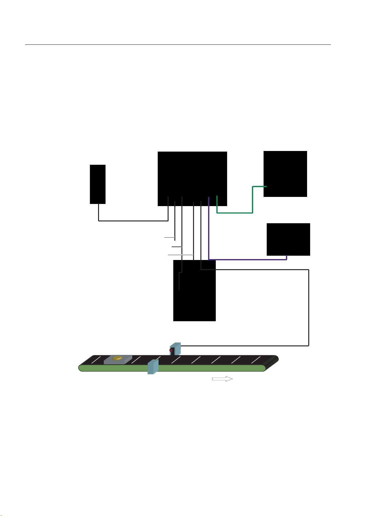
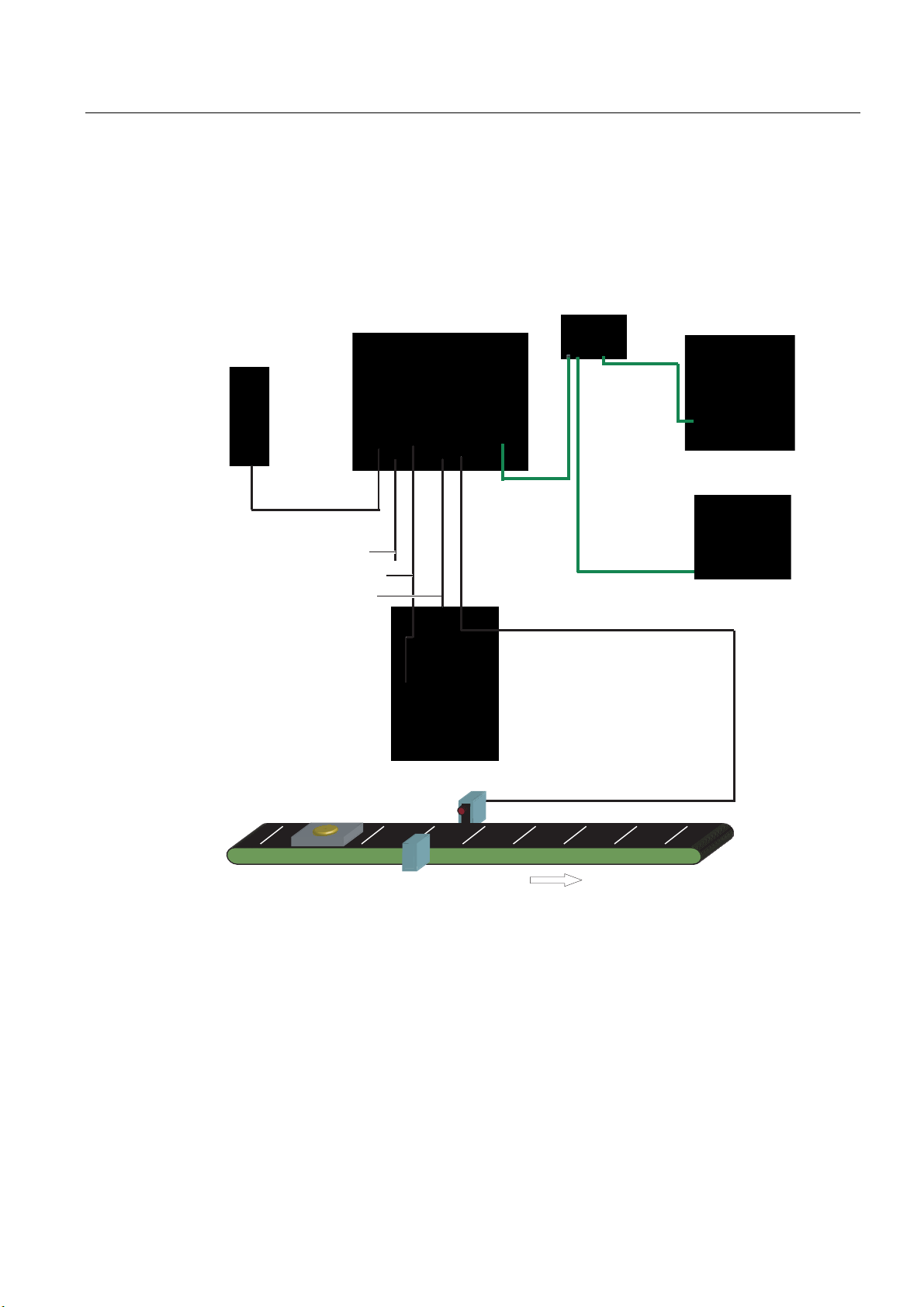
SIMATIC VS120 Vision Sensor full package comprising:
• Sensor
• Processing unit
• Lighting
• Cable
3RZHU
VXSSO\
3RZHUVXSSO\FDEOH
)XQFWLRQDOHDUWKLQJ
/LJKWLQJFDEOH
6HQVRUFDEOH
3URFHVVLQJXQLW
3*3&IRU
DGMXVWPHQWVXSSRUW
5- (WKHUQHW
FDEOH
$XWRPDWLRQV\VWHP
352),%86b'3
','2FDEOH
6HQVRUKHDG
/('ULQJIODVK
2EMHFW
3KRWRHOHFWULFEDUULHU
&RQYH\RUXQLW
&RQYH\RUXQLW
Figure 3-1 Example of a typical system configuration with conveyor system
Vision Sensor SIMATIC VS120
3-4 Operating Instructions, Edition 02/2006, A5E00757507-01
Page 17

Description
3.5 System requirements
3.5 3.5 System requirements
You require the following hardware and software components for the SIMATIC VS120 Vision
Sensor system:
Hardware
• SIMATIC VS120 processing unit
• Sensor head with CCD sensor chip for detection of the object
• LED ring flash for SIMATIC VS with degree of protection IP65 (not included in every full
package), for optimum illumination of the object
• Cables:
– Power supply cable
– Lighting cable
– Sensor cable
– DI / DO cable
• Documentation package
Software
– Operating Instructions (compact)
– Documentation CD
You also require the following:
• 24 V DC, 2 A power supply; (20.4...28.8 V DC, safety extra low voltage, SELV).
• PC / PG with the following configuration:
– At least 500 MHz clock frequency
– Graphics card with at least 65536 colors and a resolution of at least 1024 x 768 pixels
– Ethernet port with up to 100 Mbps (protocol: TCP/IP)
• Crossover RJ-45 Ethernet cable for connecting the processing unit and the PC / PG
• Microsoft Windows XP Professional SP1 operating system with Internet Explorer 6.0 as of
SP1
• Microsoft Java VM or Sun Java VM version J2SE 1.4.2_06 or J2SE 5.0 (you will find
more detailed information on the Internet at the following address
http//:www.java.sun.com/J2SE)
Vision Sensor SIMATIC VS120
Operating Instructions, Edition 02/2006, A5E00757507-01
3-5
Page 18
Description
3.6 Design of the SIMATIC VS120 processing unit
3.6 3.6 Design of the SIMATIC VS120 processing unit
VS120 processing unit (MLFB 6GF1 0182AA10)
Item
Meaning
No.
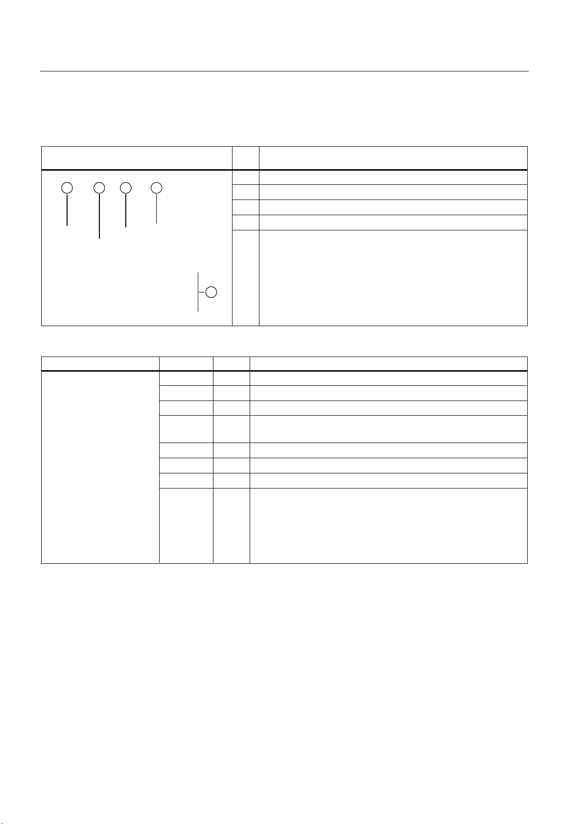
(1) Status LEDs
(2) LCD display
(3) Keypad
(4) Housing consisting of hood and base
(5) Interfaces
Status LEDs LEDs Color Meaning
SF Red General fault
POWER Green Power supply is turned on
TRAINED Green Selected model has been trained
READY Green
OK Green Result good: Model was recognized
- Green N_OK Yellow Result bad: Object was not recognized
BF Red Bus fault on PROFIBUS DP or PROFINET IO
• off = device startup or SIMATIC VS120 in Stop
• on = SIMATIC VS120 in Run
Vision Sensor SIMATIC VS120
3-6 Operating Instructions, Edition 02/2006, A5E00757507-01
Page 19
Description
3.6 Design of the SIMATIC VS120 processing unit
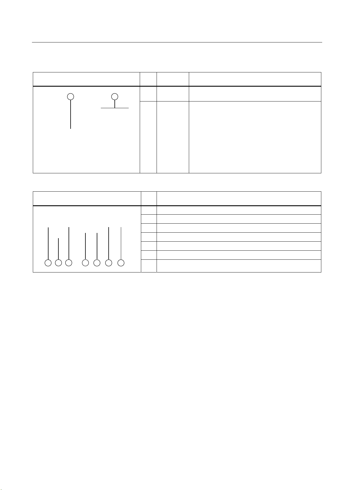
LCD display and keypad Item
Designation Meaning
No.
(1) LCD
display
(2)
Keypad
Displays menu commands (lines 1 to 3) and the keys
that are currently available (line 4)
Navigation from menu to menu and within the menus
Interfaces Item
Meaning
No.
(1) Supply voltage 24 V DC, circular M12 connector
(2) Functional ground with M5 screw-type connector
(3) Lighting unit, circular M12 connector
(4) Sensor head, HD D-sub connector, 26-pin
(5) I/O, D-sub connector, 15-pin
(6) PROFIBUS DP, D-sub connector, 9-pin
(7) Ethernet / PROFINET IO; RJ-45 plug
Vision Sensor SIMATIC VS120
Operating Instructions, Edition 02/2006, A5E00757507-01
3-7
Page 20

Description
3.7 Design of the sensor head with LED ring flash
3.7 3.7 Design of the sensor head with LED ring flash
Sensor head with LED ring flash Item
No.
(1)
(2)
(3)
(4)
Meaning
Circular connector M12
Sensor head
LED ring flash (not supplied with all full packages)
Lens, permanently installed and non-adjustable (fixed focus version)
Vision Sensor SIMATIC VS120
3-8 Operating Instructions, Edition 02/2006, A5E00757507-01
Page 21

Image processing
4.1 4.1 General information
To form patterns that can be recognized, edges (transitions from light to dark or vice versa)
from the image are used. Although the algorithm extracts the edges automatically, the user
must make sure that the lighting is ideal for an image with good contrast; in other words, to
create models for recognition, it is essential to use the lighting correctly to achieve an image
with high contrast.
Note
The installation of suitable lighting often involves more time than all the other activities such
as securing the camera, connecting to the PLC, training, setting the correct triggers etc.
together. With metallic surfaces in particular, it is advisable to ask the advice of a lighting
expert due to the possible shine.
Part of object recognition is the recognition of the position of the object in the image.
The starting point is the midpoint of the image to which all coordinates relate. The top left
has the coordinates (-320; 240) and bottom right (320; -240).
4
If the object is not recognized, the position at the top left is output for x / y. The user should
always query whether or not this is an OK / N_OK evaluation and not rely on the x / y
positions!
Vision Sensor SIMATIC VS120
Operating Instructions, Edition 02/2006, A5E00757507-01
4-1
Page 22

Image processing
4.2 Shutter Speed and Brightness
4.2 4.2 Shutter Speed and Brightness
Correct exposure time (shutter speed) influences the quality of the extracted edges. To
control the exposure time / brightness, you can use the parameters Shutter speed and
Brightness.
The shutter speed / brightness must be set to obtain the optimum contrast. The automatic
exposure control can help to achieve the optimum shutter speed setting.
Below, you will find examples of different shutter speeds and disturbing contours:
4.2.1 Different exposures and brightnesses
Correct exposure
Shutter speed: 3800
Brightness: 357
Overexposure
Shutter speed: 6000
Brightness: 357
or
Shutter speed: 3800
Brightness: 500
Vision Sensor SIMATIC VS120
4-2 Operating Instructions, Edition 02/2006, A5E00757507-01
Page 23

Image processing
4.2 Shutter Speed and Brightness
Underexposure
4.2.2 Disturbing contours caused by shine
Shiny areas on the surfaces of the part cause disturbing edges that must be avoided for a
representative model. In the example shown below, you can see clearly that even the
automatic shutter control can cause bad edges in this case. These edges make recognition
of the parts unreliable since they are often not reproducible.
Shutter speed: 800
Brightness: 357
or
Shutter speed: 3800
Brightness: 93
Unwanted edge lines
In the trained model shown here, you can see
unwanted edge lines that reduce quality during
the search and recognition and therefore ought
to be avoided.
Vision Sensor SIMATIC VS120
Operating Instructions, Edition 02/2006, A5E00757507-01
4-3
Page 24

Image processing
4.2 Shutter Speed and Brightness
Remedy by manual overexposure
If this method cannot be used, the user can do the following:
• Use the erasure function on the edges of the model to enable optimally training for the
contour
This image was manually overexposed. The
contour is ideal and can be clearly recognized.
• Correct the problem by setting the shutter speed offset for automatic exposure control
Other interference affecting object recognition
In addition to the previously mentioned interference, other factors can also have a negative
influence on the search for a pattern.
• Shadows (particularly caused by the depth of the objects)
• Non-uniform lighting
• Geometric distortion by the lens, particularly when the camera is not perpendicular to the
pattern
• Blurring due to motion if the shutter speed is too slow for moving parts
There are functions and parameters in the SIMATIC VS120 Vision Sensor to reduce the
negative effects of such interference in recognizing parts. They help to create optimal edges
from the image to generate patterns.
Vision Sensor SIMATIC VS120
4-4 Operating Instructions, Edition 02/2006, A5E00757507-01
Page 25

Image processing
4.3 Generating models and detecting orientation
4.3 4.3 Generating models and detecting orientation
A model is created from the sum of the edges extracted in the image and their arrangement.
To ensure good processing quality, the contours of the model should lie within the ROI
(Region of Interest).
4.3.1 Setting for the Precision parameter
The precision setting is based on the size of the ROIs and recognizable changes in the
specimen. The search for a part in the image is "pyramidal". It starts with a coarse search at
low resolution and finishes with a fine search at high resolution. The Precision parameter
affects the coarse and fine search.
Coarse and fine search
The table shows the start and end values of the resolution during the search process with
the various levels of precision.
Precision level Start value for the resolution
Width x Height (in pixels)
Fine1 320 x 240 640 x480
Fine2 160 x 120 640 x480
Fine3 80 x 60 640 x480
Medium1 80x60 320 x 240
Medium2 40x30 320 x 240
Coarse1 40x30 160 x 120
Coarse2 20x15 160 x 120
End value for the resolution
Width x Height (in pixels)
The precision for determining the position should be set as follows:
• "Fine" for the sub-pixel range
• "Medium" for +/-1 pixel and +/-1°
• "Coarse" for +/- 2 pixels and +/-1°
– The precision for determining the position still depends on the pattern size and the
number of edges found in it and may therefore deviate from the values shown above.
– The angle precision can be increased to < 1° with the "Angle Precision" parameter in
"Options - Extras tab".
Note
If the setting is "Fine1" and the model is large, the processing times may be several
seconds.
Vision Sensor SIMATIC VS120
Operating Instructions, Edition 02/2006, A5E00757507-01
4-5
Page 26

Image processing
4.3 Generating models and detecting orientation
Note
If exposure is set to "Manual" and the user changes the precision in the adjustment
support (adjust sensor), the "shutter speed" exposure parameter is adjusted
automatically. Depending on the distance of the object to the camera, this can cause
inaccuracies.
Example for declaring the Precision parameter
A wall is hung full of A4 sheets on which various texts have been printed. An observer has
the task of finding a specific sheet among all the others.
Procedure:
• To accelerate the search, the observer stands at a considerable distance from the wall.
The distance from the wall selected by the observer depends on the criteria on which the
search is based, among other factors.
• The observer begins to presort all the sheets. If the observer is looking for a large rough
drawing, they will stand a long way away to be able to see all drawings at the same time.
In this case, the observer would select "Fine3".
• If the observer concentrates on details, such as text format or heading, he would move
closer. Since he is examining more details, the search takes correspondingly longer. In
this case, the observer would select Fine2 or Fine1.
• Once the observer has made a rough selection, he moves closer to the sheets and
investigates each sheet in detail. He now exactly compares individual words and image
details with a reference sheet. The observer no longer examines each sheet in detail
because he has already limited the selection.
The algorithm of the SIMATIC VS120 Vision Sensor works in much the same way as the
example described above.
4.3.2 Measures for optimizing object recognition
Problem: Object was not trained
If the object could not be trained, the reason may be that there were not enough contours in
the selected ROI.
Remedy
• Make sure that the ROI is selected correctly (position and size) and that the object is
within the ROI when training.
• If this problem still occurs, the object to be trained has too few contours. In this case, a
change in the setting of the precision towards greater precision might help, for example,
from Medium2 to Medium1 or to Fine1.
Vision Sensor SIMATIC VS120
4-6 Operating Instructions, Edition 02/2006, A5E00757507-01
Page 27

Image processing
4.4 Quality of the measured values
• If these measures still do not lead to success, try the following for example:
– Select other lighting
– Specify other more detailed object regions in the ROI
– Enlarge the ROI or similar
• Another remedy is to change the brightness with high contrast in order to clearly detect
the change in the image.
4.4 4.4 Quality of the measured values
All the displayed measured values for imaging geometry of a read model are subject to the
following inaccuracies.
Processing precision
• for the position (x and y coordinates): up to ± 0.1 pixels
• for the angle (angle precision): up to ± 0,2°
The processing precision is influenced by the following factors:
• Lighting effects such as reflection and shadow
• Perspective distortion, such when the camera is too close to or at too oblique an angle to
the object
• Differences in the object, for example, dirty objects
• Variation in the trained background structure
Fluctuations in size
Fluctuations in size in the image up to ± 10 % are tolerated, if the specimens are the same
position as the trained pattern. These fluctuations can be caused by the following:
• Different distances between specimens and the lens caused by a different position on the
conveyor belt or workpiece holder
• Different pattern sizes in the specimen
Perspective distortion
• Perspective distortion in the recorded image are tolerated if the specimens have the
same orientation as the trained pattern.
• If there is perspective distortion and the orientation is different, no general statement is
possible. In this case, the shape of the specimens and the angle between the camera
level and pattern level are the factors that determine whether or not the specimens can
be recognized.
Vision Sensor SIMATIC VS120
Operating Instructions, Edition 02/2006, A5E00757507-01
4-7
Page 28

Image processing
4.5 Geometric distortion
Relationship between resolution and pixel size
The following table shows which actual length corresponds to the side length of a pixel.
Remember that this value applies only for the specified image width. The sensor heads
6GF2 002-8DA (SIMATIC VS120 for large specimens) and 6GF2 002-8EA (SIMATIC VS120
for small specimens) were based on the maximum possible image widths.
Graphic
width
SIMATIC VS120
for large specimens
SIMATIC VS120
for small specimens
C/CS mount 12 mm 12/640 = 0.02 mm / pixel 12/320 = 0.04 mm / pixel
70 mm 70/640 = 0.11 mm / pixel 70/320 = 0,22 mm / pixel
40 mm 40/640 = 0,06 mm / pixel 40/320 = 0,13 mm / pixel
Resolution per pixel
at 640*480
Resolution per pixel
at 320*240
4.5 4.5 Geometric distortion
Geometric distortion caused by the lens is compensated. With sensor heads with fixed
lenses, the value of the distortion is set automatically and should no longer be changed. If
standard lenses with a C mount are used, the user can make the compensation manually by
changing the parameters.
4.6 4.6 Main ROI and sub-ROI
Processing with main ROIs is usually sufficient to evaluate the image. ROIs (Region of
Interest) are used to distinguish a part from the background better. The sub-ROI option
added to the main ROI allows certain details of patterns, which would otherwise be
indistinguishable in comparison to the total contour, to be weighted more heavily. Testing for
damage or completeness are examples of this.
This is, for example, the case if you have shiny areas or variable areas in the object. Using
sub-ROIs, you can concentrate the search and the evaluation on the important
characteristics and suppress irrelevant ones.
Procedure
1. Training of the main ROI concentrating on the invariable characteristics of the specimen
2. Select the "ROI: New" button the dialog "Training - ROI tab" of the adjustment support. A
rectangle or circle appears on the screen depending on the shape selected for the subROI.
3. Changing the size and position of the sub-ROI in the same way you define the main ROI
Vision Sensor SIMATIC VS120
4-8 Operating Instructions, Edition 02/2006, A5E00757507-01
Page 29

Image processing
4.6 Main ROI and sub-ROI
4.6.1 Example: Main ROI and 3 sub-ROIs
Example: Main ROI and 3 sub-ROIs
Task description: The task is to check whether the Siemens logo was printed completely.
In the image on the left, you can see
the edges marked for sub-ROI3. The
main ROI is the large window, while
sub-ROI1 encompasses "SIE" and
sub-ROI2 encompasses "ME".
Parameter assignment
Parameter name Main ROI Sub-ROI 1, 2 and 3
Task Find (default) Find (default)
scaling Fixed Fixed (default)
Precision Fine3 Fine1
Model. type Edges (default) Edges (default)
• The sub-ROIs can be set with the precision Fine1 since the pattern windows are small.
This ensures that no details are lost.
• Fine3 should, however, be selected for the main ROI otherwise the processing time will
take too long. In this case, the selection of the precision (Fine1, Fine2 or Fine3) has no
effect on the quality value of the result.
Vision Sensor SIMATIC VS120
Operating Instructions, Edition 02/2006, A5E00757507-01
4-9
Page 30

Image processing
4.6 Main ROI and sub-ROI
Example of recognition of a bad object
In this example, the "S“ and the "N“ are missing. If
only one ROI had been trained, the quality would
have been 87.2% (=quality of the main ROI).
Sub-ROI1: 60.6%
Sub-ROI2: 98.7%
Sub-ROI3: 42.0%
70% is selected as the quality limit for all ROIs and
an object is then evaluated as N_OK if a sub-ROI
falls below the quality limit.
4.6.2 Example of the influence of sub-ROIs on the quality value
Based on the example below, we will illustrate the effects on the quality value of a specimen
of using sub-ROIs.
The example model appears as follows:
Note
If features are allowed in the area enclosed by the ROI or sub-ROIs that you do not want to
be evaluated, select "Find" as the job in the "Options - Training tab" of the adjustment
support. Otherwise, select the value "Identify".
Note
If only one main ROI is used, the cumulative quality corresponds to the quality of the main
ROI.
If sub-ROI and main ROI are used, the cumulative quality is calculated from the average of
the sub-ROI qualities.
Vision Sensor SIMATIC VS120
4-10 Operating Instructions, Edition 02/2006, A5E00757507-01
Page 31

Image processing
4.6 Main ROI and sub-ROI
Without sub-ROIs, green rectangle means
main ROI.
With sub-ROIs, red rectangle means sub-ROIs
The following specimens must be evaluated:
Specimen 1: Job: Without sub-ROIs With sub-ROIs
Note
is the cumulative quality of the main-ROI
• Q
C
• Q
is the average value of the quality of the sub-ROIs
A
Identify QC = 100 % QA = 100 %
Find Q
= 100 % QA = 100 %
C
Specimen 2: Job: Without sub-ROIs With sub-ROIs
Vision Sensor SIMATIC VS120
Operating Instructions, Edition 02/2006, A5E00757507-01
Identify QC < 100 % QA < 100 %
Find Q
= 100 % QA = 100 %
C
4-11
Page 32

Image processing
4.6 Main ROI and sub-ROI
Specimen 3: Job: Without sub-ROIs With sub-ROIs
Identify QC < 100 % QA = 100 %
Find Q
= 100 % QA = 100 %
C
Specimen 4: Job: Without sub-ROIs With sub-ROIs
Identify QC < 100 % QA = 100 %
Find Q
< 100 % QA = 100 %
C
Specimen 5: Job: Without sub-ROIs With sub-ROIs
Identify QC < 100 % QA < 100 %
Find Q
= 100 % QA = 100 %
C
Vision Sensor SIMATIC VS120
4-12 Operating Instructions, Edition 02/2006, A5E00757507-01
Page 33

Image processing
4.7 Job parameter
4.7 4.7 Job parameter
The Job parameter has the options "Find" and "Identify"
Find
If the "Find“ option is selected, additional edges of the specimen are not taken into
consideration.
Identify
If the "Identify" option is selected, additional edges of the detected specimen are taken into
consideration and compared with the edges of the reference model.
Example
Metal plate with three holes. If "Find" is set, the quality 100% will be output for a metal plate
with an additional hole. If "Identify" is set, the quality value will be lower because the
additional edges of the fourth hole do not have corresponding edges in the reference image.
Vision Sensor SIMATIC VS120
Operating Instructions, Edition 02/2006, A5E00757507-01
4-13
Page 34

Image processing
4.7 Job parameter
Example 1
Trained sub-ROI
"Find" job. Result:
Quality 99.3%
"Identify" job.
Result: Quality 69%
The additional edges of the object
pattern that are not included in the
reference pattern can be clearly seen.
Vision Sensor SIMATIC VS120
4-14 Operating Instructions, Edition 02/2006, A5E00757507-01
Page 35

Image processing
4.7 Job parameter
Example 2
An additional sub-ROI is trained:
"Find" job
If the "Job" parameter is set to the value
"Find", the following quality values are
obtained:
• Main ROI: 98.7%
• Additional sub-ROI: 90.5%
Even a value of 90.5% is too unreliable
to be able to set the quality limit here.
Vision Sensor SIMATIC VS120
Operating Instructions, Edition 02/2006, A5E00757507-01
"Identify" job.
The "Job" parameter is now set to
"Identify" for the additional sub-ROI. The
following result is then achieved:
Quality value of the additional sub-ROI:
69.3%
Changes can now no longer be reliably
detected with an increased quality limit.
4-15
Page 36

Image processing
4.8 Search parameter
4.8 4.8 Search parameter
Two areas can be specified for image recognition.
• Limited: The ROIs around the specimen cannot extend beyond the edge of the image.
Limited is the default value.
• Open: The ROIs around the specimens can go beyond the edge of the image by a
maximum value specified by d
You must specify the maximum value d by the following when an open area is used:
dmax = 30%
RI
22
EK
+
1B2.2.
E
K
Figure 4-1 Search parameter
w = width
h = height
d = maximum value for the position beyond the edge of the image
OK = position for processing OK
N_OK = position for processing not OK
1) = center point of the pattern
2) = image area
Vision Sensor SIMATIC VS120
4-16 Operating Instructions, Edition 02/2006, A5E00757507-01
Page 37

Image processing
4.9 Model type parameter
4.9 4.9 Model type parameter
The human eye instinctively classifies edges with a strong contrast as being more important
than those with a weak contrast. In the "Model type" parameter, this phenomenon is taken
into consideration in the processing with two settings:
• Edges if prominent edges of the specimen are important for processing. Edges is the
default value
• Area if all the edges in the specimen are weighted the same for processing.
Vision Sensor SIMATIC VS120
Operating Instructions, Edition 02/2006, A5E00757507-01
4-17
Page 38

Image processing
4.9 Model type parameter
Example
The cross in the middle is a contour with
significantly greater contrast than other
contours. If an application requires this
region to be weighted as being more
important than the rest for the search,
"Edge" should be set as the model type.
"Edge“ model type parameter
Result: Quality value 53%
"Area“ model type parameter
If you want all areas to be weighted the
same, select "Area".
Result: Quality value 76.5%
Vision Sensor SIMATIC VS120
4-18 Operating Instructions, Edition 02/2006, A5E00757507-01
Page 39

Image processing
4.10 Model sets
4.10 4.10 Model sets
Features
• The model sets functions enables the SIMATIC VS120 Vision Sensor to classify (sort)
parts.
• Classification involves individual examination of the models in the model set.
Classification is considered successful if at least one of these models is evaluated as OK.
A model with the highest cumulative quality is determined from all the models evaluated
as OK. This evaluation result is generated as "Best".
• The number of models allowed in a model set depends on the complexity of the mode
and is limited by the storage capacity of the VS120 processing unit.
• Increasing the number of models in the model set, increases beyond proportion the
processing time by several seconds.
• Up to 40 trained models can be added to each model set.
• The option of integrating several models in a single model set can be enabled in Options
> Extras > Use Multimodel.
Note
Exposure Control Model Set
The settings for the model with the lowest model number always apply for setting the
exposure of a model set.
Note
Error messages
The following error messages can occur in processing mode for the model sets:
• One of the models in the model set has not yet been trained.
• A model set contains models with different precision (important in this respect: only
the precision value of the parameter counts, in other words, all models must be either
"Fine" or "Coarse").
• The model set contains too many models that are too large so that there is not enough
storage space.
Vision Sensor SIMATIC VS120
Operating Instructions, Edition 02/2006, A5E00757507-01
4-19
Page 40

Image processing
4.10 Model sets
Example
The model set consists of two models. You need to decide if the image to be processed
contains the "SIEMENS" model or the "COMPANY" model.
"SIEMENS" model "COMPANY" model
• The user selects this model set instead of the model in processing mode. Each captured
image is evaluated in comparison to the individual models in the model set.
• The first captured image contains the "SIEMENS" specimen. The contours of the
specimen match those in the "SIEMENS“ model, but deviate strongly from the contours of
the "COMPANY“ model. The VS120 processing unit delivers the result, OK, and the
number of the "SIEMENS“ model.
Vision Sensor SIMATIC VS120
4-20 Operating Instructions, Edition 02/2006, A5E00757507-01
Page 41

Image processing
4.10 Model sets
• The next captured image contains the "COMPANY" specimen. The contours of the
specimen match those in the "COMPANY“ model, but deviate strongly from the contours
of the "SIEMENS“ model. The VS120 processing unit delivers the result, OK, and the
number of the "COMPANY“ model.
Vision Sensor SIMATIC VS120
Operating Instructions, Edition 02/2006, A5E00757507-01
4-21
Page 42

Image processing
4.10 Model sets
Vision Sensor SIMATIC VS120
4-22 Operating Instructions, Edition 02/2006, A5E00757507-01
Page 43

Network and system integration
5.1 5.1 Overview
The SIMATIC VS120 system can be configured as follows for the acquisition and processing
of recognition values:
• System configuration with digital I/O
• PROFIBUS DP environment
• PROFINET IO environment
• System configuration Ethernet (TCP / IP) or RS-232, for example, via Com server
Note
Other combinations of modes are permitted, for example, control via PROFIBUS DP and
result output via RS-232.
5
Vision Sensor SIMATIC VS120
Operating Instructions, Edition 02/2006, A5E00757507-01
5-1
Page 44

Network and system integration
5.2 System configuration over digital I/O
5.2 5.2 System configuration over digital I/O
Acquisition and output of recognition values via digital I/O
3RZHU
VXSSO\
3RZHUVXSSO\FDEOH
)XQFWLRQDOHDUWKLQJFDEOH
3URFHVVLQJXQLW
3*3&IRU
DGMXVWPHQWVXSSRUW
5- (WKHUQHW
FDEOH
$XWRPDWLRQV\VWHP
/LJKWLQJFDEOH
6HQVRUFDEOH
','2FDEOH
6HQVRUKHDG
/('ULQJIODVK
2EMHFW
3KRWRHOHFWULFEDUULHU
&RQYH\RUXQLW
&RQYH\RUXQLW
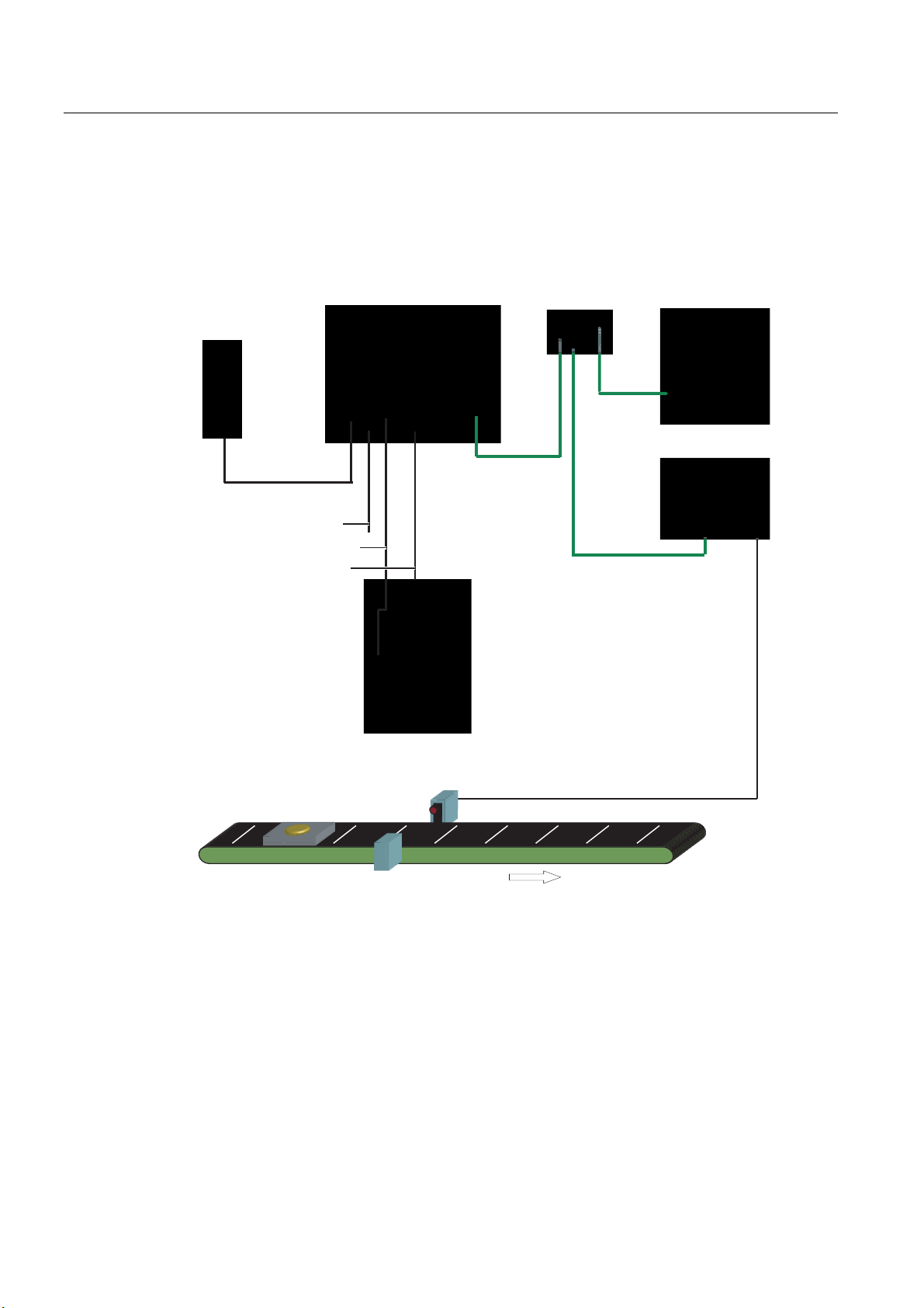
Figure 5-1 System configuration via digital I/O
System features:
• A PC/PG dedicated to adjustment is connected via the Ethernet port.
• The connection to an automation system is established via digital I/Os.
• The SIMATIC VS120 is controlled by the automation system via digital I/Os.
• The OK or N_OK results of the specimen are passed to the automation system via
digital I/Os.
Vision Sensor SIMATIC VS120
5-2 Operating Instructions, Edition 02/2006, A5E00757507-01
Page 45

Network and system integration
5.3 PROFIBUS DP system configuration
5.3 5.3 PROFIBUS DP system configuration
Acquisition and output of recognition values in a PROFIBUS DP environment
3RZHU
VXSSO\
3RZHUVXSSO\FDEOH
)XQFWLRQDOHDUWKLQJFDEOH
/LJKWLQJFDEOH
6HQVRUFDEOH
3URFHVVLQJXQLW
3*3&IRU
VHWXSVXSSRUW
5- (WKHUQHW
FDEOH
$XWRPDWLRQV\VWHP
352),%86b'3
6HQVRUKHDG
','2FDEOH
/('ULQJIODVK
2EMHFW
Figure 5-2 System configuration with PROFIBUS DP
System features:
• A PC/PG dedicated to adjustment is connected via the Ethernet port.
• The connection to an automation system is established via PROFIBUS DP.
• The SIMATIC VS120 is controlled by the automation system via PROFIBUS DP.
• The results from the specimen are output to the automation system via PROFIBUS DP.
Vision Sensor SIMATIC VS120
Operating Instructions, Edition 02/2006, A5E00757507-01
3KRWRHOHFWULFEDUULHU
&RQYH\RUXQLW
&RQYH\RUXQLW
5-3
Page 46
Network and system integration
5.4 PROFINET IO system configuration
5.4 5.4 PROFINET IO system configuration
Acquisition and output of recognition values in a PROFINET IO environment
3RZHU
VXSSO\
3RZHUVXSSO\FDEOH
)XQFWLRQDOHDUWKLQJFDEOH
/LJKWLQJFDEOH
6HQVRUFDEOH
3URFHVVLQJXQLW
6HQVRUKHDG
/('ULQJIODVK
6ZLWFK
3*3&IRU
DGMXVWPHQWVXSSRUW
$XWRPDWLRQV\VWHP
352),1(7,2
','2FDEOH
2EMHFW
&RQYH\RUXQLW
3KRWRHOHFWULFEDUULHU
&RQYH\RUXQLW
Figure 5-3 System configuration with PROFINET IO
System features:
• A PC / PG dedicated to adjustment is connected via the Ethernet (TCP/IP) and a switch.
• There is also a connection to a PROFINET IO compliant automation system via Ethernet
and a switch.
• The SIMATIC VS120 is controlled by the automation system.
• The results from the specimen are output to the automation system via PROFINET IO.
Vision Sensor SIMATIC VS120
5-4 Operating Instructions, Edition 02/2006, A5E00757507-01
Page 47
Network and system integration
5.5 System configuration with Ethernet or RS-232 over Com server
5.5 5.5 System configuration with Ethernet or RS-232 over Com server
Acquisition and output of recognition values with Ethernet (TCP / IP)
3RZHU
VXSSO\
3RZHUVXSSO\FDEOH
)XQFWLRQDOHDUWKLQJFDEOH
/LJKWLQJFDEOH
6HQVRUFDEOH
3URFHVVLQJXQLW
6HQVRUKHDG
/('ULQJIODVK
6ZLWFK
3*3&IRU
DGMXVWPHQWVXSSRUW
5-
(WKHUQHW
FDEOH
+0,
','2FDEOH
2EMHFW
Figure 5-4 System configuration with Ethernet (TCP/IP)
System features:
• The PC / PG for adjustment support is connected to the processing unit via a network.
• The SIMATIC VS120 is controlled by the HMI.
• The results from the specimen are output to the HMI.
Vision Sensor SIMATIC VS120
Operating Instructions, Edition 02/2006, A5E00757507-01
3KRWRHOHFWULFEDUULHU
&RQYH\RUXQLW
&RQYH\RUXQLW
5-5
Page 48

Network and system integration
5.5 System configuration with Ethernet or RS-232 over Com server
3RZHU
VXSSO\
3RZHUVXSSO\FDEOH
)XQFWLRQDOHDUWKLQJFDEOH
/LJKWLQJFDEOH
6HQVRUFDEOH
3URFHVVLQJXQLW
6HQVRUKHDG
/('ULQJIODVK
6ZLWFK
&RPVHUYHU
HJ:7
','2FDEOH
3*3&IRU
DGMXVWPHQWVXSSRUW
5-
(WKHUQHW
FDEOH
+0,
56
2EMHFW
&RQYH\RUXQLW
3KRWRHOHFWULFEDUULHU
&RQYH\RUXQLW
Figure 5-5 System configuration with RS-232 via Com server
System features:
• The PC / PG for adjustment support is connected to the processing unit via a network.
• The results are output to the HMI via the RS-232 port of the Com server, for example
W&T.
Vision Sensor SIMATIC VS120
5-6 Operating Instructions, Edition 02/2006, A5E00757507-01
Page 49

Installation
6.1 6.1 Installing the SIMATIC VS120 processing unit
1. For the location of the fixing holes, refer to the
VS120 Processing Unit
2. Mount the processing unit so that it is easily accessible for the operator
6.2 6.2 Installing the sensor head with LED ring flash
Notice
Aligning the optical axis
Align the optical axis of the sensor head vertical to the direction in which the object is
conveyed. Otherwise the image of the object will be distorted. The evaluation will be
inaccurate.
If the objects always pass the sensor head in the same position, the angle of the mid axis of
the objects to the vertical can be up to 45°.
Dimensional Drawing of the SIMATIC
6
Notice
Distance D between sensor and object
The ideal distance D between sensor and object depends on the type of sensor head. With
sensor heads with the order numbers (MLFB) below, the recommended distance D is as
follows:
• 6GF2 002-8DA01: 100 mm
• 6GF2 002-8EA01: 90 mm
Vision Sensor SIMATIC VS120
Operating Instructions, Edition 02/2006, A5E00757507-01
6-1
Page 50

Installation
6.2 Installing the sensor head with LED ring flash
There are two possible ways to install the LED ring flash:
• LED ring flash on the sensor head, parallel to the optical axis of the sensor head
6HQVRUKHDG
'
2EMHFW
&RQYH\RUXQLW
Figure 6-1 Components
How to mount the LED ring flash on the sensor head
The LED ring flash is supplied with two mounting brackets to allow it to be mounted on the
sensor head.
/('ULQJIODVK
1. Screw the mounting bracket onto the LED ring sensor
2. Push the sensor head through the LED ring sensor
3. Guide the mounting brackets into the grooves of the sensor head
4. Secure the mounting bracket with screws.
Vision Sensor SIMATIC VS120
6-2 Operating Instructions, Edition 02/2006, A5E00757507-01
Page 51

Installation
6.2 Installing the sensor head with LED ring flash
How to mount the sensor head
A mounting plate is supplied with the sensor head.
1. Insert the mounting plate in one of the grooves of the sensor head
2. Secure the sensor to your holder with a mounting plate
How to mount the LED ring flash beside the sensor head
No ring light flash is supplied to secure the LED ring flash beside the sensor head For
ordering information on a suitable ring flash holder, refer to the section
Accessories
in the
operating instructions.
1. Mount the sensor head on your holder
2. Secure the LED ring flash to the ring flash holder
3. Secure the ring light holder to your holder
• LED ring flash beside the sensor head, at an angle to the optical axis of the sensor head
Notice
LED ring flash beside the sensor head
If the object causes interfering reflections when the LED ring flash is mounted on the
sensor head, mount the LED ring flash beside the sensor head.
/('ULQJIODVK
Figure 6-2 Components with ring light
2EMHFW
&RQYH\LQJXQLW
6HQVRUKHDG
Vision Sensor SIMATIC VS120
Operating Instructions, Edition 02/2006, A5E00757507-01
6-3
Page 52

Installation
6.2 Installing the sensor head with LED ring flash
Vision Sensor SIMATIC VS120
6-4 Operating Instructions, Edition 02/2006, A5E00757507-01
Page 53

Connecting
7.1 7.1 Guidelines on installation and avoiding electrical interference
To avoid interference, you must shield your system. Low-frequency (LF) and high-frequency
(HF) interference signals can result in an incorrect response if the system is badly grounded
or not shielded.
Interference signals can be caused, for example, by
• Switching relays or contactors (large, fast changes in current or voltage and HF
interference signals);
• Different ground potentials between two parts of the system (LF interference signals)
Using / installing interference-proof cable
• Always use the supplied cable to connect the sensor head.
• All plug-in connections must be secured by screws or a locking mechanism.
• Signal lines must not run parallel to power cables. A separate cable channel must be
used with a minimum clearance of 50 cm from power cables.
7
Note
For more detailed information, refer to the installation manual SIMATIC S7-300
Programmable Controller, Hardware and Installation in the section on "Wiring".
7.2 7.2 Guidelines on installation when using PROFIBUS DP or PROFINET IO
If you are using PROFIBUS DP or PROFINET I/O to control the device and/or to transfer the
results the installation and configuration guidelines must be kept to.
Vision Sensor SIMATIC VS120
Operating Instructions, Edition 02/2006, A5E00757507-01
7-1
Page 54

Connecting
7.3 Connecting components
7.3 7.3 Connecting components
Connect the processing unit with the other components using the connectors on the front
panel.
The pinning of the connectors is described in the section: "Technical specifications" and with
the description of the supplied cable in section: "Scope of delivery/Spares/Accessories".
Caution
Do not connect or disconnect cables when the power supply is on.
Warning
Grounding the SIMATIC VS120 cancels the ungrounded configuration of the power unit.
Note
The DC load power supply must meet the following requirements:
Only a safe, isolated extra-low voltage of 24 V DC may be used as the load current supply.
Safe isolation can be implemented according to the requirements of:
- VDE 0100-410 / HD 384-4-41 S2 / IEC 60364-4-41 as protective extra low voltage with
safe isolation (PELV) or
- VDE 0805 / EN 60950 / IEC 60950 as safety extra-low voltage (SELV) or VDE 0106
Part 101.
The power supply chassis of the I/O and CPU must be connected to the power supply
chassis of the processing unit.
Vision Sensor SIMATIC VS120
7-2 Operating Instructions, Edition 02/2006, A5E00757507-01
Page 55

Connecting
7.3 Connecting components
Figure 7-1 Locations of the connection element
Wiring Connector label Type Number
of pins
Functional earth
Power supply IN 24 V DC Circular M12
Lighting unit LAMP Circular M12
Sensor head
(shielded cable)
I/O DI/DO D-sub 15 0.14 mm2 Socket
PROFIBUS DP DP D-sub 9 - Socket
Ethernet ETHERNET RJ45 8 - Socket
SENSOR HD D-sub 26 0.09 mm2 Socket
Screw-type
terminal
connector
connector
1 1.5 mm
4 0.56 mm2 Pin
4 0.23 mm2 Socket
Cable cross
section
2
Stranded
Type
conductor
Cable connection
• Read the guidelines on preventing electrical interference.
• Connect the processing unit to the sensor head and the lighting unit with the cables.
• Connect functional ground of the processing unit with chassis with a ring ∅ M5 and a
cable cross section of at least 1.5 mm
• Connect the processing unit to the 24 V DC load power supply with I = 2 A.
• Connect the PC/PG to the processing unit using an Ethernet cable.
• Arrange the cabling according to your configuration.
Vision Sensor SIMATIC VS120
Operating Instructions, Edition 02/2006, A5E00757507-01
2
.
7-3
Page 56

Connecting
7.3 Connecting components
Vision Sensor SIMATIC VS120
7-4 Operating Instructions, Edition 02/2006, A5E00757507-01
Page 57

Commissioning
8.1 8.1 Prerequisites
Notice
All activities are described based on the classic Windows Start menu.
If your Windows Start menu is not displayed in the classic style, change it as follows:
1. Right-click on the taskbar and select "Properties".
2. Change to the "Start Menu" tab and select the "Classic Start Menu" radio button.
3. Click "OK" to close the dialog box.
Requirements for commissioning:
• Administrator privileges
• Enabled JAVA JIT Compiler
8
Checking for administrator privileges
1. Click Start > Settings > Control Panel > Administrative Tools > Computer Management
2. Click on System > Local Users and Groups > Groups > Administrators
If you are included in the group of administrators, you have administrator privileges.
Otherwise contact your network administrator.
Vision Sensor SIMATIC VS120
Operating Instructions, Edition 02/2006, A5E00757507-01
8-1
Page 58

Commissioning
8.2 Overview of the steps in commissioning
Enabling the JAVA JIT compiler
1. Select Tools > Internet Options in the Internet Explorer and make the settings as shown
in the figure below:
Figure 8-1 Settings for the Java JIT compiler
8.2 8.2 Overview of the steps in commissioning
Step Activity
1 Turn on the VS120 processing unit
2
3 Establish and check the connections
4 Start adjustment support over the Internet Explorer
5 Adjust the sensor head using adjustment support
Establish an Ethernet connection between the VS120 processing unit and PG / PC:
2.1 Select the connection variant
2.2 Check if a proxy server is being used
2.3 If a proxy server is being used:
Change the proxy configuration of your Internet Explorer
Vision Sensor SIMATIC VS120
8-2 Operating Instructions, Edition 02/2006, A5E00757507-01
Page 59

Commissioning
8.3 Turn on the VS120 processing unit
8.3 8.3 Turn on the VS120 processing unit
Initial commissioning:
Turn on the power supply of the VS120 processing unit for its initial commissioning. The
VS120 processing unit then performs a self-test:
• Test of the Ethernet connection
• Function test of the sensor head
Note
During the initial commissioning, "Factory Settings Used" appears on the LCD display.
Confirm this with "OK.“
Once the self-test is completed, "Adjust" appears on the LCD display.
Normal mode:
Each time the SIMATIC VS120 starts up, the VS120 processing unit runs the following selftest:
• Test of the stored settings and model data
• Test of the Ethernet connection
• If appropriate, test of the connection to PROFINET IO
• If appropriate, test of the Ethernet RS-232 converter or TCP server and connection to the
PC / PG
• If appropriate, test of whether data can be exchanged with PROFIBUS DP
• Function test of the sensor head
• If appropriate, test of the connection for archiving model data
If the self-test completes without any errors, the main menu, the "Adjust" display or the RUN
menu is displayed on the LCD display depending on the status when the device was last
turned off.
• "Main" menu:
Vision Sensor SIMATIC VS120
Operating Instructions, Edition 02/2006, A5E00757507-01
8-3
Page 60

Commissioning
8.3 Turn on the VS120 processing unit
• "Adjust" displayed on the LCD display:
• "RUN" menu:
Note
Apart from controlling from the VS120 processing unit, you can also control
SIMATIC VS120 with the adjustment support.
Next step
Perform the activities described in the section
VS120 processing unit and PC / PG
.
Establish an Ethernet connection between the
Vision Sensor SIMATIC VS120
8-4 Operating Instructions, Edition 02/2006, A5E00757507-01
Page 61

Commissioning
8.4 Establish an Ethernet connection between the processing unit and PG / PC
8.4 8.4 Establish an Ethernet connection between the processing unit and
PG / PC
8.4.1 Select the connection variant
8.4.1.1 Connection variants
You can connect the VS120 processing unit via a direct connection or via a network with a
PC / PG. In all cases, the TCP/IP Ethernet protocol is used for communication.
Direct connection
• Operating the VS120 processing unit as a DHCP server
• Connecting the VS120 processing unit manually
Connection over a network
• Integrating the VS120 processing unit as a DHCP client in a network
• Integrating the VS120 processing unit as a device in a PROFINET IO network
Next step
Notice
Operating the VS120 processing unit in a network can interfere with the communication
in your network if you make certain settings in the Connect > Ports > Ethernet > IP Mode
menu. You should therefore only connect the VS120 processing unit to the network after
you have completed configuration and checked your settings carefully.
Select one of the connection variants from the next sections.
Vision Sensor SIMATIC VS120
Operating Instructions, Edition 02/2006, A5E00757507-01
8-5
Page 62

Commissioning
8.4 Establish an Ethernet connection between the processing unit and PG / PC
8.4.1.2 Operating the VS120 processing unit as a DHCP server
You want to do the following with the VS120 processing unit:
• Connect directly to the PC / PG
• Operate the VS120 processing unit as a DHCP server to assign the following addresses
of the processing unit automatically:
– IP address
– DNS server address
Notice
Under no circumstances connect the VS120 processing unit in this mode to an
existing DHCP server in the house network over a switch as you may disrupt the
operation of the house network. You can only implement an additional connection
from the PC to your previous network over a second network adapter in this PC.
Note
In this mode, you can connect up to four PCs to the VS120 processing unit via a
switch since a maximum of four IP addresses can be assigned automatically.
Procedure
1. Configure the VS120 processing unit as a DHCP server.
2. Configure your PC / PG as a DHCP client
3. Establish an Ethernet connection
Step 1: Configuring the VS120 processing unit as a DHCP server
1. After turning on the VS120 processing unit and after the self-test is completed, go to the
"Connect" menu and confirm with "OK".
2. Confirm the selected "Ports" menu command with "OK".
3. Change to the "Ethernet" menu and confirm with "OK"
4. Confirm the selected "IP Mode" menu command with "OK".
5. Select "DHCPSERV" and confirm with "OK"
Vision Sensor SIMATIC VS120
8-6 Operating Instructions, Edition 02/2006, A5E00757507-01
Page 63

Commissioning
8.4 Establish an Ethernet connection between the processing unit and PG / PC
Step 2: Configure your PC / PG as a DHCP client
1. Click Start > Settings > Network and Dial-up Connections
2. In the "Network and Dial-up Connections" dialog, select your active local area connection
to the network
3. Select "Properties" in the context menu and select the "Internet Protocol (TCP/IP)" entry.
4. Click the "Properties" button
5. Select the "Obtain an IP address automatically" radio button
Step 3: Establish the Ethernet connection
1. Establish an Ethernet connection between the VS120 processing unit and PC / PG. Use
a network cable of the type "Ethernet RJ-45 (crossover)"
Note
Instead of the network cable of the type "Ethernet RJ-45 (crossover)", you can also use a
network cable of the type "Ethernet RJ-45" with a switch for the connection between the
VS120 processing unit and the PC / PG.
Next step
Perform the activities described in the section
8.4.1.3 Connecting the VS120 processing unit manually
You want to do the following with the VS120 processing unit:
• Connect directly to the PC / PG
• Configure manually to change the IP address of the VS120 processing unit or to assign
an address yourself
Requirements
The PC / PG has the following default network setting that it cannot/should not be modified:
In the "Internet Protocol (TCP/IP) Properties" dialog, the "Use the following IP address" radio
button is selected.
You can check the setting by following the steps described in the section "Procedure for
checking the IP setting of the PC / PG".
Procedure
1. Check the IP setting of the PC / PG
Check the connection
.
2. Configure the VS120 processing unit manually
3. Establish an Ethernet connection
Vision Sensor SIMATIC VS120
Operating Instructions, Edition 02/2006, A5E00757507-01
8-7
Page 64

Commissioning
8.4 Establish an Ethernet connection between the processing unit and PG / PC
Step 1: Checking the IP setting of the PC / PG
1. Click Start > Settings > Network and Dial-up Connections
2. In the "Network and Dial-up Connections" dialog, select your active local area connection
to the network
3. Select "Properties" in the context menu and select the "Internet Protocol (TCP/IP)" entry.
4. Click the "Properties" button
5. Note down the displayed IP address and subnet mask of your PC / PG.
Step 2: Manual configuration of the VS120 processing unit
Notice
• The IP address of the VS120 processing unit must be in the same subnet as the IP
address of the PC.
• The default gateway is not necessary for a direct connection between the VS120
processing unit and a PC / PG
1. After turning on the VS120 processing unit and after the self-test is completed, go to the
"Connect" menu and confirm with "OK".
2. Confirm the selected "Ports" menu command with "OK".
3. Change to the "Ethernet" menu and confirm with "OK"
4. Confirm the selected "IP Mode" menu command with "OK".
5. Select "Manual" and confirm with "OK"
6. Change to the "IP Address" menu and confirm with "OK"
7. Now enter the IP address of the VS120 processing unit with the arrow keys and confirm
with "OK".
8. Change to the "IP Mask" menu and confirm with "OK"
9. Enter the subnet mask with the arrow keys and confirm with "OK"
Step 3: Establish the Ethernet connection
1. Establish an Ethernet connection between the VS120 processing unit and PC / PG. Use
a network cable of the type "Ethernet RJ-45 (crossover)"
Next step
Perform the activities described in the section
Vision Sensor SIMATIC VS120
8-8 Operating Instructions, Edition 02/2006, A5E00757507-01
Check the connection
.
Page 65

Commissioning
8.4 Establish an Ethernet connection between the processing unit and PG / PC
8.4.1.4 Integrating the VS120 processing unit as a DHCP client in a network
You want to do the following with the VS120 processing unit:
• Connect to the PC / PG over your existing network
• Operate as a DHCP client because the IP address configurations are assigned to the
PCs in the existing network by a DHCP server
Notice
Depending on your network structure, it may be necessary to inform the DHCP server of
the MAC address, the unique device identifier of the VS120 processing unit. You can see
these in the Connect > Ports > Ethernet > MAC Info menu.
Note
If your network administrator can assign a DNS name (Domain Name Service) for the
VS120 processing unit, you can address the device by name in much the same way as
an intranet server.
Procedure
1. Configure the VS120 processing unit as a DHCP client
2. Configure your PC as a DHCP client
3. Establish an Ethernet connection
Step 1: Configuring the VS120 processing unit as a DHCP client
1. After turning on the VS120 processing unit and after the self-test is completed, go to the
"Connect" menu and confirm with "OK".
2. Confirm the selected "Ports" menu command with "OK".
3. Change to the "Ethernet" menu and confirm with "OK"
4. Confirm the selected "IP Mode" menu command with "OK".
5. Select "DHCP" and confirm with "OK"
Step 2: Configuring your PC as a DHCP client
1. Click Start > Settings > Network and Dial-up Connections
2. In the "Network and Dial-up Connections" dialog, select your active local area connection
to the network
3. Select "Properties" in the context menu and select the "Internet Protocol (TCP/IP)" entry.
4. Click the "Properties" button
5. Select the "Obtain an IP address automatically" radio button
Vision Sensor SIMATIC VS120
Operating Instructions, Edition 02/2006, A5E00757507-01
8-9
Page 66

Commissioning
8.4 Establish an Ethernet connection between the processing unit and PG / PC
Step 3: Establish the Ethernet connection
1. Establish an Ethernet connection between your PC and your existing network. Use a
network cable of the type "Ethernet RJ-45"
2. Establish an Ethernet connection between the VS120 processing unit and your existing
network. Use a network cable of the type "Ethernet RJ-45"
Next step
Follow the steps described in the section
Check whether a proxy server is being used
.
8.4.1.5 Integrating the VS120 processing unit as a device in a PROFINET IO network
You want to do the following with the VS120 processing unit:
• Connect to the PC / PG over your existing PROFINET IO network
• Integrate the unit as a device in a PROFINET IO network because the IP configuration
will be assigned by the PROFINET IO controller
Notice
The IP configuration of the VS120 processing unit is set in STEP 7. It is not possible to
set the parameters on the VS120 processing unit.
Procedure
1. Configure the VS120 processing unit as a PROFINET IO device
2. Make the parameter settings for the IP configuration of the VS120 processing unit in
STEP 7.
3. Integrate your PC in the PROFINET IO network
4. Establish an Ethernet connection
Step 1: Configuring the VS120 processing unit as a PROFINET IO device
1. After turning on the VS120 processing unit and after the self-test is completed, go to the
"Connect" menu and confirm with "OK".
2. Confirm the selected "Ports" menu command with "OK".
3. Change to the "Ethernet" menu and confirm with "OK"
4. Confirm the selected "IP Mode" menu command with "OK".
5. Select "PNIO" and confirm with "OK"
Note
The VS120 processing reboots after the IP mode is changed to "PNIO".
Vision Sensor SIMATIC VS120
8-10 Operating Instructions, Edition 02/2006, A5E00757507-01
Page 67

Commissioning
8.4 Establish an Ethernet connection between the processing unit and PG / PC
Step 2: Setting the parameters for the IP configuration of the VS120 processing unit in STEP 7
For a description, refer to the section:
in HW Config
Integrating the PROFINET IO device SIMATIC VS120
Step 3: Integrating your PC in the PROFINET IO network
Notice
• The network attachment must not have an IP address that is already being used in your
network
• The IP address of the PC must be in the same subnet as the IP address of the VS120
processing unit. If necessary, the port configuration of the PC must be adapted
1. Click Start > Settings > Network and Dial-up Connections
2. In the "Network and Dial-up Connections" dialog, select the existing local area connection
to the network. This must have the status "Enabled".
3. Select "Properties" in the context menu and select the "Internet Protocol (TCP/IP)" entry.
4. Click the "Properties" button
5. Select the "Use the following IP address" radio button
6. Adapt the "IP address" and "Subnet mask" to your PROFINET IO network
Step 4: Establish the Ethernet connection
1. Establish an Ethernet connection between your PC and a switch in your existing
PROFINET IO network. Use a network cable of the type "Ethernet RJ-45"
2. Establish an Ethernet connection between the VS120 processing unit and your existing
network. Use a network cable of the type "Ethernet RJ-45"
Next step
Follow the steps described in the section
Vision Sensor SIMATIC VS120
Operating Instructions, Edition 02/2006, A5E00757507-01
Check whether a proxy server is being used
.
8-11
Page 68

Commissioning
8.4 Establish an Ethernet connection between the processing unit and PG / PC
8.4.2 Check whether a proxy server is being used
If the VS120 processing unit is used in a network with proxy servers, the following problems
can occur:
• The address entered for the VS120 processing unit is not known to the Internet Explorer
• Error message when starting adjustment support
You should therefore check whether or not a proxy server is entered in the "Local Area
Network (LAN) Settings" dialog of the Internet Explorer.
Procedure
1. Start the Internet Explorer and select the menu command Tools > Internet Options...
2. Click on the "Connections" tab
3. Click on the "LAN Settings" button in the "Local Area Network (LAN) settings" group box.
4. If the "Use a proxy server" check box is selected in the "Proxy server" group box, a proxy
server is used and the "Advanced" button is enabled.
Result
Next step
A proxy server is used in the Internet Explorer if one of the following conditions is met:
• The "Use a proxy server for your LAN" check box is enabled in the "Proxy server" group
box
• The "Advanced" button is enabled.
• Follow the steps described in the section
Explorer
• If no proxy server is used in the Internet Explorer, skip to the steps described in the
section
only if a proxy server is used in the Internet Explorer
Check the connection
Change the proxy configuration of your Internet
Vision Sensor SIMATIC VS120
8-12 Operating Instructions, Edition 02/2006, A5E00757507-01
Page 69

Commissioning
8.4 Establish an Ethernet connection between the processing unit and PG / PC
8.4.3 Change the proxy configuration of your Internet Explorer
Change the proxy configuration of your Internet Explorer only if a proxy server is used in the
Internet Explorer.
Procedure
1. Start the Internet Explorer and select the menu command Options > Internet Options
2. Click on the "Connections" tab
3. Click on the "LAN Settings" button in the "Local Area Network (LAN) settings" group box.
4. In the next dialog "Local Area Network (LAN) Settings", clear all the check boxes and
confirm with OK
Figure 8-2 Settings for the local area network
As an alternative, if the "Use a proxy server for your LAN" check box needs to be
selected, click the "Advanced" button in the "Proxy server" area and enter the current IP
address of the VS120 processing unit in the "Exceptions" area in the "Proxy Settings"
dialog.
Next step
Vision Sensor SIMATIC VS120
Operating Instructions, Edition 02/2006, A5E00757507-01
Note
You can also enter computer names in the "Exceptions" area. The computer name is
resolved into a static or dynamic IP address by the DNS server in the network.
Perform the activities described in the section
Check the connection
.
8-13
Page 70

Commissioning
8.4 Establish an Ethernet connection between the processing unit and PG / PC
8.4.4 Check the connection
Checking the connection tells you whether or not the configured Ethernet connection
between the PC and the VS120 processing unit is working.
You can only start adjustment support from your Internet Explorer and operate the VS120
processing unit from your PC after you have checked the connection.
Requirements
• The VS120 processing unit was either integrated in your existing network or connected
directly to a PC
• The network cable is connected to the VS120 processing unit
• The VS120 processing unit is connected to a 24 V DC power supply unit and is being
supplied with power
• The VS120 processing unit self-test is completed
Procedure
1. Make sure that the VS120 processing unit and PC are correctly connected to the existing
network or are connected together using an Ethernet crossover cable
Result
2. After turning on the VS120 processing unit and after the self-test is completed, go to the
"Connect" menu and confirm with "OK".
3. Confirm the selected "Ports" menu command with "OK".
4. Change to the "Ethernet" menu and confirm with "OK"
5. Change to the "IP Address" menu and confirm with "OK"
6. Note down the IP address displayed on the VS120 processing unit
7. Open the command prompt on the PC with Start > Run and enter the program name
"cmd".
8. In the command prompt, enter the following:
ping <IP address or name of the VS120 processing unit>
Example: ping 192.168.0.42
9. Confirm your entry by pressing the enter key on the keyboard
If the connection from the PC to the VS120 processing unit exists, 4 packets are first sent
from the PC to the processing unit as shown above and then 4 packets are returned from the
VS120 processing unit to the PC.
The reply from the VS120 processing unit appears on the PC, for example, as follows:
Reply from 192.168.0.2 bytes=32 time<10ms TTL=255
Reply from 192.168.0.2 bytes=32 time<10ms TTL=255
Reply from 192.168.0.2 bytes=32 time<10ms TTL=255
Reply from 192.168.0.2 bytes=32 time<10ms TTL=255
This is followed by the ping statistics for 192.168.0.2.
Vision Sensor SIMATIC VS120
8-14 Operating Instructions, Edition 02/2006, A5E00757507-01
Page 71

Commissioning
8.5 Start setup support over the Internet Explorer
Next step
• If you receive a reply from the VS120 processing unit on the PC, follow the steps
described in the section
• If you do not receive a reply from the VS120 processing unit, repeat the steps described
in the section
and/or contact your network administrator
Establish connection and between VS120 processing unit and PG / PG
Start adjustment support over the Internet Explorer
8.5 8.5 Start setup support over the Internet Explorer
To be able to work with the adjustment support implemented on the VS120 processing unit,
establish a connection from the Internet Explorer to the adjustment support
Requirements
The section
completed successfully. As described in the section
established a confirmed connection from the VS120 processing unit to the PC / PG.
Establishing a connection between the VS120 processing unit and PC / PG
Check the connection
, you have
was
Procedure
1. Start the PC
2. Turn on the power supply of the VS120 processing unit. Once the self-test has
completed, go to "Adjust" in the LSD display
3. Press the OK button of the VS120 processing unit. The IP address appears on the LCD
display
4. Note down the IP address of the VS120 processing unit
5. Start the Internet Explorer
6. In the "IP address" input box, enter the IP address of the VS120 processing unit.
7. Press the enter key on the keypad
Vision Sensor SIMATIC VS120
Operating Instructions, Edition 02/2006, A5E00757507-01
8-15
Page 72

Commissioning
8.5 Start setup support over the Internet Explorer
Result
The start page of the "Vision Sensor SIMATIC VS120" adjustment support appears in the
Internet Explorer. From here, you have access to all functions required to test the models.
Figure 8-3 Home
The adjustment support is started with "Adjust Sensor". The SIMATIC VS120 then
automatically blocks operator input at the VS120 processing unit. The LCD display of the
VS120 processing unit displays the message: "Settings controlled by Web".
Next step
Follow the steps described in the section
Vision Sensor SIMATIC VS120
8-16 Operating Instructions, Edition 02/2006, A5E00757507-01
Adjust the sensor head using adjustment support
.
Page 73

Commissioning
8.6 Adjust the sensor head using setup support
8.6 8.6 Adjust the sensor head using setup support
Before you commission the "SIMATIC VS120 Vision Sensor", you must adjust the sensor
head correctly You do this with the "SIMATIC VS120 Vision Sensor" adjustment support that
is available in the Internet Explorer. The adjustment support shows you an image as seen by
the sensor head.
Requirements
Procedure
Note
Online Help
At the bottom right of each page of adjustment support, you will see a “Help” button with
which you can call up online help at any time. The relevant help text of the online help opens
depending on the currently open dialog.
The Start Page of the "SIMATIC VS120 Vision Sensor" adjustment support was started over
the Internet Explorer
1. On the start page of the adjustment support, click on "Sensor Adjustment". The
"Adjustment" user interface opens. The sensor head view is displayed and updated
several times per second.
Figure 8-4 Adjustment
Vision Sensor SIMATIC VS120
Operating Instructions, Edition 02/2006, A5E00757507-01
8-17
Page 74

Commissioning
8.6 Adjust the sensor head using setup support
2. Position an object below the sensor head
3. Set the displayed image to that it is sharp by adjusting the distance between the end of
the sensor head and the model correctly
4. Secure the sensor head and then check the image sharpness again
5. Make sure that the triggering is exact and the content of the image has as much contrast
as possible
If necessary, correct the settings or use the automatic shutter mode. You can set the
following parameters:
– Exposure settings
– Trigger settings
– Precision
– Distortion
Notice
If Shutter is set to Auto, the model must remain fully in the image for at least 100 ms.
Result
6. Click the "Apply" button to save the settings.
Note
If you have too many errors, clean the lens and diffuser with a lint-free cloth.
You have successfully commissioned "SIMATIC VS120 Vision Sensor". You can now train
and process your models for your application. Refer to the section
information.
Operation
for more
Vision Sensor SIMATIC VS120
8-18 Operating Instructions, Edition 02/2006, A5E00757507-01
Page 75

Operation
9.1 9.1 Overview
There are two ways of operating the SIMATIC VS120:
• From the VS120 processing unit, see the section:
unit
• Using adjustment support See the section
You can set and change all parameter settings with adjustment support on the PC.
Configuration on the VS120 processing unit itself is limited.
9.2 9.2 Working with the processing unit
9.2.1 Introduction
9
Working with the VS120 processing
Working with adjustment support on the PC
The display of the VS120 processing unit is used to show the coordinates and the orientation
of the test object currently being viewed and the associated quality value. You can also
navigate between the menus and make entries in the LCD display.
Example of an LCD display:
M 01 RUN N
X=−299.0
Y=0.0
↓ OK:Info
Five levels are implemented as selection menus or displays:
• Adjust
• Connect
• RUN
• Options
• Maintain
Vision Sensor SIMATIC VS120
Operating Instructions, Edition 02/2006, A5E00757507-01
9-1
Page 76

Operation
9.2 Working with the processing unit
9.2.2 Adjust
"Adjust" display
The Adjust LCD display displays the current IP address.
9.2.3 Connect
"Connect" menu
The following schematics provide you with an overview of all the parameters of the SIMATIC
VS120 that can be set in the Connect menu.
Vision Sensor SIMATIC VS120
9-2 Operating Instructions, Edition 02/2006, A5E00757507-01
Page 77

Operation
9.2 Working with the processing unit
Figure 9-1 Structure of the Connect menu
Vision Sensor SIMATIC VS120
Operating Instructions, Edition 02/2006, A5E00757507-01
9-3
Page 78

Operation
9.2 Working with the processing unit
Figure 9-2 Structure of the Connect menu continued
"Connect" parameter menu
Parameters
Port
Pulsetime Ports>DI/DO 5 to 999 30 Pulse time of the digital outputs OK,
Address
(not active if IP
Mode = PNIO)
Timeout
(not active if IP
Mode = PNIO)
Pulsetime
(not active if IP
Mode = PNIO)
DevName
(only active if IP
Mode = PNIO)
Timeout
(only active if IP
Mode = PNIO)
Pulsetime
(only active if IP
Mode = PNIO)
IP mode Ports>Ethernet Assignment of the IP address to the
Path Possible Values Default Meaning
N_OK in ms on the DI/DO interface
Ports>DP 1 to 125 7 Address on PROFIBUS DP
Ports>DP 100 to 2000 500 Handshake monitoring time in ms
Ports>DP 5 to 999 30 Pulse time of the digital outputs OK,
N_OK in ms when output is via
PROFIBUS DP
Ports>PNIO String (0 to 9, A to
Z, a to z, ".", "-").
The string must
match the
conventions of the
domain name
system.
Ports>PNIO 100 to 2000 500 Handshake monitoring time in ms
Ports>PNIO 5 to 999 30 Pulse time of the digital outputs OK,
VS120 Name of the device on PROFINET
Note: PROFINET is not case sensitive
N_OK in ms when output is via
PROFINET IO
Note: For the pulse time, select a higher
value than for the update time of the
PROFINET IO system in HW Config.
processing unit in the network.
Vision Sensor SIMATIC VS120
9-4 Operating Instructions, Edition 02/2006, A5E00757507-01
Page 79

Operation
9.2 Working with the processing unit
Parameters
Port
IP Address Ports>Ethernet xxx.xxx.xxx.xxx
IP Mask
(not active if IP
Mode = DHCP)
Gateway
(not active if IP
Mode = DHCP)
MAC Info Ports>Ethernet Cannot be
IP Address Ports>
IP port Ports>
Timeout Ports>
Path Possible Values Default Meaning
(xxx = 0 to 255)
Ports>Ethernet xxx.xxx.xxx.xxx
(xxx = 0 to 255)
except:
0.0.0.0
255.255.255.255
Ports>Ethernet xxx.xxx.xxx.xxx
(xxx=0 to 255)
modified
xxx.xxx.xxx.xxx
TCP/RS232
TCP/RS232
TCP/RS232
(xxx=0 to 255)
1 to 65535 8000 IP port of the Ethernet RS-232 converter
0 to 3600 0
192.168.0.42 IP address of the processing unit
(An IP address consists of four numbers
separated by periods with each number
being in a range from 0 to 255.)
255.255.255.0 The subnet mask indicates which part of
the IP address specifies the network and
which part specifies the VS120
processing unit:
For xxx.xxx.xxx.xxx, binary requires that
the left part be made up of ones without
a gap and the right part be made up of
zeros without a gap. Example:
11111111.10100000 is not permitted.
192.168.0.255 IP address of the network node that can
establish connections outside of the
current subnet
Device-dependent The MAC address (Media Access
Control) is the hardware address of each
network device and is used to identify
the device uniquely in the network.
192.168.0.43 IP address of the Ethernet RS-232
converter or of the PC/PG on which a
TCP server runs.
or of the PC/PG on which a TCP server
runs.
• 0: There is no transfer of cyclic
monitoring frames to determine
whether the connection still exists
between the processing unit and the
Ethernet RS-232 converter or the
PC/PG on which a TCP server runs.
• Otherwise: Time in seconds after
which a monitoring frame is sent to
determine whether the connection
still exists between the processing
unit and the Ethernet RS-232
converter or the PC/PG on which a
TCP server runs. The check is
implemented by sending the "Idling
string" ("IdleStr." menu) to the
recipient at the intervals set with the
parameter. If the check fails, an error
is output (only when the processing
unit is in RUN) and the connection is
reestablished.
Vision Sensor SIMATIC VS120
Operating Instructions, Edition 02/2006, A5E00757507-01
9-5
Page 80

Operation
9.2 Working with the processing unit
Parameters
Port
IdleStr. Ports>
IP Address Ports>
Port Ports>
Timeout Ports>
Path Possible Values Default Meaning
TCP/RS232
Archive
Archive
Archive
Freely selectable
character string
xxx.xxx.xxx.xxx
(xxx=0 to 255)
1 to 65535 8765 Corresponding port of this server
0 to 3600 10
\r\n String to determine whether the
connection still exists between the
processing unit and the Ethernet RS-232
converter or the PC/PG on which a TCP
server runs. It is transferred cyclically.
Select this so that the recipient can
clearly distinguish it from the generated
results.
The string can be a maximum of 100
bytes.
192.168.0.45 IP address of the server for diagnostic
information
• 0: There is no transfer of cyclic
monitoring frames to check the
connection between processing unit
and server.
• Otherwise: Time in seconds after
which a monitoring frame is sent to
check the connection between
processing unit and server. If the
server does not respond to this
frame within the monitoring time, an
error is output (only when the
processing unit is in RUN) and the
connection is reestablished.
Parameters
Integrate
Source Integrate>
Edge
(only if Source=
TCP/RS-232)
String
(only if Source=
TCP/RS-232)
Debounce Integrate>
Path Possible Values Default Meaning
Trigger
Integrate>
Trigger
Integrate>
Trigger
Trigger
• DI/DO
• DP or PNIO
• TCP/RS-232
• Rising
• Falling
ASCII characters T If the string specified here is sent over
0 to 9999 ms 0 ms The function indicates the period for
DI/DO Here, you set the port over which the
trigger signal is sent to the processing
unit.
Rising The function indicates whether the
trigger is on a rising or falling edge.
the RS-232 port of an RS-232 Ethernet
converter or a TCP server, the
processing unit generates a trigger
signal.
which triggers are ignored due to
debouncing.
Vision Sensor SIMATIC VS120
9-6 Operating Instructions, Edition 02/2006, A5E00757507-01
Page 81

Operation
9.2 Working with the processing unit
Parameters
Integrate
Delay Integrate>
DelaySrc Integrate>
DP(S7) or
PNIO(S7)
(only if Control DP
or PNIO)
DP or PNIO
(only if Control DP
or PNIO)
Manual Integrate>
Output Integrate
OK/N_OK Integrate
Control Integrate
DiagImage Integrate
DiagReport Integrate
Path Possible Values Default Meaning
Trigger
Trigger
Integrate>
Trigger>
DelaySrc
Integrate>
Trigger>
DelaySrc
Trigger>
DelaySrc
• 0 to 9999 ms
for normal
triggers
• 0 to 9999950
µs with a fast
trigger or if
DelaySrc is not
manual
• Manual
• DP(S7) or
PNIO(S7)
• DP or PNIO
- - The trigger delay is received through the
- - The trigger delay is received by the
- - Editable values are used in the delay.
• DP or PNIO
• TCP/RS-232
• None
• DP or PNIO
• DI/DO
• None
• DP or PNIO
• DI/DO
• None
• Archives
• None
• Archives
0 ms This is where you enter the time by
which the trigger signal should be
delayed.
Note:
If DelaySrc is not manual, the values
received via DP / PNIO are displayed
here. They cannot be edited.
Manual Note:
• DP(S7) corresponds to
PROFIBUS DP with S7 format (big
endian format)
• DP corresponds to PROFIBUS DP
with Intel format (little endian format)
DP(S7) or PNIO(S7) user data interface
from the controller in S7 format.
controller over the user data interface
DP or PNIO in Intel format.
None This is where you enter the interface via
which the results are output.
DI/DO Here, you specify the interface over
which the result bits OK and N_OK are
output.
DI/DO Here you specify the port for the DISA,
SEL0, SEL1, SEL2, SEL3, RES, IN_OP,
TRD, RDY signals.
None This is where you specify if the
diagnostic images should be sent to a
server.
None This is where you specify if the
diagnostic reports should be sent to a
server.
Vision Sensor SIMATIC VS120
Operating Instructions, Edition 02/2006, A5E00757507-01
9-7
Page 82

Operation
9.2 Working with the processing unit
Parameters
Output
Encoding Output
Byte order
(only if Encoding =
Binary)
Format (only if
Encoding = ASCII)
Position Output
Sub-ROIs Output 0 … 16 16 This is where you enter the number of
Path Possible Values Default Meaning
Output
Output
• Binary
• ASCII
• S7
• Intel
• CSV
• Fix
• Absolute
• Trained
Binary The results for the main ROI and sub-
ROI are sent as binary data or ASCII
strings through the output interface set
in Integrate>Output
S7 Specifies the byte sequence for data
types greater than 8 bits.
S7 format:
Big endian (for a data type greater than
8 bits, the low byte is at the most
significant byte position.)
Intel format:
Little endian (for a data type greater than
8 bits, the low byte is at the least
significant byte position.)
CSV This is where you enter the format for
your output data.
• CSV: Send in CSV format
• Fix: Send individual results with a
fixed length of 12 characters
Absolute This is where you specify the reference
point.
Absolute:
The position of all ROIs are output as
absolute in relation to the image center
Trained::
The position of the main ROI is output
relative to its position at training based
on the image center.
The position of the sub-ROI is output
relative to its position at training based
on the center of the main ROI.
Note:
This parameter only relates to the
results to be transferred and not to the
displayed results from the screen and
applets.
sub-ROIs that you wish to transfer.
Vision Sensor SIMATIC VS120
9-8 Operating Instructions, Edition 02/2006, A5E00757507-01
Page 83

Operation
9.2 Working with the processing unit
9.2.4 RUN
RUN menu
The following table shows the menus of the RUN menu level.
Menu Meaning
Model Select the model number
Note:
May also be model set depending on the configuration.
STOP Stop processing and change to the STOP menu level
QLimit Enter the quality value for the evaluation as a percentage.
Note:
The display is only visible if you are not working with model sets.
Info Information function
ResetStat Resets all statistical information.
Vision Sensor SIMATIC VS120
Operating Instructions, Edition 02/2006, A5E00757507-01
9-9
Page 84

Operation
9.2 Working with the processing unit
Structure of the Info display for a model from the RUN menu
STOP
−Limit
Q
>Info
ESC ↓↑ OK
M 02 OK
=0
=0.000%
1/14 ↓ OK
M 02 WARN
=0
=0.000%
2/14 OK
M 02 N_OK
=0
=0.000%
3/14 OK
M 02 Curr.
Cycletime
=0ms
4/14 OK
M 02 Cycle
min=0.0ms
max=0.0ms
5/14 OK
M 02 Trig.
Too Fast
=0
6/14 → OK
M 02 Trig.
Too Fast
=0.000%
6/14 ← OK
M 02 Angle
min=0.0
max=0.0
10/14 OK
M 02 ROI Pos
cx=96
cy=94
11/14 OK
M 02 ROI Dim
width=310
height=298
12/14 OK
DHCP−IP:
141.73.
11.117
13/14 ↑ OK
Transient
Errors
=1
14/14 ↑ OK
M 02 Qual.
min=0.0%
max=0.0%
7/14 OK
M 02 X−Pos
min=0.0
max=0.0
8/14 OK
M 02 Y−Pos
min=0.0
max=0.0
9/14 OK
Figure 9-3 Info display for a model from the RUN menu
Note
"Transient Errors", the last menu command in the RUN menu, only appears when an error
occurs.
Vision Sensor SIMATIC VS120
9-10 Operating Instructions, Edition 02/2006, A5E00757507-01
Page 85

Operation
9.2 Working with the processing unit
Sequence of tasks in the RUN menu for a model based on the example of a model with number 2:
Step Display Activity
1
STOP
Q−Limit
> Info
Select "Info" on the processing unit at the "RUN" menu level using
the ⇓ and ⇑ arrow keys and press "OK". This opens the first Into
screen.
ESC ↓↑ OK
2
M 02 OK
=3226
=99.907%
Using the arrow buttons ⇓ and ⇑, you can display further Info
screens. Pressing "OK" returns you to the highest hierarchy level
of the "RUN" menu.
1/14 ↓ OK
Step Display Meaning
1
M 02 OK
=3226
=99.907%
1/14 ↓ OK
Since the last processing start, the pattern search for model 2 was
performed successfully in 3226 image recordings. This
corresponds to 99.907% of all images processed since processing
last started.
2
M 02 WARN
=6
=0.194%
6 examinations were below the warning limit since the last start of
processing. This corresponds to 0.194 % of all images processed
since processing last started.
2/14 OK
3
M 02 N_OK
=3
=0.093%
3 specimens could not be identified as model 2 since processing
started. This corresponds to 0.093 % of all images processed
since processing last started.
3/14 OK
4
M 02 Curr.
Cycletime
The required processing time (cycle time) for the specimen
currently under examination is 300 ms.
=300ms
4/14 OK
5
M 02 Cycle
min=120ms
Since the beginning of the statistical analysis for model 02, the
shortest evaluation time was 120 ms and the longest 276 ms.
max=276ms
5/14 OK
Vision Sensor SIMATIC VS120
Operating Instructions, Edition 02/2006, A5E00757507-01
9-11
Page 86

Operation
9.2 Working with the processing unit
Step Display Meaning
6
M 02 Trig.
Too Fast
=0
6/14 ← OK
7
M 02 Qual.
min=85%
M 02 Trig.
Too Fast
=0.000%
Absolute and relative number of image
processing procedures during which the
next trigger signal came too fast
6/14 ← OK
.
Since the beginning of the statistical analysis for the model 02, the
lowest quality value was 85% and the highest 99%.
max=99%
7/14 OK
8
M 02 X−Pos
min=−222
max=233
Since the beginning of the statistical analysis for model 02, the
lowest x coordinate of the target rectangle was -222 and the
highest 233.
8/14 OK
9
M 02 Y−Pos
min=−14
max=89
Since the beginning of the statistical analysis for model 02, the
lowest y coordinate of the target rectangle was -14 and the highest
89.
9/14 OK
10
M 02 Angle
min=−120.1
Since the beginning of the statistical analysis for the model 02, the
lowest roll angel was -120.1° and the highest 179.3°.
max=179.3
10/14 OK
11
M 02 ROI Pos
cx=−2
For model 02, the midpoint of the target rectangle has the following
coordinates: x=-2, y=4
cy=4
11/14 OK
12
M 02 ROI Dim
width=101
For model 02, the target rectangle has the following dimensions:
Width=101, Height=102
height=102
12/14 OK
Vision Sensor SIMATIC VS120
9-12 Operating Instructions, Edition 02/2006, A5E00757507-01
Page 87

Operation
9.2 Working with the processing unit
Step Display Meaning
13
ManuelIP:
192.168.
Display of the IP address of the processing unit in the network.
0.42
13/14 OK
14
Transient
Errors
Connection interrupted in the PROFIBUS DP or PROFINET IO
network.
=1
14/14 ↑ OK
Vision Sensor SIMATIC VS120
Operating Instructions, Edition 02/2006, A5E00757507-01
9-13
Page 88

Operation
9.2 Working with the processing unit
Structure of the Info display for a model set from the RUN menu
STOP
Q−Limit
>Info
ESC OK
S 02 OK
=3226
=99.907%
1/8 ↓ OK
S 02 WARN
=6
=0.194%
2/8 OK
S 02 N_OK
=3
=0.093%
3/8 OK
S 02 Curr.
Cycletime
=300ms
4/8 OK
S 02 Cycle
min=120ms
max=276ms
5/8 OK
S 02 Trig.
Too Fast
=0
6/9 → OK
ManuelIP:
192.168.
0.42
7/8 OK
Transient
Errors
=1
8/8 ↑ OK
Figure 9-4 RUN menu for a model set
M 02 Trig.
Too Fast
=0.000%
6/9 ← OK
Note
"Transient Errors", the last menu command in the RUN menu, only appears when an error
occurs.
Vision Sensor SIMATIC VS120
9-14 Operating Instructions, Edition 02/2006, A5E00757507-01
Page 89

Operation
9.2 Working with the processing unit
9.2.5 Options
Options menu
The following schematics provide you with an overview of all the parameters of the SIMATIC
VS120 that can be set in the Options menu.
Figure 9-5 Structure of the options menu
Vision Sensor SIMATIC VS120
Operating Instructions, Edition 02/2006, A5E00757507-01
9-15
Page 90

Operation
9.2 Working with the processing unit
Options parameter menu
Parameters
Light
Type Light
Path Possible Values Default Meaning
• IR
• Red
• Other
Red Here, you enter the type of illumination
being used.
Parameters
Diagnostics
Buffer Diagnose>
Reasons Diagnose>
Record Diagnose>
Save Next Diagnose>
Buffer Diagnose>
Save Next Diagnose>
Entries Diagnose>
Path Possible Values Default Meaning
Logging>
Images
Logging>
Images
Logging>
Images
Logging>
Images
Logging>
Report
Logging>
Report>
Permanent
Logging>
Report>
Permanent
• Ring
• Stack
• Trigger
• N_OK
• OK
• WARN
• Train
• Image
• +/- 1 Image:
• On
• Off
• Ring
• Stack
• On
• Off
10 to 2000 2000 Number diagnostic data records that can
Ring
N_OK This is where you specify what causes
Image
Off
Ring
Off As soon as the function is enabled, as
• Type of image buffer:·
• Ring: When the buffer contains 6
entries, entries 1,2 ... are overwritten.
• Stack: When the buffer contains 6
entries, no further entries are made.
an image to be saved.
• Image: If one or more of the causes
listed above occurs, the current
image is saved.
• +/- 1 Image: Not only the current
image but also the previous and next
image are saved.
• On: The image belonging to the next
NOK event is saved permanently in
the EEPROM.
• Ring: When the diagnostic buffer
contains 5000 entries, entries 1,2 ...
are overwritten.
• Stack: When the diagnostic buffer
contains 5000 entries, no further
entries are made.
many diagnostic entries as you specify
in “Entries” are saved in the EEPROM.
Existing entries are deleted when you
switch over to On. If the diagnostic
buffer in the EEPROM reaches the
number of permanently storable
diagnostic data records, no further
entries are made.
Note: Deleting takes several seconds.
be stored on the EEPROM
Vision Sensor SIMATIC VS120
9-16 Operating Instructions, Edition 02/2006, A5E00757507-01
Page 91

Operation
9.2 Working with the processing unit
Parameters
Diagnostics
Clear Diagnose>
Timebase Diagnose>
SNTP IP
(only when
Timebase= SNTP)
Update Diagnose>
Path Possible Values Default Meaning
Logging>
Report>
Permanent
Logging
Diagnose>
Logging
Monitor
- - Delete all the diagnostic entries stored
on the EEPROM
Note: Deleting takes several seconds.
• PC
• SNTP
xxx.xxx.xxx.xxx
(xxx=0 to 255)
• On
• Off
PC Here, you specify the source for the time
stamp of the diagnostic events.
192.168.0.44 IP address of the SNTP server
On This is where you specify if diagnostic
images, reports and a current image is
to be displayed in processing mode.
• On: Display
• Off: Not displayed
Vision Sensor SIMATIC VS120
Operating Instructions, Edition 02/2006, A5E00757507-01
9-17
Page 92

Operation
9.2 Working with the processing unit
9.2.6 Maintain
Maintain menu
The following schematics provide you with an overview of all the parameters of the SIMATIC
VS120 that can be set in Maintain.
0DLQWDLQ
Figure 9-6 Structure of the Maintain menu
Maintain parameter menu
Parameters
Maintain
Delete Maintain>
FactoryS Maintain>
Restart Maintain>
Path Possible Values Default Meaning
Delete
FactoryS
Restart
'HOHWH
)DFWRU\6
5HVWDUW
Model 01 to model
64
• ESC
• OK
• ESC
• OK
01 This function deletes individual models
- This function resets the VS120
processing unit to the factory settings
and restarts it.
- This function restarts the VS120
processing unit.
Vision Sensor SIMATIC VS120
9-18 Operating Instructions, Edition 02/2006, A5E00757507-01
Page 93

Operation
9.3 Working with setup support
9.3 9.3 Working with setup support
9.3.1 Introduction
Notice
Possible data loss!
The editing data is lost if the Internet Explorer or the input screens are turned off without first
saving the data because the application does not have session memory.
You should therefore always save your data to avoid losing it.
Note
Online Help
At the bottom right of each page of adjustment support, you will see a “Help” button with
which you can call up online help at any time. The relevant help text of the online help opens
depending on the currently open dialog.
Open the Start Page of the adjustment support in the Internet Explorer, refer to the section
"Commissioning using adjustment support on the PG / PC with installed Internet Explorer".
With “Adjust Sensor”, you display the user interface of the SIMATIC VS120.
Note
When you open adjustment support, the dialog that opens corresponds to the current
operating state of the VS120 processing unit. The appropriate job is activated depending on
the previous operating state of the VS120 processing unit.
Vision Sensor SIMATIC VS120
Operating Instructions, Edition 02/2006, A5E00757507-01
9-19
Page 94

Operation
9.3 Working with setup support
If, for example, the VS120 processing unit is in Stop mode, the page below opens:
Figure 9-7 Stop
In the left part of the user interface, you will see the list of jobs in the form of buttons. You
activate the required job by clicking on the appropriate button. The corresponding dialog then
opens on the right of the user interface. At the same time, the text of the buttons becomes
bold and the font color changes to blue.
The SIMATIC VS120 Vision Sensor user interface based on the Web server, provides the
following dialog boxes for processing images:
Vision Sensor SIMATIC VS120
9-20 Operating Instructions, Edition 02/2006, A5E00757507-01
Page 95

Operation
9.3 Working with setup support
Task
• Adjustment;
• Connections;
• Train;
• Run;
• Options;
• Info;
• Management;
• Stop
Traffic Light
Below the Job buttons, there is a traffic light with which you can see the operating status of
the VS120 processing unit at a glance. The traffic light can have the following states:
• Green: VS120 processing mode with results output
• Yellow: STOP including adjustment and training
• Red: Errors
Vision Sensor SIMATIC VS120
Operating Instructions, Edition 02/2006, A5E00757507-01
9-21
Page 96

Operation
9.3 Working with setup support
Error display
If an error occurs, the traffic light changes to red and the corresponding error message, the
meaning of the error and ways to eliminate the error are displayed.
You acknowledge the error by clicking the "Acknowledge" button.
Figure 9-8 Error Message
Changing the language setting
At the bottom left, you will see a drop-down list box for language selection. You can change
the language setting for the entire user interface at any time.
Vision Sensor SIMATIC VS120
9-22 Operating Instructions, Edition 02/2006, A5E00757507-01
Page 97

Operation
9.3 Working with setup support
User name
The currently logged on user, WEB for example, is shown at the upper right of the page. By
clicking on the user name, you open "Options - Security tab".
The following users are possible:
• WEB (default): General user who can execute tasks without explicitly logging on
• Service: Service technicians
• User1: Freely available
• Admin: Administrator
The "Admin" user assigns permissions for all users and changes their passwords.
Help
Note
The "WEB" setting effectively means no user. It simply indicates that there is a connection
between the Web browser and the adjustment support.
At the bottom right, you will see a “Help” button with which you can call up online help at any
time.
Vision Sensor SIMATIC VS120
Operating Instructions, Edition 02/2006, A5E00757507-01
9-23
Page 98

Operation
9.3 Working with setup support
9.3.2 Adjust Sensor
In this dialog, you make the basic settings for processing the image.
Settings
Figure 9-9 Adjustment
This is where you enter the parameters for image capture and processing.
Vision Sensor SIMATIC VS120
9-24 Operating Instructions, Edition 02/2006, A5E00757507-01
Page 99

Operation
9.3 Working with setup support
9.3.3 Connections
The Connections dialog is made up of the following three parts:
• Part 1/3: Interfaces
• Part 2/3: Integration
• Part 3/3: Version
Part 1/3: Interfaces
Here, you specify the communication ports and the parameters for the ports.
Figure 9-10 Connections - Ports tab
Vision Sensor SIMATIC VS120
Operating Instructions, Edition 02/2006, A5E00757507-01
9-25
Page 100

Operation
9.3 Working with setup support
Part 2/3: Integration
This is where you specify the path over which signals are sent to the VS120 processing unit
and over which path the results are output.
Figure 9-11 Connections - Integration tab
Vision Sensor SIMATIC VS120
9-26 Operating Instructions, Edition 02/2006, A5E00757507-01
 Loading...