

Page 1

___________________
___________________
___________________
___________________
___________________
___________________
___________________
___________________
___________________
___________________
SIMATIC TDC
SIMATIC TDC hardware
System Manual
08/2017
A5E01114865
Preface
Installation and EMC
guidelines
1
General technical
specifications
2
Rack
3
CPU modules
4
Signal modules
5
Communication modules
6
Interface module
7
Submodules
8
Service & Support
A
Aotewell Ltd
www.aotewell.com
Industry Automation
HongKong|UK|China
+86-755-8660-6182
-AL
Page 2

Siemens AG
Division Digital Factory
Postfach 48 48
90026 NÜRNBERG
GERMANY
Ⓟ
Copyright © Siemens AG 2017.
All rights reserved
Legal information
Warning notice system
DANGER
indicates that death or severe personal injury will result if proper precautions are not taken.
WARNING
indicates that death or severe personal injury may result if proper precautions are not taken.
CAUTION
indicates that minor personal injury can result if proper precautions are not taken.
NOTICE
indicates that property damage can result if proper precautions are not taken.
Qualified Personnel
personnel qualified
Proper use of Siemens products
WARNING
Siemens products may only be used for the applications described in the catalog and in the relevant technical
maintenance are required to ensure that the products operate safely and without any problems. The permissible
ambient conditions must be complied with. The information in the relevant documentation must be observed.
Trademarks
Disclaimer of Liability
Aotewell Ltd
www.aotewell.com
Industry Automation
HongKong|UK|China
+86-755-8660-6182
This manual contains notices you have to observe in order to ensure your personal safety, as well as to prevent
damage to property. The notices referring to your personal safety are highlighted in the manual by a safety alert
symbol, notices referring only to property damage have no safety alert symbol. These notices shown below are
graded according to the degree of danger.
If more than one degree of danger is present, the warning notice representing the highest degree of danger will
be used. A notice warning of injury to persons with a safety alert symbol may also include a warning relating to
property damage.
The product/system described in this documentation may be operated only by
task in accordance with the relevant documentation, in particular its warning notices and safety instructions.
Qualified personnel are those who, based on their training and experience, are capable of identifying risks and
avoiding potential hazards when working with these products/systems.
Note the following:
documentation. If products and components from other manufacturers are used, these must be recommended
or approved by Siemens. Proper transport, storage, installation, assembly, commissioning, operation and
All names identified by ® are registered trademarks of Siemens AG. The remaining trademarks in this publication
may be trademarks whose use by third parties for their own purposes could violate the rights of the owner.
We have reviewed the contents of this publication to ensure consistency with the hardware and software
described. Since variance cannot be precluded entirely, we cannot guarantee full consistency. However, the
information in this publication is reviewed regularly and any necessary corrections are included in subsequent
editions.
for the specific
07/2017 Subject to change
Page 3

Preface
Purpose of this manual
Basic knowledge required
Scope of the manual
Position in the information landscape
Title
Content
Aotewell Ltd
www.aotewell.com
Industry Automation
HongKong|UK|China
+86-755-8660-6182
This manual describes the principles of using the functions of the hardware components,
while setting the focus on the corresponding Technology and Drive Control components
SIMATIC TDC.
This manual is intended for commissioning personnel. Comprehension of this manual
requires general knowledge of automation engineering.
This manual is valid for SIMATIC D7-SYS as of version 8.1.
This manual is part of the documentation package for the Technology and Drive Control
components FM 458, SIMATIC TDC and SIMATIC D7-SYS.
SIMATIC TDC hardware
System Manual, 08/2017, A5E01114865-AL
3
Page 4

Preface
Title
Content
Just a few steps away from the first project
System software
n communicates basic knowledge of the structure of a CPU's operating system and
Configuring communication
configure links to communication partners.
Basic software
CFC
The CFC language (Continuous Function Chart) offers you the possibility of designing graphic
SFC
position the SFC elements of the chart according to defined rules.
Section 1
all target systems
Section 2
only
Section 3
only
Section 4
only
T400.
Aotewell Ltd
www.aotewell.com
Industry Automation
HongKong|UK|China
+86-755-8660-6182
System and Communication Configuration D7-SYS
(http://support.automation.
siemens.com/WW/
view/de/8776461/0/en)
D7-SYS - STEP 7, configuring CFCs and SFCs
(http://support.automation.
siemens.com/WW/
view/de/8776786/0/en)
This section provides an extremely simple introduction into the methodology of the structure
and programming of the SIMATIC TDC control system. It is interesting especially for first-time
users.
This sectio
application programs. It should be used under the aspect of obtaining an overview of programming methodology and using this information as a basis for designing user programs.
This section communicates basic knowledge of the communication possibilities and how to
This section explains the principles of the usage and functions of the STEP 7 automation
software. Newcomers are provided an outline of the procedures to follow when configuring,
programming, and commissioning a station.
While working with the basic software, you can directly rely on the Online Help system that
offers support when it comes to detailed questions on using the software.
interconnections for blocks.
While working with the particular software, you can always consult the Online Help to get
answers to detailed questions regarding the use of the editors/compiler.
Configuring sequential controls using SIMATIC S7 SFCs (Sequential Function Chart).
You create the sequential chart in the SFC Editor based on various graphic resources and
Hardware These manuals form a reference for the entire hardware spectrum.
D7-SYS Selecting function
blocks
(http://support.automation.
siemens.com/WW/
view/de/14952400/0/en)
SIMATIC TDC hardware
4 System Manual, 08/2017, A5E01114865-AL
The Reference Manual provides you with an overview of all of the function blocks for the corresponding Technology and Drive Control components SIMATIC TDC, FM 458-1 DP as well
as the T400 and SIMADYN D systems which are being phased out.
This section describes the function blocks that can be configured in
SIMATIC D7-SYS.
This section describes the function blocks that can be configured
This section describes the function blocks that can be configured
application module.
This section describes the function blocks that can be configured
of
for SIMATIC TDC.
for the FM 458-1 DP
for SIMADYN D and
Page 5

Preface
Signpost
Special notes
Recycling and disposal
Additional support
Aotewell Ltd
www.aotewell.com
Industry Automation
HongKong|UK|China
+86-755-8660-6182
As first-time user, you should use the manual as follows:
● Read the initial sections before using the software so that you become familiar with the
terminology and procedural principles.
● You can then go ahead and use the respective sections of the manual, for example, if you
intend to run a specific task (e.g. loading programs).
If you have already gained some experience while running a small project, you can read
individual sections of the manual in order to obtain information on specific topics.
The objective of the user part of this manual is to provide information on basic procedures,
but does not contain any detailed instructions with individual step sequences. For more
information on the software dialogs and their handling, refer to the Online Help.
The products can be recycled due to their low-pollutant content. Contact a certified
electronic-waste disposal company to recycle and dispose of your old equipment in an
environment-friendly manner.
● You can find information on the technical support offer in the appendix (Page 221) to this
documentation.
● You can find the offer for technical documentation for the individual SIMATIC products
and systems on the Internet (http://www.siemens.com/simatic-tech-doku-portal).
● You can find the online catalog and online ordering system on the Internet
(http://mall.automation.siemens.com).
SIMATIC TDC hardware
System Manual, 08/2017, A5E01114865-AL
5
Page 6

Preface
Security information
Open Source Software
Aotewell Ltd
www.aotewell.com
Industry Automation
HongKong|UK|China
+86-755-8660-6182
Siemens provides products and solutions with industrial security functions that support the
secure operation of plants, systems, machines and networks.
In order to protect plants, systems, machines and networks against cyber threats, it is
necessary to implement – and continuously maintain – a holistic, state-of-the-art industrial
security concept. Siemens’ products and solutions only form one element of such a concept.
Customer is responsible to prevent unauthorized access to its plants, systems, machines
and networks. Systems, machines and components should only be connected to the
enterprise network or the internet if and to the extent necessary and with appropriate security
measures (e.g. use of firewalls and network segmentation) in place.
Additionally, Siemens’ guidance on appropriate security measures should be taken into
account. For more information about industrial security, please visit
(http://www.siemens.com/industrialsecurity).
Siemens’ products and solutions undergo continuous development to make them more
secure. Siemens strongly recommends to apply product updates as soon as available and to
always use the latest product versions. Use of product versions that are no longer supported,
and failure to apply latest updates may increase customer’s exposure to cyber threats.
To stay informed about product updates, subscribe to the Siemens Industrial Security RSS
Feed under (http://www.siemens.com/industrialsecurity).
Open-source software is used in the firmware of the product described. Open Source
Software is provided free of charge. We are liable for the product described, including the
open-source software contained in it, pursuant to the conditions applicable to the product.
Siemens accepts no liability for the use of the open source software over and above the
intended program sequence, or for any faults caused by modifications to the software.
For legal reasons, we are obliged to publish the original text of the license conditions and
copyright notices.
You can find this information on the supplied CD/DVD.
SIMATIC TDC hardware
6 System Manual, 08/2017, A5E01114865-AL
Page 7

Table of contents
Preface ................................................................................................................................................... 3
1 Installation and EMC guidelines ............................................................................................................ 13
2 General technical specifications ............................................................................................................ 37
Aotewell Ltd
www.aotewell.com
Industry Automation
HongKong|UK|China
+86-755-8660-6182
1.1 Qualified personnel ................................................................................................................. 13
1.2 Danger and warning information ............................................................................................. 14
1.3 Introduction ............................................................................................................................. 15
1.4 CE label .................................................................................................................................. 16
1.5 EMC Directive ......................................................................................................................... 16
1.6 Low-voltage directive .............................................................................................................. 17
1.7 Machinery directive ................................................................................................................. 17
1.8 Installation ............................................................................................................................... 17
1.9 Fire protection ......................................................................................................................... 18
1.10 Control cabinet ........................................................................................................................ 20
1.11 Equipotential bonding ............................................................................................................. 22
1.12 Protective ground .................................................................................................................... 28
1.13 Power losses in the control cabinet ........................................................................................ 29
1.14 Power supply .......................................................................................................................... 30
1.15 Rack ........................................................................................................................................ 32
1.16 Cables ..................................................................................................................................... 32
1.17 ESD Directives ........................................................................................................................ 35
2.1 Climatic conditions .................................................................................................................. 37
2.2 Electrical protection and safety requirements ......................................................................... 37
2.3 External supply of the SIMATIC TDC modules (digital outputs) ............................................. 37
2.4 Mechanical requirements ........................................................................................................ 38
2.5 Electromagnetic requirements (industry) ................................................................................ 38
SIMATIC TDC hardware
System Manual, 08/2017, A5E01114865-AL
7
Page 8

Table of contents
3 Rack ..................................................................................................................................................... 39
Aotewell Ltd
www.aotewell.com
Industry Automation
HongKong|UK|China
+86-755-8660-6182
3.1 Rack UR6021 (6DD1682-0CH3) ............................................................................................ 39
3.1.1 Areas of application ............................................................................................................... 39
3.1.2 Mechanical layout .................................................................................................................. 40
3.1.3 Control and display elements ................................................................................................. 41
3.1.4 Status and fault displays ........................................................................................................ 42
3.1.5 Power supply .......................................................................................................................... 42
3.1.6 Wiring diagram ....................................................................................................................... 43
3.1.7 Voltage monitoring ................................................................................................................. 44
3.1.8 Battery backup ....................................................................................................................... 45
3.1.9 Modules .................................................................................................................................. 47
3.1.10 Power supply potentials ......................................................................................................... 47
3.1.11 Ventilation/cooling .................................................................................................................. 48
3.1.12 Technical specifications ......................................................................................................... 51
3.2 Rack UR5213 (6DD1682-0CH2) ............................................................................................ 54
3.2.1 Areas of application ............................................................................................................... 54
3.2.2 Mechanical layout .................................................................................................................. 54
3.2.3 Control and display elements ................................................................................................. 55
3.2.4 Status and fault displays ........................................................................................................ 56
3.2.5 Power supply .......................................................................................................................... 56
3.2.6 Wiring diagram ....................................................................................................................... 57
3.2.7 Voltage monitoring ................................................................................................................. 58
3.2.8 Battery backup ....................................................................................................................... 59
3.2.9 Modules .................................................................................................................................. 60
3.2.10 Power supply potentials ......................................................................................................... 60
3.2.11 Ventilation/cooling .................................................................................................................. 61
3.2.12 Technical specifications ......................................................................................................... 63
3.3 Rack UR5213 (6DD1682-0CH0) ............................................................................................ 66
3.3.1 Areas of application ............................................................................................................... 66
3.3.2 Mechanical layout .................................................................................................................. 66
3.3.3 Control and display elements ................................................................................................. 67
3.3.4 Status and fault displays ........................................................................................................ 68
3.3.5 Power supply .......................................................................................................................... 68
3.3.6 Voltage monitoring ................................................................................................................. 70
3.3.7 Battery backup ....................................................................................................................... 71
3.3.8 Ventilation/cooling .................................................................................................................. 72
3.3.9 Technical specifications .........................................................................................................
3.4 S
lot covers ............................................................................................................................. 74
73
SIMATIC TDC hardware
8 System Manual, 08/2017, A5E01114865-AL
Page 9

Table of contents
4 CPU modules ........................................................................................................................................ 75
5 Signal modules ................................................................................................................................... 103
6 Communication modules ..................................................................................................................... 121
Aotewell Ltd
www.aotewell.com
Industry Automation
HongKong|UK|China
+86-755-8660-6182
4.1 CPU module CPU555 ............................................................................................................. 75
4.1.1 Areas of application ................................................................................................................ 75
4.1.2 Control and display elements ................................................................................................. 76
4.1.3 Status and fault displays ......................................................................................................... 78
4.1.4 Application notes and immunity to interference ...................................................................... 81
4.1.5 Connection options ................................................................................................................. 82
4.1.6 Additional components............................................................................................................ 82
4.1.7 Pin assignments ...................................................................................................................... 83
4.1.8 Note on firmware update ........................................................................................................ 83
4.1.9 Technical specifications/performance features ...................................................................... 84
4.2 CPU module CPU550/CPU551 .............................................................................................. 88
4.2.1 Areas of application ................................................................................................................ 88
4.2.2 Using the CPU551 - 6DD1600-0BA3 ...................................................................................... 88
4.2.3 Control and display elements ................................................................................................. 90
4.2.4 Status and fault displays ......................................................................................................... 91
4.2.5 Application notes and immunity to interference ...................................................................... 94
4.2.6 Connection options ................................................................................................................. 94
4.2.7 Additional components............................................................................................................ 95
4.2.8 Pin assignments ...................................................................................................................... 95
4.2.9 Technical specifications/performance features ...................................................................... 97
5.1 SM500 signal module ........................................................................................................... 103
5.1.1 Areas of application .............................................................................................................. 103
5.1.2 Control and display elements ............................................................................................... 103
5.1.3 Status and fault displays ....................................................................................................... 105
5.1.4 Application notes and immunity to interference .................................................................... 105
5.1.5 Connection options ............................................................................................................... 106
5.1.6 Additional components.......................................................................................................... 107
5.1.7 Incremental encoder input settings ....................................................................................... 108
5.1.8 Pin assignments .................................................................................................................... 110
5.1.9 Technical specifications/performance features .................................................................... 116
6.1 CP50M1 communication module .......................................................................................... 121
6.1.1 Areas of application .............................................................................................................. 121
6.1.2 Control and display elements ............................................................................................... 123
6.1.3 Status and fault displays ....................................................................................................... 124
6.1.4 Application notes and immunity to interference .................................................................... 125
6.1.5 Connection options ............................................................................................................... 125
6.1.6 Additional components.......................................................................................................... 126
6.1.7 Pin assignments .................................................................................................................... 127
6.1.8 Technical specifications/performance features .................................................................... 128
SIMATIC TDC hardware
System Manual, 08/2017, A5E01114865-AL
9
Page 10

Table of contents
Aotewell Ltd
www.aotewell.com
Industry Automation
HongKong|UK|China
+86-755-8660-6182
6.2 CP51M1 communication module ......................................................................................... 130
6.2.1 Areas of application ............................................................................................................. 130
6.2.2 Control and display elements ............................................................................................... 131
6.2.3 Status and fault displays ...................................................................................................... 132
6.2.4 Application notes and immunity to interference ................................................................... 133
6.2.5 Connection options .............................................................................................................. 133
6.2.6 Additional components ......................................................................................................... 134
6.2.7 Pin assignments ................................................................................................................... 134
6.2.8 Technical specifications/performance features .................................................................... 135
6.3 GDM memory module CP52M0 ........................................................................................... 137
6.3.1 Areas of application ............................................................................................................. 137
6.3.2 Control and display elements ............................................................................................... 138
6.3.3 Status and fault displays ...................................................................................................... 139
6.3.4 Application notes and immunity to interference ................................................................... 141
6.3.5 Connection options .............................................................................................................. 144
6.3.6 Additional components ......................................................................................................... 144
6.3.7 Pin assignments ................................................................................................................... 145
6.3.8 Technical specifications/performance features .................................................................... 147
6.4 CP52IO GDM interface module ........................................................................................... 149
6.4.1 Areas of application ............................................................................................................. 149
6.4.2 Control and display elements ............................................................................................... 150
6.4.3 Status and fault displays ...................................................................................................... 152
6.4.4 Application notes and immunity to interference ................................................................... 152
6.4.5 Connection options .............................................................................................................. 153
6.4.6 Additional components ......................................................................................................... 154
6.4.7 Pin assignments ................................................................................................................... 154
6.4.8 Technical specifications/performance features .................................................................... 155
6.5 CP52A0 GDM access module ............................................................................................. 156
6.5.1 Areas of application ............................................................................................................. 156
6.5.2 Using the CP52A0 - 6DD1660-0BH1 ................................................................................... 157
6.5.3 Control and display elements ............................................................................................... 157
6.5.4 Status and fault displays ...................................................................................................... 159
6.5.5 Application notes and immunity to interference ................................................................... 160
6.5.6 Connection options .............................................................................................................. 161
6.5.7 Additional components ......................................................................................................... 161
6.5.8 Pin assignments ...................................................................................................................
9 Technical specifications/performance features .................................................................... 162
6.5.
6.6 CP53M0 coupling module .................................................................................................... 163
6.6.1 Areas of application ............................................................................................................. 163
6.6.1.1 CP53M0 as slave ................................................................................................................. 163
6.6.1.2 CP53M0 as master .............................................................................................................. 165
6.6.2 Control and display elements ............................................................................................... 167
6.6.3 Status and fault displays ...................................................................................................... 169
6.6.4 Application notes and immunity to interference ................................................................... 171
6.6.5 Connection options .............................................................................................................. 172
6.6.6 Additional components ......................................................................................................... 172
6.6.7 Pin assignments ................................................................................................................... 173
6.6.8 Technical specifications/performance features .................................................................... 173
162
SIMATIC TDC hardware
10 System Manual, 08/2017, A5E01114865-AL
Page 11

Table of contents
7 Interface module ................................................................................................................................. 175
8 Submodules ........................................................................................................................................ 217
A Service & Support ............................................................................................................................... 221
Index................................................................................................................................................... 225
Aotewell Ltd
www.aotewell.com
Industry Automation
HongKong|UK|China
+86-755-8660-6182
7.1 Interface module SB10 ......................................................................................................... 175
7.1.1 Signals .................................................................................................................................. 177
7.1.2 Application notes ................................................................................................................... 178
7.1.3 Technical specifications ........................................................................................................ 179
7.1.4 Pin assignment ..................................................................................................................... 180
7.1.5 Block diagram ....................................................................................................................... 181
7.2 Interface module SB60 ......................................................................................................... 182
7.2.1 Signals .................................................................................................................................. 184
7.2.2 Application notes ................................................................................................................... 184
7.2.3 Technical specifications ........................................................................................................ 185
7.2.4 Pin assignment ..................................................................................................................... 186
7.2.5 Block diagram ....................................................................................................................... 187
7.3 Interface module SB61 ......................................................................................................... 188
7.3.1 Signals .................................................................................................................................. 190
7.3.2 Application notes ................................................................................................................... 191
7.3.3 Technical specifications ........................................................................................................ 194
7.3.4 Pin assignment ..................................................................................................................... 195
7.3.5 Block diagram ....................................................................................................................... 196
7.4 Interface module SB70 ......................................................................................................... 197
7.4.1 Signals .................................................................................................................................. 199
7.4.2 Application notes ................................................................................................................... 200
7.4.3 Technical specifications ........................................................................................................ 201
7.4.4 Pin assignment ..................................................................................................................... 202
7.4.5 Block diagram ....................................................................................................................... 203
7.5 Interface module SB71 ......................................................................................................... 204
7.5.1 Signals .................................................................................................................................. 206
7.5.2 Application notes ................................................................................................................... 206
7.5.3 Technical specifications ........................................................................................................ 208
7.5.4 Pin assignment ..................................................................................................................... 209
7.5.5 Block diagram ....................................................................................................................... 210
7.6 Interface modules SU12 und SU13 ...................................................................................... 211
7.6.1 Function description .............................................................................................................. 212
7.6.2 Additional components.......................................................................................................... 213
7.6.3 Application notes ................................................................................................................... 213
7.6.4 Pin/terminal assignment X1/X2 ............................................................................................. 214
7.6.5 Technical specifications ........................................................................................................ 216
8.1 Program memory modules CPU555 ..................................................................................... 217
8.2 Program memory modules CPU550/551 .............................................................................. 219
A.1 Service & Support ................................................................................................................. 221
SIMATIC TDC hardware
System Manual, 08/2017, A5E01114865-AL
11
Page 12

Table of contents
Aotewell Ltd
www.aotewell.com
Industry Automation
HongKong|UK|China
+86-755-8660-6182
SIMATIC TDC hardware
12 System Manual, 08/2017, A5E01114865-AL
Page 13

1
Note
These Operating Instructions do not purport to cover
nor to provide for every possible contingency to be met in connection with installation,
operation or maintenance.
If you need further information or encounter special problems that are not adequately treated
in the
Siemens office.
Furthermore, the contents of these Operating Instructions shall not become a part of or
modify any prior or existing agreement, commitment, or legal relationsh
the part of Siemens AG are contained in the respective sales contract which also contains
the complete and solely applicable warranty conditions. These contractual guarantee
provisions are neither broadened nor restricted by the text
1.1
Qualified personnel
Aotewell Ltd
www.aotewell.com
Industry Automation
HongKong|UK|China
+86-755-8660-6182
all details or variations in equipment,
operating instructions, you can obtain the necessary information from your local
ip. All obligations on
in these operating instructions.
in the context of the operating manual or of warning notices on the product itself are persons
familiar with installation, assembly, commissioning and operation of the product and holding
qualifications appropriate to their activity, such as:
1. Trained and authorized to power up, shut down, ground and tag electrical circuits and
equipment in accordance with safety standards.
2. Trained in the proper care and use of protective equipment in accordance with safety
standards.
SIMATIC TDC hardware
System Manual, 08/2017, A5E01114865-AL
13
Page 14

Installation and EMC guidelines
1.2
Danger and warning information
WARNING
Danger, high voltage
NOTICE
Electrostatic sensitive devices
NOTICE
Lifting and carrying heavy loads
NOTICE
Cleaning the devices
Aotewell Ltd
www.aotewell.com
Industry Automation
HongKong|UK|China
+86-755-8660-6182
1.2 Danger and warning information
During operation of electrical devices, certain parts of these devices are necessarily under
dangerous voltage.
Ignorance of the safety instructions may result in severe injury or property damage.
Particularly the warning notes in the corresponding Operating Instructions must be strictly
observed.
The modules contain components that are sensitive to electrostatic charge. Always
discharge your body before you touch an electronic module. This can be done quite simply
by touching a conductive, grounded object immediately before you handle the component
(e.g. bright metal parts of the control cabinet, grounding contact of socket outlet.)
Note the regulations/notes on lifting and carrying heavy loads.
Use only a vacuum cleaner and dry cloths to clean the devices.
SIMATIC TDC hardware
14 System Manual, 08/2017, A5E01114865-AL
Page 15

Installation and EMC guidelines
1.3
Introduction
What is EMC ?
Intrinsic immunity to interference:
Immunity to external interference:
Degree of interference emission
Operational reliability and immunity to interference
Aotewell Ltd
www.aotewell.com
Industry Automation
HongKong|UK|China
+86-755-8660-6182
1.3 Introduction
Electromagnetic compatibility (EMC) is the ability of an electrical device to function, fault-free
in a specified electromagnetic environment without influencing the environment in an
inadmissible fashion.
This design and EMC Directive supplements the documentation on the individual
components.
The SIMATIC TDC control system consists of individual components (e.g. racks, modules,
interface modules, operator control panels, position transmitters). The components can be
installed in the widest range of system configurations to suit individual requirements. In an
environment that contains distributed components it is imperative not to neglect interference
and to conform with special installation and EMC requirements of the plant.
EMC therefore represents a quality feature for
●
variables
●
electromagnetic disturbance variables
●
radiation
The manufacturer of the control system and users (including end customers) must take
specific measures in order to achieve the maximum possible operational reliability and safety
and interference immunity for a complete system (control and drive system).
Proper functioning of SIMATIC TDC can only be ensured if all of these measures have been
observed in compliance with legal provisions (2004/108/EC).
Resistance against internal electrical disturbance
Resistance of the system against external
: Environmental effects caused by electromagnetic
SIMATIC TDC hardware
System Manual, 08/2017, A5E01114865-AL
15
Page 16

Installation and EMC guidelines
1.4
CE label
1.5
EMC Directive
Industrial aera of applicaion
Aotewell Ltd
www.aotewell.com
Industry Automation
HongKong|UK|China
+86-755-8660-6182
1.4 CE label
Our products meet the requirements and protection objectives of the EC Directives listed
below and comply with Harmonized European Standards (EN) for programmable controllers
that were published in the Official Journals of the European Community:
● 2006/95/EC "Electrical equipment for use within specific voltage limits" (Low-voltage
directive)
● 2004/108/EC "Electromagnetic Compatibility" (EMC Directive)
The EC Declarations of Conformity are available to relevant authorities at the following
address:
Siemens AG
Digital Factory
Factory Automation
DF FA AS DH AMB
PO box 1963
92209 Amberg / Germany
SIMATIC products are designed for use in industrial environments.
● Interference emission requirements to EN 61000-6-4: 2007 + A1:2011
● Immunity to interference requirements to EN 61000-6-2: 2005
SIMATIC TDC hardware
16 System Manual, 08/2017, A5E01114865-AL
Page 17

Installation and EMC guidelines
1.6
Low-voltage directive
Name
Article number
UR5213
6DD 1682-0CH0
UR5213
6DD 1682-0CH2
SB 60
6DD 1681-0AF4
SB 70
6DD 1681-0AG2
Fan tray
6DD1683-0CH3
1.7
Machinery directive
Expert personnel
Input of external voltages
1.8
Installation
Aotewell Ltd
www.aotewell.com
Industry Automation
HongKong|UK|China
+86-755-8660-6182
1.6 Low-voltage directive
The products listed in the table below fulfill the requirements of EU directive 2006/95/EC,
"Low-voltage Directive". Compliance with this EC directive was tested in accordance with
DIN 61131-2 (corresponds to IEC 61131-2).
The following components are also affected in SIMATIC TDC:
PS5213 6DD 1683-0CH0
UR6021 6DD 1682-0CH3
These components are compliant with requirements of the Low-voltage Directive.
In accordance with the Machinery Directive 2006/42/EC, it must be ensured that a failure or
malfunction of SIMATIC TDC will not trigger a hazardous state of the machine/plant. This
must always be taken into account when configuring the machine/system.
The system may not be commissioned until it has been proven that the final product is in
compliance with the directive.
Only expert personnel may configure, commission, service and operate SIMATIC TDC.
An external voltage source (e.g. pulse encoder) that is connected to SIMATIC TDC module
inputs must be shut down simultaneously with the shutdown or failure of the SIMATIC TDC
power supply.
SIMATIC TDC components are considered open equipment that must be installed in metallic
enclosures containing shielding and equipotential busbars in compliance with the
requirements of IEC 61131-2 (11.1.2; mechanical strength, flame resistance, stability and
shock protection are significant here).
SIMATIC TDC hardware
System Manual, 08/2017, A5E01114865-AL
17
Page 18
Installation and EMC guidelines
1.9
Fire protection
Example 1
Partition below the rack
Example 2
Metal panel
[mm]
[mm]
0.76
1.1
1.7 (35 holes/100 mm2)
0.76
1.2
2.4
0.89
1.9
3.2 (10 holes/100 mm2)
0.99
1.6
2.7
Aotewell Ltd
www.aotewell.com
Industry Automation
HongKong|UK|China
+86-755-8660-6182
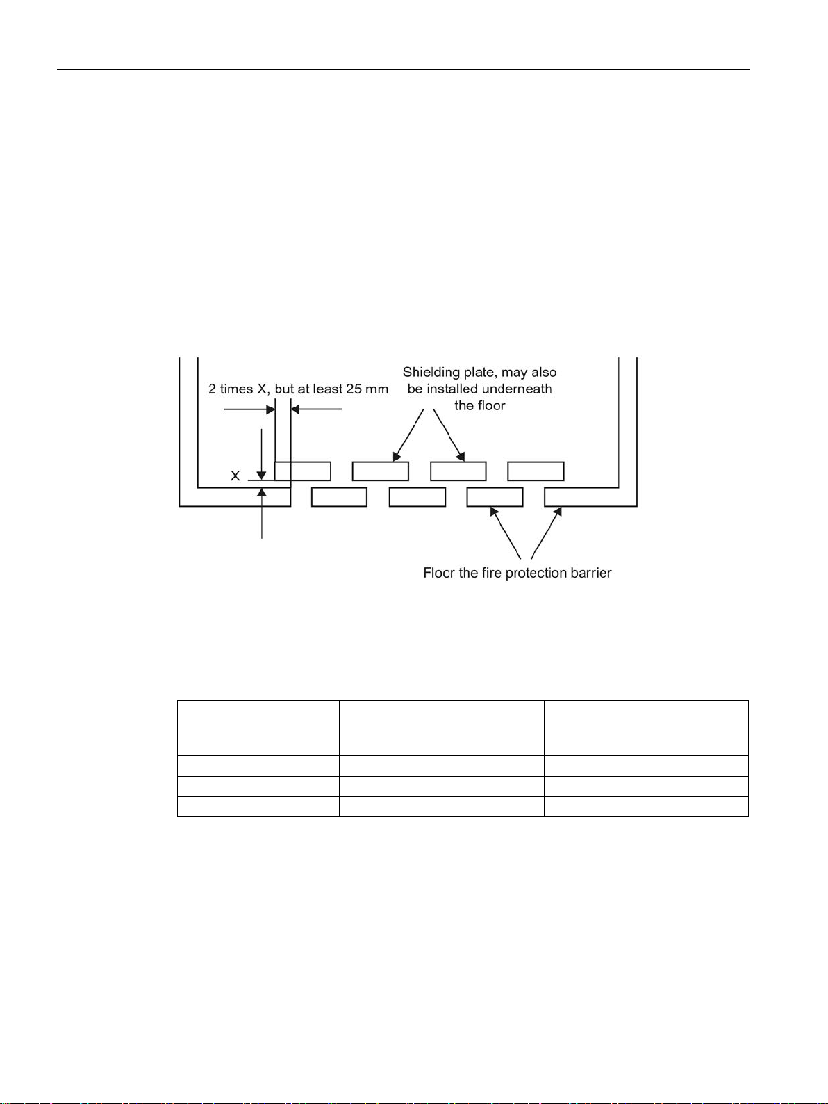
1.9 Fire protection
As output power exceeds the limit of circuitry with power limiting to IEC 61010-1 /
IEC 61131-2, malfunction of a SIMATIC TDC component may pose the risk of fire according
to IEC 61010-1 / IEC 61131-2. In order to prevent spreading of fire, suitable measures must
be taken to prevent ignition of adjacent parts or components as a result of burning parts that
possibly drop out of a component.
Two examples of a fire protection barrier to IEC 61010-1
Accepted perforation of a metal panel
Minimum thickness [mm] Maximum diameter of the holes
Minimum hole pitch, center-center
SIMATIC TDC hardware
18 System Manual, 08/2017, A5E01114865-AL
Page 19
Installation and EMC guidelines
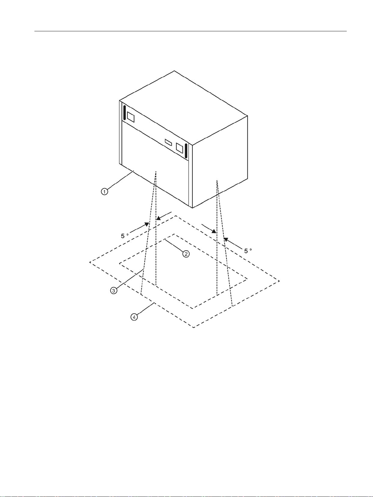
Minimum size of the fire protection barrier
①
Rack
②
Vertical projection of the rack
③
+50 from the vertical projection profile
④
Minimum size of the barrier
Aotewell Ltd
www.aotewell.com
Industry Automation
HongKong|UK|China
+86-755-8660-6182
1.9 Fire protection
SIMATIC TDC hardware
System Manual, 08/2017, A5E01114865-AL
19
Page 20

Installation and EMC guidelines
1.10
Control cabinet
Aotewell Ltd
www.aotewell.com
Industry Automation
HongKong|UK|China
+86-755-8660-6182
1.10 Control cabinet
● All control cabinets must be equipped with a grounding/equipotential busbar that must be
connected directly to the cabinet frame at both ends.
● It is not allowed to operate contactors without protective circuit in a control cabinet
containing SIMATIC TDC components.
● If contactors without protective circuit are operated in a control cabinet next to the
SIMATIC TDC cabinet, the cabinets must be partitioned by means of a sheet steel panel.
● All control cabinets in which SIMATIC TDC components are operated must be equipped
with a shielding busbar that must be connected directly at both ends to the cabinet frame.
● It is not allowed to use gas discharge lamps in the cabinet.
● The cabinet must be designed to enable unobstructed air convection.
SIMATIC TDC hardware
20 System Manual, 08/2017, A5E01114865-AL
Page 21
Installation and EMC guidelines
Arrangement and clearances
Aotewell Ltd
www.aotewell.com
Industry Automation
HongKong|UK|China
+86-755-8660-6182
1.10 Control cabinet
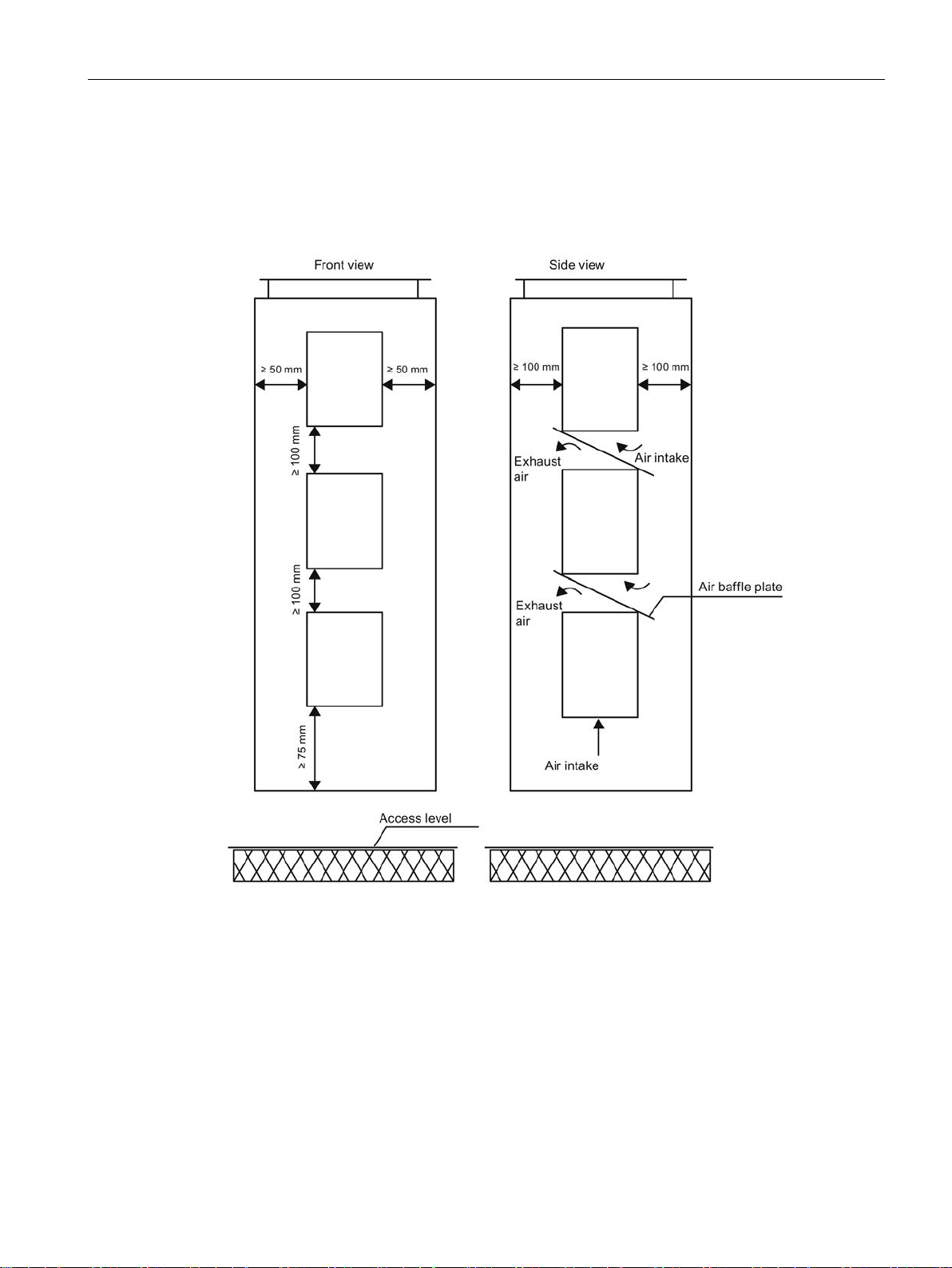
The following minimum dimensions must be maintained for stacked installations of
SIMATIC TDC racks:
e.g. control cabinet 2200 x 600 x 600 mm
SIMATIC TDC hardware
System Manual, 08/2017, A5E01114865-AL
21
Page 22
Installation and EMC guidelines
1.11
Equipotential bonding
Principle of the connection
Equipotential busbar
Aotewell Ltd
www.aotewell.com
Industry Automation
HongKong|UK|China
+86-755-8660-6182
1.11 Equipotential bonding
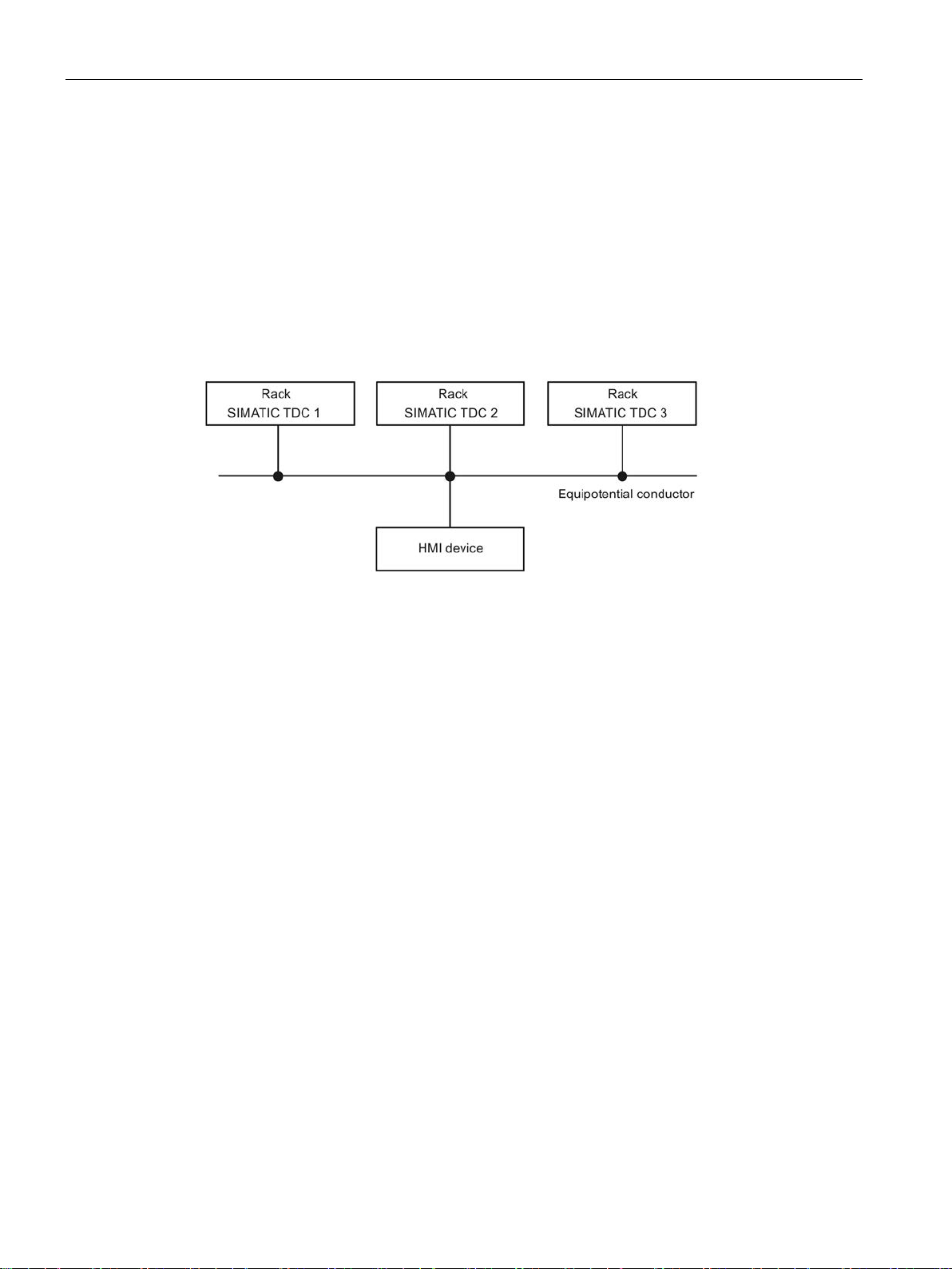
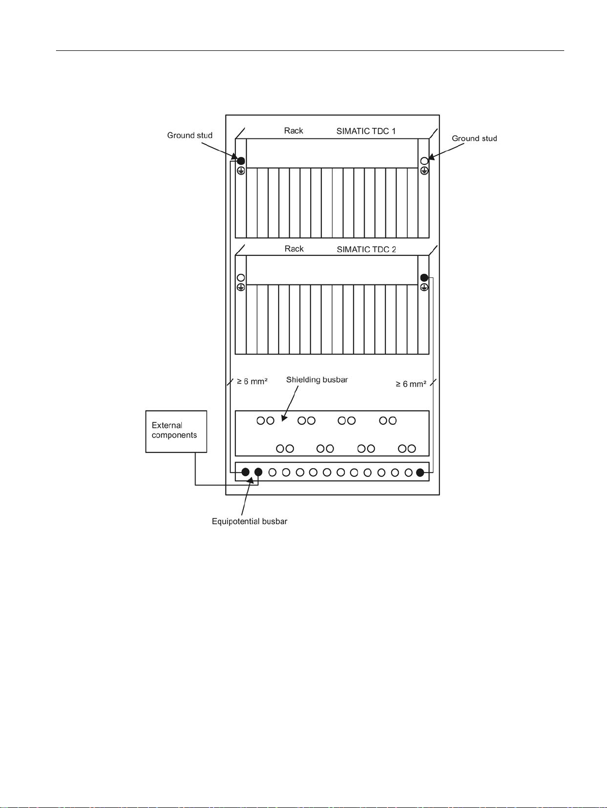
In order to ensure disturbance-free operation, the networked components may not develop
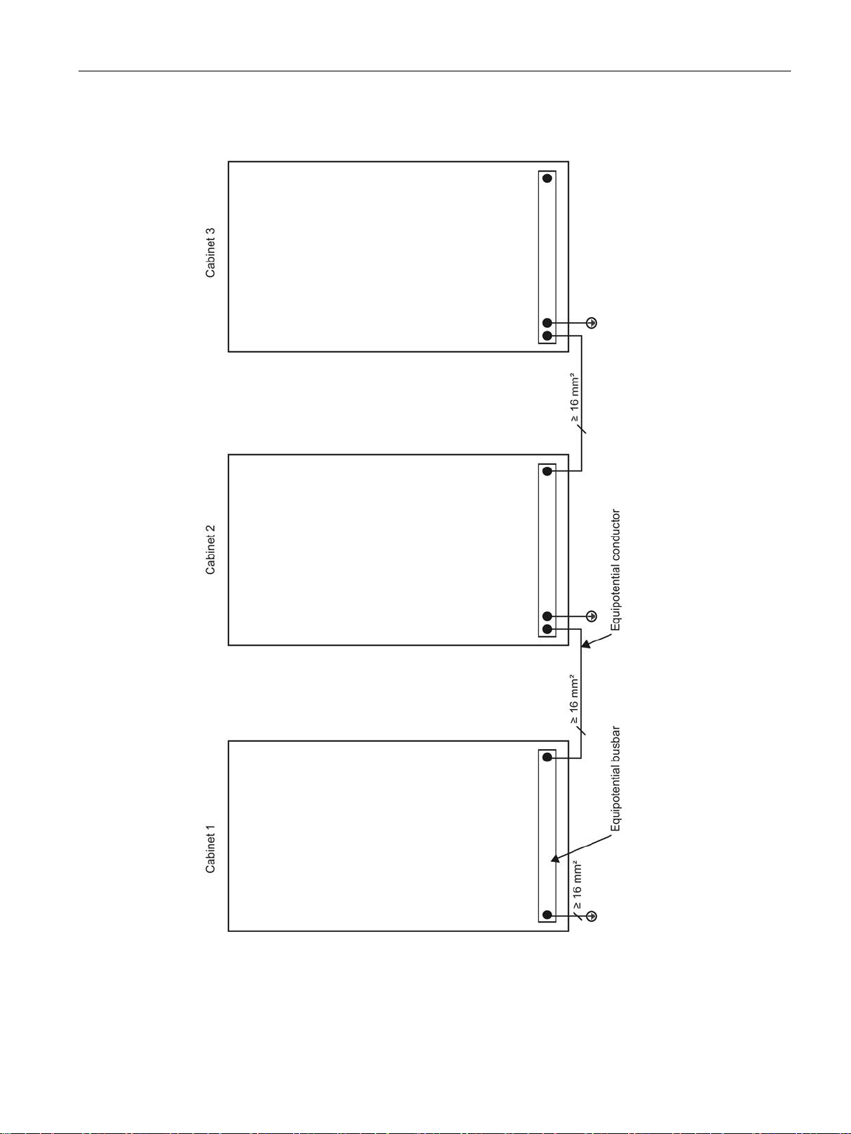
different potentials. For this reason, all components must be interconnected by means of
equipotential bonding with a minimum cross-section of 16 mm
All components (racks, power supplies, etc.) that are connected by signal cables must also
be interconnected by means of equipotential bonding (exception: components with fiber-optic
connections).
2
.
An equipotential busbar should be provided in each control cabinet to facilitate wiring.
All internal and external components must be interconnected with this equipotential busbar.
SIMATIC TDC hardware
22 System Manual, 08/2017, A5E01114865-AL
Page 23
Installation and EMC guidelines
Schematic circuit diagram
Aotewell Ltd
www.aotewell.com
Industry Automation
HongKong|UK|China
+86-755-8660-6182
1.11 Equipotential bonding
SIMATIC TDC hardware
System Manual, 08/2017, A5E01114865-AL
23
Page 24
Installation and EMC guidelines
Practical application examples
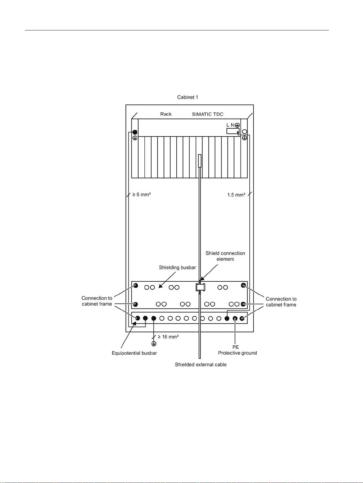
Termination of an external shielded cable
Aotewell Ltd
www.aotewell.com
Industry Automation
HongKong|UK|China
+86-755-8660-6182
1.11 Equipotential bonding
The shield must be connected to the shielding bus.
SIMATIC TDC hardware
24 System Manual, 08/2017, A5E01114865-AL
Page 25
Installation and EMC guidelines
Termination of an external shielded cable with supply via interface module
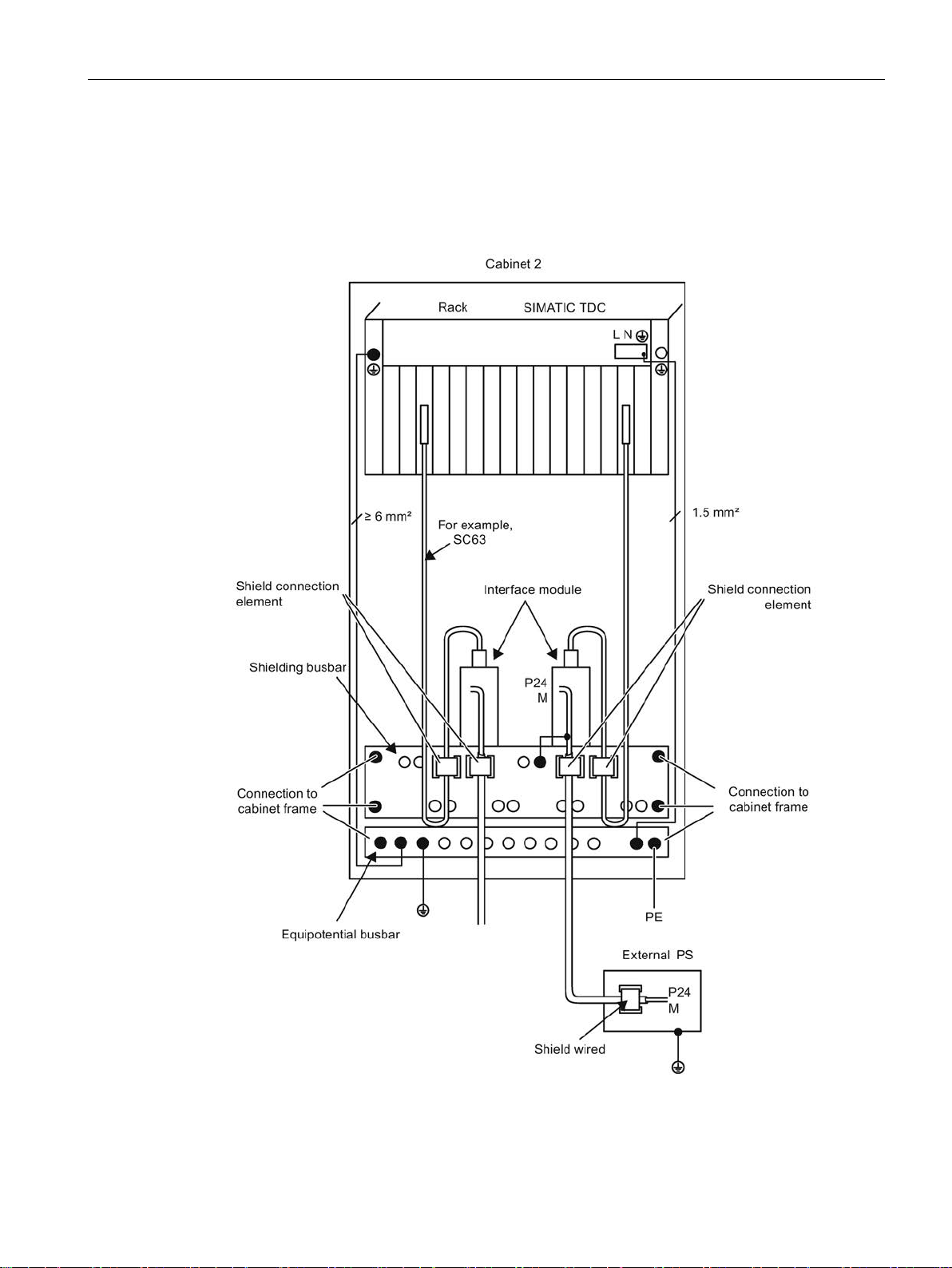
Aotewell Ltd
www.aotewell.com
Industry Automation
HongKong|UK|China
+86-755-8660-6182
1.11 Equipotential bonding
The shield must be connected to the shielding bus.
Ground of the external power supply must be wired to the shielding busbar, or to the
equipotential busbar.
SIMATIC TDC hardware
System Manual, 08/2017, A5E01114865-AL
25
Page 26
Installation and EMC guidelines
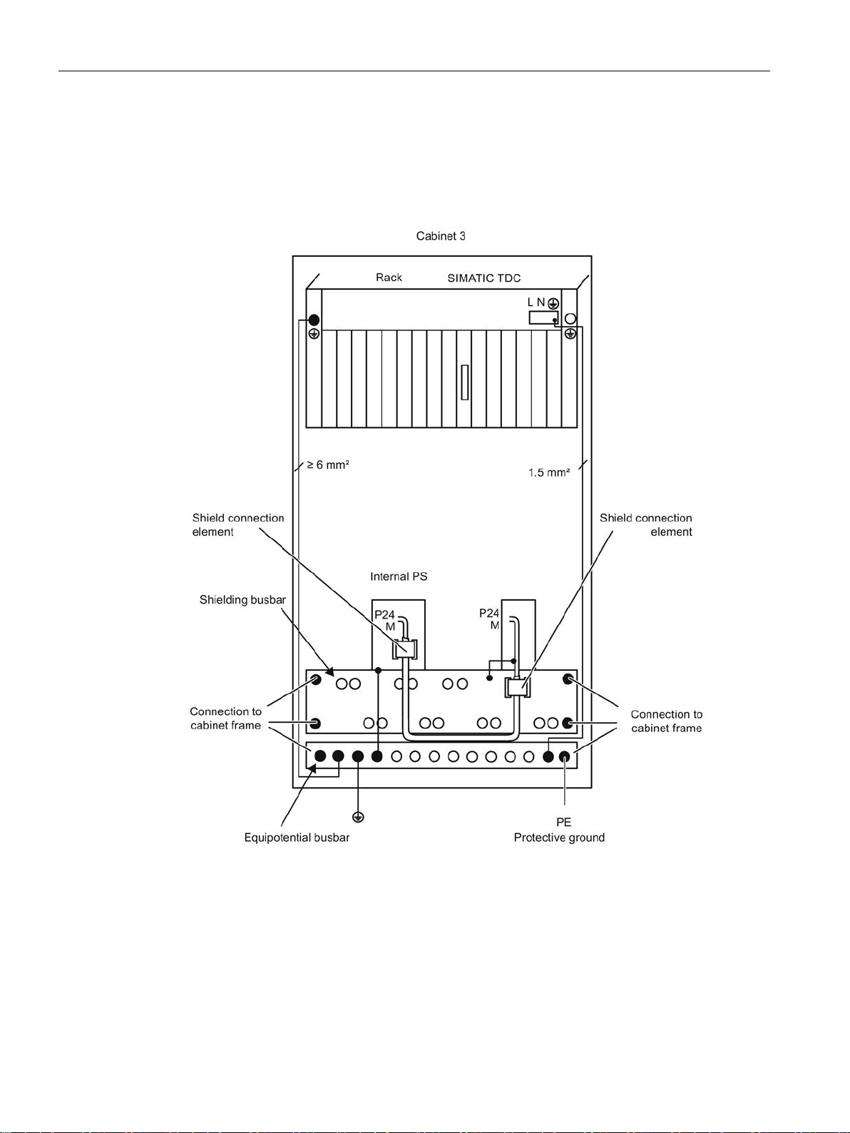
Termination of an internal power supply via interface module
Aotewell Ltd
www.aotewell.com
Industry Automation
HongKong|UK|China
+86-755-8660-6182
1.11 Equipotential bonding
The shield must be connected to the shielding bus.
Ground of the internal power supply must be connected to the shielding busbar, or to the
equipotential busbar.
SIMATIC TDC hardware
26 System Manual, 08/2017, A5E01114865-AL
Page 27
Installation and EMC guidelines
Example of grounding and potential equalization
Aotewell Ltd
www.aotewell.com
Industry Automation
HongKong|UK|China
+86-755-8660-6182
1.12 Protective ground
SIMATIC TDC hardware
System Manual, 08/2017, A5E01114865-AL
27
Page 28

Installation and EMC guidelines
1.12
Protective ground
Aotewell Ltd
www.aotewell.com
Industry Automation
HongKong|UK|China
+86-755-8660-6182
1.12 Protective ground
Protective ground is bonded to the cabinets or components via PE conductor. It is required in
SIMATIC TDC for safe operation and as interference suppression measure.
The protective conductor must be routed and dimensioned in accordance with IEC 61131-2
(11.9).
SIMATIC TDC hardware
28 System Manual, 08/2017, A5E01114865-AL
Page 29
Installation and EMC guidelines
1.13
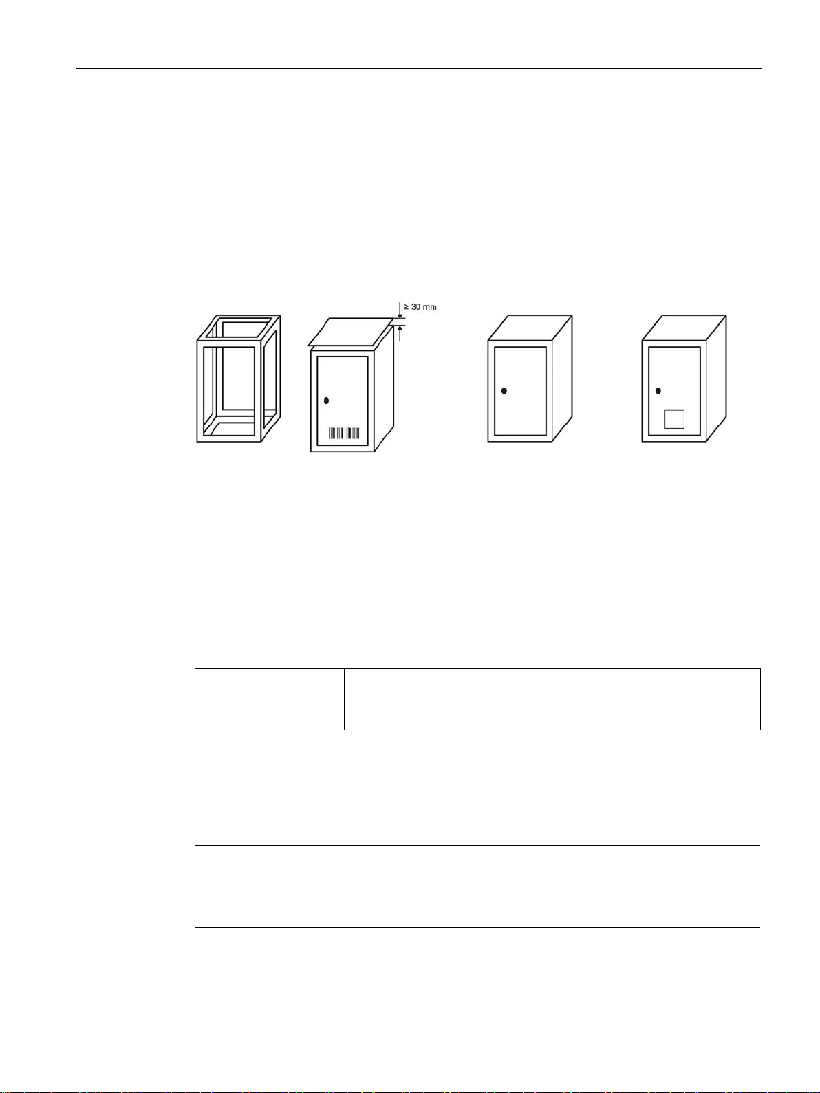
Power losses in the control cabinet
Built-in versions
1)
2)
3)
4)
Frame / panel
Control cabinet (open) with
open
Air vents > 600 cm²
Cabinet (closed) with
intrinsic convection and
forced convection
Closed cabinet with
heat e
SHUTDOWN MODE
Shutdown mode
ONE / ON
Shutdown is initiated upon the failure of one fan
Note
In the SHUTDOWN MODE, the internal output voltages of the rack are switched off. External
voltages connected to the module input must be switched off simultaneously (refer to section
Machinery directive
Aotewell Ltd
www.aotewell.com
Industry Automation
HongKong|UK|China
+86-755-8660-6182
1.13 Power losses in the control cabinet
The dissipation capability of a cabinet and therefore the air intake temperature of the rack
depends on the type of cabinet, on the ambient temperatures and on the internal
arrangement of the devices.
For installation variants 1) and 2), it is presumed that there is a clearance of at least 1 meter
between the top of the control cabinet and the building's ceiling.
Using the SHUTDOWN MODE switch the user can select whether to shut down the rack
immediately on failure of the first fan, or not until an additional fan failure.
TWO / OFF Shutdown is initiated upon the failure of one or more fans
For additional rack-specific information see:
UR6021 (6DD1682-0CH3) Control and display elements (Page 41)
UR5213 (6DD1682-0CH2)
UR5213 (6DD1682-0CH0)
-circuit ventilation
Control and display elements (Page 55)
Control and display elements (Page 67)
xchanger
(Page 17)).
SIMATIC TDC hardware
System Manual, 08/2017, A5E01114865-AL
29
Page 30

Installation and EMC guidelines
Air intake temperature
Shutdown mode
Maximum air intake temperature up to 2000 m above
sea level
Shutdown on fan failure
1.14
Power supply
Measures against disturbance voltages
Interference suppression on mains
24 V power supply
NOTICE
Network devices
Aotewell Ltd
www.aotewell.com
Industry Automation
HongKong|UK|China
+86-755-8660-6182
1.14 Power supply
The maximum air intake temperature on the SIMATIC TDC may not be exceeded. The
following limits are valid, depending on the "shutdown mode" switch setting.
ONE / ON
TWO / OFF
Shutdown on failure of two fans
The following notes related to the EMI/EMC measures to take for systems/plants should be
observed in order to avoid disturbance peaks on the supply cables in the cabinet:
The power supply of the rack already has a line filter with sufficient attenuation (refer to
"Manufacturers declaration").
For more demanding applications, you can install an additional line filter (e.g. 250 V AC /
10 A) or overvoltage arrester in the mains line, as close as possible to the cable entry on the
cabinet. Ground of the line filter/arrester must be wired to the equipotential busbar of the
cabinet using the shortest possible conductor length.
60° Centigrade
35° Centigrade
To attenuate external interference, a line filter must be provided for the 24 V power supply of
the digital I/O (e.g. SIFI-B line filter, Order No. B84112-B-.... from Epcos/NF 1-1 line filter of
Phoenix Contact). This filter should be installed as close as possible to the terminal block.
The shield connections of the line filter must be bonded to ground across the shortest
possible distance.
The 24 V power supply must also be equipped with lightning/overvoltage protection.
For more information, refer to the installation manual "SIMATIC Automation Systems
S7-400, Hardware and Installation
(http://support.automation.siemens.com/WW/view/de/1117849/0/en)".
Safe electrical isolation to IEC 61131-2 IEC 61131-2 (11.1.2.1.3) must be ensured for all
power supply units operated on SIMATIC TDC devices and modules.
SIMATIC TDC hardware
30 System Manual, 08/2017, A5E01114865-AL
Page 31
Installation and EMC guidelines
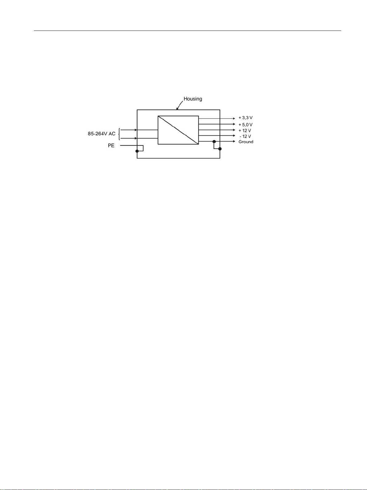
Potentials of power supply
Aotewell Ltd
www.aotewell.com
Industry Automation
HongKong|UK|China
+86-755-8660-6182
1.14 Power supply
In SIMATIC TDC, the ground connections of all secondary voltages are grouped and bonded
to the rack enclosure in order to improve the signal to interference ratio and to ensure proper
grounding.
SIMATIC TDC hardware
System Manual, 08/2017, A5E01114865-AL
31
Page 32

Installation and EMC guidelines
1.15
Rack
Note
The modules may not
Memory sub
As a matte
front connectors on the live component.
For module
1.16
Cables
All signal cables
Serial signal lines
power cable
Power supply cables
External power supply ground
Cables on system side
between signal lines and power
cables
Aotewell Ltd
www.aotewell.com
Industry Automation
HongKong|UK|China
+86-755-8660-6182
1.15 Rack
● The rack must be bonded to the grounding/equipotential busbar using the shortest
possible conductor with a minimum cross-section of 16 mm
bonding (Page 22).
● All modules and front panels must be screwed onto the rack. This rule also applies to
commissioning phase!
● Unused slots must be provided with SIMATIC TDC dummy front panels type SR 51 6DD
1682-0DA1.
● The connectors must be screwed/interlocked to the front panel.
● The limit of the air intake temperature may not be exceeded on the rack; refer to Control
cabinet (Page 20). The rack must be installed in a way that safely excludes heat
accumulation; refer toFire protection (Page 18).
● The air intake of the rack must be free of dust as far as possible. The air intake of the
rack (bottom) must be cleaned at cyclic intervals depending on the degree of soiling.
be inserted or removed while the rack is on live voltage. Exception:
-modules MC 5xx / MMCs.
r of principle it is not advisable to remove and insert memory sub-modules or
-specific notes, refer to the corresponding user documentation (hardware).
2
; refer to Equipotential
SIMATIC TDC hardware
32 System Manual, 08/2017, A5E01114865-AL
●
wired with strain relief.
●
housing, as well as to the shielding busbar. The cable shielding may not be wired to pin 1
of the connector.
● The
●
●
●
● A minimum clearance of > 10 cm must be maintained
operating voltage of the power cable used may not be less than the supply voltage.
power supply cable that is routed via interface module must be bonded to the shielding
busbar as specified in section "Connection via interfacee module".
"Equipotential bonding (Page 22)".
TDC should not be routed through the same cable duct.
of more than 1 kV.
you install must be shielded. All cables assembled by users must be
must be shielded. The shield must be bonded to a metalized connector
for the rack power supply does not require shielding. The permitted
for safety extra low voltages (e.g. 24 V DC) must be shielded. A
must be bonded to the equipotential busbar; refer to
and cables interconnecting the interface module with SIMATIC
carrying voltages less than 500 V and > 30 cm to power cables carrying voltages
Page 33
Installation and EMC guidelines
Design and temperature resistance
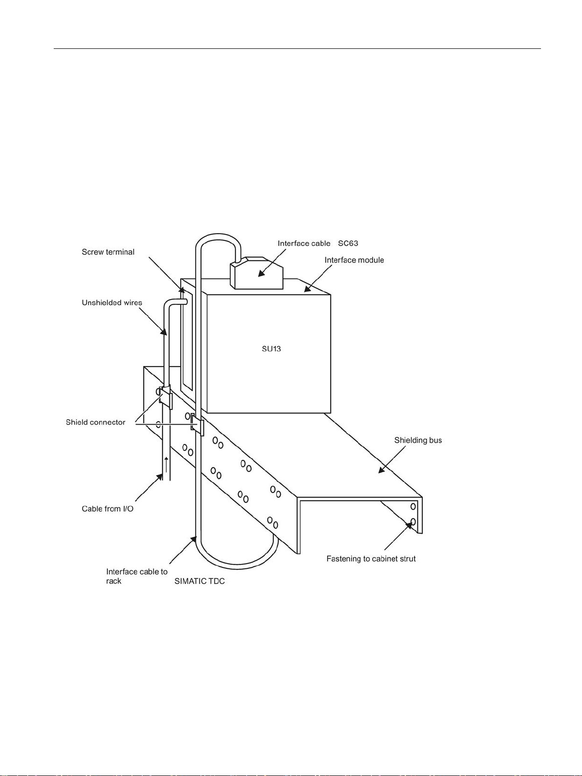
Connection via interface module
Aotewell Ltd
www.aotewell.com
Industry Automation
HongKong|UK|China
+86-755-8660-6182
1.16 Cables
All cables must be made of copper and be able to resist temperatures of up to at least 90 °C.
If interface modules are used, the shields of system-side cables and of routed the interface
module to SIMATIC TDC must be bonded to ground directly above or below the interface
module. Unshielded conductors that are terminated to screw terminals should be kept as
short as possible.
All lines should be kept as short as possible.
SIMATIC TDC hardware
System Manual, 08/2017, A5E01114865-AL
33
Page 34
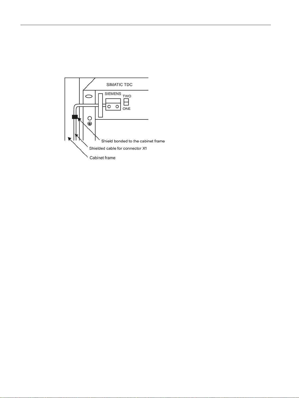
Installation and EMC guidelines
Connector X1 (UR6021 6DD1682-0CH3 and UR5213 6DD1682-0CH2)
Aotewell Ltd
www.aotewell.com
Industry Automation
HongKong|UK|China
+86-755-8660-6182
1.16 Cables
The cable wired to connector X1 on the rack must be shielded. The shield should be
terminated as close as possible to connector X1. You can connect conductor cross-sections
from 0.5 mm
Comment: We recommend using ferrules when using flexible cables.
2
to 1.5 mm2.
SIMATIC TDC hardware
34 System Manual, 08/2017, A5E01114865-AL
Page 35

Installation and EMC guidelines
1.17
ESD Directives
ESD
Handling ESD modules
Aotewell Ltd
www.aotewell.com
Industry Automation
HongKong|UK|China
+86-755-8660-6182
1.17 ESD Directives
Almost all of the SIMATIC TDC modules contain highly integrated components. Due to their
technology, these components are highly sensitive to overvoltage and, therefore, to ESD.
The abbreviation stands for electrostatic discharge
Modules equipped with such components are identified by the following warning label on
component side:
Electrostatic sensitive components can be destroyed by voltages and power levels far below
human perception. Components or modules are possibly exposed to such voltages when
touched by humans who have not been not electrostatically discharged. Following such
voltage peaks, it is usually impossible to identify malfunction of the component immediately,
as it needs an extended operating time before such malfunctions are disclosed.
● As a matter of principle, you should never touch electronic modules unless this is
unavoidable in the course of work to be carried out on the component.
● Do not touch components unless
– you are continuously grounded by means of an ESD bracelet, or
– or by wearing ESD shoes, or ESD shoe grounding strips.
● Always discharge your body before you touch an electronic module. This can be done
quite simply by touching a conductive, grounded object immediately before you handle
the component (e.g. bright metal parts of the control cabinet, water pipe etc.)
● Modules may not come into contact with highly insulating materials that are subject to
electrostatic charge, e.g. plastic foils, insulating table plates, clothing made of artificial
fiber.
● Modules must always be placed onto conductive surfaces (table with ESD mat,
conductive ESD foam rubber, ESD packaging bags, ESD transport containers, cardboard
or paper mats).
● Modules may not be brought close to data terminals, monitors, or television sets.
SIMATIC TDC hardware
System Manual, 08/2017, A5E01114865-AL
35
Page 36

Installation and EMC guidelines
Measuring and modifying ESD modules
Shipping modules
a
Conductive flooring
d
ESD coat
b
ESD tables = ESD chain
c
ESD shoes
f
Ground connection of the cabinets
e
ESD bracelet
Aotewell Ltd
www.aotewell.com
Industry Automation
HongKong|UK|China
+86-755-8660-6182
1.17 ESD Directives
● Measurements may only be taken on the modules when
– The measuring devices is grounded (e.g. via PE conductor), or
– The measuring head has been briefly discharged (e.g. by touching a bright metal part
of the control enclosure) prior to measurement with an electrically isolated measuring
device.
Always use ESD soldering irons for soldering work on modules, or at least grounded
soldering tips.
Modules and components must always be stored and shipped in conductive packing
materials (e. g. metalized plastic boxes, metal containers).
If using non-conductive packaging, you must protect the modules with a wrapping of made of
conductive material, e.g. conductive foam rubber, or household aluminum foil.
The following figure once again emphasizes the necessary ESD protective measures.
SIMATIC TDC hardware
36 System Manual, 08/2017, A5E01114865-AL
Page 37

2
2.1
Climatic conditions
Storage and transport conditions
IEC 60721 Part 3-2 Class 2K1, without condensation
Storage temperature
-40 °C to +70 °C
protected
refer to "Power losses in the control cabinet (Page 29)"
Operation
1080 to 795 hPa (corresponds to -1000 m to +2000 m)
3S2 (without sand in air)
2.2
Electrical protection and safety requirements
Safety regulations
IEC 61131-2
Protection class
Protection class I (with PE/ground conductor)
cles and water
2.3
External supply of the SIMATIC TDC modules (digital outputs)
Aotewell Ltd
www.aotewell.com
Industry Automation
HongKong|UK|China
+86-755-8660-6182
Table 2- 1
Operating conditions IEC 60721 Part 3-3 Class 3K3, stationary use, weather-
Operating temperatures
(air intake temperature)
Atmospheric pressure
Storage
Pollutant stress
Gases posing the risk of malfunction
Dust posing the risk of malfunction
Protection against the ingress of foreign parti-
IP 20
0 °C to + 60 °C; shutdown mode ONE
0 °C to + 35 °C; shutdown mode TWO
1080 to 660 hPa (corresponds to -1000 m to +3500 m)
ISA-S71.04 severity level G3
10 cm3/m3
SO
2
S 1 cm3/m3
H
2
Conditions of use according to IEC 60721, Part 3-3; Class
SIMATIC TDC hardware
System Manual, 08/2017, A5E01114865-AL
Safety extra low voltage (SELV/PELV circuit) to IEC 60364-4-41.
37
Page 38

General technical specifications
2.4
Mechanical requirements
Tested for
Test standard
Note
3 axes which are perpendicular to each other
three perpendicular axes
2.5
Electromagnetic requirements (industry)
Interference emission
EN 61000-6-4 : 2007 + A1:2011
Immunity to interference
EN 61000-6-2 : 2005
NOTICE
Using two-way radios and mobile telephones
TDC can
Aotewell Ltd
www.aotewell.com
Industry Automation
HongKong|UK|China
+86-755-8660-6182
2.4 Mechanical requirements
The following table provides information on the type and scope of checks regarding
mechanical ambient conditions.
Vibrations Vibration test according to
IEC 60068-2-6 (sine)
Shock Shock test according to
IEC 60068-2-27
Type of vibration: Frequency cycles with a rate of change of 1
octave/minute
10 Hz ≤ f ≤ 58 Hz, constant amplitude 0.075 mm
58 Hz ≤ f ≤ 150 Hz, constant acceleration 1 g
Duration of vibration: 10 frequency cycles per axis in each of the
Type of shock: half-sine
Strength of shock: 15 g peak value, 11 ms duration
Shock direction: 3 shocks each in +/– direction in each of the
The use of two-way radios and mobile phones in the immediate range of SIMATIC
influence the operation of the device.
SIMATIC TDC hardware
38 System Manual, 08/2017, A5E01114865-AL
Page 39

3
3.1
Rack UR6021 (6DD1682-0CH3)
3.1.1
Areas of application
See also
Aotewell Ltd
www.aotewell.com
Industry Automation
HongKong|UK|China
+86-755-8660-6182
Rack UR6021 with 21 slots forms the mechanical base for SIMATIC TDC
The system power supply is installed in the rear area of rack.
There is a fan tray in the upper part of the rack, which includes the monitoring and signaling
functions in addition to the fans.
The fan tray can be ordered as spare part (6DD1683-0CH3) and can be replaced by
qualified personnel.
A high-performance 64-bit backplane bus supports high-speed data exchange between the
inserted modules.
The CPU555 used in UR6021 supports P0 functionality.
For fast, direct communication between CPU555 modules, the rack UR6021 has a P0
connector in slots 01, 02, 03, 04, 09, 11, 13 and 15. Each CPU555 can communicate with up
to 7 additional CPU555 by means of the PCIe interface via the backplane bus (P0
connector). This means that a point-to-point connection always exists between any two
CPU555 modules.
Ventilation/cooling (Page 48)
SIMATIC TDC hardware
System Manual, 08/2017, A5E01114865-AL
39
Page 40
Rack
3.1.2
Mechanical layout
Fan tray (6DD1683-0CH3)
Aotewell Ltd
www.aotewell.com
Industry Automation
HongKong|UK|China
+86-755-8660-6182
3.1 Rack UR6021 (6DD1682-0CH3)
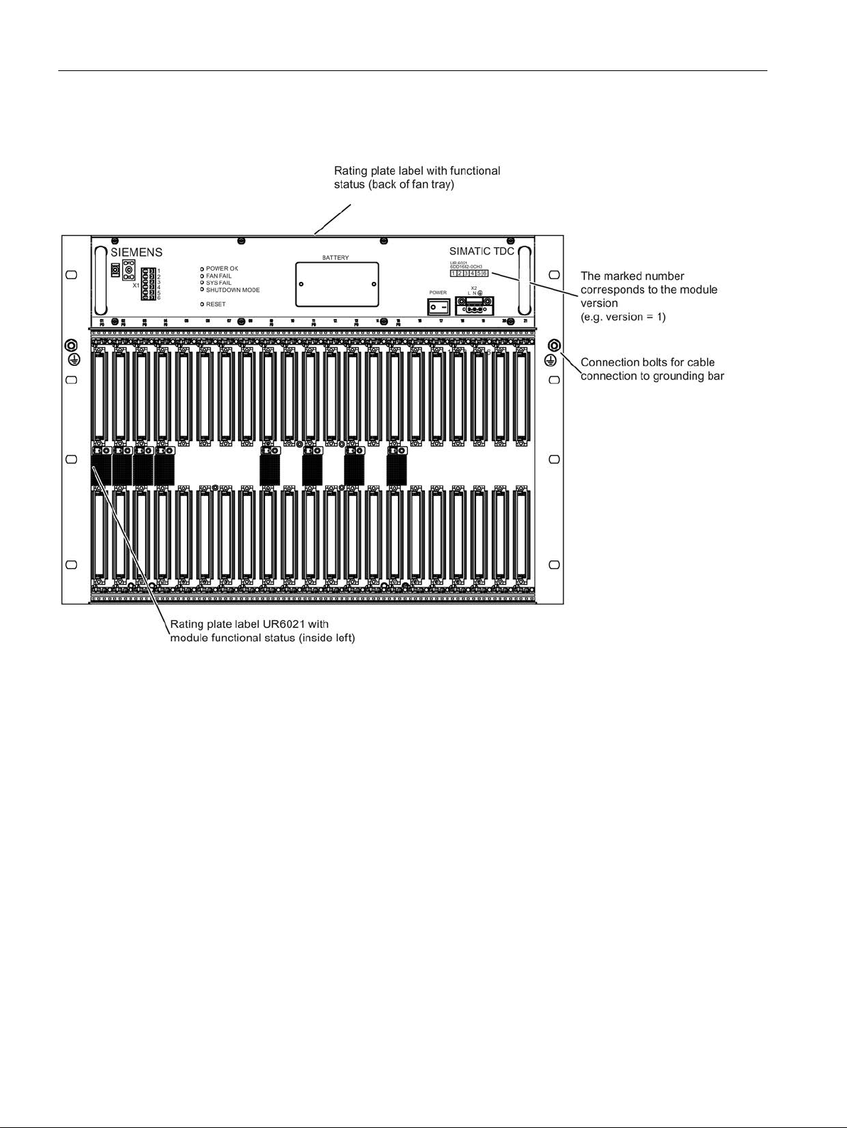
Figure 3-1 Rack UR6021 (front view)
The fan tray is inserted and screwed into the upper part of the rack. The fan tray contains six
fans and the control and monitoring functions for the rack.
SIMATIC TDC hardware
40 System Manual, 08/2017, A5E01114865-AL
Page 41
Rack
3.1.3
Control and display elements
X1
Note
Mixed assignment
Contacts consisting of combinations of safety extra
not permitted.
SHUTDOWN MODE
LED
RESET
BATTERY
X2
Aotewell Ltd
www.aotewell.com
Industry Automation
HongKong|UK|China
+86-755-8660-6182
3.1 Rack UR6021 (6DD1682-0CH3)
3 signaling relays, 230 V AC floating potential (3 x 2 contacts)
-low voltage and hazardous voltages are
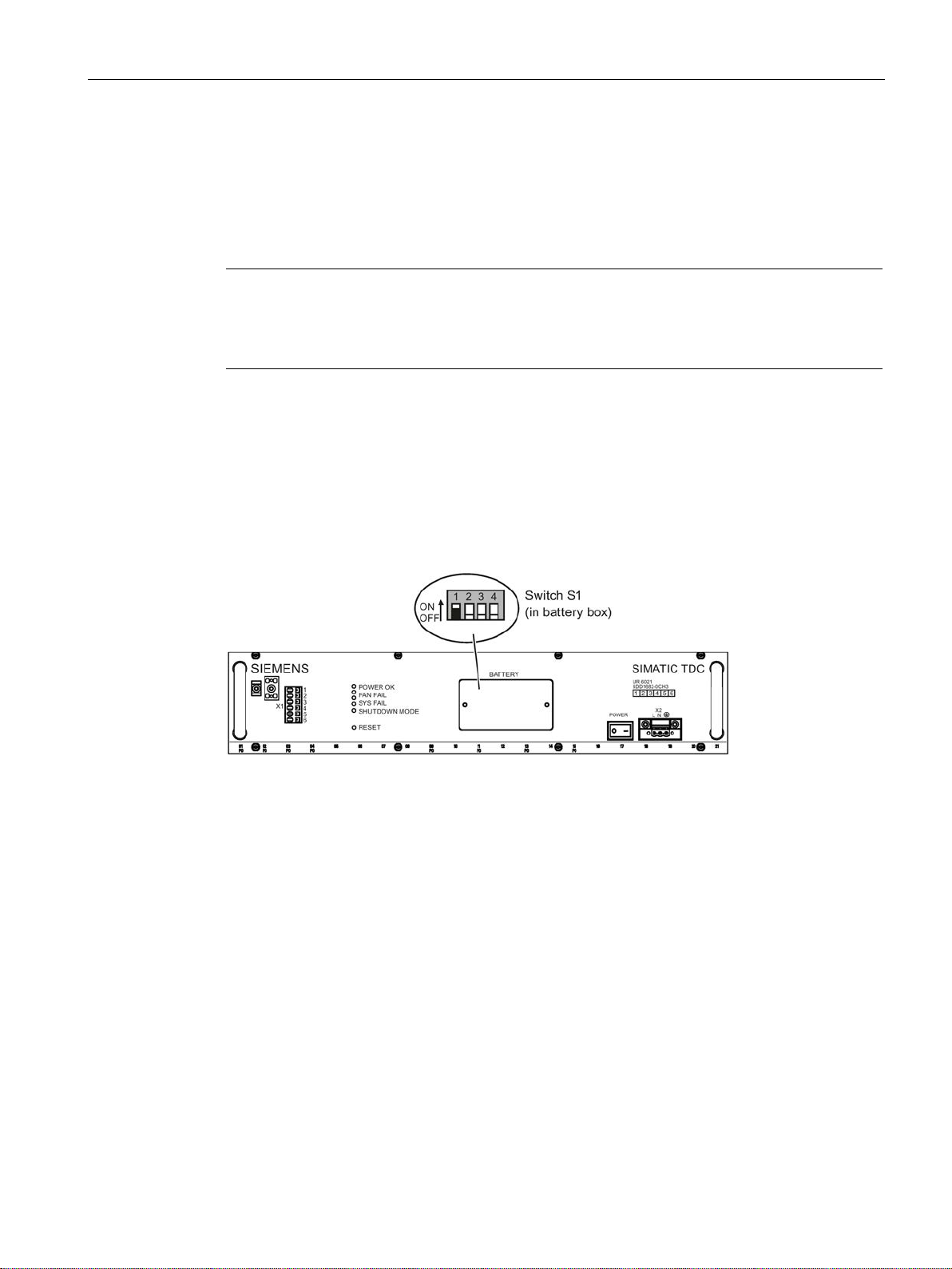
A system shutdown mode can be set in accordance with the switch position S1.1 (in the
battery compartment) as response to the failure of one or two fans.
● OFF = Shutdown on failure of two fans (SHUTDOWN MODE LED = on)
● ON = Shutdown on failure of one fan (SHUTDOWN MODE LED = flashes)
Figure 3-2 Front view of the fan tray
The four LEDs signal the operating state of the rack.
You can restart all modules by pressing the submerged pushbutton (rack RESET).
Backup battery compartment (1 x AA lithium battery)
Line voltage connection
SIMATIC TDC hardware
System Manual, 08/2017, A5E01114865-AL
41
Page 42

Rack
3.1.4
Status and fault displays
LED
Display
Rack state
POWER OK
green is on
fault-free operation
red is on
fault (refer to voltage monitoring)
FAN FAIL
Off
fault-free operation
On
fault (at least one fan has failed)
SYSFAIL
(red)
Off
fault-free operation
On
System was stopped
SHUTDOWN MODE
On
Shutdown on failure of two fans (corresponds to the OFF
position of switch S1.1)
tion of switch S1.1)
3.1.5
Power supply
Mains connection
Note
Always use the integrated strain relief for the mains cable on the 3
Input voltage
120/230 V AC
110/220 V DC
Test voltage
Primary ↔ PE
1500 V AC
Power consumption
800 W (apparent power approx. 835 VA)
Cable cross-section
3 x 1.5 mm2 (copper stranded wires dressed with wire end ferrules with ISO
ferrule)
Input current
In = 9 A
Is = < 40 A (inrush peak)
External fuse
The power supply is equipped with an internal 20 A fuse. This means that
Alternatively, a slow-acting fuse may be used.
Note
A mains disconnect unit must be provided during installation of the rack.
Aotewell Ltd
www.aotewell.com
Industry Automation
HongKong|UK|China
+86-755-8660-6182
3.1 Rack UR6021 (6DD1682-0CH3)
Table 3- 1 Status displays for UR6021
(green or red)
(red)
(yellow)
Flashes Shutdown on failure of one fan (corresponds to the ON posi-
Mains is connected to the 3-pin screw terminal block on the right side of the power supply
unit.
-pin screw terminal block.
The pin assignment is printed onto the front panel.
insulating collars; stripped length: 10-12 mm according to the used wire end
(dimensioning)
only the mains supply has to be fused.
It is recommended to use a standard 16 A thermo magnetic circuit-breaker
(B characteristic).
SIMATIC TDC hardware
42 System Manual, 08/2017, A5E01114865-AL
Page 43
Rack
3.1.6
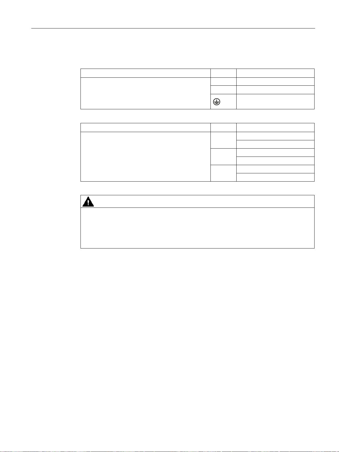
Wiring diagram
X2
Pin
Function
L
Line conductor
X1
Pin
Function
SYSFAIL signaling contact
NC contact
POWER signaling contact
NO contact
FAN FAIL signaling contact
NO contact
WARNING
PE terminal
Aotewell Ltd
www.aotewell.com
Industry Automation
HongKong|UK|China
+86-755-8660-6182
3.1 Rack UR6021 (6DD1682-0CH3)
Screw terminal with screw lock (3x1.5 mm2, stranded
wires dressed with wire end ferrules with insulating
collars)
Make sure that the strain relief is properly mounted.
N Neutral conductor
PE/ground conductor
Cage clamp terminal (0.5 mm2 –-1.5 mm2, stripped
length 7 mm, stranded wires dressed with wire end
ferrules with insulating collars)
Make sure that the strain relief is properly mounted.
1, 2
3, 4
5, 6
The PE/ground conductor must be connected to the power supply.
The PE/ground terminal on the rack (min. 6 mm
2
) is inappropriate.
The PE/ground conductor must be green with yellow stripe (green/yellow).
Ungrounded installation of the rack is not planned.
SIMATIC TDC hardware
System Manual, 08/2017, A5E01114865-AL
43
Page 44

Rack
3.1.7
Voltage monitoring
Input voltage
Input voltage
Reaction
ACFAIL
output voltages <85 V
Output voltage
Voltage monitoring functions at the power supply
outlet
Reaction
- 12 V in the range from -11 V to -13 V
System failure alarm
HW Config
SYSFAIL
Aotewell Ltd
www.aotewell.com
Industry Automation
HongKong|UK|China
+86-755-8660-6182
3.1 Rack UR6021 (6DD1682-0CH3)
The input voltage is monitored for low level.
Undervoltage < approx. 85 V
Voltage dips ≤ 20 ms are buffered.
The power supply unit and therefore the system are restarted automatically on recovery from
a voltage dip below the permissible mains voltage.
The power on/off sequence (e.g. generation of a RESET or SYSFAIL signal) corresponds to
the reaction to manual operation of the mains switch.
All output voltages are monitored (e.g. for overload/short-circuit).
+5 V in the range from 4.75 V to 5.35 V “POWER OK” LED is lit green;
+ 3.3 V in the range from +3.18 V to +3.5 V
+ 12 V in the range from +11 V to +13 V
In all other cases, the “POWER OK” LED is lit red.
signal and CPU STOP, shutdown of
Select the "Object properties" in the "STOP" tab of
the relevant module to a system failure alarm (bus signal *
● The other modules also change to STOP
● The other modules remain in RUN
SIMATIC TDC hardware
44 System Manual, 08/2017, A5E01114865-AL
to configure the response of
=low):
Page 45
Rack
3.1.8
Battery backup
Battery connection
Technical specifications of the battery
Backup battery
Article number
6ES7971-0BA00
Rated voltage
3.6 V
Rated capacity
2.3 Ah
WARNING
Handling lithium batteries
Aotewell Ltd
www.aotewell.com
Industry Automation
HongKong|UK|China
+86-755-8660-6182
3.1 Rack UR6021 (6DD1682-0CH3)
A backup battery must be installed in the battery box to enable the backup of configured
values on power failure (using SAV function blocks).
Type 1 x Lithium AA
You may only use batteries that have been approved by Siemens!
Risk of injury, damage to assets, and emission of pollutants. Improper handling of a Lithium
battery may cause its explosion and incorrect disposal of used lithium batteries may lead to
emission of pollutants. For these reasons, you should strictly observe the following notes:
• Do not throw new or waste batteries into an open fire, or perform any soldering work on
the cell body (max. temperature 100° C)
• Do not recharge waste batteries - risk of explosion!
• Do not open the battery.
• Always replace battery with one of the same type. Always order replacements from
Siemens.
This ensures that you are in possession of a short circuit-proof type.
• You should return waste batteries to the battery manufacturer, dispose of the batteries
as special waste at a recycling facility.
SIMATIC TDC hardware
System Manual, 08/2017, A5E01114865-AL
45
Page 46

Rack
Backup time
Battery voltage monitoring
Battery replacement
See also
Aotewell Ltd
www.aotewell.com
Industry Automation
HongKong|UK|China
+86-755-8660-6182
3.1 Rack UR6021 (6DD1682-0CH3)
Sample calculation:
Capacity of the backup battery: 2.3 Ah, 63 % is assumed for calculation.
Backup current: 200 µA (monitoring 20 µA + max. 180 µA for the slots, CPU555/CPU551
needs 3 µA)
Backup time = 2.3 Ah * 0.63 / 200 µA = 7245 h ≙ 300 days
This time is valid for a rack that is switched off. Only the battery monitoring function draws a
current of 20 µA while the rack is powered on.
It is recommended to replace the batteries at annual intervals. The backup function is
deactivated when the fan tray is removed.
The CPU module inserted in slot 1 detects missing or low backup batteries and signals these
states with a flashing "b".
Unscsrew and remove the lid of the battery compartment to remove the battery.
Observe correct polarity when inserting the battery. You should also take care not to bend
the connection tabs of the battery holder during replacement.
To prevent data loss, you should always replace the battery while the rack is powered on.
Ventilation/cooling (Page 48)
SIMATIC TDC hardware
46 System Manual, 08/2017, A5E01114865-AL
Page 47
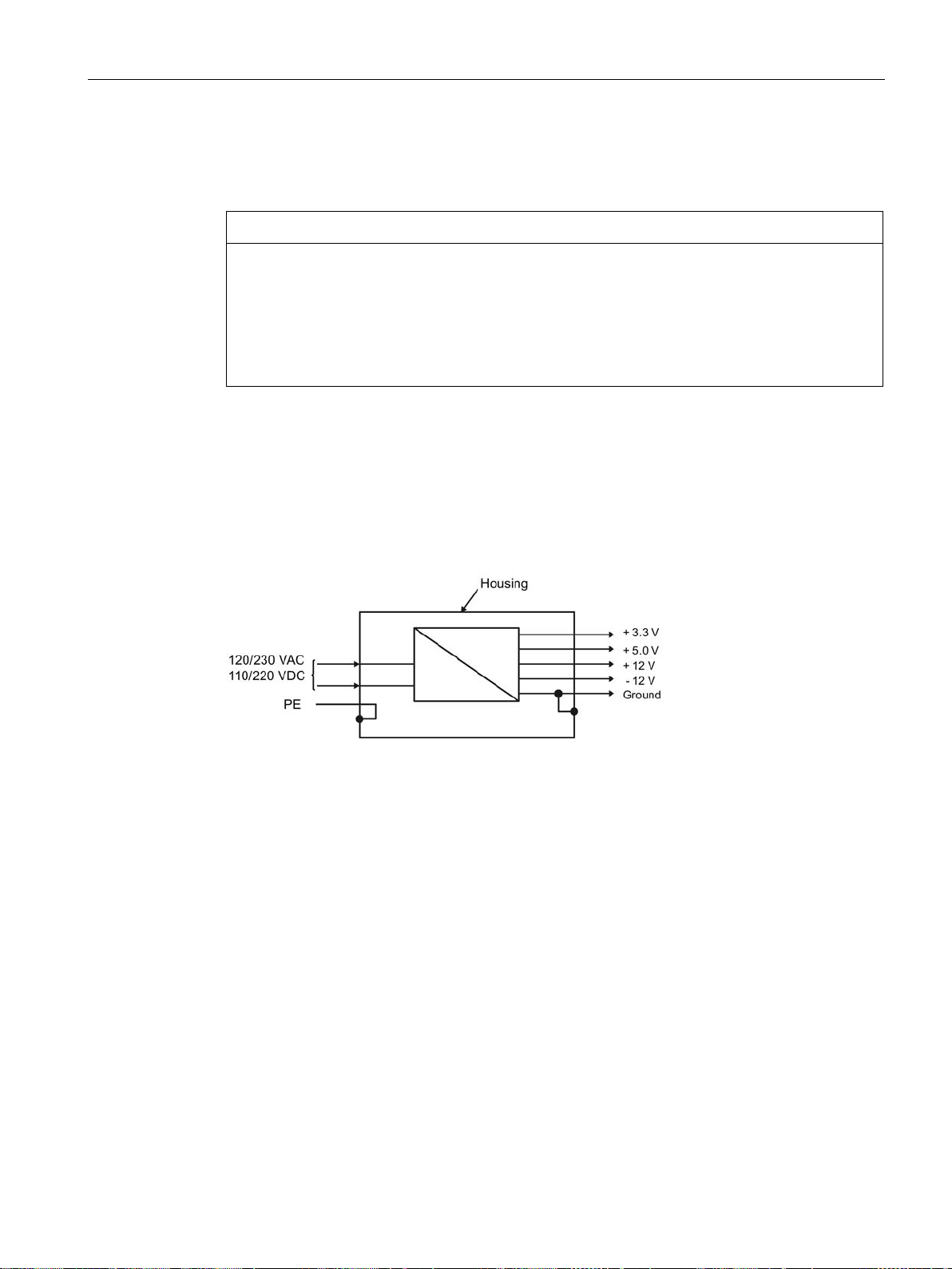
Rack
3.1.9
Modules
NOTICE
Damaging of the ESD braid
3.1.10
Power supply potentials
Aotewell Ltd
www.aotewell.com
Industry Automation
HongKong|UK|China
+86-755-8660-6182
3.1 Rack UR6021 (6DD1682-0CH3)
Make sure that the modules you insert are properly aligned in their relevant slot.
Do not push the modules towards the left when inserting these, because you would risk
damage to the ESD braid of the modules already inserted. Observe this particularly at slot
1, as a metal spring has been installed in this slot.
If the ESD braid or a metal spring is severely damaged, the module can no longer be used
because there is a risk of a short circuit with the potentials of a neighboring module.
In SIMATIC TDC, the ground connections of all secondary voltages are grouped and bonded
to the rack enclosure in order to improve the signal to interference ratio and to ensure proper
grounding.
SIMATIC TDC hardware
System Manual, 08/2017, A5E01114865-AL
47
Page 48

Rack
3.1.11
Ventilation/cooling
Note
For more information, refer to section "
Note
FANOPH
Using the FANOPH function block, you can read out the
from the first CPU555 and monitor it for a limit.
Fan monitor
NOTICE
Safe isolation from supply
NOTICE
ESD Directives
Aotewell Ltd
www.aotewell.com
Industry Automation
HongKong|UK|China
+86-755-8660-6182
3.1 Rack UR6021 (6DD1682-0CH3)
The rack is equipped with a fan tray with 6 fans for forced convection of the modules and the
system power supply.
Since the rack is not equipped with an air filter, you should provide a filter on the cabinet if
necessary.
Control cabinet (Page 20)".
operating hours counter of the fan
The fans are monitored (speed). Activation of the monitoring function is delayed in order to
enable the reliable startup of the rack after you switched on power.
On failure of one or two fans, the power supply is shut down depending on the operating
mode in order to prevent thermal destruction of the modules.
The operating mode (SHUTDOWN MODE) is selected using switch S1.1, which is integrated
in the power supply. The power supply is shut down if one fan has failed and switch position
"ON" is set, or if two fans have failed and switch position "OFF" is set.
Switch off power to the rack before you remove the screws of the battery compartment.
The battery compartment cover must be unscrewed to actuate switch S1.
Observe the corresponding ESD directives.
The operating mode setting is indicated by the "SHUTDOWN MODE" LED on the front
panel.
SIMATIC TDC hardware
48 System Manual, 08/2017, A5E01114865-AL
Page 49
Rack
NOTICE
Forced cooling
Replacing the fan tray
Fan try
Article number
6DD1683-0CH3
NOTICE
Replacing the fan tray
Aotewell Ltd
www.aotewell.com
Industry Automation
HongKong|UK|China
+86-755-8660-6182
3.1 Rack UR6021 (6DD1682-0CH3)
See section "Status and fault displays (Page 42)".
If the modules require forced cooling (e.g. CPU555), always set the "SHUTDOWN MODE"
slide switch S1.1 to "ON" for air intake temperatures from 0 °C to 60 °C.
You may only set the position of switch S1.1 to "OFF" if it can be ensured that the air intake
temperature at the rack does not exceed 50 °C.
The power supply is not shut down on failure of a single fan, but the corresponding
backplane bus signal (FANAL*) is activated and can be detected by the configuration
software.
The fan tray is can be ordered as a replacement part and be replaced.
Electrostatic sensitive components can be destroyed by voltages and power levels far below
human perception. Components or modules are possibly exposed to such voltages when
touched by humans who have not been not electrostatically discharged. Following such
voltage peaks, it is usually impossible to identify malfunction of the component immediately,
as it needs an extended operating time before such malfunctions are disclosed.
If the fan tray is damaged, it may not be installed.
Proceed as follows to replace the fan tray:
1. Make sure that the leads to X2 and possibly X1 are de-energized and secure them
against reconnection.
2. Ensure that adjacent live parts cannot be touched.
3. Remove the power connector X2.
4. If necessary, remove the wires to X1 (including the strain relief and shield connection).
5. Loosen the 8 screws on the top and bottom of the fan tray.
SIMATIC TDC hardware
System Manual, 08/2017, A5E01114865-AL
49
Page 50
Rack
CAUTION
Sharp-edged front panel
Signaling relay
NOTICE
Assignment of the contacts
Signaling relay
Terminal X1
Contact in switched off state
Contact in error-free op-
eration
LED in error-free operation
SYSFAIL
1.2
Closed
Closed
Off
POWER
3.4
Open
Closed
green is on
Aotewell Ltd
www.aotewell.com
Industry Automation
HongKong|UK|China
+86-755-8660-6182
3.1 Rack UR6021 (6DD1682-0CH3)
6. Pull the fan tray out of the rack by the handles.
The edges and corners of the front plate of the fan tray may cause injury. Use suitable
protective gloves to remove and install it.
7. Slide the new fan tray into the rack until it clicks and the faceplate is flush to the front
panel.
8. Fasten the fan tray (8 screws on the top and bottom of the fan tray).
9. Insert a new backup battery; see section "Battery backup (Page 45)".
10.If necessary, connect the wires to X1 (including the strain relief and shield connection).
11.Connect the power connector X2.
12.Switch on the power again.
Three 230 V signaling relays with floating potential facilitate external evaluation of the rack
system states.
Contacts consisting of combinations of safety extra-low voltage and hazardous voltages are
not permitted.
FAN FAIL 5.6 Open Closed Off
SIMATIC TDC hardware
50 System Manual, 08/2017, A5E01114865-AL
Page 51

Rack
3.1.12
Technical specifications
Article number
Rack UR6021
6DD1682-0CH3
General data
Degree of protection
IP 20
Protection class
Protection class 1 with PE/ground conductor
Operating temperatures
0 °C to +60 °C
Relative air humidity
5 % to 95 %, no condensation
Storage: 1080 hPa to 660 hPa
Power input
93.5 V DC to 253 V DC
Max. inrush current
< 40 A
Power factor
EN 61000-3-2
Pollution degree
2
Overvoltage category
II
Power failure backup
min. 20 ms
Aotewell Ltd
www.aotewell.com
Industry Automation
HongKong|UK|China
+86-755-8660-6182
3.1 Rack UR6021 (6DD1682-0CH3)
Safety EN 61131-2
Storage temperatures -40 °C to +70 °C
Atmospheric pressure Operation: 1080 hPa to 795 hPa
Rated input voltage
• Rated value
• 120 V AC to 230 V AC
• Permissible range
Rated input current
• At 120 V AC
• At 230 V AC
• At 110 V DC
• At 220 V DC
Line frequency
• Rated value (AC)
(DC)
• Permissible range
110 V DC to 220 V DC
• 85 V AC to 264 V AC (wide-range input)
• 6.7 A
• 3.5 A
• 7.3 A
• 3.7 A
• 50/60 Hz
(0 Hz)
• 47-63 Hz
SIMATIC TDC hardware
System Manual, 08/2017, A5E01114865-AL
51
Page 52

Rack
Output voltages of the power supply
Output current
Total
for the modules
+5 V
120 A
79 A
+3.3 V
60 A
36 A
-12 V
17 A
5 A
Note
Make sure that you do not exceed a total of 600 W (continuous load at 60 °C). This must be
ensured i your configuration.
The output currents of the individual modules are listed in the respective description.
do not
Battery
max. 180 µA for the slots 1-21
Relay contacts (X1)
Rated voltage (AC)
230 V (max. 264 V)
Rated current
2 A
NOTICE
Assignment of the contacts
Dimensions
Number of rack slots
21
Dimensions W x H x D [mm]
approx. 482.6 x 354.9 x 343
Weight
Approx. 20 kg
Aotewell Ltd
www.aotewell.com
Industry Automation
HongKong|UK|China
+86-755-8660-6182
3.1 Rack UR6021 (6DD1682-0CH3)
Rated output voltage
+12 V 17 A 5 A
All outputs are sustained short circuit-proof and
Current load Approx. 20 µA for the monitoring and
Contacts consisting of combinations of safety extra-low voltage and hazardous voltages are
not permitted.
need a basic load.
SIMATIC TDC hardware
52 System Manual, 08/2017, A5E01114865-AL
Page 53
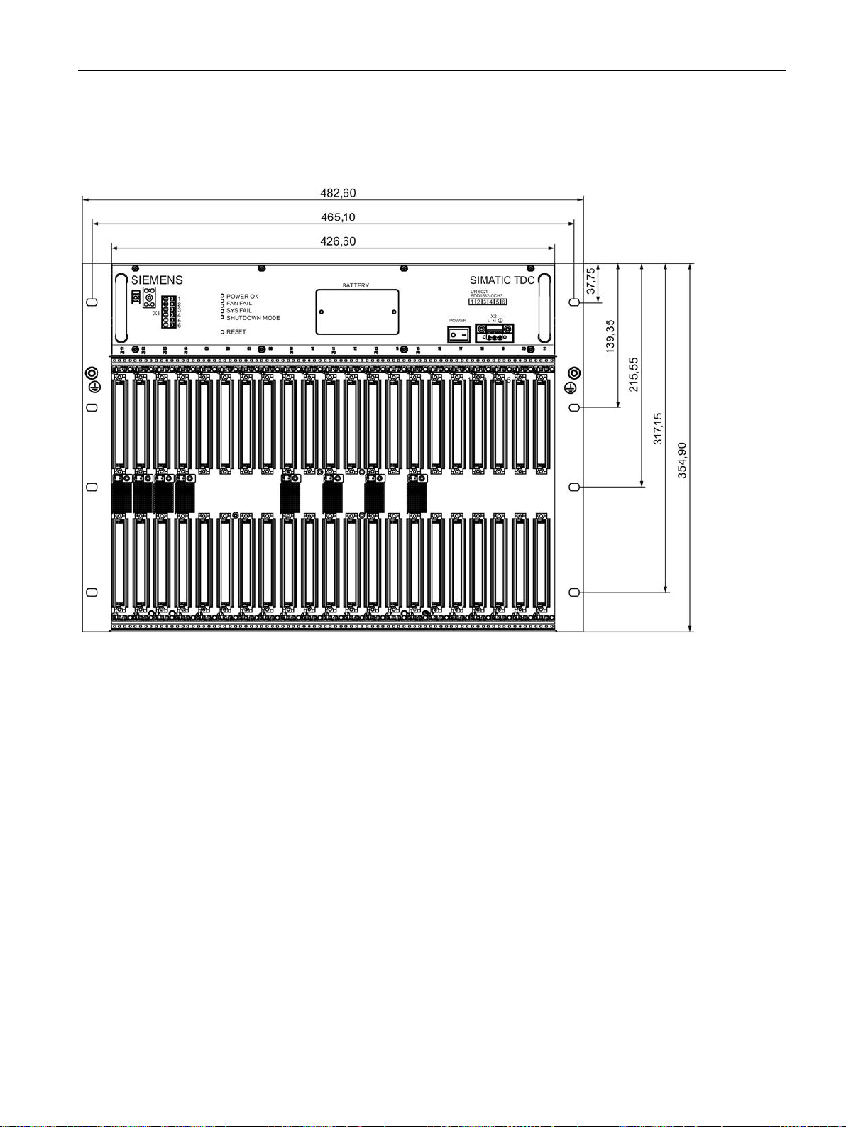
Rack
Dimensional drawing
Aotewell Ltd
www.aotewell.com
Industry Automation
HongKong|UK|China
+86-755-8660-6182
3.1 Rack UR6021 (6DD1682-0CH3)
Dimensions in mm
Figure 3-3 Dimension drawing of rack UR6021
SIMATIC TDC hardware
System Manual, 08/2017, A5E01114865-AL
53
Page 54
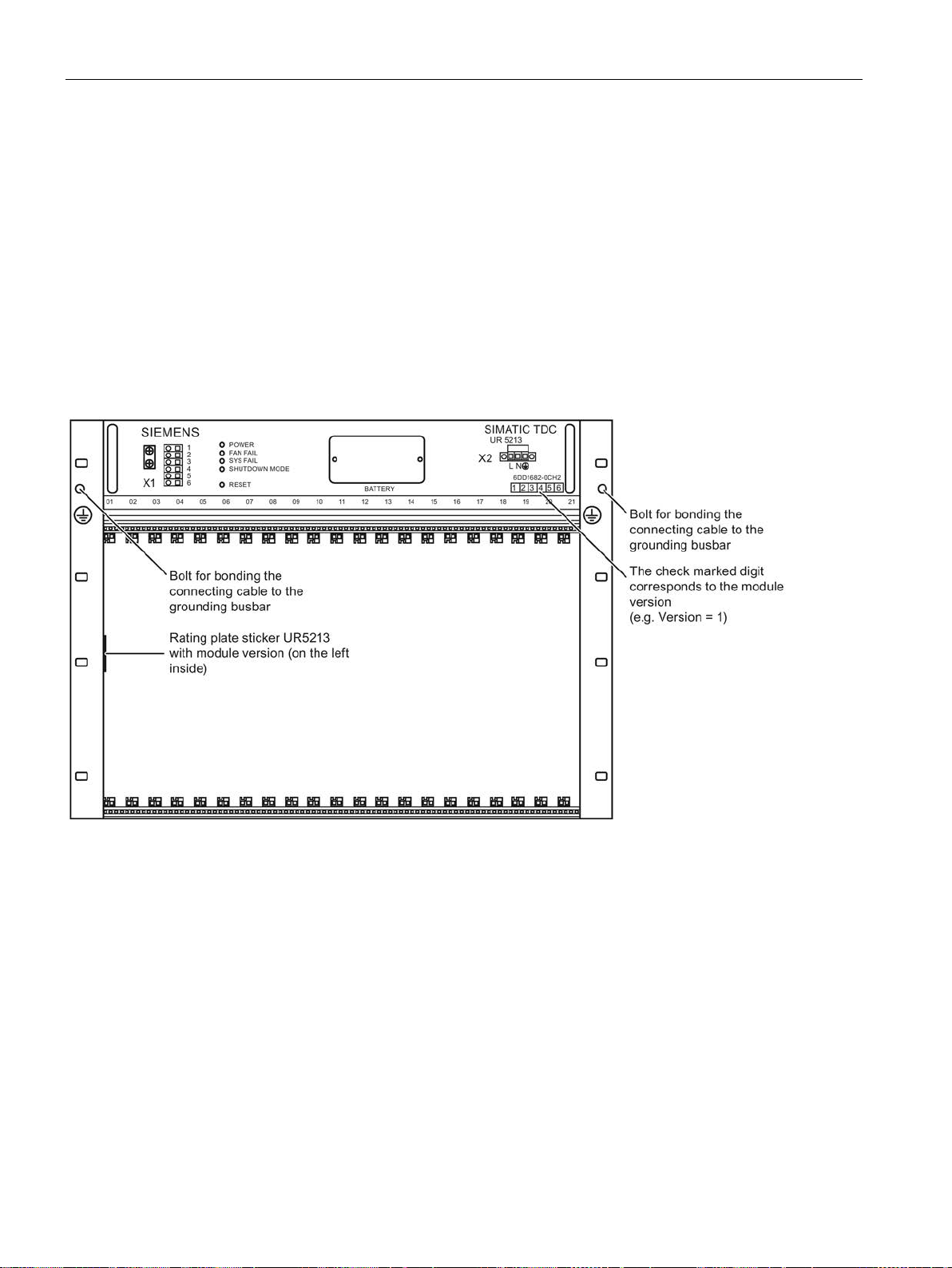
Rack
3.2
Rack UR5213 (6DD1682-0CH2)
3.2.1
Areas of application
3.2.2
Mechanical layout
Power supply
Aotewell Ltd
www.aotewell.com
Industry Automation
HongKong|UK|China
+86-755-8660-6182
3.2 Rack UR5213 (6DD1682-0CH2)
Rack UR5213 with 21 slots forms the mechanical base for SIMATIC TDC and features an
integrated system power supply and integrated system fans. A high-performance 64-bit
backplane bus supports high-speed data exchange between the inserted modules.
Figure 3-4 Rack UR5213 (front view)
The power supply with integrated fan for forced convection is installed in the rear section of
the rack.
SIMATIC TDC hardware
54 System Manual, 08/2017, A5E01114865-AL
Page 55
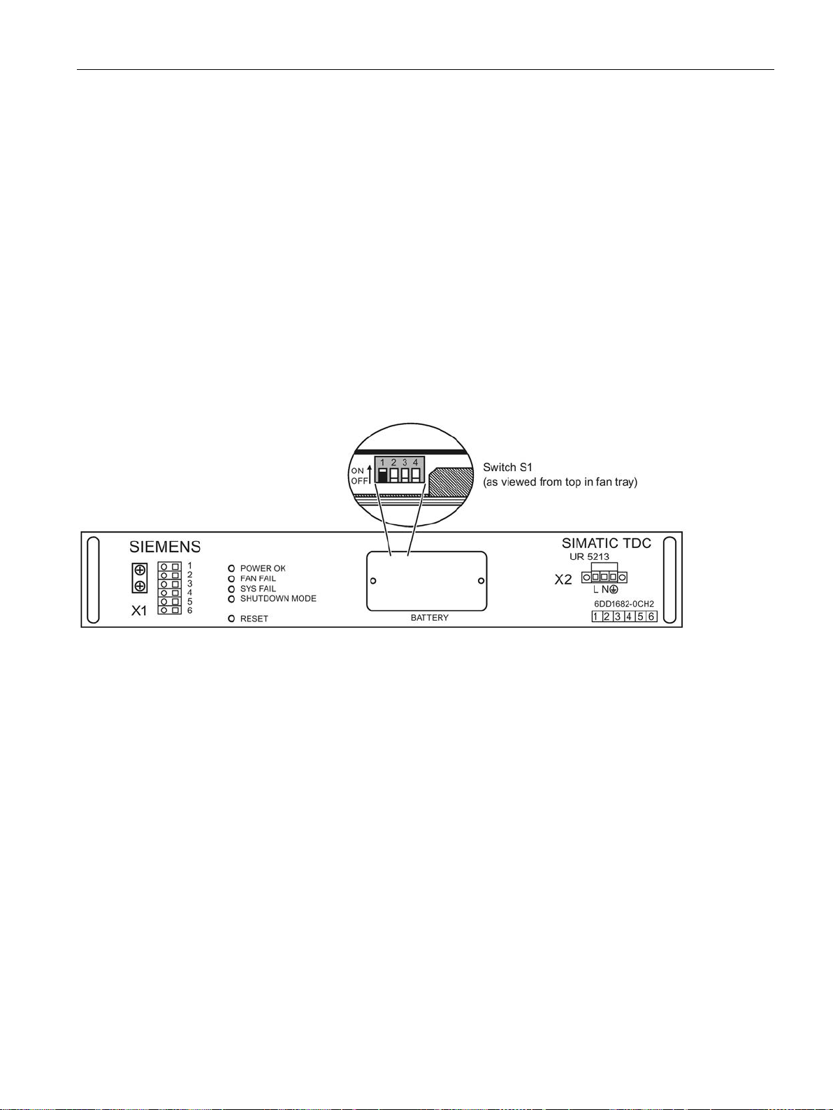
Rack
3.2.3
Control and display elements
X1
SHUTDOWN MODE
LED
RESET
BATTERY
X2
Aotewell Ltd
www.aotewell.com
Industry Automation
HongKong|UK|China
+86-755-8660-6182
3.2 Rack UR5213 (6DD1682-0CH2)
3 signaling relays, 230 V floating potential (3 x 2 contacts)
A system shutdown mode can be set in accordance with the switch position S1.4 (in the
battery box) as response to the failure of one or two fans.
The operating mode setting is indicated by the "SHUTDOWN MODE" LED on the front
panel.
● OFF = Shutdown on failure of two fans (SHUTDOWN MODE LED = off)
● ON = Shutdown on failure of one fan (SHUTDOWN MODE LED = on)
Figure 3-5 Front view of the fan tray
The four LEDs signal the operating state of the rack.
You can restart all modules by pressing the submerged pushbutton (rack RESET).
Backup battery compartment (1 x AA lithium battery)
Line voltage connection
SIMATIC TDC hardware
System Manual, 08/2017, A5E01114865-AL
55
Page 56

Rack
3.2.4
Status and fault displays
LED
Display
Rack state
POWER
green is on
fault-free operation
FAN FAIL
(red)
Off
fault-free operation
On
fault (at least one fan has failed)
SYSFAIL
(red)
Off
fault-free operation
On
System was stopped
SHUTDOWN Mode
tion of switch S1.4)
of switch S1.4)
3.2.5
Power supply
Mains connection
Note
Always use the integrated strain relief for the mains cable on the 3
Input voltage
85–264 V AC
Test voltage
Primary ↔ PE
1350 V AC
Power consumption
800 W (apparent power approx. 835 VA)
Conductor cross-section
3x1.5 mm2 (stranded wires dressed with wire end ferrules with
ISO insulating collars)
External fuse
In = 9 A
Alternatively, a slow-acting fuse may be used.
Note
A mains disconnect unit must be provided during installation of the rack.
Aotewell Ltd
www.aotewell.com
Industry Automation
HongKong|UK|China
+86-755-8660-6182
3.2 Rack UR5213 (6DD1682-0CH2)
Table 3- 2 Status displays for UR5213
(green or red)
(yellow)
red is on fault (refer to voltage monitoring)
On Shutdown on failure of two fans (corresponds to the OFF posi-
Flashing Shutdown on failure of one fan (corresponds to the ON position
Mains is connected to the 3-pin screw terminal block on the right side of the power supply
unit.
The pin assignment is printed onto the front panel.
(dimensioning)
-pin screw terminal block.
Is = <40 A (inrush peak)
The power supply is equipped with an internal 20 A fuse. This
means that only the mains supply has to be fused. It is recommended to use a standard 16 A thermo magnetic circuit-breaker
(B characteristic).
SIMATIC TDC hardware
56 System Manual, 08/2017, A5E01114865-AL
Page 57
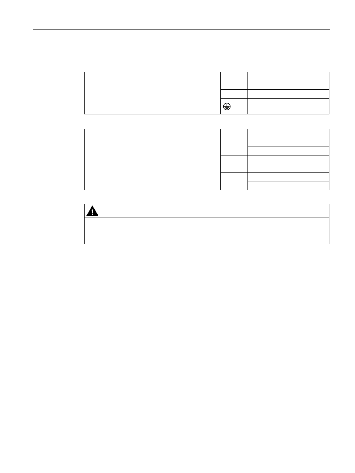
Rack
3.2.6
Wiring diagram
X2
Pin
Function
L
Line conductor
X1
Pin
Function
SYSFAIL signaling contact
NC contact
POWER signaling contact
NO contact
FAN FAIL signaling contact
NO contact
WARNING
PE/ground conductor
Aotewell Ltd
www.aotewell.com
Industry Automation
HongKong|UK|China
+86-755-8660-6182
3.2 Rack UR5213 (6DD1682-0CH2)
Screw terminal with screw lock (3*1.5 mm2, stranded
wires dressed with wire end ferrules with insulating
collars)
Make sure that the strain relief is properly mounted.
N Neutral conductor
PE/ground conductor
Cage clamp terminal (0.5 mm2 –1.5 mm2, stranded
wires dressed with wire end ferrules with insulating
collars)
Make sure that the strain relief is properly mounted.
1, 2
3, 4
5, 6
The
must be connected to the power supply. A PE/ground terminal
on the rack is inappropriate. The PE/ground conductor must be green with yellow stripe
(green/yellow).
Ungrounded installation of the rack is not planned.
SIMATIC TDC hardware
System Manual, 08/2017, A5E01114865-AL
57
Page 58

Rack
3.2.7
Voltage monitoring
Input voltage
Input voltage
Reaction
ACFAIL
output voltages <85V
Output voltage
Voltage monitoring functions at the power supply
outlet
Reaction
- 12 V in the range from -11 V to -13 V
System failure alarm
HWConfig
SYSFAIL
Aotewell Ltd
www.aotewell.com
Industry Automation
HongKong|UK|China
+86-755-8660-6182
3.2 Rack UR5213 (6DD1682-0CH2)
The input voltage is monitored for low level.
Undervoltage < approx. 85 V
Voltage dips ≤ 20 ms are buffered.
The power supply unit and therefore the system are restarted automatically on recovery from
a voltage dip below the permissible mains voltage.
The power on/off sequence (e.g. generation of a RESET or SYSFAIL signal) corresponds to
the reaction to manual operation of the mains switch.
All output voltages are monitored (e.g. for overload/short-circuit).
+5 V in the range from 4.75 V to 5.35 V “POWER OK” LED is lit green;
+ 3.3 V in the range from +3.18 V... +3.5 V
+ 12 V in the range from +11 V to +13 V
In all other cases, the “POWER OK” LED is lit red.
signal and CPU STOP, shutdown of
Select the "Object properties" in the "STOP" tab of
the relevant module to a system failure alarm (bus signal *
● Modules can reset their digital and analog outputs
● CPU modules can go into the "STOP" state ("H" is displayed permanently)
SIMATIC TDC hardware
58 System Manual, 08/2017, A5E01114865-AL
to configure the response of
=low):
Page 59
Rack
3.2.8
Battery backup
Battery connection
Technical specifications of the battery
Backup battery
Article number
6ES7971-0BA00
Rated voltage
3.6 V
Rated capacity
2.3 Ah
WARNING
Handling lithium batteries
Backup time
Aotewell Ltd
www.aotewell.com
Industry Automation
HongKong|UK|China
+86-755-8660-6182
3.2 Rack UR5213 (6DD1682-0CH2)
A backup battery must be installed in the power supply circuit to enable the backup of
configured values on power failure (using SAV function blocks).
Type 1 x Lithium AA
You may only use batteries that have been approved by Siemens!
Risk of injury, damage to assets, and emission of pollutants. Improper handling of a Lithium
battery may cause its explosion and incorrect disposal of used lithium batteries may lead to
emission of pollutants. For these reasons, you should strictly observe the following notes:
• Do not throw new or waste batteries into an open fire, or perform any soldering work on
the cell body (max. temperature 100° C), or recharge the battery - risk of explosion! Do
not open the battery and always replace it with one of the same type. Always order
replacements from Siemens. This ensures that you are in possession of a short circuitproof type.
• You should return waste batteries to the battery manufacturer, dispose of the batteries
as special waste at a recycling facility.
Sample calculation:
Capacity of the backup battery: 2.3 Ah, 63 % is assumed for calculation
Backup current: 200 µA (monitoring 20 µA + max. 180 µA for the slots, a CPU 551 needs
2.2 µA )
Backup time = 2.3 Ah * 0.63 / 200 µA = 7245 h ≙ 300 days
SIMATIC TDC hardware
System Manual, 08/2017, A5E01114865-AL
This time is valid for a rack that is switched off. Only the battery monitoring function draws a
current of 20 µA while the rack is powered on.
It is recommended to replace the batteries at annual intervals. The backup function is
deactivated while the fan tray is removed.
59
Page 60
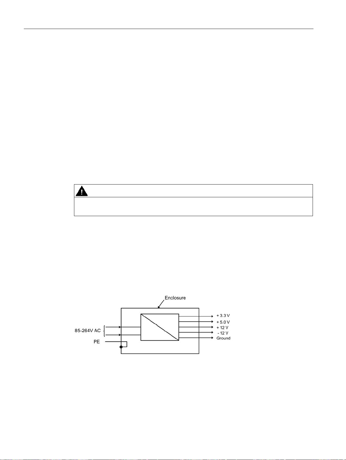
Rack
Battery voltage monitoring
Battery replacement
3.2.9
Modules
WARNING
3.2.10
Power supply potentials
Aotewell Ltd
www.aotewell.com
Industry Automation
HongKong|UK|China
+86-755-8660-6182
3.2 Rack UR5213 (6DD1682-0CH2)
The CPU module inserted in slot 1 detects missing or low backup batteries and signals these
states with a flashing "b".
Unscsrew and remove the lid of the battery compartment to remove the battery. Observe
correct polarity when inserting the battery. You should also take care not to bend the
connection tabs of the battery holder during replacement.
You should always replace the battery while the rack is powered on in order to prevent data
loss.
Make sure that the modules you insert are properly aligned in their relevant slot.
Do not push the modules towards the left when inserting these, because you would risk
damage to the ESD braid of the modules already inserted.
Observe this particularly at slot 1, as a metal spring has been installed in this slot.
In SIMATIC TDC, the ground connections of all secondary voltages are grouped and bonded
to the rack enclosure in order to improve the signal to interference ratio and to ensure proper
grounding.
SIMATIC TDC hardware
60 System Manual, 08/2017, A5E01114865-AL
Page 61
Rack
3.2.11
Ventilation/cooling
Note
For more information, refer to section "
Fan monitoring
WARNING
CAUTION
WARNING
Aotewell Ltd
www.aotewell.com
Industry Automation
HongKong|UK|China
+86-755-8660-6182
3.2 Rack UR5213 (6DD1682-0CH2)
The rack is equipped with three fans for forced convection of the modules and with one fan
for the system power supply.
Since the rack is not equipped with an air filter, you should provide a filter on the cabinet if
necessary.
Equipotential bonding (Page 22)".
The fans are monitored (speed). Activation of the monitoring function is delayed in order to
enable the reliable startup of the rack after you switched on power.
On failure of one or two fans, the power supply is shut down depending on the operating
mode in order to prevent thermal destruction of the modules.
Select the operating mode (SHUTDOWN MODE) using switch S1.4 that is integrated in the
power supply. The power supply is shut down if one fan has failed and switch position "ON"
is set, or if two fans have failed and switch position "OFF" is set.
To set switch S1, unscrew the front panel and slightly pull it forward until you can reach the
switch through the gap. Switch off power to the rack before you open the panel.
Switch off power to the rack before you remove the front panel screws.
Observe the corresponding ESD Directives.
The operating mode setting is indicated by the "SHUTDOWN MODE" LED on the front
panel.
Refer to chapter “Status and fault displays”.
Always set the “Shutdown mode” dip switch S1.4 to “ON” for modules requiring forced
convection (e.g. CPU551) at air intake temperatures from 0 C to 60 °C.
You may only set the position of switch S1.4 to "OFF” if it can be assured that the air intake
temperature at the rack does not exceed 35 °C.
The power supply is not shut down on failure of a single fan, but the corresponding
backplane bus signal (FANAL*) is activated and can be detected by the configuration
software.
SIMATIC TDC hardware
System Manual, 08/2017, A5E01114865-AL
61
Page 62

Rack
Signaling relay
Signaling relay
Terminal X1
Contact in switched off
state:
Contact in error-free op-
eration
LED in error-free operation
SYSFAIL
1,2
Closed
Closed
Off
FAN FAIL
5,6
Open
Closed
Off
Aotewell Ltd
www.aotewell.com
Industry Automation
HongKong|UK|China
+86-755-8660-6182
3.2 Rack UR5213 (6DD1682-0CH2)
Three 230 V signaling relays with floating potential facilitate external evaluation of the rack's
system states.
Table 3- 3 Signaling relay
POWER 3,4 Open Closed green is on
SIMATIC TDC hardware
62 System Manual, 08/2017, A5E01114865-AL
Page 63

Rack
3.2.12
Technical specifications
Article number
Rack UR5213
6DD1682-0CH2
General data
Degree of protection
IP 20
Protection class
Protection class 1 with PE/ground conductor
Operating temperatures
0 °C to +60 °C
Relative air humidity
5 % to 95 %, no condensation
Storage: 1080 hPa to 660 hPa
Power input
198 V DC to 253 V DC (extended range input)
Max. inrush current
< 40 A
Power factor
EN 61000-3-2
Overvoltage category
II
Pollution degree
2
Power failure backup
min. 20 ms
Aotewell Ltd
www.aotewell.com
Industry Automation
HongKong|UK|China
+86-755-8660-6182
3.2 Rack UR5213 (6DD1682-0CH2)
Safety EN 61131-2
Storage temperatures -40 °C to +70 °C
Atmospheric pressure Operation: 1080 hPa to 795 hPa
Input voltage
• Rated value
• Permissible range
120/230 V AC
220 V DC
85 V AC to 264 V AC
Rated input current
• At 120 V AC
• At 230 V AC
• At 220 V DC
Line frequency
• Rated value
• Permissible range
SIMATIC TDC hardware
System Manual, 08/2017, A5E01114865-AL
4.45 A
2.3 A
2.38 A
50/60 Hz
47-63 Hz
63
Page 64

Rack
Output voltages
Rated output voltage
Max. output current load on the module type
+5 V
36 A
+3.3 V
44 A
+12 V
4.6 A
Note
If using other modules, you must check the individual maximum currents and
maximum load of 320 W.
do not
Battery
max. 180 µA for slots 1-21
Relay contacts
Rated voltage (AC)
230 V (max. 264 V)
Rated current
2 A
Dimensions
Number of rack slots
21
Dimensions W x H x D [mm]
approx. 482.6 x 354.9 x 343
Weight
Approx. 20 kg
Aotewell Ltd
www.aotewell.com
Industry Automation
HongKong|UK|China
+86-755-8660-6182
3.2 Rack UR5213 (6DD1682-0CH2)
The following lists the maximum current load on the output voltages of the rack.
-12 V 4 A
Total output power may not exceed 320 W. This must be ensured i your configuration.
The output currents are listed in the respective description.
The output power limit of 320 W is not exceeded even in a full assembly of the rack
consisting of the module types CPU551, SM500, CP51M1, CP50M1 and CP52A0.
verify the
All outputs are sustained short circuit-proof and
Current load Approx. 20 µA for the monitoring function and
need a basic load.
SIMATIC TDC hardware
64 System Manual, 08/2017, A5E01114865-AL
Page 65
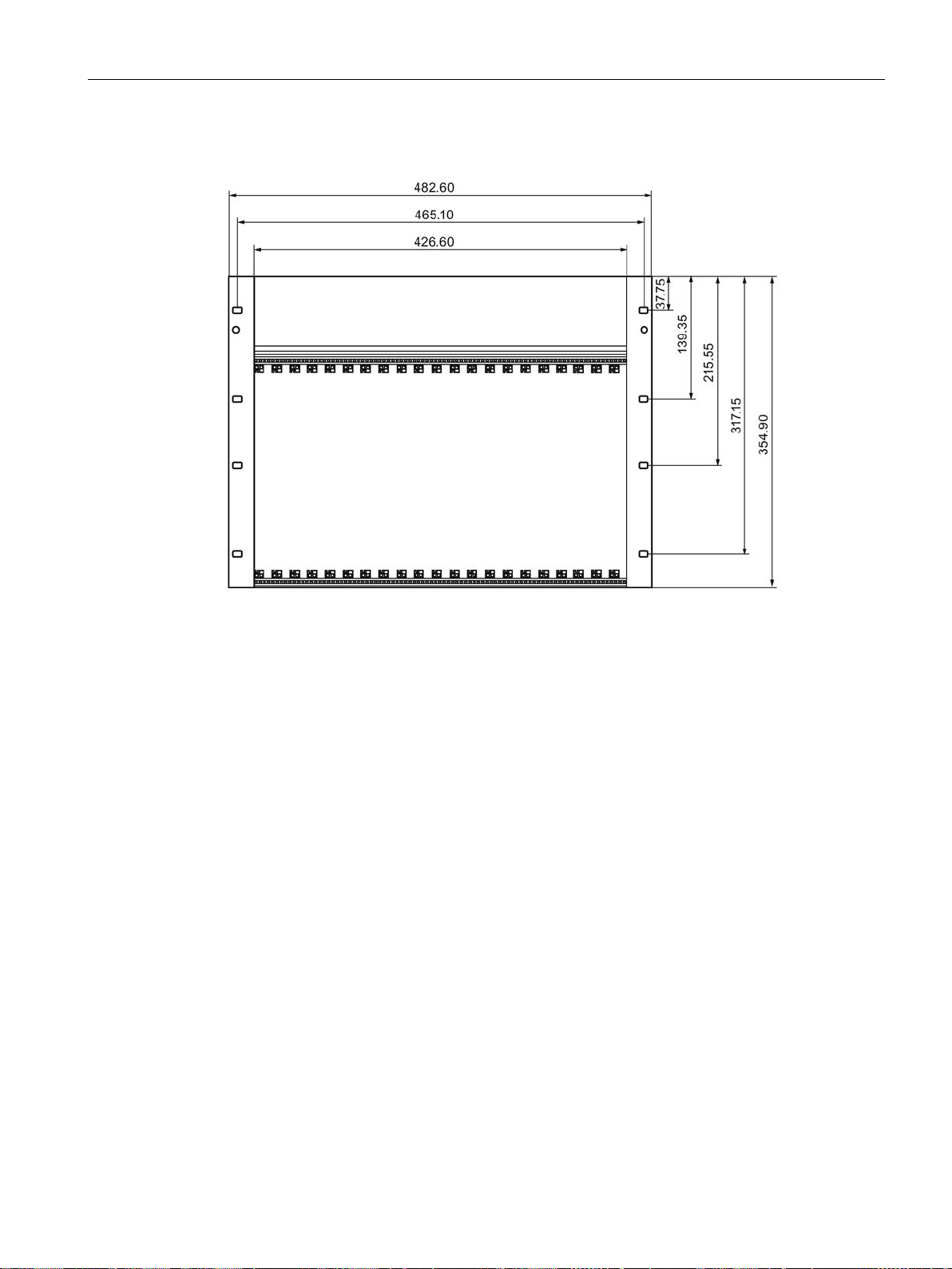
Rack
Dimensional drawing
Aotewell Ltd
www.aotewell.com
Industry Automation
HongKong|UK|China
+86-755-8660-6182
3.2 Rack UR5213 (6DD1682-0CH2)
Figure 3-6 Dimensional drawing of rack UR5213
SIMATIC TDC hardware
System Manual, 08/2017, A5E01114865-AL
65
Page 66
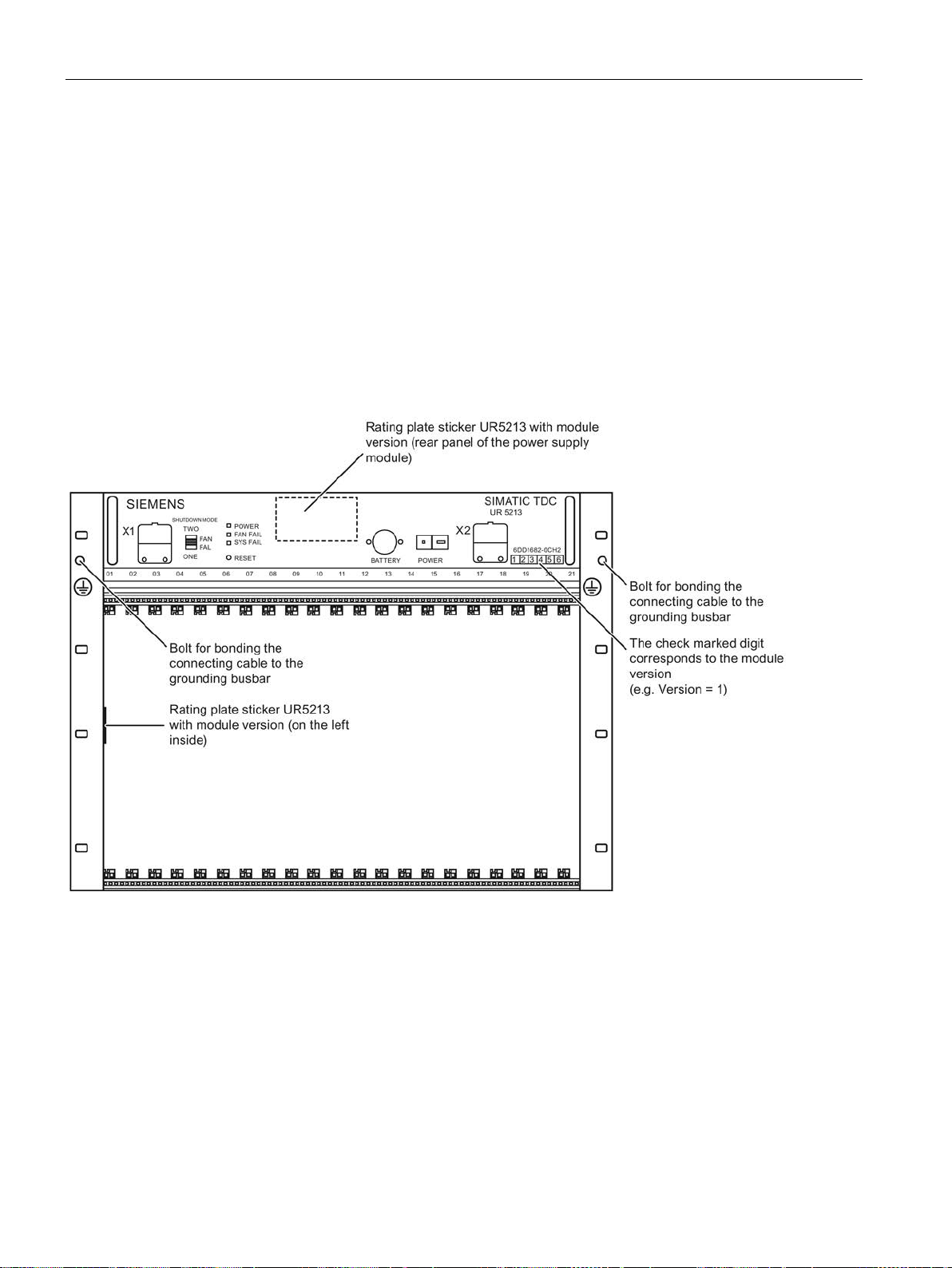
Rack
3.3
Rack UR5213 (6DD1682-0CH0)
3.3.1
Areas of application
3.3.2
Mechanical layout
PS5213 power supply
Aotewell Ltd
www.aotewell.com
Industry Automation
HongKong|UK|China
+86-755-8660-6182
3.3 Rack UR5213 (6DD1682-0CH0)
Rack UR5213 with 21 slots forms the mechanical base for SIMATIC TDC and features an
integrated system power supply and integrated system fans. A high-performance 64-bit
backplane bus supports high-speed data exchange between the inserted modules.
Figure 3-7 Rack UR5213 (front view)
The power supply with three fans is inserted and screw mounted in the upper section of the
rack.
SIMATIC TDC hardware
66 System Manual, 08/2017, A5E01114865-AL
Page 67
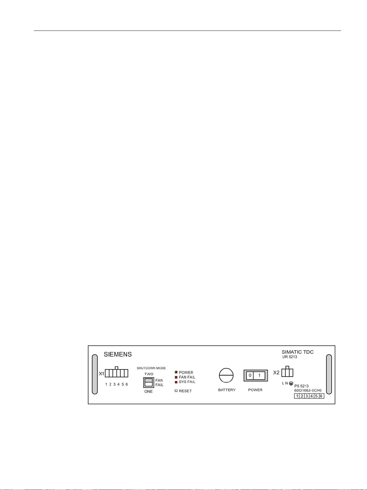
Rack
3.3.3
Control and display elements
X1
SHUTDOWN MODE
LED
RESET
BATTERY
POWER
X2
Front panel
Aotewell Ltd
www.aotewell.com
Industry Automation
HongKong|UK|China
+86-755-8660-6182
3.3 Rack UR5213 (6DD1682-0CH0)
3 signaling relays, 230 V floating potential (3 x 2 contacts)
A system stop triggered by fan failure can be set based on the switch position, i.e. “ONE”
setting for failure of one fan, or “TWO” setting for failure of two fans.
The three LEDs display the rack's operating status.
You can restart all modules by pressing the submerged pushbutton (rack RESET).
Compartment for backup batteries
(2 x 1.5 V leak-proof alkaline manganese cells type AA)
Mains switch
Line voltage connection
SIMATIC TDC hardware
System Manual, 08/2017, A5E01114865-AL
Figure 3-8 Front view of the power supply unit
67
Page 68

Rack
3.3.4
Status and fault displays
LED
Display
Rack state
POWER
green is on
fault-free operation
FAN FAIL
(red)
Off
fault-free operation
On
fault (at least one fan has failed)
SYSFAIL
(red)
Off
fault-free operation
On
System was stopped
3.3.5
Power supply
Mains connection
Derating 85 – 90 V
Power consumption
800 W (apparent power approx. 835 VA)
L
Phase conductor L
N
Neutral conductor N
Alternatively, a slow-acting fuse may be used.
Aotewell Ltd
www.aotewell.com
Industry Automation
HongKong|UK|China
+86-755-8660-6182
3.3 Rack UR5213 (6DD1682-0CH0)
Table 3- 4 Status displays for UR5213
(green or red)
red is on fault (refer to voltage monitoring)
Mains is connected to the 3-pin screw terminal block on the right side of the power supply
unit.
The pin assignment is printed onto the front panel.
Input voltage 90 - 264 V AC
Dielectric strength
• Mains inlet / PE
• Mains inlet / SELV
• SELV / PE
External fuse
(dimensioning)
1500 V AC
3000 V AC
500 V AC
Ground conductor PE
In = 9 A
Is = <50 A (inrush peak)
The power supply is equipped with an internal 12 A fuse. This
means that only the mains supply has to be fused. It is recommended to use a standard 16 A thermo magnetic circuit-breaker
(B characteristic).
SIMATIC TDC hardware
68 System Manual, 08/2017, A5E01114865-AL
Page 69

Rack
WARNING
PE/ground conductor
Aotewell Ltd
www.aotewell.com
Industry Automation
HongKong|UK|China
+86-755-8660-6182
3.3 Rack UR5213 (6DD1682-0CH0)
The
on the rack is inappropriate. The PE/ground conductor must be green with yellow stripe
(green/yellow).
must be connected to the power supply. A PE/ground terminal
SIMATIC TDC hardware
System Manual, 08/2017, A5E01114865-AL
69
Page 70

Rack
3.3.6
Voltage monitoring
Input voltage
Input voltage
Reaction
ACFAIL
Output voltage
Voltage monitoring functions at the power supply
outlet
Reaction
- 12 V in the range from -11 V to -13 V
System failure alarm
HWConfig
SYSFAIL
Aotewell Ltd
www.aotewell.com
Industry Automation
HongKong|UK|China
+86-755-8660-6182
3.3 Rack UR5213 (6DD1682-0CH0)
The input voltage is monitored for low level.
Undervoltage < approx. 90 V
Voltage dips ≤ 15 ms are buffered.
The power supply and therefore the system will be restarted on recovery from voltage dips to
approx. 5 % of the rated mains voltage and a duration longer than approx. 3 seconds.
The power on/off sequence (e.g. generation of a RESET or SYSFAIL signal) corresponds to
the reaction to manual operation of the mains switch.
The rack goes into standby state following voltage interruption of a duration shorter than
approx. 3 and dip to no less than approx. 5 % of the rated mains voltage. A usual power off
sequence precedes this state.
This state can only be cleared by cycling power off and on by means of the mains switch.
All output voltages are monitored (e.g. for overload/short-circuit).
+5 V in the range from 4.75 V to 5.35 V “POWER OK” LED is lit green;
+ 3.3 V in the range from +3.18 V... +3.5 V
+ 12 V in the range from +11 V to +13 V
•
output voltages <85V
signal and CPU STOP, shutdown of
In all other cases, the “POWER OK” LED is lit red.
Select the "Object properties" in the "STOP" tab of
the relevant module to a system failure alarm (bus signal *
● Modules can reset their digital and analog outputs
● CPU modules can go into the "STOP" state ("H" is displayed permanently)
SIMATIC TDC hardware
70 System Manual, 08/2017, A5E01114865-AL
to configure the response of
=low):
Page 71

Rack
3.3.7
Battery backup
Battery connection
Battery voltage monitoring
Battery replacement
while installing
measures
replacement
Aotewell Ltd
www.aotewell.com
Industry Automation
HongKong|UK|China
+86-755-8660-6182
3.3 Rack UR5213 (6DD1682-0CH0)
In order to backup configured values to memory on power failure (using the SAV function
blocks), you need to install two commonly available size AA leak-proof alkaline manganese
batteries with a rated voltage of 1.5 V in the power supply circuit.
It is recommended to replace the batteries at annual intervals.
The backup function is no longer available if you remove the power supply unit (e.g. in the
case of malfunction, or fan replacement).
The CPU module inserted in slot 1 detects missing or low backup batteries and signals these
states with a flashing "b".
You should always replace the battery while the rack is powered on in order to prevent data
loss.
Note that
preparation for its
the battery you also need to take corresponding
.
in
SIMATIC TDC hardware
System Manual, 08/2017, A5E01114865-AL
71
Page 72

Rack
3.3.8
Ventilation/cooling
Fan monitoring
WARNING
Fan replacement
40,000 operating hours
Signaling relay
Signaling relay
Terminal X1
Contact in switched off state
Contact in error-free op-
eration
LED in error-free operation
SYSFAIL
1,2
Closed
Closed
Off
POWER
3,4
Open
Closed
green is on
FAN FAIL
5,6
Open
Closed
Off
Aotewell Ltd
www.aotewell.com
Industry Automation
HongKong|UK|China
+86-755-8660-6182
3.3 Rack UR5213 (6DD1682-0CH0)
The PS5213 power supply is equipped with three fans.
Since the rack is not equipped with an air filter, you should provide a filter on the cabinet if
necessary.
The fans are monitored (speed). Activation of the monitoring function is delayed in order to
enable the reliable startup of the rack after you switched on power.
On failure of one or two fans, the power supply is shut down in order to prevent thermal
destruction of the modules. Use the "Shutdown Mode" dip switch to select the mode (the
switch has the “ONE” or “TWO” settings). With switch position “ONE”, a power supply
shutdown is triggered on failure of at least one fan and in switch position “TWO” by the
failure of at least two fans.
Always set the “Shutdown mode” dip switch S1.4 to “ONE” for modules requiring forced
convection (e.g. CPU550) at air intake temperatures from 0 C to 55 °C.
You may only set switch position "TWO" if it can be assured that the air intake temperature
at the rack does not exceed 35 °C. The power supply is not shut down on failure of a single
fan, but the corresponding backplane bus signal (FANAL*) is activated and can be detected
by the configuration software.
At an ambient temperature of 55 °C, it is recommended to replace the fans at intervals of
approx.
Users cannot replace the fans.
Three 230V signaling relays with floating potential facilitate external evaluation of the rack's
system states.
Table 3- 5 Signaling relay
. The power supply must be removed for fan replacement.
SIMATIC TDC hardware
72 System Manual, 08/2017, A5E01114865-AL
Page 73

Rack
3.3.9
Technical specifications
Article number
Rack UR5213
6DD1682-0CH0
General data
Degree of protection
IP 20
Protection class
Protection class 1 with PE/ground conductor
Storage temperatures
-40 °C to +70 °C
Operating temperatures
0 °C to +55 °C
Relative air humidity
5 % to 95 %, no condensation
Storage: 1080 hPa to 660 hPa
Power input
Input voltages (AC)
90 V - 264 V
Rated input current
Typically < 10 A
Max. inrush current
< < 50 A
Frequency
47 Hz to 63 Hz
Power factor
EN 61000-3-2
Power failure backup
min. 15 ms
Output voltages
Rated output voltage
Output current
+5 V
60 A
+3.3 V
60 A
+12 V
8 A
-12 V
8 A
do not
Battery
Current load
approx. 10 µA for each inserted CPU module
Aotewell Ltd
www.aotewell.com
Industry Automation
HongKong|UK|China
+86-755-8660-6182
3.3 Rack UR5213 (6DD1682-0CH0)
Safety EN 61131-2
Atmospheric pressure Operation: 1080 hPa to 795 hPa
All outputs are sustained short circuit-proof and
need a basic load.
SIMATIC TDC hardware
System Manual, 08/2017, A5E01114865-AL
73
Page 74

Rack
Dimensions
Number of rack slots
21
Dimensions W x H x D [mm]
approx. 482.6 x 354.9 x 343
Weight
Approx. 20 kg
3.4
Slot covers
Application
Article number
Slot cover SR51
6DD1682-0DA1
Aotewell Ltd
www.aotewell.com
Industry Automation
HongKong|UK|China
+86-755-8660-6182
3.4 Slot covers
Slot cover SR51 is used to protect unused slots of the rack. This is necessary to ensure
proper ventilation and EMC compatibility of the system.
SIMATIC TDC hardware
74 System Manual, 08/2017, A5E01114865-AL
Page 75

4
4.1
CPU module CPU555
4.1.1
Areas of application
Note
Note the following for the CPU555:
•
•
•
•
Note
Note the following for operation with other CPUs:
•
not
•
not
Aotewell Ltd
www.aotewell.com
Industry Automation
HongKong|UK|China
+86-755-8660-6182
CPU555 is a graphically freely configurable processor module, enabling the implementation
of sophisticated highly dynamic control functions.
Use cases include:
● Roll nip controls
● Hydraulic positioning functions
● Strip cooling systems
● HVDCT control systems (high voltage DC transmission)
CPU555 can only be used in the rack UR6021.
CPU555 can only be configured with a version V8.1 or higher of the D7-SYS automation
The floating point unit used supports Floating Point data types, operations and exception
The CPU555 does not apply substitute values for invalid real values. This method
Operation of the CPU555 together with a CPU551 is
Operation of the CPU555 together with a CPU550 is
software.
handling as defined in IEEE Standard 754 (2008). Floating point numbers are calculated
internally with 80 bits. This results in fewer rounding errors as compared to calculations
with only 64 bits (CPU551).
provides higher performance. Typically, invalid real values result from corrupted data
from external interfaces. Calculating with invalid real values can have unintended results.
Checking the input values with the CHK_R function block is recommended. With the
CHK_R function block, you can assign a substitute value for an error scenario.
approved.
approved.
SIMATIC TDC hardware
System Manual, 08/2017, A5E01114865-AL
75
Page 76

CPU modules
Note
Note the following for operation with modules:
•
•
•
•
•
•
4.1.2
Control and display elements
LED display
Acknowledge button S1
ASI
Aotewell Ltd
www.aotewell.com
Industry Automation
HongKong|UK|China
+86-755-8660-6182
4.1 CPU module CPU555
Operation of the CPU555 with the CP5100 and CP50M0 modules that are being phased
out is not possible.
Use of a CP50M1 in combination with a CPU555 is only possible as of a firmware version
≥ 4
Use of a CP51M1 in combination with a CPU555 is only possible as of a functional status
≥ 8
Use of a CP52A0 with article number 6DD1660-0BH0 in combination with a CPU555 is
only possible as of a functional status ≥ 9
Use of a CP53M0 in combination with a CPU555 is only possible as of a functional status
≥ 9
Use of an SM500 in combination with a CPU555 is only possible as of a functional status
≥ 13
The processor number, states and faults are displayed using a 5x7 dot matrix LED array.
This button has two functions:
● Clearing the fault display:
The acknowledge button can be used to clear sporadic or non-critical fault displays on the
5x7 dot matrix LED. An additional fault is displayed after the first one has been
acknowledged.
● Digital signal input can be evaluated using the
function block.
SIMATIC TDC hardware
76 System Manual, 08/2017, A5E01114865-AL
Page 77
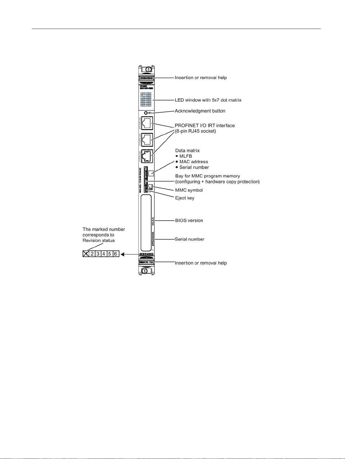
CPU modules
Front panel
Aotewell Ltd
www.aotewell.com
Industry Automation
HongKong|UK|China
+86-755-8660-6182
4.1 CPU module CPU555
Figure 4-1 Front view of CPU555
SIMATIC TDC hardware
System Manual, 08/2017, A5E01114865-AL
77
Page 78

CPU modules
4.1.3
Status and fault displays
Note
Maximum assembly
The CPU module CPU555 can only be operated in the rack UR6021.
A maximum of eight CPU555 can be inserted in one UR6021.
Display
Operating and fault states
Can be
cleared with
S1
1...20
User program is running
A User error
Diagnostics event, user-defined by means of USF function block
All 35 dots off
of a colored circle and consecutive numbers.
All 35 dots
flashing
All 35 dots on
Colored circle
flashing
Aotewell Ltd
www.aotewell.com
Industry Automation
HongKong|UK|China
+86-755-8660-6182
4.1 CPU module CPU555
The dot matrix shows the configured number of the CPU module (1 to 20) in normal
operation. Faults are indicated by a letter that informs you of the type of fault.
Slow alternation between the light and dark state of the dot matrix is referred to as flashing in
the following table.
Table 4- 1 Operating and fault states of CPU555
Configured number of the CPU module in normal operation.
User program is running
Initialization phase:
User program is not running
Individual initialization phases during startup are indicated by means
Module failure:
User program is not running
• Hardware failure => replace CPU555
• Fatal software error => contact the Hotline
Partial power failure, FPGA1 failure or errors on the module:
User program is not running
• Hardware failure => replace CPU555
• Fatal hardware fault => contact the Hotline
Initialization phase:
User program is not running
No
Yes
No
No
No
No
SIMATIC TDC hardware
78 System Manual, 08/2017, A5E01114865-AL
Page 79

CPU modules
Display
Operating and fault states
Can be
cleared with
S1
0 Initialization error
of those which display a "0".
b Monitoring error
C Communication error
(Initial error = flashing; additional errors = continuous display)
d User stop
Module is in STOP, triggered by this CPU itself.
Aotewell Ltd
www.aotewell.com
Industry Automation
HongKong|UK|China
+86-755-8660-6182
4.1 CPU module CPU555
User program is not running
Diagnostics should start at the CPU module that was the first to dis-
play fault message “0”.
• Flashing "0" Faults on this module
• Permanent "0": Faults on a different module
If none of the CPU modules can be identified as having been the first
one, then the one inserted to the extreme left should first be selected
User program is running
Low-priority errors during initialization that allow the start of normal
operation and that are detected in the background process, e.g.: e.g.
• missing or low backup battery
• Missing program memory module
• Fan failure
• Invalid real value
• PN bus/group error (flashing; faulty module)
Note: The PN bus/group error can also be acknowledged while it
is still pending. After acknowledgment, this error is not displayed
again until it occurs again (new incoming event/error).
User program is running
Incorrect configuration of communication, or connection error
For more information on diagnostics functions, refer to the manual
"D7-SYS - STEP 7, CFC and SFC configuring
(http://support.automation.siemens.com/WW/view/de/8776786/0/en)",
chapter Basic software, section "Diagnostics".
No
Yes
No
User program is not running
Selection in the "Target system/Operating state" menu
User stop results in a stop of all CPUs in the same rack.
• Permanent "d":
Module is in STOP, triggered by another CPU.
• Flashing "d"
SIMATIC TDC hardware
System Manual, 08/2017, A5E01114865-AL
No
79
Page 80

CPU modules
Display
Operating and fault states
Can be
cleared with
S1
E Task Manager error
chapter Basic software, section "Diagnostics".
H System error
chapter Basic software, section "Diagnostics".
Aotewell Ltd
www.aotewell.com
Industry Automation
HongKong|UK|China
+86-755-8660-6182
4.1 CPU module CPU555
User program is running
• Flashing "I": Initial error
• Static "I":
Sequential error after a lower priority error
The following errors are possible:
Cycle errors
•
A task could not be completed within the sampling time.
Task overflow
•
If a task that has not been not assigned top priority but needs to
be restarted.
•
No free local buffer
The data buffer is no longer released. The task start will be
skipped.
•
Software time monitoring
If the basic sampling time is not processed four times in succession. The basic clock cycle timer is re-initialized with the configured basic sampling time and processing is continued.
For more information on diagnostics functions, refer to the manual
"D7-SYS - STEP 7, CFC and SFC configuring
(http://support.automation.siemens.com/WW/view/de/8776786/0/en)",
Yes
User program is not running
Hardware or software problems causing a program crash.
• Flashing "H" Faults on this module
• Permanent "H": Faults on a different module
For more information on diagnostics functions, refer to the manual
"D7-SYS - STEP 7, CFC and SFC configuring
(http://support.automation.siemens.com/WW/view/de/8776786/0/en)",
No
SIMATIC TDC hardware
80 System Manual, 08/2017, A5E01114865-AL
Page 81

CPU modules
4.1.4
Application notes and immunity to interference
NOTICE
CPU555 in the UR6021 rack
Note
For more information on fan operation, refer to section "
For more information on EMC and environmental conditions, refer to section "
technical specifications
Note
Shutdown behavior of various CPU modules
The various CPU modules exhibit slight time differences in their shutdown behavior when the
power supply is interrupted.
Aotewell Ltd
www.aotewell.com
Industry Automation
HongKong|UK|China
+86-755-8660-6182
4.1 CPU module CPU555
● Fan operation is necessary.
● Interference-proof operation is only possible if the CPU555 is firmly attached to the rack.
Insert the module and then bolt it onto the rack accordingly (two screw heads, see
"Control and display elements (Page 76)").
● The module may not be inserted or removed while the rack is on live voltage.
● A CPU must be inserted into the first slot of the rack.
CPU555 may only be used in the rack UR6021.
No CPU555 may be inserted in slot 21 when the UR6021 rack is used.
Rack (Page 39)".
General
(Page 37)".
SIMATIC TDC hardware
System Manual, 08/2017, A5E01114865-AL
81
Page 82
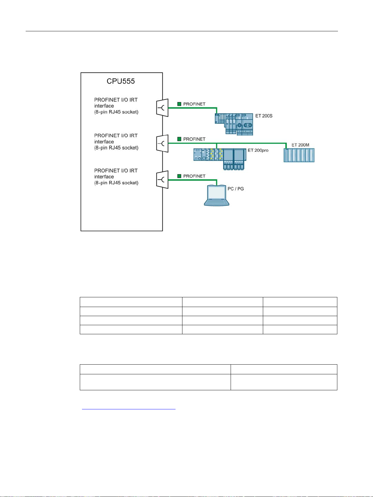
CPU modules
4.1.5
Connection options
4.1.6
Additional components
Component
Designation
Article No.
Program memory (2 MB)
S7 MICRO MEMORY CARD
6ES7953-8LL31-0AA0
Program memory (4 MB)
S7 MICRO MEMORY CARD
6ES7953-8LM31-0AA0
Program memory (8 MB)
S7 MICRO MEMORY CARD
6ES7953-8LP31-0AA0
Designation
Article No.
RJ45/RJ45, dressed with 2 x RJ45 connectors, length ...
Aotewell Ltd
www.aotewell.com
Industry Automation
HongKong|UK|China
+86-755-8660-6182
4.1 CPU module CPU555
Figure 4-2 Connection examples of CPU555
Table 4- 2 Additional components for CPU555
Table 4- 3 Connecting cable
SIMATIC NET, Industrial Ethernet TP XP CORD
For information on additional products, refer to: Product catalog
(https:eb.automation.siemens.com)
6XV1870-3R...
SIMATIC TDC hardware
82 System Manual, 08/2017, A5E01114865-AL
Page 83

CPU modules
4.1.7
Pin assignments
PROFINET I/O interface (X1 P1 R PN (LAN), X1 P2 R PN (LAN), X1 P3 PN (LAN))
PIN
Designation
1
TXP (Transmit Data +)
3
RXP (Receive Data +)
4
n.c.
5
n.c.
6
RXN (Receive Data -)
7
n.c.
8
n.c.
Enclosure
PE (shield)
4.1.8
Note on firmware update
Note
Updating the firmware
•
•
and feature enhancements.
NOTICE
No firmware update during operation
NOTICE
Qualified Personnel
Aotewell Ltd
www.aotewell.com
Industry Automation
HongKong|UK|China
+86-755-8660-6182
4.1 CPU module CPU555
The PROFINET I/O IRT connection (10/100 Mbps) is connected to the 8-pole RJ-45 plug
socket with polarity reversal protection.
Table 4- 4 Pin assignment of X1 P1 R PN (LAN), X1 P2 R PN (LAN), X1 P3 PN (LAN)
(RJ-45 socket)
2 TXN (Transmit Data -)
Firmware updates are available, if needed, on the Internet
(http://www.siemens.com/automation/service&support) under "Downloads".
Check regularly if firmware updates are available.
Always install the latest firmware on the CPU555 to receive the latest security updates
Note that a firmware update cannot take place during operation but only at plant standstill.
Only qualified personnel are permitted to perform the firmware update (see Qualified
personnel (Page 13))!
SIMATIC TDC hardware
System Manual, 08/2017, A5E01114865-AL
83
Page 84

CPU modules
Display
Operating state
Initialization phase
●
Firmware start (flashing)
0
Operating system start
1...9
Operating system initialization / Startup
Update
F
Firmware update in progress (F flashing)
✓
Firmware update completed
4.1.9
Technical specifications/performance features
Note
CPU555 in the UR6021
The CPU module CPU555 can only be operated in the rack UR6021.
UR6021 can be equipped with a maximum of eight CPU555.
Article number
CPU module CPU555
6DD1600-0BB0
CPU
Processor
64-bit Intel CPU
Clock frequency
2 GHz
Communications processor
32-bit CPU
Clock frequency
450 MHz
Note
Removal and insertion
Removal and insertion of the module is not permitted
Aotewell Ltd
www.aotewell.com
Industry Automation
HongKong|UK|China
+86-755-8660-6182
4.1 CPU module CPU555
Table 4- 5 Operating states of the CPU555 during the firmware update
LED test (approx. 1 sec)
during operation.
SIMATIC TDC hardware
84 System Manual, 08/2017, A5E01114865-AL
Page 85

CPU modules
Processor
SDRAM
2 GB DDR3-1333 MHz (667 MHz)
Communications processor
SDRAM
256 MB DDR2-400 (150 MHz)
Shared communication memory
SRAM (battery buffered)
1 MB
Module slots
Time
Resolution
0.1 ms
Fast CPU-CPU communication
Programming
Aotewell Ltd
www.aotewell.com
Industry Automation
HongKong|UK|China
+86-755-8660-6182
4.1 CPU module CPU555
Caches
Cache
Number 3
Allocation of the slots
1)
PMC/XMC plug-in cards are currently not provided.
• L1 cache: 32 KB data + 32 KB instruction
• L2 cache: 256 KB data/instruction
• L3 cache: 3 MB
• L1 cache: 32 KB data + 32 KB instruction
• Program memory S7 MMC (X4)
1)
• PMC-/XMC plug-in cards (X5)
CPU555 supports P0 functionality.
Each CPU555 can communicate with up to 7 additional CPU555 by means of the PCIe
interface via the backplane bus (P0 connector). This means that a point-to-point connection
always exists between any two CPU555 modules (see Areas of application (Page 39)).
The user program executed on the CPU module is configured on a PC using STEP 7 /
HW Config and CFC and then downloaded to program memory.
The program memory must be located in the CPU module slot provided (X4).
Direct user program download from the PC to program memory in the CPU module via
PROFINET interface (online loading).
SIMATIC TDC hardware
System Manual, 08/2017, A5E01114865-AL
85
Page 86

CPU modules
User program size
Utilization
Program memory
PROFINET interfaces
1) All X1 interfaces have the same IP address
I/O address range
Inputs
8192 bytes
Outputs
8192 bytes
Process image partition
Quantity
1
Address area
Inputs, max.
8192 bytes
Outputs, max.
8192 bytes
Aotewell Ltd
www.aotewell.com
Industry Automation
HongKong|UK|China
+86-755-8660-6182
4.1 CPU module CPU555
The size of the user program (compressed to approx. 50 %) that was downloaded to
program memory and the size of free program memory can be viewed in the CFC by
selecting the following menu command:
● PLC / Load / Info
Average load (measured with block PSL) should not exceed 90%, since this may lead to
sporadic overload.
The user program created in CFC is downloaded to program memory. Program memory
features Flash EPROM (2, 4 or 8 MB).
Program memory for user program: See Additional components (Page 82)
LAN interfaces
• Support of distributed I/O
• Operating control and monitoring
• Communication with a PC
• Download function
• TCP/UDP communication with other CPUs
• Set time of day
1)
PROFINET I/O interfaces
• X1 P1 R PN (LAN): 10/100 Mbps
• X1 P2 R PN (LAN): 10/100 Mbps
• X1 P3 PN (LAN): 10/100 Mbps
SIMATIC TDC hardware
86 System Manual, 08/2017, A5E01114865-AL
Page 87

CPU modules
Voltage, currents
Rated voltages at 25 °C
Typical current consumption
+5 V
4.26 A (max. 7.98 A)
Backup battery
3 µA (max. 27 µA)
Power losses/fan
Typical power losses (5 V / 3.3 V)
31 W (21.3 W / 9.7 W)
Fan required
Yes
Dimensions
Number of slots required in the rack
1
Dimensions W x H x D [mm]
20 x 233 x 160
Weight
0.34 kg
Degree of protection
Degree of protection according to DIN 40050
IP00
Aotewell Ltd
www.aotewell.com
Industry Automation
HongKong|UK|China
+86-755-8660-6182
4.1 CPU module CPU555
+3.3 V 2.94 A (max. 3.95 A)
SIMATIC TDC hardware
System Manual, 08/2017, A5E01114865-AL
87
Page 88

CPU modules
4.2
CPU module CPU550/CPU551
4.2.1
Areas of application
4.2.2
Using the CPU551 - 6DD1600-0BA3
0BA3
Configuration
Note
Configuration
•
0BA3
0BA2
•
•
Operation with CP53M0
Note
CPU551 with CP53M0
To operate the CPU module CPU551 (6DD1600
CP53M0, use only a communications module CP53M0 with a functional status > 5
Aotewell Ltd
www.aotewell.com
Industry Automation
HongKong|UK|China
+86-755-8660-6182
4.2 CPU module CPU550/CPU551
The CPU550/CPU551 processor module can be customized by means of graphic interface
and enables the realization of demanding, highly dynamic automatic control systems.
Use cases include:
● Roll nip controls
● Hydraulic positioning functions
● Strip cooling systems
´Please note the following when using the CPU module CPU551 with the article number
6DD1600-
.
Up to D7-SYS V8.0: To configure the CPU module CPU551 "6DD1600-
Config, select the CPU551 "6DD1600-
For system and communications configuration, select SIMATIC D7-SYS as of V5.2.
Only use memory cards whose configuration was created with SIMATIC D7-SYS as of
V5.2.
" in HW
".
-0BA3) with the communications module
.
SIMATIC TDC hardware
88 System Manual, 08/2017, A5E01114865-AL
Page 89

CPU modules
Operation with CP51M1
Note
CPU551 with CP51M1
To operate the CPU module CPU551 (6DD1600
CP51M1, use only a communications module CP51M1 with a functional status > 7
Substitute value behavior
Note
Floating decimal calculation
Please note that if you have
values" that the calculation with invalid Real values (NaN) can return different results with
versions 6DD1600
Aotewell Ltd
www.aotewell.com
Industry Automation
HongKong|UK|China
+86-755-8660-6182
4.2 CPU module CPU550/CPU551
-0BA3) with the communications module
.
selected the option "Use substitute values for invalid Real
-0BA1 and 6DD1600-0BA2 of CPU module CPU551.
SIMATIC TDC hardware
System Manual, 08/2017, A5E01114865-AL
89
Page 90
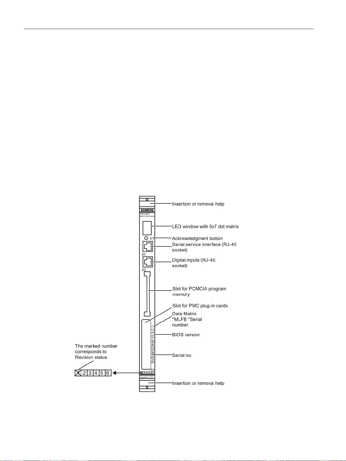
CPU modules
4.2.3
Control and display elements
LED display
Acknowledge button S1
ASI
Front panel
Aotewell Ltd
www.aotewell.com
Industry Automation
HongKong|UK|China
+86-755-8660-6182
4.2 CPU module CPU550/CPU551
The processor number, states and faults are displayed using a 5x7 dot matrix LED array.
This button has two functions:
● Clearing the fault display:
The acknowledge button can be used to clear sporadic or non-critical fault displays on the
5x7 dot matrix LED. An additional fault is displayed after the first one has been
acknowledged.
● Digital signal input can be evaluated using the
function block.
Figure 4-3 Front panel of CPU551
SIMATIC TDC hardware
90 System Manual, 08/2017, A5E01114865-AL
Page 91

CPU modules
4.2.4
Status and fault displays
Display
Operating and fault states
Can be
cleared with
S1
1... 20
User program is running
A User error
Diagnostics event, user-defined by means of USF function block
All 35 dots off
of consecutive numbers.
All 35 dots
flashing
0 Initialization error
treme left should first be selected.
b Monitoring error
Aotewell Ltd
www.aotewell.com
Industry Automation
HongKong|UK|China
+86-755-8660-6182
4.2 CPU module CPU550/CPU551
The configured number of the CPU module (1...20) is displayed in normal operation. Faults
are indicated by a letter that informs you of the type of fault.
Slow alternation between the lit and dark state of the 5x7 dot matrix LEDs is referred to as
flashing in the following table.
Table 4- 6 Operating and fault states of CPU550/CPU551
Configured number of the CPU module in normal operation.
User program is running
Initialization phase:
User program is not running
Individual initialization phases during startup are indicated by means
Module failure:
User program is not running
• Hardware failure => replace CPU550/CPU551
• Fatal software error => contact the Hotline
User program is not running
Diagnostics should start at the CPU module that was the first to dis-
play fault message “0”.
• Flashing "0" Faults on this module
• Permanent "0": Faults on a different module
If none of the CPU modules can be identified as having been the first
one, then of those which display a "0", the one inserted to the ex-
No
Yes
No
No
No
User program is running
Low-priority errors during initialization that allow the start of normal
operation and that are detected in the background process, e.g.: For
example,
• missing, low backup battery
• Missing program memory module
• Fan failure
• Invalid floating value (substitute value will be used)
SIMATIC TDC hardware
System Manual, 08/2017, A5E01114865-AL
Yes
91
Page 92

CPU modules
Display
Operating and fault states
Can be
cleared with
S1
C Communication error
ware, section "Diagnostics".
d User stop
Module is in STOP, triggered by this CPU itself.
Aotewell Ltd
www.aotewell.com
Industry Automation
HongKong|UK|China
+86-755-8660-6182
4.2 CPU module CPU550/CPU551
User program is running
Incorrect configuration of communication, or connection error
For more information on diagnostics functions, refer to the manual
"D7-SYS - STEP 7, CFC and SFC configuring", chapter Basic soft-
(not with CPU550)
User program is not running
User stop results in a stop of all CPUs in the same rack.
• Permanent "d":
Module is in STOP, triggered by another CPU.
• Flashing "d"
No
No
SIMATIC TDC hardware
92 System Manual, 08/2017, A5E01114865-AL
Page 93

CPU modules
Display
Operating and fault states
Can be
cleared with
S1
E Task Manager error
chapter Basic software, section "Diagnostics".
H System error
chapter Basic software, section "Diagnostics".
Aotewell Ltd
www.aotewell.com
Industry Automation
HongKong|UK|China
+86-755-8660-6182
4.2 CPU module CPU550/CPU551
User program is running
• Flashing "I": Initial error
• Static "I":
Sequential error after a lower priority error
The following errors are possible:
Cycle errors
•
A task could not be completed within the sampling time.
Task overflow
•
If a task that has not been not assigned top priority needs to be
restarted.
•
No free local buffer
The data buffer is no longer released. The task start will be
skipped.
•
Software time monitoring
If the basic sampling time is not processed four times in succession. The basic clock cycle timer is re-initialized with the configured basic sampling time and processing is continued.
For more information on diagnostics functions, refer to the manual
"D7-SYS - STEP 7, CFC and SFC configuring
(http://support.automation.siemens.com/WW/view/de/8776786/0/en)",
Yes
User program is not running
Hardware or software problems causing a program crash.
• Flashing "H" Faults on this module
• Permanent "H": Faults on a different module
For more information on diagnostics functions, refer to the manual
"D7-SYS - STEP 7, CFC and SFC configuring
(http://support.automation.siemens.com/WW/view/de/8776786/0/en)",
No
SIMATIC TDC hardware
System Manual, 08/2017, A5E01114865-AL
93
Page 94
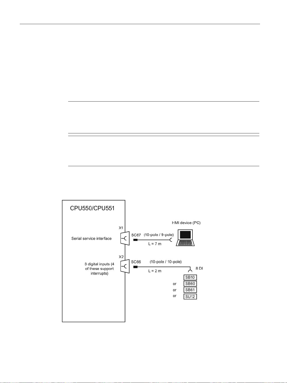
CPU modules
4.2.5
Application notes and immunity to interference
Note
For more information on fan operation, refer to chapter "
For more information on EMC and environmental conditions, refer to chapter "
technical specifications
Note
Shutdown behavior of various CPU modules
The various CPU modules exhibit slight time differences in their shutdown behavior when
the power supply is interrupted.
4.2.6
Connection options
Aotewell Ltd
www.aotewell.com
Industry Automation
HongKong|UK|China
+86-755-8660-6182
4.2 CPU module CPU550/CPU551
● Fan operation is necessary.
● Interference-proof operation is only possible if the CPU550/CPU551 is firmly attached to
the rack. Insert the module and then bolt it onto the rack accordingly (two screw heads,
see "Control and display elements (Page 90)").
● The module may not be inserted or removed while the rack is on live voltage.
● A CPU must be inserted into the first slot of the rack.
Rack (Page 39)".
General
(Page 37)".
Figure 4-4 Connection options of CPU550/CPU551
SIMATIC TDC hardware
94 System Manual, 08/2017, A5E01114865-AL
Page 95

CPU modules
4.2.7
Additional components
Component
Designation
Article number
Program memory (4 MB)
MC 500
6DD1610-0AH4
Program memory (2 MB)
MC 521
6DD1610-0AH3
(10-pole/10-pole)
Electrical 1:1 wiring, no signal conversion
version
version
Electrical 1:1 wiring, no signal conversion
4.2.8
Pin assignments
Serial service interface (X1)
X1
SC67
PIN
Designation
PIN CPU side
PIN PC side
1
DCD (Data Carrier Detect)
n.c.
n.c.
2
RxD (Receive Data)
2
3
3
TxD (Transmit Data)
3
2
4
DTR (Data Terminal Ready)
n.c.
n.c.
5
GND (Ground)
5
5
6
DSR (Data Set Ready)
n.c.
n.c.
7
RTS (Request to Send)
n.c.
n.c.
8
CTS (Clear to Send)
n.c.
n.c.
9
RI (Ring Indicator)
n.c.
n.c.
10
(n.c.) n.c.
Aotewell Ltd
www.aotewell.com
Industry Automation
HongKong|UK|China
+86-755-8660-6182
4.2 CPU module CPU550/CPU551
Table 4- 7 Additional components for CPU550/CPU551
Program memory (8 MB) MC 510 6DD1610-0AH6
PC connecting cable
(10-pole/9-pole)
Cable for digital inputs
Interface module
Interface module with electrical isolation and signal con-
Interface module with electrical isolation and signal con-
Interface module
An control or configuration PC is connected to the 10-pin RJ-45 socket with polarity reversal
protection using the SC67 PC cable.
SC67 6DD1684-0GH0
SC66 6DD1684-0GG0
SB10 6DD1681-0AE2
SB60 6DD1681-0AF4
SB61 6DD1681-0EB3
SU12 6DD1681-0AJ1
Table 4- 8 Pin assignment of X1 and cable SC67
n.c.: n.c.
SIMATIC TDC hardware
System Manual, 08/2017, A5E01114865-AL
95
Page 96

CPU modules
Digital inputs (X2)
X2
SC66
PIN
Designation
PIN CPU side
PIN PC side
1
Ground n.c.
n.c.
2
Digital input 0 (supports interrupts)
2
1
4
Digital input 2 (supports interrupts)
4
3
6
Digital input 4 6
5
7
Digital input 5 7
6
8
Digital input 6 8
7
9
Digital input 7 9
8
10
Ground 10
10
n.c.: n.c.
Aotewell Ltd
www.aotewell.com
Industry Automation
HongKong|UK|China
+86-755-8660-6182
4.2 CPU module CPU550/CPU551
An interface module is connected to the 10-pin RJ-45 socket with polarity reversal protection
via cable SC66.
Table 4- 9 Pin assignment X2 and cable SC66
3 Digital input 1 (supports interrupts) 3 2
5 Digital input 3 (supports interrupts) 5 4
SIMATIC TDC hardware
96 System Manual, 08/2017, A5E01114865-AL
Page 97

CPU modules
4.2.9
Technical specifications/performance features
Article number
CPU module CPU550
6DD1600-0BA0
6DD1600-0BA3
Note
Where two different values are specified for a feature (separated by "/") in the manual, the
first is valid for the module with article nu
module with article number 6DD1600
6DD1600
CPU
6DD1600-0BA1
6DD1600-0BA2
6DD1600-0BA3
Processor
64 bit RISC processor
Clock frequency
266 MHz
500 MHz
800 MHz
Aotewell Ltd
www.aotewell.com
Industry Automation
HongKong|UK|China
+86-755-8660-6182
4.2 CPU module CPU550/CPU551
CPU module CPU551 6DD1600-0BA1 /
6DD1600-0BA2 /
The CPU modules CPU551 with the article numbers 6DD1600-0BA1 and 6DD1600-0BA2
have been replaced by the modules with the article number 6DD1600-0BA3.
mber 6DD1600-0BA1 and the second for the
-0BA2 and the third for modules with the article number
-0BA3.
CPU
SIMATIC TDC hardware
System Manual, 08/2017, A5E01114865-AL
97
Page 98

CPU modules
Memory
6DD1600-0BA1
6DD1600-0BA2
6DD1600-0BA3
SAV
Synchronized L1 cache
64 KB
64 KB
64 KB
ext. L2 cache
int. L2 cache
512 KB
256 KB
512 KB
ext. L3 cache
int. L3 cache
Module slots
Number
3
PMC plug-in cards are currently not provided.
Time
Resolution
0.1 ms
Aotewell Ltd
www.aotewell.com
Industry Automation
HongKong|UK|China
+86-755-8660-6182
4.2 CPU module CPU550/CPU551
CPU
SDRAM / DDR2-DRAM
• During initialization, the user program is loaded from
program memory and expanded (Boot Flash is available
separately)
• Data memory for the operating system, communication,
message buffer, and Trace
SRAM
Buffered SRAM (by means of external battery in the rack)
contains the following data that must be backed up to retentive memory on power failure:
• Fault diagnostics of the operating system ("exception
buffer")
• Max. 993 process variables configured with
tion block
• Data recorded using the Trace function or the message
system (SRAM can be optionally configured)
Synchronized L2 cache
Synchronized L3 cache
func-
32 MB 128 MB 1 GB
256 KB
2 MB 8 MB 1 MB
512 KB 512 KB
Allocation of the slots
1)
• Program memory MC5xx
1)
• PMC plug-in cards
SIMATIC TDC hardware
98 System Manual, 08/2017, A5E01114865-AL
Page 99

CPU modules
Programming
Offline loading
Online download
User program size
Utilization
Program memory
Aotewell Ltd
www.aotewell.com
Industry Automation
HongKong|UK|China
+86-755-8660-6182
4.2 CPU module CPU550/CPU551
The user program executed on the CPU module is configured on a PC using
STEP7/HWConfig and CFC and then downloaded to program memory.
The program memory must be located in the CPU module slot provided.
There are two ways of loading the user program:
●
Carried out on the PC using an integrated or external PCMCIA programming adapter
("PC card").
●
Direct user program download from the PC to program memory in the CPU module via
serial service interface.
The size of the user program (compressed to approx. 50 %) that was downloaded to
program memory and the size of free program memory can be viewed in the CFC by
selecting the following menu command:
● PLC / Load / Info
Average load (measured with block PSL) should not exceed 95 %, since this may lead to
sporadic overload.
The user program created in CFC is downloaded to program memory. Program memory is
realized with Flash EPROM (2, 4 or 8 MB) and 8 KB EEPROM cache memory.
The following program memory may be used optionally, depending on the size of the user
program:
● MC500 (4 MB)
● MC510 (8 MB)
● MC521 (2 MB)
SIMATIC TDC hardware
System Manual, 08/2017, A5E01114865-AL
99
Page 100

CPU modules
Digital inputs
Number
8
Version
4 of the 8 digital inputs support interrupts
Electrical isolation
No
be triggered.)
Interfaces
Communication
Communication functions
Local CPU coupling
nels (independent of the protocol used)
Voltage, currents
Rated voltages at 25 °C
Typical current consumption
6DD1600-0BA2
+5 V
1.5 A
1.3 A
+3.3 V
2.0 A
1.7 A
+12 V
40 mA
20 mA
-12 V
40 mA
20 mA
Backup battery
2.2 / 3 µA
Aotewell Ltd
www.aotewell.com
Industry Automation
HongKong|UK|China
+86-755-8660-6182
4.2 CPU module CPU550/CPU551
Input voltage
• Rated voltage
• For 0 signal
• For 1 signal
Input current
• For 0 signal, normally
• For 1 signal, normally
Delay time per channel, max.
(Minimum cycle during which interrupt tasks can
Serial service interface (X1)
• Functions for the user program
– Testing and commissioning
– Loading the program
• Transmission rate
24 V
-1 V to +6 V
+13.5 V to +33 V
0 mA
3 mA
100 µs
RS232 interface (V.24)
with CFC or “Basic commissioning”
from the PC
19.2 Kbps
Max. number of configured send/receive chan-
1000
6DD1600-0BA1
SIMATIC TDC hardware
100 System Manual, 08/2017, A5E01114865-AL
6DD1600-0BA3
 Loading...