

Page 1
Page 2
___________________
___________________
___________
___________
___________
___________________
___________________
SIMATIC
S7-1500, ET 200MP, ET 200SP
Counting, measurement and
position detection
Function Manual
12/2017
A5E32009889
Preface
Documentation guide
1
The basics of counting,
measurement and position
detection
2
Using the
High_Speed_Counter
technology object
3
Using the
SSI_Absolute_Encoder
technology object
4
Using the module
5
Service & Support
A
-AG
Page 3
Siemens AG
Division Digital Factory
Postfach 48 48
90026 NÜRNBERG
GERMANY
A5E32009889-AG
Ⓟ
Copyright © Siemens AG 2017.
All rights reserved
Legal information
Warning notice system
DANGER
indicates that death or severe personal injury will result if proper precautions are not taken.
WARNING
indicates that death or severe personal injury may result if proper precautions are not taken.
CAUTION
indicates that minor personal injury can result if proper precautions are not taken.
NOTICE
indicates that property damage can result if proper precautions are not taken.
Qualified Personnel
personnel qualified
Proper use of Siemens products
WARNING
Siemens products may only be used for the applications described in the catalog and in the relevant technical
maintenance are required to ensure that the products operate safely and without any problems. The permissible
ambient conditions must be complied with. The information in the relevant documentation must be observed.
Trademarks
Disclaimer of Liability
This manual contains notices you have to observe in order to ensure your personal safety, as well as to prevent
damage to property. The notices referring to your personal safety are highlighted in the manual by a safety alert
symbol, notices referring only to property damage have no safety alert symbol. These notices shown below are
graded according to the degree of danger.
If more than one degree of danger is present, the warning notice representing the highest degree of danger will
be used. A notice warning of injury to persons with a safety alert symbol may also include a warning relating to
property damage.
The product/system described in this documentation may be operated only by
task in accordance with the relevant documentation, in particular its warning notices and safety instructions.
Qualified personnel are those who, based on their training and experience, are capable of identifying risks and
avoiding potential hazards when working with these products/systems.
Note the following:
documentation. If products and components from other manufacturers are used, these must be recommended
or approved by Siemens. Proper transport, storage, installation, assembly, commissioning, operation and
All names identified by ® are registered trademarks of Siemens AG. The remaining trademarks in this publication
may be trademarks whose use by third parties for their own purposes could violate the rights of the owner.
We have reviewed the contents of this publication to ensure consistency with the hardware and software
described. Since variance cannot be precluded entirely, we cannot guarantee full consistency. However, the
information in this publication is reviewed regularly and any necessary corrections are included in subsequent
editions.
for the specific
01/2018 Subject to change
Page 4

Preface
Purpose of the documentation
Basic knowledge required
Validity of the documentation
This documentation supports you in configuring and programming modules for counting and
measurement tasks of the S7-1500, ET 200MP and ET 200SP, as well as in position
feedback and position input.
The following knowledge is required in order to understand the documentation:
● General knowledge of automation technology
● Knowledge of the industrial automation system SIMATIC
● Knowledge about the use of Windows-based computers
● Proficiency with STEP 7
This documentation applies to the use of the following modules:
● S7-1500 modules
– TM Count 2x24V
– TM PosInput 2
– TM Timer DIDQ 16x24V
– CPU 1511C-1 PN
– CPU 1512C-1 PN
– DI 32x24VDC HF (as of firmware version V2.1.0)
– DI 16x24VDC HF (as of firmware version V2.1.0)
● ET 200SP modules
– TM Count 1x24V
– TM PosInput 1
– TM Timer DIDQ 10x24V
– DI 8x24VDC HS
TM Count, TM PosInput and compact CPU are suitable for complex counting and measuring
tasks and for position detection. TM Timer DIDQ and digital input modules are suitable for
simple counting tasks.
Counting, measurement and position detection
Function Manual, 12/2017, A5E32009889-AG
3
Page 5

Preface
Conventions
Note
The notes contain important information on the product described in the documentation, on
the ha
should be paid.
Additional assistance
Please observe notes marked as follows:
ndling of the product or on part of the documentation to which particular attention
● You can find information about the technical support offerings in the appendix Service &
Support (Page 199).
● The range of technical documentation for the individual SIMATIC products and
automation systems is available on the Internet
(http://www.siemens.com/simatic-tech-doku-portal).
● The online catalog and the ordering system are available on the Internet
(https://mall.industry.siemens.com).
Counting, measurement and position detection
4 Function Manual, 12/2017, A5E32009889-AG
Page 6

Table of contents
Preface ................................................................................................................................................... 3
1 Documentation guide .............................................................................................................................. 9
2 The basics of counting, measurement and position detection ................................................................ 14
2.1 Overview of modules and properties ...................................................................................... 14
2.2 Basics of counting, measuring and position input (TM Count, TM PosInput,
Compact CPU) ........................................................................................................................ 18
2.2.1 Convention .............................................................................................................................. 18
2.2.2 Overview of applications ......................................................................................................... 18
2.2.3 Recording of count signals ..................................................................................................... 22
2.2.3.1 Counting with incremental or pulse encoder .......................................................................... 22
2.2.3.2 Position input with SSI absolute encoder ............................................................................... 24
2.2.4 Behavior at the counting limits ................................................................................................ 25
2.2.5 Gate control with incremental or pulse encoder ..................................................................... 27
2.2.5.1 Software gate .......................................................................................................................... 27
2.2.5.2 Hardware gate ........................................................................................................................ 27
2.2.5.3 Internal gate ............................................................................................................................ 28
2.2.5.4 Counter behavior at gate start ................................................................................................ 29
2.2.6 Capture (Latch) ....................................................................................................................... 30
2.2.6.1 Capture with incremental or pulse encoder ............................................................................ 30
2.2.6.2 Capture with SSI absolute encoder ........................................................................................ 33
2.2.7 Synchronization ...................................................................................................................... 35
2.2.7.1 Synchronization by digital input .............................................................................................. 38
2.2.7.2 Synchronization at signal N .................................................................................................... 40
2.2.8 Comparison values ................................................................................................................. 43
2.2.8.1 Comparison values and outputs ............................................................................................. 43
2.2.8.2 Switching at comparison values with counter value as reference .......................................... 44
2.2.8.3 Switching at comparison values with position value (SSI absolute value) as reference ........ 48
2.2.8.4 Switching at comparison values with measured value as reference ...................................... 52
2.2.9 Measured value determination ............................................................................................... 54
2.2.9.1 Overview of measuring functions ............................................................................................ 54
2.2.9.2 Measured value determination with incremental or pulse encoder ........................................ 55
2.2.9.3 Measured value determination with SSI absolute encoder .................................................... 59
2.2.10 Hysteresis ............................................................................................................................... 62
2.2.10.1 Hysteresis with incremental or pulse encoder ........................................................................ 62
2.2.10.2 Hysteresis with SSI absolute encoder .................................................................................... 64
2.2.11 Interrupts ................................................................................................................................. 66
2.2.12 Position detection for Motion Control ...................................................................................... 66
2.2.13 Encoder signals ...................................................................................................................... 67
2.2.13.1 24 V and TTL count signals .................................................................................................... 67
2.2.13.2 RS422 count signals ............................................................................................................... 69
2.2.13.3 SSI signals .............................................................................................................................. 71
Counting, measurement and position detection
Function Manual, 12/2017, A5E32009889-AG
5
Page 7

Table of contents
3 Using the High_Speed_Counter technology object ................................................................................ 92
2.2.14 Signal evaluation of incremental signals ................................................................................ 72
2.2.14.1 Overview ................................................................................................................................ 72
2.2.14.2 Single evaluation .................................................................................................................... 72
2.2.14.3 Double evaluation .................................................................................................................. 73
2.2.14.4 Quadruple evaluation ............................................................................................................. 74
2.2.15 Clock synchronization (TM Count and TM PosInput) ............................................................ 75
2.3 Basics of counting (TM Timer DIDQ) ..................................................................................... 76
2.3.1 Overview of applications ........................................................................................................ 76
2.3.2 Counting with incremental encoder........................................................................................ 77
2.3.3 Counting with pulse encoder .................................................................................................. 78
2.3.4 24 V count signals .................................................................................................................. 79
2.3.5 Isochronous mode ................................................................................................................. 80
2.4 Basics of counting (digital input modules) ............................................................................. 81
2.4.1 Overview of applications ........................................................................................................ 81
2.4.2 Counting with pulse encoders ................................................................................................ 82
2.4.3 Behavior at the counting limits ............................................................................................... 83
2.4.4 Gate control ............................................................................................................................ 85
2.4.4.1 Software gate ......................................................................................................................... 85
2.4.4.2 Hardware gate........................................................................................................................ 85
2.4.4.3 Internal gate ........................................................................................................................... 86
2.4.5 Comparison values ................................................................................................................ 87
2.4.6 Interrupts ................................................................................................................................ 90
2.4.7 24 V count signals .................................................................................................................. 90
2.4.8 Isochronous mode ................................................................................................................. 91
3.1 Convention ............................................................................................................................. 92
3.2 High_Speed_Counter technology object ................................................................................ 92
3.3 Overview of the configuration steps ....................................................................................... 93
3.4 Add technology object ............................................................................................................ 94
3.5 Configuring the High_Speed_Counter ................................................................................... 96
3.5.1 Working with the configuration dialog .................................................................................... 96
3.5.2 Basic parameters ................................................................................................................... 98
3.5.3 Counter inputs (High_Speed_Counter) .................................................................................. 99
3.5.4 Counter behavior.................................................................................................................. 104
3.5.4.1 Counting limits and start value ............................................................................................. 104
3.5.4.2 Counter behavior at limits and gate start ............................................................................. 105
3.5.5 Behavior of a DI (High_Speed_Counter) ............................................................................. 106
3.5.6 Behavior of a DQ (High_Speed_Counter) ............................................................................ 110
3.5.7 Specify measured value (High_Speed_Counter) ................................................................. 115
3.6 Programming the High_Speed_Counter .............................................................................. 117
3.6.1 High_Speed_Counter instruction ......................................................................................... 117
3.6.2 Call instruction in the user program ..................................................................................... 118
3.6.3 Description High_Speed_Counter ........................................................................................ 119
3.6.4 High_Speed_Counter input parameters ............................................................................... 125
3.6.5 High_Speed_Counter output parameters ............................................................................ 126
3.6.6 Error codes of parameter ErrorID ........................................................................................ 128
3.6.7 High_Speed_Counter static variables .................................................................................. 130
Counting, measurement and position detection
6 Function Manual, 12/2017, A5E32009889-AG
Page 8

Table of contents
4 Using the SSI_Absolute_Encoder technology object ............................................................................ 136
5 Using the module ................................................................................................................................ 169
3.7 Commissioning the High_Speed_Counter ............................................................................ 132
3.7.1 Commissioning the technology object .................................................................................. 132
3.8 High_Speed_Counter diagnostics ......................................................................................... 134
3.8.1 Monitoring counter values, measured values, DIs and DQs ................................................ 134
4.1 Technology object SSI_Absolute_Encoder ........................................................................... 136
4.2 Overview of the configuration steps ...................................................................................... 137
4.3 Add technology object........................................................................................................... 138
4.4 Configuring SSI_Absolute_Encoder ...................................................................................... 140
4.4.1 Working with the configuration dialog ................................................................................... 140
4.4.2 Basic parameters .................................................................................................................. 141
4.4.3 SSI absolute encoder............................................................................................................ 142
4.4.4 Behavior of a DI (SSI_Absolute_Encoder) ............................................................................ 145
4.4.5 Behavior of a DQ (SSI_Absolute_Encoder) .......................................................................... 147
4.4.6 Specify measured value (SSI_Absolute_Encoder) ............................................................... 151
4.4.7 Examples of the frame format ............................................................................................... 153
4.5 Programming the SSI_Absolute_Encoder ............................................................................ 156
4.5.1 Instruction SSI_Absolute_Encoder ....................................................................................... 156
4.5.2 Call instruction in the user program ...................................................................................... 157
4.5.3 Description SSI_Absolute_Encoder ...................................................................................... 158
4.5.4 Input parameter SSI_Absolute_Encoder............................................................................... 161
4.5.5 Output parameter SSI_Absolute_Encoder ............................................................................ 162
4.5.6 Error codes of parameter ErrorID ......................................................................................... 164
4.5.7 Static tags SSI_Absolute_Encoder ....................................................................................... 165
4.6 Commissioning SSI_Absolute_Encoder ............................................................................... 166
4.6.1 Commissioning the technology object .................................................................................. 166
4.7 SSI_Absolute_Encoder diagnostics ...................................................................................... 167
4.7.1 Monitoring counter values, measured values, DIs and DQs ................................................ 167
5.1 Using the technology module ............................................................................................... 169
5.1.1 Convention ............................................................................................................................ 169
5.1.2 Configuring a module ............................................................................................................ 169
5.1.2.1 Adding a technology module for hardware configuration (TM Count and TM PosInput) ..... 169
5.1.2.2 Adding a technology module to hardware configuration (Compact CPU) ............................ 170
5.1.2.3 Parameter assignment options ............................................................................................. 171
5.1.2.4 Basic parameters .................................................................................................................. 172
5.1.2.5 Additional parameters for Compact CPU .............................................................................. 180
5.1.3 Parameter assignment of module ......................................................................................... 183
5.1.3.1 Parameter setting (hardware configuration) Opening (TM Count and TM PosInput) ........... 183
5.1.3.2 Parameter setting (hardware configuration) Opening (Compact CPU) ................................ 183
5.1.4 Online & diagnostics module ................................................................................................ 183
5.1.4.1 Displaying and evaluating diagnostics .................................................................................. 183
5.1.5 Control and feedback interface (TM Count, TM PosInput) ................................................... 185
5.1.5.1 Assignment of the control interface ...................................................................................... 185
5.1.5.2 Assignment of the feedback interface ................................................................................... 188
Counting, measurement and position detection
Function Manual, 12/2017, A5E32009889-AG
7
Page 9

Table of contents
A Service & Support ................................................................................................................................ 199
Index ................................................................................................................................................... 202
5.2 Using the digital input module .............................................................................................. 192
5.2.1 Configuring and assigning parameters to the module ......................................................... 192
5.2.1.1 Adding a module to the hardware configuration .................................................................. 192
5.2.1.2 Open hardware configuration ............................................................................................... 192
5.2.1.3 Counting operating mode ..................................................................................................... 193
5.2.2 Online & diagnostics module ............................................................................................... 198
5.2.2.1 Displaying and evaluating diagnostics ................................................................................. 198
Counting, measurement and position detection
8 Function Manual, 12/2017, A5E32009889-AG
Page 10
1
Basic information
Device information
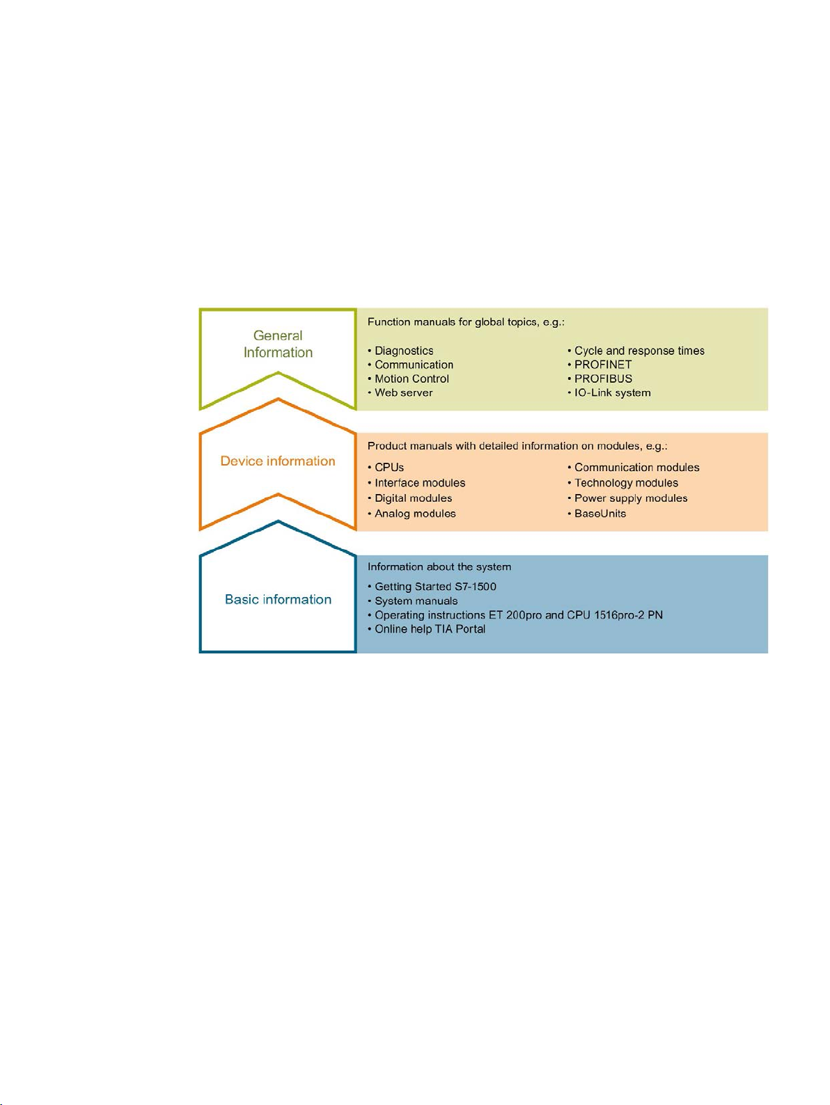
The documentation for the SIMATIC S7-1500 automation system, for CPU 1516pro-2 PN
based on SIMATIC S7-1500, and for the distributed I/O systems SIMATIC ET 200MP,
ET 200SP and ET 200AL is divided into three areas.
This division allows you easier access to the specific information you require.
System manuals and Getting Started manuals describe in detail the configuration,
installation, wiring and commissioning of the SIMATIC S7-1500, ET 200MP, ET 200SP and
ET 200AL systems; use the corresponding operating instructions for CPU 1516pro-2 PN.
The STEP 7 online help supports you in configuration and programming.
Product manuals contain a compact description of the module-specific information, such as
properties, terminal diagrams, characteristics and technical specifications.
Counting, measurement and position detection
Function Manual, 12/2017, A5E32009889-AG
9
Page 11

Documentation guide
General information
Manual Collections
"mySupport"
"mySupport" - Documentation
The function manuals contain detailed descriptions on general topics such as diagnostics,
communication, Motion Control, Web server, OPC UA.
You can download the documentation free of charge from the Internet
(http://w3.siemens.com/mcms/industrial-automation-systems-simatic/en/manual-
overview/Pages/Default.aspx).
Changes and additions to the manuals are documented in product information sheets.
You will find the product information on the Internet:
● S7-1500/ET 200MP (https://support.industry.siemens.com/cs/us/en/view/68052815)
● ET 200SP (https://support.industry.siemens.com/cs/us/en/view/73021864)
● ET 200AL (https://support.industry.siemens.com/cs/us/en/view/99494757)
The Manual Collections contain the complete documentation of the systems put together in
one file.
You will find the Manual Collections on the Internet:
● S7-1500/ET 200MP (https://support.industry.siemens.com/cs/ww/en/view/86140384)
● ET 200SP (https://support.industry.siemens.com/cs/ww/en/view/84133942)
● ET 200AL (https://support.industry.siemens.com/cs/ww/en/view/95242965)
With "mySupport", your personal workspace, you make the best out of your Industry Online
Support.
In "mySupport", you can save filters, favorites and tags, request CAx data and compile your
personal library in the Documentation area. In addition, your data is already filled out in
support requests and you can get an overview of your current requests at any time.
You must register once to use the full functionality of "mySupport".
You can find "mySupport" on the Internet (https://support.industry.siemens.com/My/ww/en).
In the Documentation area in "mySupport" you can combine entire manuals or only parts of
these to your own manual.
You can export the manual as PDF file or in a format that can be edited later.
You can find "mySupport" - Documentation on the Internet
(http://support.industry.siemens.com/My/ww/en/documentation).
Counting, measurement and position detection
10 Function Manual, 12/2017, A5E32009889-AG
Page 12

Documentation guide
"mySupport" - CAx data
Application examples
TIA Selection Tool
In the CAx data area in "mySupport", you can access the current product data for your CAx
or CAe system.
You configure your own download package with a few clicks.
In doing so you can select:
● Product images, 2D dimension drawings, 3D models, internal circuit diagrams, EPLAN
macro files
● Manuals, characteristics, operating manuals, certificates
● Product master data
You can find "mySupport" - CAx data on the Internet
(http://support.industry.siemens.com/my/ww/en/CAxOnline).
The application examples support you with various tools and examples for solving your
automation tasks. Solutions are shown in interplay with multiple components in the system separated from the focus on individual products.
You will find the application examples on the Internet
(https://support.industry.siemens.com/sc/ww/en/sc/2054).
With the TIA Selection Tool, you can select, configure and order devices for Totally
Integrated Automation (TIA).
This tool is the successor of the SIMATIC Selection Tool and combines the known
configurators for automation technology into one tool.
With the TIA Selection Tool, you can generate a complete order list from your product
selection or product configuration.
You can find the TIA Selection Tool on the Internet
(http://w3.siemens.com/mcms/topics/en/simatic/tia-selection-tool).
Counting, measurement and position detection
Function Manual, 12/2017, A5E32009889-AG
11
Page 13

Documentation guide
SIMATIC Automation Tool
PRONETA
You can use the SIMATIC Automation Tool to run commissioning and maintenance activities
simultaneously on different SIMATIC S7 stations as a bulk operation, independently of the
TIA Portal.
The SIMATIC automation tool provides a variety of functions:
● Scanning of a PROFINET/Ethernet plant network and identification of all connected
CPUs
● Address assignment (IP, subnet, gateway) and station name (PROFINET device) to a
CPU
● Transfer of the date and programming device/PC time converted to UTC time to the
module
● Program download to CPU
● Operating mode switchover RUN/STOP
● CPU localization by means of LED flashing
● Reading out CPU error information
● Reading of CPU diagnostic buffer
● Reset to factory settings
● Updating the firmware of the CPU and connected modules
You can find the SIMATIC Automation Tool on the Internet
(https://support.industry.siemens.com/cs/ww/en/view/98161300).
With SIEMENS PRONETA (PROFINET network analysis), you analyze the plant network
during commissioning. PRONETA features two core functions:
● The topology overview independently scans PROFINET and all connected components.
● The IO check is a fast test of the wiring and the module configuration of a plant.
You can find SIEMENS PRONETA on the Internet
(https://support.industry.siemens.com/cs/ww/en/view/67460624).
Counting, measurement and position detection
12 Function Manual, 12/2017, A5E32009889-AG
Page 14

Documentation guide
SINETPLAN
SINETPLAN, the Siemens Network Planner, supports you in planning automation systems
and networks based on PROFINET. The tool facilitates professional and predictive
dimensioning of your PROFINET installation as early as in the planning stage. In addition,
SINETPLAN supports you during network optimization and helps you to exploit network
resources optimally and to plan reserves. This helps to prevent problems in commissioning
or failures during productive operation even in advance of a planned operation. This
increases the availability of the production plant and helps improve operational safety.
The advantages at a glance
● Network optimization thanks to port-specific calculation of the network load
● Increased production availability thanks to online scan and verification of existing systems
● Transparency before commissioning through importing and simulation of existing STEP 7
projects
● Efficiency through securing existing investments in the long term and optimal exploitation
of resources
You can find SINETPLAN on the Internet (https://www.siemens.com/sinetplan).
Counting, measurement and position detection
Function Manual, 12/2017, A5E32009889-AG
13
Page 15

detection
2
2.1
Overview of modules and properties
Modules for the S7-1500 and ET 200MP systems
Property
S7-1500 / ET 200MP
Technology module
Digital input mod-
ule
Compact CPU
TM Count 2x24V
TM PosInput 2
TM Timer DIDQ
16x24V
DI 32x24VDC HF,
DI 16x24VDC HF
CPU 1511C-1
PN,
CPU 1512C-1 PN
ed/deactivated
frequency
(Page 72)
range
(Page 24)
connection
connection
(Page 71) connection
(Page 66)
The table below summarizes the performance features of the modules for counting,
measuring and position input for the S7-1500 and ET 200MP systems.
Number of counters 2 2 41 2 6
Use of counters can
be activat-
Maximum signal
Maximum count frequency for incremental encoders with
quadruple evaluation
Maximum counting
Maximum position
value range
RS422/TTL incremental and pulse
encoder (Page 69)
24 V incremental
encoder connection
24 V pulse encoder
— — X X X
200 kHz 1 MHz 50 kHz 1 kHz 100 kHz
800 kHz 4 MHz 200 kHz — 400 kHz
32 bits (Page 22) 32 bits (Page 22) 32 bits (Page 77) 32 bits (Page 82) 32 bits (Page 22)
— 31 bits — — —
— X — — —
X (Page 67) — X (Page 79) — X (Page 67)
X (Page 67) — X (Page 79) X (Page 90) X (Page 67)
SSI absolute encoder
Position input for
Motion Control
Counting, measurement and position detection
14 Function Manual, 12/2017, A5E32009889-AG
— X — — —
X X — — X
Page 16
The basics of counting, measurement and position detection
Property
S7-1500 / ET 200MP
Technology module
Digital input mod-
ule
Compact CPU
TM Count 2x24V
TM PosInput 2
TM Timer DIDQ
16x24V
DI 32x24VDC HF,
DI 16x24VDC HF
CPU 1511C-1
PN,
CPU 1512C-1 PN
5 V encoder supply
— X — — —
24 V encoder supply
X X X — X
counter
counter
counter
Hysteresis (Page 62)
X X — — X
Software gate
X (Page 27)
X (Page 27)
—
X (Page 85)
X (Page 27)
Hardware gate
X (Page 27)
X (Page 27)
—
—
X (Page 27)
(Latch) (Page 30)
(Page 35)
Comparison functions
X (Page 43)
X (Page 43)
—
X (Page 87)
X (Page 43)
(Page 54)
PROFINET
signals
support
digital inputs
1
ter. Other channel configurations do not allow any counter use.
2.1 Overview of modules and properties
Number of additional
digital inputs per
Number of physical
digital outputs per
Number of logical
digital outputs per
Capture function
Synchronization
Frequency, velocity
and period duration
measurement
Support for isochronous mode on
3 2 — — 2
2 2 — — 1
2 2 — 1 2
X X — — X
X X — — X
X X — — X
X (Page 75) X (Page 75) X (Page 80) X (Page 91) —
Support for diagnostic
X (Page 66) X (Page 66) — — X (Page 66)
interrupts for sensor
Hardware interrupt
Configurable filter for
X (Page 66) X (Page 66) — X (Page 90) X (Page 66)
X X — X X
count signals and
The number of available counters is dependent on the channel configuration. In order to use four counters, you must
choose the use of eight inputs in the channel configuration. If you choose the use of three inputs, you can use one coun-
Counting, measurement and position detection
Function Manual, 12/2017, A5E32009889-AG
15
Page 17

The basics of counting, measurement and position detection
Modules for the ET 200SP system
Property
ET 200SP
Technology module
Digital input module
TM Count 1x24V
TM PosInput 1
TM Timer DIDQ
10x24V
DI 8x24VDC HS
Number of counters
1 1 31
4
Maximum signal frequency
200 kHz
1 MHz
50 kHz
10 kHz
quadruple evaluation (Page 72)
Maximum counting range
32 bits (Page 22)
32 bits (Page 22)
32 bits (Page 77)
32 bits (Page 82)
(Page 24)
nection
connection
24 V pulse encoder connection
X (Page 67)
—
X (Page 79)
X (Page 90)
(Page 71) connection
trol (Page 66)
5 V encoder supply
— — —
—
24 V encoder supply
X X X
X
inputs per counter
puts per counter
Hysteresis X X — —
Software gate
X (Page 27)
X (Page 27)
—
X (Page 85)
Hardware gate
X (Page 27)
X (Page 27)
—
X (Page 85)
(Page 30)
Synchronization (Page 35)
X X —
—
Comparison functions
X (Page 43)
X (Page 43)
—
X (Page 87)
(Page 54)
2.1 Overview of modules and properties
The following table provides an overview of the performance features of the modules for
counting, measuring and position input for the ET 200SP system.
Use of counters can be activated/deactivated
Maximum count frequency for
incremental encoders with
Maximum position value range
RS422/TTL incremental and
pulse encoder (Page 69) con-
24 V incremental encoder
SSI absolute encoder
Position input for Motion Con-
Number of additional digital
— — X X
800 kHz 4 MHz 200 kHz —
— 31 bits — —
— X — —
X (Page 67) — X (Page 79) —
— X — —
X X — —
3 2 — 1
Number of physical digital
outputs per counter
Number of logical digital out-
Capture function (Latch)
Frequency, velocity and period
duration measurement
Counting, measurement and position detection
16 Function Manual, 12/2017, A5E32009889-AG
2 2 — —
2 2 — 1
X X — —
X X — —
Page 18
The basics of counting, measurement and position detection
Property
ET 200SP
Technology module
Digital input module
TM Count 1x24V
TM PosInput 1
TM Timer DIDQ
10x24V
DI 8x24VDC HS
on PROFINET
Hardware interrupt support
X (Page 66)
X (Page 66)
—
—
signals and digital inputs
1
One counter for incremental encoder (A, B phase-shifted) and two counters for pulse encoder
2.1 Overview of modules and properties
Support for isochronous mode
Support for diagnostic interrupts for sensor signals
Configurable filter for count
X (Page 75) X (Page 75) X (Page 80) X (Page 91)
X (Page 66) X (Page 66) — —
X X — X
Counting, measurement and position detection
Function Manual, 12/2017, A5E32009889-AG
17
Page 19

The basics of counting, measurement and position detection
2.2
Basics of counting, measuring and position input (TM Count,
TM PosInput, Compact CPU)
2.2.1
Convention
Technology module
2.2.2
Overview of applications
Introduction
System environment for TM Count and TM PosInput
Application scenarios
Components required
Configuration software
In the user program
object
2.2 Basics of counting, measuring and position input (TM Count, TM PosInput, Compact CPU)
: We use the term "technology module" in this documentation both for the
technology modules TM Count and TM PosInput and the technology component of the
compact CPUs.
The technology module is configured and assigned parameters using the configuration
software.
The technology module functions are controlled and monitored via the user program.
The technology modules can be used in the following system environments:
Central operation with a
S7-1500 CPU or ET 200SP
CPU
• S7-1500 Automation
System or ET 200SP Distributed I/O System
• Technology module
STEP 7 (TIA Portal):
Operating with "Counting
and measurement" technology object
• Device configuration with
hardware configuration
• Parameter setting with
technology object
Counting and measurement
functions:
High_Speed_Counter instruction for the technology
object
Position input with SSI absolute encoder:
SSI_Absolute_Encoder instruction for the technology
Counting, measurement and position detection
18 Function Manual, 12/2017, A5E32009889-AG
STEP 7 (TIA Portal):
Position input for "Mo-
tion Control" technology
object
• Device configuration with
hardware configuration
• Parameter setting with
axis technology object
Instructions for "Motion Control" technology object
Page 20

The basics of counting, measurement and position detection
Application scenarios
Components required
Configuration software
In the user program
object
parameter settings with HSP
2.2 Basics of counting, measuring and position input (TM Count, TM PosInput, Compact CPU)
Central operation with a
S7-1500 CPU or ET 200SP
CPU
Distributed operation with a
S7-1500 CPU
Distributed operation with a
CPU S7-300/400 or S7-1200
• S7-1500 automation
system
• ET 200 distributed I/O
system
• Technology module
• S7-300/400 automation
system
• ET 200 distributed I/O
system
• Technology module
STEP 7 (TIA Portal):
Manual operation (without
technology object)
• Device configuration and
parameter setting with
hardware configuration
STEP 7 (TIA Portal):
Operating with "Counting
and measurement" technology object
• Device configuration with
hardware configuration
• Parameter setting with
technology object
STEP 7 (TIA Portal):
Position input for "Mo-
tion Control" technology
object
• Device configuration with
hardware configuration
• Parameter setting with
axis technology object
STEP 7 (TIA Portal):
Manual operation (without
technology object)
• Device configuration and
parameter setting with
hardware configuration
STEP 7 (TIA Portal):
Device configuration and
parameter setting with hardware configuration
STEP 7:
Device configuration and
Direct access to control and
feedback interface of the
technology module in the I/O
data
Counting and measuring
functions:
High_Speed_Counter instruction for the technology
object
Position input with SSI absolute encoder:
SSI_Absolute_Encoder instruction for the technology
Instructions for "Motion Control" technology object
Direct access to technology
module control and feedback
interface in the I/O data
Direct access to technology
module control and feedback
interface in the I/O data
Distributed operation in a
third-party system
Counting, measurement and position detection
Function Manual, 12/2017, A5E32009889-AG
• Third-party automation
system
• ET 200 distributed I/O
system
• Technology module
Third-party configuration
software:
Device configuration and
parameter settings with GSD
file
Direct access to technology
module control and feedback
interface in the I/O data
19
Page 21

The basics of counting, measurement and position detection
System environment for a Compact CPU
Application scenarios
Components required
Configuration software
In the user program
Parameter assignment options
2.2 Basics of counting, measuring and position input (TM Count, TM PosInput, Compact CPU)
The Compact CPUs can be used in the following system environments:
Central operation with a
S7-1500 Compact CPU
• S7-1500 automation
system
• Compact CPU
STEP 7 (TIA Portal):
Operating with "Counting
and measurement" technology object
• Device configuration with
hardware configuration
• Parameter settings with
High_Speed_Counter
technology object
STEP 7 (TIA Portal):
Position input for "Mo-
tion Control" technology
object
• Device configuration with
hardware configuration
• Parameter setting with
axis technology object
STEP 7 (TIA Portal):
Manual operation (without
technology object)
• Device configuration and
parameter setting with
hardware configuration
Counting and measuring
functions:
High_Speed_Counter instruction for the technology
object
Instructions for "Motion Control" technology object
Direct access to control and
feedback interface of the
technology module in the I/O
data
In an S7-1500 system, you have two options for parameter assignment and control of
technology module functions:
● Configuration using the technology object and control using the associated instruction
Access to the control and feedback interface of the technology module takes place
through the technology object.
● Parameter setting via hardware configuration
The control and feedback interface of the technology module is accessed using direct
access to the I/O data.
Counting, measurement and position detection
20 Function Manual, 12/2017, A5E32009889-AG
Page 22

2.2 Basics of counting, measuring and position input (TM Count, TM PosInput, Compact CPU)
Configuration via technology object
Parameter setting via hardware configuration
For central and distributed use, we recommend the convenient, graphics-assisted
configuration using a technology object. A detailed description of this configuration can be
found starting from section High_Speed_Counter technology object (Page 92).
You specify the "Operation with technology object "Counting and measuring"" in the device
configuration of the technology module: see section Operating mode (Page 174).
You can assign the technology module and counting channel in the basic parameters of the
technology object: see section Basic parameters (Page 98).
You specify the "Manual operation (without technology object)" in the device configuration of
the technology module: see section Operating mode (Page 174).
Additional support for parameter setting via hardware configuration is available in the
context-sensitive help for the parameters in STEP 7 (TIA Portal). A description of the control
and feedback interface is available in the following sections:
The basics of counting, measurement and position detection
Assignment of the control interface (Page 185)
Assignment of the feedback interface (Page 188)
Counting, measurement and position detection
Function Manual, 12/2017, A5E32009889-AG
21
Page 23

The basics of counting, measurement and position detection
2.2.3
Recording of count signals
2.2.3.1
Counting with incremental or pulse encoder
Counter limits
Start value
Gate control
2.2 Basics of counting, measuring and position input (TM Count, TM PosInput, Compact CPU)
Counting refers to the recording and adding up of events. The counters of the technology
modules capture and evaluate pulse and incremental signals. The count direction can be
specified using encoder or pulse signals or through the user program.
You can control counting processes using the digital inputs of the technology module. You
can switch the digital outputs exactly at defined counter values, regardless of the user
program.
You can configure the response of the counters using the functionalities described below.
The counter limits define the counter value range used. The counter limits are configurable
and can be modified during runtime using the user program.
The highest counter limit that can be set is 2147483647 (2
can be set is –2147483648 (–2
You can configure the response of the counter at the counter limits:
● Continue or stop counting upon violation of a counter limit (automatic gate stop)
● Set counter value to start value or to opposite counter limit upon violation of a counter
limit
31
).
31
–1). The lowest counter limit that
You can configure a start value within the counter limits. The start value can be modified
during runtime by the user program.
The technology module can, as configured, set the current counter value to the start value
upon synchronization, upon Capture function activation, upon violation of a counter limit or
when the gate is opened.
Opening and closing the hardware gate and software gate defines the period of time during
which the counting signals are captured.
The hardware gate is controlled externally via a digital input of the technology module. The
software gate is controlled via the user program. The hardware gate can be enabled through
parameter assignment. The software gate (bit in the control interface of the cyclic I/O data)
cannot be disabled.
Counting, measurement and position detection
22 Function Manual, 12/2017, A5E32009889-AG
Page 24

The basics of counting, measurement and position detection
Capture (Latch)
Synchronization
Hysteresis
2.2 Basics of counting, measuring and position input (TM Count, TM PosInput, Compact CPU)
You can configure an external reference signal edge that triggers the saving of the current
counter value or position value as a Capture value. The following external signals can trigger
the Capture function:
● Rising or falling edge of a digital input
● Both edges of a digital input
● Rising edge of the N signal at the encoder input
When using a digital input, you can specify whether counting is to continue from the current
counter value or from the start value after the Capture function.
You can configure an external reference signal edge to load the counter with the specified
start value. The following external signals can load the counter with the start value:
● Rising or falling edge of a digital input
● Rising edge of signal N at the encoder input
● Rising edge of signal N at the encoder input depending on the level of the assigned
digital input
You can specify hysteresis for the comparison values, within which a digital output is
prevented from switching again. An encoder can come to a standstill at a specific position,
and slight movements may make the counter value fluctuate around this position. If a
comparison value or a counting limit lies within this fluctuation range, the corresponding
digital output will be switched on and off with corresponding frequency if hysteresis is not
used. The hysteresis prevents these unwanted switching operations.
Counting, measurement and position detection
Function Manual, 12/2017, A5E32009889-AG
23
Page 25

The basics of counting, measurement and position detection
2.2.3.2
Position input with SSI absolute encoder
Description
Gray-dual conversion
Capture (Latch)
Hysteresis
Range for position value
Complete SSI frame
2.2 Basics of counting, measuring and position input (TM Count, TM PosInput, Compact CPU)
You can use the TM PosInput technology modules with an SSI absolute encoder for position
detection. The technology module reads the position value via a synchronous serial interface
from the SSI absolute encoder and makes it available to the controller.
You can switch the digital outputs of the technology module exactly at defined position
values, regardless of the user program. Position input with an SSI absolute encoder does not
involve gate control. Due to system constraints, synchronization is not possible with an SSI
absolute encoder.
Gray-code and dual-code SSI absolute encoders are supported.
You can configure one or both edges of a digital input that triggers a saving of the current
position value as Capture value.
You can specify hysteresis for the comparison values, within which a digital output is
prevented from switching again. An encoder can come to a standstill at a specific position,
and slight movements may make the position value fluctuate around this position. If a
comparison value or a limit lies within this fluctuation range, the corresponding digital output
is switched on and off with corresponding frequency if hysteresis is not used. The hysteresis
prevents these unwanted switching operations.
You can specify a frame length of 10 bits to 40 bits for the SSI absolute encoder. The
configurable bit numbers of the LSB and the MSB of the position value in the frame define
the value range. The technology module can read a position value with a maximum length
of31 bits and communicate it to the controller. The position value is treated as unsigned
positive value and can assume values between 0" and "2
Instead of having a measured variable returned, you can choose to have the least significant
32 bits of the current unprocessed SSI frame returned. This provides you with encoderspecific additional bits, such as error bits, in addition to the position value. If the SSI frame is
shorter than 32 bits, the complete SSI frame is returned right-aligned and the top unused bits
are returned with "0" in the feedback interface.
(MSB-LSB+1)-1
".
Counting, measurement and position detection
24 Function Manual, 12/2017, A5E32009889-AG
Page 26
The basics of counting, measurement and position detection
2.2.4
Behavior at the counting limits
Violation of a counting limit
Counting limit violated
Status bit
High counting limit
EVENT_OFLW is set
Note
The high counting limit and the start value define the value range of the counter:
Value range of the counter = (high limit
Examples
2.2 Basics of counting, measuring and position input (TM Count, TM PosInput, Compact CPU)
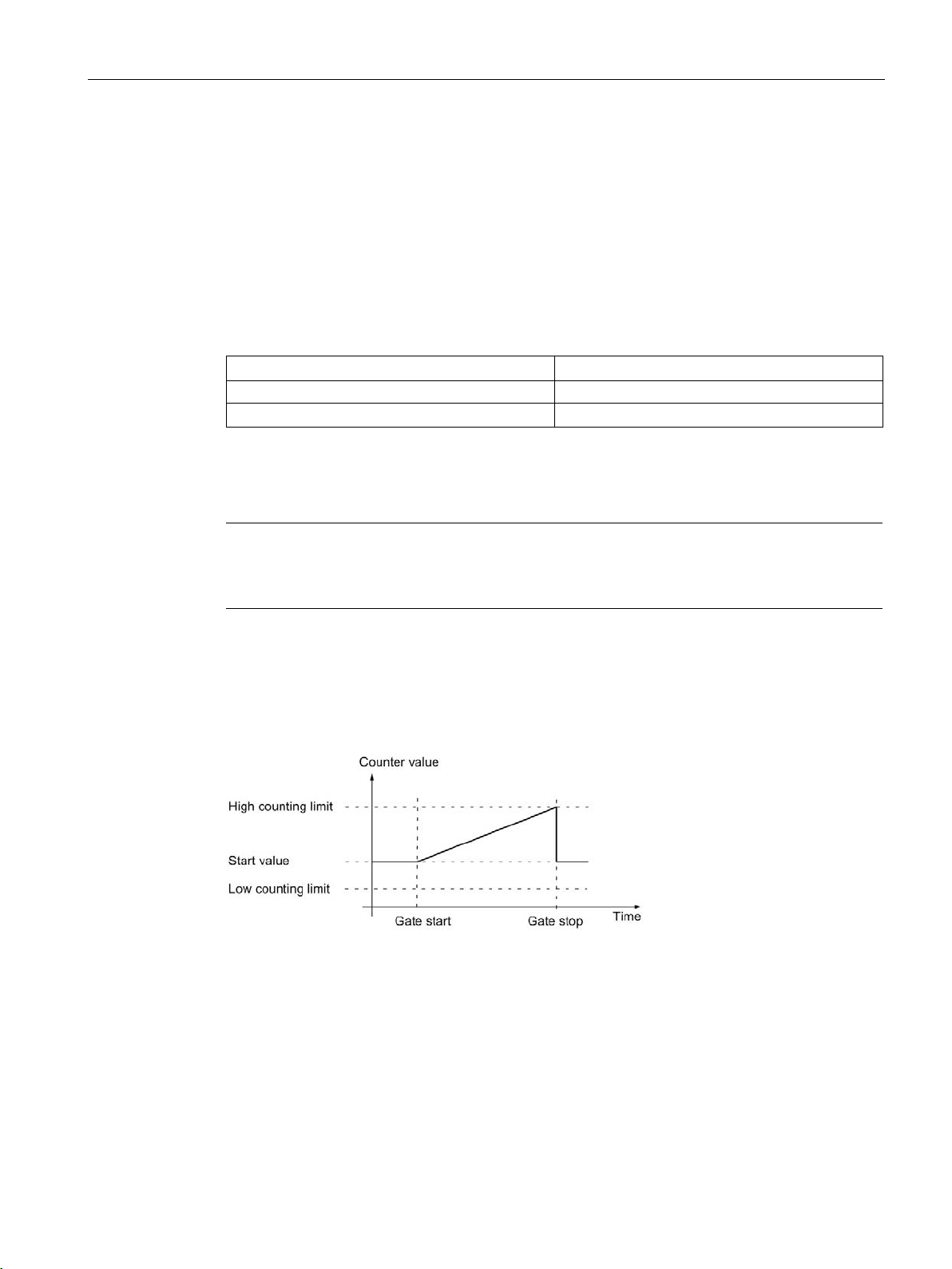
The high counting limit is violated when the current counter value is equal to the high
counting limit and another upward count pulse is received. The counter low limit is violated
when the current counter value is equal to the counter low limit and another downward count
pulse is received.
The appropriate status bit is set in the feedback interface in the event of limit violation:
Low counting limit EVENT_UFLW is set
You can reset the status bits with RES_EVENT .
You can configure whether or not and from which counter value counting is to continue
following counting limit violation.
– start value) + 1
The figure below shows an example for terminating the counting process (automatic gate
stop) after an overflow and setting the counter to the start value:
Counting, measurement and position detection
Function Manual, 12/2017, A5E32009889-AG
25
Page 27
The basics of counting, measurement and position detection
2.2 Basics of counting, measuring and position input (TM Count, TM PosInput, Compact CPU)
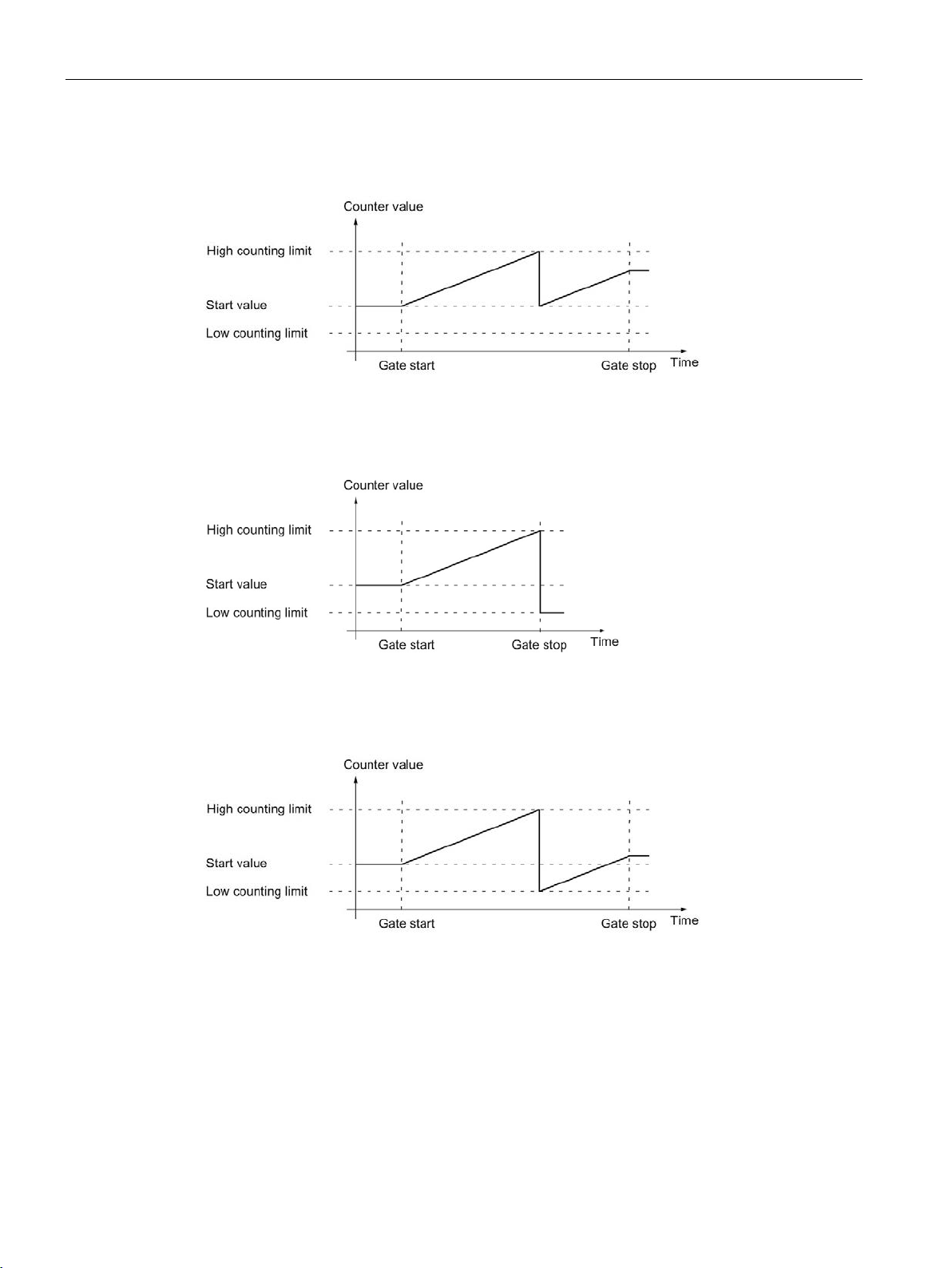
The figure below shows an example for continuing the counting process after an overflow
and setting the counter to the start value:
The figure below shows an example for terminating counting after an overflow and setting
the counter to the opposite counting limit:
The figure below shows an example for continuing the counting process after an overflow
and setting the counter to the opposite counting limit:
Counting, measurement and position detection
26 Function Manual, 12/2017, A5E32009889-AG
Page 28
The basics of counting, measurement and position detection
2.2.5
Gate control with incremental or pulse encoder
2.2.5.1
Software gate
2.2.5.2
Hardware gate
Note
The configured input filters delay the
Level-triggered opening and closing of the hardware gate with a digital input
2.2 Basics of counting, measuring and position input (TM Count, TM PosInput, Compact CPU)
Many applications require counting processes to be started or stopped in accordance with
other events. In such cases, counting is started and stopped using the gate function.
The technology modules have two gates for each channel. These define the resulting
internal gate:
● Software gate
● Hardware gate
The software gate of the channel is opened and closed with the control bit (Page 185)
SW_GATE. The status of the software gate is indicated by the feedback bit (Page 188)
STS_SW_GATE .
The hardware gate is optional. You open and close the hardware gate by means of signals
at the configured digital inputs of the channel.
control signal of the digital input.
The status of a DIm digital input is indicated by the respective feedback bit (Page 188)
STS_DIm .
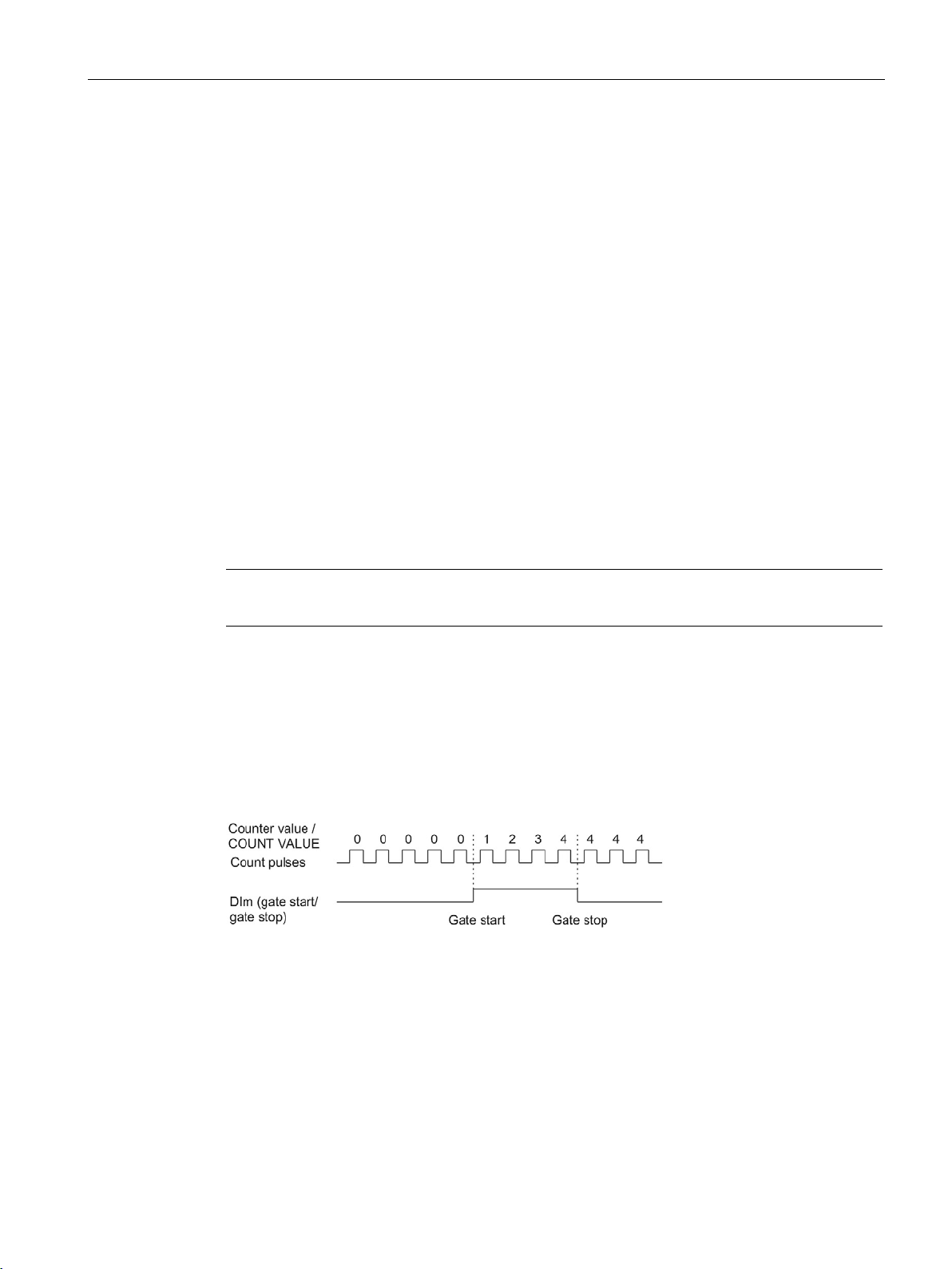
The figure below shows an example of level-triggered opening and closing with a digital
input. The digital input is configured to be active with high level:
As long as the digital input is active, the hardware gate is open and the count pulses are
counted. The hardware gate is closed when the digital input becomes inactive. The counter
value stays constant and ignores any further count pulses.
Counting, measurement and position detection
Function Manual, 12/2017, A5E32009889-AG
27
Page 29
The basics of counting, measurement and position detection
Edge-triggered opening and closing of the hardware gate with two digital inputs
2.2.5.3
Internal gate
Internal gate
Hardware gate
Software gate
Internal gate
Open/not configured
open
open
Open/not configured
closed
closed
closed
open
closed
2.2 Basics of counting, measuring and position input (TM Count, TM PosInput, Compact CPU)
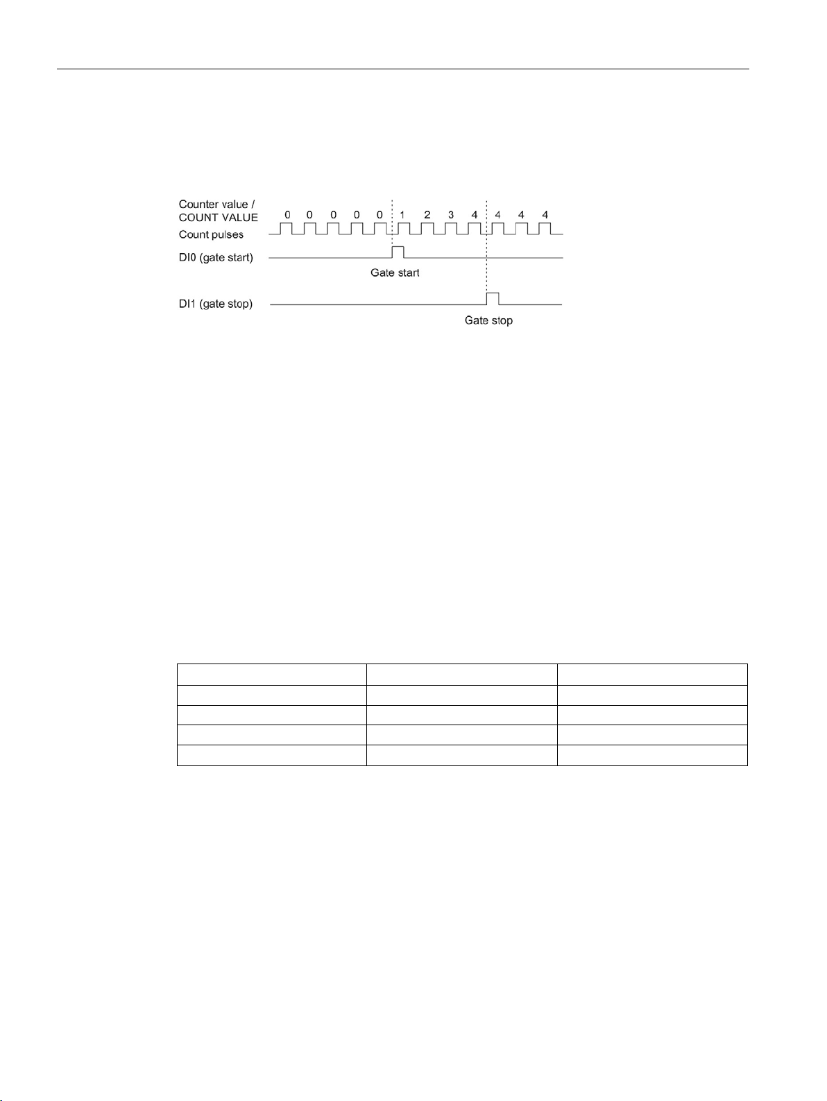
The figure below shows an example of opening and closing with two digital inputs. The two
digital inputs are configured so that the rising edge of the hardware gate opens:
The hardware gate is opened with the configured edge at the digital input that is configured
for opening. The hardware gate is closed with the configured edge at the digital input that is
configured for closing.
The internal gate is open if the software gate is open and the hardware gate is open or has
not been configured. The status of the internal gate is indicated by the feedback bit
(Page 188) STS_GATE.
If the internal gate is open, counting is started. If the internal gate is closed, all other count
pulses are ignored and counting is stopped.
If you want to control a counting process with the hardware gate only, the software gate must
be open. If you do not configure a hardware gate, the hardware gate is considered to be
always open. In this case, you open and close the internal gate with the software gate only.
closed closed closed
When you configure the counter behavior, you can specify whether the counting process is
to start from the start value or from the current counter value when the internal gate is
opened.
Counting, measurement and position detection
28 Function Manual, 12/2017, A5E32009889-AG
The internal gate can also be automatically closed upon violation of a counting limit. The
software or hardware gate must then be closed and reopened to continue counting.
Page 30

The basics of counting, measurement and position detection
2.2.5.4
Counter behavior at gate start
Setting counter to start value
Continuing with the current counter value
2.2 Basics of counting, measuring and position input (TM Count, TM PosInput, Compact CPU)
You have the following configuration options for counter behavior upon gate start:
● Setting counter to start value
● Continuing with the current counter value
Counter behavior is as follows for this configuration:
Each counting process starts with the start value when the internal gate is opened.
The figure below shows an example for continuing the counting process after counter is set
to the start value:
Counter behavior is as follows for this configuration:
Each counting process starts from the current counter value after the internal gate is
reopened.
The figure below shows an example for continuing the counting process with the current
counter value:
Counting, measurement and position detection
Function Manual, 12/2017, A5E32009889-AG
29
Page 31
The basics of counting, measurement and position detection
2.2.6
Capture (Latch)
2.2.6.1
Capture with incremental or pulse encoder
Description
Function principle
2.2 Basics of counting, measuring and position input (TM Count, TM PosInput, Compact CPU)
The "Capture" function is used to save the current counter value with an external reference
signal. You can configure the Capture function for the following reference signals:
● Rising or falling edge at a digital input
● Rising and falling edge at a digital input
● Rising edge of signal N at the encoder input
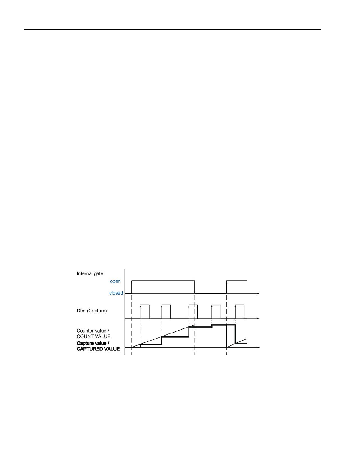
The Capture value is always the exact counter value at the time of the edge in question
(delayed by the configured input filter time). The Capture function is effective regardless of
the status of the internal gate. The unchanged counter value is saved when the gate is
closed.
The figure below shows an example of the Capture function with the following configuration:
● Start value = 0
● Capture event upon rising edge at configured digital input
● Set counter to start value at gate start
● Continue counting after Capture event
Counting, measurement and position detection
30 Function Manual, 12/2017, A5E32009889-AG
Page 32
The basics of counting, measurement and position detection
Note
The configured input filters delay the control signal of the corresponding digital input
The Capture function has no effect on the feedback bit STS_CNT and the LEDs UP and DN.
2.2 Basics of counting, measuring and position input (TM Count, TM PosInput, Compact CPU)
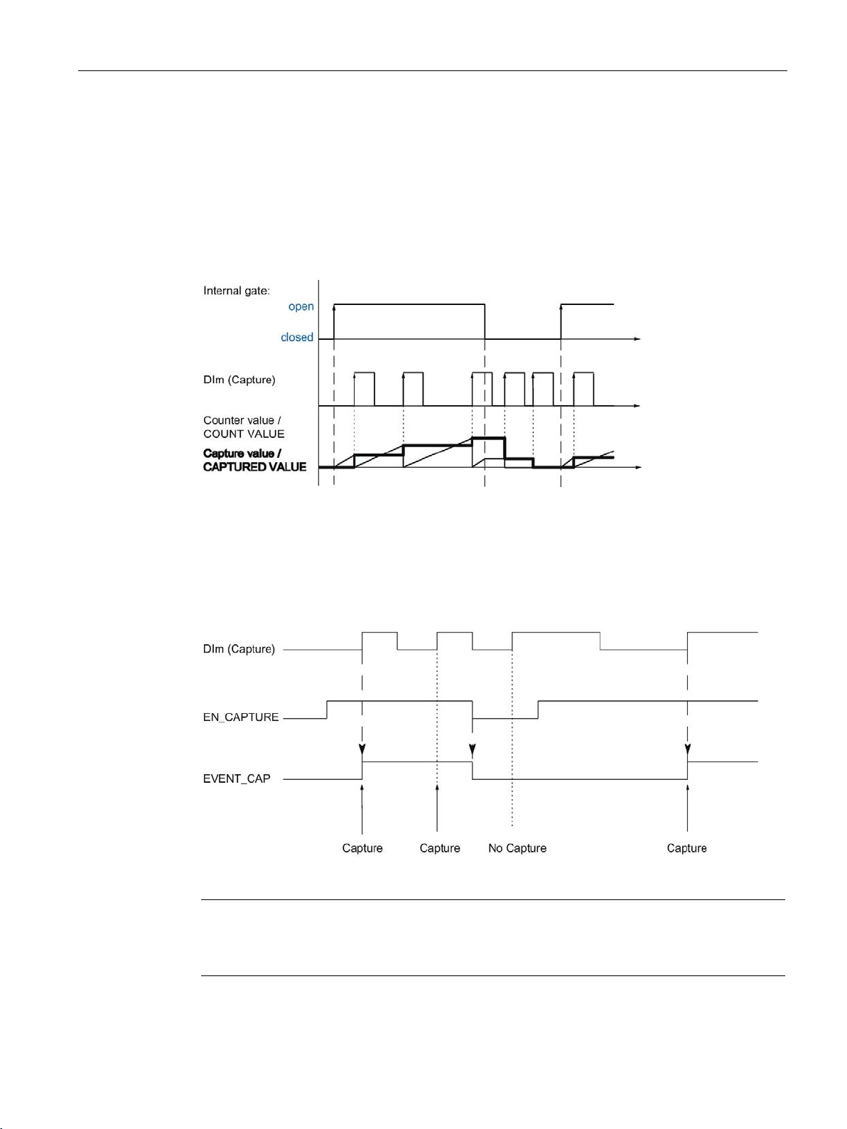
The figure below shows another example of the Capture function with the following
configuration:
● Start value = 0
● Capture event upon rising edge at configured digital input
● Set counter to start value at gate start
● Reset counter value to start value after Capture event and continue counting.
The control bit (Page 185) EN_CAPTURE is used to enable the Capture function. The
feedback bit (Page 188) EVENT_CAP indicates that a counter value has been saved as a
Capture in the feedback interface. If you reset EN_CAPTURE, EVENT_CAP is also reset.
The status of a digital input is indicated by the respective feedback bit (Page 188) STS_DIm .
The figure below shows an example of the EN_CAPTURE and EVENT_CAP bits with use of
the Capture function by the rising edge at a digital input:
Counting, measurement and position detection
Function Manual, 12/2017, A5E32009889-AG
.
31
Page 33

The basics of counting, measurement and position detection
Hardware interrupt
2.2 Basics of counting, measuring and position input (TM Count, TM PosInput, Compact CPU)
You can configure a hardware interrupt for the Capture function. Individual hardware
interrupts may be lost if the hardware interrupt rate is higher than the system
acknowledgement rate. You can signal a lost hardware interrupt with a diagnostic interrupt.
Counting, measurement and position detection
32 Function Manual, 12/2017, A5E32009889-AG
Page 34
The basics of counting, measurement and position detection
2.2.6.2
Capture with SSI absolute encoder
Description
Function principle
2.2 Basics of counting, measuring and position input (TM Count, TM PosInput, Compact CPU)
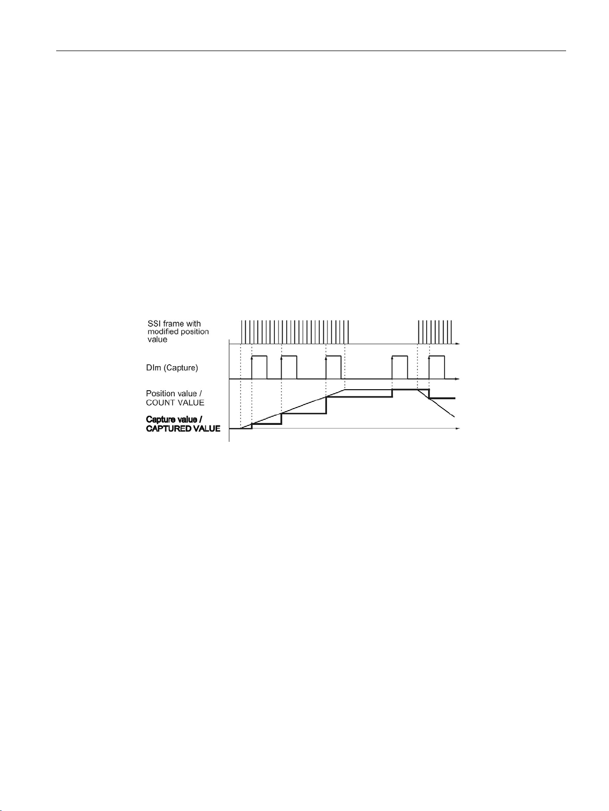
The "Capture" function is used to save the current position value using an external reference
signal. You can configure the Capture function for the following reference signals:
● Rising or falling edge at a digital input
● Rising and falling edge at a digital input
At the time of each edge, the position value of the last valid SSI frame is stored in the
Capture value.
The figure below shows an example of the Capture event by a rising edge at the configured
digital input:
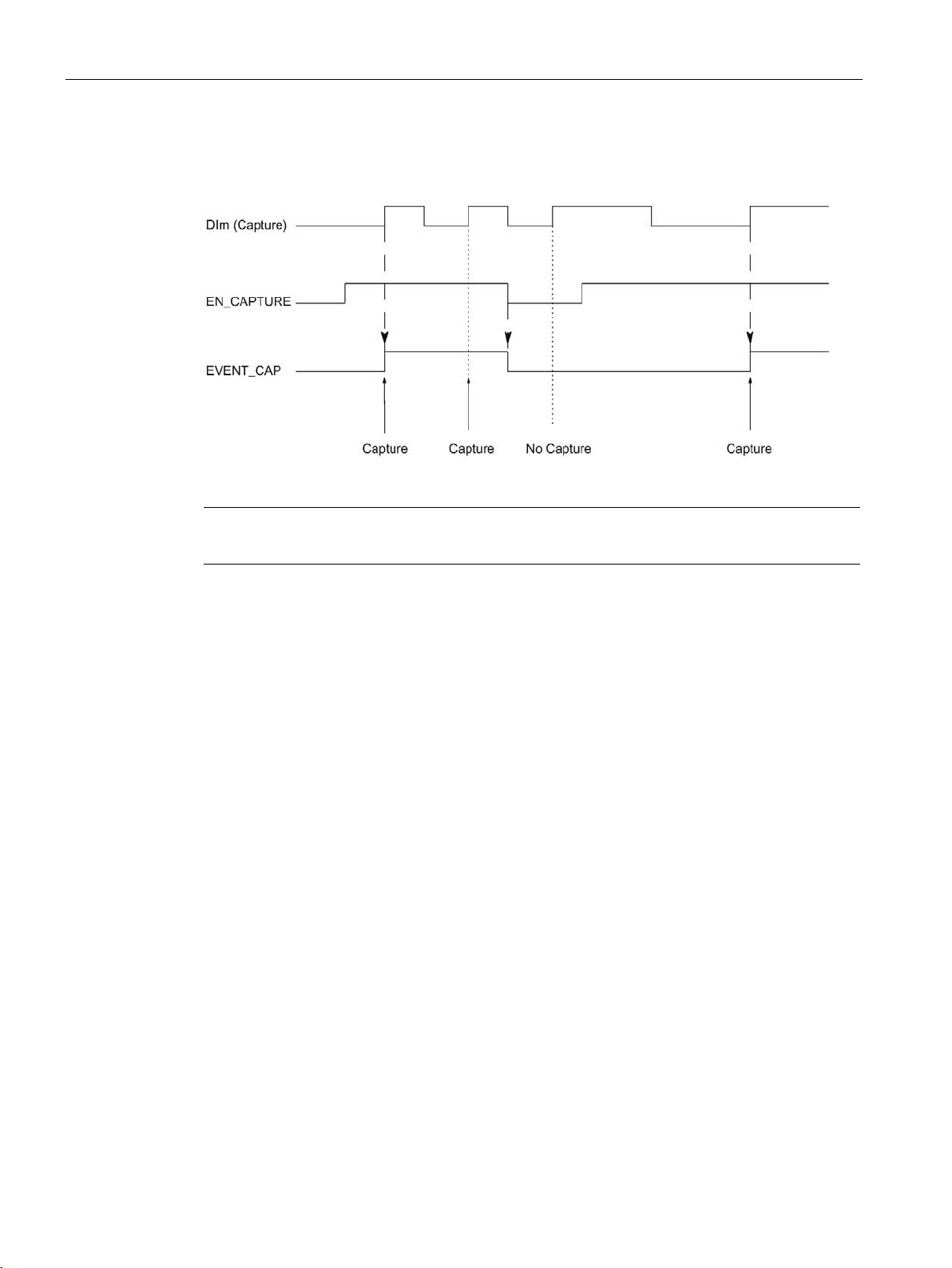
The control bit (Page 185) EN_CAPTURE is used to enable the Capture function. The
feedback bit (Page 188) EVENT_CAP indicates that a position value has been saved as
Capture value in the feedback interface. If you reset EN_CAPTURE, EVENT_CAP is also
reset. The status of a digital input is indicated by the respective feedback bit (Page 188)
STS_DIm .
Counting, measurement and position detection
Function Manual, 12/2017, A5E32009889-AG
33
Page 35
The basics of counting, measurement and position detection
Note
The config
Hardware interrupt
2.2 Basics of counting, measuring and position input (TM Count, TM PosInput, Compact CPU)
The figure below shows an example of the EN_CAPTURE and EVENT_CAP bits with use of
the Capture function by the rising edge at a digital input:
You can configure a hardware interrupt for the Capture function. Individual hardware
interrupts may be lost if the hardware interrupt rate is higher than the system
acknowledgement rate. You can signal a lost hardware interrupt with a diagnostic interrupt.
ured input filters delay the control signal of the corresponding digital input.
Counting, measurement and position detection
34 Function Manual, 12/2017, A5E32009889-AG
Page 36

The basics of counting, measurement and position detection
2.2.7
Synchronization
Description
Function principle
Note
The configured input filters delay the control signal of the corresponding digital input.
Synchronization has no effect on the
and DN.
2.2 Basics of counting, measuring and position input (TM Count, TM PosInput, Compact CPU)
You use the "Synchronization" function to set the counter to the pre-defined start value with
an external reference signal. You can configure synchronization for the following reference
signals:
● Rising or falling edges at a digital input
● Rising edge of signal N at the encoder input
● Rising edge of signal N at the encoder input defined by the level of a digital input
Synchronization always takes place exactly at the time of the reference signal.
Synchronization is effective regardless of the status of the internal gate.
You use the control bit (Page 185) EN_SYNC_UP to enable synchronization for counting in
an upwards direction. Use the control bit (Page 185) EN_SYNC_DN to enable
synchronization for counting down. The feedback bit (Page 188) EVENT_SYNC indicates
that synchronization has been performed. Resetting EN_SYNC_UP or EN_SYNC_DN also
resets EVENT_SYNC.
feedback bit (Page 188) STS_CNT and the LEDs UP
Counting, measurement and position detection
Function Manual, 12/2017, A5E32009889-AG
35
Page 37
The basics of counting, measurement and position detection
Single synchronization
2.2 Basics of counting, measuring and position input (TM Count, TM PosInput, Compact CPU)
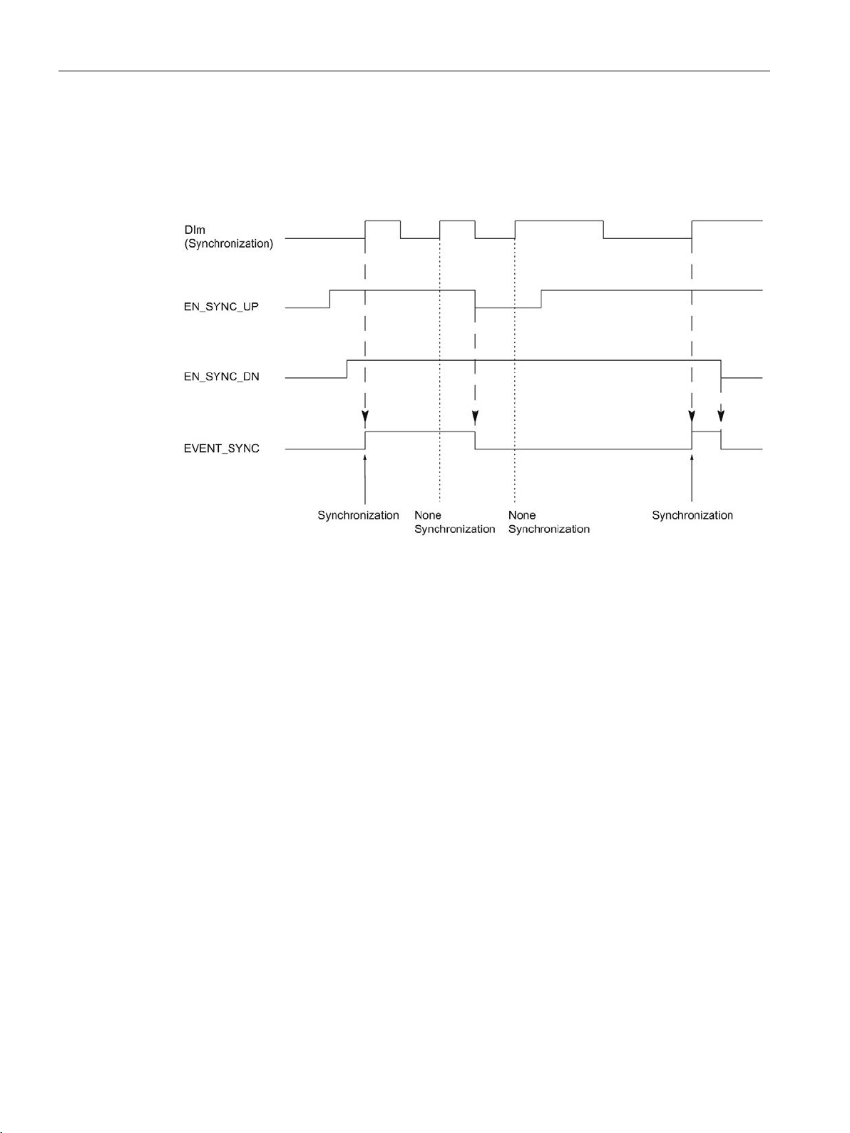
The figure below shows an example of the EN_SYNC_UP, EN_SYNC_DNand
EVENT_SYNC bits with single synchronization by an edge at a digital input for count pulses
in an upwards direction:
After synchronization is enabled for counting in an upwards direction, the counter is
synchronized at the first rising edge at the configured digital input. The counter can only be
synchronized again once the control bit (Page 185) EN_SYNC_UP has been reset and set
again.
Counting, measurement and position detection
36 Function Manual, 12/2017, A5E32009889-AG
Page 38
The basics of counting, measurement and position detection
Periodic synchronization
Hardware interrupt
2.2 Basics of counting, measuring and position input (TM Count, TM PosInput, Compact CPU)
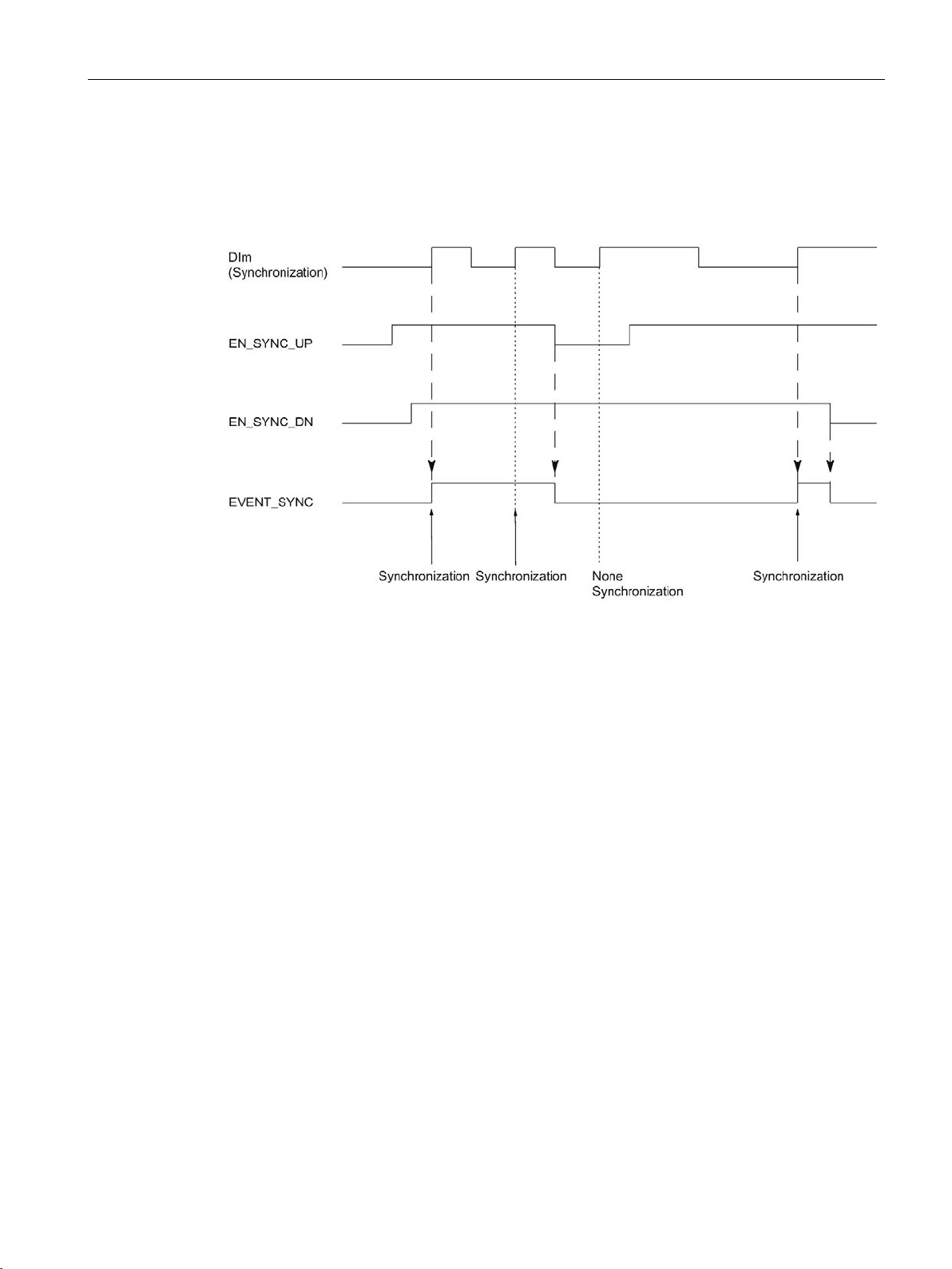
The figure below shows an example of the EN_SYNC_UP, EN_SYNC_DN and
EVENT_SYNC bits with periodic synchronization by an edge at a digital input for count
pulses in an upwards direction:
As long as synchronization for counting in an upwards direction is enabled, the counter is
synchronized at each rising edge at the configured digital input.
You can configure a hardware interrupt for the synchronization. The hardware interrupts will
be lost if the interrupt rate is higher than the system acknowledgement rate. You can signal a
lost hardware interrupt with a diagnostic interrupt.
Counting, measurement and position detection
Function Manual, 12/2017, A5E32009889-AG
37
Page 39
The basics of counting, measurement and position detection
2.2.7.1
Synchronization by digital input
Single synchronization
2.2 Basics of counting, measuring and position input (TM Count, TM PosInput, Compact CPU)
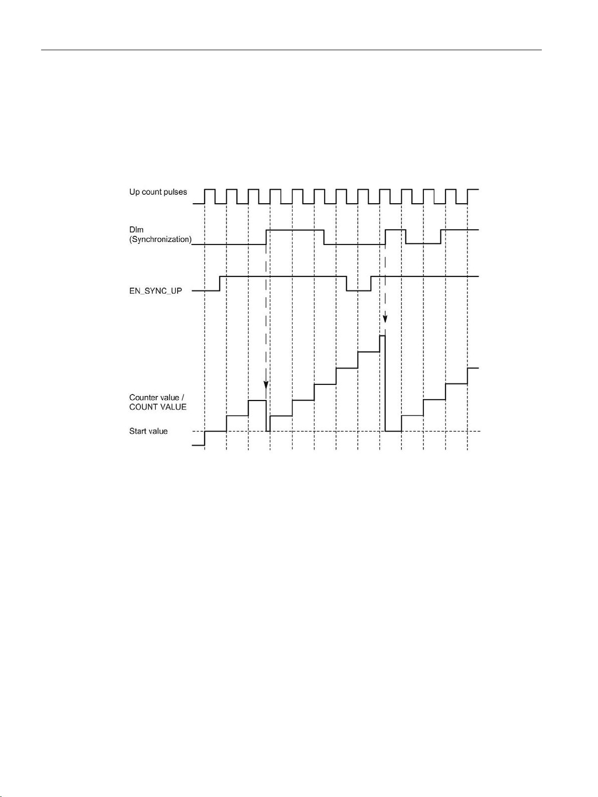
You can trigger synchronization by edges at a digital input.
The figure below shows an example for single synchronization by an edge at a digital input:
After synchronization is enabled for counting in an upwards direction, the counter is
synchronized at the first rising edge at the configured digital input. Until the control bit
(Page 185) EN_SYNC_UP has been reset and set again, any additional rising edge at the
digital output is ignored. The counter can then be synchronized again.
Counting, measurement and position detection
38 Function Manual, 12/2017, A5E32009889-AG
Page 40
The basics of counting, measurement and position detection
Periodic synchronization
2.2 Basics of counting, measuring and position input (TM Count, TM PosInput, Compact CPU)
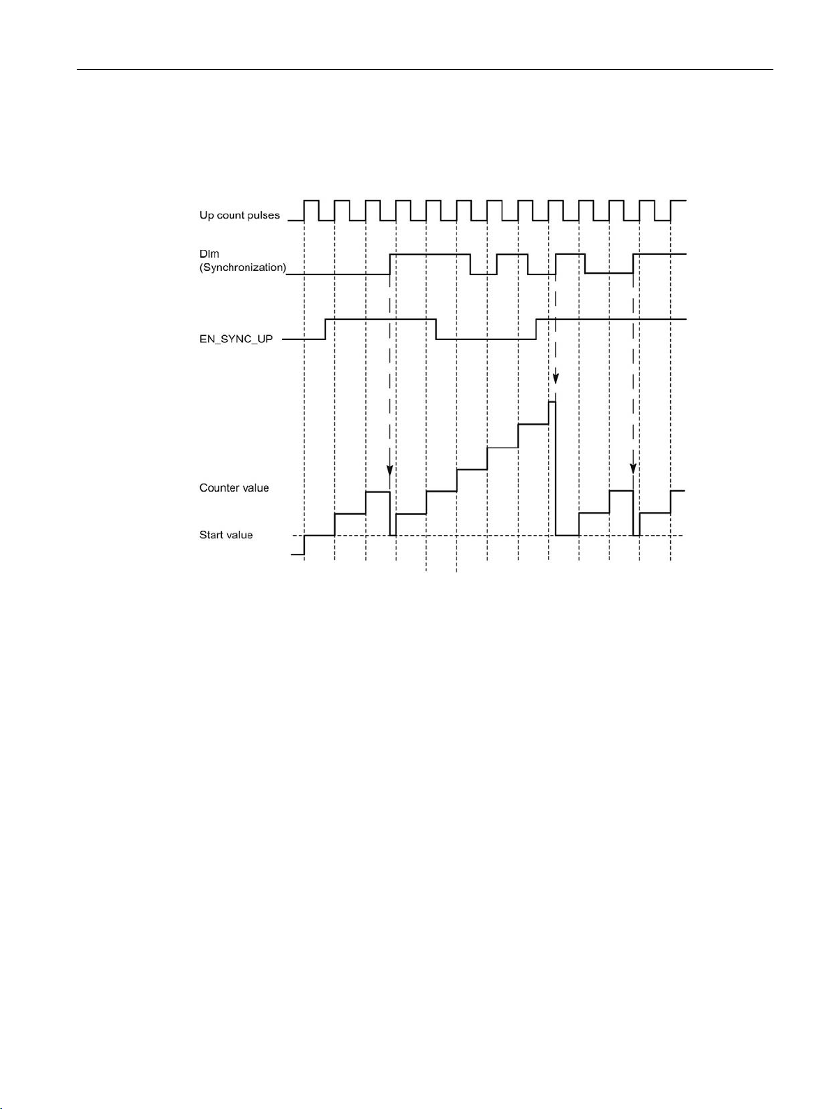
The figure below shows an example for periodic synchronization by an edge at a digital
input:
As long as synchronization for counting in an upwards direction is enabled, the counter is
synchronized at each rising edge at the configured digital input.
Counting, measurement and position detection
Function Manual, 12/2017, A5E32009889-AG
39
Page 41
The basics of counting, measurement and position detection
2.2.7.2
Synchronization at signal N
Single synchronization
2.2 Basics of counting, measuring and position input (TM Count, TM PosInput, Compact CPU)
You can trigger synchronization at signal N at the encoder input either directly or depending
on the status of a digital input.
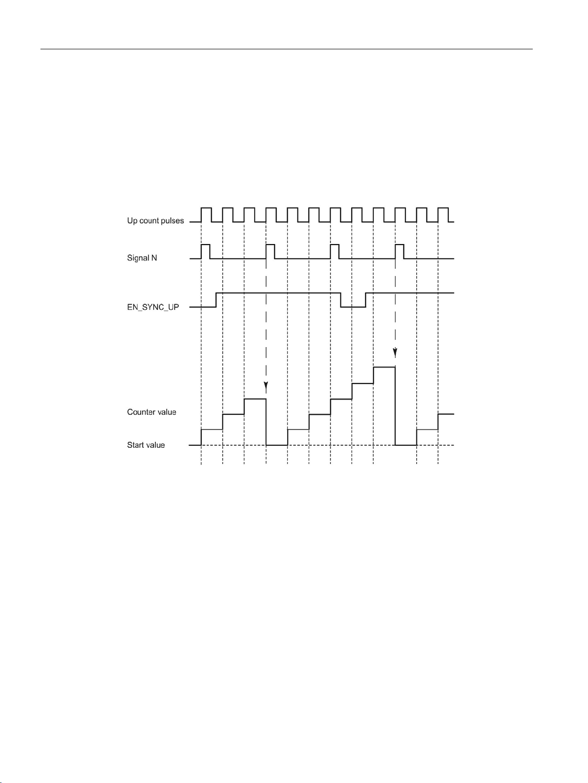
The figure below shows an example of single synchronization at signal N (not dependent on
a digital input):
After synchronization is enabled for counting in an upwards direction, the counter is
synchronized at the first signal N. After resetting and setting the control bit (Page 185)
EN_SYNC_UP once again, the counter can be synchronized again.
Counting, measurement and position detection
40 Function Manual, 12/2017, A5E32009889-AG
Page 42
The basics of counting, measurement and position detection
Periodic synchronization
2.2 Basics of counting, measuring and position input (TM Count, TM PosInput, Compact CPU)
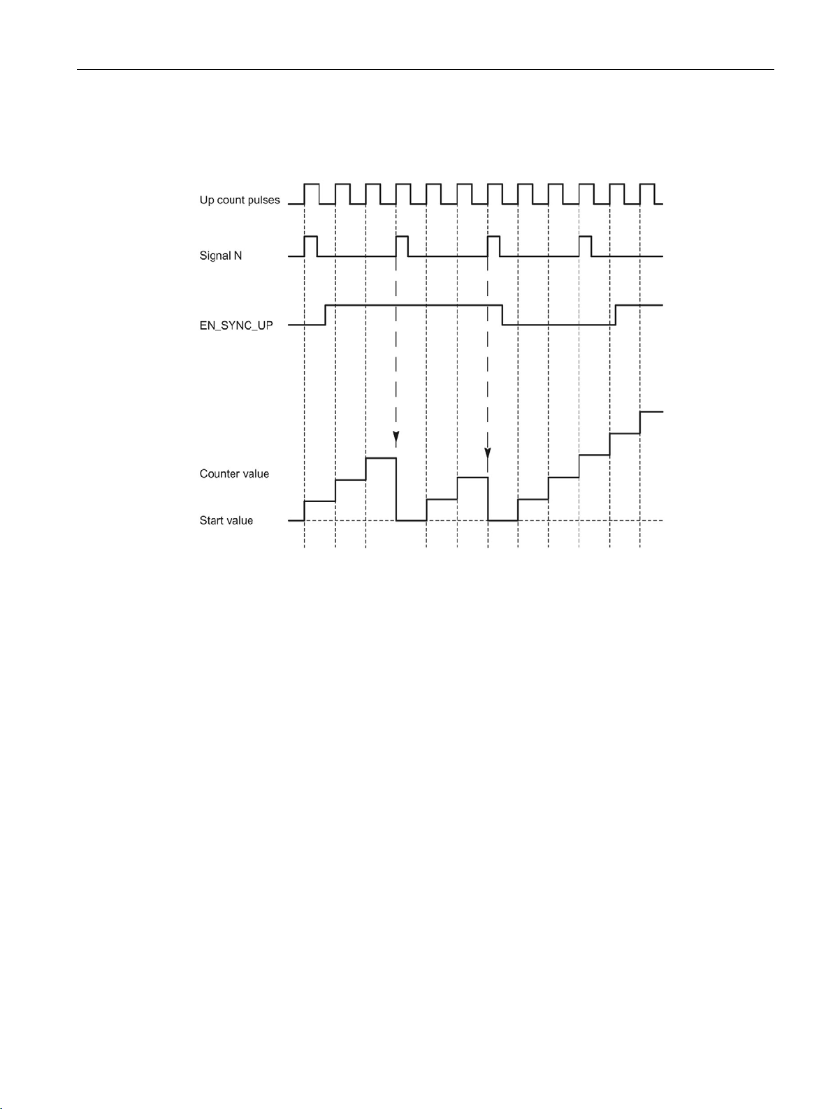
The figure below shows an example for periodic synchronization at signal N:
As long as synchronization for counting in an upwards direction is enabled, the counter is
synchronized at each signal N.
Counting, measurement and position detection
Function Manual, 12/2017, A5E32009889-AG
41
Page 43
The basics of counting, measurement and position detection
Enable by a digital input
2.2 Basics of counting, measuring and position input (TM Count, TM PosInput, Compact CPU)
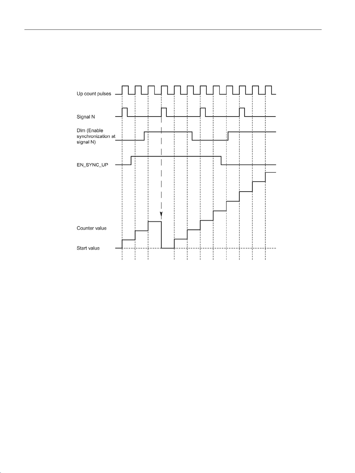
The figure below shows an example for periodic synchronization at signal N depending on
the status of a digital input:
As long as synchronization for counting up is enabled and the corresponding digital input is
active, the counter is synchronized at each signal N. If one of the conditions is not met, the
counter is not synchronized at the signal N.
Counting, measurement and position detection
42 Function Manual, 12/2017, A5E32009889-AG
Page 44

The basics of counting, measurement and position detection
2.2.8
Comparison values
2.2.8.1
Comparison values and outputs
Description
Note
DQ0 of a counter of a Compact CPU
With a Compact CPU, the respective digital output DQ0 is available via the feedback
interface, but not as a physical output.
Switching digital outputs from the user program
2.2 Basics of counting, measuring and position input (TM Count, TM PosInput, Compact CPU)
You can specify two comparison values to control both digital outputs of the channel
independently of the user program:
● Comparison value 0 for digital output DQ0
● Comparison value 1 for digital output DQ1
Depending on the operating mode and the encoder used, define two position, counter or
measured values as comparison value. Comparison value 1 must be greater than
comparison value 0. The comparison values are configurable and can be modified during
runtime using the user program.
The control bits (Page 185) TM_CTRL_DQ0 and TM_CTRL_DQ1 are used to control use of
the digital outputs.
If TM_CTRL_DQm is set to 0, you can control the relevant digital output from the user
program with the control bit SET_DQm regardless of the configured technological function. If
TM_CTRL_DQm is set to 1, the technological function of the controller of the respective
digital output is enabled.
The status of a digital output is indicated by the respective STS_DQm feedback bit.
Counting, measurement and position detection
Function Manual, 12/2017, A5E32009889-AG
43
Page 45
The basics of counting, measurement and position detection
2.2.8.2
Switching at comparison values with counter value as reference
Setting between comparison value and high counting limit
Setting between comparison value and low limit
2.2 Basics of counting, measuring and position input (TM Count, TM PosInput, Compact CPU)
The comparison values are compared with the current counter value. If the counter value
meets the assigned comparison condition and the technological function of the associated
digital output is enabled, the digital output is set. If you assign "Between comparison value 0
and 1" for digital output DQ1, both comparison values affect DQ1.
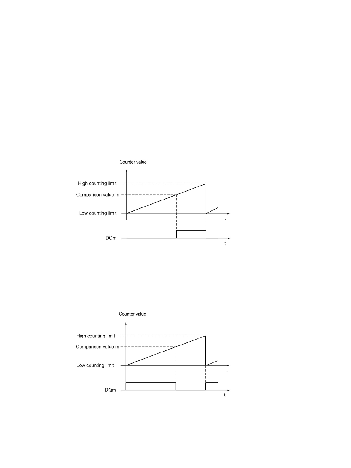
You can make switching for a digital output dependent on one of the following comparison
events:
The digital output is set to 1 if:
Comparison value <= counter value <= high counting limit
The comparison event is independent of the count direction.
The digital output is set to 1 if:
Low counting limit <= counter value <= comparison value
The comparison event is independent of the count direction.
Counting, measurement and position detection
44 Function Manual, 12/2017, A5E32009889-AG
Page 46
The basics of counting, measurement and position detection
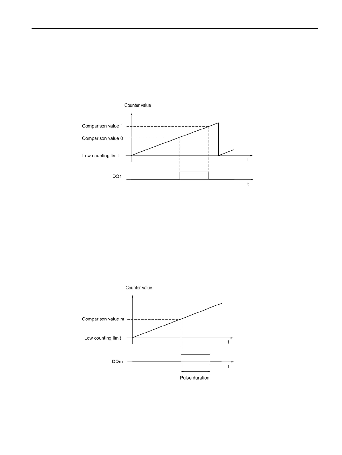
Setting between comparison value 0 and comparison value 1
Setting at comparison value for one pulse duration
2.2 Basics of counting, measuring and position input (TM Count, TM PosInput, Compact CPU)
The comparison event can be configured for the digital output DQ1 if "Use by user program"
has been configured for the digital output DQ0.
DQ1 is set to 1 if:
Comparison value 0 <= counter value <= comparison value 1
The comparison event is independent of the count direction.
The respective digital output is set to 1 for a specified period of time when the following
conditions are fulfilled:
● Counter value = comparison value
● Current count direction = configured count direction for the comparison event
The figure below shows an example of the comparison event when counting in an upwards
direction:
Counting, measurement and position detection
Function Manual, 12/2017, A5E32009889-AG
45
Page 47
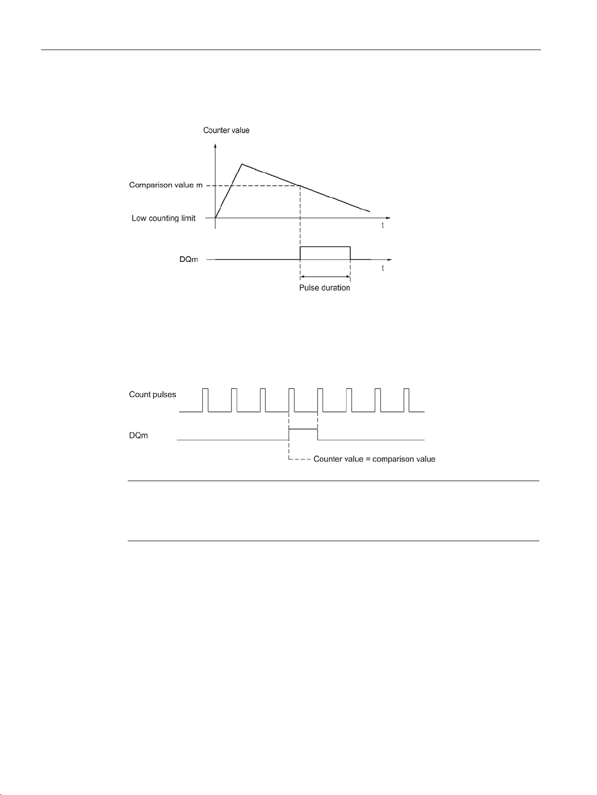
The basics of counting, measurement and position detection
Note
This comparison event switches the relevant digital output if a count pulse reaches the
comparison value. The digital output does not switch when the counter
synchronization for example.
2.2 Basics of counting, measuring and position input (TM Count, TM PosInput, Compact CPU)
The figure below shows an example of the comparison event when counting in a downward
direction:
To repeat the comparison event, the counter value must change and then correspond to the
respective comparison value again.
If the pulse duration has been defined as "0" and the counter value is equal to the
comparison value, the digital output is set to 1 until the next count pulse:
value is set, by
Counting, measurement and position detection
46 Function Manual, 12/2017, A5E32009889-AG
Page 48
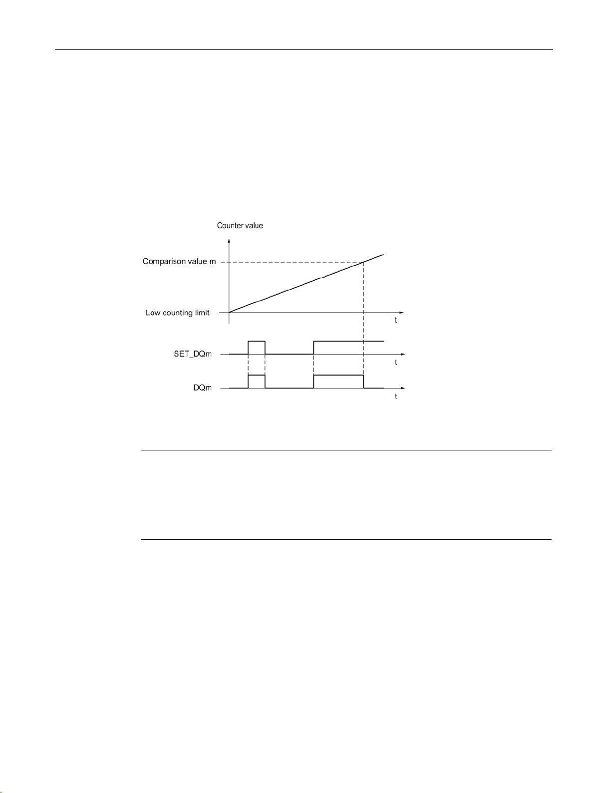
The basics of counting, measurement and position detection
Setting by the user program up to comparison value
Note
If the comparison value is reached in the configured count direction, the feedback bit
EVENT_CMPm is set independently of the state of the control bit SE
The comparison event switches a digital output when a count pulse reaches the respective
comparison value. The digital output does not switch when the counter value is set, by
synchronization for example.
2.2 Basics of counting, measuring and position input (TM Count, TM PosInput, Compact CPU)
You can set the respective digital output to 1 (edge) by setting the control bit (Page 185)
SET_DQm. The respective digital output is set to 0 by any of the following events:
● Match of the counter value and the comparison value in the configured direction of the
comparison event
● Reset of the corresponding SET_DQm control bit.
The figure below shows an example of the comparison event when counting in an upwards
direction:
You can disable the digital output before the counter value reaches the comparison value by
setting the control bit SET_DQm to 0.
T_DQm.
Counting, measurement and position detection
Function Manual, 12/2017, A5E32009889-AG
47
Page 49
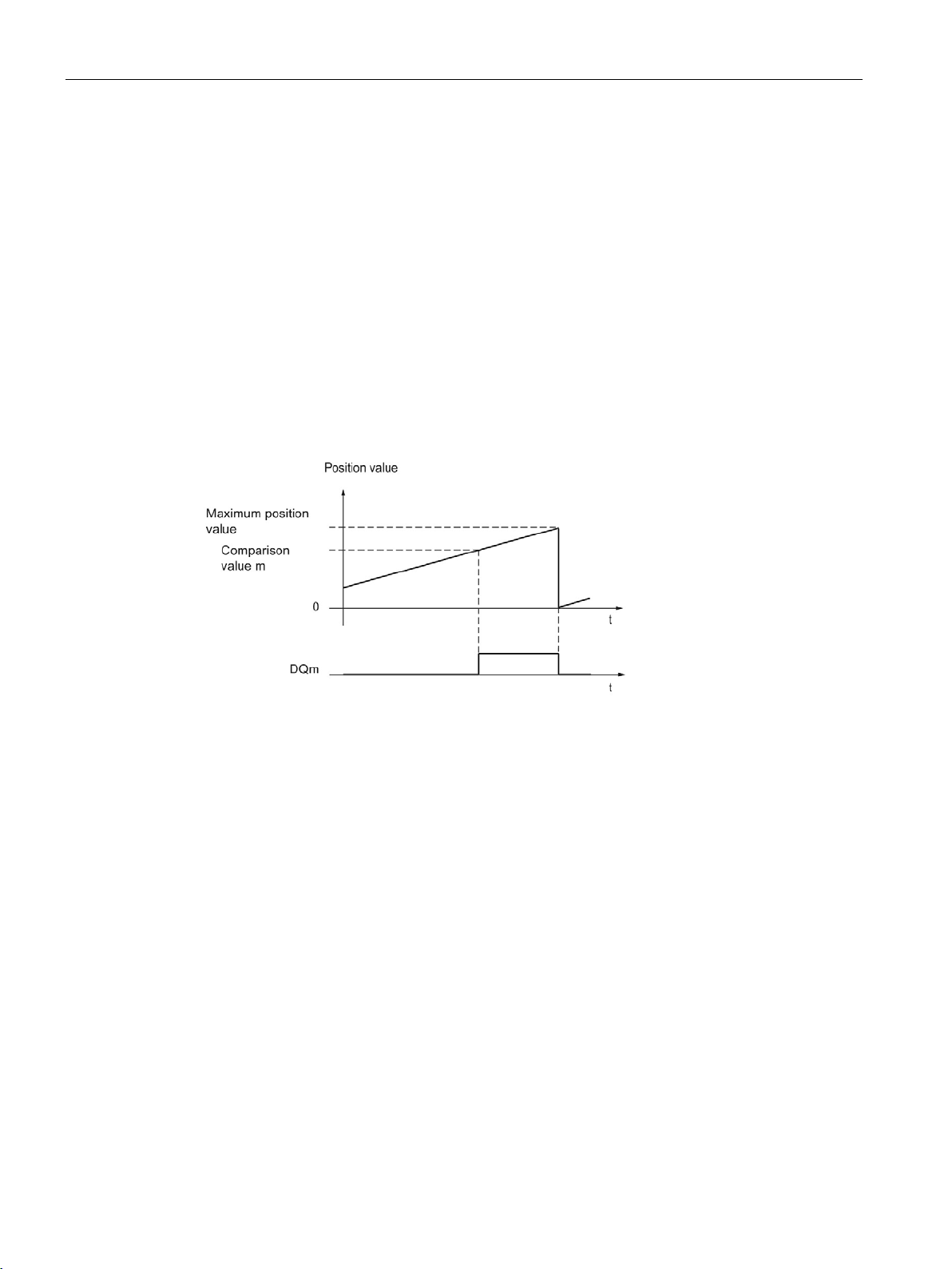
The basics of counting, measurement and position detection
2.2.8.3
Switching at comparison values with position value (SSI absolute value) as reference
Setting between comparison value and high limit
2.2 Basics of counting, measuring and position input (TM Count, TM PosInput, Compact CPU)
The comparison values are compared with the current position value. If the position value
meets the assigned comparison condition and the technological function of the associated
digital output is enabled, the digital output is set. If you assign "Between comparison value 0
and 1" for digital output DQ1, both comparison values affect DQ1.
You can make switching for a digital output dependent on one of the following comparison
events:
The high limit corresponds to the maximum position value.
The digital output is set to 1 if:
Comparison value <= position value <= maximum position value
The comparison event is independent of the direction of the position value change. The
maximum position value depends on the resolution of the SSI absolute encoder.
Counting, measurement and position detection
48 Function Manual, 12/2017, A5E32009889-AG
Page 50
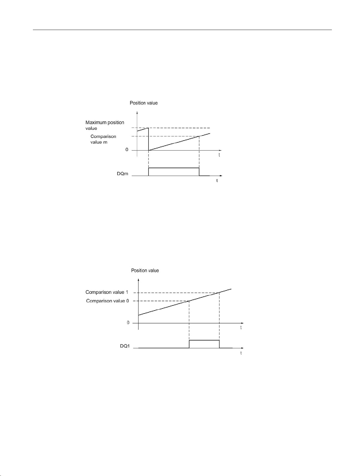
The basics of counting, measurement and position detection
Setting between comparison value and low limit
Setting between comparison value 0 and comparison value 1
2.2 Basics of counting, measuring and position input (TM Count, TM PosInput, Compact CPU)
The low limit corresponds to the position value "0".
The digital output is set to 1 if:
0 <= position value <= comparison value
The comparison event is independent of the direction of the position value change.
The comparison event can be configured for the digital output DQ1 if "Use by user program"
has been configured for the digital output DQ0.
DQ1 is set to 1 if:
Comparison value 0 <= position value <= comparison value 1
The comparison event is independent of the direction of the position value change.
Counting, measurement and position detection
Function Manual, 12/2017, A5E32009889-AG
49
Page 51
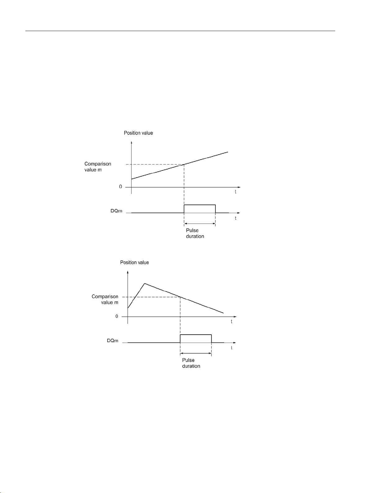
The basics of counting, measurement and position detection
Setting at comparison value for one pulse duration
2.2 Basics of counting, measuring and position input (TM Count, TM PosInput, Compact CPU)
The respective digital output is set to 1 for a specified period of time when the following
conditions are fulfilled:
● Matching of the position value and comparison value or crossing of the comparison value
● Current direction of the position value change = assigned direction for the comparison
event
The figure below shows an example of the comparison event when counting up:
The figure below shows an example of the comparison event when counting down:
To repeat the comparison event, the position value must change and then correspond to or
cross the respective comparison value again.
Counting, measurement and position detection
50 Function Manual, 12/2017, A5E32009889-AG
Page 52
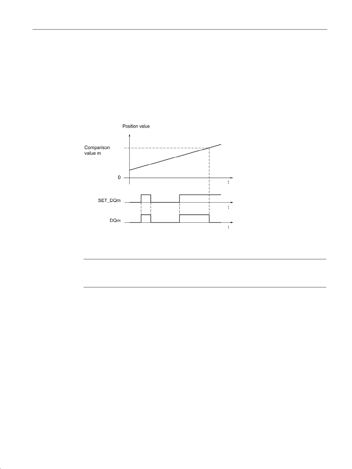
The basics of counting, measurement and position detection
Setting by the user program up to comparison value
Note
If the comparison value is reached or exceeded in the assigned direction, feedback bit
EVENT_CMPm is set
2.2 Basics of counting, measuring and position input (TM Count, TM PosInput, Compact CPU)
You can set each digital output to 1 (edge) by setting the control bit (Page 185) SET_DQm.
The respective digital output is set to 0 by any of the following events:
● Matching of the position value and the comparison value or crossing of the comparison
value in the configured direction of the comparison event
● Resetting of the SET_DQm control bit.
The figure below shows an example of the comparison event when counting up:
You can disable the digital output before the position value corresponds to or exceeds the
comparison value by setting the control bit SET_DQm to 0.
independently of the status of control bit SET_DQm.
Counting, measurement and position detection
Function Manual, 12/2017, A5E32009889-AG
51
Page 53
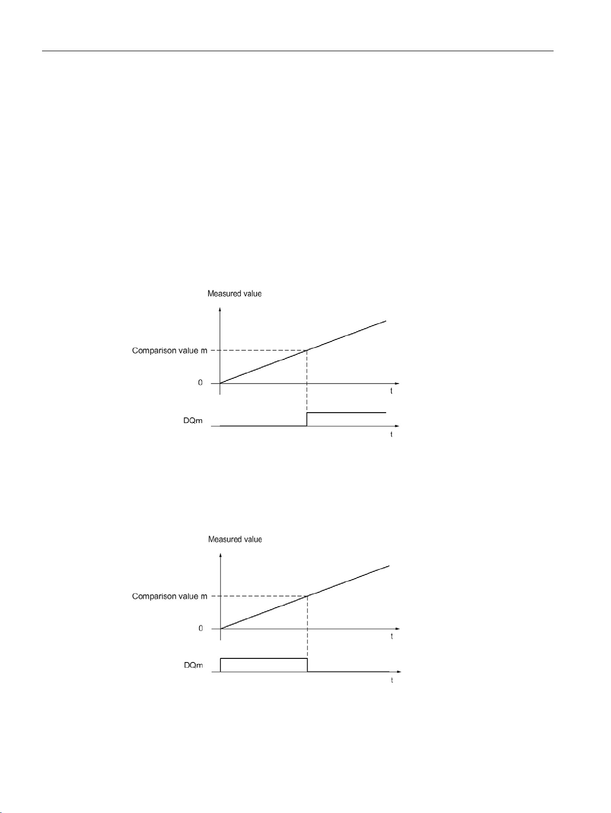
The basics of counting, measurement and position detection
2.2.8.4
Switching at comparison values with measured value as reference
Setting above the comparison value
Setting below the comparison value
2.2 Basics of counting, measuring and position input (TM Count, TM PosInput, Compact CPU)
The comparison values are compared with the current measured value. If the measured
value meets the configured comparison condition and the technological function of the
corresponding digital output is enabled, the digital output is set. If you configure "Between
comparison value 0 and 1" or "Not between comparison value 0 and 1" for digital output
DQ1, both comparison values affect DQ1.
You can make switching for a digital output dependent on one of the following comparison
events:
The digital output is set to 1 if:
Measured value >= comparison value
The digital output is set to 1 if:
Measured value <= comparison value
Counting, measurement and position detection
52 Function Manual, 12/2017, A5E32009889-AG
Page 54
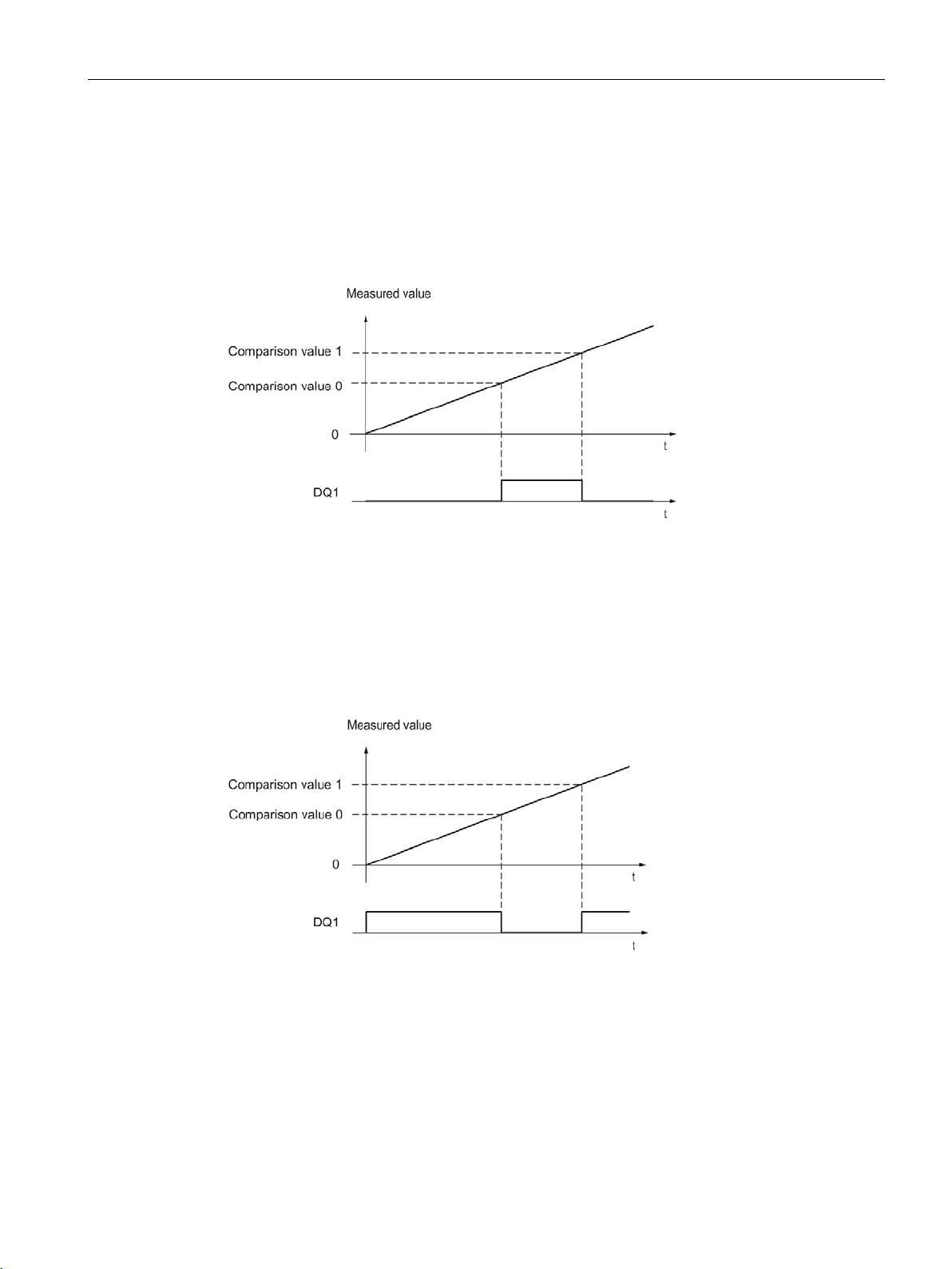
The basics of counting, measurement and position detection
Setting between comparison value 0 and comparison value 1
Not setting between comparison value 0 and comparison value 1
2.2 Basics of counting, measuring and position input (TM Count, TM PosInput, Compact CPU)
The comparison event can be configured for the digital output DQ1 if "Use by user program"
has been configured for the digital output DQ0.
DQ1 is set to 1 if:
Comparison value 0 <= measured value <= comparison value 1
The comparison event can be configured for the digital output DQ1 if "Use by user program"
has been configured for the digital output DQ0.
DQ1 is set to 1 if:
Comparison value 1 <= measured value <= comparison value 0
Counting, measurement and position detection
Function Manual, 12/2017, A5E32009889-AG
53
Page 55
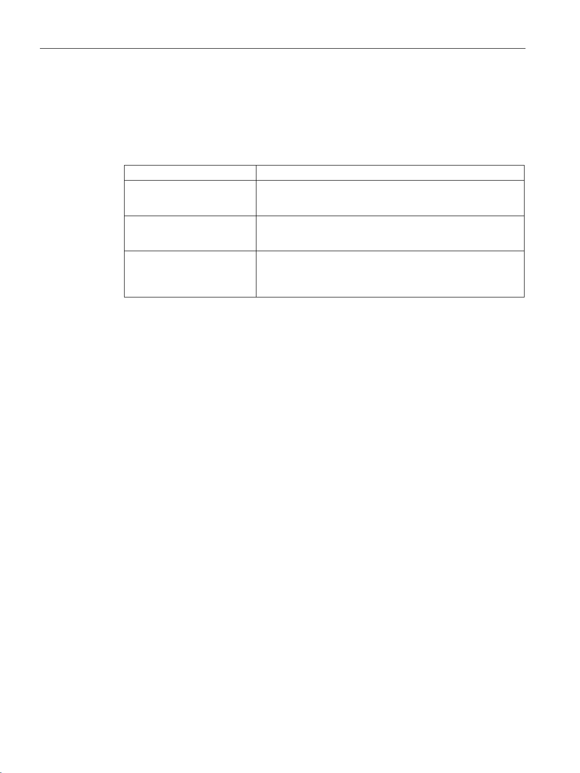
The basics of counting, measurement and position detection
2.2.9
Measured value determination
2.2.9.1
Overview of measuring functions
Measurement type (Page 55)
Description
changes and returned in Hertz as floating point number.
changes and returned in seconds as floating point number.
of measurement.
Update time
Gate control for incremental and pulse encoders
2.2 Basics of counting, measuring and position input (TM Count, TM PosInput, Compact CPU)
The following measuring functions are available:
Frequency measurement The mean frequency is calculated at set measuring intervals on the
basis of the time profile of the count pulses or position value
Period measurement The mean period duration is calculated at set measuring intervals
on the basis of the time profile of the count pulses or position value
Velocity measurement The mean velocity is calculated at set measuring intervals on the
basis of the time profile of the count pulses or position value
changes and other parameters, and returned in the configured unit
Measured values and counter values are available concurrently in the feedback interface.
You can configure the interval at which the technology module updates the measured values
cyclically as the update time. Setting longer update time intervals allows uneven measured
variables to be smoothed and increases measuring accuracy.
Opening and closing the internal gate defines the period of time during which the count
pulses are captured. The update time is asynchronous to the opening of the gate, which
means that the update time is not started when the gate is opened. After the internal gate is
closed, the last measured value captured is still returned.
Counting, measurement and position detection
54 Function Manual, 12/2017, A5E32009889-AG
Page 56
The basics of counting, measurement and position detection
2.2.9.2
Measured value determination with incremental or pulse encoder
Measuring range (TM Count and TM PosInput)
Measurement type
Low measuring range limit
High measuring range limit
Frequency measurement
0.04 Hz
800 kHz* / 4 MHz**
Period measurement
1.25 µs* / 0.25 µs**
25 s
"time base for velocity measurement"
* Applies to 24
** Applies to RS422 incremental encoders and "quadruple" signal evaluation.
Measuring range (Compact CPU)
Measurement type
Low measuring range limit
High measuring range limit
Frequency measurement
0.04 Hz
400 kHz*
Period measurement
2.5 µs*
25 s
"Time base for velocity measurement"
* Applies to 24 V incremental encoders and "quadruple“ signal evaluation.
Measuring principle
2.2 Basics of counting, measuring and position input (TM Count, TM PosInput, Compact CPU)
The measuring functions have the following measuring limits:
Velocity measurement Depending on the configured number of "increments per unit" and the
V incremental encoders and "quadruple" signal evaluation.
All measured values are returned as signed values. The sign indicates whether the counter
value increased or decreased during the relevant time period.
The measuring functions have the following measuring range limits:
Velocity measurement Depends on the configured number of "Increments per unit" and the
All measured values are returned as signed values. The sign indicates whether the counter
value increased or decreased during the relevant time period.
The technology module assigns a time value to each count pulse. The measuring interval is
defined as the time between each last count pulse before and during the previous update
time. The measuring interval and the number of pulses in the measuring interval are
evaluated to calculate measured variables.
If there is no count pulse within an update time, the measuring interval is dynamically
adjusted. In this case, a pulse is assumed at the end of the update time and the measuring
interval is calculated as the time between that point and the last pulse which occurred. The
number of pulses is then 1.
The feedback bit STS_M_INTERVAL indicates whether a count pulse occurred in the
previous measuring interval. This allows for a differentiation between an assumed and an
actual count pulse.
Counting, measurement and position detection
Function Manual, 12/2017, A5E32009889-AG
55
Page 57
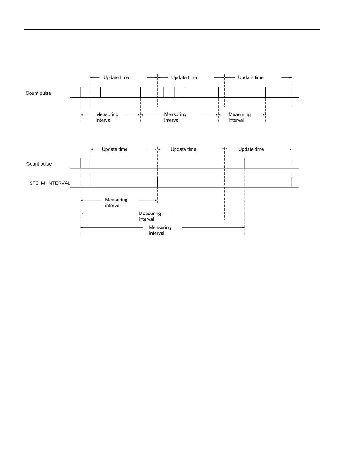
The basics of counting, measurement and position detection
2.2 Basics of counting, measuring and position input (TM Count, TM PosInput, Compact CPU)
The following figures show the principle of measurement and the dynamic adjustment of the
measuring interval:
Counting, measurement and position detection
56 Function Manual, 12/2017, A5E32009889-AG
Page 58
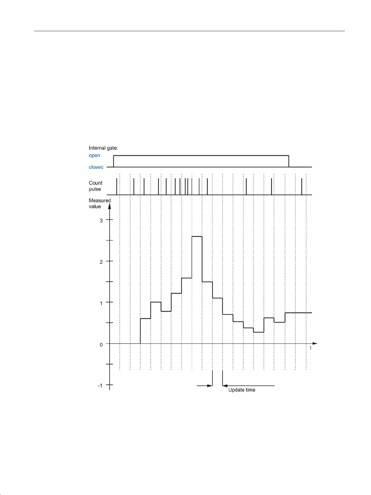
The basics of counting, measurement and position detection
Frequency measurement
2.2 Basics of counting, measuring and position input (TM Count, TM PosInput, Compact CPU)
A value "0" is returned until the first measured value is available.
The measurement process begins with the first pulse detected once the internal gate has
been opened. The first measured value can be calculated after the second pulse at the
earliest.
The measured value is updated in the feedback interface (Page 188) upon completion of
each update time. If the internal gate is closed, measuring stops and the measured value is
no longer updated.
The figures below shows an example of frequency measurement with an update time of 1 s:
Counting, measurement and position detection
Function Manual, 12/2017, A5E32009889-AG
57
Page 59

The basics of counting, measurement and position detection
Period measurement
Velocity measurement
Example:
2.2 Basics of counting, measuring and position input (TM Count, TM PosInput, Compact CPU)
The reciprocal of the frequency is output as the measured value for period measurement.
A value "25 s" is returned until the first measured value is available.
The normalized frequency is output as the measured value in velocity measurement. You
can configure the scaling using the time basis and the number of increments that your
encoder delivers per unit.
Your encoder delivers 4000 increments per meter. The velocity is to be measured in meters
per minute.
In this case, you need to configure 4000 Increments per unit and a time basis of one minute.
Counting, measurement and position detection
58 Function Manual, 12/2017, A5E32009889-AG
Page 60
The basics of counting, measurement and position detection
2.2.9.3
Measured value determination with SSI absolute encoder
Measuring range SSI absolute encoder
Measurement type
Low measuring range limit
High measuring range limit
Frequency measurement
0,04 Hz
4 MHz
Period measurement
0,25 μs
25 s
"time base for velocity measurement"
Measuring principle
2.2 Basics of counting, measuring and position input (TM Count, TM PosInput, Compact CPU)
The measuring functions have the following measuring limits:
Velocity measurement Depending on the configured number of "increments per unit" and the
All measured values are returned as signed values. The sign indicates whether the position
value increased or decreased during the relevant time period.
The technology module assigns a time value to each SSI frame. The measuring interval is
defined as the time between the last SSI frame with a change of position value before and
during the previous update time. The measuring interval and the total change in position
value in the measuring interval are evaluated to calculate a measured variable. The total
change in position value in a measuring interval corresponds to the number of encoder
increments in the same measuring interval.
If there is no change in position value within an update time, the measuring interval is
dynamically adjusted. In this case, a change in position value is assumed at the end of the
update time and the measuring interval is calculated as the time between that point and the
last SSI frame with a change in position value. The change in position value is then 1.
The feedback bit STS_M_INTERVAL indicates whether a change in position value occurred
in the previous measuring interval. This allows for a differentiation between an assumed and
an actual change in position value. If the technology module cannot calculate measured
values because the measuring range limit has been violated, the feedback bit
STS_M_INTERVAL is not set.
Counting, measurement and position detection
Function Manual, 12/2017, A5E32009889-AG
59
Page 61
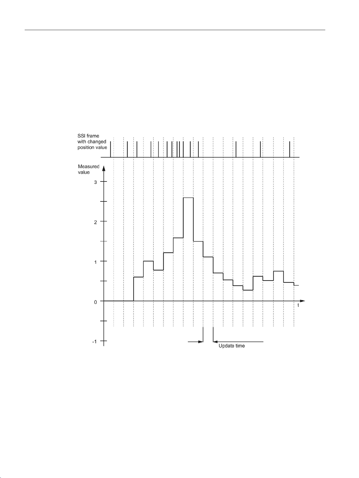
The basics of counting, measurement and position detection
Frequency measurement
Period measurement
2.2 Basics of counting, measuring and position input (TM Count, TM PosInput, Compact CPU)
The value "0.0" is reported in the time up to the first available measured value.
The measuring process begins with the first detected change in position value. The first
measured value can be calculated after the second detected change in position value at the
earliest.
The measured value is updated in the feedback interface (Page 188) upon completion of
each update time.
The figures below shows an example of frequency measurement with an update time of 1 s:
The reciprocal of the frequency is output as the measured value for period measurement.
A value "25 s" is returned until the first measured value is available.
Counting, measurement and position detection
60 Function Manual, 12/2017, A5E32009889-AG
Page 62

The basics of counting, measurement and position detection
Velocity measurement
Example:
2.2 Basics of counting, measuring and position input (TM Count, TM PosInput, Compact CPU)
The normalized frequency is output as the measured value in velocity measurement. You
can configure the scaling using the time basis and the number of increments that your
encoder delivers per unit.
Your SSI absolute encoder operates with a resolution of 12 bits per revolution and performs
4096 increments per revolution. The velocity should be measured in revolutions per minute.
In this case, you need to configure 4096 Increments per unit and a time basis of one minute.
Counting, measurement and position detection
Function Manual, 12/2017, A5E32009889-AG
61
Page 63
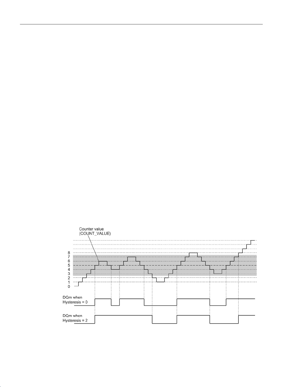
The basics of counting, measurement and position detection
2.2.10
Hysteresis
2.2.10.1
Hysteresis with incremental or pulse encoder
Description
Function principle
2.2 Basics of counting, measuring and position input (TM Count, TM PosInput, Compact CPU)
Hysteresis allows you to specify a range around the comparison values within which the
digital outputs are not to be switched again until the counter value has gone outside this
range.
Slight movements by the encoder can result in the counter value fluctuating around a certain
value. If a comparison value or a counting limit lies within this fluctuation range, the
corresponding digital output is switched on and off with corresponding frequency if hysteresis
is not used. Hysteresis prevents this unwanted switching, and configured hardware interrupts
when a comparison event occurs.
The hysteresis becomes active when the respective comparison value is reached by a count
pulse. If the counter value is set to the start value during an active hysteresis, the hysteresis
becomes inactive.
Regardless of the hysteresis value, the hysteresis range ends at the low/high counting limits.
The figure below shows an example for the hysteresis with the following configuration:
● Setting of a digital output between comparison value and high counting limit
● Comparison value = 5
● Hysteresis = 0 or 2 (gray background)
Hysteresis is enabled when the counter value 5 is reached. When the hysteresis is active,
the comparison result remains unchanged. Hysteresis is disabled when the counter value 2
or 8 is reached.
Counting, measurement and position detection
62 Function Manual, 12/2017, A5E32009889-AG
Page 64
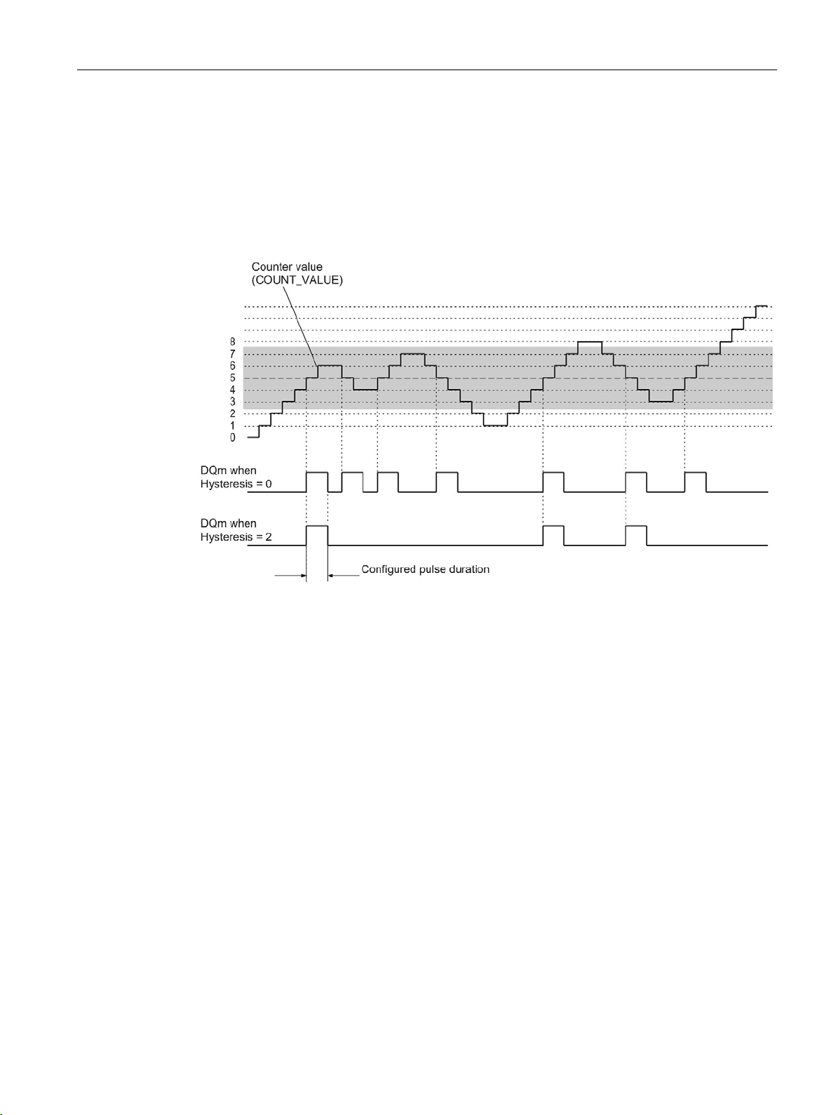
The basics of counting, measurement and position detection
2.2 Basics of counting, measuring and position input (TM Count, TM PosInput, Compact CPU)
The figure below shows an example for the hysteresis with the following configuration:
● Setting at comparison value for one pulse duration
● Comparison value = 5
● Comparison in both count directions
● Hysteresis = 0 or 2 (gray background)
Counting, measurement and position detection
Function Manual, 12/2017, A5E32009889-AG
63
Page 65
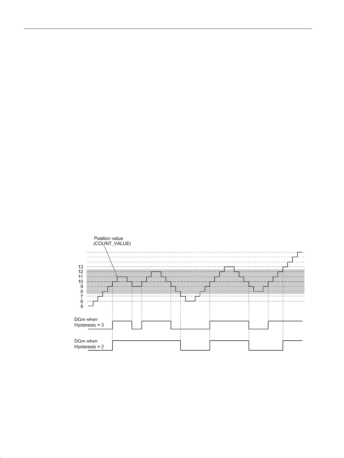
The basics of counting, measurement and position detection
2.2.10.2
Hysteresis with SSI absolute encoder
Description
Function principle
2.2 Basics of counting, measuring and position input (TM Count, TM PosInput, Compact CPU)
Hysteresis allows you to specify a range around the comparison values within which the
digital outputs are not to be switched again until the position value has gone outside this
range.
Slight movements by the encoder can result in the position value fluctuating around a certain
value. If a comparison value, "0", or the respective maximum position value lies within this
fluctuation range, the associated digital output is switched on and off with corresponding
frequency if a hysteresis is not used. Hysteresis prevents this unwanted switching, and
configured hardware interrupts when a compare event occurs.
Regardless of the hysteresis value, the hysteresis range ends at "0" and at the respective
maximum position value.
The figure below shows an example for the hysteresis with the following parameter
assignment:
● Setting of a digital output between comparison value and high limit
● Comparison value = 10
● Hysteresis = 0 or 2 (gray background)
Hysteresis is enabled when the position value 10 is reached. When the hysteresis is active,
the comparison result remains unchanged. Hysteresis is disabled when the position values 7
or 13 are reached.
Counting, measurement and position detection
64 Function Manual, 12/2017, A5E32009889-AG
Page 66
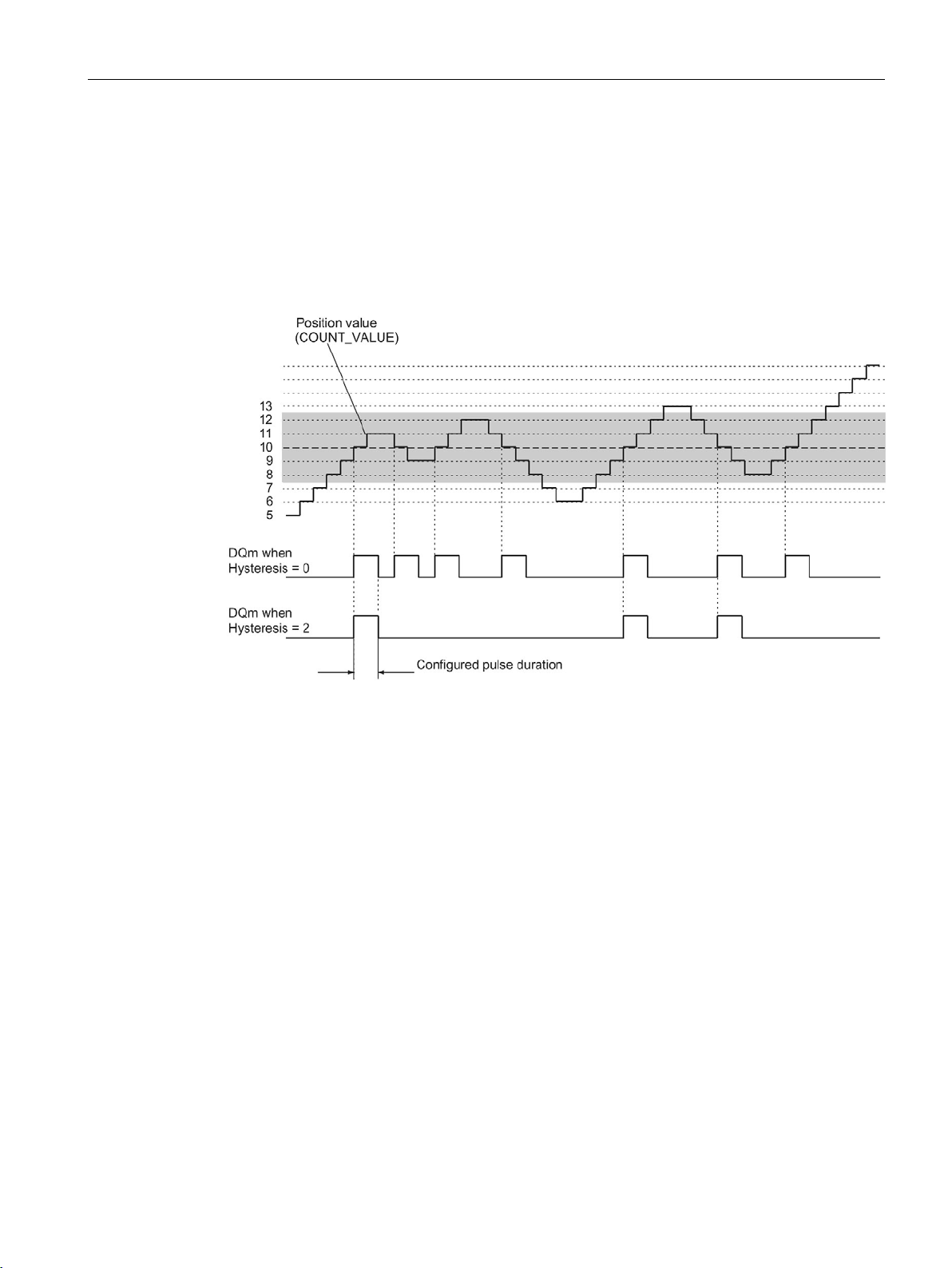
The basics of counting, measurement and position detection
2.2 Basics of counting, measuring and position input (TM Count, TM PosInput, Compact CPU)
The figure below shows an example for the hysteresis with the following parameter
assignment:
● Setting at comparison value for one pulse duration
● Comparison value = 10
● Comparison in both directions of position value changes
● Hysteresis = 0 or 2 (gray background)
Counting, measurement and position detection
Function Manual, 12/2017, A5E32009889-AG
65
Page 67

The basics of counting, measurement and position detection
2.2.11
Interrupts
Hardware interrupt
Diagnostic interrupt
2.2.12
Position detection for Motion Control
Description
2.2 Basics of counting, measuring and position input (TM Count, TM PosInput, Compact CPU)
The technology module can trigger a hardware interrupt in the CPU if, for example, a
comparison event occurs; in the event of overflow or underflow; in the event of a zero
crossing of the counter and/or of a change in count direction (direction reversal). You can
specify which events are to trigger a hardware interrupt during operation.
The technology module can trigger diagnostic interrupts in the event of errors. You enable
the diagnostic interrupts for certain errors in the device configuration. Refer to the device
manual for the technology module to learn about the events that can trigger a diagnostic
interrupt during operation.
You can use the technology module with S7-1500 Motion Control for position detection.
In the device configuration of the technology module in STEP 7 (TIA Portal), select "Position
input for technology object "Motion Control"". This reduces the configuration options to the
parameters that are essential. For TM Count or TM PosInput, the mode automatically applies
to all channels of the technology module. For a Compact CPU, the mode automatically
applies to the respective channel.
When using an incremental or pulse encoder, the position input is based on the counting
function of the technology module. With an SSI absolute encoder, the absolute value is read
in via a synchronous, serial interface and prepared according to the parameter assignment
and made available for S7-1500 Motion Control.
You can find information about the remaining configuring steps in the help for the axis
technology objects of S7-1500 Motion Control.
Counting, measurement and position detection
66 Function Manual, 12/2017, A5E32009889-AG
Page 68
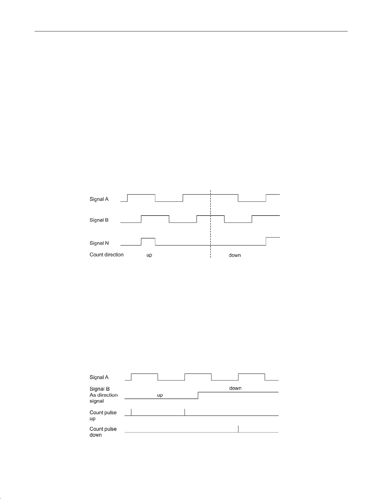
The basics of counting, measurement and position detection
2.2.13
Encoder signals
2.2.13.1
24 V and TTL count signals
24 V and TTL incremental encoder count signals
24 V and TTL pulse encoder count signals without/with direction signal
2.2 Basics of counting, measuring and position input (TM Count, TM PosInput, Compact CPU)
The 24 V incremental encoder returns the 24 V signals A, B, and N to the technology
module. The A and B signals are phase-shifted by 90°. You can also connect incremental
encoders without an N signal.
A 24 V incremental encoder uses the A and B signals for counting. If configured accordingly,
the N signal is used for setting the counter to the start value or for saving the current counter
value to the Capture value.
The figure below shows an example of the time profile of the signals of an 24 V incremental
encoder:
The technology module detects the count direction by evaluating the sequence of edges of
the A and B signals. You can specify an inversion of the count direction.
The encoder, for example an initiator (BERO) or a light barrier, returns only a count signal
that is connected to terminal A of the counter.
In addition, you can connect a signal for direction detection to terminal B of the counter. If
your encoder does not return a corresponding signal, you can specify the count direction
with the user program using the control interface.
The figure below shows an example of the time profile of the signals of a 24 V pulse encoder
with direction signal and the resulting count pulses:
Counting, measurement and position detection
Function Manual, 12/2017, A5E32009889-AG
67
Page 69
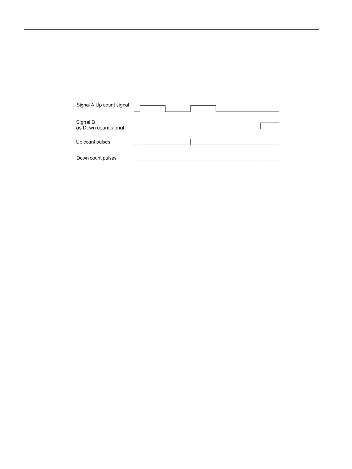
The basics of counting, measurement and position detection
24 V and TTL pulse encoder count signals with Up/Down count signal
Sourcing output/sinking output for 24 V counter signals (TM Count)
Sourcing output for 24 V counter signals (Compact CPU)
Monitoring of the encoder signals (TM Count and TM PosInput)
2.2 Basics of counting, measuring and position input (TM Count, TM PosInput, Compact CPU)
The Up count signal is connected to terminal A. The Down count signal is connected to
terminal B.
The figure below shows an example of the time profile of the signals of a pulse encoder with
Up/Down count signal and the resulting count pulses:
You can connect the following encoders/sensors to the counter inputs:
● Sourcing output:
The A, B, and N inputs are wired to 24VDC .
● Sinking output:
The A, B, and N inputs are wired to ground M .
● Push-pull (sourcing and sinking output):
The A, B, and N inputs are wired alternately to 24VDC and ground M .
You can connect the sourcing output and push-pull encoders or sensors to the counter
inputs.
The signals of push-pull 24 V sensors are monitored for wire breaks by the technology
module. TTL signal are monitored for offset voltage by the technology module.
If you enable the diagnostic interrupt in the device configuration, the technology module
triggers a diagnostic interrupt in the event of encoder signal errors.
Counting, measurement and position detection
68 Function Manual, 12/2017, A5E32009889-AG
Page 70
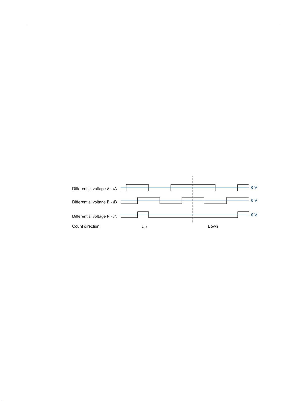
The basics of counting, measurement and position detection
2.2.13.2
RS422 count signals
RS422 incremental encoder count signals
2.2 Basics of counting, measuring and position input (TM Count, TM PosInput, Compact CPU)
The RS422 incremental encoder sends the following differential signals to the technology
module:
● A and /A
● B and /B
● N and /N
The signal information for RS422 signals is encoded in the differential voltage between A
and /A, B and /B or N and /N. The A and B signals are phase-shifted by 90°. You can also
connect incremental encoders without an N signal.
RS422 incremental encoders use the A and B signals for counting. If configured accordingly,
the N signal is used for setting the counter to the start value or for saving the current counter
value as the Capture value.
The figure below shows an example of the time profile of the signals of an RS422
incremental encoder:
The technology module detects the count direction by evaluating the sequence of edges of
the A and B signals. You can specify an inversion of the count direction.
Counting, measurement and position detection
Function Manual, 12/2017, A5E32009889-AG
69
Page 71
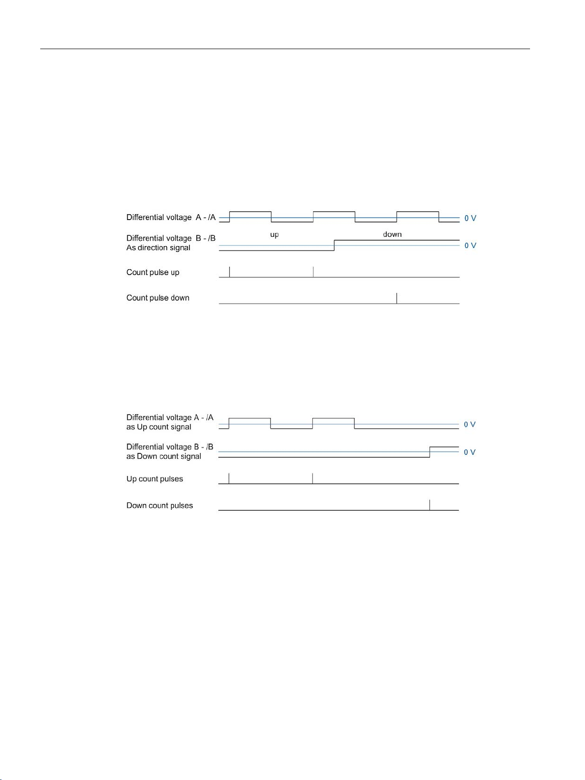
The basics of counting, measurement and position detection
Count signals of RS422 pulse encoders without/with direction signal
Count signals of RS422 pulse encoders with Up/Down count signal
Monitoring of encoder signals
2.2 Basics of counting, measuring and position input (TM Count, TM PosInput, Compact CPU)
The encoder, for example a light barrier, only returns a count signal that is connected to
terminal A.
You can also connect a signal for direction detection to terminal B. If your encoder does not
return a corresponding signal, you can specify the count direction with the user program
using the control interface.
The figure below shows an example of the time profile of the signals of a RS422 pulse
encoder with direction signal and the resulting count pulses:
The Up count signal is connected to the A terminals. The Down count signal is connected to
the B terminals.
The figure below shows an example of the time profile of the signals of an RS422 pulse
encoder with Up/Down count signal and the resulting count pulses:
The technology module monitors RS422 signals for wire breaks, short-circuits, and offset
voltages.
If you enable the diagnostic interrupt in the device configuration, the technology module
triggers a diagnostic interrupt in the event of encoder signal errors.
Counting, measurement and position detection
70 Function Manual, 12/2017, A5E32009889-AG
Page 72

The basics of counting, measurement and position detection
2.2.13.3
SSI signals
Signals from SSI absolute encoders
Monitoring of the encoder signals and the SSI frames
2.2 Basics of counting, measuring and position input (TM Count, TM PosInput, Compact CPU)
The SSI absolute encoder and the technology module communicate via SSI data signals
DAT and /DAT (D) and the SSI clock signals CLK and /CLK (C). SSI uses the RS422 signal
standard. The signal information is coded in the respective differential voltage between C
and /C as well as D and /D.
The technology module monitors the signals of an SSI absolute encoder for wire breaks,
short-circuits, and offset voltages. The technology module also monitors SSI frames for
errors.
If you enable the diagnostic interrupts in the device configuration, the technology module
triggers a diagnostic interrupt in the event of encoder signal or SSI frame errors.
Counting, measurement and position detection
Function Manual, 12/2017, A5E32009889-AG
71
Page 73
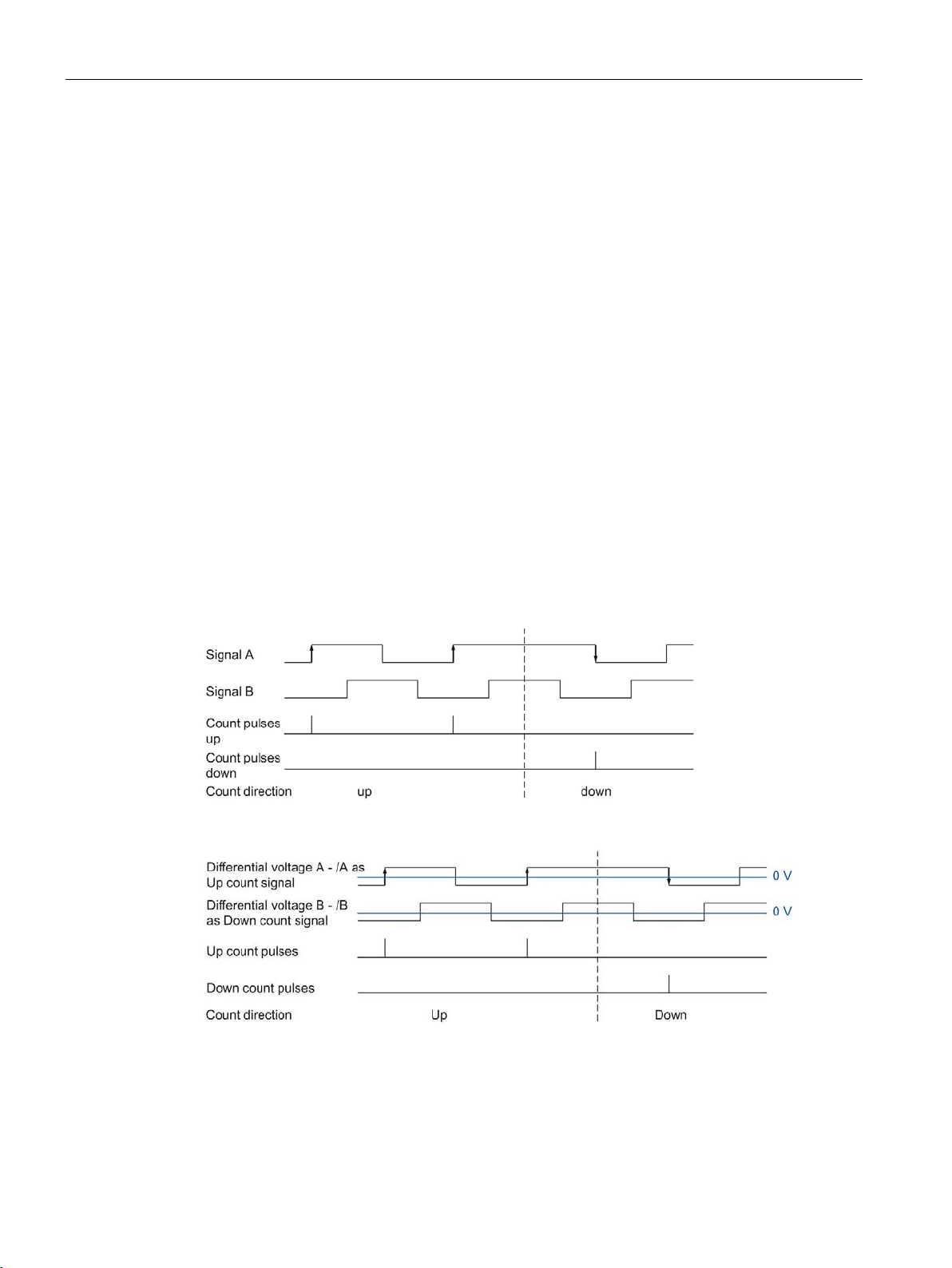
The basics of counting, measurement and position detection
2.2.14
Signal evaluation of incremental signals
2.2.14.1
Overview
2.2.14.2
Single evaluation
2.2 Basics of counting, measuring and position input (TM Count, TM PosInput, Compact CPU)
The technology module counter counts the edges of encoder signals A and B. For
incremental encoders with phase-shifted signals A and B, you can select either single or
multiple evaluation to improve the resolution.
You can configure the following signal evaluations:
● Single evaluation (Page 72)
● Double evaluation (Page 73)
● Quadruple evaluation (Page 74)
Single evaluation evaluates the rising and falling edge at signal A when signal B has a low
level.
Count pulses in an upwards direction are generated with a rising edge at signal A during a
low level at signal B. Count pulses in a downwards direction are generated with a falling
edge at signal A during a low level of signal B.
The following figure shows an example for single evaluation of 24 V and TTL count signals:
The following figure shows an example for single evaluation of RS422 count signals:
Counting, measurement and position detection
72 Function Manual, 12/2017, A5E32009889-AG
Page 74
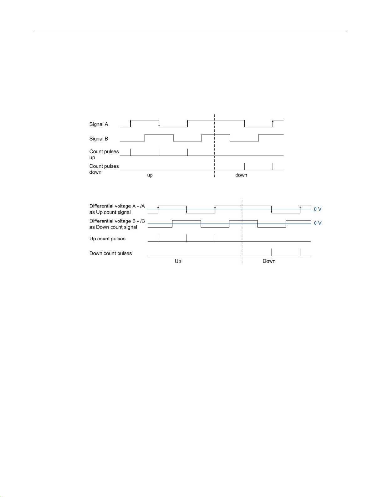
The basics of counting, measurement and position detection
2.2.14.3
Double evaluation
2.2 Basics of counting, measuring and position input (TM Count, TM PosInput, Compact CPU)
With double evaluation, the rising and falling edges of signal A are evaluated.
The edge direction of signal A and the level at signal B determines whether count pulses are
generated in an upward or downward direction.
The following figure shows an example for double evaluation of 24 V and TTL count signals:
The following figure shows an example for double evaluation of RS422 count signals:
Counting, measurement and position detection
Function Manual, 12/2017, A5E32009889-AG
73
Page 75
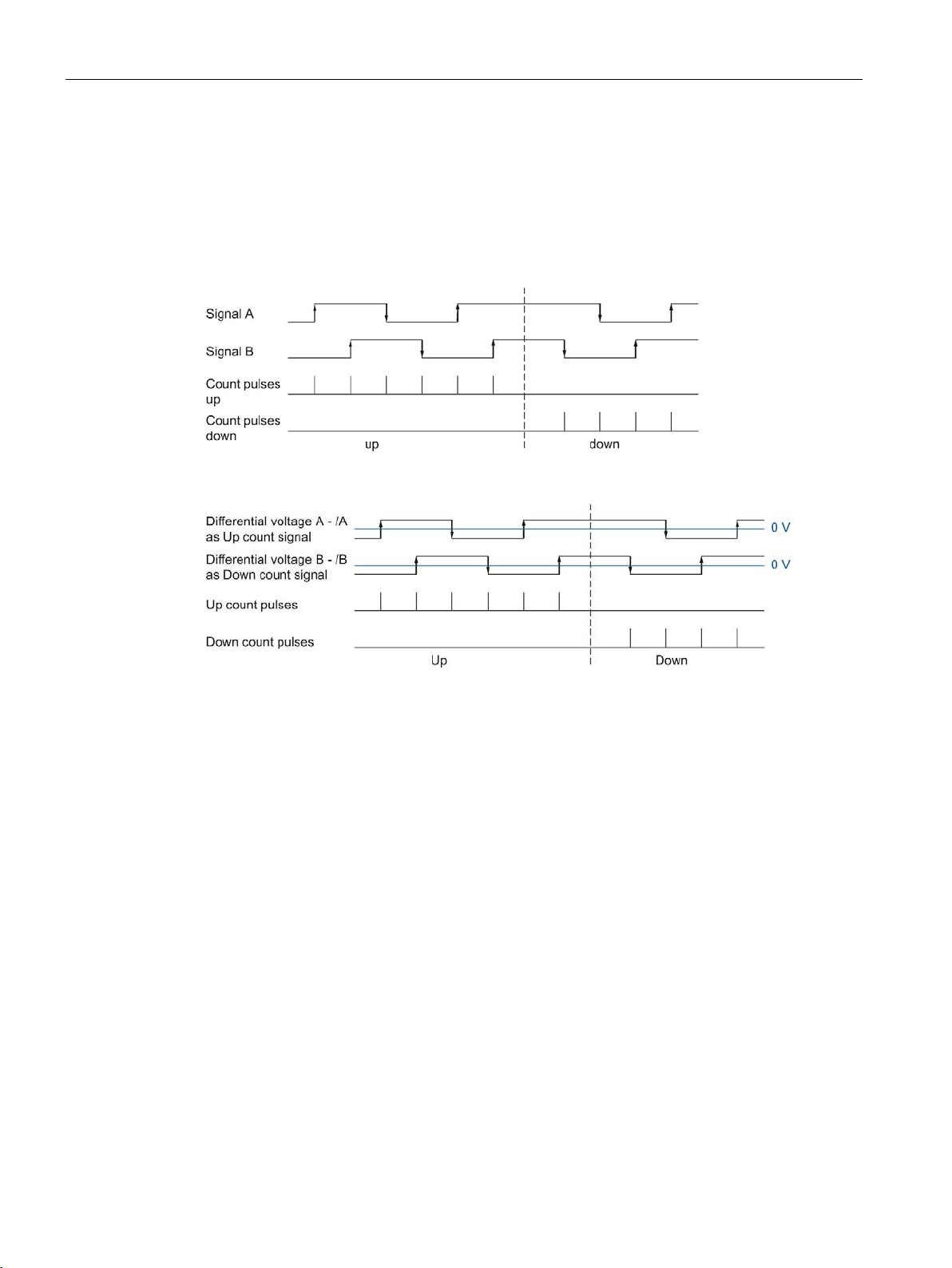
The basics of counting, measurement and position detection
2.2.14.4
Quadruple evaluation
2.2 Basics of counting, measuring and position input (TM Count, TM PosInput, Compact CPU)
With quadruple evaluation, the rising and falling edges of signals A and B are evaluated.
The edge direction of one signal and the level of the other signal determines whether count
pulses are generated in an upward or downward direction.
The figure below shows an example for quadruple evaluation of 24 V and TTL count signals:
The figure below shows an example for quadruple evaluation of RS422 count signals:
Counting, measurement and position detection
74 Function Manual, 12/2017, A5E32009889-AG
Page 76

The basics of counting, measurement and position detection
2.2.15
Clock synchronization (TM Count and TM PosInput)
Data processing
Additional information
2.2 Basics of counting, measuring and position input (TM Count, TM PosInput, Compact CPU)
The technology module supports the "isochronous mode" system function in distributed
mode. This system function enables position, count and measured values to be recorded in
a defined system cycle.
In isochronous mode, the cycle of the user program, the transmission of the input and output
data and the processing in the module are synchronized with each other. The output signals
switch immediately if the relevant comparison condition is met. A change in the state of a
digital input immediately affects the planned reaction of the technology module and changes
the status bit of the digital input in the feedback interface.
The data that was transmitted to the technology module in the current bus cycle via the
control interface takes effect when it is processed in the internal technology module cycle.
The position or counter value and the measured value and the status bits as well are
captured at the time T
current bus cycle.
For a detailed description of isochronous mode, refer to the PROFINET with STEP 7 function
manual, which is available as download at Internet
(https://support.industry.siemens.com/cs/ww/en/view/49948856).
and made available in the feedback interface for retrieval in the
i
Counting, measurement and position detection
Function Manual, 12/2017, A5E32009889-AG
75
Page 77

The basics of counting, measurement and position detection
2.3
Basics of counting (TM Timer DIDQ)
2.3.1
Overview of applications
Introduction
System environment
Applications
Components required
Configuration software
In the user program
Note
A description of the control and feedback interface is available in the device manual for the
TM Timer DIDQ.
2.3 Basics of counting (TM Timer DIDQ)
You configure the TM Timer DIDQ and assign its parameters with the configuration software.
The module's functions are controlled and monitored via the user program.
The respective module can be used in the following system environments:
Central operation with a
S7-1500 CPU or ET 200SP
CPU
Distributed operation with a
S7-1500 CPU
Distributed operation with a
S7-300/400 CPU
Distributed operation in a
third-party system
• S7-1500 Automation
System or ET 200SP Distributed I/O System
• TM Timer DIDQ
• S7-1500 Automation
System
• ET 200 Distributed I/O
System
• TM Timer DIDQ
• S7-300/400 automation
system
• ET 200 distributed I/O
system
• TM Timer DIDQ
• Third-party automation
system
• ET 200 distributed I/O
system
• TM Timer DIDQ
STEP 7 (TIA Portal) and
STEP 7:
Device configuration and
parameter setting with hardware configuration
Third-party configuration
software:
Device configuration and
parameter settings with GSD
file
Direct access to feedback
interface of the technology
module in the I/O data
Counting, measurement and position detection
76 Function Manual, 12/2017, A5E32009889-AG
Page 78

The basics of counting, measurement and position detection
2.3.2
Counting with incremental encoder
Count direction
Counting limits
Parameter assignment
Note
Counters of the TM Timer DIDQ 16x24V
The number of available counters of the TM Timer DIDQ 16x24V is dependent on the
channel configuration. In order to use 4 counters, you
channel configuration. If you choose the use of 3 inputs, you can use 1 counter. Other
channel configurations do not allow any counter use.
Counter value feedback
2.3 Basics of counting (TM Timer DIDQ)
You can use a few channels of a TM Timer DIDQ for simple counting tasks with an
incremental encoder. Counting refers to the recording and adding up of events. The
channels configured as counters each acquire the two incremental signals and evaluate
these accordingly.
The technology module can count up and down with an incremental encoder. You change
the count direction by inverting it.
The counting limits define the counter value range used.
The minimum counter value is -2147483648 (-2
31
2147483647 (2
-1). The respective counter counts continuously. At an overflow, the counter
jumps to the other counting limit in each case and continues counting.
The counter value cannot be influenced by the user program.
31
). The maximum counter value is
For use of a counter for an incremental encoder, two digital inputs each of a channel group
are combined. For this purpose, you choose the configuration "Incremental encoder (A, B
phase-shifted)" in the channel parameters for the respective group.
The current counter value is indicated in the feedback interface in the TEC_IN value (DIm).
DIm corresponds to the first of the two grouped digital inputs in each case. For the second
digital input, "0" is returned in the value TEC_IN (DIm+1).
must choose the use of 8 inputs in the
Counting, measurement and position detection
Function Manual, 12/2017, A5E32009889-AG
77
Page 79

The basics of counting, measurement and position detection
2.3.3
Counting with pulse encoder
Count direction
Counting limits
Parameter assignment
Note
Counters of the TM Timer DIDQ 16x24V
The number of available counters of the TM Timer DIDQ 16x24V is dependent on the
channel configuration. In order to use 4 counters, you must choose the use of 8 inputs in the
channel configuration. If you choose
channel configurations do not allow any counter use.
Counter value feedback
2.3 Basics of counting (TM Timer DIDQ)
You can use a few channels of a TM Timer DIDQ for simple counting tasks with a pulse
encoder. Counting refers to the recording and adding up of events. The channels configured
as counters each acquire one pulse signal and evaluate this accordingly.
The technology module can count up and down with a pulse encoder.
The counting limits define the counter value range used.
The minimum counter value is -2147483648 (-2
31
2147483647 (2
-1). The respective counter counts continuously. At an overflow, the counter
jumps to the other counting limit in each case and continues counting.
The counter value cannot be influenced by the user program.
31
). The maximum counter value is
For use of a counter for a pulse encoder, you choose the configuration "Use inputs
individually" or "Use input/output individually" in the channel parameters for the respective
group. You can configure the first digital input of a group as a counter.
The current counter value is indicated in the feedback interface in the TEC_IN value (DIm).
DIm corresponds to the respective digital input.
the use of 3 inputs, you can use 1 counter. Other
Counting, measurement and position detection
78 Function Manual, 12/2017, A5E32009889-AG
Page 80
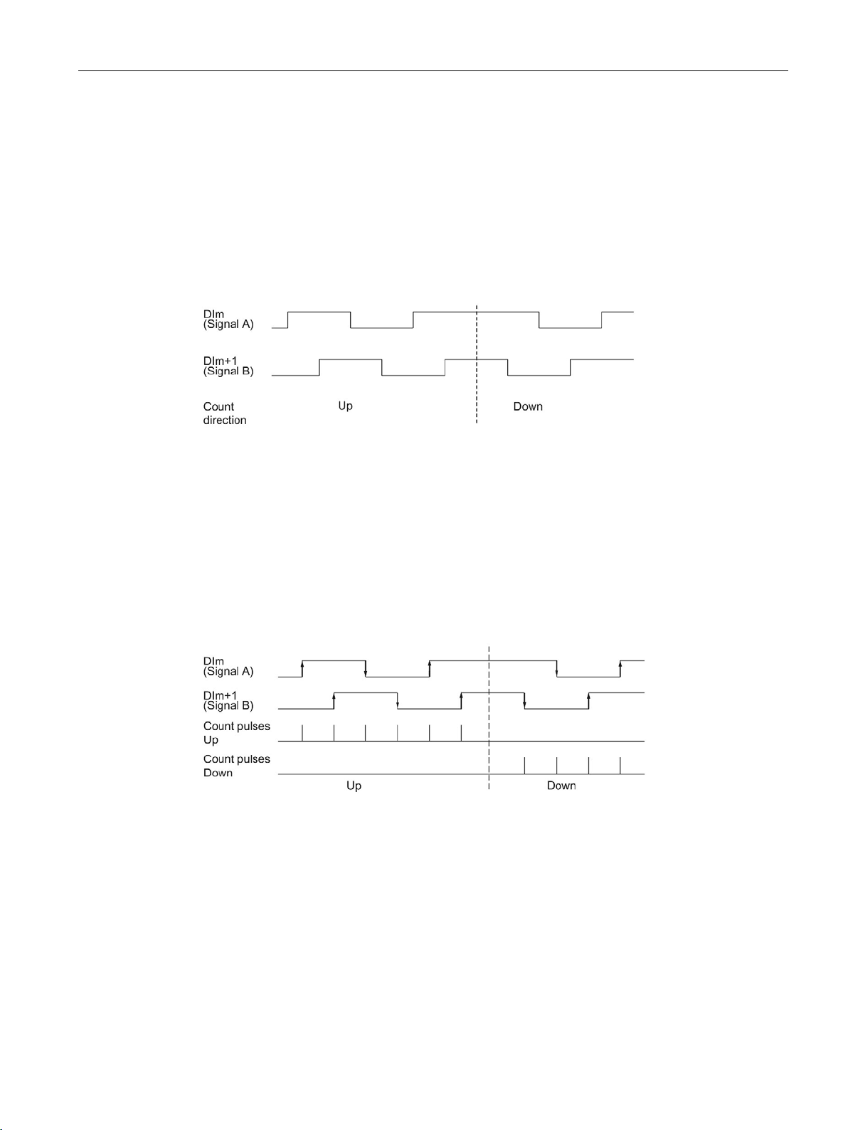
The basics of counting, measurement and position detection
2.3.4
24 V count signals
Count signals of 24 V incremental encoders
Signal evaluation
Count signals of 24 V pulse encoders
2.3 Basics of counting (TM Timer DIDQ)
The 24 V incremental encoder returns the 24 V signals A and B to the technology module.
The A and B signals are phase-shifted by 90°.
The figure below shows an example of the time profile of the signals of an 24 V incremental
encoder:
The technology module detects the count direction by evaluating the sequence of edges of
the A and B signals. You can specify an inversion of the count direction.
The two phase-shifted signals of an incremental encoder are evaluated four times. With
quadruple evaluation, the positive and negative edges of signal A and signal B are
evaluated.
Whether count pulses are generated in an upward or downward direction depends on the
edge direction of the one signal and the level of the other signal in the meantime.
The figure below shows an example of the quadruple evaluation of 24 V count signals:
The encoder, for example, a proximity switch (BERO) or a light barrier, returns only a count
signal that is connected to the digital input of a counter.
You can count the positive or the negative edges of the signal.
Counting, measurement and position detection
Function Manual, 12/2017, A5E32009889-AG
79
Page 81

The basics of counting, measurement and position detection
2.3.5
Isochronous mode
Data processing
Additional information
2.3 Basics of counting (TM Timer DIDQ)
The TM Timer DIDQ supports the "Isochronous mode" system function in decentralized
operation. This system function enables counter values to be acquired in a defined system
cycle.
In isochronous mode, the cycle of the user program, the transmission of the input and output
data and the processing in the module are synchronized with each other.
The data that was transmitted to the module in the current bus cycle via the control interface
takes effect when it is processed in the module's internal cycle. The counter value and status
bits are detected at time T
current bus cycle.
and made available in the feedback interface for retrieval in the
i
For a detailed description of isochronous mode, refer to the PROFINET with STEP 7 function
manual, which is available as download at Internet
(https://support.industry.siemens.com/cs/ww/en/view/49948856).
Counting, measurement and position detection
80 Function Manual, 12/2017, A5E32009889-AG
Page 82

The basics of counting, measurement and position detection
2.4
Basics of counting (digital input modules)
2.4.1
Overview of applications
Introduction
System environment
Applications
Components required
Configuration software
In the user program
Note
A description of the control and feedback interface is available in the device manual for the
digital input module.
2.4 Basics of counting (digital input modules)
The digital input module is configured and assigned parameters using the configuration
software.
The module's functions are controlled and monitored via the user program.
The respective module can be used in the following system environments:
Central operation with a
S7-1500 CPU or
ET 200SP CPU
Distributed operation with a
S7-1500 CPU
Distributed operation with a
S7-300/400 CPU
Distributed operation in a
third-party system
• S7-1500 Automation
System or ET 200SP Distributed I/O System
• Digital input module
• S7-1500 Automation
System
• ET 200 Distributed I/O
System
• Digital input module
• S7-300/400 automation
system
• ET 200 distributed I/O
system
• Digital input module
• Third-party automation
system
• ET 200 distributed I/O
system
• Digital input module
STEP 7 (TIA Portal) and
STEP 7:
Device configuration and
parameter setting with hardware configuration
Third-party configuration
software:
Device configuration and
parameter settings with
GSD file
Direct access to technology
module control and feedback
interface in the I/O data
Counting, measurement and position detection
Function Manual, 12/2017, A5E32009889-AG
81
Page 83

The basics of counting, measurement and position detection
2.4.2
Counting with pulse encoders
Counter limits
Start value
Gate control
2.4 Basics of counting (digital input modules)
Counting refers to the detection and summation of events. The modules' counters record and
evaluate pulse signals. The counting direction can be specified using encoder or pulse
signals or through the configuration.
You can use feedback bits to switch the digital outputs of digital output modules exactly at
defined counter values, independent of the user program.
You can configure the characteristics of the counters using the functionalities described
below.
The counter limits define the counter value range used. The counter limits are configurable
and can be modified during runtime using the user program. See the module's device
manual for the maximum and minimum configurable counter limits.
You can configure whether the counting processes are terminated or continue when a
counter limit is violated (automatic gate stop).
You can configure a start value within the counter limits. The start value can be modified
during runtime with the user program.
Opening and closing the hardware gate and software gate defines the period of time during
which the counting signals are recordd.
The hardware gate is controlled externally via a digital input of the technology module. The
hardware gate can be enabled through parameter assignment. The software gate is
controlled via the user program. A description of the control and feedback interface is
available in the device manual for the digital input module.
Counting, measurement and position detection
82 Function Manual, 12/2017, A5E32009889-AG
Page 84
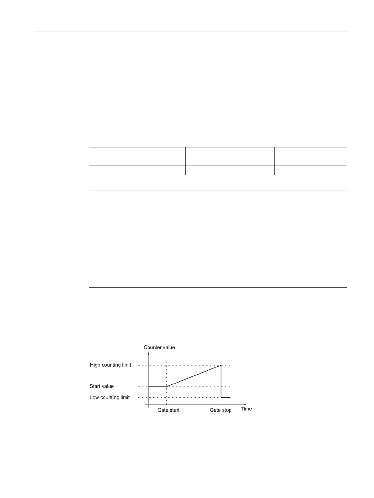
The basics of counting, measurement and position detection
2.4.3
Behavior at the counting limits
Violation of a counting limit
Counting limit violated
Event bit
Reset bit
High counting limit
EVENT_OFLW
RES_EVENT_OFLW
Note
A description of the control and feedback interface is available in the device manual for the
digital input module.
Note
The high counting limit and the start value define the value range of the counter:
Value range of the counter = (high limit
Examples
2.4 Basics of counting (digital input modules)
The high counting limit is violated when the current counter value is equal to the high
counting limit and another upward count pulse is received. The counter low limit is violated
when the current counter value is equal to the counter low limit and another downward count
pulse is received.
With digital input modules for ET 200SP, the corresponding event bit is set in the feedback
interface when the limit is violated. You can reset an event bit with the respective control bit:
Low counting limit EVENT_UFLW RES_EVENT_UFLW
You can configure whether or not you want to continue counting to another counter limit after
a counting limit violation.
– start value) + 1
The figure below shows an example for terminating counting after overflow and setting the
counter to the opposite counting limit:
Counting, measurement and position detection
Function Manual, 12/2017, A5E32009889-AG
83
Page 85
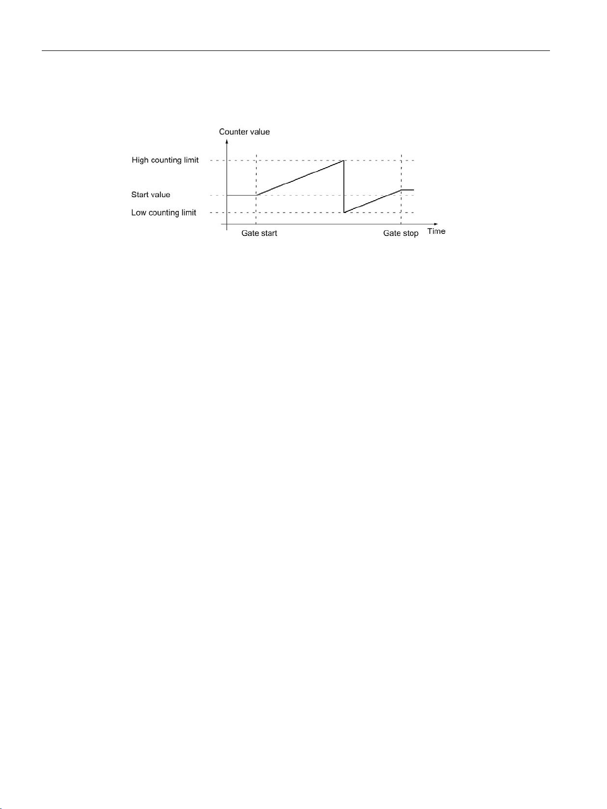
The basics of counting, measurement and position detection
2.4 Basics of counting (digital input modules)
The figure below shows an example for continuing the counting process after an overflow
and setting the counter to the opposite counting limit:
Counting, measurement and position detection
84 Function Manual, 12/2017, A5E32009889-AG
Page 86
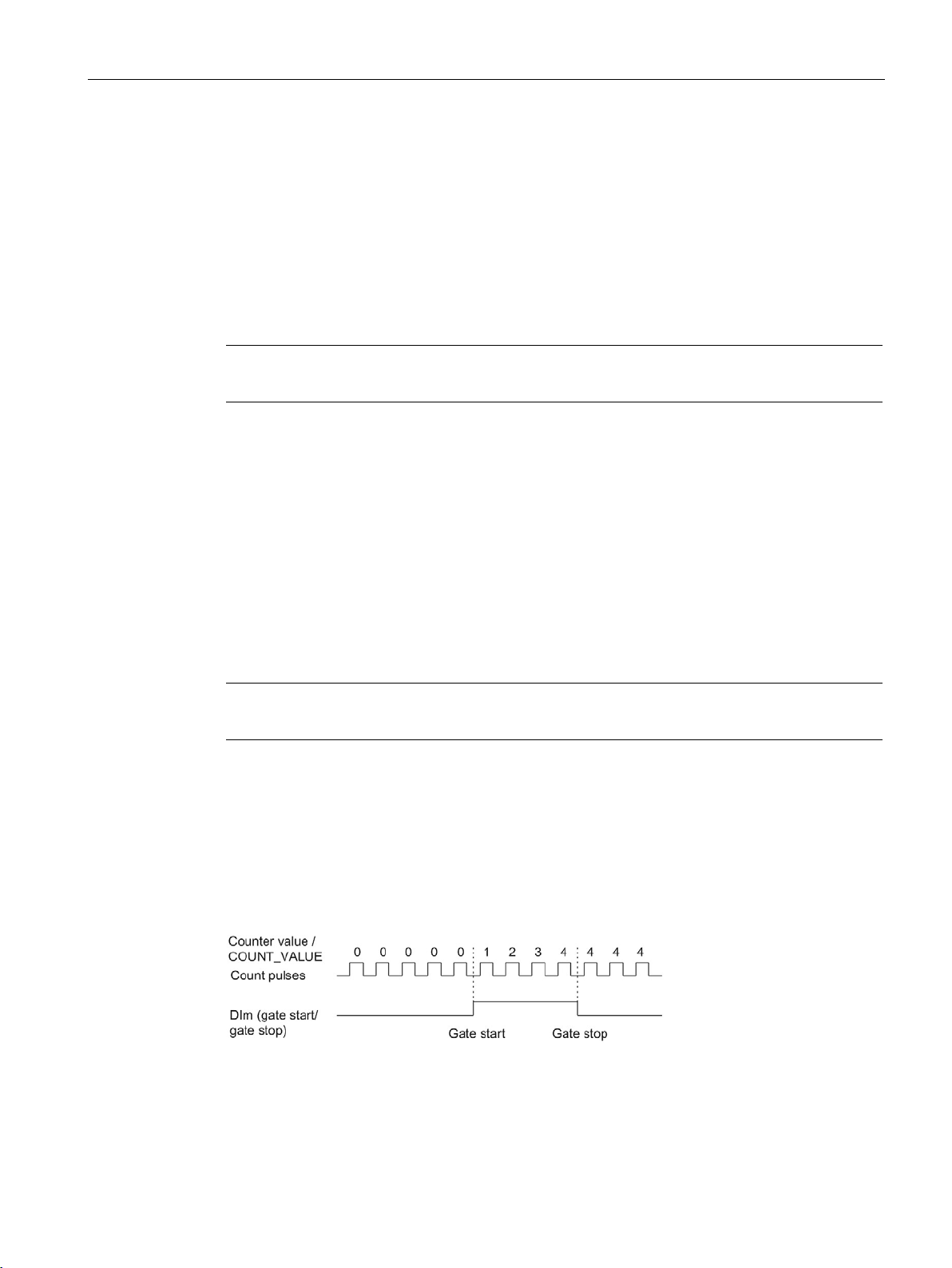
The basics of counting, measurement and position detection
2.4.4
Gate control
Note
The hardware gate is not configurable for all digital input modules.
2.4.4.1
Software gate
2.4.4.2
Hardware gate
Note
A configurable input delay delays the control signal of the digital input.
Opening and closing the hardware gate
2.4 Basics of counting (digital input modules)
Many applications require counting processes to be started or stopped in accordance with
other events. In such cases, counting is started and stopped using the gate function.
The digital input modules have two gates for each counting channel. These define the
resulting internal gate:
● Software gate
● Hardware gate
The software gate of the channel is opened and closed with the SW_GATEcontrol bit.
See the module's device manual for information on the design of the control and feedback
interface.
The hardware gate is optional. You open and close the hardware gate using signals at the
corresponding digital input.
The status of a DIm digital input is indicated by the respective STS_DIm feedback bit. A
description of the control and feedback interface is available in the device manual for the
digital input module.
The figure below shows an example of opening and closing with a digital input:
As long as the digital input is set, the hardware gate is open and the count pulses are
counted. The hardware gate is closed when the digital input is reset. The counter value stays
constant and ignores any further count pulses.
Counting, measurement and position detection
Function Manual, 12/2017, A5E32009889-AG
85
Page 87
The basics of counting, measurement and position detection
2.4.4.3
Internal gate
Internal gate
Hardware gate
Software gate
Internal gate
Open/not configured
open
open
Open/not configured
closed
closed
closed
open
closed
2.4 Basics of counting (digital input modules)
The internal gate is open if the software gate is open and the hardware gate is open or has
not been configured. The status of the internal gate is indicated by the STS_GATE feedback
bit. See the module's device manual for information on the design of the control and
feedback interface.
If the internal gate is open, counting is started. If the internal gate is closed, all other count
pulses are ignored and counting is stopped.
If you want to control a counting process with the hardware gate only, the software gate must
be open. If you do not configure a hardware gate, the hardware gate is considered to be
always open. In this case, you open and close the internal gate with the software gate only.
closed closed closed
The internal gate can also be automatically closed upon violation of a counting limit. The
software or hardware gate must then be closed and reopened to continue counting.
Counting, measurement and position detection
86 Function Manual, 12/2017, A5E32009889-AG
Page 88
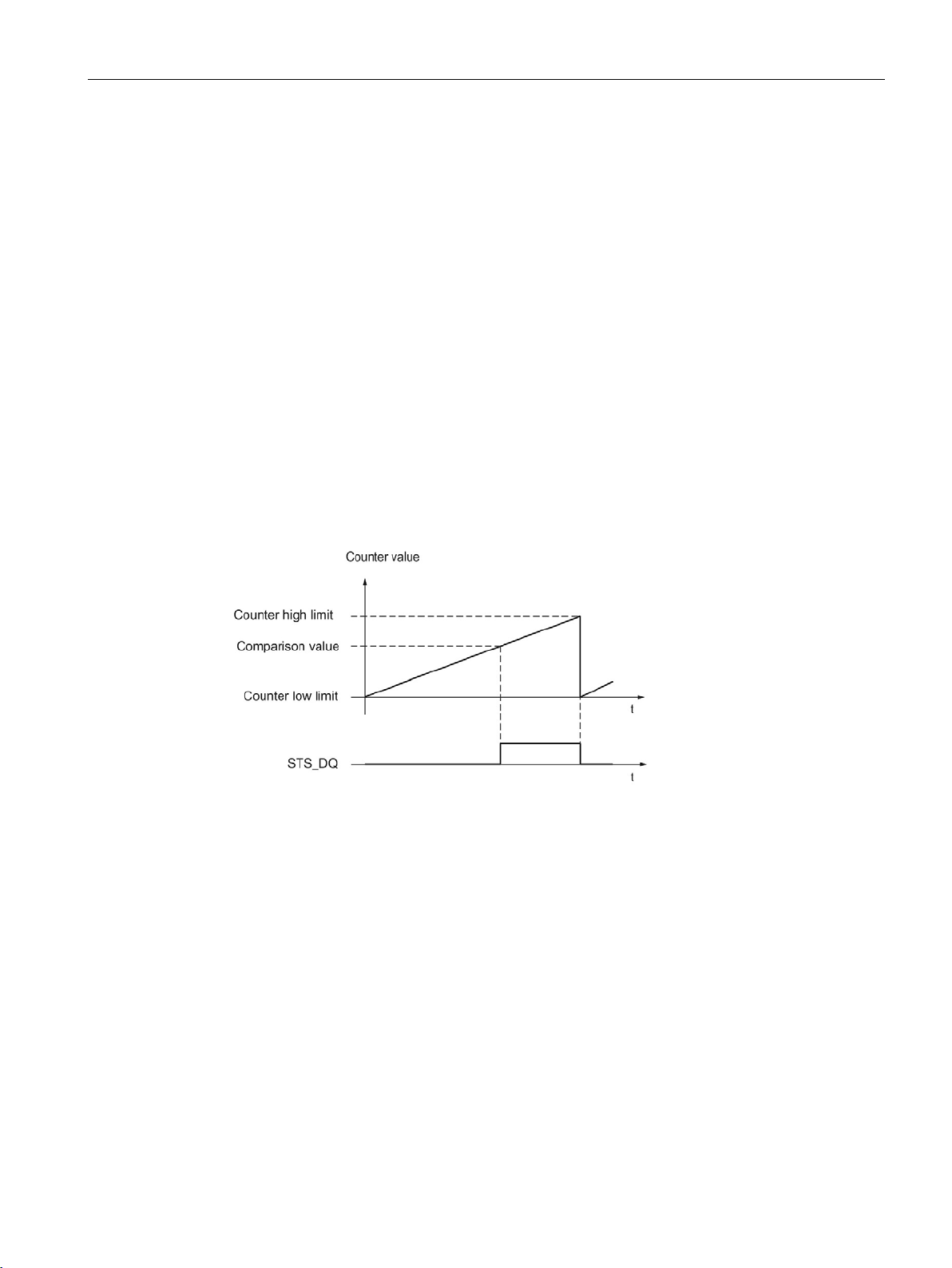
The basics of counting, measurement and position detection
2.4.5
Comparison values
Setting between comparison value and high counter limit
2.4 Basics of counting (digital input modules)
Depending on the module, you can define up to two comparison values that control a reset
bit for the channel, independent of the user program.
When there are two comparison values, comparison value 1 must be greater than
comparison value 0. The comparison values are configurable and can be changed at runtime
by the user program.
The comparison values are compared with the current counter value. If the counter value
meets the configured comparison condition, the respective STS_DQ reset bit is set.
You can use the respective reset bit in order to switch a digital output module's digital output.
You can make setting the respective STS_DQ reset bit dependent on one of the following
comparison events. See the device manual for the technology module to find out which
comparison events can be configured.
The respective STS_DQ feedback bit is set to 1 when:
Comparison value <= counter value <= high counter limit
Counting, measurement and position detection
Function Manual, 12/2017, A5E32009889-AG
87
Page 89
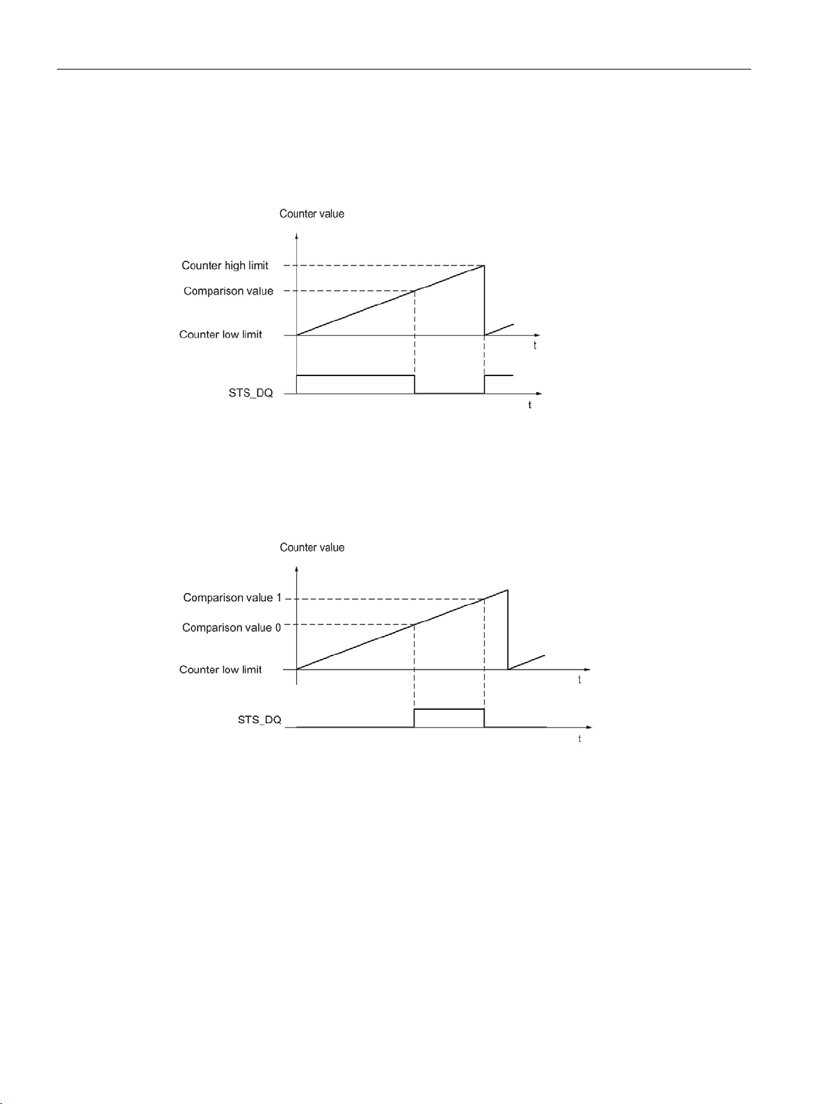
The basics of counting, measurement and position detection
Setting between comparison value and low counter limit
Setting between comparison value 0 and comparison value 1
2.4 Basics of counting (digital input modules)
The respective STS_DQ feedback bit is set to 1 when:
Low counter limit <= counter value <= comparison value
The respective STS_DQ feedback bit is set to 1 when:
Comparison value 0 <= counter value <= comparison value 1
Counting, measurement and position detection
88 Function Manual, 12/2017, A5E32009889-AG
Page 90
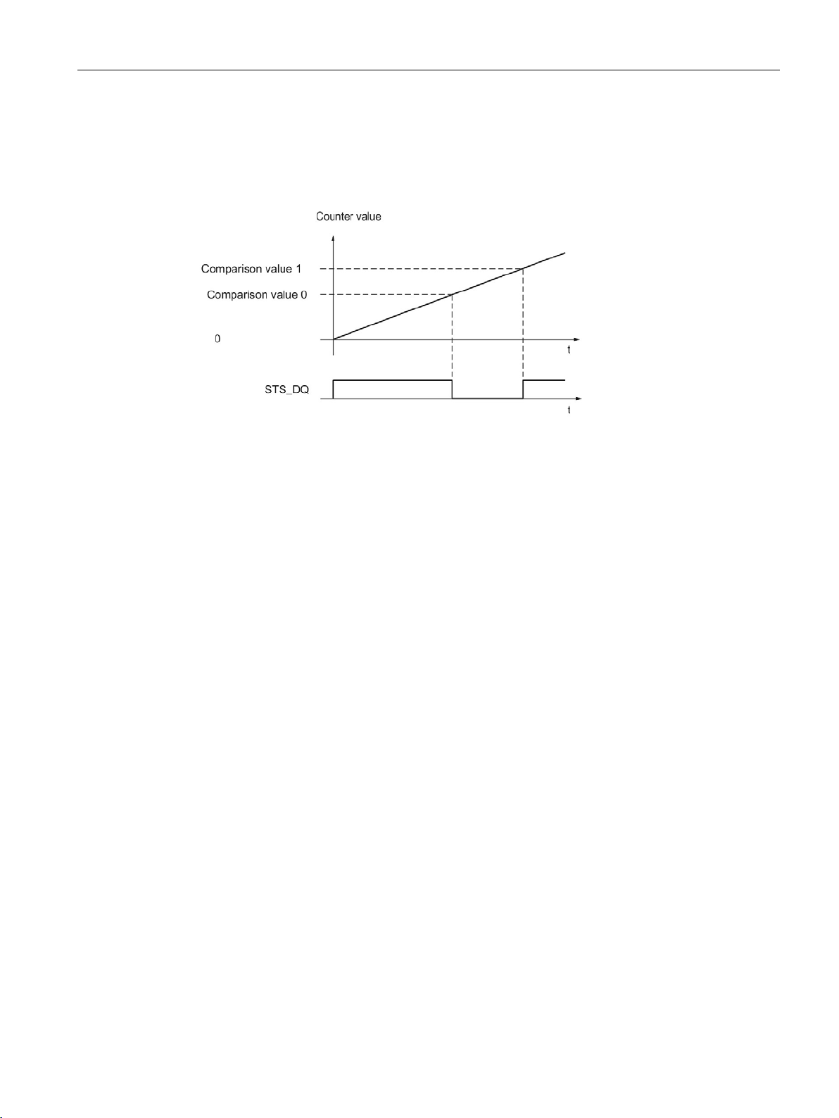
The basics of counting, measurement and position detection
Not setting between comparison value 0 and comparison value 1
2.4 Basics of counting (digital input modules)
The respective STS_DQ feedback bit is set to 1 when:
Comparison value 0 <= counter value <= comparison value 1
Counting, measurement and position detection
Function Manual, 12/2017, A5E32009889-AG
89
Page 91
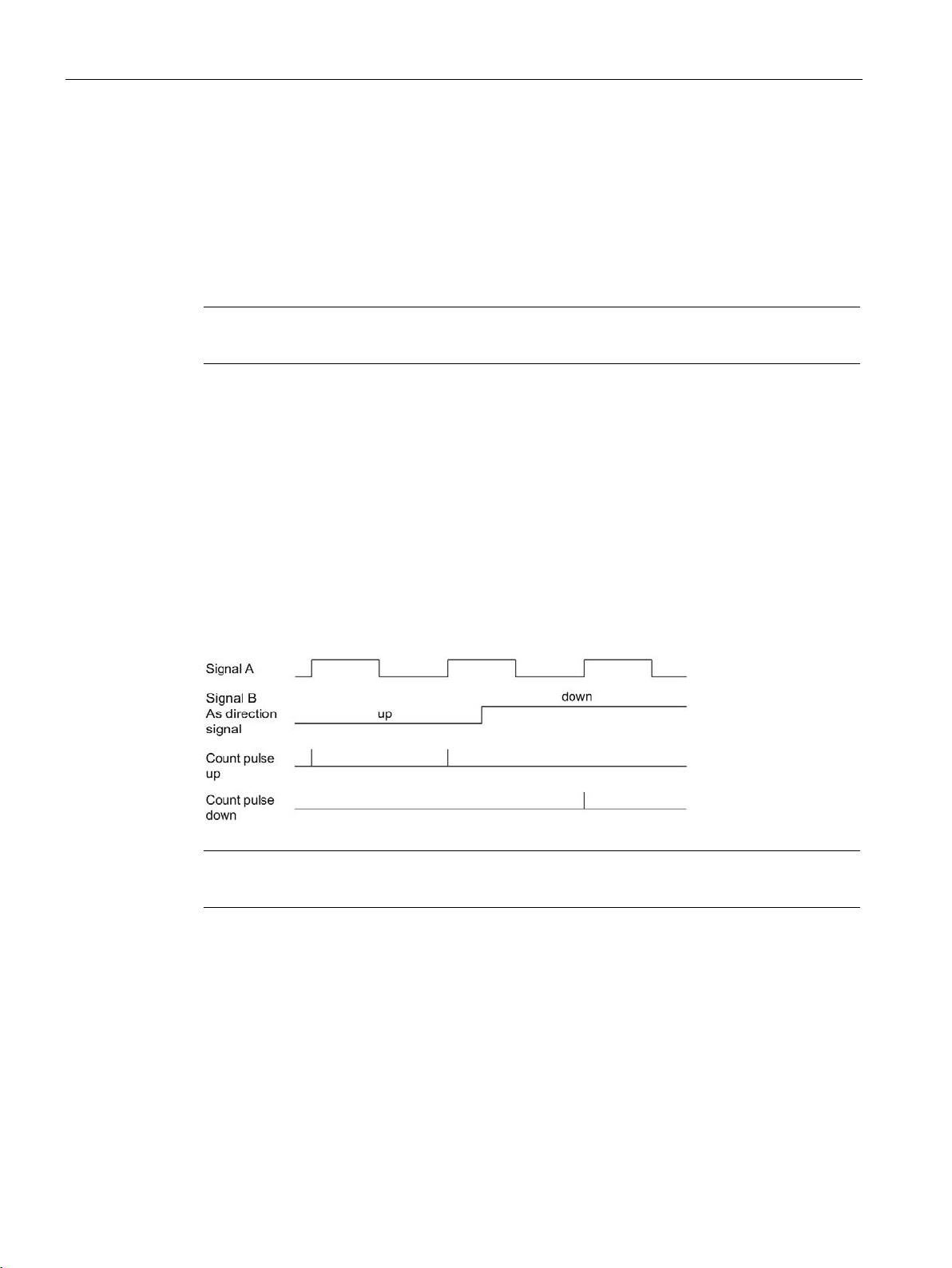
The basics of counting, measurement and position detection
2.4.6
Interrupts
Hardware interrupt
Note
Hardware interrupts for counting are not configurable for all digital input modules.
2.4.7
24 V count signals
24 V pulse encoder count signals
Note
A signal for direction detection cannot be connected for all digital input modules.
Monitoring of encoder signals
2.4 Basics of counting (digital input modules)
The module can trigger a hardware interrupt in the CPU during operation for certain events.
The hardware interrupts can be enabled in the configuration. Refer to the device manual for
the module to learn about the events that can trigger a hardware interrupt during operation.
The encoder, for example an initiator (BERO) or a light barrier, returns a count signal that is
connected to the terminal (signal A) of the counter. You can also connect a signal for
direction detection (signal B).
The figure below shows an example of the time profile of the signals of a 24 V pulse encoder
with direction signal and the resulting count pulses:
If you enable the respective diagnostic interrupt in the device configuration, the module
triggers a diagnostic interrupt in the event of an encoder signal error.
Counting, measurement and position detection
90 Function Manual, 12/2017, A5E32009889-AG
Page 92

The basics of counting, measurement and position detection
2.4.8
Isochronous mode
Data processing
Additional information
2.4 Basics of counting (digital input modules)
The digital input module supports the "isochronous mode" system function in distributed
mode. This system function enables counter values to be acquired in a defined system cycle.
In isochronous mode, the cycle of the user program, the transmission of the input and output
data and the processing in the module are synchronized with each other.
The data that was transmitted to the module in the current bus cycle via the control interface
takes effect when it is processed in the module's internal cycle. The counter value and status
bits are detected at time T
current bus cycle.
and made available in the feedback interface for retrieval in the
i
For a detailed description of isochronous mode, refer to the PROFINET with STEP 7 function
manual, which is available as download at Internet
(https://support.industry.siemens.com/cs/ww/en/view/49948856).
Counting, measurement and position detection
Function Manual, 12/2017, A5E32009889-AG
91
Page 93

3
3.1
Convention
Technology module
3.2
High_Speed_Counter technology object
Operating mode
technology modules TM Count and TM PosInput and the technology component of the
compact CPUs.
STEP 7 (TIA Portal) supports you in the configuration, commissioning and diagnostics of
counting and measuring functions for the following technology modules with the "Technology
objects" function:
● You configure the High_Speed_Counter technology object in STEP 7 (TIA Portal) with the
settings for the counting and measuring functions.
● The corresponding High_Speed_Counter instruction is programmed in the user program.
This instruction supplies the control and feedback interface of the technology module.
The High_Speed_Counter technology object corresponds to the instance DB of the
High_Speed_Counter instruction. The configuration of the counting and measuring functions
is saved in the technology object. The technology object is located in the folder "PLC >
Technology objects".
The High_Speed_Counter technology object can be used for technology modules of both the
S7-1500 and ET 200SP systems.
: We use the term "technology module" in this documentation both for the
In order to assign the technology module parameters using the technology object, you
specify the operating mode (Page 174) "Operating with "Counting and measurement"
technology object" in the hardware configuration of the technology module. This selection is
already preset.
Counting, measurement and position detection
92 Function Manual, 12/2017, A5E32009889-AG
Page 94

Using the High_Speed_Counter technology object
3.3
Overview of the configuration steps
Introduction
Requirement (TM Count and TM PosInput)
Requirement (Compact CPU)
Procedure
Step
Description
1
Configure a technology module (Page 169)
3
Configure a technology object according to your application (Page 96)
4
Call instruction in the user program (Page 118)
5
Load to CPU
6
Commissioning the technology object (Page 132)
7
Diagnostics of the technology object (Page 134)
3.3 Overview of the configuration steps
The overview below shows the basic procedure for configuring the counting and measuring
functions of the technology module with the High_Speed_Counter technology object.
Before you can use the High_Speed_Counter technology object, a project with an S7-1500
CPU or an ET 200SP CPU must be created in STEP 7 (TIA Portal) .
Before you can use the High_Speed_Counter technology object, a project with a Compact
CPU S7-1500 must be created in STEP 7 (TIA Portal).
Proceed in the recommended sequence outlined below:
2 Add technology object (Page 94)
Counting, measurement and position detection
Function Manual, 12/2017, A5E32009889-AG
93
Page 95

Using the High_Speed_Counter technology object
3.4
Add technology object
Add technology object in the project navigator
Requirement (TM Count and TM PosInput)
Requirement (Compact CPU)
Procedure
3.4 Add technology object
When a technology object is added, an instance DB is created for the instruction of this
technology object. The configuration of the technology object is stored in this instance DB.
A project with a CPU S7-1500 has been created.
A project with a Compact CPU S7-1500 has been created.
To add a technology object, proceed as follows:
1. Open the CPU folder in the project tree.
2. Open the "Technology objects" folder.
3. Double-click on "Add new object".
The "Add new object" dialog opens.
4. Select the "Counting and measurement" technology.
5. Select the "High_Speed_Counter" object.
6. Enter an individual name for the technology object in the "Name" text box.
7. Click "Additional information" if you want to add your own information to the technology
object.
8. Confirm with "OK".
Counting, measurement and position detection
94 Function Manual, 12/2017, A5E32009889-AG
Page 96
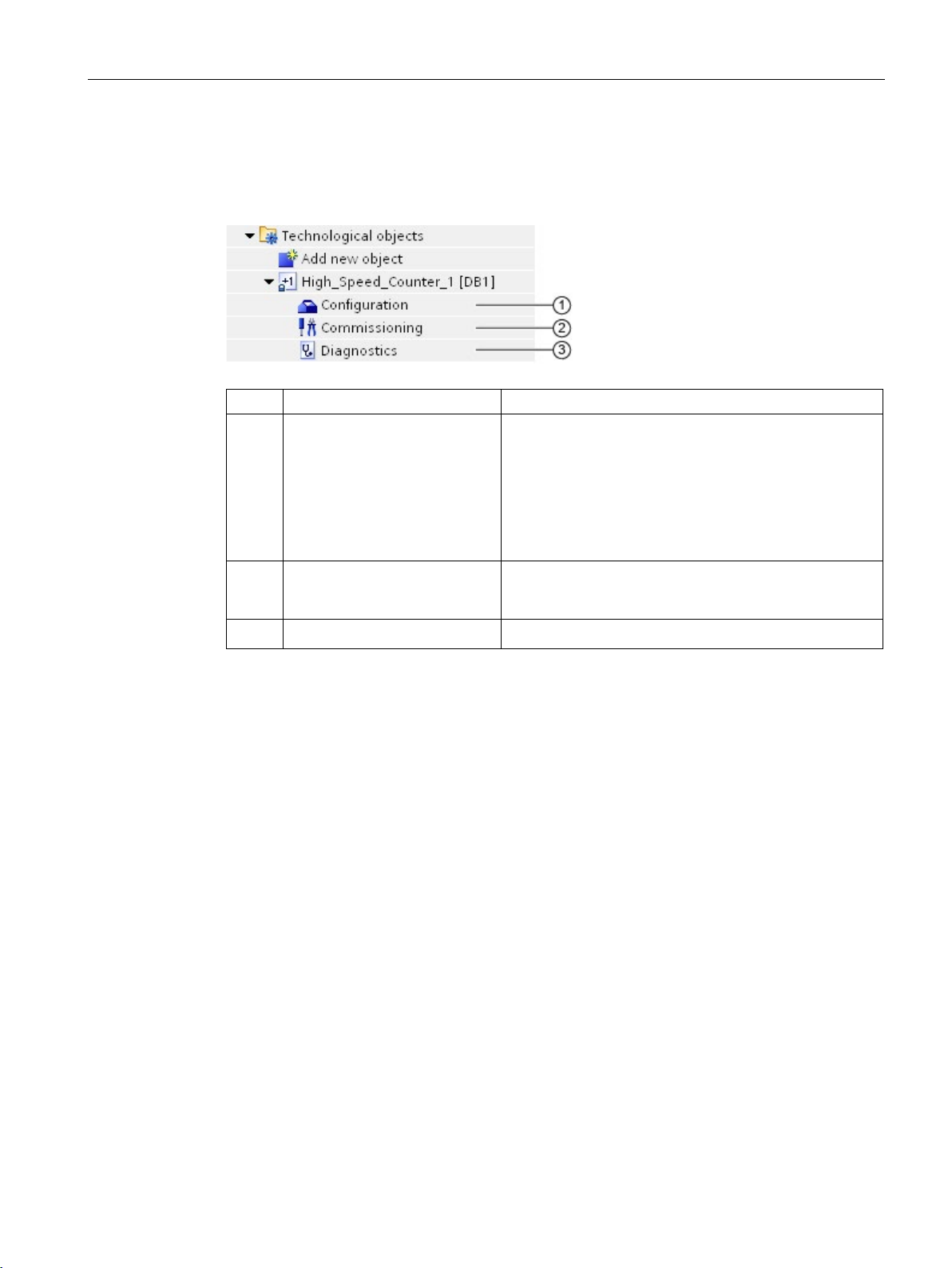
Using the High_Speed_Counter technology object
Result
Object
Description
Technology object parameter settings for counting and
and
hardware configuration to the CPU.
②
struction and monitoring the effects
3.4 Add technology object
The new technology object has now been created and stored in the project tree in the
"Technology objects" folder.
①
③
Configuration (Page 96) In the configuration dialog:
• Assignment of technology module and channel
•
measurement functions
When you change the configuration of the technology
object, you must download the technology object
Commissioning (Page 132) Commissioning and function test of the technology object:
Diagnostics (Page 134) Monitoring the counting and measuring functions
Simulating parameters of the High_Speed_Counter in-
the
Counting, measurement and position detection
Function Manual, 12/2017, A5E32009889-AG
95
Page 97
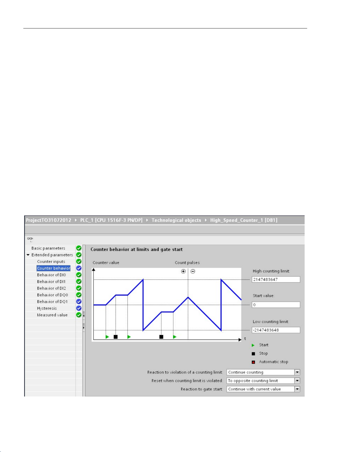
Using the High_Speed_Counter technology object
3.5
Configuring the High_Speed_Counter
3.5.1
Working with the configuration dialog
Basic parameters
Extended parameters
3.5 Configuring the High_Speed_Counter
You configure the properties of the technology object in the configuration window. Proceed
as follows to open the configuration window of the technology object:
1. Open the "Technology objects" folder in the project tree.
2. Open the technology object in the project tree.
3. Double-click on the "Configuration" object.
The configuration is divided into the following categories:
●
The basic parameters include the selection of the technology module and the number of
the counting channel for which the technology object is configured.
●
The extended parameters include the parameters for adapting the counting and
measuring functions and for setting the characteristics of the digital inputs and digital
outputs.
Counting, measurement and position detection
96 Function Manual, 12/2017, A5E32009889-AG
Page 98
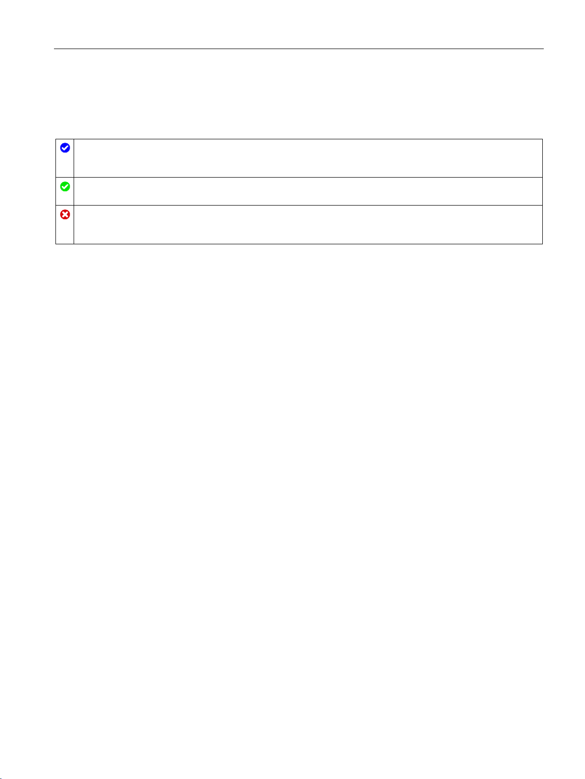
Using the High_Speed_Counter technology object
Configuration window icons
The configuration contains default values and is complete
additional changes.
The configuration contains values set by the user or automatically adapted values and is complete
All text boxes of the configuration contain valid values and at least one default value was changed.
The configuration is incomplete or incorrect
played on a red background. Click the roll-out error message to indicate the cause of error.
3.5 Configuring the High_Speed_Counter
Icons in the area navigation of the configuration show additional details about the status of
the configuration:
.
The configuration contains only default values. With these default values, you can use the technology object without
At least one text box or drop-down list contains an invalid value. The corresponding field or the drop-down list is dis-
Counting, measurement and position detection
Function Manual, 12/2017, A5E32009889-AG
97
Page 99

Using the High_Speed_Counter technology object
3.5.2
Basic parameters
Module (TM Count and TM PosInput)
Module (Compact CPU)
Channel
Note
A channel can be assigned to only
technology object. A channel that is already assigned
to a technology object can no longer be selected.
Synchronization of the parameter values
3.5 Configuring the High_Speed_Counter
You can establish the connection between the High_Speed_Counter technology object and
the technology module under "Basic parameters".
You select the technology module in a subsequent dialog box. All technology modules
(central or distributed) that are configured for use with a "Counting and measurement"
technology object under the S7-1500 CPU or ET 200SP CPU are available for selection.
After selecting the technology module, you can open the device configuration associated
with the technology module by clicking the"Device configuration" button.
The technology module parameter settings required for the use of the technology object are
made in the "Extended parameters" of the technology object.
You can select a high-speed counter for the Compact CPU in a subsequent dialog. You can
choose any of the high-speed counters which are enabled and configured for use with a
technology object from "Counting and measuring".
After selecting the high-speed counter, you can open the device configuration associated
with the Compact CPU by clicking the"Device configuration" button.
The parameter settings of the high-speed counter required for the use of the technology
object are made in the "Extended parameters" of the technology object.
For a technology module with several counting channels, you can also select the number of
the counting channel for which the High_Speed_Counter technology object is to be valid.
If, after assignment of the channel to the technology object, there is an inconsistency
between the parameter values under "Parameters" and in the technology object, a button
with a corresponding inquiry appears. When you click the button, the parameter values
under "Parameters" are overwritten by the parameter values of the technology object within
STEP 7 (TIA Portal). The current parameter values of the technology object are displayed
under "Parameters".
one
Counting, measurement and position detection
98 Function Manual, 12/2017, A5E32009889-AG
Page 100
Using the High_Speed_Counter technology object
3.5.3
Counter inputs (High_Speed_Counter)
Signal type
Symbol
Signal type
Meaning
Additional option-specific
parameters
Invert direction
3.5 Configuring the High_Speed_Counter
You can choose from the following signal types (Page 67):
Incremental encoder (A, B
phase-shifted)
Incremental encoder
(A, B, N)
Pulse (A) and direction (B) A pulse encoder (signal A) with direction
Pulse (A) A pulse encoder (signal A) without direction
An incremental encoder with phase-shifted A
and B signals is connected.
An incremental encoder with phase-shifted
signals A and B and a zero signal N is connected.
signal (signal B) is connected.
signal is connected. You can specify the
count direction by means of the control interface (Page 185).
• Invert direction
• Signal evaluation
• Filter frequency
• Sensor type or Interface
standard
• Invert direction
• Signal evaluation
• Filter frequency
• Sensor type or Interface
standard
• Reaction to signal N
• Frequency
• Filter frequency
• Sensor type or Interface
standard
• Filter frequency
• Sensor type or Interface
standard
Counting, measurement and position detection
Function Manual, 12/2017, A5E32009889-AG
Count up (A), count down
(B)
You can invert the counting direction to adapt it to the process.
The inverting of the direction is configurable and active for the following signal types:
● Incremental encoder (A, B phase-shifted)
● Incremental encoder (A, B, N)
Signals for counting up (signal A) and down
(signal B) are connected.
• Filter frequency
• Sensor type or Interface
standard
99
 Loading...