

Page 1

Important Information List of Safety Notes
Contents
SIMATIC
Programmable Controllers
S7 F/FH Systems
Manual
Product Overview
Getting Started
Safety Mechanisms
Configuration
Programming
Operation and Maintenance
Safety
Fail-Safe Function Blocks
Appendices
1
2
3
4
5
6
7
8
This manual is part of the documentation
package with the order number:
6ES7988-8FA10-8BA0
Edition 02/2003
A5E00085588-03
Check Lists
References
Glossary, Index
A
B
Page 2
Safety Guidelines
This manual contains notices intended to ensure personal safety, as well as to protect the products and
connected equipment against damage. These notices are highlighted by the symbols shown below and
graded according to severity by the following texts:
!
!
!
Safety Note
Contains important information on the acceptance and safety-related use of the product.
Warning
indicates that death, severe personal injury or substantial property damage can result if proper
precautions are not taken.
Caution
indicates that minor personal injury can result if proper precautions are not taken.
Note
draws your attention to particularly important information on the product, handl i ng the product , or to a
particular part of the documentation.
Qualified Personnel
Only qualified personnel should be allowed to install and work on this equipment. Qualified persons are
defined as persons who are authorized to commission, to ground and to tag circuits, equipment, and
systems in accordance with established safety practices and standards.
Correct Usage
Note the following:
!
Trademarks
Copyright © Siemens AG 2003 All rights reserved
The reproduction, transmission or use of this document or its
contents is not permitted without express written authority.
Offenders will be liable for damages. All rights, including rights
created by patent grant or registration of a utility model or design,
are reserved.
Siemens AG
Automation and Drives
Industrial Automation Systems
Postfach 4848, D- 90327 Nuern be rg
Siemens Aktiengesellschaft A5E00085588-03
This device and its components may only be used for the applications described in the catalog or the
technical description, and only in connection with devices or components f rom other manufacturers
which have been approved or recommended by Siemens.
This product can only function correctly and safely if it is transported, stored, s et up, and install ed
correctly, and operated and maintained as recommended.
SIMATIC®, SIMATIC HMI® and SIMATIC NET® are registered trademarks of SIEMENS AG.
Some of the other designations used in these documents are also registered trademarks; the owner’s rights
may be violated if they are used by third parties for their own purposes.
Disclaimer of Liability
We have checked t he contents of this manual for agreem ent with
the hardware and s oftware described. Since de viations cannot be
precluded entirel y, we cannot guarantee full a greement. However,
the data in this m anual are reviewed regul arly and any necessary
corrections included in subsequent editions. Suggestions for
improvement are welcom e d.
©Siemens AG 2003
Technical data subject to change.
Warning
Page 3

Important Information
Purpose of the Manual
The information contained in this manual enables you to configure and program S7
F/FH Systems using S7 F Systems V5.2.
Target Group
This manual is intended for system planners, configuration engineers and
programmers. Knowledge of STEP 7 and CFC is assumed in most areas.
Contents
This manual describes how to work with the S7 F/FH Systems using S7 F-Systems
V5.2 software. It consists of instructive chapters and reference chapters
(descriptions of the fail-safe function blocks and check lists for acceptance). The
manual covers the following topics:
• Safety Mechanisms
• Configuration
• Programming
• Maintenance
• Safety
• Fail-Safe Blocks
Scope of the Manual
The S7 F Systems V5.2
Options Package including
Authorization License V5.0
F-Copy License 6ES7 833 1CC00 6YX0 V5.0
Module Order Number As of Version
6ES7 833 1CC00 0YX0 V5.2
Fail-Safe Systems
A5E00085588-03 iii
Page 4
Important Information
What’s New?
The following changes are new in the S7 F Systems V5.2:
Topic Chapter
New Fail-Safe Blocks Fail-Safe Blocks
Introduction to the F_Shutdown Logic Getting Started
Support of the new ET 200S failsafe modules to the S7 F/FH
Systems
Enhanced usability Programming
Standards, Certificates and Approvals
The S7 FH System and the fail-safe F-I/O’s are certified for use in safety mode up
to the following levels:
Throughout the
document
• Requirement classes AK1 to AK6
DIN V VDE 0801
• SIL1 to SIL3 (Safety Integrity Level) in accordance with IEC 61508
• Categories 1 to 4 in accordance with EN 954-1
Place in the Information Landscape
This manual is part of the documentation package for the S7 F/FH System.
System Documentation Package Order Number
S7 F Systems • Safety Engineering in SIMATIC S7
• Programmable Controllers,
S7 F/FH Systems
• ET200 S Distributed I/O System Fail-
Safe Modules
• Automation Systems S7-300 Fail-Safe
Signal Modules
CD-ROM
in accordance with DIN V 19250/
6ES7988-8FB10-8BA0
You can also obtain all the SIMATIC S7 documentation as a dedicated SIMATIC
S7 collection on CD-ROM.
iv A5E00085588-03
Fail-Safe Systems
Page 5

How to Use this Manual
To help you find specific information quickly, the manual contains the following
aids:
• There is a complete table of contents at the beginning of the manual.
• A heading indicating the contents of each section is provided in the left-hand
column on each page of each chapter.
• Following the appendices, you will find a glossary in which important technical
terms used in the manual are defined.
• At the end of the manual you will find a detailed index, which makes it easy for
you to find the information you are looking for.
Additional Support
For any unanswered questions about the use of products presented in this manual,
contact your local Siemens representative:
http://www.siemens.com/automation/partner
Important Information
Training Center
We offer courses to help you get started with the S7 automation system. Contact
your regional training center or the central training center in Nuremberg (90327),
Federal Republic of Germany.
Telephone: +49 (911) 895–3200
http://www.sitrain.com
H/F Competence Center
The H/F Competence Center in Nuremberg offers special workshops on SIMATIC
S7 fail-safe and fault-tolerant automation systems. The H/F Competence Center
can also provide assistance with onsite configuration, commissioning, and
troubleshooting.
Telephone: +49 (911) 895-4759
Fax: +49 (911) 895-5193
For questions about workshops, etc., contact: hf-cc@nbgm.siemens.de
For Safety Integrated questions (system, wiring, etc.), contact:
cocsi@nbgm.siemens.de
Fail-Safe Systems
A5E00085588-03 v
Page 6

Important Information
A&D Technical Support
Available worldwide, 24 hours a day:
Nuernberg
Johnson City
Worldwide (Nuremberg)
Technical Support
Local time: 24 hours per day/365 days
per year
Telephone: +49 (0) 180 5050–222
Fax: +49 (0) 180 5050-223
E-mail: adsupport@
siemens.com
GMT: +1:00
Europe/Africa (Nuremberg)
Authorization
Local time: M - F 8:00 a.m. to
5:00 p.m.
Telephone: +49 (0) 180 5050–-222
Fax: +49 (0) 180 5050-223
E-mail: adsupport@
siemens.com
GMT: +1:00
In general, English and German are spoken by Technical Support and Authorization staff.
United States (Johnson City)
Technical Support and
Authorization
Local time: M - F 8:00 a.m. to 5:00 p.m.
Telephone: +1 (0) 770 740–3505
Fax: +1 (0) 770 740–3699
E-mail: isd-callcenter@
sea.siemens.com
GMT: -5:00
Asia/Australia (Beijing)
Technical Support and
Authorization
Local time: M - F 8:00 a.m. to
5:00 p.m.
Telephone: +86 10 64 75 75 75
Fax: +86 10 64 74 74 74
E-mail: adsupport.asia@
GMT: +8:00
Beijing
siemens.com
vi A5E00085588-03
Fail-Safe Systems
Page 7

Service & Support on the Internet
In addition to our paper documentation, we also provide all of our technical
information on the Internet at:
http://www.siemens.com/automation/service&support
Here, you will find the following information:
• Newsletter providing the latest information on your products
• Exact documents for your requirements, which you can access by performing
an online search in Service & Support
• Forum in which users and experts worldwide exchange ideas
• Your local Automation & Drives contact, who can be accessed in our Contacts
database
• Information about local service, repair, and replacement parts. Much more
information can be found under "Services“.
Important Information
Fail-Safe Systems
A5E00085588-03 vii
Page 8

Important Information
viii A5E00085588-03
Fail-Safe Systems
Page 9

Safety Notes
Keep Safety and Standard Functions Se parat e............................................................. 1- 19
Public Network Safety F-CPU Communication Not Allowed..........................................3-12
Safety Rules for Safety Operation....................................................................................4-2
CPU containing safety program must have a password ..................................................4-3
I/O Group Diagnosis.........................................................................................................4-5
Modify Variables can cause Shutdown ............................................................................4-7
Limiting Access through ES..............................................................................................4-8
Password Protection.........................................................................................................4-8
Safety Program and CPU Passwords should be different ...............................................4-9
Authorized use of Password...........................................................................................4-10
Compiler Generated Values off-limits...............................................................................5-5
Comparison Changes Signature ......................................................................................5-6
Symbol Table Entries for F-Blocks cannot be changed .................................................5-10
Do not change automatically inserted F-Control Blocks. ...............................................5-11
Incorrect changes to fail-safe blocks input parameters may result in the
Safety Program and its outputs being disabled. .............................................5-12
During simulation of Input Channels the Simulation value is always available
on the block’s output. ......................................................................................5-22
Automatic Reintegration may not always be possible....................................................5-25
Startup Protection to handle short power failures in the F-I/O. ......................................5-26
Automatic Reintegration through F_QUITES.................................................................5-27
Default MAX_CYC..........................................................................................................5-30
Safety Program must be re-compiled if S7 connections used for CPU-CPU
Communication have changed........................................................................5-32
Use F_LIM_R for plausibility check of standard to F-data conversion...........................5-37
When Deactivating Safety Mode....................................................................................5-40
F-Blocks outputs’ always use the preset initial values. ..................................................5-44
Safety Program on Memory Card...................................................................................5-48
Downloading...................................................................................................................5-49
OB Cycle Times Changes Restricted.............................................................................5-50
Password Protection Level............................................................................................. 5- 54
Download Operation Aborted.........................................................................................5-55
Safety Program disable if change to failsafe outputs.....................................................5-56
ES changes can change signature.................................................................................5-56
Simulation Warning (V5.0 and below) ............................................................................5-59
Simulation Warning (V5.1 and above)............................................................................5-61
Allowable F Control Block comparison changes............................................................5-75
Checking online comparison output ...............................................................................5-76
Simulation of PROFIsafe devices not permitted...............................................................6-1
Duplicate Masters must be avoided .................................................................................6-2
Safety measures must be followed...................................................................................6-2
Pulse Detection.................................................................................................................7-9
Archive STEP 7 Projects ................................................................................................7-14
Do Not Change PAR_ID and COMPLEM parameters .....................................................8-2
Do not change automatically supplied FB inputs .............................................................8-4
Fail-safe FB numbers .......................................................................................................8-7
Fail-Safe Systems
A5E00085588-03
ix
Page 10

Safety Notes
Safety Program can be installed in OB 3x ONLY.............................................................8-8
Do NOT change CRC_IMP input....................................................................................8-26
Use F_LIM_R for plausibility check of standards to F-data conversion.........................8-35
Reintegration through User Acknowledgement with F_QUITES....................................8-45
PD_FLAG not to be interconnected................................................................................8-56
F_SHUTDN in slowest configured OB............................................................................8-74
Fail-Safe Systems
x A5E00085588-03
Page 11

Contents
1 Product Overview 1-1
1.1 Overview ...........................................................................................................1-1
1.2 Basic Configuration Variants.............................................................................1-4
1.3 Components of an S7 F System.......................................................................1-7
1.4 Hardware Components .....................................................................................1-8
1.5 Software Components.....................................................................................1-10
1.6 Installing the S7 F Systems Optional Package...............................................1-11
1.6.1 Getting Started Information Applicable to All Use-Case-Scenarios................1-11
1.6.2 Use-case-scenarios ........................................................................................1-12
1.7 Working with F-Systems .................................................................................1-19
2 Getting Started 2-1
2.1 Introduction........................................................................................................2-1
2.2 S7 F System - Getting Started..........................................................................2-4
2.2.1 S7 F System, Setting up the Hardware.............................................................2-4
2.2.2 Configuring the S7 F System ............................................................................2-6
2.2.3 S7 F System, Creating a Fail-Safe User Program............................................2-8
2.2.4 Starting Up the S7 F System ..........................................................................2-11
2.2.5 S7 F System, Monitoring Errors......................................................................2-12
2.3 Fault-Tolerant S7 FH System - Getting Started..............................................2-13
2.3.1 Fault-Tolerant S7 FH System, Setting Up the Hardware................................2-13
2.3.2 Configuring the Fault-Tolerant S7 FH System................................................2-15
2.3.3 Fault-Tolerant S7 FH System, Creating a Fail-Safe User Program................2-16
2.3.4 Starting Up a Fault-Tolerant S7 FH System ...................................................2-16
2.3.5 Fault-Tolerant S7 FH System, Monitoring Errors............................................2-17
3 Safety Mechanisms 3-1
3.1 Introduction to the Safety Mechanisms.............................................................3-1
3.2 Safety Mode...................................................................................................... 3-2
3.3 Fault Reactions .................................................................................................3- 3
3.4 Startup of an F-System .....................................................................................3-4
3.5 Self-Tests and Command Tests .......................................................................3-5
3.6 Logical and Timed-Based Progr am Execution Monitoring................................3-5
3.7 Fail-Safe User Times ........................................................................................3-7
3.8 Password Protection for F-Systems..................................................................3-8
3.9 Safety-Related Comm unication ........................................................................3-9
3.9.1 Communication Between the Safety Program and the
Standard User Program .................................................................................. 3-10
3.9.2 Communication Between F-Run-Time Groups...............................................3-11
3.9.3 Communication Between the F-CPU and F-I/Os............................................3-11
3.9.4 Safety-Related Communication Between F-CPUs .........................................3-12
Fail-Safe Systems
A5E00085588-03
xi
Page 12

Contents
4 Configuration 4-1
4.1 Overview ...........................................................................................................4-1
4.2 Hardware Configuration and Par ameter Assignment .......................................4-1
4.3 CPU Parameter Assignment.............................................................................4- 3
4.4 Parameter Assignment of F-I/Os.......................................................................4-4
4.5 Configuring Redundant F-I/Os ..........................................................................4-6
4.6 Configuring the Network s and Connections......................................................4-6
4.7 Programming Device Functions in STEP 7......................................................4-7
4.8 Setting up, Modifying and Cancelling Access Rights........................................4-8
4.8.1 Setting up Access Rights for the CPU ..............................................................4-8
4.8.2 Entering/Changing the Password for the Safety Program................................4-9
4.8.3 Cancelling Access Rights for the Safety Program..........................................4-10
4.9 Configuration in Run .......................................................................................4-11
5 Programming 5-1
5.1 Overview ...........................................................................................................5-1
5.1.1 Structure of the Safety Program .......................................................................5-1
5.1.2 Blocks of the Safety Program............................................................................5-2
5.2 Creating Safety Programs.................................................................................5-4
5.2.1 Creating a Safety Program - Basic Procedure.................................................5-4
5.2.2 Safety Notes for Programming..........................................................................5-5
5.2.3 Defining the Program Structure.........................................................................5-7
5.2.4 Inserting CFC Charts ........................................................................................5-8
5.2.5 Inserting Run-Time Groups...............................................................................5-9
5.3 Inserting and Interconnecting Fail-Safe Blocks...............................................5-10
5.3.1 Inserting Fail-Safe Blocks ...............................................................................5-10
5.3.2 Automatically Inserted F-Blocks......................................................................5-11
5.3.3 Interconnecting and Assigning Parameters to F-Blocks.................................5-12
5.3.4 Defining the Run Sequence............................................................................5-14
5.3.5 Interconnecting F-Driver Blocks......................................................................5-16
5.3.6 Passivation and Reintegration of the Input and Output Channels..................5-24
5.3.7 Programming Startup Protection.....................................................................5-28
5.3.8 Example: Reintegration after Startup of the Safety Program..........................5-29
5.3.9 Assigning Parameters to the F Cycle Time Monitoring...................................5-30
5.3.10 Interconnecting F Communication Blocks.......................................................5-31
5.4 Processing of the Safety Program .................................................................. 5-39
5.4.1 Managing Safety Program s............................................................................. 5- 39
5.4.2 Deactivating Safety Mode ...............................................................................5-40
5.4.3 Activating Safety Mode ...................................................................................5-42
5.4.4 Compiling a Safety Program ........................................................................... 5- 43
5.4.5 Creating Fail-Safe Block Types.......................................................................5-44
5.4.6 Downloading a Safety Program ......................................................................5-47
5.4.7 Downloading the Entire Safety Program.........................................................5-48
5.4.8 Changes to the Safety Program in RUN Mode..............................................5-49
5.4.9 Downloading Changes....................................................................................5-54
5.4.10 Testing the Safety Program ............................................................................5-56
5.4.11 Testing a Safety Program Offline with S7-P LC Sim.........................................5-57
5.4.12 Changing Fail-Safe Constants in CFC Test Mode..........................................5-62
5.4.13 Displaying Information.....................................................................................5-65
5.4.14 Saving reference data.....................................................................................5-66
5.4.15 Comparing Safety Programs...........................................................................5-67
5.4.16 Logging the Safety Program ...........................................................................5-76
5.4.17 Printing the Safety Program............................................................................5-77
Fail-Safe Systems
xii A5E00085588-03
Page 13

Contents
6 Operation and Maintenance 6-1
6.1 Operation and Maintenance of the F-Systems .................................................6-1
6.2 Rules for Operation...........................................................................................6-1
6.3 Working with the Safety Program .....................................................................6-2
6.4 Changing the Safety Program...........................................................................6-3
6.5 Replacing Software and Hardware Components..............................................6-4
6.6 Uninstalling the S7 F/FH System......................................................................6-5
7 Safety 7-1
7.1 Standards, Certificates and Ap prov als..............................................................7-1
7.2 Safety Requirements .........................................................................................7- 4
7.3 System Configuration........................................................................................7-7
7.4 Monitoring Times...............................................................................................7-8
7.4.1 Configuring the Monitoring Times for F/FH Systems........................................7-8
7.4.2 Calculation of the Minimum Monitoring Times................................................7-10
7.5 Acceptance of an F-System............................................................................7-14
7.5.1 Initial Acceptance of a Safety Program...........................................................7-15
7.5.2 Acceptance of Changes to the Safety Program..............................................7-20
7.5.3 Acceptance of F-Block Types .........................................................................7-22
7.5.4 Responsibilities and Qual if icati ons .................................................................7-22
8 Fail-Safe Blocks 8-1
8.1 Overview ...........................................................................................................8-1
8.1.1 Fail-Safe Blocks ................................................................................................8-1
8.1.2 F-Data Types.....................................................................................................8-2
8.1.3 Block I/Os..........................................................................................................8-4
8.1.4 Block Numbers..................................................................................................8-6
8.1.5 Installation in Cyclic Interrupt OBs....................................................................8-8
8.2 Driver Blocks for F-I/Os.....................................................................................8-9
8.2.1 F_CH_DI .........................................................................................................8-10
8.2.2 F_CH_DO........................................................................................................8-13
8.2.3 F_CH_AI..........................................................................................................8-16
8.2.4 Common Features of the Driver Blocks..........................................................8-22
8.3 Blocks for F Communication Between CPUs..................................................8-25
8.3.1 F_SENDBO.....................................................................................................8-27
8.3.2 F_RCVBO .......................................................................................................8-29
8.3.3 F_SENDR........................................................................................................8-31
8.3.4 F_RCVR..........................................................................................................8-33
8.4 Blocks for Converting Data .............................................................................8-35
8.4.1 F_BO_FBO......................................................................................................8-36
8.4.2 F_I_FI..............................................................................................................8-37
8.4.3 F_R_FR...........................................................................................................8-38
8.4.4 F_TI_FTI..........................................................................................................8-39
8.4.5 F_FBO_BO......................................................................................................8-40
8.4.6 F_FI_I..............................................................................................................8-41
8.4.7 F_FR_R...........................................................................................................8-42
8.4.8 F_FR_FI..........................................................................................................8-43
8.4.9 F_FTI_TI..........................................................................................................8-44
8.4.10 F_QUITES.......................................................................................................8-45
8.5 F-System Blocks .............................................................................................8-47
8.5.1 F_S_BO...........................................................................................................8-48
8.5.2 F_R_BO ..........................................................................................................8-49
8.5.3 F_S_R.............................................................................................................8-51
8.5.4 F_R_R.............................................................................................................8-52
Fail-Safe Systems
A5E00085588-03
xiii
Page 14

Contents
8.5.5 F_START ........................................................................................................8-54
8.6 F Control Blocks..............................................................................................8-55
8.6.1 F_CYC_CO.....................................................................................................8-56
8.6.2 F_M_DI8..........................................................................................................8-58
8.6.3 F_M_DI24........................................................................................................8-61
8.6.4 F_M_DO8........................................................................................................8-64
8.6.5 F_M_DO10......................................................................................................8-66
8.6.6 F_M_AI6..........................................................................................................8-68
8.6.7 F_PLK .............................................................................................................8-70
8.6.8 F_PLK_O.........................................................................................................8-71
8.6.9 F_SHUTDN.....................................................................................................8-72
8.6.10 F_TEST...........................................................................................................8-77
8.6.11 F_TESTC ........................................................................................................8-78
8.6.12 F_TESTM........................................................................................................8-79
8.6.13 DB_RES..........................................................................................................8-80
8.6.14 DB_INIT...........................................................................................................8-81
8.6.15 FAIL_MSG.......................................................................................................8-82
8.6.16 RTG_LOGIC....................................................................................................8-83
8.6.17 SFC F_CTRL...................................................................................................8-84
8.7 Logic Blocks with the BOOL Data Type..........................................................8-85
8.7.1 F_AND4...........................................................................................................8-85
8.7.2 F_OR4.............................................................................................................8-87
8.7.3 F_XOR2 ..........................................................................................................8-88
8.7.4 F_NOT.............................................................................................................8-89
8.7.5 F_2OUT3.........................................................................................................8-89
8.7.6 F_XOUTY........................................................................................................8-91
8.8 Comparison Blocks for Two Input Values of the Same Type .........................8-92
8.8.1 F_LIM_HL........................................................................................................8-92
8.8.2 F_LIM_LL........................................................................................................8-94
8.8.3 F_2oo3_R........................................................................................................8-96
8.8.4 F_1oo2_R........................................................................................................8-98
8.9 Flip-Flop Blocks.............................................................................................8-100
8.9.1 F_RS_FF.......................................................................................................8-100
8.9.2 F_SR_FF.......................................................................................................8-102
8.10 IEC Pulse and Counter Blocks......................................................................8-103
8.10.1 F_CTUD........................................................................................................8-103
8.10.2 F_TP..............................................................................................................8-105
8.10.3 F_TON...........................................................................................................8-107
8.10.4 F_TOF...........................................................................................................8-109
8.11 Pulse Blocks..................................................................................................8-111
8.11.1 F_F_TRIG .....................................................................................................8-111
8.11.2 F_R_TRIG.....................................................................................................8-112
8.11.3 F_LIM_TI.......................................................................................................8-113
8.12 Arithmetic Blocks with the INT Data Type.....................................................8-114
8.12.1 F_LIM_I.........................................................................................................8-114
8.13 Arithmetic Blocks with the REAL Data Type.................................................8-115
8.13.1 F_ADD_R......................................................................................................8-115
8.13.2 F_SUB_R......................................................................................................8-116
8.13.3 F_MUL_R......................................................................................................8-117
8.13.4 F_DIV_R........................................................................................................8-118
8.13.5 F_ABS_R ......................................................................................................8-119
8.13.6 F_MAX3_R....................................................................................................8-120
8.13.7 F_MID3_R.....................................................................................................8-121
8.13.8 F_MIN3_R.....................................................................................................8-122
Fail-Safe Systems
xiv A5E00085588-03
Page 15

Contents
8.13.9 F_LIM_R........................................................................................................8-123
8.13.10 F_SQRT........................................................................................................8-124
8.13.11 F_AVEX_R....................................................................................................8-125
8.13.12 F_SMP_AV....................................................................................................8-127
8.14 Multiplex Blocks ............................................................................................8-128
8.14.1 F_MUX2_R....................................................................................................8-128
8.15 Error Handling...............................................................................................8-129
8.15.1 Error Handling of Driver Blocks.....................................................................8-130
8.15.2 Error Information at the Outputs of the Driver Blocks...................................8-132
8.15.3 Errror Information in the Diagnostic Buffer....................................................8-134
8.15.4 Error Information at the Output RETVAL ......................................................8-140
8.16 Run Times.....................................................................................................8-141
8.16.1 Run Times of the Fail-Safe Blocks................................................................8-141
A Check Lists A-1
A.1 Life Cycle of the Fail-Safe Programmable Controllers..................................... A-1
A.2 Check List of the Certified Modules ................................................................. A-5
A.3 Check List of the Certified F-Blocks.................................................................A-7
A.4 Check List of the Safety Parameters of the F-Drivers ................................... A-10
B References B-1
Glossary Glossary-1
Index Index-1
Fail-Safe Systems
A5E00085588-03
xv
Page 16

Contents
Fail-Safe Systems
xvi A5E00085588-03
Page 17

1 Product Overview
1.1 Overview
SIMATIC S7 F/FH Systems
The S7 F/FH Programmable Controllers (F-Systems) are used in systems with
increased safety requirements. The aim of the S7 F/FH System is to control
processes that can immediately be returned to a safe state. In other words, when
these processes are suddenly shut down, it represents no danger to either man or
the environment.
Safety Requirements
The S7 F/FH System fulfills the following safety requirements:
• Requirement classes AK1 to AK6 in accordance with DIN V 19250/DIN V VDE
0801
• SIL1 to SIL3 (Safety Integrity Level)
• Categories 1 to 4 in accordance with EN 954-1
Principle Behind the Safety Functions
Fail-safe behavior is achieved by means of safety functions primarily in the
software. Safety functions are executed by the S7 F/FH programmable controller in
order to return the system to a safe state, or keep it in a safe state when a
hazardous event occurs.
The safety function for the process can be executed by means of a user safety
function or a fault reaction function. If the F-System can no longer execute its
actual user safety function in the event of a fault, it executes the fault reaction
function. For example, the associated outputs are switched off and the Safety
Program or parts of the Safety Program are disabled, if necessary.
For example: The F-System has to open a valve when there is excess pressure
(user safety function). In the event of a dangerous fault occurring in the CPU, all
the outputs are switched off (fault reaction function), thus opening the valve and
returning the other actuators to a safe state
valve would be opened.
in accordance with IEC 61508
. If the F-System were intact, only the
Fail-Safe Systems
A5E00085588-03
1-1
Page 18

Product Overview
The safety functions are primarily incorporated in the following components:
• In the safety-related user program on the central processing unit
• In the fail-safe input/output modules
Safety and Availability
To increase the availability of the automation system and consequently avoid
process downtimes as a result of failures in the F-System, fail-safe systems can be
optionally configured for high availability (fault tolerance). This increased
availability can be achieved by means of redundant components (power supply,
central processing unit and communication and I/O systems).
The fail-safe and fault-tolerant S7 F/FH Systems allow production to continue
without causing any harm to people or the environment.
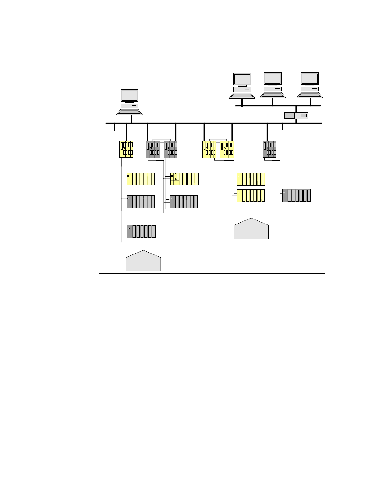
Use in Process Engineering
The figure below shows integration options for the S7 F/FH Systems in process
automation systems with PCS 7.
Fail-Safe Systems
1-2 A5E00085588-03
Page 19
Product Overview
Operator Stations (OS)
Central engineering system (ES)
PC
S7 F Sys
F-SMs
Standard SMs
ET 200M ET 200M
Standard SMs
ET 200S
Standard SMs
PC
PC
...
Standard Ethernet
Industrial Ethernet or PROFIBUS
S7-400H S7 FH Sys S7-400 Standard
F-SMs
F-SMs
ET 200M ET 200M
Boiler prot.
Emerg. stop
PC
Burner,
coal mill
Fail-Safe Systems
A5E00085588-03
1-3
Page 20
Product Overview
7 F System
safe signal modules
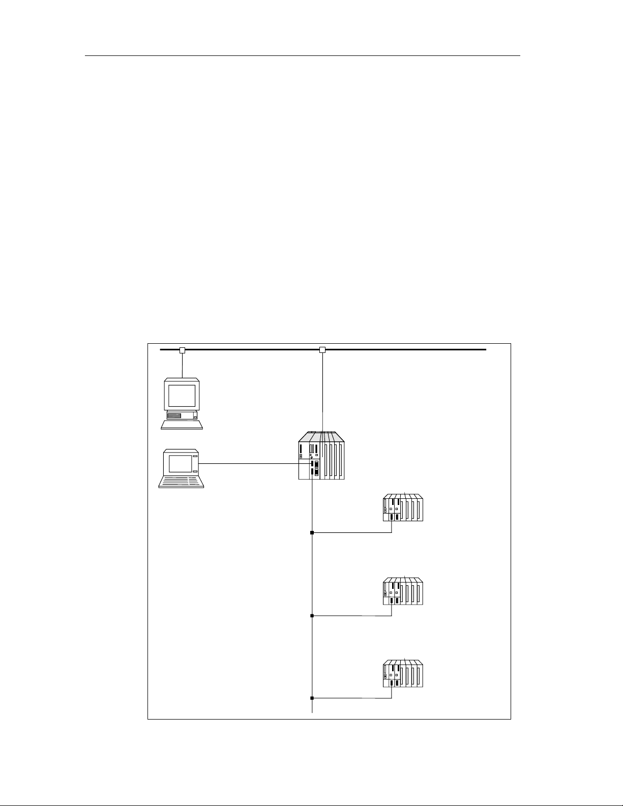
1.2 Basic Configuration Variants
This section describes the two basic configuration variants of F-Systems:
• Fail-safe S7 F System
• Fail-safe, fault-tolerant S7 FH System
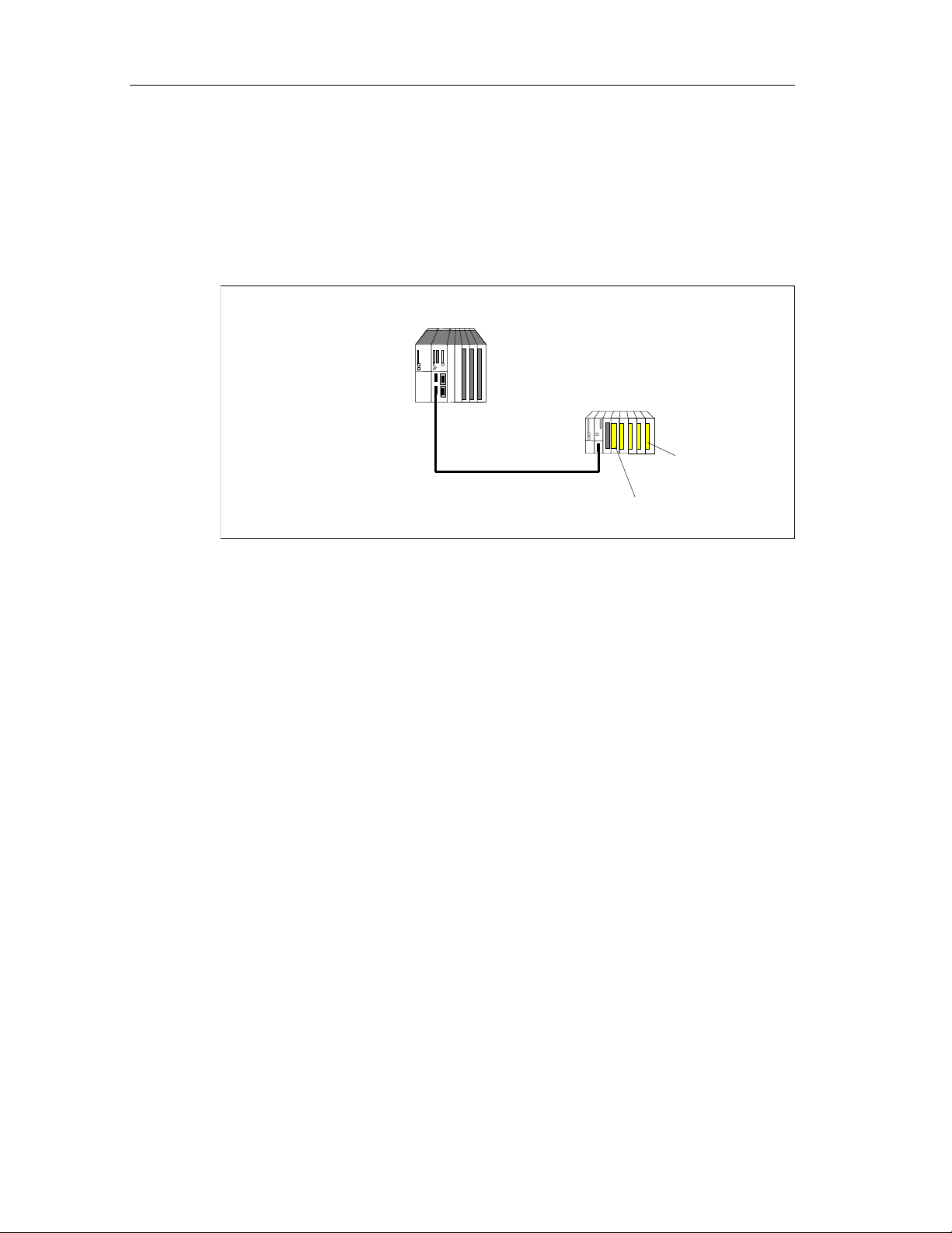
S7 F System
The S7 F System is a fail-safe automation system consisting of at least the
following components:
• An F-capable CPU module such as CPU 417-4 H that can run a fail-safe (F)
user program
• One or more fail-safe inputs/outputs (F-I/Os) in a distributed I/O device
(redundancy optional)
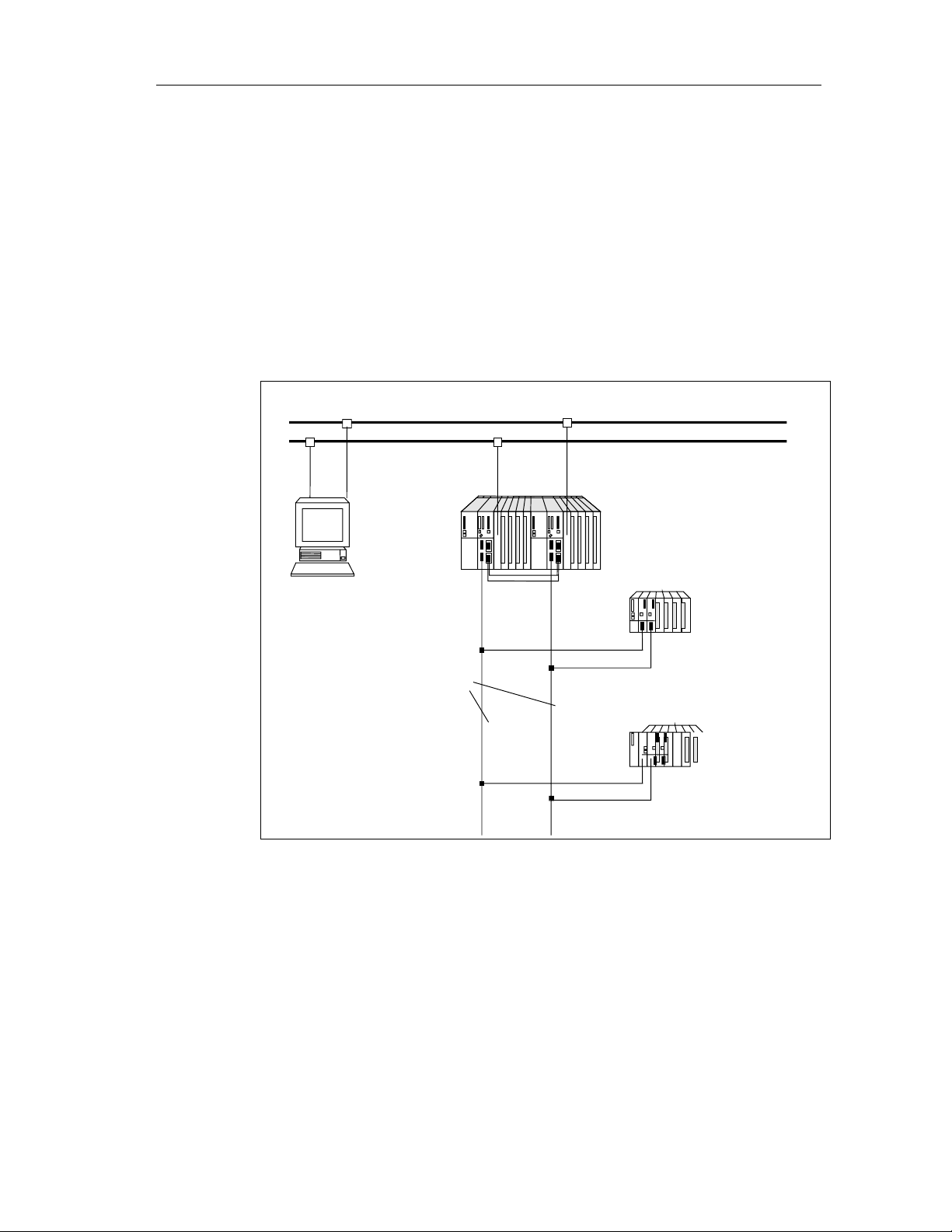
The following figure shows the hardware and software components of an F
System.
modules.
You can expand the configuration with standard S7-400 and S7-300
Operator Station
(system visualization)
Programming device
Programmable controller
S
ET 200M distributed I/O device
Fail-
(optionally redundant)
ET 200M distributed I/O device
Standard modules
(optionally redundant)
ET 200S distributed I/O device
Standard modules
Fail-Safe Systems
1-4 A5E00085588-03
Page 21
Product Overview
S7 FH System
The S7 FH System is a fail-safe, fault-tolerant automation system consisting of at
least the following components:
• A fault-tolerant S7 400H system (master and standby) running a fail-safe (F)
• One or more fail-safe inputs/outputs (F-I/Os) in a distributed I/O device
The following figure shows an example of an S7 FH configuration with a redundant
CPU, shared, switched distributed I/O modules connected via a redundant system
bus.
user program
(redundancy optional)
Redundant system bus (PROFIBUS or Ethernet)
Operator station
(System visualization)
Redundant
PROFIBUS - DP
Programmable controller
S7 FH System
ET 200M distributed I/O device
Fail - safe signal modules
(optionally redundant)
ET 200M distributed I/O device
Standard modules
(optionally redun dant)
Fail-Safe Systems
A5E00085588-03
1-5
Page 22

Product Overview
Combination of Standard, Fault-Tolerant and Fail-Safe Components
Standard, fault-tolerant (H) and fail-safe (F) components and systems can be used
together as follows:
• Standard systems, H systems, F Systems and FH Systems can be used
together in a single system.
• Standard modules and F-I/Os can be used together in a single automation
system.
• A safety-related F user program can be run together with a non-safety-related
standard user program in a fail-safe (F) or fail-safe, fault-tolerant (FH) system.
The fact that fail-safe (F), fault-tolerant (H) and standard components can be
combined has the following advantages:
• You can set up a fully integrated automation system in which you can make
use of the innovation of the standard CPUs and, at the same time, use fail-safe
components independently of standard components such as FMs or CPs. You
can configure and program the whole system using standard tools such as
HWCONFIG and CFC.
• The fact that you can combine standard and fail-safe program parts in a single
CPU reduces acceptance costs because only fail-safe program parts are
subject to acceptance procedures. Maintenance costs can also be reduced by
locating as many functions as possible in the standard section, which can be
modified during operation.
Fail-Safe Systems
1-6 A5E00085588-03
Page 23
Product Overview
1.3 Components of an S7 F System
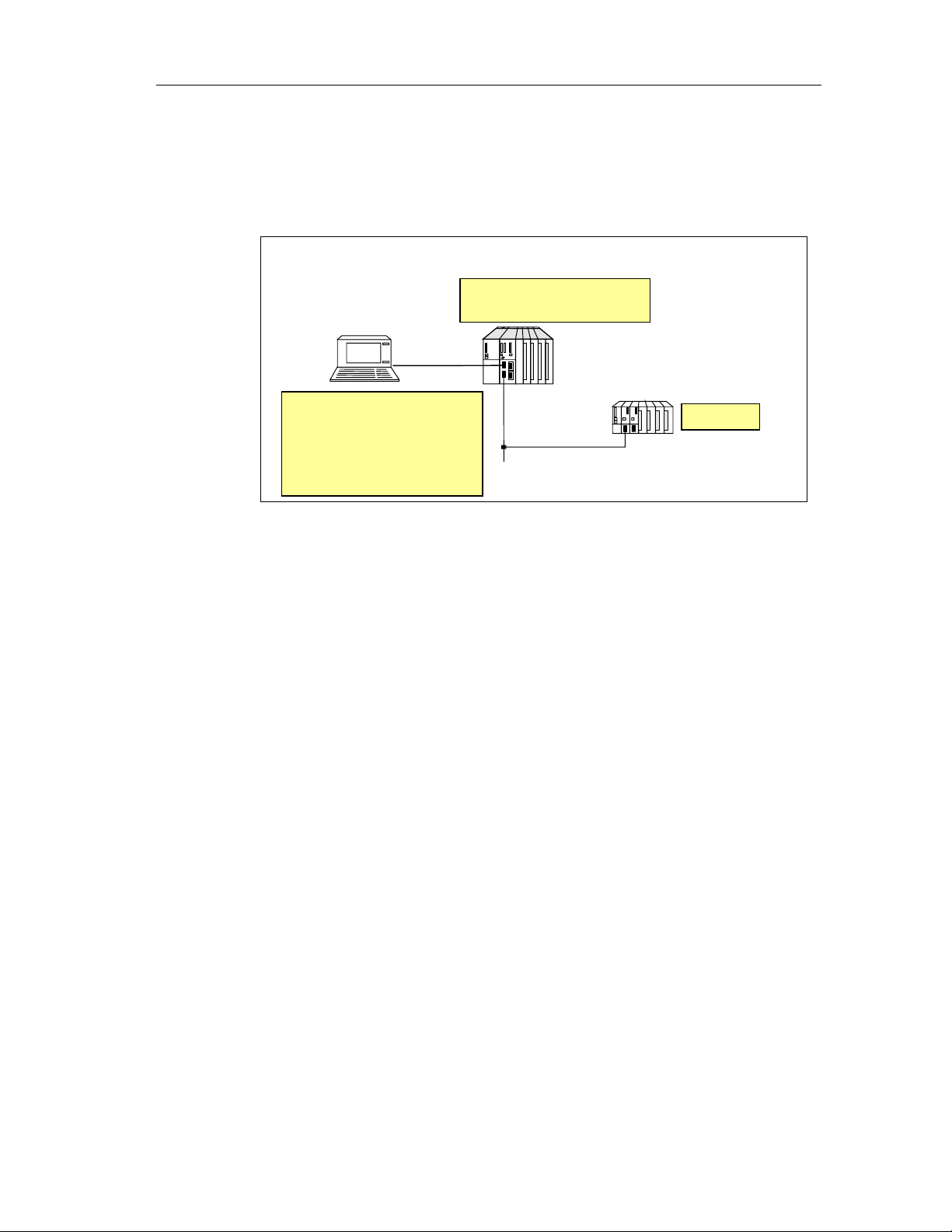
The figure below shows the hardware and software components required for the
configuration and operation of the S7 F.
S7 F programmable controller
F user program
Programming device
Optional package
S7 F Systems with
•
Configuration tool
•
F library
•
Safety program
editing
F run - time license
distributed I/O device
(optionally redundant)
F - I /Os
Interaction of the Components
The S7 F System consists of hardware and software components that have to be
combined with one another in order to configure an S7 F System.
Wiring the F-I/Os
The F-I/Os must be wired with the sensors and actuators in such a way as to
ensure that the desired safety level can be achieved.
Configuring the Hardware
The configuration set using HWCONFIG must correspond to the hardware
configuration; in other words, the circuit diagram of the I/O system must be
reflected in the parameter settings. The F-capable CPU must be configured.
Creating the F User Program
You create the fail-safe user program in CFC using fail-safe blocks from the
"Failsafe Blocks" library. For the connection to the F-I/Os you use F Channel and
Module driver blocks, to which you have to assign parameters. Some of the
parameters are assigned automatically as a result of the hardware configuration of
the F-I/Os.
When the executable F user program is generated, safety tests are carried out
automatically and additional fault detection functions incorporated.
Fail-Safe Systems
A5E00085588-03
1-7
Page 24

Product Overview
Compatibility of standard and fail-safe components in a programmable logic
controller
If you use a safety protector in the ET 200M, then you can operate fail-safe signal
modules with the S7-300 standard signal modules in an ET 200M even in safety
mode in SIL 3.
The safety protector protects the fail-safe signal modules from possible overvoltage
in the event of a fault. To do this, the fail-safe signal modules must be inserted in
the ET 200M configuration to the right of the safety protector, and all the standard
signal modules must be inserted to the left of the safety protector.
1.4 Hardware Components
An F System consists of hardware components that fulfill certain safety
requirements, such as:
• A CPU such as the CPU 417-4H with an F-Copy License
• F-I/Os
You can also expand the F System with standard components.
F-Capable CPUs
For S7 F/FH Systems, the CPU (e.g. the CPU 417-4 H as of V2.0) with an F-Copy
License is used either individually or as a fault-tolerant master/standby system.
The F-Copy License permits you to use the CPU as an F-CPU (i.e. to run a failsafe user program on it).
An F-capable CPU is a CPU that is approved for use in the S7 F/FH. It only
becomes an F-CPU if there is an F user program running on it. Otherwise, a
standard S7 program runs on the CPU. A combination of standard and F user
programs is possible because the safety-related data of the F user program is
protected from the influence of non-safety-related data. The CPU must be
configured as an F-CPU in this case as well.
Safety-relevant sections of the user program must be password-protected on the
CPU and in the ES/programming device against unauthorized access. In addition,
comprehensive self-tests run on the CPU. These ensure a high rate of fault
detection.
F-I/Os
The following F-I/Os are available:
For ET 200M:
• SM 326; DI 24 x 24 V DC; with Diagnostic Interrupt
• SM 326; DI 8 x NAMUR; with Diagnostic Interrupt
• SM 326; DO 10 x 24 V DC/2A, with Diagnostic Interrupt
• SM 336; AI 6 x 13Bit, with Diagnostic Interrupt
Fail-Safe Systems
1-8 A5E00085588-03
Page 25

Product Overview
ET 200M F-I/Os can be used in a single-channel or redundant configuration:
Please refer to the manual: Automation System S7-300 Fail-Safe Signal Modules’
For ET 200S:
• PM-E F 24 VDC PROFIsafe Power Module
• 4/8 F-DI 24 VDC PROFIsafe Digital Electronic Mod ul e
• 4 F-DO 24 VDC/2 A PROFIsafe Digital Electronic Module
• PM-D F PROFIsafe Power Module
Please refer to the manual: ET 200S Distributed I/O System, Fail-Safe Modules
Standard Components
The restrictions for fault-tolerant systems apply to the use of standard components.
You will find the restrictions for standard components in safety mode of fail-safe
signal modules in the safety information in Chapter 3 of the "S7-300 Programmable
Controller, Fail-Safe Signal Modules".
Additional Information
You can find detailed descriptions of the hardware components for the S7 F/FH
Systems in the following manuals:
• S7-400, M7-400 Programmab le Con tr ol lers , Insta llati on and Modu le Data
• S7-400H Programmable Controller, Fault-Tolerant Systems
• S7-300 Programmable Controller, Fail-Safe Signal Modules
• ET 200S Distributed I/O System, Fail-Safe Modules
Fail-Safe Systems
A5E00085588-03
1-9
Page 26

Product Overview
1.5 Software Components
The S7 F Systems have the following software components:
• S7 F Systems (Programming)
• S7 F Configuration Pack (Configuration of the F-I/O’s)
• The fail-safe user program (F user program) on the CPU
The S7 F Systems Optional Package
The S7 F Systems optional package is available for the configuration and
programming of the S7 F System. This gives you:
• Support for the configuration of the F-I/Os with HWCONFIG.
• The "Failsafe Blocks" library for the programming of fail-safe user programs.
• Support for the processing of the F user program and for the integration of fault
detection functions in the F user program.
Fail-Safe User Program
A fail-safe user program is referred to below simply as a Safety Program.
You create Safety Programs with CFC using the fail-safe blocks contained in a
library shipped with the S7 F Systems optional package. The fail-safe blocks
contain fault detection and fault reaction functions, as well as functions for
programming safety functions. In other words, they ensure that failures and faults
are detected and that an appropriate reaction is initiated that will keep the Fsystem in a safe state or return it to a safe state.
The user program on the CPU can be made up of safety-related sections (Safety
Program) and not safety-related sections (Standard Program). The Safety Program
is written in separate CFC charts. A combination of F and standard blocks in one
chart is not permissible and is detected during compilation. Data transfers between
the standard and the Safety Program are carried out via conversion blocks.
During compilation, certain fault detection and fault reaction functions are
automatically added to the Safety Program. The S7 F Systems optional package
also provides functions for comparing Safety Programs and supporting the
acceptance of Safety Program s .
Additional Information
You can find detailed information in the following sections.
• Configuration
• Programming
• Fail-Safe Blocks
and in the context-sensitive help information.
Fail-Safe Systems
1-10 A5E00085588-03
Page 27

Product Overview
1.6 Installing the S7 F Systems Optional Package
Before using an existing project with S7 F Systems V5.2, please read this entire
section which provides you with:
• getting started information applicable to the three use-case-scenarios
described below.
• the three use-case-scenarios are as follows, please select the one that best
suits your needs:
1. Compiling/editing current projects based on Failsafe Blocks (V1_1)
a. Upgrading a PC/Programming Device/Workstation containing S7 F
Systems V5.1 Optional Package
b. Installing S7 F Systems V5.2 Optional Package on a new
PC/Programming Device/Workstation
2. Upgrading current projects based on Failsafe Blocks (V1_1) to Failsafe Blocks
(V1_2)
3. Modifying or creating projects based on Failsafe Blocks (V1_2)
1.6.1 Getting Started Information Applicable to All Use-Case-Scenarios
Installing the Optional Package
1. Start the PC/Programming Device/Workstation that has the STEP 7 basic
software package installed. Make sure that there are no open STEP 7
applications.
2. Insert the optional package product CD.
3. Run the SETUP.EXE program on the CD.
4. Follow the setup program instructions.
Reading the Readme File
The readme file (S7 F Systems – Readme) contains important, up-to-date
information about the software. You can display this file on completion of the setup
program, or open it later using the Start > Simatic > Product Notes > English
menu command. It is located in the S7ftl directory of STEP 7.
Starting the Optional Package
The optional package does not contain any applications that have to be started
explicitly. Support for configuration and programming of the F-Systems is
integrated in SIMATIC Manager, HWCONFIG and CFC.
Fail-Safe Systems
A5E00085588-03
1-11
Page 28

Product Overview
Displaying the Integrated Help System
Context-sensitive help information is available for the optional package dialog
boxes. Help can be displayed at any time during configuration or programming by
pressing F1, or clicking the Help button. You can obtain more help information by
choosing the Help > Contents > Calling Help on Optional Packages > S7-
400F/FH – Working with F Systems.
Authorization
Authorization is required for the S7 F Systems optional package. Authorization can
be installed in the same way as STEP 7 and the optional packages. You can find
information on how to install and work with the authorization component in the
readme file and in STEP 7’s main help system.
Note
SIMATIC S7 F Systems V5.0 lic en se al so su pports V5.2
F-Copy License
An F-Copy License permits you to use the CPU as an F-CPU (e.g. to run a Safety
Program on it).
1.6.2 Use-case-scenarios
Scenario 1: Compiling/Editing Current Projects based on Failsafe Blocks (V1_1)
1. a. Upgrading From S7 F-Systems V5.1 to S7 F-Systems V5.2 to Support
Failsafe Blocks (V1_1) Projects
Use this scenario if you have:
An existing PC/Programming Device/Workstation with S7 F Systems V5.1 Optional
Package installed, and you wish to use existing projects based on Failsafe Blocks
(V1_1).
Fail-Safe Systems
1-12 A5E00085588-03
Page 29

Product Overview
Software Requirements
The following software packages must be installed on the PC/programming device
in order to use, modify, or create projects based on Failsafe Blocks (V1_1) library
with S7 F Systems V5.2:
• S7 F Systems V5.2
• STEP 7 V5.1.3 or higher
• CFC V5.2.4
• S7 H Systems Optional Package V5.1or higher (required for S7 FH Systems)
Procedure
If S7 F Systems V5.1 is already installed, the projects based on Failsafe Blocks
(V1_1) library are supported without an y addit ional pr oc ed ures .
1.b. Installing S7 F Systems V5.2 on a New PC to Support Failsafe Blocks (V1_1)
Projects
Use this scenario if you have:
Purchased a new PC/Programming Device/Workstation, and you wish to use
projects based on Failsafe Blocks (V1_1) library.
Software Requirements
The following software packages must be installed on the PC/programming device
in order to use, modify, or create projects based on Failsafe Blocks (V1_1) library
with S7 F Systems V5.2:
• S7 F Systems V5.2
• STEP 7 V5.1.3 or higher
• CFC V5.2.4
• S7 H Systems Optional Package V5.1or higher (required for S7 FH Systems)
Procedure
1. If S7 F Systems V5.2 is installed, uninstall it.
2. Install S7 F Systems V5.1
3. Install S7 F Systems V5.2
4. If you had PCS7 Driver Blocks or PCS7 Library installed, you must also install
Fail-Safe Systems
A5E00085588-03
these.
1-13
Page 30

Product Overview
Scenario 2: Upgrading Failsafe Blocks (V1_1) Projects to Failsafe Blocks (V1_2)
Use this scenario if you wish to:
Upgrade current projects based on Failsafe Blocks (V1_1) to the new Failsafe
Blocks (V1_2) library contained in S7 F Systems V5.2. You must have the
minimum software requirements to allow this.
Software/Firmware Requirements
The following software packages must be installed on the PC/Programming
Device/Workstation in order to upgrade projects based on Failsafe Blocks (V1_1)
library to Failsafe Blocks (V1_2):
• S7 F Systems V5.2
• STEP7 V5.2 or higher
• S7 H Systems Optional Package V5.1 or higher (required for S7 FH Systems)
• CFC V5.2.4
• CPU S7-417F/FH V3.1 or higher
ET 200S fail-safe module drivers are available, but this requires CFC V6.0.
Fail-Safe Systems
1-14 A5E00085588-03
Page 31
Product Overview
Procedure: Updating Failsafe Blocks (V1_1) Project to Failsafe Blocks (V1_2)
1. Ensure the above software requirements are met.
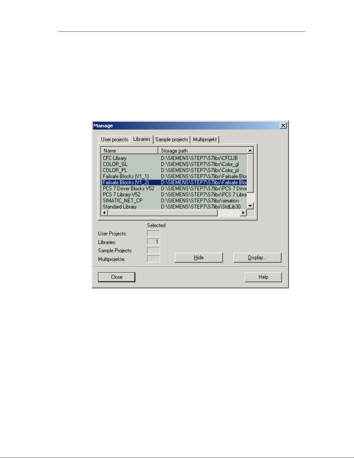
2. Ensure Failsafe Blocks (V1_2) is available within the Manage dialog box in
SIMATIC Manager.
a. Within SIMATIC Manager open the Manage dialog box by choosing File
>Manage…
b. Verify Failsafe Blocks (V1_2) is in the list. If it is, then go to step 3.
Fail-Safe Systems
A5E00085588-03
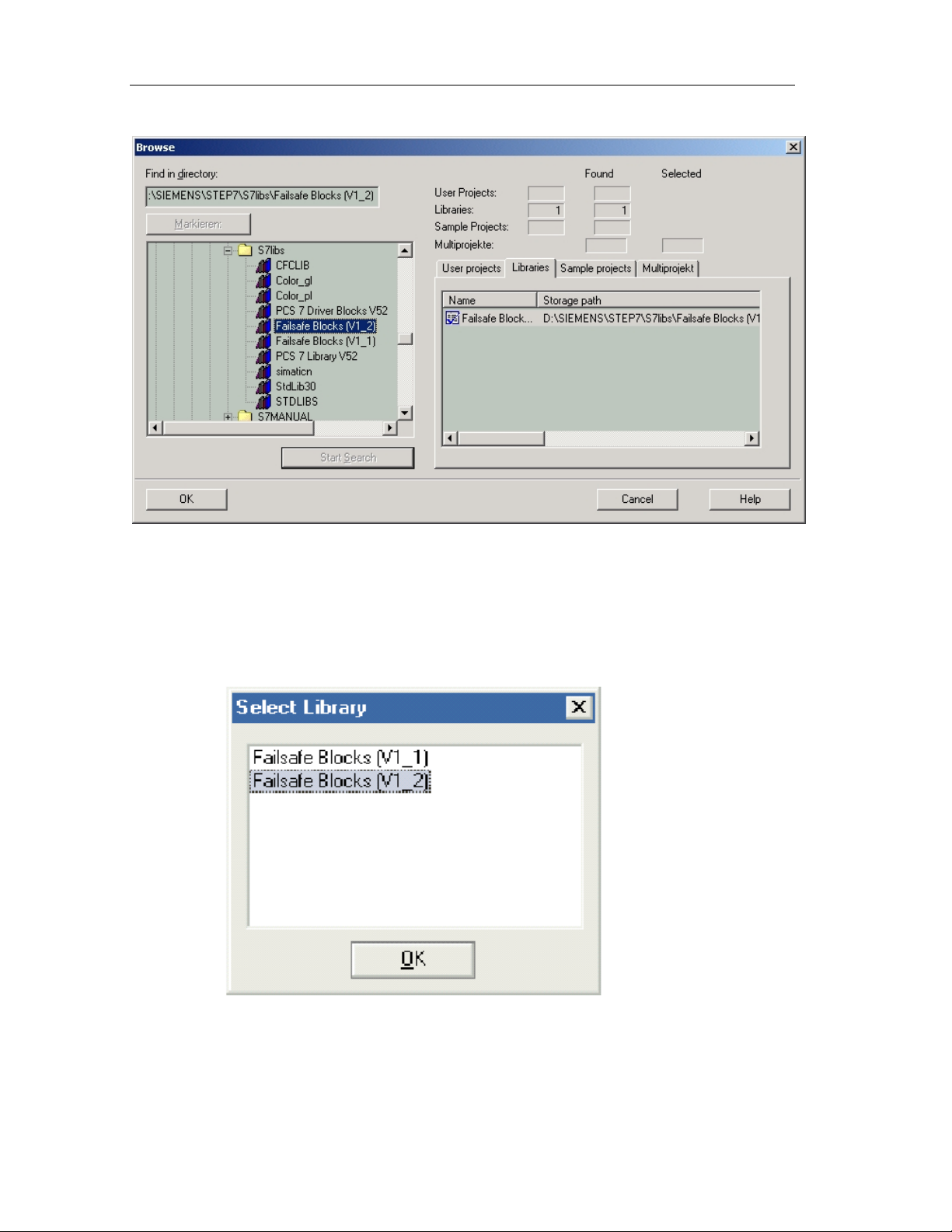
c. Open the library within SIMATIC Manager by choosing File > Open… and
press the Browse button.
d. Open the folder \SIEMENS\STEP7\S7LIBS and select Failsafe Blocks
(V1_2) and press OK. This will open the Failsafe Blocks (V1_2) library.
1-15
Page 32
Product Overview
e. Close the library.
f. Go back to step 2.a.
3. Choose the Options > Edit Safety Program menu command.
4. Press the Library Version... Button.
5. Select the Library to which you wish to upgrade to, and press the OK button.
6. Open a CFC Chart from the Program.
7. Choose the Options > Block Types menu command.
8. Select all blocks in the Charts Folder pane.
Fail-Safe Systems
1-16 A5E00085588-03
Page 33

Product Overview
9. Press the New Versio n... But ton to import.
10. Recompile the program.
Important Note
You must Import the new Block Type after upgrading the library to insure all blocks
are up to date. Failure to Import new block types may result in a failed compile.
Important Note
Unplaced F-Blocks from the block container are automatically deleted when the
safety program is compiled.
Important Note
Run-time groups containing F-Blocks in task OB1 must be moved to OB3x
because OB1 is no longer supported.
Fail-Safe Systems
A5E00085588-03
1-17
Page 34

Product Overview
Scenario 3: Modifying or Creating Projects Based on Failsafe Blocks (V1_2)
Use this scenario if you wish to:
Modify or create projects based on Failsafe Blocks (V1_2) library contained in S7 F
Systems V5.2. You must have the minimum software requirements to allow this.
Software/Firmware Requirements
The following software packages must be installed on the PC/Programming
Device/Workstation in order to modify or create projects based on Failsafe Blocks
(V1_2) library:
• S7 F Systems V5.2
• STEP7 V5.2 or higher
• S7 H Systems Optional Package V5.1 or higher (required for S7 FH Systems)
• CFC V5.2.4
• CPU S7-417F/FH V3.1 or higher
ET 200S fail-safe module drivers are available, but this requires CFC V6.0.
Procedure
There are no additional procedures beyond this.
Fail-Safe Systems
1-18 A5E00085588-03
Page 35

Product Overview
1.7 Working with F-Systems
This section describes the basic procedure for working with fail-safe systems. Only
those steps that are relevant to F-Systems and differ from the standard procedure
are included.
Planning the System
Process-dependent planning tasks such as defining a piping and instrumentation
diagram, creating a flowchart, creating a measuring point list, defining a structure,
etc. are not described here. When you plan the system, specify the required safety
functions with the corresponding Safety Integrity Levels (SILs). From these, derive
the demands on the components in order to implement the safety functions (PLCs,
sensors, actuators). These decisions affect other tasks such as hardware
installation, configuration, and programming.
!
Safety Note – Keep Safety and Standard Functions Separate
It is important to separate standard (e.g. not safety-related) and safety (e.g. safetyrelated) functions rigorously during planning.
Fail-Safe Systems
A5E00085588-03
1-19
Page 36

Product Overview
Basic Procedure
Configure S7 F/FH hardware
Set addresses on the F-I/Os via DIP switches
Wire modules according to required circuit program
Configure system
Parameterize CPU for safety program
Parameterize F-I/Os according to safety class and circuit diagram
Create Safety Program
Place, interconnect, and parameterize F function blocks
Generate executable code and load to the CPU of the S7 F/FH
Commission the system
Have safety-related sections accepted by expert before safety mode
is operational
Maintain system
Replace hardware components
Change Safety Program
Update operating system
Fail-Safe Systems
1-20 A5E00085588-03
Page 37

Product Overview
Compiling as a Program
To compile the Safety Program, proceed as follows:
1. Carry out a consistency check by choosing the Chart > Check Consistency
>Charts as Program menu command. (This step is optional.)
2. Choose the Chart > Compile > Charts as Program menu command.
3. Select one of the following options in the "Compile Charts as Program" dialog
box:
• Entire Program, if the whole program is to be compiled.
• Changes, if only the changes are to be compiled.
4. If the F module drivers are not yet placed, select the "Generate Module
Drivers" check box in the "Compile Charts as Program" dialog box. This
automatically inserts and interconnects the required F module drivers in
separate charts @Fx.
Result: The Safety Program is compiled and can be downloaded to the CPU.
Safety functions are added to the charts of the Safety Program automatically. The
automatically added elements, such as additional blocks and interconnections, are
partially visible in the CFC charts, but must on no account be changed or deleted.
Graphical moving of blocks within the same chart is permissible
Fail-Safe Systems
A5E00085588-03
1-21
Page 38

Product Overview
Fail-Safe Systems
1-22 A5E00085588-03
Page 39

2 Getting Started
2.1 Introduction
This introduction uses concrete examples to walk you through the steps required to
create a working application, which will enable you to discover how a fail-safe
automation system works, and how it behaves in the event of a fault/error.
The following two systems will be used as examples to lead you through the initial
commissioning phase to an actual work ing appl ication.
• A fail-safe, S7 F system, and
• A fail-s afe, fault-tolerant S7 FH system
Terminology
The following table describes terminology used in the example projects.
F_SHUTDN A standard function block used to manage the shutdown and
restart of the Safety Program. Please se e cha pter 8 for more
information on the F_SHUTDN function block.
F-run-time
group
Safety
Program
Force Full
Shutdown
Full
Shutdown
Partial
Shutdown
This is a run-time group that has F-Blocks within it. The Step 7
definition of run-time groups: (Run-time groups are used to
structure tasks. The blocks are installed sequentially in the runtime groups. Run-time groups can be activated and deactivated
separately. If a run-time group is deactivated, the blocks it
contains will no longer be activated.)
This is the collection of all F-run-time groups within the project.
The user may force the manual shutdown of the entire Safety
Program through the RQ_FULL input of the F_SHUTDN function
block.
The Shutdown logic responds to an internal diagnostic that has
detected a failure by disabling the entire Safety Program (Please
note that CPU will remaining running). This is configured on the
F_SHUTDN SHUTDOWN input.
The Shutdown logic responds to an internal diagnostic that has
detected a failure by disabling only that F-run-time group that
encountered the failure (Please note that CPU will remain
running). This is configured on the F_SHUTDN SHUTDOWN
input.
Fail-Safe Systems
A5E00085588-03
2-1
Page 40

Getting Started
Restart The shutdown logic’s F_SHUTDN RE START in put al low s you to
restart the Safety Program that has been shutdown.
Reintegration of I/O may be necessary after this action.
Shutdown The Shutdown logic responds to an internal diagnostic that has
detected a failure by disabling either the entire Safety Program
(Full Shutdown) or the isolated F-run-time group (Partial
Shutdown). The shutdown logic response depends on how you
configured the shutdown logic, either Partial Shutdown or Full
Shutdown.
S7 F Systems V5.2 Shutdown Logic
S7 F Systems V5.2 is packaged with an enhancement that allows you to manage
shutdown and restart of the Safety Program. When an F-run-time group is created
by the user, and the project is compiled, the shutdown logic is automatically placed
by the CFC Editor. The CFC Editor creates charts to contain this logic:
@F_ShutDn and @F_DbInit1. Please note that the @ is used by the CFC editor to
denote automatically created and is a reserved name. There are other charts that
are automatically placed that are used to provide information to the shutdown logic
and these include: @F_Init1, @F_CycCo-OB35, and @F_TestMode.
At the center of the shutdown logic is the F_SHUTDN function block in the
@F_ShutDn chart. The F_SHUTDN block provides you with the following action:
• You can force a manual shutdown of the entire Safety Program or you can
restart the shutdown Safety Program.
• You can use the SHUTDOWN input to set either Full Shutdown or Partial
Shutdown.
• You can use the FAILURE input of the F_SHUTDN function block to identify
that a failure occurs and observe the FULL_SD output if a failure is detected
while SHUTDOWN = Full Shutdown.
The F_SHUTDN block also has an input F_PRG_SI to provide you with the overall
Safety Program Signatur e, and an output SAF E_ M to provid e you with the current
safety mode status of the Safety Program.
The F_SHUTDN function block also reports error events to the Diagnostic Buffer.
The events reported are Restart, Full Shutdown, and Partial Shutdown. Similarly,
alarm messages are also reported to WinCC under these three conditions.
Basic Procedure
Carry out the following tasks step by step:
• Set up the hardware (F-I/O and CPU).
• Configure the F-system.
• Create a fail-safe program using CFC charts.
• Commission the F-system, and check if the fail-safe program is operational.
Fail-Safe Systems
2-2 A5E00085588-03
Page 41

Getting Started
You will then be able to configure a fault-tolerant F-system.
Sample Projects Provided
Note
The sample projects require Step 7 V5.2 and the S7 H Systems Optional Package
Version 5.1.
You can find two sample projects in step7\Examples:
• ZEN32 01_FSystem_Fproj – For an F System
• ZEN32 02_FHSystem_FHProj – For a fault-tolerant FH System
You can use the examples to check the results of similar project sessions
described below.
Passwords
The passwords for the projects provided are:
• CPU password: anna
• Safety Program password: otto
Fail-Safe Systems
A5E00085588-03
2-3
Page 42
Getting Started
ET 200M Distributed I/O
Safety Protector
2.2 S7 F System - Getting Started
2.2.1 S7 F System, Setting up the Hardware
The following figure shows you an example of a hardware configuration.
S7 F programmable
controller
Profibus DP Cable
Single-channel, one-sided
Fail-safe
signal modules
Module
For this example, you need the following hardware components:
• A programmable logic controller consisting of:
- 1 mounting rack (UR2-H)
- 1 power supply (PS 407 10A)
- 1 CPU 417-4H
• An ET 200M distributed I/O device with an active backplane bus consisting of:
- 1 power supply (PS307 5A)
- 1 IM 153-2 Bus Interface Module
- 1 Safety Protector Module
- 1 fail-safe digital input module (SM 326F DI 24xDC24V)
- 1 fail-safe digital output module (SM 326F DO10xDC24V/2A)
• Other accessories
- PROFIBUS cables and connectors
Set the DIL switches for the individual components as follows:
• IM153-2 PROFIBUS address 3
• SM 326F DI 24 Module address 8
(Only found on the reverse side; only in steps of 8)
2-4 A5E00085588-03
• SM 326F DO10 Module address 24
(Only found on the reverse side; only in steps of 8)
Fail-Safe Systems
Page 43

Getting Started
Connect actuators, or alternatively terminating resistors, to the output module (e.g.
between 12 Ω and 3.4 kΩ with 1 watt), or disable group diagnosis for unused
channels in the hardware configuration.
Interface restrictions between S7-400 CPU and ET 200M I/O
The ET 200M components which can be used in safety mode depend on the safety
class and the use of a safety protector in the ET 200M configuration:
• If you comply with the requirements of safety class SIL 2 or use a safety
protector in SIL 3 in ET 200M, you can use all the available IM 153-2 interface
modules and you can set up the PROFIBUS-DP with the copper cable (as in
standard mode).
• If you don’t use a safety protector in SIL 3 in ET 200M, you must connect the
PROFIBUS-DP lines - the S7 F System and the S7 400H programmable
controllers with fiber optic cables as described in the S7 F/FH Programmable
Controllers.
Additional Information
You can find detailed descriptions of the hardware components in the following
manuals:
•
S7-400, M7-400 Programmab le Controllers, Installation and Module
Specifications
•
S7-400H Programmable Controller, Fault-Tolerant Systems
•
S7-300 Programmable Controller, Fail-Safe Signal Modules
•
ET 200S Distributed I/O System, Fail-Safe Modules
Fail-Safe Systems
A5E00085588-03
2-5
Page 44

Getting Started
2.2.2 Configuring the S7 F System
The following steps show you how to create a new project and configure the
hardware setup described above.
Procedure
1. Open SIMATIC Manager, and create a new project called "FProject" using the
File > New menu command.
2. Insert a new S7-400 station: Ins ert > Statio n > SIMATIC 400 Station.
3. Open the hardware configuration (HWCONFIG) of the SIMATIC 400(1) station
created (you can change the name) by double-clicking the hardware object (or
right-click the Open Object pop-up menu command).
4. Insert the individual hardware components of the SIMATIC 400 from the
"Hardware Catalog" window (you can open the catalog with View > Catalog)
by dragging and dropping them to the station window.
5. First place the UR2 mounting rack from the RACK 400 catalog.
6. Insert the standard power supply (PS 407 10 A) in slot 1 of the mounting rack.
7. Place the CPU 417-4H V3.1 in slot 3: Create a subnet (which will subsequently
be connected to the ET 200M) in the "Properties - PROFIBUS Interface DP
Master" dialog box by clicking New.
Fail-Safe Systems
2-6 A5E00085588-03
Page 45

Getting Started
8. Select the CPU, and choose the Edit > Object Properties menu command (or
9. From the PROFIBUS-DP catalog, insert the IM 153-2 directly in the
10. Insert the input module SM 326F DI24xDC24V from the DI-300 catalog of the
11. Select the module. Right-click to choose Edit Symbols from the pop-up menu
12. Double-click to open the properties dialog box, and select "Enable Diagnostic
13. Insert the output module SM 326F DO10xDC24V/2A from the DO-300 catalog
double-click the CPU): The "Properties - CPU 417-4H" dialog box appears:
Enter a password for the CPU on the "Protection" tab, and select the
"CPU Contains Safety Program" check box.
"PROFIBUS(1): DP Master System (1)" in the station window: Enter the
address 3 on the "Parameters" tab in the "Properties - Profibus Interface ET
200M IM153-2" dialog box.
IM 153-2 in slot 4 of the ET 200M (you can see a detailed view in the lower
part of the station window).
and enter symbolic names for all the channels: You will need the symbolic
names for the channels to create the user program.
Interrupt" and "Safety Mode" with "1oo1 Evaluation" on the "Inputs" tab.
of the IM 153-2 in slot 5 of the ET 200M.
14. Assign symbolic names to all the channels (e.g. by using "Add to Symbol").
15. Open the properties dialog box, select "Safety Mode in Accordance with SIL2 /
AK4" on the "Outputs" tab.
This completes hardware configuration.
16. Save the current configuration by choosing the Station > Save and Compile
menu command: The system blocks are generated and stored in the program
container.
17. Download the hardware configuration to the CPU by means of the PLC >
Download to Module menu command.
Fail-Safe Systems
A5E00085588-03
2-7
Page 46

Getting Started
2.2.3 S7 F System, Creating a Fail-Safe User Program
In the following steps you create a fail-safe CFC user program that interconnects
the fail-safe inputs with the fail-safe outputs.
The Safety Program consists of several charts:
• At least one chart for user logic program interconnection (F-Blocks)
• System charts automatically created for diagnostics:
• Charts for the Safety Critical Diagnostic blocks
• Charts for the Safety Program Shutdown and Restart Logic
Creating CFC Charts
1. Open SIMATIC Manager , and open the 400 Sta tio n in your proj ect.
2. Expand the selections S7 Program to display Source, Blocks and Charts. If the
Charts folder does not exist, create one by right clicking on S7 Program and
select "Insert New Object, Chart Folder“.
3. Right click on the Charts folder.
4. Choose a new Chart, and call it "F Blocks".
Creating the Run Sequence
The F function blocks must be inserted in run-time groups. Function Blocks have
not been placed yet. However, you can setup a run-time group to be the default
destination for new F-Blocks.
1. Within your project in SIMATIC Manager, click on the Charts folder.
2. Open the F-Blocks chart by double-clicking on it.
3. Open the Run Sequence either by pressing Control-F11 or selecting Edit>Run
Sequence within the CFC Editor.
4. Select the OB3x that you wish to contain the F-Blocks (OB35 is the most
common) by clicking on the OB3x, in this example, OB35.
5. If the run-time group has not already been added, insert a run-time group by
right clicking on the OB35 and selecting "Insert Run-Time Group…". The
Insert Run-Time Group dialog box will appear.
6. Enter the name of the Run-Time group, in this case call it "F Blocks". Enter a
comment if you desire. Do not change the Scan rate or Phase Offset. Press
OK.
7. Select the run-time group and right-click.
8. Select Predecessor for Installation from the pop-up menu or press F11. By
selecting this option, all newly created F-Blocks will automatically be placed
into this F-run-time group.
Fail-Safe Systems
2-8 A5E00085588-03
Page 47

Getting Started
Inserting F-Blocks
1. Close the Run Sequences either by closing the window within CFC editor, or
pressing Control-F11.
2. Insert user logic such as F_ADD_R, F_LIM_R etc… Refer to section Inserting
and Interconnecting Fail-Safe Blocks for details.
Note 1
The fail-safe blocks of the Failsafe Blocks library are yellow to differentiate them
from standard blocks.
Note 2
Previously a chart needed to be added manually by the user with the F_CYC_CO.
This is no longer necessary or allowed. The Placement of the F_CYC_CO blocks
is now a system function.
3. Insert two F_CH_DI F channel drivers to read in the fail-safe input module,
channels 0 and 1 (input value is at the Q output of the F_CH_DI FB).
4. Interconnect the VALUE input with the symbolic names for channel 0 (e.g.
E24.0) and channel 1 (e.g. E24.1) using the right mouse button and
Interconnection to Address.
5. Assign a value of 1 to the ACK_NEC input: in the event of an error, user
acknowledgment (at ACK_REI) is required for reintegration.
6. Place two F_CH_DO F channel drivers (values are at the I input) to write to the
fail-safe output module.
7. Interconnect the VALUE output with the symbolic name for channel 0 (e.g.
A.8.0) and channel 1 (e.g. A.8.1).
8. Assign the value 1 to the ACK_NEC input.
9. Connect the Q outputs of the two F_CH_DI with the I inputs of the
corresponding F_CH_DOs.
10. Insert the F_QUITES block (fail-safe acknowledgment) from the library and
connect the OUT output to the ACK_REI inputs of the two F_CH_DI and the
two F_CH_DOs.
Fail-Safe Systems
A5E00085588-03
2-9
Page 48

Getting Started
11. Check again in the run-time group overview whether all the F-blocks are in the
F-blocks run-time groups as required.
Compilation of the Blocks
Choose the Chart > Compile > Charts as Program menu command to compile
your program. Activate the Generate Module Drivers option.
You will be prompted to enter a password for the safety program (see above under
Passwords). This password will be requested on future compiles.
You will be prompted for MAX_CYC time for every OB3x with a failsafe program.
After the charts have been compiled, the following control blocks are integrated
automatically by the
• In the F-CycCo-Obxx chart F_CYC_CO, F_TEST, and F_TESTC (for tests)
• In chart @F_TestMode the F_TESTM for Test Mode management
• In chart @F_RtgDiagxx the F_PLK and F_PLK_O (for program execution
monitoring)
• In a separate chart @F1 F_M_DI24 and F_M_DO10 (F module driver)
• In a separate chart @F_ShutDn, the shutdown logic is created containing the
F_SHUTDN, RTG LOGIC, and standard logic blocks.
"S7 F Systems" option package:
Fail-Safe Systems
2-10 A5E00085588-03
Page 49

Getting Started
• In a separate chart @F_DbInit contains the DB_INIT function blocks required
for performing an F-run-time group coldstart.
• All the required error OBs have also been inserted in the block container in
SIMATIC Manager.
Note
The CFC charts with fail-safe blocks are yellow and marked with an "F" to
distinguish them from standard charts.
Downloading the Program to the CPU
Download the CFC charts to the CPU by means of the PLC > Download to
Module menu command.
2.2.4 Starting Up the S7 F System
Start the programmable controller by switching the mode selector to RUN-P and
carrying out a warm restart on the CPU (PLC > Operating Mode).
If you apply voltage to inputs 1 or 2, the corresponding output is set. Get the
voltage from the Vs terminal (Sensor Supply).
Fail-Safe Systems
A5E00085588-03
2-11
Page 50

Getting Started
2.2.5 S7 F System, Monitoring Errors
Removing the Front Connector
1. Remove the front connector of the SM 326F DI24xDC24V.
You have triggered an error at the SM 326F DI24xDC24V. The SF LED comes
on and the SAFE LED goes out. The EXTF LED of the CPU comes on, but the
CPU remains in RUN.
2. Go into the diagnostic buffer of the CPU (PLC > Module Information >
Diagnostic Buffer). The signal module with the address 8 is reported as
defective, but because OB82 is present, the diagnostic interrupt does not result
in CPU stop.
3. You can read out detailed information on defective modules by choosing PLC
> Hardware Diagnostics. Double-click DI 24 in the open ONLINE hardware
configuration, and look at the diagnostic buffer in the module state.
4. Go to the "F blocks" CFC chart, and switch to test mode. The QBAD output of
the F_CH_DI F channel driver blocks are set to TRUE: There is an error.
QUALITY=16#48 indicates that there are substitute values at Q output.
5. Now insert the front connector in the SM 326F DI24xDC24V again. After a
reintegration time of approx. 1 minute, the SAFE LED comes on again and the
SF LED goes out. The EXTF LED on the CPU goes out.
The module is reported as OK in the diagnostic buffer of the CPU.
In test mode you can still see that the driver block is reporting an error: If, for
example, you apply voltage at terminal 5 for input 8.0, the Q output of the
driver block remains at 0. The SM 326F DI24xDC24V must therefore be
reintegrated first: The ACK_REQ=1 output requests an acknowledgment at the
fail-safe ACK_REI input.
6. In our case, you can output a signal of 1 for one cycle via the F_QUITES F FB,
whose input can be connected to a non-fail-safe engineering system (ES).
Double-click the IN input, and enter the value 6; then double-click (within a
minute) IN again, and enter 9 - you can also use the Apply button - (see
Chapter 8, Fail-Safe Function Blocks F_QUITES). The driver block now no
longer reports an error, and the Q output changes from 0 to 1.
Additional Errors
Trigger the following two errors, and display the diagnostic buffer of the CPU:
• Interruption in the PROFIBUS connection
• Remove and insert the SM 326F DI24xDC24V
Then reintegrate the signal module again.
Fail-Safe Systems
2-12 A5E00085588-03
Page 51

Getting Started
ET 200M Distributed I/O
Safety Protector
2.3 Fault-Tolerant S7 FH System - Getting Started
2.3.1 Fault-Tolerant S7 FH System, Setting Up the Hardware
The following figure shows you an example of a hardware configuration.
Redundant DP
master systems
S7 FH programmable controller
Profibus DP Cable
Single-channel, switched
Fail-safe
signal modules
Module
For this example, you need the following hardware components:
• A programmable logic controller consisting of:
- 1 mounting rack (UR2-H)
- 2 power supplies (PS 407 10A)
- 2 CPU 417-4H
- 4 synchronization modules
• An ET 200M distributed I/O device with an active backplane bus consisting of:
• Other accessories
Fail-Safe Systems
A5E00085588-03
- 2 fiber-optic cables
- 1 power supply (PS307 5A)
- 2 IM 153-2 Bus Interface Modules
- 1 Safety Protector Module
- 1 fail-safe digital input module (SM 326F DI 24xDC24V)
- 1 fail-safe digital output module (SM 326F DO10xDC24V/2A)
- PROFIBUS cables and connectors
2-13
Page 52

Getting Started
Set the DIL switches for the individual components as follows:
• IM153-2 FO PROFIBUS address 3
• SM 326F DI 24 Module address 8
(Only found on the reverse side; only in steps of 8)
• SM 326F DO 10 Module address 24
(Only found on the reverse side; only in steps of 8)
Set the mounting rack numbers 0 and 1 for the synchronization modules.
Connect actuators, or alternatively terminating resistors, to the output module (e.g.
between 12 Ω and 3.4 kΩ with 1 watt), or disable group diagnosis for unused
channels in the hardware configuration.
Interface restrictions between S7-400 CPU and ET 200M IO
The ET 200M components which can be used in safety mode depends on the
safety class and the use of a safety protector in the ET 200M configuration:
• If you comply with the requirements of safety class SIL 2 or use a safety
protector in SIL 3 in ET 200 M, you can use the IM 153-2 for S7 F/FH
Systems or the IM 153-3 only for the S7 FH Systems and you can set up the
PROFIBUS-DP with the copper cable (as in standard mode).
• If you don’t use a safety protector in SIL 3 in ET 200M, you must connect the
PROFIBUS-DP lines of the S7 F/FH Systems with fiber optic cables. You can
only use the IM 153-2FO.
Additional Information
You can find detailed descriptions of the hardware components in the following
manuals:
•
S7-400, M7-400 Programmab le Controllers, Installation and Module
Specifications
•
S7-400H Programmable Controller, Fault-Tolerant Systems
•
S7-300 Programmable Controller, Fail-Safe Signal Modules
•
ET 200S Distributed I/O System, Fail-Safe Modules
Fail-Safe Systems
2-14 A5E00085588-03
Page 53

Getting Started
2.3.2 Configuring the Fault-Tolerant S7 FH System
Proceed in the same way as when you configure the S7 F Systems. You create a
new project in SIMATIC Manager for the hardware setup described above.
Procedure
1. Create a new project called "FHProject".
2. Insert a new SIMATIC H Station.
3. Open the hardware configuration of the SIMATIC H station(1).
4. Begin by placing the UR2-H mounting rack.
5. Insert the standard power supply (PS 407 10 A) in slot 1.
6. Place the CPU 417-4H V3.1 in slot 3 and create a subnet.
7. Open the properties dialog box of the CPU, enter a password for the CPU on
8. Duplicate the entire mounting rack, and connect the CPU to a second
9. Add the IM 153-2 directl y onto one of the two PROFI BU S subnets , and enter
Fail-Safe Systems
A5E00085588-03
Insert two synchronization modules (H Sync module) at IF1 and IF2.
the "Protection" tab, and select the "CPU Contains Safety Program" check box.
PROFIBUS subnet.
the address 3: The ET 200M is connected to both subnets automatically.
(There is a "Redundancy" tab in the properties dialog box of the ET 200M.)
2-15
Page 54

Getting Started
10. Insert the input module SM 326FDI24xDC24V in slot 4 of the ET 200M.
11. Assign symbolic names for all the channels.
12. On the "Inputs" tab of the properties dialog box, select "Enable Diagnostic
13. Now insert the output module SM 326F DO10xDC24V/2A.
14. Assign symbolic names for all the channels.
15. On the "Outputs" tab of the properties dialog box, select "Enable Diagnostic
16. Save the current configuration by choosing the Station > Save and Compile
17. Download the hardware configuration to the CPU of rack 0 (or CPU0 for short).
Note that in SIMATIC Manager all the blocks are stored only in CPU0 (the upper
one of the two).
Interrupt" and "Safet y Mode" with "1o o1 Evalu a t ion ".
Interrupt" and "Safety Mode in Accordance with SIL2 / AK4". This completes
hardware configuration.
menu command: The system blocks are generated and stored in the program
container.
2.3.3 Fault-Tolerant S7 FH System, Creating a Fail-Safe User Program
Procedure
1. Create the same fail-safe CFC user program as described for the S7 F
Systems.
2. After the charts have been compiled, download them to CPU0.
2.3.4 Starting Up a Fault-Tolerant S7 FH System
Start the programmable controller by first switching the mode selector to RUN-P for
CPU0 and carrying out a warm restart (PLC > Operating Mode). Then switch the
mode selector to RUN-P for CPU1.
CPU0 starts up as the master CPU. CPU1 then starts up and becomes the standby
CPU after it has been linked up and updated.
The first IM 153-2 connected to CPU0 is active: The ACT LED lights up.
Fail-Safe Systems
2-16 A5E00085588-03
Page 55

Getting Started
2.3.5 Fault-Tolerant S7 FH System, Monitoring Errors
Interruption in the PROFIBUS Connection
1. Remove the PROFIBUS cable from CPU0. The BUS2F LED flashes and the
REDF LED lights up on CPU0.
The second IM 153-2 is now active, and the first one indicates a bus fault.
2. Read out the diagnostic buffer of CPU0. Although there is a loss of redundancy
on the DP slave, your I/O system still continues to operate without error.
3. Now insert the PROFIBUS cable into CPU0 again. All the error LEDs go out
again. However, the second IM 153-2 remains active.
Wire Break on the SM 326F DO10xDC24V/2A with User Acknowledgment
1. Break the connection to your actuator or load resistor, for example on channel
0.
2. Apply voltage to channel 0 of the input module (e.g. from the terminal Vs). Your
output should be set now, but if the output module reports a fault, the SF LED
comes on and the channel LED is off.
3. Display the diagnostic buffer of the CPU and of the output module by means of
Diagnose Hardware: A wire break on channel 0 is reported.
4. Go to the "F blocks" CFC chart, and switch to test mode. The QBAD output of
the F_CH_DO F channel driver blocks are set: The entire module has a fault.
5. Eliminate the wire break.
6. As soon as the output ACK_REQ=1 is set, reintegrate the output module via
F_QUITES (as described for the F-system): The error I/Os no longer report an
error and the SF LED of the module goes out.
Fail-Safe Systems
A5E00085588-03
2-17
Page 56

Getting Started
Fail-Safe Systems
2-18 A5E00085588-03
Page 57

3 Safety Mechanisms
3.1 Introduction to the Safety Mechanisms
This chapter describes the safety-related mechanisms of the S7 F/FH Systems.
This information serves as background knowledge when you configure the FSystem and create and test the Safety Program. Only the functions in which the
behavior of an S7 F System differs from that of a standard S7 system are
described. The standard behavior is described in the STEP 7 and hardware
manuals.
Which Safety Mechanisms Are Relevant to You?
The safety-related mechanisms in the CPU (hardware and operating system) are:
• Access protection for F-Systems – which helps to avoid faults
• Self-tests – which help to detect and identify faults
The safety-related functions for fault detection and fault reaction are mainly located
in the Safety Program and in the F-I/Os. These functions are implemented by
means of appropriate fail-safe blocks and supported by the hardware and the CPU
operating system.
The safety-related functions of the F-I/Os are described in manual /1/. (Please
refer to the references in Appendix B.)
Fail-Safe Systems
A5E00085588-03
3-1
Page 58

Safety Mechanisms
3.2 Safety Mode
The safety-related functions for fault detection and fault reaction are activated in
safety mode.
• In the F-I/Os
• In the Safety Program of the CPU
Safety Mode of the F-I/Os
When configuring the F-I/Os in HWCONFIG, you can use the "Safety Mode"
parameter to set standard mode or safety mode for them, if this feature is
supported:
• To set standard mode, do not select the "Safety Mode" parameter.
• To set safety mode, select the "Safety Mode" parameter.
You can find additional information on standard mode and safety mode in manual
/1/. (Please refer to the references in Appendix B.) You can find information on the
parameter assignment of the F-I/Os in the online help system and in the section
"Configuring, Parameter Assignment of F-I/Os".
Safety Mode of the Safety Program
The Safety Program usually runs on the CPU in safety mode. In other words, all
the safety mechanisms for fault detection and fault reaction are activated. It is not
possible to change the Safety Program during operation when it is in safety mode.
Safety mode of the Safety Program in the CPU can be switched off and on again to
allow changes to the Safety Program during RUN mode. You can switch safety
mode on and off for the Safety Program in the CPU in SIMATIC Manager by
choosing the Options > Edit Safety Program menu command. You can find
further information on changing the Safety Program in RUN mode in the chapters
entitled "Programming, Deactivating Safety Mode" and "Changing the Safety
Program in RUN Mode".
Fail-Safe Systems
3-2 A5E00085588-03
Page 59

Safety Mechanisms
3.3 Fault Reactions
Safe State
The basis of the safety concept is that there must be a safe, neutral position for all
process variables. In the case of binary signal modules, this is always the value
"0".
Fault Reactions in the CPU and Operating System
If the CPU detects a fault by means of the hardware (time monitoring) or operating
system (self-tests etc.), the Safety Program may become disabled or a switchover
may occur if the fault occurs on the master side in a redundant system.
Fault Reactions in the Safety Program
All the fault reactions of the Safety Program lead to a safe state:
Note
When a failure is detected, Full Shutdown occurs and all F-run-time groups in the
Safety Program are disabled.
When a failure is detected, Partial Shutdown occurs and an F-run-time group
(where the failure occurs) is disa bl ed, lea v ing oth er run-ti me gr oup s act i vate d.
• Full and Partial Safety Program Shutdown (F_SHUTDN input
SHUTDOWN=Full and all F-run-time groups disabled). This state can be
reversed by two methods: restarting the shutdo wn log ic through the RE START
input on the F_SHUTDN block or by stopping the F-CPU and forcing a
coldstart. You can find information on restart behavior, startup protection and
restartup protection in section, "Startup of an F-System".
• Power failure-proof disabling of the safety-related outputs. I/O or
communication faults lead to the affected outputs being disabled. The outputs
can be enabled after user acknowledgment via an ACK_REI input on the F
channel driver.
Typically, in reaction to the detection of faults, non-safety-related diagnostic and
report functions can be executed.
A master/standby switchover is initiated in the S7 FH system if the master is
switched to STOP mode.
You will find a list of causes of F-run-time group shutdown in the section "Error
Information After F-Run-time group shutdown".
Fail-Safe Systems
A5E00085588-03
3-3
Page 60

Safety Mechanisms
3.4 Startup of an F-System
Operating Modes of an S7 F/FH Systems
The operating modes of an S7 F System differ from the normal ones only in their
startup characteristics and behavior in HOLD mode. Otherwise, the system states
of the fault-tolerant system and the operating modes of the master CPU and
standby CPU occur in an S7 FH System as described in Chapter 4.
Startup Characteristics
The startup characteristics are determined by the Safety Program as follows. After
each interruption of the user program, by means of power off CPU STOP, or Safety
Program disable, startup of the Safety Program is only possible with the initial
values of the fail-safe blocks.
If a warm restart is requested during startup, a warm restart is only carried out for
the standard section of the user program. A warm restart for the fail-safe section of
the user program is not possible; the Safety Program starts up with the initial
values of the fail-safe blocks in the same way as after a cold restart.
To handle Warm or Cold Start of the Safety Program, additional blocks (DB_RES)
and calls that must not be changed are automatically inserted in the OB 100 and
blocks DB_INIT are automatically placed into @F_DbInit at compile time.
Startup Protection
A startup of the Safety Program using the initial values can also be triggered by a
handling error or an internal error. If the process does not permit this, a reaction to
this must be programmed in the Safety Program. The F_START block is available
to signal a startup of the Safety Program with the initial values (see the section
entitled "Programming the Startup Characteristics).
Hot Restart Protection
If a hot restart (Power Off > Power On) of the process is not permissible after the
reaction of the S7 F System to an internal fault, manual enabling of the outputs
after the startup of the Safety Program with the initial values (see above) must be
programmed.
HOLD Mode
HOLD mode is not supported for the S7 F/FH systems. If the execution of the user
program is stopped by a HOLD request, the F-I/Os go to failsafe (Outputs
disabled). Once the CPU is back in RUN mode, the Safety Program performs a
Full Shutdown. The Shutdown logic must be Restarted and the F-I/Os
reintegrated.
See Also
Programming the Startup Characteristics
Fail-Safe Systems
3-4 A5E00085588-03
Page 61

Safety Mechanisms
3.5 Self-Tests and Command Tests
Self-Tests
Self-tests are carried out in the S7 F/FH system to detect faults. The duration of the
cyclic self-tests can be set during configuration (the default is 90 mins).
Note
Only settings of up to 12 hours are permitted for the S7 F/FH Systems.
You cannot modify safety-relevant self-tests for the S7 F/FH Systems with the
SFC 90 "H_CTRL". If you do, the Safety Program will become disabled at the
latest after 24 hours. It is not permitted to switch test components off or on
(submode 0 .. 5 from mode 20, 21 and 22).
For the same reason, you must not disable updating with SFC 90 "H_CTRL" for
too long.
Execution (program run, entire safety-related hardware) and the test result are
checked in the Safety Program by an F test block (F_TESTC) that is inserted
automatically when the Safet y Program is compiled.
Command Tests
Some commands are tested in the quickest cycle of the Safety Program. These
command tests are implemented in the F_TEST block, which is included
automatically when the Safet y Program is compiled.
3.6 Logical and Timed-Based Program Execution Monitoring
Program Execution Monitoring
CPU or RAM Faults can corrupt the correct execution of the program. Logical and
timed program execution monitoring and data flow monitoring can detect this.
Logical Program Execution and Data Flow Monitoring
During compilation, fail-safe blocks are automatically inserted in the CFC chart for
logical program execution monitoring and data flow monitoring: In each run-time
group with fail-safe blocks, one F_PLK block and one F_PLK_O block is inserted.
The F_PLK is called before the outputs, and the F_PLK_O after them.
Fail-Safe Systems
A5E00085588-03
3-5
Page 62

Safety Mechanisms
When a hazardous fault is detected, the logical program execution check performs
the following:
• In a non-redundant system or in a situation that is a common cause (e.g. both
CPUs encounter fault). The Safety Program will be disabled.*
• In a redundant system, if the failure is detected on the master CPU, a switch to
the Standby will occur. If the failure is on a reserve CPU or if the failure is on
both CPUs, a switch will not be performed and a portion or all of the Safety
Program will be disabled.*
*This is configurable by the shutdown logic. If a fault is detected in an F-run-time
group, depending on the configured response in the shutdown logic, the F-run-time
group will be disabled or the entire Safety Program will be disabled and all
associated outputs revert to the safe state.
Time-Based Program Execution Monitoring
Time-based program execution monitoring takes place through monitoring of the F
cycle time by the F_CYC_CO within each OB3x.
• Monitoring of the F Cycle Time
The maximum F cycle time (cyclic interrupt time for OBs with F-run-time groups) is
assigned in CFC as an input parameter of the F-Block F_CYC_CO. An F_CYC_CO
F-Block must be present in each F cycle (i.e. in each cyclic interrupt OB with FBlocks). This Block is placed automatically during compilation.
In the event of an F cycle time overrun, the associated F-run-time groups will
become disabled causing all associated outputs to revert to the safe state.
Live Monitoring During Safety-Related Communication
The Safety Program communicates cyclically with the F-I/Os and with Safety
Programs on other CPUs using special safety protocols. The receivers implement
the fault reaction function in the event of a problem:
• F output modules switch the outputs off.
• The fail-safe blocks F_RCVBO and F_RCVR in Safety Programs on other
CPUs output parameterizable substitute values.
• The fail-safe blocks F_R_BO and F_R_R used for RTG to RTG
communications, output par ameterizable substitue values .
After the problem has been eliminated, user acknowledgment on the F channel
driver block or the F-Block F_RCVBO or F_RCVR or a Restart of the Shutdown
Logic is required. The fail-safe blocks F_R_BO and F_R_R, used for RTG to RTG
communications, are automatically reintegrated.
See Also
Interconnecting F Cycle Time Monitoring
F_PLK_O, F_PLK, F_CYC_CO
Fail-Safe Systems
3-6 A5E00085588-03
Page 63

Safety Mechanisms
3.7 Fail-Safe User Times
Time values generated in the Safety Program with the F_TP, F_TON and F_TOFF
blocks are monitored by means of safety mechanisms of the CPU. To do this, two
mutually independent time counters are compared. As long as the discrepancy
between the two counters is less than 10 ms within a time period of 50 s, the time
is considered correct. If the discrepancy is larger, a hardware fault is assumed and
the Safety Program is disabled.
The maximum inaccuracy of user times can be calculated on the basis of the
following table:
User Times From To Max. Inaccuracy
10 ms 50 s ± 5 ms
> 50 s 100 s ± 10 ms
... ... ...
> n* 50 s (n+1)*50 s ± (n+1)*5 ms
The actual inaccuracy is considerably less than this. Also note the time inaccuracy
that occurs due to processing in the cyclic interrupt scan cycle.
Fail-Safe Systems
A5E00085588-03
3-7
Page 64

Safety Mechanisms
3.8 Password Protection for F-Systems
Password protection protects the S7 F/FH Systems from unauthorized access, e.g.
from unwanted downloads to the CPU from the engineering system (ES) or the
programming device (PG). In addition to the standard password for the CPU, an
additional password is also required for S7 F/FH Systems for the Safety Program
(F password).
The following tables describe the CPU password and the password for the Safety
Program.
User Input In HWCONFIG, during configuration of the CPU, "Protection" tab in the
User Requested • Downloading of the whole program from CFC or SIMATIC Manager
Password
Validity
CPU Password
"Properties" dialog box
• Downloading of Safety Program changes from CFC
• Downloading and deletion of F-Blocks from SIMATIC Manager
• Downloading to the EPROM memory card on the CPU from SIMATIC
Manager
• Memory reset from CFC or SIMATIC Manager
• Modification of F constants in CFC test mode
Legitimization is valid without restrictions, until explicitly withdrawn via the
corresponding SIMATIC Manager function or until all Step 7 applications
have been terminated.
Password for Safety Program
User Input
User Requested • Compilation of changes to the Safety Program
Password
Validity
In SIMATIC Manager, Options > Edit Safety Program
• Switching safety mode on and off
• Downloading of changes to the data of the Safety Program when safety
mode is inactive
• Modification of F constants in CFC test mode
An hour after the password has been entered or until the access rights are
explicitly canceled
You can find additional information on password protection in the section on setting
up, changing and canceling access rights.
Fail-Safe Systems
3-8 A5E00085588-03
Page 65

Safety Mechanisms
3.9 Safety-Related Communication
Communication Overview
The following figure shows the communication options available to an F-system:
F-CPU
F-CPU
Standard
Standard program
F-Programm
Safety Progra m
F-run-time group
F-Ablaufgruppe
F-run-time group
F-Ablaufgruppe
1
1
3
3
F-Treiber
F driver
F-SM
F-I/O
2
2
4
4
Standard or F-CPU
Standard program
6
6
F-CPU
F-CPU
F-Programm
Safety Progra m
5
5
Legend:
Safety-related
Non-safety-related
Number Communication Between And Safety-Related
1 Safety Program in F-CPU Standard program No
2 Standard program Safety Program No
3 F-run-time group (RTG) F-run-time group (RTG) Yes
4 Safety Program in F-CPU F-I/O Yes
5 Safety Program in F-CPU Safety Program in F-
CPU
6 Standard program in standard
or F-CPU
Standard program in
standard or F-CPU
Yes
No
Fail-Safe Systems
A5E00085588-03
3-9
Page 66

Safety Mechanisms
3.9.1 Communication Between the Safety Program and the Standard User Program
The standard and Safety Programs use different data formats. Special conversion
blocks must therefore be used for the data exchange.
F-CPU
Safety Program
Non-safety-related
Standard program
From To Block Safety-
Related
Safety Program Standard program F_Fdata type_data type No
Standard program Safety Program F_data type_Fdata type No
The following data types are supported: BOOL, REAL, INT and TIME.
Parameters are passed as safety-related F-data types in the Safety Program. If the
standard user program has to process data from the Safety Program, for
monitoring purposes, for example, then a block for the conversion of data (F_Fdata
type_data type) must be inserted in CFC to convert the F-data types to standard
data types.
These blocks can be found in the Failsafe Blocks, User Blocks library.
The F_Fdata type_data type blocks must be called in the standard user program
(CFC chart, standard run-time group).
If data from the standard user program has to be processed in the Safety Program,
safety-related F-data types must be created from the standard data types using
F_data type_Fdata type blocks for data conversion and, if necessary, then
subjected to a plausibility check programmed using fail-safe blocks. The F_data
type_Fdata type data conversion bl oc k s must only be used in the Safety Program
(CFC chart, F-run-time group).
See Also
Programming Communication Between F User Programs and Standard User
Programs
Fail-Safe Systems
3-10 A5E00085588-03
Page 67

Safety Mechanisms
3.9.2 Communication Between F-Run-Time Groups
Run-time groups that contain fail-safe blocks are referred to as F-run-time groups.
Data transmission between the F-run-time groups of a user program must be
safety-related. The fail-safe blocks F_S_BO, F_S_R and F_R_BO, F_R_R are
available for safety-related communication between F-run-time groups. This
enables you to transfer a fixed number of parameters of the same F-data type.
The following data types are supported: BOOL, REAL.
To permit communication between F-run-time groups in different cyclic interrupt
OBs, the cyclic interrupt with the shorter cycle must be configured with a higher
priority.
The F_S_BO (BOOL), F_S_R (REAL) blocks are integrated in the sending F-runtime group, and its F input parameters are interconnected to the sending
parameters of other fail-safe blocks. The F_R_BO (BOOL), F_R_R (REAL) blocks
are inserted in the receiving F-run-time group, and its F output parameters are
interconnected to the inputs of other fail-safe blocks. The connection between
F_S_BO and F_R_BO or F_S_R and F_R_R is established by means of
interconnection in CFC.
The F_R_BO and F_R_R blocks have inputs to supply substitute values for the
ouptuts when a fault is detected (e.g. Timeout).
See Also
Programming Communication Between F Run-Time Groups Within a CPU
3.9.3 Communication Between the F-CPU and F-I/Os
Safety-Related Communication Between the F-CPU and F-I/Os Via PROFIsafe
The Safety Program communicates with the F-I/Os via PROFIsafe, the safetyrelated bus profile of PROFIBUS DP/PA. This safety protocol is implemented in the
Safety Program in the F module driver blocks, as well as in the firmware of the FI/Os.
Safety-related communication between the Safety Program and the F-I/Os takes
place via cyclic user data transfer. An important parameter for this is the monitoring
time specified during configuration of the F-I/Os and automatically passed to the
module driver blocks as an
Non Safety-Related Communication Between the F-CPU and F-I/Os
For non safety-related communication between the F-CPU and the F-I/Os, the
usual mechanisms - direct access, access to process image or records - can be
used. For example, non-safety-relevant diagnostic information is transferred
acyclically from the F-I/Os by means of record transfers.
input parameter.
F
Fail-Safe Systems
A5E00085588-03
3-11
Page 68
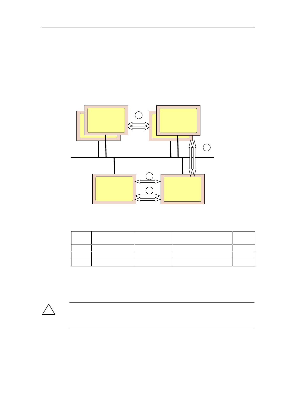
Safety Mechanisms
See Also
Interconnecting F-Driver Blocks and Driver Blocks for F-Signal Modules
3.9.4 Safety-Related Communication Between F-CPUs
Communication Options
1
S7 FH Systems
S7-400FH
S7 FH Systems
S7-400FH
2
3
S7 F Systems
Safety-related communication between CPUs takes place via configured standard or
fault-tolerant S7 connections.
Number Communication
From...
1 S7 FH Systems S7 FH Systems S7 connection, fault-tolerant Yes
2 S7 F/FH Systems S7 F Systems S7 connection, fault-tolerant Yes
3 S7 F Systems S7 F Systems S7 connection Yes
The fail-safe blocks F_SENDBO <-> and F_RCVBO or F_SENDR <-> F_RCVR are
available for safety-related communication between safety programs on different FCPUs. This means a fixed number of parameters of BOOLs or REALs can be safely
transferred
!
Safety Note – Public Network Safety F-CPU Communication Not Allowed
Safety-related communication between F-CPU s is not permissible via public
.
2
S7 F Systems
To Connection Type Safety-
Related
networks.
Fail-Safe Systems
3-12 A5E00085588-03
Page 69

Safety Mechanisms
Note
Multiproject is a new feature of STEP7 V5.2, with this feature, you do not need to
maintain all CPUs in the same project ; and you ma y hav e se ver al pro je cts in whic h
CPU to CPU communication is shared between them.
Communication with Standard CPUs
Direct communication between a Safety Program and a standard CPU is not
possible. Communication can only take place in a standard program on the F-CPU
after the F-data types have been converted into standard data types by means of a
conversion block. Communication in the standard program uses the standard
communication functions.
See Also
Programming Communication Between Safety Programs on Different CPUs
Fail-Safe Systems
A5E00085588-03
3-13
Page 70

Safety Mechanisms
Fail-Safe Systems
3-14 A5E00085588-03
Page 71

4 Configuration
4.1 Overview
This section describes the main differences between the configuration of a fail-safe
system and that of a standard S7 system. It also deals with the special features of
the programming device functions that you must watch out for when working with a
fail-safe system.
4.2 Hardware Configuration and Parameter Assignment
The basic procedure for configuring a fail-safe system doesn’t differ from that of a
standard S7 system, e.g. it comprises the following steps:
• Creating projects and stations
• Configuring hardware and the network
• Downloading the system data to the PLC
The individual steps required for configuration are also largely identical with those
of the S7-400. Authorization is always required to change the parameter
assignment of an F-System.
Rules for F-Systems
In addition to the rules that generally apply to the arrangement of modules in an
S7-400, the following conditions must be complied with in the case of an F-System:
Note: An ET 200S can contain Fail-Safe Modules and Standard Modules.
• In safety mode, fail-safe signal modules can only be used in an ET 200M with
the IM 153-2 FO or a Safety Protector Module. Exception: The S7-300
standard module SM 331; AI 2 x 12Bit (order no. 6ES7 331-7TB00-0AB0) can
be used together with fail-safe signal modules in safety mode in an ET 200M.
• Fail-safe operation of the F-SMs is only possible in the address area 8 to 8191.
The address used must be set on the F-SM by means of switches and must
match the configured address.
• To run a CPU with a Safety Program, the appropriate option must be activated
for the CPU and a password configured.
• If the configuration of an F-I/O or the CPU (cycle times of the cyclic interrupt
OBs) is changed, the Safety Program must be compiled again and downloaded
to the CPU.
Fail-Safe Systems
A5E00085588-03
4-1
Page 72

Configuration
• Before downloading the Safety Program, you must download the configuration
to the CPU.
• If you use a safety protector in the ET 200M, then you can operate fail-safe
signal modules with the S7-300 standard signal modules in an ET 200M even
in safety mode in SIL 3.
• The safety protector protects the fail-safe signal modules from possible
overvoltage in the event of a fault. To do this, the fail-safe signal modules
must be inserted in the ET 200M configuration to the right of the safety
protector, and all the standard signal modules must be inserted to the left of
the safety protector.
The ET 200M components which can be used in safety mode depends on the
safety class and the use of a safety protector in the ET 200M configuration:
• If you comply with the requirements of safety class SIL 2 or use a safety
protector in SIL 3 in ET 200M, you can use the IM 153-2 for S7 F/FH Systems
or the IM 153-3 only for the S7 FH Systems and you can set up the
PROFIBUS-DP with the copper cable (as in standard mode).
• If you don’t use a safety protector in SIL 3 in ET 200M, you must connect the
PROFIBUS-DP lines of the S7 F/FH Systems with fiber optic cables, you can
only use the IM 153-2FO.
Additional Information
You can find a full description of the safety protector in the S7-300 Programmable
Controller, Fail-Safe Signal Modules; A5E00048969-03; edition 02/2001.
!
Safety Note – Safety Rules for Safety Operation
A safe operation is not possible if these rules are not complied with.
Fail-Safe Systems
4-2 A5E00085588-03
Page 73

Configuration
4.3 CPU Parameter Assignment
Rules for Configuration as an F-CPU
!
Safety Note – CPU containing safety program must have a password
The user must comply with the following rules:
• The "CPU Contains Safety Program" option must be selected.
• A password must always be assigned.
You must make these settings v ia the CPU ’s object properties in HWCONFIG.
Procedure
1. Select the desired CPU in HWCONFIG, and then choose the Edit > Object
Properties menu command.
2. Select the protection level you want for the CPU, and then enter a password in
the text boxes provided.
3. Select the "CPU Contains Safety Program" option on the "Protection" tab.
Important Parameters for the CPU in the S7 FH System
To prevent time monitoring during a master/standby switchover, you must
configure the OB3x provided for Safety Programs with a priority > 15 on the "Cyclic
Interrupts" tab.
The cyclic interrupt OB of the Safety Program must be configured as a "Cyclic
Interrupt OB with Special Handling". Only then will this cyclic interrupt be called
during updating of the standby for priority classes > 15 directly before the start of
the blocking time. To do this, go to the "H Parameters" tab in the CPU properties,
and then enter in the "Cyclic Interrupt OB with Special Handling" text box the
number of the highest priority cyclic interrupt OB to which blocks of the Safety
Program section are assigned in CFC.
Fail-Safe Systems
A5E00085588-03
4-3
Page 74

Configuration
4.4 Parameter Assignment of F-I/Os
Additional options are available for parameter assignment of F-I/Os that are not
available for parameter assignment of comparable standard SMs:
• You can select between safety mode (different levels to a certain extent) and
standard mode.
• You can operate F-I/Os redundantly in safety mode to increase availability
(fault tolerance). Redundant modules can be inserted either in the same
mounting rack or in different ones for increased availability. Note: redundancy
is only available in modules wh ic h sup port it.
An F-I/O cannot be addressed directly in safety mode. It can only be addressed via
the fail-safe driver blocks.
Only in the F-I/O can you choose between Safety and Standard-Mode, but not in
the ET 200S F modules.
Dynamic parameter assignment by means of SFC calls is only possible in standard
mode for the F-SM. It is not possible to change to safety mode in this way.
You can find more information on the parameter assignment of F-I/Os in manual /1/
(refer to the references in Appendix B) and in the context-sensitive help information
in HWCONFIG.
Symbolic Names
Note
Enter a symbolic name for each input or output channel of the configured F-I/Os.
In the case of F-I/Os in safety mode, in CFC you must assi gn the s ymb olic na me of
the associated channel to the VALUE input of each F channel driver block.
This enables automatic assignment between the module parameters configured in
HWCONFIG (addresses, monitoring times, etc.) and the I/Os of the associated F
channel driver blocks in CFC.
If you configure 1oo2 sensor evaluation for the digital input modules, we
recommend that you mark the channels that are unavailable (4 to 7 in the SM 326;
DI 8 x NAMUR and 12 to 23 in the SM 326; DI 24 x DC 24 V and the
corresponding chann el in the 4/8 F-DI 24 VDC PROF I saf e) as reser ve d in the
symbol table.
Fail-Safe Systems
4-4 A5E00085588-03
Page 75

Configuration
Entering Module Names
You can enter a module name for an F-I/O In HWCONFIG. This name is copied for
the instance of the associated F module driver (F_Name_x) if the associated F
module driver is placed automatically. This enables the link between the F module
driver and the F-I/O to be seen and checked more easily.
The name entered can have a maximum of 12 characters if the associated
instance names of the F module driver are to be unique.
To do this, proceed as follows:
1. Select the desired F-I/O in HWCONFIG, and then choose the Edit > Object
Properties menu command.
2. Under Name, enter a name for the F-I/O using a maximum of 12 characters.
If the instance name of the F module driver is not unique, you will subsequently
only be able to check the link between the F module driver and the F-I/O via the
logical address.
Group Diagnosis for F-SM
This section is only valid for F-SM. Group Diagnosis in the ET 200S F-Modules
cannot be switched off.
The "Group Diagnosis" parameter switches on and off the transmission of channelspecific diagnostic messages (e.g. wire break, short circuit)
to the CPU. The group diagnosis can be switched off on unused input or output
channels in the interests of availability. This results in the following behavior:
Fail-Safe Input Modules:
If the group diagnoses of the input channels are switched off, safe 0 values are
also sent to the CPU in the event of a fault, but no error messages are sent to the
CPU.
Fail-Safe Output Modules:
The following occurs if there are channel faults at outputs with group diagnosis
switched off:
• In the case of faults with channel-specific switch-off, the affected channels of
the module are not switched off.
• In the case of faults at which the affected module half (DO0...DO4 or
DO5...DO9) is switched off, the affected module half is switched off.
• The CPU does not receive a diagnostic message, and the outputs are not
passivated, depending on the setting on the F-driver block.
of the F-signal modules
!
Fail-Safe Systems
A5E00085588-03
Safety Note – I/O Group Diagnosis
In the case of fail-safe input and output modules in safety mode, group diagnosis
must be set for all the connected channels.
Please check that the switching off of the group diagnosis has really only been set
for unused input and output channels.
4-5
Page 76

Configuration
4.5 Configuring Redundant F-I/Os
(only in supported modules)
Note
In the case of redundantly configured modules, you must make sure of the
following:
• That the two modules are of the same type and have the same parameter
assignment.
• That the same monitoring time is parameterized for both modules.
• That the "Safety Mode" option is selected on the "Inputs" tab.
For example, to configure two ET 200M fail-safe input modules redundantly,
proceed as follows:
1. In HWCONFIG, insert the two F-SMs in the ET 200M(s).
2. Assign parameters to the first module: Select the "Safety Mode" option on the
"Inputs" tab and set any additional par ameters.
3. Assign parameters to the second module: Select the "Safety Mode" option on
the "Inputs" tab and set the same parameters as for the first module.
4. For the second module, set the "Redundancy 2x" option on the "Redundancy"
tab.
5. In the "Find Redundant Module" dialog box, select the module you want.
6. You can set the discrepancy time for redundant digital input modules, if
required.
4.6 Configuring the Networks and Connections
The configuration of networks and connections in a fail-safe system only differs
from that in a standard S7 system in one respect:
The fail-safe function blocks are required for safety-related communication
between CPUs. It is therefore only possible between the Safety Programs on FCPUs.
Fail-Safe Systems
4-6 A5E00085588-03
Page 77

Configuration
4.7 Programming Device Functions in STEP 7
The same functions are available for working with a fail-safe system in STEP 7 as
for a standard S7 system.
Safety-Relevant Programming Device Functions
Safety-relevant programming device functions are only executed if you have set up
access rights for yourself. The following programming device functions are safetyrelevant and can only be executed once authorization has been obtained with a
CPU password, irrespective of the protection level set:
• Downloading of the whole program from CFC or SIMATIC Manager
• Downloading of Safety Program changes from CFC
• Downloading and deletion of F-Blocks from SIMATIC Manager
• Downloading to the EPROM memory card on the programming device
• Memory reset from CFC or SIMATIC Manager
!
Safety Note – Modify Variables can cause Shutdown
You cannot change variables and values on F-Block I/Os online using the PLC >
Monitor/Modify Variables menu command, for example. If such a modification to
an F function block is detected, the Safety Program may be shutdown which will
result in your outputs being disabled.
Setting Breakpoints
Note
After the HOLD mode has been requested, a Restart of the Shutdown Logic is
required.
Fail-Safe Systems
A5E00085588-03
4-7
Page 78

Configuration
4.8 Setting up, Modifying and Cancelling Access Rights
4.8.1 Setting up Access Rights for the CPU
To set up access rights for the CPU, proceed as follows:
1. Select the CPU or its S7 program in SIMATIC Manager.
2. Choose the PLC > Access Right s > Setup menu command. In the dialog
tab box that appears, locate the protection tab and enter the password
assigned during parameter assignment of the CPU.
Access rights are valid until they are canceled (PLC > Access Rights > Cancel )
or until the last S7 application has been terminated.
!
!
Safety Note – Limiting Access through ES
If access to the ES or programming device is not limited by means of access
protection to those individuals authorized to modify Safety Programs, the efficacy
of the password protection must be ensured by means of the following
organizational measures on the ES/programming device:
• The password must only be accessible to people with authorization.
• People with authorization must explicitly cancel the authorization when they
exit the ES/programming device. If this is not rigorously adhered to, a screen
saver with a password accessible only to authorized people must also be used.
When the standard program is change d in safe ty mo de, ac ce s s rights should not
be obtained using the CPU password because otherwise the Safety Program can
also be changed. The protection level must instead be set accordingly.
After access rights have been canceled, check, if safety mode is active, whether
the overall signature of the Safety Program online and the overall signature of the
accepted Safety Program are identical. If not, download the correct Safety
Program to the CPU again (see sections "Downloading Changes" and "Comparing
Safety Programs".
Safety Note – Passw ord Protect ion
After an unbuffered cold restart, the current password is deleted from the RAM
load memory and the old password from the flash EPROM memory card is valid
again. To prevent this old password on the flash EPROM memory card being
known to too many people, you should take organizational measures.
Fail-Safe Systems
4-8 A5E00085588-03
Page 79

Configuration
Changing the Password
A password can only be changed by changing the configuration.
To do this for the S7 F System, you must switch the CPU to STOP.
It is possible to change the password (configuration change) for the S7 FH System
without interrupting the process (in RUN mode).
4.8.2 Entering/Changing the Password for the Safety Program
To enter or change the password for the safety program, proceed as follows:
1. Select the CPU or its S7 program in SIMATIC Manager.
2. Choose the Options > Edit Safety Program menu command.
3. Select the "Password..." button in the Safety Program dialog box that appears,
and perform the appropriate action as listed below:
• Enter the password for the Safety Program for the first time. In this case,
ignore the "Old Password" field.
• Change the existing password for the Safety Program. You must enter the
existing password in the "Old Password" field.
Use the Cancel Access Rights button to immediately stop the one-hour persistence
of Access Rights since the last time the password was entered. Following this, any
user must provide the Safety Program Password explicitly for any operation that
normally requires it, regardless of how much time has passed since the last entry
of the password.
!
Safety Note – Safety Program and CPU Passwords should be different
We recommend you use different passwords for the CPU and for the safety
program for improved access protection.
If you haven’t already entered a password, you will be requested to enter one when
you compile the Safety Program for the first time (see below, "Request for the
Password for the Safety Program".)
You can change the password in the same way as usual under Windows 95/98/NT
by entering the old password once and the new password twice.
The password for the Safety Program is stored offline in the ES/programming
device together with the safety program.
Fail-Safe Systems
A5E00085588-03
4-9
Page 80

Configuration
Request for the Password for the Safety Program
A dialog box to request the password for the safety program is displayed in the
following cases:
• Compilation of changes to the Safety Program
• Switching safety mode on and off
• Downloading of changes to the data of the Safety Program when safety mode
is switched off
• Modification of F constants in CFC test mode
4.8.3 Cancelling Access Rights for the Safety Program
Validity of the Password for the Safety Program
After the password for the safety program has been entered (following a request or
a change), it is valid for an hour. In a session to edit the safety program
(modification, compilation, deactivation of safety mode, downloading of changes),
you only have to enter it once. After an hour you have to enter it again.
You also have to enter the password again if the last of the specified actions during
a session is more than an hour ago.
!
Safety Note – Authorized use of Password
If access to the ES or programming device is not limited by means of access
protection to those individuals authorized to modify Safety Programs, the efficacy
of the password protection must be ensured by means of the following
organizational measures on the ES/programming device:
• The password must only be accessible to people with authorization.
• People with authorization must explicitly cancel the authorization when they
exit the ES/programming device. If this is not rigorously adhered to, a screen
saver with a password accessible only to authorized people must also be used.
Cancelling Access Rights
You can cancel access rights at any time using the password for the Safety
Program. To do this, proceed as follows:
1. Select the CPU or its S7 program in SIMATIC Manager.
2. Choose the Options > Edit Safety Program menu command
3. Click the "Password..." button in the dialog box that appears.
4. In the "Password" dialog box that appears, click the "Cancel Access Rights"
button.
Fail-Safe Systems
4-10 A5E00085588-03
Page 81

Configuration
4.9 Configuration in Run
There are process control systems that may not be switched off during operation,
e.g. due to the complexity of the automated process, or expensive restart costs.
Nevertheless, a change or expansion of the process control system may be
required. Configuration in Run (CiR) makes this possible. The program execution
will be stopped for a certain time up to 2500 ms. During this time, the process
outputs keep their current value. In particular, in process control systems, this has
no effect on the process.
Before using the information below, please review the CiR procedures in the
manual „How to Modify the System during Operation with CiR“.
Calculate the Monitoring Times
When loading a safety program, it is necessary to calculate all safety monitoring
times within the F-System including the CiR Synchronization time in order to
determine which monitoring time settings are necessary to use with CIR. If these
values are unacceptable for the process, you can recalculate the monitoring time
by reducing the CiR Synchronization Time. To reduce the CiR Synchronization
Time, you have the following possibilities:
• reduce the amount of input and output bytes of the master system
• reduce the amount of guaranteed slaves of the master systems to be changed
• reduce the amount of changing master systems within one CiR event
To calculate the safety monitoring times use the spreadsheet:
\\Step7\S7BIN\S7FTIMEB.XLS
Limitation of the CiR Synchronization Time
The F-CPU compares the actual calculated CiR Synchronization Time with the
current upper limit of the CiR Synchronization Time. If the calculated value is less
than the upper limit, the CiR is carried out. The default value of the upper limit of
the CiR Synchronization Time within the CPU is 1 second. This value can be
changed by using the SFC104 to reduce or to enlarge the upper limit in the range
of 200ms to 2500ms. You can find the detailed description of the SFC 104 in the
manual "SIMATIC System Software for S7300/400 System and Standard
Functions“.
Configuration of F-I/O’s via CiR
With CiR you can add a new F-I/O to your System or you can delete an existing FI/O from your System. The following procedures show you how to do this:
Fail-Safe Systems
A5E00085588-03
4-11
Page 82

Configuration
Adding F-I/O’s via CIR
To add a new F-I/O to your System follow these steps:
• Configure the new F-I/O within HWCONFIG according to the manual, “How to
Modify the System during Operation wth CiR (handle it like a standard module)
• Calculate the Monitoring Time for this F-Module (see “Calculate the Monitoring
Time for Communication between the F-CPU and the F-I/O“) and use it to
update the Monitoring Time for this F-Module in HWCONFIG.
• Modify your safety program (add safety logic, channel driver and module driver
for this module)
• Deactivate safety mode (see “Deactivating Safety Mode“)
• Download your safety program
• Download your configurat ion v ia CiR
• Activate safety mode (see “Activating Safety Mode“)
Deleting F-I/O‘s via CiR
To delete an already existing F-I/O from your System follow these steps:
• Delete the F-I/O within HWCONFIG according to the manual, “How to Modify
the System during Operation with CiR“ (handle it like a standard module)
• Modify your safety program (delete safety logic, channel driver and module
driver for this module)
• Deactivate safety mode (see “Deactivating Safety Mode“)
• Download your safety program
• Download your configurat ion v ia CiR
• Activate safety mode (see “Activating Safety Mode“)
Note
You can only delete an existing F-I/O via CiR if the module was added to the
system via CiR.
Changing of an exisiting configuration of an F-I/O is not possible.
Fail-Safe Systems
4-12 A5E00085588-03
Page 83

5 Programming
5.1 Overview
5.1.1 Structure of the Safety Program
The following figure illustrates the structure of a Safety Program in the
programming device/ES and CPU schematically:
Programming device / ES
S7 F System
STEP 7 project
User
Safety
Hardware
Program
Standard
CFC
Standard
F-System
F User’s
Charts
The user program in the CPU is usually made up of a standard and a fail-safe
section. The safety functions are programmed in CFC using fail-safe blocks.
Failsafe Blocks V1_2
Control Blocks
Simulation Blocks
User Blocks
Libraries
Program
F-SMs
Standard
SMs
Fail-Safe Systems
A5E00085588-03
5-1
Page 84

Programming
5.1.2 Blocks of the Safety Program
Fail-Safe Blocks
A Safety Program can contain the following fail-safe blocks:
• Fail-safe blocks that can be inserted by the user (F user blocks)
F User Blocks Function
F-Driver
F_CH_DI
F_CH_AI
F_CH_DO
Conversion
F_BO_FBO
F_I_FI
F_R_FR
F_TI_FTI
F_FBO_BO
F_FI_I
F_FR_R
F_FTI_TI
F_QUITES Fail-safe acknowledgment via the ES/OS
F_FR_FI Conversion from F_REAL to F_INT.
RTG – RTG
Communication
F_S_BO, F_S_R
F_R_BO, F_R_R
CPU – CPU
Communication
F_SENDBO,
F_SENDR
F_RCVBO, F_RCVR
F_START Signals a cold restart or warm restart.
Channel driver for the input and output signals of the F-I/Os
Conversion from standard to F-data types
Conversion from F to standard data types
Communication between F-run-time groups
Communication with Safety Programs on other CPUs
Fail-Safe Systems
5-2 A5E00085588-03
Page 85

Programming
In addition, fail-safe blocks are also available for standard functions such as
arithmetic, logic, multiplexing, etc. You can find a complete list of the fail-safe
blocks in Appendix.
• F Control blocks are automatically inserted during compilation and are never
to be inserted by user.
F Control Blocks Function
F_CYC_CO F cycle time monitoring
F_M_DI4
F_M_DI8
F_M_AI6
F_M_DO10
F_M_DO8
F_PLK
F_PLK_O
F_TESTC Monitoring of the self-tests of the operatin g system
F_TEST Self-tests executed in each cyclic int errupt cycle
F_TESTM Switching of safety mode on and off
F_SHUTDN, DB_INIT,
RTG_LOGIC,
FAIL_MSG
Fmodule driver for PROFIsafe communication with F-I/Os
Logical program execution monitoring and data flow monitoring
Safety Program shutdown and restart logic blocks
• Simulation blocks (F-simulation blocks) that are used in the offline simulation
of the Safety Program with PLCSim 5.0. PLCSim 5.1 does not use the
simulation block s.
Libraries with Different Versions
Several versions of the "Failsafe Blocks" library can exist on a programming
device/engineering system at the same time. However, a Safety Program can only
contain blocks of the same version. Programs that contain blocks from libraries
with different versions cannot be compiled.
Fail-Safe Systems
A5E00085588-03
5-3
Page 86

Programming
5.2 Creating Safety Programs
5.2.1 Creating a Safety Program - Basic Procedure
Prerequisites
• The project structure must be created in SIMATIC Manager. The Safety
Program must be assigned to an F-capable CPU (e.g. a CPU 417- 4H).
• A chart folder must be created for CFC under the S7 program.
• The hardware components of the project and, in particular, the CPU and the F-
signal modules must be configured and assigned parameters.
Basic Procedure
The following basic procedure applies when creating a Safety Program:
Define program structure
Insert CFC charts
Insert run-time groups (applies to CFC V5.2)
Insert F-function blocks
Parameterize and interconnect F-function blocks
Compile Safety Program
Load Safety Program
Test Safety Program
Yes
OK?
No
Change Safety
Program
On-site acceptance of the Safety Program
e.g. by an expert
Fail-Safe Systems
5-4 A5E00085588-03
Page 87

Programming
5.2.2 Safety Notes for Programming
• A Safety Program can only be compiled to be executable under an F-capable
CPU (e.g. CPU 417-4H).
• The Safety Program must be created in CFC using special F-Blocks from the
Failsafe Blocks library. The name of the library must not be changed.
• During compilation the Safety Program is changed automatically, and Fspecific sections are added. These are modified parameter values and
additional blocks. These modifications are visible in the CFC chart.
!
Safety Note – Compiler Generated Values off-limits
Placements, interconnections and parameter assignments of F-Blocks
automatically executed during compilation must not be changed!
• The COMPLEM and PARID structural co mpo nents of F-data types must not be
manipulated.
• Control blocks inse rted automa tically must not be changed.
• Parameters not visible in F blocks and parameters marked as non-
interconnectable (UDA s7_visible, s7_link) must not be interconnected or
parameterized.
Fail-safe blocks must not be manipulated (deleted, inserted) offline or online in the
block container.
Online modifications of the fail-safe I/Os in SIMATIC Manager made, for example,
by controlling variables or forcing are not permissible and will result in a Safety
Progam disable if fail-safe blocks (V1.2) or greater is used.
You must not operate Safety Progra m s dir ect l y when saf et y mode is activat ed! Yo u
can enter safety parameters for unconnected inputs:
• from the standard program, using fail-safe conversion blocks with an
additional plausibility check
• in CFC test mode and with safety mode deactivated.
If you don’t comply with these safety guidelines, you also risk the Safety Progr am
becoming disabled.
Fail-Safe Systems
A5E00085588-03
5-5
Page 88

Programming
Notes on Working With CFC
!
Safety Note – Compression Changes Signature
Compressing CFC programs changes the overall signature of the program!
If the program has to be compressed, carry out the com pr e s sion before it is
accepted.
The fail-safe blocks in the Fail-safe Blocks library are highlighted in color in the
CFC chart. They are colored yellow to indicate that it is a safety program.
The CFC charts and run-time groups with F-Blocks are yellow and marked with an
"F" to differentiate them from the charts and run-time groups of the standard
program.
Fail-Safe Systems
5-6 A5E00085588-03
Page 89

Programming
5.2.3 Defining the Program Structure
Rules for the Program Structure
You must comply with the following rules when you design a user program for the
S7 F/FH Systems:
• You can combine standard and Safety Program sections within a CPU.
• Multiple charts with fail-safe blocks are permissible for each priority class (task
or OB).
• Run-time groups with fail-safe blocks can only be assigned to OB3x cyclic
interrupts (OB 30 to OB 38).
• It is recommended to place all the blocks in a chart, with the exception of the
module driver, in the same run-time group whenever possible. A run-time
group can, however, contain blocks from several charts.
• A chart may contain both F-blocks and standard blocks, as long as the Fblocks are in separate run-time groups from the standard blocks, and as long
as the charts are not compiled as block types.
• You can only access the F-I/Os in the Safety Program via the F channel
drivers, which make the process signals available in the safe data format.
• As of about 1000 blocks, you have to distribute the Safety Program to several
F-run-time groups; otherwise, it can’t be compiled.
• 110 Run-time groups maximum.
Specifications for the Safety Program
When you design a user program for the S7 F/FH Systems, you must also make
the following decisions in addition to what is required for a standard system:
• Which sections of the user program have to be fail-safe?
You must create separate CFC charts and run-time groups for these sections
of the user program.
• Which OB3x cyclic interrupts do the fail-safe sections of the user program have
to be assigned to? With which priorities and cycle times?
You must configure these OBs for the CPU.
Note
You can improve the performance by remo ving the non- sa f et y- relat ed functions
from the Safety Program section and lea ving them in the standard program
section. This particularly includes functions such as reporting, monitoring etc.
When distributing functions between the standard and fail-safe section of the
program, note that it is easier to change the standard section of the program and
download it to the CPU. Changes to the standard section do not normally require
acceptance.
Fail-Safe Systems
A5E00085588-03
5-7
Page 90

Programming
For Fault-Tolerant Systems
In fail-safe and fault-tolerant S7 FH Systems, one or more separate cyclic
interrupts with a high priority should be reserved for the Safety Program. This is
necessary to prevent time monitoring being initiated in the case of a
master/standby switchover. To do this, you must configure the OB3x cyclic
interrupts provided for the Safety Program on the "Cyclic Interrupts" tab in the CPU
properties with a priority > 15. No standard blocks should then be placed in these
OBs.
5.2.4 Inserting CFC Charts
Rules for the CFC Charts of the Safety Program
Please note that separate charts must be created for the fail-safe section of the
user program.
Procedure
You can create individual CFC charts in the chart folder in the usual way:
• By choosing the Insert > S7 Sof t w a re > CFC menu command in SIMATIC
• By choosing the Chart > New menu command in the CFC editor
Chart in Chart
In order to structure a program according, for example, to process-related aspects,
you can use a CFC chart within a CFC chart (Chart in Chart). This enables you to
use solutions already in existence as often as you want. You can find out how to
create Chart in Chart charts, assign them I/Os and insert them in other CFC charts
in the CFC online help system.
Note
If you nest a chart in another chart, you must make sure that the blocks of the
lower-level chart are in the same run-ti me gro up as those of the higher-level chart
(of the basic chart). If necessary, move them. Otherwise, you will receive an error
message when the Safety Program is compiled.
Chart outputs of a lower-level chart that are not interconnected internally cannot be
interconnected further in the higher-level chart.
Manager
Fail-Safe Systems
5-8 A5E00085588-03
Page 91

Programming
5.2.5 Inserting Run-Time Groups
(applies to CFC V5.2 only)
Rules for the Run-Time Groups of the Safety Program
• The F-blocks must not be inserted directly in tasks/OBs; instead, they must be
inserted in run-time groups.
• A separate CFC chart containing the F_CYC_CO block is required for F cycle
time monitoring. In every cyclic interrupt OB to which F-run-time groups are
assigned, this chart must be in a separate run-time group. In the run sequence
of an OB, this run-time group must be called before all the other run-time
groups with F-Blocks of this OB. This is created automatically during
compilation.
• We recommend the following to achieve F cycles of an equal length: If F and
standard run-time groups are combined in a cyclic interrupt OB, the F-run-time
groups should be executed before the standard run-time groups.
Procedure
Note
A Failsafe Run-time group must keep the default values for the Scan and Offset
Run-Time Properties as follows:
Scan = 1
Offset = 0
It is unsafe to change these values, therefore attempting to do this will cause an
error to be posted.
Insert the run-time groups in the CFC run sequence editor in the usual way:
• by choosing the Insert > Run-Time Group menu command, or
• by choosing the pop-up menu command Insert Run-Time Group (right mouse
button)
Specify the run sequence by selecting a run-time group, a chart or a block as
"Predecessor for Installation", using the right mouse button or shift+F11.
Fail-Safe Systems
A5E00085588-03
5-9
Page 92

Programming
5.3 Inserting and Interconnecting Fail-Safe Blocks
5.3.1 Inserting Fail-Safe Blocks
Blocks are inserted in the chart by dragging and dropping them from the F User
Blocks folder of the Failsafe Blocks library. Each block can be inserted as often
as you want.
Note
If a block type has already been inserted from the library, it can be inserted more
quickly the next time from the "CFC Catalog". Note that although fail-safe blocks
and conversion blocks that convert F-data types to standard data types are
distributed to the usual block groups, they are easy to recognize because they are
colored yellow and their names always begin with F_.
Rules for Fail-Safe Blocks
• Fail-safe blocks must be inserted in separate charts in which there must not be
any standard blocks.
• The F blocks in the F Control Blocks folder are automatically inserted when
the chart is compiled; you must not insert these blocks. Exception: Manual
insertion of the F module drivers.
• Fail-safe block’s instances must not be placed in multiple F-run-time groups.
This may occur due to an F-run-time group being copied to or inserted in
another task.
• You must not use the names of the fail-safe blocks for other blocks or rename
the fail-safe blocks.
Safety Note – Symbol Table Entries for F-Blocks cannot be changed
!
The names of the fail-safe blocks in the "Symbol" column of the symbol table of
your user program must not be changed or deleted.
If a change to the block names in the symbol tab le is det ected, the compilation of
the Safety Program is reject ed with the fol low in g error mes sa ge:
"Block type ’xxx’ does not correspond to the standard in the "Fail-safe Blocks
library [Import the block again from the "Fail-safe Blocks" library into the block
catalog and the chart folder of the program]
This also applies to changes in the symbol table assigned to the "Fail-safe Blocks"
block library.
If changes to F-Block names are detected, you can correct the names of the failsafe blocks in the symbol table. You can find the correct names in the "Name
(Header)" text box on the "General" tab in the "Object Properties" dialog box for the
block.
See Also
Fail-Safe Blocks
Fail-Safe Systems
5-10 A5E00085588-03
Page 93

Programming
5.3.2 Automatically Inserted F-Blocks
When a CFC chart with fail-safe blocks is compiled, the following F-Control blocks
are inserted automatically in the Safety Program:
• F_SHUTDN
• DB_INIT
• RTG_LOGIC
• FAIL_MSG (part of RTG_LOGIC block type)
• DB_RES
• F_CYC_CO
• F_PLK
• F_PLK_O
• F_TEST
• F_TESTC
• F_TESTM
The following F module drivers can be inserted automatically (through generate
module drivers) or manually:
• F_M_DI24
• F_M_DI8
• F_M_AI6
• F_M_DO8
• F_M_DO10
!
Safety Note – Do not change automatically inserted F-Control Blocks.
The automatically inserted F-Control Blocks are visible after compilation. You must
not delete or change these blocks in any way. This may result in errors at the next
compilation.
Fail-Safe Systems
A5E00085588-03
5-11
Page 94

Programming
5.3.3 Interconnecting and Assigning Parameters to F-Blocks
You can assign parameters to the inputs and outputs of the F-Blocks or
interconnect them with other blocks.
Rules for Interconnecting F-Blocks
!
Safety Note – Incorrect changes to fail-safe blocks input parameters may
result in the Safety Program and its outputs being disabled.
Changes to fail-safe block input parameters with F-data types can be made in the
following ways:
• Using CFC offline.
• Using CFC test mode with safety mode deactivated.
Online changes made to F-data types when safety mode is activated or by means
other than CFC test mode, will result in a Safety Program and it’s outputs being
disabled.
• Certain inputs and outputs of the fail-safe blocks are automatically supplied
when the charts are compiled. By default, thes e I/Os are not visib le, but they
can be made visible.
• You must not change the I/Os that are supplied automatically. You can find out
whether an I/O is automatically supplied in the block description under FailSafe Blocks or in the online help system.
• EN/ENO I/Os of the F-blocks and run-time group enables must not be
interconnected. EN must not be assigned the value 0 (FALSE).
• We recommend that you do not configure a phase offset or a scan rate for runtime groups. If you do, you must take this into consideration when configuring
the monitoring times.
• Only I/Os with standard data types can be interc onn ected us ing glob al
operands.
• The F-data types are implemented in the program as structures in which only
the first component, Data, has the relevant value.
Note
When you assign parameters to an I/O to which an F-data type is assigned, you
can only assign a value to the first component, DATA. The other components of
the structure are automatica l ly su pp lie d w ith va lue s during compilation of the
program.
Fail-Safe Systems
5-12 A5E00085588-03
Page 95

Programming
Recommendation: meaningful names for placed blocks
Give each block placed a meaningful name. You can choose any name.
Assigning a Value to a Fail-Safe I/O
To assign a value to a fail-safe I/O of an F-Block, proceed as follows:
1. Open the sheet view of the F-Block.
2. Select the I/O and open Object Properties by double-clicking it, for example.
Result: The "Select Structure Element" dialog box appears.
3. Double-click the first structure element in the "Select Structure Element" dialog
4. Enter the desired val ue in the "V al ue " text box and conf irm with "OK".
Fail-Safe Systems
A5E00085588-03
box.
Result: The "Properties – Inputs/Outputs" dialog box appears.
5-13
Page 96

Programming
5. Close the "Select Structure Element" dialog box.
Result: The new value is displayed on the I/O.
See Also
F-Data Types
5.3.4 Defining the Run Sequence
Run-Time Properties
The run-time properties of a block define the position of this block in the
chronological process ing seque nce with in the ov er al l struc ture of the PLC. Thes e
properties are decisive in the behavior of the PLC with regard to response times,
dead times or the stability of time-dependent structures such as control loops.
Each block receives default run-time properties when it is inserted. To do this, you
put it into a task at a position you can set. You can change this installation position
and other attributes to suit your requirements at a later date.
Run Sequence Within a Run-time Group
Note
The run sequence is checked at the beginning of compilation of the Safety
Program. The following F-Blocks are placed in the correct run sequence
automatically when the Safety Program is compiled:
• F Control Blocks including F Module Driver Blocks
• Blocks for F Communication Between CPUs
• F-System Blocks
• Blocks for Converting Data Between Standard and Safety
Sections
You must arrange your blocks in following sequence:
• F Input Channel Drivers (F_CH_DI, F_CH_AI)
• All other F-Blocks not listed in the Note above
• F Output Channel Drivers (F_CH_DO)
After the program is compiled for the first time (or modified), the CFC editor will
automatically place (or adjust) system level run-time groups necessary for the
Safety Program operation. These run-time groups have the ‘@’ symbol preceding
the name of the run-time groups. These run-time groups contain the following
function blocks that are placed automatically:
Fail-Safe Systems
5-14 A5E00085588-03
Page 97

Programming
F_TESTM: Automatic placement of the F_TESTM block and associated chart in
the slowest OB that contains a piece of the failsafe program.
F_CYC_CO: Automatic placement of a F_CYC_CO block and associated chart in
each OB that contains a piece of the failsafe program. The user will be requested
to enter the maximum cycle time (MAX_CYC) at the first compile.
F_TEST/F_TESTC: Automatic placement of the F_TEST and F_TESTC blocks and
associated chart in each OB that contains a piece of the failsafe program.
Shutdown Logic: Automatic placement of the Shutdown Logic for the failsafe
program. This would include all necessary blocks and charts and any connections
to the failsafe RTG’s.
Note
Please note that although the CFC Editor automatically creates the necessary
logic for the user’s Safety Program, it may not delete it once the user deletes the
Safety Program. If the user wishes to delete the Safety Program, the user may
have to manually delete the Safety Program’s system level run-time groups.
You may arrange your fail-safe user logic in any run-time order (following the
above guidelines). You may mix standard and fail-safe run-time groups, as shown
in the graphic below. In the example below, there are three user standard run-time
groups, which are S1, S2, and S3. There are two fails-afe user run-time groups
that are placed and the CFC Editor automatically places the ‘@’ run-time groups.
You should place the fail-safe run-time groups before the standard run-time groups
in the run sequence if possible. This will avoid any variable amounts of delay
encountered when executing the standard run-time groups before the execution of
the fail-safe diagnostics.
Fail-Safe Systems
A5E00085588-03
5-15
Page 98

Programming
Note
Please be aware that by mixing standard and fail-safe run-time groups, you
could possibly jeopar d i ze your ‘MAX_CYC’ maximum cycle time. The more
logic you add to the other run-time groups in the fail-safe OB3x’s, the greater
the chance of encountering a scan overrun if care isn’t taken.
Defining the Run Sequence
Define the run sequence in CFC in the usual way:
1. Choose the Edit > Run Sequence menu command to open the run sequence
view.
2. Drag and drop the blocks in the run-time groups in the required sequence.
5.3.5 Interconnecting F-Driver Blocks
Available F-Driver Blocks
The Fail-safe Blocks (V1_2) library has two types of driver blocks to access the FI/Os:
• F channel drivers to access the input/output channels of the F-I/Os. One F
channel driver block is required for each input or output channel of an F-signal
module used. Exception: Only one F channel driver is required for two
redundant channels. You must insert the required F channel drivers in the CFC
chart.
• F module drivers for PROFIsafe communication between the safety program
and the F-I/Os. One F module driver is required for each module. You can
insert and interconnect the required F module drivers manually or
automatically.
The following F module driver blocks are available:
F-Signal Module F Module Drivers F Channel Drivers
SM 326 DI 8xNAMUR F_M_DI8 F_CH_DI
SM 326 DI 24xDC24V F_M_DI24 F_CH_DI
SM 336 AI 6x13Bit F_M_AI6 F_CH_AI
SM 326 DO 10xDC24V/2A F_M_DO10 F_CH_DO
ET 200S F-DI F_M_DI8 F_CH_DI
ET 200S F-DO F_M_DO8 F_CH_DO
ET 200S PM-E F F_M_DO8 F_CH_DO
ET 200S PM-DF F_M_DO8 F_CH_DO
The F channel drivers must be interconnected with the associated F module driver
via the CHADDRxx I/O. One MOD_D1/D2 module diagnostic block can also be
inserted for each F module driver (see the figures below).
Fail-Safe Systems
5-16 A5E00085588-03
Page 99

Programming
Example: F-Driver for Digital Input Module SM 326 DI 8xNAMUR
Logical address
of the module
F module driver
F_M_DI8
TIMEOUT
LADDR
LADDR_R
CHADDR00
...
CHADDR07
DIAG_1
DIAG_2
Symb. addr.
Chan. 00
Symb. addr.
Chan. 07
F channel driver
F_CH_DI
CHADDR
VALUE
F_CH_DI
CHADDR
VALUE
MOD_D1
Module
diagnostic
Q
QN
...
Q
QN
Channel 00
Channel 07
The F-drivers for the digital input module SM 326 DI 24xDC24V and for the analog
input module SM 336 AI 6x13Bit normally have the same configuration with the
corresponding number of channels.
Example: F-Driver for Digital Output Module SM 326 DO 10xDC24V/2A
Channel 00
Channel 09
F channel driver
F_CH_DO
CHADDR
I
VALUE
...
F_CH_DO
CHADDR
I
VALUE
Module
diagnostic
Symb. addr.
Chan. 00
Symb. addr.
Chan. 09
Logical addr.
of modules
F module driver
F_M_DO10
CHADDR00
...
CHADDR09
TIMEOUT
LADDR
LADDR_R
DIAG_1
DIAG_2
You can find descriptions of the blocks under "Driver Blocks for F-I/Os" or in the
online help system.
Fail-Safe Systems
A5E00085588-03
5-17
Page 100

Programming
Drivers for the F-I/Os in Standard Mode
If you use the F-I/Os in standard mode, you can use the standard channel drivers
from the PCS 7 Driver Blocks library.
Rules for F-Driver Blocks
• The VALUE I/O of the F channel driver must be interconnected with the
symbolic address of the channel. In the case of redundant channels, the
VALUE I/O must be interconnected with the symbolic address of the channel
with the lower address .
• A fail-safe signal on the ACK_REI input of each channel driver is required to
reintegrate an input or output channel. The signal must come from a fail-safe
digital input module or – via the F_QUITES F block – from an ES or OS.
• Sequence: See Defining the Run Sequence.
Prerequisite
Symbolic names: Enter a symbolic name for each channel used. You m us t
allocate this name to the VALUE I/O of the associated F channel driver. We
recommend, for the sake of clarity, that you also enter the unused channels in the
symbol table as reserved or not used.
Procedure
When working with F-driver blocks, proceed as follows:
1. Insert the correct F channel driver for each configured input/output channel.
You only have to insert one F channel driver for each pair of redundant
channels.
2. Interconnect the VALUE I/O in each F channel driver with the symbolic name
of the associated channel. This step is required for all F channel drivers
placed. In the case of redundant modules, interconnect the VALUE I/O with the
lower channel address.
3. Interconnect the following with the required signals:
- the I inputs of the F channel drivers F_CH_DO
- the Q outputs of the F channel drivers F_CH_DI
- the V outputs of the F channel drivers F_CH_AI
These I/Os are F_BOOL or F_REAL types and should only be interconnected with I/Os of
the same type belonging to other fail-safe blocks.
4. Set the relevant ACK_NEC input to "1" if user acknowledgment is required with
automatic reintegration of the channel. The ACK_NEC input is preset with "0"
(optional, see "Passivation and Reintegration").
5. Optional: Evaluate the ACK_REQ output in the standard program or on the OS
to find out if user acknowledgment is required.
Fail-Safe Systems
5-18 A5E00085588-03
 Loading...