

Page 1
Page 2

___________________
___________________
___________________
___________________
___________________
SIMATIC
S7-1500
S7-1500R/H redundant system
Getting Started
10/2018
A5E44910930
Introduction to the example
1
Configuration
2
Programming
3
Commissioning
4
Additional information
5
-AA
Page 3
Siemens AG
Division Digital Factory
Postfach 48 48
90026 NÜRNBERG
GERMANY
A5E44910930-AA
Ⓟ
Copyright © Siemens AG 2018.
All rights reserved
Legal information
Warning notice system
DANGER
indicates that death or severe personal injury will result if proper precautions are not taken.
WARNING
indicates that death or severe personal injury may result if proper precautions are not taken.
CAUTION
indicates that minor personal injury can result if proper precautions are not taken.
NOTICE
indicates that property damage can result if proper precautions are not taken.
Qualified Personnel
personnel qualified
Proper use of Siemens products
WARNING
Siemens products may only be used for the applications described in the catalog and in the relevant technical
ambient conditions must be complied with. The information in the relevant documentation must be observed.
Trademarks
Disclaimer of Liability
This manual contains notices you have to observe in order to ensure your personal safety, as well as to prevent
damage to property. The notices referring to your personal safety are highlighted in the manual by a safety alert
symbol, notices referring only to property damage have no safety alert symbol. These notices shown below are
graded according to the degree of danger.
If more than one degree of danger is present, the warning notice representing the highest degree of danger will
be used. A notice warning of injury to persons with a safety alert symbol may also include a warning relating to
property damage.
The product/system described in this documentation may be operated only by
task in accordance with the relevant documentation, in particular its warning notices and safety instructions.
Qualified personnel are those who, based on their training and experience, are capable of identifying risks and
avoiding potential hazards when working with these products/systems.
Note the following:
documentation. If products and components from other manufacturers are used, these must be recommended
or approved by Siemens. Proper transport, storage, installation, assembly, commissioning, operation and
maintenance are required to ensure that the products operate safely and without any problems. The permissible
All names identified by ® are registered trademarks of Siemens AG. The remaining trademarks in this publication
may be trademarks whose use by third parties for their own purposes could violate the rights of the owner.
We have reviewed the contents of this publication to ensure consistency with the hardware and software
described. Since variance cannot be precluded entirely, we cannot guarantee full consistency. However, the
information in this publication is reviewed regularly and any necessary corrections are included in subsequent
editions.
for the specific
09/2018 Subject to change
Page 4

Table of contents
1 Introduction to the example ..................................................................................................................... 4
2 Configuration ........................................................................................................................................ 19
3 Programming ........................................................................................................................................ 34
4 Commissioning ..................................................................................................................................... 48
5 Additional information ............................................................................................................................ 51
1.1 Security information .................................................................................................................. 5
1.2 Structure and task of the example ............................................................................................ 6
1.3 Procedure ............................................................................................................................... 11
1.4 Requirements .......................................................................................................................... 12
1.5 Wiring diagram for a tunnel section ........................................................................................ 13
2.1 Configuring the assembly ....................................................................................................... 19
2.2 Configuring H CPUs ................................................................................................................ 22
2.3 Configuring ET 200SP ............................................................................................................ 25
2.4 Configuring HMI devices ......................................................................................................... 30
S7-1500R/H redundant system
Getting Started, 10/2018, A5E44910930-AA
3
Page 5

1
S7-1500R/H redundant system
Basic knowledge required
WARNING
Personal injury and damage to property may occur.
Redundant automation systems are used in practice to achieve greater availability. In
redundantly operated systems, failure or malfunction of individual automation components
must not impede the operation of the plant.
For the S7-1500R/H redundant system, the CPUs are duplicated, in other words redundant.
The two CPUs process the same project data and the same user program in parallel. The
two CPUs are synchronized over redundancy connections. If one CPU fails, the other CPU
maintains control of the process.
The Getting Started guides you through the configuration and programming of an S7-1500H
redundant system using a concrete example. The following knowledge is required in order to
understand the Getting Started:
● General knowledge of automation technology
● Knowledge of requirements for high availability of automation systems
● Knowledge of the engineering system STEP 7 V15.1
The S7-1500 as a component of plants or systems is governed by specific standards and
regulations, based on the relevant field of application. Please observe the applicable safety
and accident prevention regulations such as IEC 60204-1 (general machine safety
requirements).
The example in this Getting Started serves as an introduction to the configuration and
programming of an S7-1500H redundant system. It cannot always and in every case be
transferred to effective live operations. Before you do this, you are urgently advised to
consult the current version of the system manual "SIMATIC S7-1500R/H redundant
system" and the device manuals of the modules used. The warnings and other information
there must be observed, even if they are not repeated in this Getting Started.
Failure to observe these regulations can result in serious injuries and damages to
machinery and facilities.
S7-1500R/H redundant system
4 Getting Started, 10/2018, A5E44910930-AA
Page 6

Introduction to the example
1.1
Security information
1.1 Security information
Siemens provides products and solutions with industrial security functions that support the
secure operation of plants, systems, machines and networks.
In order to protect plants, systems, machines and networks against cyber threats, it is
necessary to implement – and continuously maintain – a holistic, state-of-the-art industrial
security concept. Siemens' products and solutions constitute one element of such a concept.
Customers are responsible for preventing unauthorized access to their plants, systems,
machines and networks. Such systems, machines and components should only be
connected to an enterprise network or the internet if and to the extent such a connection is
necessary and only when appropriate security measures (e.g. firewalls and/or network
segmentation) are in place.
For additional information on industrial security measures that may be implemented, please
visit (https://www.siemens.com/industrialsecurity).
Siemens' products and solutions undergo continuous development to make them more
secure. Siemens strongly recommends that product updates are applied as soon as they are
available and that the latest product versions are used. Use of product versions that are no
longer supported, and failure to apply the latest updates may increase customers' exposure
to cyber threats.
To stay informed about product updates, subscribe to the Siemens Industrial Security RSS
Feed under (https://www.siemens.com/industrialsecurity).
S7-1500R/H redundant system
Getting Started, 10/2018, A5E44910930-AA
5
Page 7
Introduction to the example
1.2
Structure and task of the example
Automation task light and fan control in a tunnel
Control of the safety ventilation as a function of the air pollution level in the tunnel
Control of the traffic lights and the barriers as a function of the air pollution level in the tunnel
Control of the lighting in the tunnel as a function of the illuminance of the outdoor light
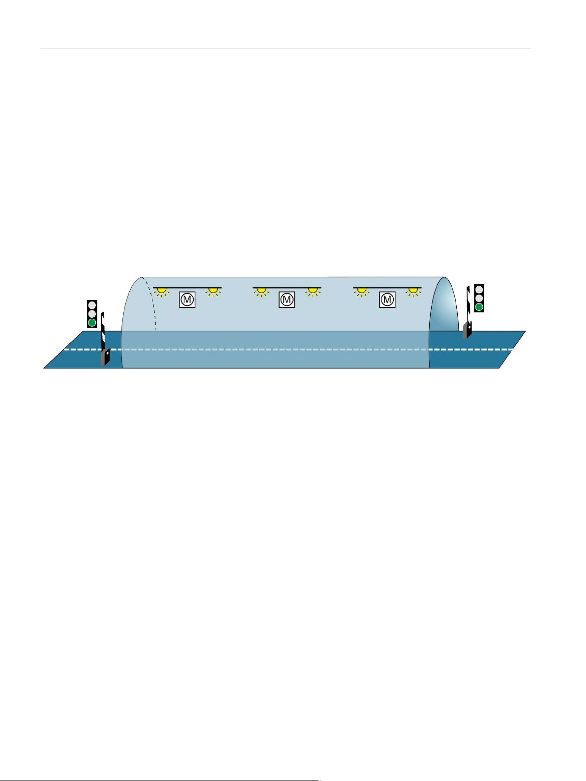
1.2 Structure and task of the example
The continuing increase in traffic volumes coupled with growing safety requirements demand
state-of-the-art tunnel systems. At the same time, equipment requirements for these
constructions are rising, especially when it comes to maximum safety and availability.
The example below comprises three subtasks:
● Control of the safety ventilation as a function of the air pollution level in the tunnel
● Control of the traffic lights and the barriers as a function of the air pollution level in the
tunnel
● Control of the lighting in the tunnel as a function of the illuminance of the outdoor light
Figure 1-1 Example Light and fan control tunnel
Fans are used in the tunnel to extract harmful exhaust gases and supply fresh air.
Uninterrupted operation of the ventilation system is required to keep the concentration of
pollutants below a set level. Constant availability must be ensured for the event that
individual automation components fail, for example because of a fire in the tunnel. The S71500H redundant system with two redundant H-CPUs is used to ensure fan availability.
Three fans ventilate the tunnel.
The tunnel entries are controlled via two traffic lights. The traffic light control also requires
higher availability for safety reasons.
If the pollutant concentration exceeds a maximum limit for more than 2 minutes in a tunnel
section, then the tunnel is blocked.
The abrupt transition between light and dark at the entry to the tunnel is compensated for by
tunnel lighting in the various tunnel sections. Two light sensors measure the light intensity
outside the tunnel. The light intensity of the entry lights in the tunnel is controlled accordingly.
The interior lights in the tunnel are controlled by the prevailing daytime / nighttime.
S7-1500R/H redundant system
6 Getting Started, 10/2018, A5E44910930-AA
Page 8
Introduction to the example
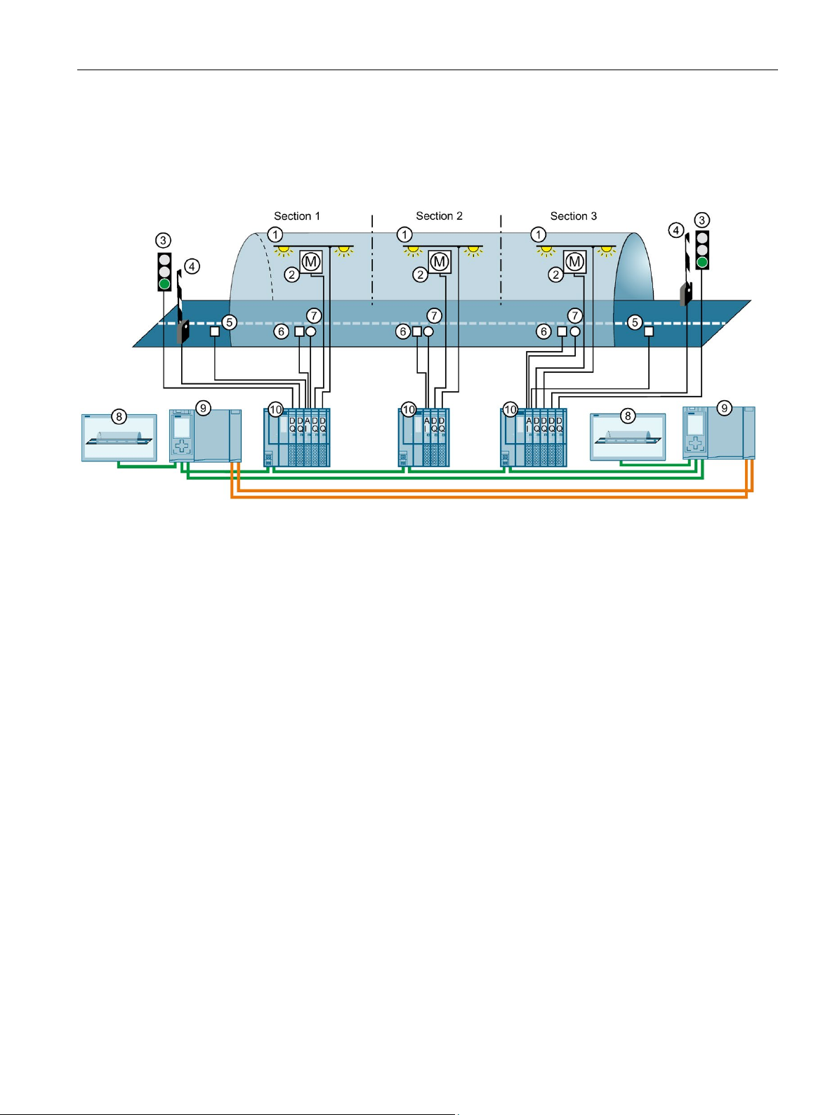
Technology diagram
①
Tunnel lighting
②
Fan ③ Traffic lights
④
Barriers
⑤
Outdoor light sensors
⑥
Turbidity sensors
⑦
Air-quality sensors
⑧
HMI devices
⑨
H-CPUs
⑩
IO devices for tunnel sections 1 to 3
1.2 Structure and task of the example
The technology diagram below shows the structure of the automation solution.
Figure 1-2 Technology diagram
S7-1500R/H redundant system
Getting Started, 10/2018, A5E44910930-AA
7
Page 9

Introduction to the example
Automation components of the example
2 S7-1500 H-CPUs
3 ET 200SP as IO devices in the PROFINET ring
2 Comfort Panels
1.2 Structure and task of the example
The configuration consists of:
● When a CPU fails in redundant operation, the other CPU maintains control over the
tunnel operation.
An ET 200SP (IO device) distributed I/O system is found in every tunnel section (1 to 3).
Sensors and actuators are connected to each IO device for the following tasks:
● Measurement of the pollutant concentration and as a function thereof:
– Control of the fan speed and air flow
– Control of the traffic lights and barriers
● Measurement of the light outside the tunnel:
– Control of the entry lights
● Control of the interior lights in the tunnel, depending on the day / night time.
The Comfort Panels are used by operators as a control center for monitoring tunnel
operation.
S7-1500R/H redundant system
8 Getting Started, 10/2018, A5E44910930-AA
Page 10

Introduction to the example
Principle of operation
Controlling the speed of the fans and controlling the traffic lights and barriers
Controlling the lighting in the tunnel
The user program
The Comfort Panels
1.2 Structure and task of the example
Every fan:
● has two speeds (stages), which are switched on or off depending on the measured
pollutant concentration.
● has 2 directions of rotation. Depending on whether pollution is measured, the fan must
blow or suck.
The H-CPU measures the pollutant concentrations in the tunnel via analog input modules
and air-quality sensors.
If the pollutant concentration exceeds the maximum limit, the H-CPU responds in ET 200SP
via digital output modules as follows:
● It increases the speed of the fan motors
● It switches the traffic light system to red after two minutes
● It closes the barriers after two minutes
If the pollutant concentration falls below an average limit, the H-CPU responds in ET 200SP
via digital output modules as follows:
● It switches the ventilation motors to stop
● It switches the traffic lights to green
● It opens the barriers
The H-CPU measures the light intensity outside and inside the tunnel using analog input
modules. Depending on the outdoor light, digital output modules adjust the brightness of the
entry lights in the tunnel to the optimum vision conditions. The digital output modules also
control the interior lights in the tunnel, depending on the day / night time.
in the CPU specifies limits and controls the input and output modules of
the ET 200SP.
visualize the S7-1500H redundant system in an HMI screen. If required,
the operator can switch to manual operation via the HMI screen and change limit values.
S7-1500R/H redundant system
Getting Started, 10/2018, A5E44910930-AA
9
Page 11

Introduction to the example
S7-1500H versus S7-1500R
Advantages and benefits of the solution
1.2 Structure and task of the example
As an alternative to S7-1500H, you can use an S7-1500R redundant system for the solution
to the automation task. In this example, the S7-1500H redundant system is used as it offers
the following advantages for tunnel automation:
● much higher performance than S7-1500R with:
– separate redundancy connections over fiber-optic cable
– high computing power
– a higher number of PROFINET devices can be used
● distance between the two H CPUs up to 10 km
● High availability of the system: If an H-CPU fails or is being maintained, the lighting and
fan control continues to function. The tunnel does not need to be blocked.
● Reliable monitoring and control of the tunnel facilities over large distances, up to 10 km
between the two H-CPUs
● Monitoring of the system and targeted information of the operating engineers in real time
● Signals are recorded and output directly in the ET 200SP distributed I/O systems in the
tunnel. There are no long cable runs.
S7-1500R/H redundant system
10 Getting Started, 10/2018, A5E44910930-AA
Page 12

Introduction to the example
1.3
Procedure
Tasks
Step
Procedure
Further information
I/O modules and 2 Comfort Panels.
tion (Page 13)
1.3 Procedure
Perform the following tasks for implementation of the example:
Table 1- 1 Procedure for tunnel automation
1 Configure hardware in STEP 7:
Configure the assembly with 2 H-CPUs, 3 ET 200SP stations with their
2 Creating a user program in STEP 7:
• Program the user program in an organization block.
• You create an HMI screen.
3 Installing modules and wiring the assembly:
• Install all modules.
• Wire the load current supply, the modules in the PROFINET ring,
the redundancy connections and the Comfort Panels.
4 Commissioning the example:
• Insert the SIMATIC memory cards in the H-CPUs.
• Switch on the load current supply and the CPUs.
• Assign redundancy IDs to the CPUs in the configuration on com-
missioning.
• Load the project data (hardware configuration and user program) to
the CPUs.
• Check the LEDs and evaluate the information on the CPU displays.
• Test how the example works.
Section Configuring (Page 19)
Section Programming (Page 34)
Redundant System S7-1500R/H
(https://support.industry.siemens.com/cs/
ww/en/view/109754833) system manual
ET 200SP Distributed I/O System
(https://support.industry.siemens.com/cs/
ww/en/view/58649293) system manual
Chapter Wiring diagram for a tunnel sec-
Chapter Commissioning (Page 48)
S7-1500R/H redundant system
Getting Started, 10/2018, A5E44910930-AA
11
Page 13

Introduction to the example
1.4
Requirements
Requirements for the Example
Hardware/software
Modules//Versions
2 ET 200SP for tunnel sections 1 and 3 each consisting of:
1 ET 200SP for tunnel section 2 consisting of:
2 HMI devices
TP1900 Comfort
S7-1500R/H
ET 200SP
Accessories
1 mounting rail, 2 fiber-optic cables, PROFINET cables
the PG/PC
1.4 Requirements
The following hardware and software is available for processing the example:
Table 1- 2 Hardware/software requirements
2 H-CPUs with synchronization modules and SIMATIC
Memory Cards
3 ET 200SP distributed I/O
systems
• 2 identical 1517H-3 PN CPUs with identical article numbers, function versions and firm-
ware version
• 4 synchronization modules for cables up to 10 km in length (6ES7960-1FB00-0AA5)
• 2 SIMATIC Memory Cards e.g. with 256 Mbyte capacity (6ES7954-8LL02-0AA0)
• 1 interface module IM 155-6 PN HF (6ES7155-6AU01-0CN0), FW version V4.2 or later
(with system redundancy S2)
• 4 digital output modules:
– 2 DQ 4x24VDC/2A ST each with a light-colored BaseUnit, BU type A0: BU15-
P16+A0+2D
– 1 DQ 4x24VDC/2A ST with a dark-colored BaseUnit, BU type A0: BU15-P16+A0+2B
– 1 DQ 4x24..230VAC/2A HF with a light-colored BaseUnit, BU type U0: BU20-
P16+A0+2D
• 1 analog input module:
– AI 4xU/I 2-wire ST with a dark-colored BaseUnit, BU type A0: BU15-P16+A0+2B
• 1 server module
• 1 interface module IM 155-6 PN HF (6ES7155-6AU01-0CN0), FW version V4.2 or later
(with system redundancy S2)
• 2 digital output modules:
– 1 DQ 4x24VDC/2A ST with a light-colored BaseUnit, BU type A0: BU15-P16+A0+2D
– 1 DQ 4x24..230VAC/2A HF with a light-colored BaseUnit, BU type U0: BU20-
P16+A0+2D
• 1 analog input module:
– AI 4xU/I 2-wire ST with a dark-colored BaseUnit, BU type A0: BU15-P16+A0+2B
• 1 server module
2 load current supplies for
3 load current supplies for
PC/PG with EngineeringSystem
Switch for the connection of
S7-1500R/H redundant system
PM 190 W 120/230 V AC
Load current supplies with 24 V DC output voltage (with safe electrical isolation)
PG/PC with Ethernet interface and the following correctly installed software package:
• SIMATIC STEP 7 Professional, V15.1 or later
SCALANCE X-204IRT
12 Getting Started, 10/2018, A5E44910930-AA
Page 14

Introduction to the example
Additional requirement
Installing modules and wiring the assembly
Conventions
1.5
Wiring diagram for a tunnel section
Introduction
1.5 Wiring diagram for a tunnel section
The PG/PC is connected to a switch via the PROFINET interface. The switch is a device in
the PROFINET ring during commissioning.
You can set up and wire the hardware before or after configuration and programming of the
user program.
You can find additional information on installation and wiring of an ET 200SP in the
ET 200SP distributed I/O system
(https://support.industry.siemens.com/cs/ww/en/view/58649293) system manual .
The wiring diagram for an ET 200SP for a tunnel section can be found in the section Wiring
diagram for a tunnel section (Page 13).
The procedure for installation and wiring of an S7-1500R/H redundant system is available in
the S7-1500R/H redundant system
(https://support.industry.siemens.com/cs/ww/en/view/109754833) system manual.
Steps and settings which are specific for configuration and programming of an S7-1500H
redundant system will be dealt with in detail in the following sections. Procedures which you
are already familiar with from configuring and programming a SIMATIC S7-1500 will only be
briefly outlined.
The figures below show the wiring of the I/O modules of an ET 200SP distributed I/O system
for tunnel section 1 or 3.
When wiring the tunnel section 2, there is no wiring of the digital output modules for the
traffic lights control and barrier control nor of the outdoor light sensor on the analog input
module.
S7-1500R/H redundant system
Getting Started, 10/2018, A5E44910930-AA
13
Page 15
Introduction to the example
Connecting the supply voltage, PROFINET cables and grounding
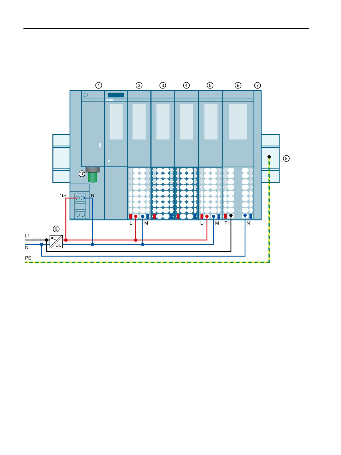
①
Interface module IM 155-6 PN HF (6ES7155-6AU01-0CN0 firmware version V4.2 and later)
②
type A0)
③
type A0)
④
seUnit BU15-P16+A0+2B (BU type A0)
⑤
(BU type A0)
⑥
P16+A0+2D (BU type U0)
⑦
Server module
⑧
Mounting rail grounded at PE
⑨
Load current supply with 24 V DC output voltage (with safe electrical isolation)
⑩
PROFINET cables for the PROFINET ring
1.5 Wiring diagram for a tunnel section
The following figure shows the wiring of the supply voltage, the PROFINET cables and the
grounding on the ET 200SP.
Traffic light control: DQ 4x24VDC/2A ST digital output module with a light-colored BaseUnit BU15-P16+A0+2D (BU
Barrier control: DQ 4x24VDC/2A ST digital output module with a dark-colored BaseUnit BU15-P16+A0+2B (BU
Measuring the light intensity and air pollution level: 4xU/I 2-wire ST analog input module with a dark-colored Ba-
Fan control system: DQ 4x24VDC/2A ST digital output module with a light-colored BaseUnit BU15-P16+A0+2D
Light control system: DQ 4x24..230VAC/2A HF digital output module with a light-colored BaseUnit BU20-
Figure 1-3 Wiring diagram
S7-1500R/H redundant system
14 Getting Started, 10/2018, A5E44910930-AA
Page 16

Introduction to the example
Connecting traffic light control
Connecting barrier control
1.5 Wiring diagram for a tunnel section
The following figure shows the wiring of the traffic lights on the DQ 4x24VDC/2A ST digital
output module
Figure 1-4 Wiring of the traffic lights
②.
The following figure shows the wiring of the barrier control on the DQ 4x24VDC/2A ST digital
output module
The barrier is opened and closed via a three-phase motor. The direction of rotation of the
three-phase motor is controlled via a reversing contactor:
● Open barrier → Contactor K1 actuated
● Close barrier → Contactor K2 actuated
If the barriers have reached their respective end position, they automatically switch off via
limit switches.
③.
Figure 1-5 Wiring of the barrier control
S7-1500R/H redundant system
Getting Started, 10/2018, A5E44910930-AA
15
Page 17
Introduction to the example
Connecting sensors for light intensity and air pollution level
1.5 Wiring diagram for a tunnel section
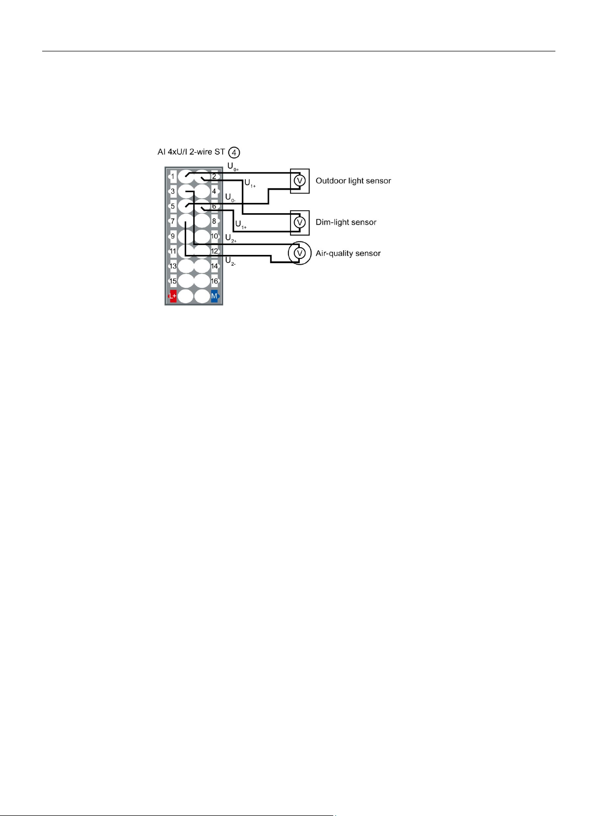
The following figure shows the wiring of the sensors for measuring the light intensity and air
pollution level on the AI 4xU/I 2-wire ST analog input module
Figure 1-6 Wiring of sensors for light intensity and air pollution level
④.
S7-1500R/H redundant system
16 Getting Started, 10/2018, A5E44910930-AA
Page 18
Introduction to the example
Connect light control function
1.5 Wiring diagram for a tunnel section
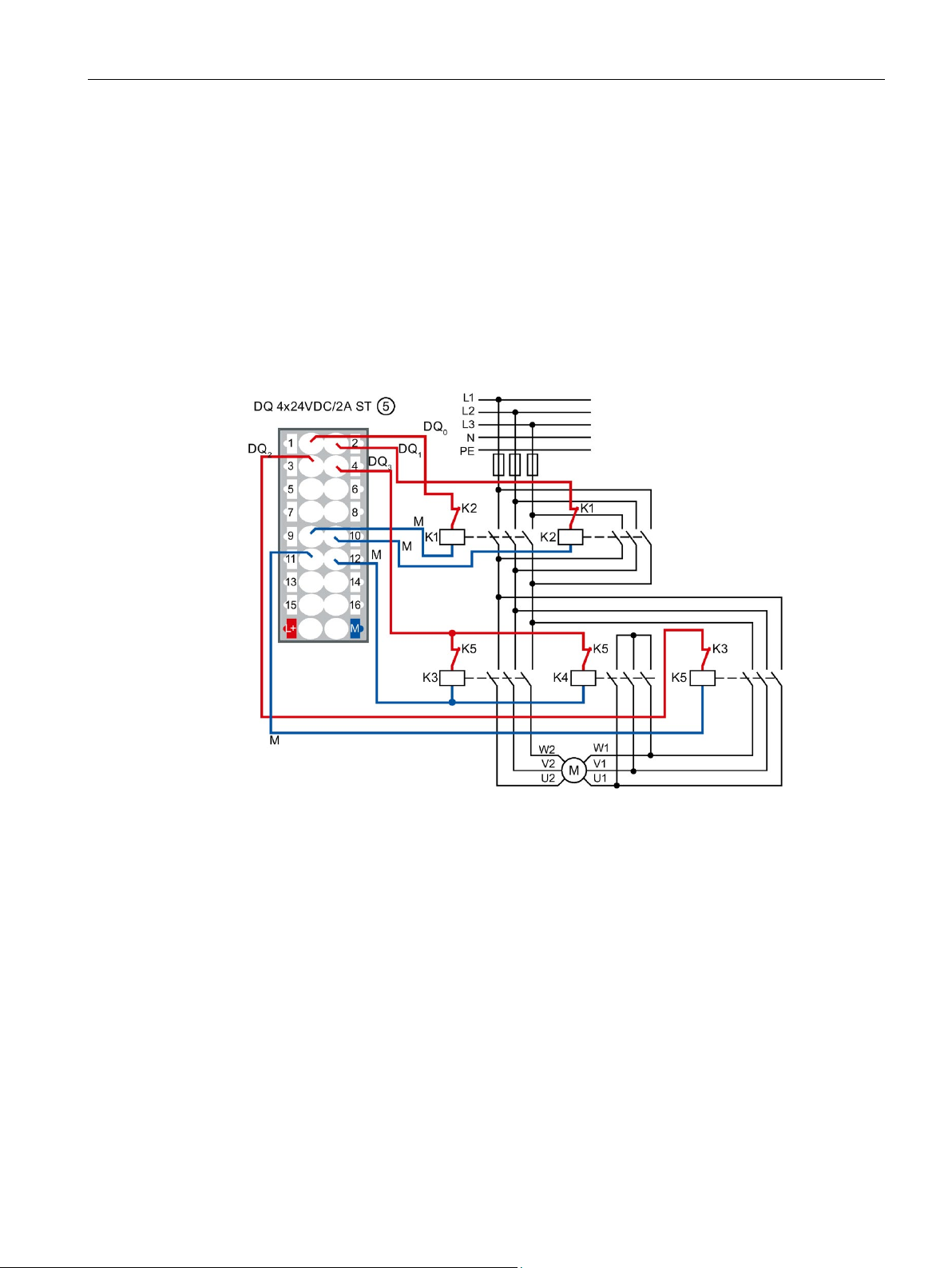
The following figure shows the wiring of the fan control on the DQ 4x24VDC/2A ST digital
output module
The direction of rotation of the fan (right/left) is controlled via a reversing contactor:
● Fan rotates clockwise → Contactor K1 actuated
● Fan rotates counterclockwise → Contactor K2 actuated
The speed (high/low) of the fan is controlled via a Dahlander circuit:
● Fan low speed → Contactor K5 actuated
● Fan high speed → Contactors K3 and K4 actuated
⑤.
Figure 1-7 Wiring of fan control
S7-1500R/H redundant system
Getting Started, 10/2018, A5E44910930-AA
17
Page 19
Introduction to the example
Connect light control function
1.5 Wiring diagram for a tunnel section
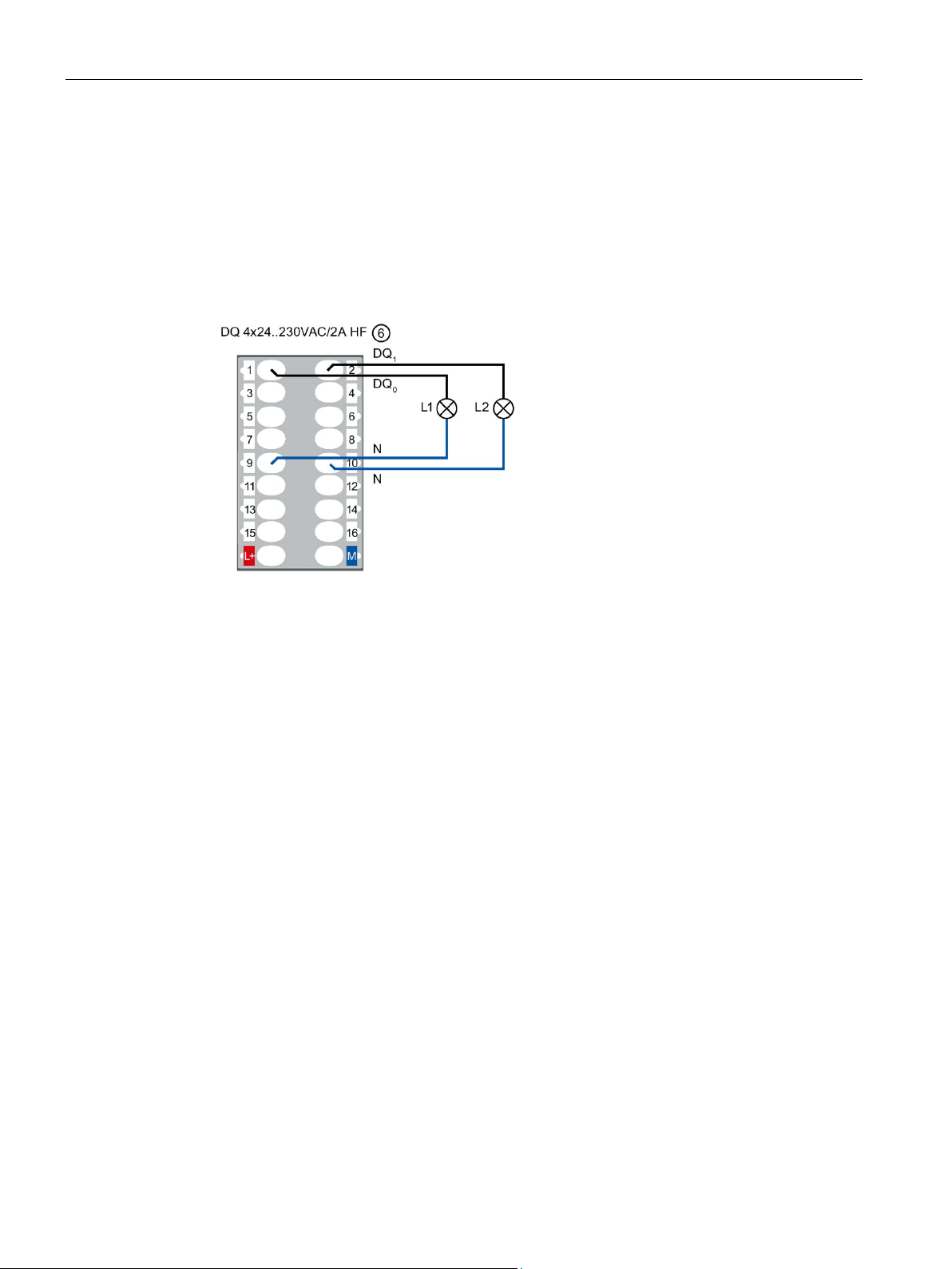
The following figure shows the wiring of the light control on the DQ 4x24..230VAC/2A HF
digital output module
The lamps are dimmed via the Phase angle control - Phase angle proportional function of
the digital output mode:
● L1 → Entry light
● L2 → Interior light
⑥.
Figure 1-8 Wiring of the traffic lights
S7-1500R/H redundant system
18 Getting Started, 10/2018, A5E44910930-AA
Page 20
2
2.1
Configuring the assembly
Introduction
Requirement
Creating a project and assigning hardware
Create a new project and add the CPU 1517H-3 PN and the 3 ET 200SP distributed I/O
systems. Network the assembly to a PROFINET ring.
Add 2 HMI devices TP1900 Comfort to the assembly.
You do not configure the PM 190 W 120/230 V AC load current supplies.
You have set the IP address of the PG/PC, 192.168.0.50 in the example.
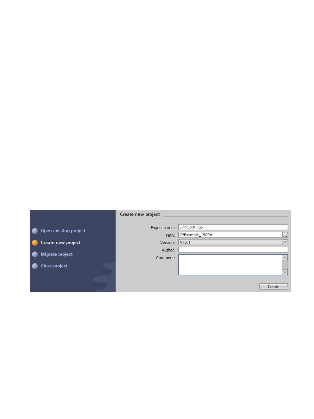
1. Create a new project in STEP 7. Give the project the name "S7-1500H_GS".
Figure 2-1 Creating a new project
2. Select "Configure a device" and then "Configure networks".
The network view opens.
3. Select CPU 1517H-3 PN from the hardware catalog in the network view.
S7-1500R/H redundant system
Getting Started, 10/2018, A5E44910930-AA
19
Page 21
Configuration
Results:
Recommendation:
Results:
2.1 Configuring the assembly
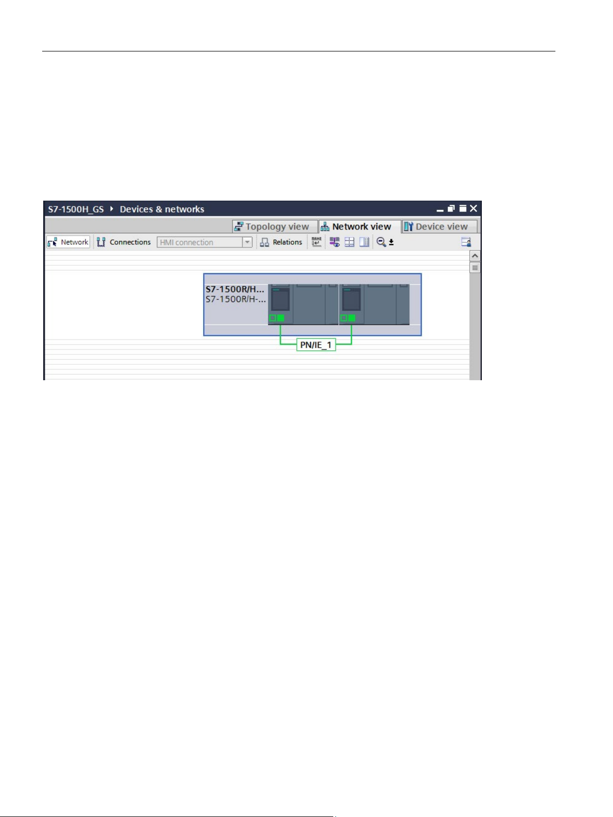
4. Drag and drop the CPU to the task window in the network view.
– STEP 7 automatically creates both 1517H-3 PN CPUs for the redundant system.
– STEP 7 automatically assigns the MRP role "Manager (auto)" to the PROFINET
interfaces X1 of both CPUs.
– STEP 7 displays both CPUs in the network view graphically.
Figure 2-2 CPUs in the network view
5. Select an ET 200SP interface module IM 155-6 PN HF (article number 6ES7155-6AU010CN0) from the hardware catalog.
6. Drag and drop the interface module to the task window in the network view.
7. Drag and drop 2 further IM 155-6 PN HF interface modules to the task window in the
network view.
8. Select a SIMATIC Comfort Panel TP1900 Comfort from the hardware catalog as an HMI
device.
Configure the HMI devices with the HMI Device Wizard (Page 30).
9. Drag and drop the TP1900 Comfort to the task window in the network view.
10.Drag and drop a further TP1900 Comfort to the task window in the network view.
The project has been created. The hardware components have been inserted. IP
addresses for the PROFINET interfaces of the devices have been automatically assigned.
S7-1500R/H redundant system
20 Getting Started, 10/2018, A5E44910930-AA
Page 22
Configuration
Assign ET 200SP with system redundancy S2
Result
2.1 Configuring the assembly
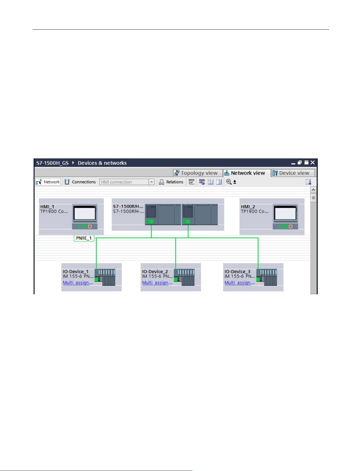
To assign the ET 200SP distributed I/O systems to S7-1500H on a system-redundant basis,
connect every IM 155-6 PN HF interface module to every CPU.
To do so, proceed as follows:
1. Drag-and-drop a line between the PROFINET interface of IM 155-6 PN HF and
PROFINET interface X1 of the left-hand CPU.
2. Drag-and-drop a line between the PROFINET interface of IM 155-6 PN HF and
PROFINET interface X1 of the right-hand CPU.
3. Assign the two other IM 155-6 PN HF devices to the two CPUs in exactly the same way.
: The distributed I/O system ET 200SP are connected to S7-1500H on a system-
redundant basis.
Figure 2-3 ET 200SP assigned to S7-1500H on a system-redundant basis
S7-1500R/H redundant system
Getting Started, 10/2018, A5E44910930-AA
21
Page 23

Configuration
2.2
Configuring H CPUs
Introduction
2.2 Configuring H CPUs
You create two redundancy connections between the H-CPUs via fiber-optic cables using a
total of four synchronization modules (two in each H-CPU). You replace the synchronization
modules (for cables up to 10 km in length) in STEP 7.
STEP 7 automatically assigns an IP address to each PROFINET interface of a CPU. You
can also assign the IP addresses manually. For PROFINET interface X1 of the CPUs, the IP
addresses must be located in the same subnet. In the example you accept the preset IP
addresses.
STEP 7 assigns default values for the minimum and maximum cycle times. Select the
minimum scan cycle time so that the cyclic program does not have to be executed more
frequently than your process requires.
S7-1500R/H redundant system
22 Getting Started, 10/2018, A5E44910930-AA
Page 24
Configuration
Assigning synchronization modules to the H-CPUs
Result
2.2 Configuring H CPUs
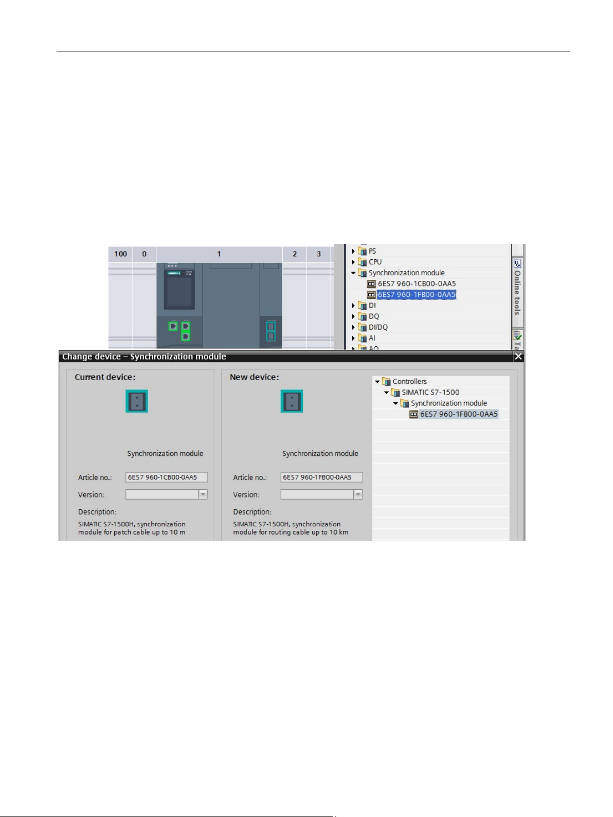
In STEP 7 synchronization modules for 10 m length are assigned to the H-CPUs (default
setting).
For the tunnel application, assign synchronization modules for cables up to 10 km in length
(6ES7960-1FB00-0AA5) to the H-CPUs as follows:
1. Change to the device view of an H-CPU.
2. From the hardware catalog, drag and drop the synchronization module with the article
number 6ES7960-1FB00-0AA5 to the interface for a synchronization module of the HCPU.
3. The "Replace device- Synchronization module" dialog opens. Confirm the replacement
with "OK".
Figure 2-4 Assigning a synchronization module to the H-CPU
: The four synchronization modules for cables up to 10 km in length have been
assigned to the H-CPUs of the redundant system.
S7-1500R/H redundant system
Getting Started, 10/2018, A5E44910930-AA
23
Page 25
Configuration
Setting the cycle monitoring time
Result
2.2 Configuring H CPUs
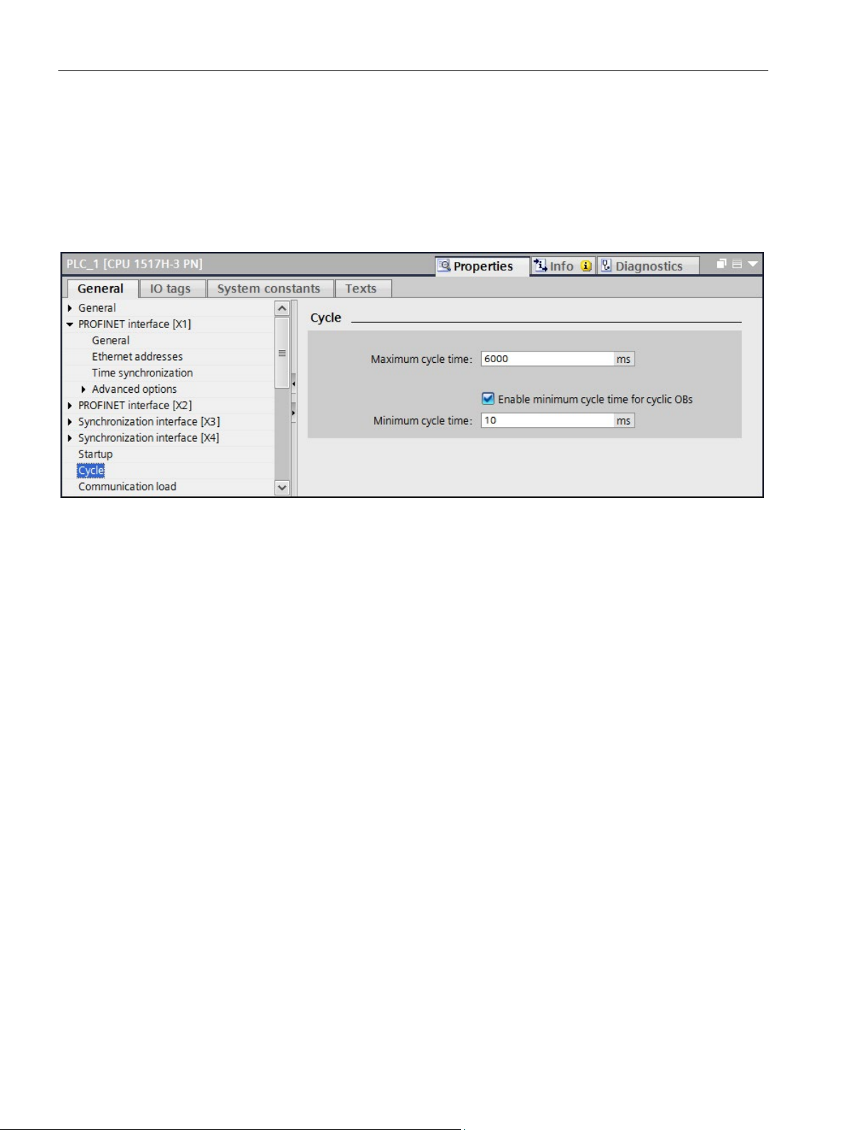
The default values are displayed in the "Cycle" area of the CPU properties.
1. Set a maximum cycle time of 6000 ms and a minimum cycle time of 10 ms for the
example.
2. Adopt the presets for the other parameters.
Figure 2-5 Setting the cycle monitoring time
: When you change the parameters described above for a CPU, the parameters are
automatically adopted in STEP 7 for the other CPU of the redundant system.
S7-1500R/H redundant system
24 Getting Started, 10/2018, A5E44910930-AA
Page 26
Configuration
2.3
Configuring ET 200SP
Introduction
Defining MRP role for ET 200SP in the PROFINET ring
2.3 Configuring ET 200SP
In the S7-1500H redundant system the devices communicate in a PROFINET ring via MRP.
Define the media redundancy role of the devices.
Assign the I/O modules for the various automation tasks in the three tunnel sections to the
three ET 200SP distributed I/O systems.
Set the watchdog time for each ET 200SP. If you set a higher watchdog time, then a failure
of the IO device on interruption of the PROFINET ring can be avoided.
Proceed as follows to define the media redundancy role for the ET 200SP distributed I/O
systems as devices in the ring:
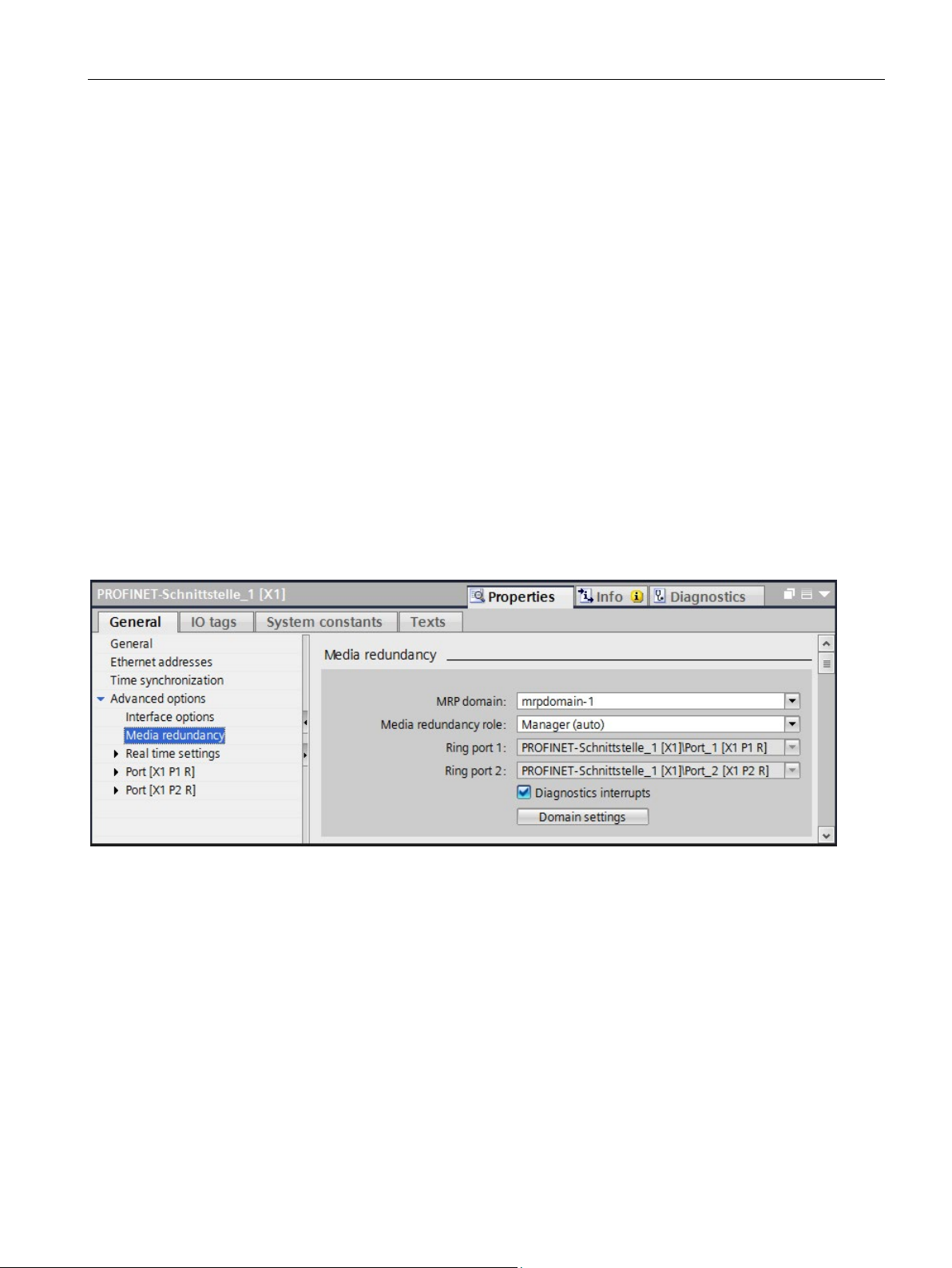
1. In the network view of STEP 7, select PROFINET interface X1 of one of the two CPUs.
2. In the Inspector window, navigate to "Properties" > "General" > "Advanced options" >
"Media redundancy".
Figure 2-6 Media redundancy domain settings
3. Click the "Domain settings" button.
S7-1500R/H redundant system
Getting Started, 10/2018, A5E44910930-AA
25
Page 27
Configuration
2.3 Configuring ET 200SP
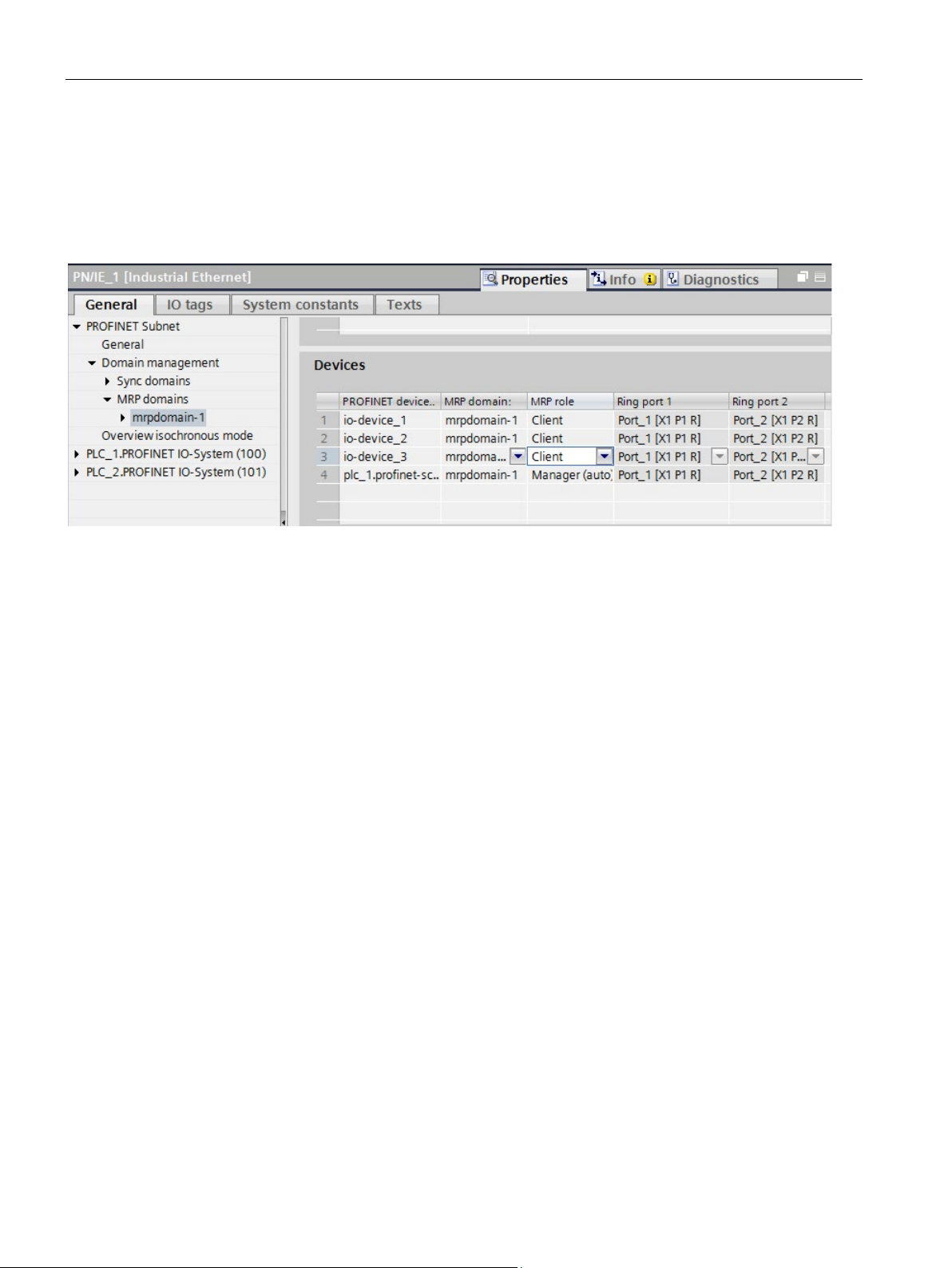
4. In the Inspector window, STEP 7 displays the properties of the MRP domain in which
PROFINET interface X1 of the CPU is located. The CPU has the role "Manager (auto)" in
a redundant system.
5. In the "MRP role" column of the "Devices" table, assign the MRP role "Client" to all other
devices.
Figure 2-7 Assigning MRP roles to the ET 200SP
S7-1500R/H redundant system
26 Getting Started, 10/2018, A5E44910930-AA
Page 28
Configuration
Assign I/O modules to the ET 200SP and set parameters
2.3 Configuring ET 200SP
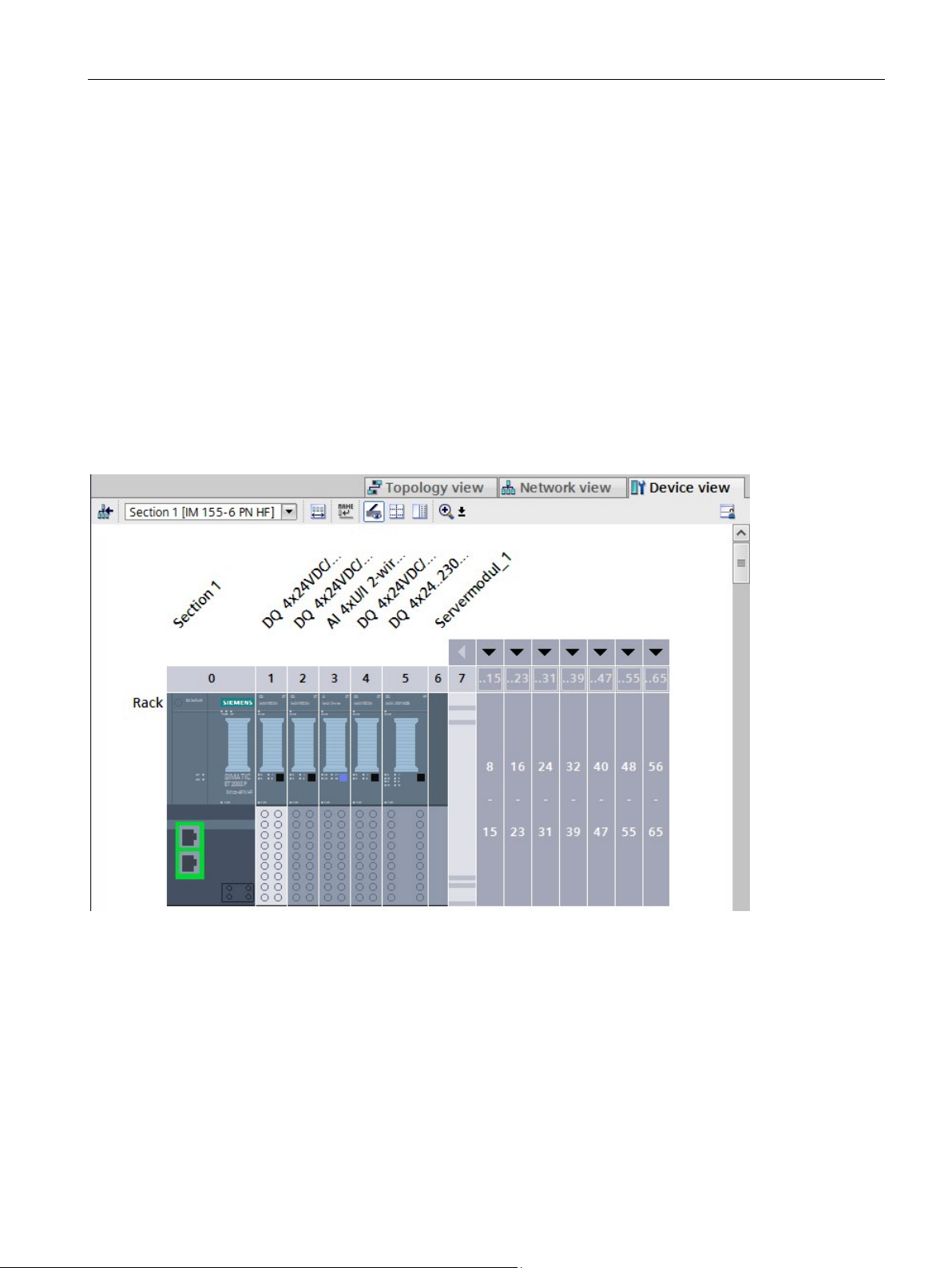
1. Change to the device view of an IM 155-6 PN HF.
2. In the properties of the interface module in the "General" area, assign "Section1" as the
name for tunnel section 1.
3. Select the following modules in succession from the hardware catalog. Assign the
modules to the interface module from slot 1 to 6:
– DQ 4x24VDC/2A ST (for traffic lights)
– DQ 4x24VDC/2A ST (for barrier)
– AI 4xU/I 2-wire ST (for outdoor light, indoor light and air-quality sensors)
– DQ 4x24VDC/2A ST (for fans)
– DQ 4x24..230VAC/2A HF (for tunnel lighting)
– 1 server module (as termination of the configuration)
Figure 2-8 Assigning ET 200SP I/O modules
4. Double-click on the 3rd module DQ 4x24VDC/2A ST in the configuration (for fan).
5. In the module properties "General" > "Potential group", select "Enable new potential
group (light-colored BaseUnit)".
6. Double-click on the module DQ 4x24..230VAC/2A HF (for tunnel lighting).
7. In the module properties "General" > "Potential group", select "Enable new potential
group (light-colored BaseUnit)".
8. Double-click on the module AI 4xU/I 2-wire ST.
S7-1500R/H redundant system
Getting Started, 10/2018, A5E44910930-AA
27
Page 29
Configuration
Result:
2.3 Configuring ET 200SP
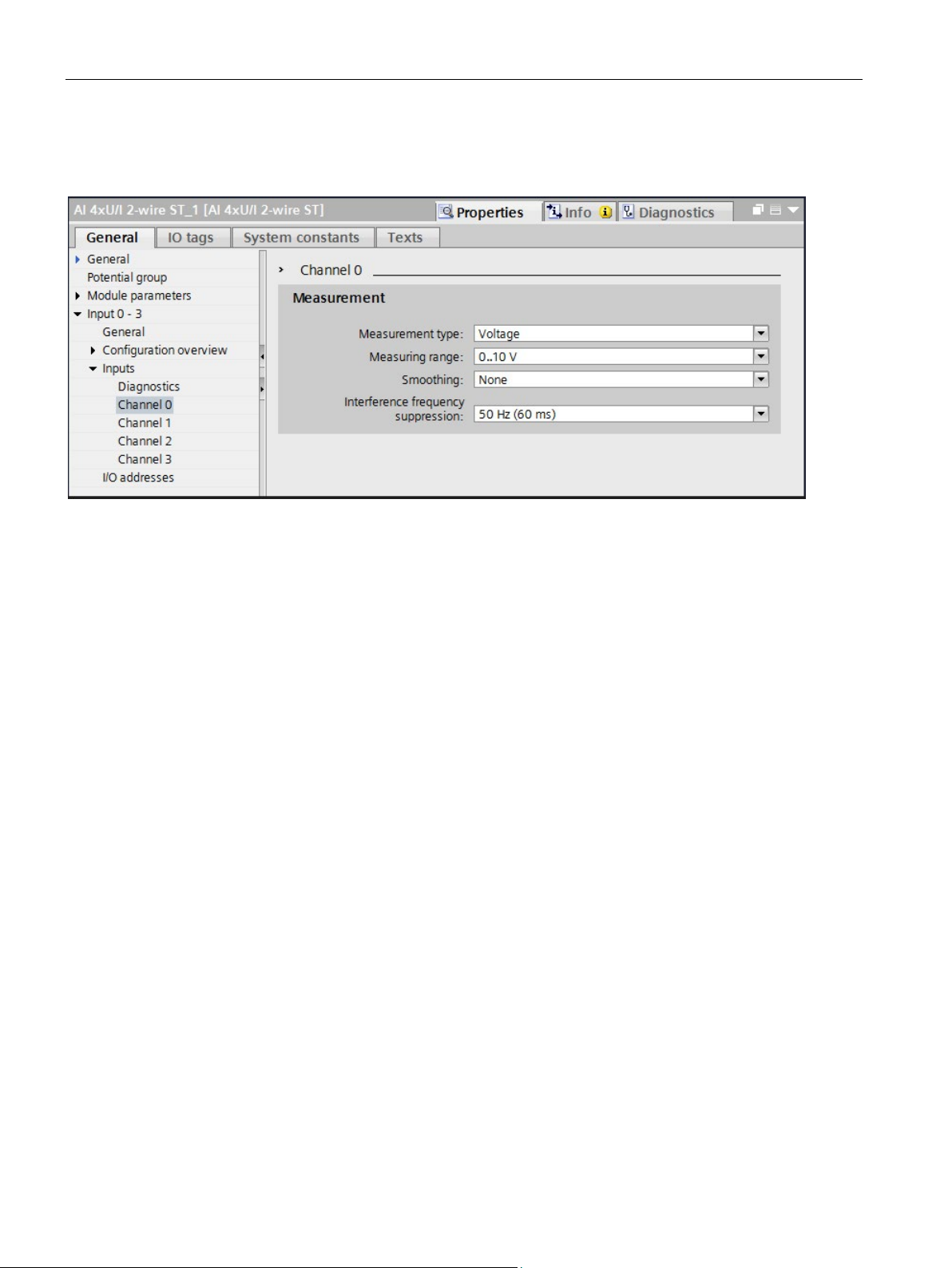
9. In the module properties, set the measurement type "Voltage" and measuring range
"0..10 V" under "Inputs" for channels 0 to 2 in each case.
Figure 2-9 Setting the measurement type and measuring ranges
10.Set the measurement type to "Disabled" for channel 3.
11.For the module DQ 4x24..230VAC/2A HF retain the defaults, in particular the "Phase
angle control - phase angle proportional" mode.
12.Proceed in exactly the same way according to steps 1 to 11 for tunnel section 3. For
tunnel section 2, the two digital output modules DQ 4x24VDC/2A ST for barrier and traffic
lights control are not required.
The ET 200SP I/O modules are fully configured for the tunnel application.
S7-1500R/H redundant system
28 Getting Started, 10/2018, A5E44910930-AA
Page 30
Configuration
Setting the watchdog time
2.3 Configuring ET 200SP
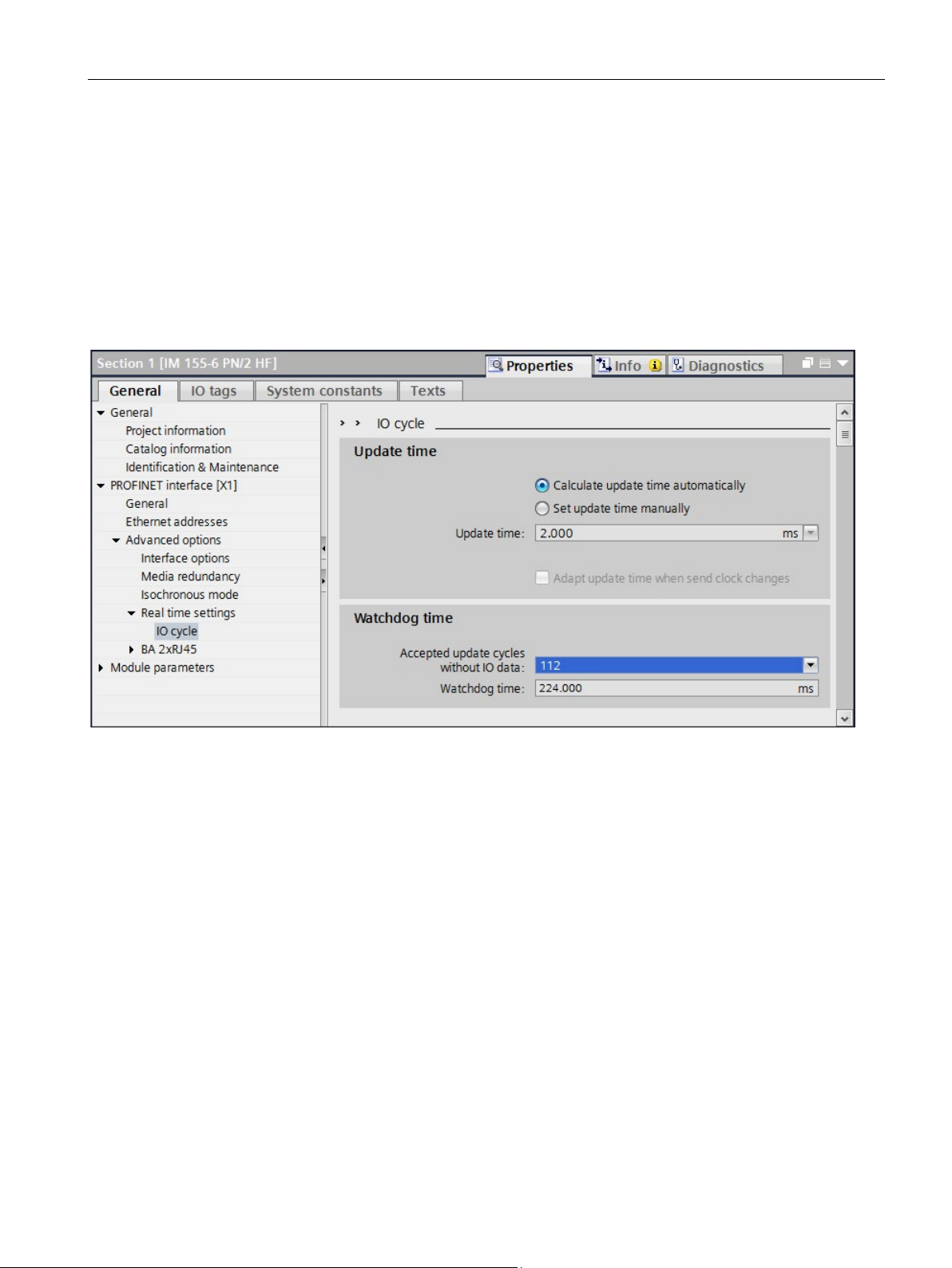
Do not enter the watchdog time directly, but as "Accepted number of update cycles when IO
data is missing". The resulting watchdog time is automatically calculated from the "Accepted
number of update cycles when IO data is missing".
1. Select an interface module IM 155-6 PN HF.
2. Navigate to "Properties" > "Advanced options" > "Real time settings" > "IO cycle" >
"Watchdog monitoring".
3. Set the update cycles for the example to 112 (224 ms).
Figure 2-10 Setting the watchdog time
4. Follow steps 1. to 3. for the other two interface modules IM 155-6 PNHF (tunnel sections
2 and 3).
S7-1500R/H redundant system
Getting Started, 10/2018, A5E44910930-AA
29
Page 31

Configuration
2.4
Configuring HMI devices
Introduction
HMI device wizard
Connection via a device IP address:
Assigning names for HMI devices
2.4 Configuring HMI devices
Assign names for the two HMI devices.
Connect the HMI devices to the redundant system as follows:
● Network the HMI devices with an H-CPU in each case.
● Configure two HMI connections.
● Assign the system IP address of a PROFINET interface of the H-CPU or
● Use the device IP address of the respective PROFINET interface of the two H-CPUs
Recommendation: Configure the HMI devices with the HMI Device Wizard. The HMI device
wizard will guide you through each dialog step by step and help you set up an HMI device.
The HMI device wizard will automatically start when you create a new HMI device in your
project via the project navigation.
When connecting via the device IP address, the HMI device always communicates with the
connected CPU. Communication is independent of the system state. The connected CPU
then synchronizes the data with the other CPU.
Requirements: Each HMI device is connected to a CPU via a separate subnet.
In the example, the TP1900 Comforts communicate in each case via the devices IP address
of the PROFINET interface with the directly connected CPU.
1. Select the left-hand TP1900 Comfort in the network view.
2. Change to the device view.
3. In the properties in the "General" area, assign the name "HMI left".
4. Assign the name "HMI right" for the TP1900 Comfort of the CPU on the right.
S7-1500R/H redundant system
30 Getting Started, 10/2018, A5E44910930-AA
Page 32
Configuration
Setting up HMI connections
Result:
2.4 Configuring HMI devices
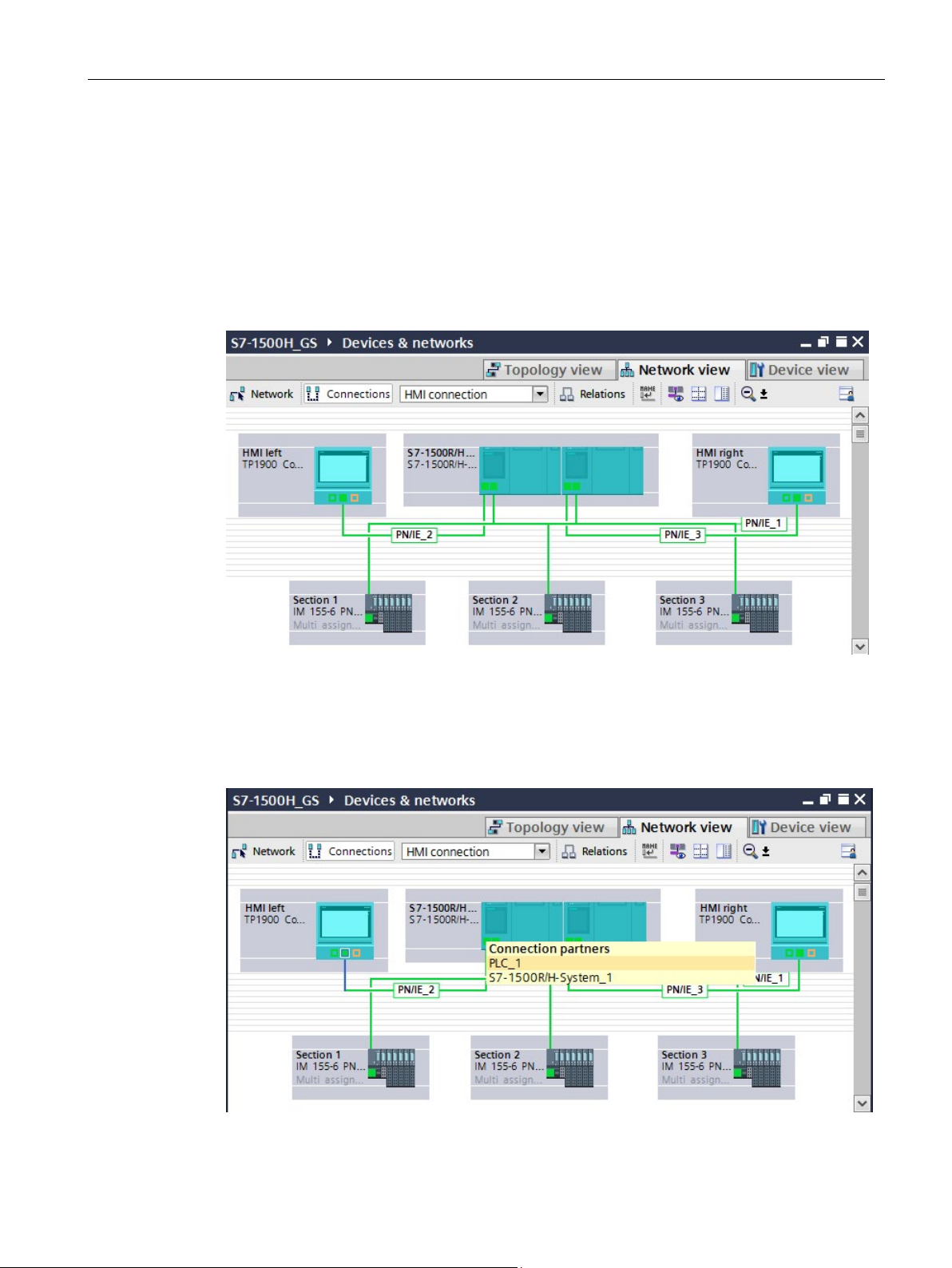
Connect the HMI devices to the CPUs via separate PROFINET subnets.
1. Using drag-and-drop, draw a line between the PROFINET interface X1 of the "HMI left"
and the PROFINET interface X2 of the left-hand CPU.
2. Using drag-and-drop, draw a line between the PROFINET interface X1 of the "HMI right"
and the PROFINET interface X2 of the right-hand CPU.
Figure 2-11 HMI devices networked with CPUs
The HMI devices are networked with the CPUs.
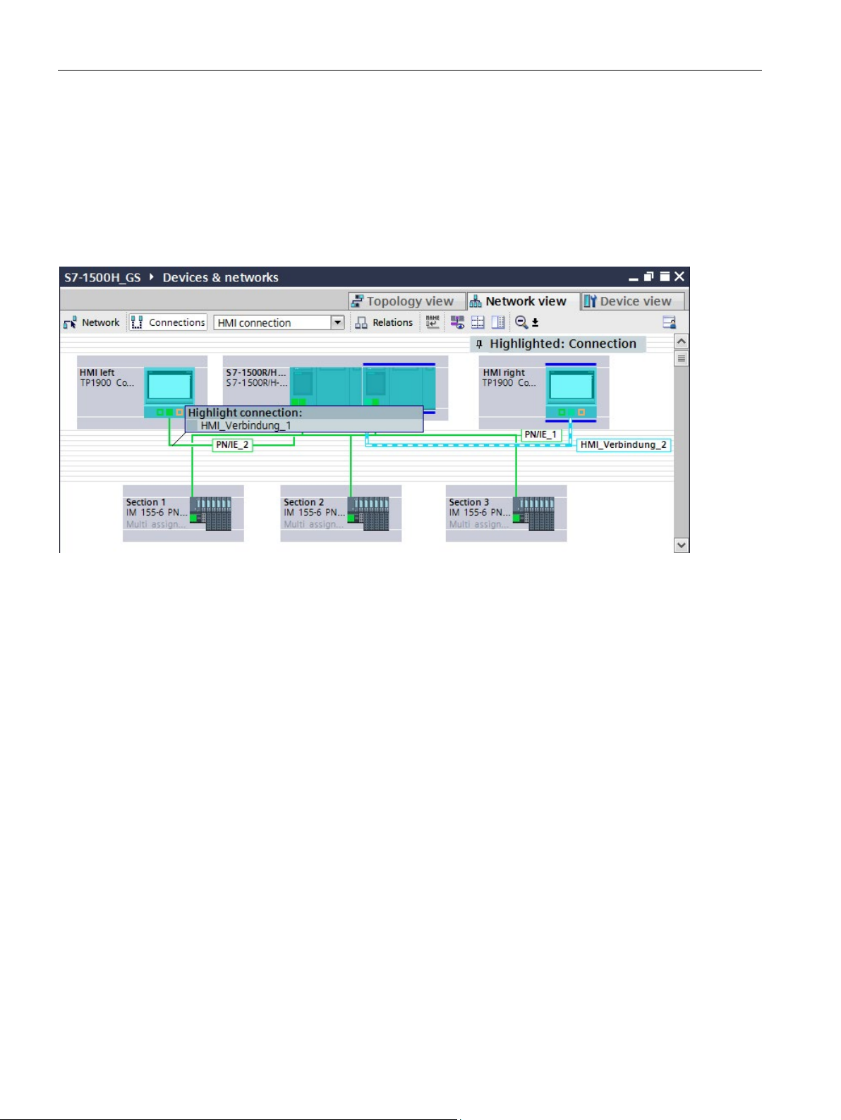
3. In the network view, click on "Connections". This activates connection mode.
4. Using drag-and-drop, draw a line between the networked PROFINET interfaces of "HMI
left" and the left-hand CPU. The "Connection partners" list opens.
Figure 2-12 Assign HMI connection_1 connection partner
S7-1500R/H redundant system
Getting Started, 10/2018, A5E44910930-AA
31
Page 33
Configuration
Result:
2.4 Configuring HMI devices
5. In the "Connection partner" list, select the CPU "PLC_1".
6. Using drag-and-drop, draw a line between the networked PROFINET interfaces of "HMI
right" and the right-hand CPU. The "Connection partners" list opens.
7. In the "Connection partner" list, select the CPU "PLC_2".
You have set up the HMI connections from the HMI devices TP1900 Comfort to the
CPUs.
Figure 2-13 HMI connections set up
S7-1500R/H redundant system
32 Getting Started, 10/2018, A5E44910930-AA
Page 34
Configuration
Setting devices IP addresses for the HMI connections
PROFINET interface
Subnet
IP address
PG/PC
PN/IE1
192.168.0.50
X1 at CPU left
PN/IE1
192.168.0.1
X1 at CPU right
PN/IE1
192.168.0.2
at ET 200SP "section 1"
PN/IE1
192.168.0.3
at ET 200SP "section 2"
PN/IE1
192.168.0.4
at ET 200SP "section 3"
PN/IE1
192.168.0.5
X1 at HMI left
PN/IE_2
192.168.2.2
X1 at HMI right
PN/IE_3
192.168.3.2
2.4 Configuring HMI devices
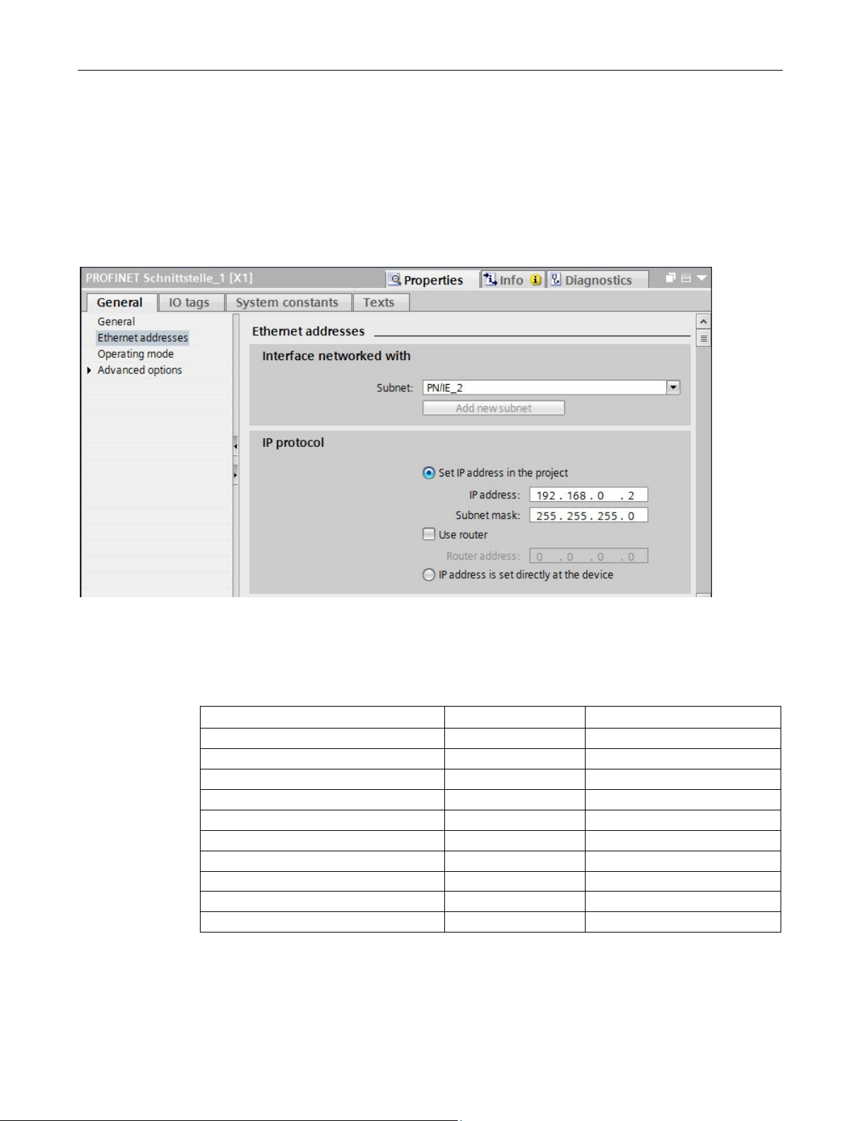
Change the IP addresses of the PROFINET interfaces of the HMI devices and the CPUs for
the PROFINET subnets 2 and 3 (PN/IE_2/3).
1. Select the respective PROFINET interface of the device in the network view.
2. Change the IP address into a valid one in the subnet in the properties in the "Ethernet
addresses" area.
Figure 2-14 IP address for HMI connection to "HMI left" changed
The table below shows all the IP addresses used for the example:
Table 2- 1 IP addresses used in the example
X2 at CPU left PN/IE_2 192.168.2.1
X2 at CPU right PN/IE_3 192.168.3.1
S7-1500R/H redundant system
Getting Started, 10/2018, A5E44910930-AA
33
Page 35

3
Introduction
The example consists of three parts:
● The air quality measurement and fan control in the tunnel
● The traffic light and barrier control
● The lighting control in the tunnel
The following section explains, based on flow diagrams, how the user program works.
Using an HMI screen, you can switch the fans and the lighting in the tunnel from automatic to
manual mode and, if necessary, change limit values.
The user program runs on a CPU 1517H-3 PN with SIMATIC STEP 7 Professional, Version
V15.1.
The executable user program for the example can be found in the annex to the entry on the
Internet (https://support.industry.siemens.com/cs/us/en/view/109757712).
S7-1500R/H redundant system
34 Getting Started, 10/2018, A5E44910930-AA
Page 36

Programming
States in the tunnel
Everything is OK: The air quality sensors measure values within the permissible range:
The air quality sensors measure an increased concentration of pollutants between mean and
maximum value:
The air quality sensors measure a pollutant concentration above the maximum value:
Default tag table
Name
Data type
Address
Description
Air quality measurement and fan control in tunnel section 1
sectionOneAirPollution
Int
IW5
Input word for air quality sensor in section 1
sectionOneVentDrawLeft
Bool
Q2.1
Output bit for anticlockwise rotation fan in section 1
sectionOneVentSlow
Bool
Q2.2
Output bit for low speed fan in section 1
sectionOneVentFast
Bool
Q2.3
Output bit for high speed fan in section 1
Traffic light and cabinet control in tunnel section 1
section1TrafficLightRed
Bool
Q0.0
Output bit for red traffic light in section 1
section1TrafficLightYellow
Bool
Q0.1
Output bit for yellow traffic light in section 1
sectionOneTrafficLightGreen
Bool
Q0.2
Output bit for green traffic light in section 1
sectionOneBarrierUp
Bool
Q1.0
Output bit for barrier in section 1
sectionOneBarrierDown
Bool
Q1.1
Output bit for barrier in section 1
The user program implements 3 states in the tunnel:
● The traffic lights are green.
● The barriers are open.
● The motors for ventilation are in Stop mode, only the flow of air moves the fans.
● The fans immediately run at low level (slow) for at least 30 seconds. The direction of
rotation of the fans depends on the extent of the load in the tunnel section and the
distance to the exit.
● The traffic lights are still green.
● The barriers are still open.
● The fans run immediately at the highest level (fast) for at least 30 seconds. The direction
of rotation of the fans depends on the affected tunnel section and the distance to the exit.
● If the fans did not provide sufficient air within 2 minutes, the tunnel will be blocked:
– The traffic lights are first yellow, then red.
– The barriers close.
The standard tag table contains the PLC tags for the 3 parts of the user program.
sectionOneAirVisibility Int IW3 Input word for turbidity sensor in section 1
sectionOneVentBlowRight Bool Q2.0 Output bit for clockwise rotation fan in section 1
S7-1500R/H redundant system
Getting Started, 10/2018, A5E44910930-AA
35
Page 37

Programming
Name
Data type
Address
Description
Lighting control in tunnel section 1
sectionOneLightEntry
Word
QW21
Output word for brightness of the entry light in section 1
Air quality measurement and fan control in tunnel section 2
sectionTwoAirVisibility
Int
IW21
Input word for turbidity sensor in section 2
sectionTwoAirPollution
Int
IW23
Input word for outdoor light sensor in section 2
sectionTwoVentBlowRight
Bool
Q6.0
Output bit for clockwise rotation fan in section 2
sectionTwoVentDrawLeft
Bool
Q6.1
Output bit for anticlockwise rotation fan in section 2
sectionTwoVentSlow
Bool
Q6.2
Output bit for low speed fan in section 2
sectionTwoVentFast
Bool
Q6.3
Output bit for high speed fan in section 2
Lighting control in tunnel section 2
LightPassage
section 2
tion 2
Air quality measurement and fan control in tunnel section 3
sectionThreeAirVisibility
Int
IW11
Input word for turbidity sensor in section 3
sectionThreeAirPollution
Int
IW13
Input word for air quality sensor in section 3
sectionThreeVentBlowRight
Bool
Q10.0
Output bit for clockwise rotation fan in section 3
sectionThreeVentDrawLeft
Bool
Q10.1
Output bit for anticlockwise rotation fan in section 3
sectionThreeVentSlow
Bool
Q10.2
Output bit for low speed fan in section 3
Traffic light and cabinet control in tunnel section 3
low
Green
sectionThreeBarrierUp
Bool
Q8.0
Output bit for barrier in section 3
sectionThreeBarrierDown
Bool
Q8.1
Output bit for barrier in section 3
Lighting control in tunnel section 3
sectionThreeLuminance
Int
IW9
Input word for outdoor light sensor in section 3
sectionThreeLightPassage
Word
QW29
Output word for brightness of the interior luminance in section 3
sectionThreeLightEntry
Word
QW31
Output word for brightness of the entry light in section 3
sectionOneLuminance Int IW1 Input word for outdoor light sensor in section 1
sectionOneLightPassage Word QW23 Output word for brightness of the interior luminance in section 1
sectionTwoRight-
sectionTwoLeftLightPassage Word QW15 Output word for brightness of the left interior luminance in sec-
sectionThreeVentFast Bool Q10.3 Output bit for high speed fan in section 3
sectionThreeTrafficLightRed Bool Q4.0 Output bit for red traffic light in section 3
sectionThreeTrafficLightYel-
sectionThreeTrafficLight-
Word QW13 Output word for brightness of the right interior luminance in
Bool Q4.1 Output bit for yellow traffic light in section 3
Bool Q4.2 Output bit for green traffic light in section 3
S7-1500R/H redundant system
36 Getting Started, 10/2018, A5E44910930-AA
Page 38
Programming
Flow diagram of the user program OB30
Flow diagram for fan control in FB10
Turbidity measurement and air quality measurement:
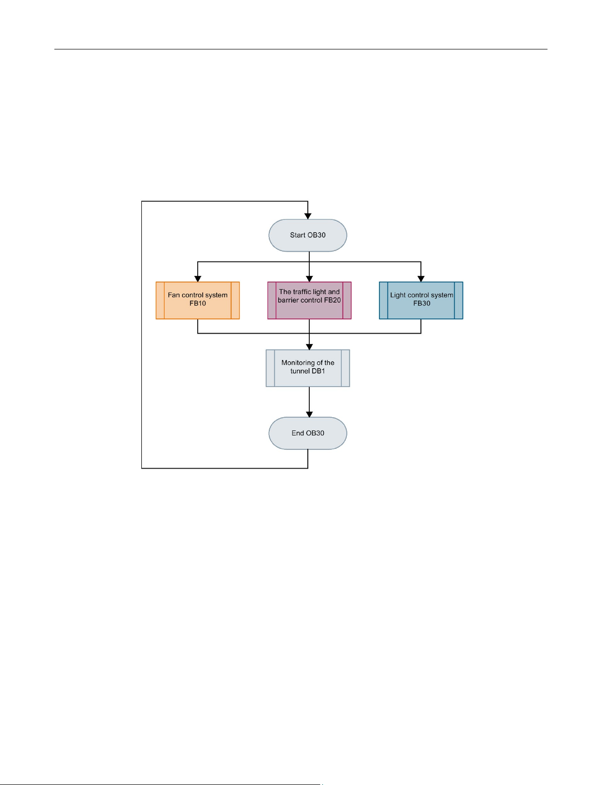
The OB30 contains the user program of the tunnel application with three function blocks for:
● The fan control in the tunnel (FB10)
● The traffic light and barrier control (FB20)
● The lighting control in the tunnel (FB30)
● DB1 contains the HMI tags for the HMI screen.
Figure 3-1 Flow diagram for user program in OB30
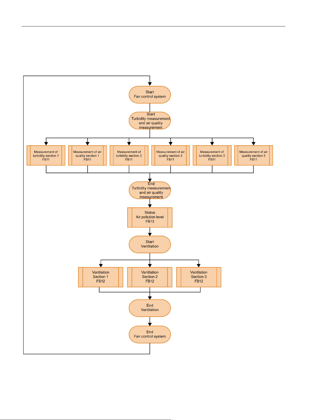
FB10 calls FB11. FB11 reports:
● The status of the air pollution level
● A pollutant concentration above the maximum value, which lasts longer than 2 minutes, to
block the tunnel
S7-1500R/H redundant system
Getting Started, 10/2018, A5E44910930-AA
37
Page 39
Programming
Ventilation in tunnel sections 1, 2 and 3:
FB12 switches the speed and direction of rotation of the fans according to the status of the
air pollution level (FB13) in the tunnel sections.
Figure 3-2 Flow diagram for fan control in FB10
S7-1500R/H redundant system
38 Getting Started, 10/2018, A5E44910930-AA
Page 40
Programming
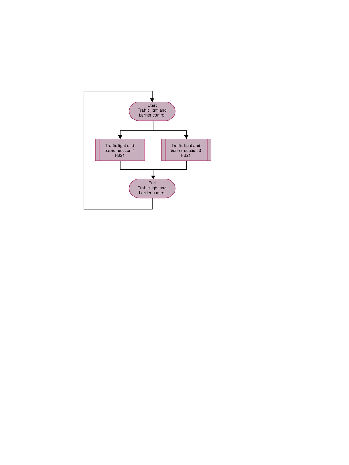
Flow diagram for traffic light and cabinet control FB20
FB20 calls FB21. Depending on the status of the air pollution level (FB13) in the tunnel
sections, both traffic lights are set to green, yellow or red and the barriers are opened or
closed.
Figure 3-3 Flow diagram for traffic light and cabinet control FB20
S7-1500R/H redundant system
Getting Started, 10/2018, A5E44910930-AA
39
Page 41
Programming
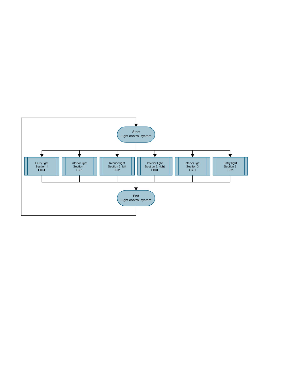
Flow diagram for lighting control in FB30
Control of the entry and interior lights in the tunnel sections.
FB30 calls FB31. The user program controls the turn-on light according to the status of the
outdoor light sensor.
The user program controls the interior lights according to the respective time of day or
enables manual mode:
● Daylight: 8:00 am to 6:00 pm
● Night light: 8:00 pm to 6:00 am
● Twilight light: 6:00 am to 8:00 am and 6:00 pm to 8:00 pm
Figure 3-4 Flow diagram for lighting control in FB30
S7-1500R/H redundant system
40 Getting Started, 10/2018, A5E44910930-AA
Page 42
Programming
Display the status of the tunnel on the panel
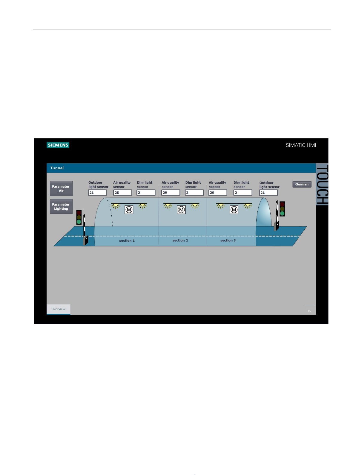
An HMI screen is used to display the status of the tunnel on both Comfort Panels and to set
parameters. The white fields are used to show the current measured values of the sensors.
By double-clicking on the "Air parameters" and "Lighting parameters" buttons, you can
display and change the parameter settings.
By double-clicking on the symbols for lamp and motor, you access the automatic / manual
operating mode.
By double-clicking on a box for the sensors, you access the automatic / manual operating
mode for specifying sensor values.
Figure 3-5 HMI overview screen of tunnel
S7-1500R/H redundant system
Getting Started, 10/2018, A5E44910930-AA
41
Page 43

Programming
Adjustable limits and parameters in the HMI screen
You can use the HMI screen to change the following limit values during user program
runtime:
You can use the HMI screen to change the following limit values in manual operation:
● The limit values for air pollution (carbon monoxide and turbidity) in the tunnel sections
● The light intensity limit value for the outdoor light sensors at the tunnel
● Switch the fans in the tunnel sections to stop / slow / fast
● Change the clockwise / anticlockwise direction of rotation of the fans in the tunnel
sections
● Change the light intensity for the dimmer control of the lighting in the tunnel
● The lamps in the tunnel individually control day, twilight or night mode with different light
intensities
● For test purposes, set the values for the outdoor light, air quality and turbidity sensors
S7-1500R/H redundant system
42 Getting Started, 10/2018, A5E44910930-AA
Page 44
Programming
Limit values for air pollution
If a maximum value is exceeded after 2 minutes:
As soon as a mean value is exceeded:
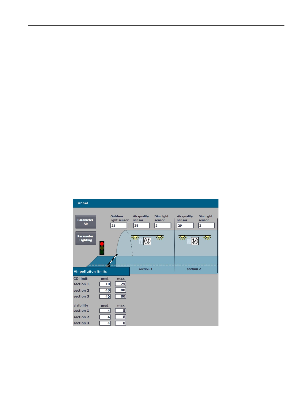
The "Air parameters" button is used to display the air pollution limit values (carbon monoxide
and turbidity) in the tunnel sections.
● The traffic lights are red
● The barriers close
● The fan sucks in / blows out air in the tunnel section at high speed, in the example in the
left direction (tunnel exit)
In the example in the screen, the air quality sensor measures the value 28 in tunnel section
1, the maximum limit value is 25.
In the example in the screen, the turbidity sensor measures the value 2. The value is below
the mean, therefore the view is in the normal range.
● The traffic lights are green
● The barriers remain open
● The fan sucks in / blows out air in the tunnel section at low speed
You can change the mean and maximum value limits for each tunnel section.
Figure 3-6 HMI screen for air pollution limit value
S7-1500R/H redundant system
Getting Started, 10/2018, A5E44910930-AA
43
Page 45
Programming
The light intensity limit value for the exterior light sensors and light intensity
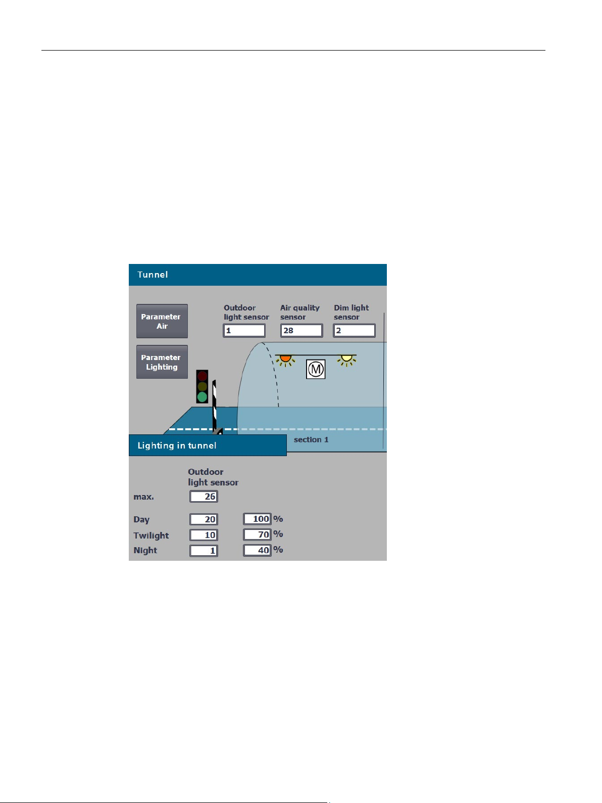
Using the "Lighting parameters" button you display the following:
● The limit value for outdoor light sensors
● The limit values for day / twilight / night light
● The light intensity in the tunnel according to the time of day
The outdoor light sensors on the tunnel control the respective entrance light in the tunnel.
The interior lights are controlled by the time of day.
In the example, the outdoor light sensor measures 1, the night light setting (subdued light) is
thus effective for the entry into the tunnel.
You can change the limit values for the tunnel.
Figure 3-7 HMI screen for light limit value
S7-1500R/H redundant system
44 Getting Started, 10/2018, A5E44910930-AA
Page 46
Programming
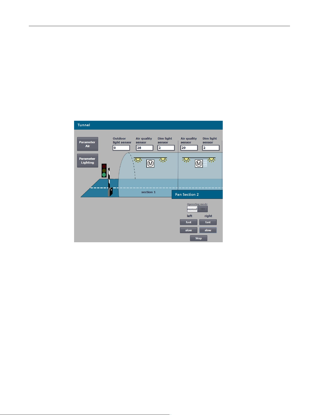
Change manual mode speed and direction of rotation of the fans
By double-clicking on a symbol for a motor, you access the automatic / manual operating
mode for the fan in the corresponding tunnel section.
In the example, the following was set for tunnel section 2:
● Manual operation for the fan
● Low speed (slow)
● Clockwise
The fan blows at slow speed in clockwise direction.
Figure 3-8 HMI screen manual mode fan speed and direction of rotation
S7-1500R/H redundant system
Getting Started, 10/2018, A5E44910930-AA
45
Page 47
Programming
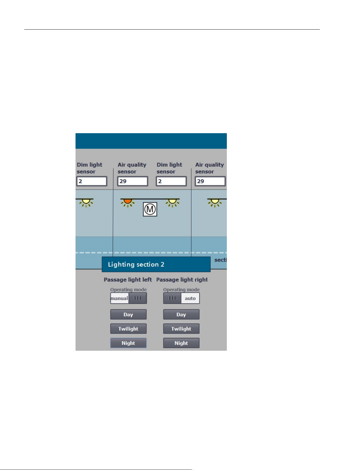
Controlling manual operation of the lamps individually
For maintenance tasks, it may be advisable to manually set the brightness in the tunnel. By
double-clicking on a symbol for a lamp, you access the automatic / manual operating mode
for the lighting in the corresponding tunnel section.
In the example, for the left interior light was set in tunnel section 2:
● Manual mode
● Night light
The lamp emits subdued light.
Figure 3-9 Controlling the HMI screen lamps individually
S7-1500R/H redundant system
46 Getting Started, 10/2018, A5E44910930-AA
Page 48
Programming
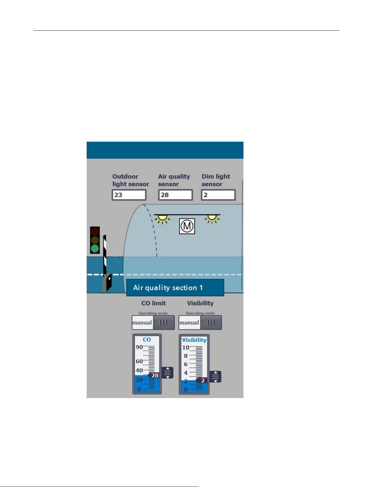
Specifying manual operation sensor values
By specifying the sensor values, you can test the function of the tunnel application. By
double-clicking on a box for the sensors, you access the automatic / manual operating mode.
In the example, the following was set for tunnel section 1:
● Manual operation for setting the CO limit value (air quality sensor)
● CO limit value of 28
● Manual operation for specifying the limit value for the vision (turbidity sensor)
● Value for the vision of 2
Figure 3-10 Specifying HMI screen sensor values
S7-1500R/H redundant system
Getting Started, 10/2018, A5E44910930-AA
47
Page 49

4
Introduction
Inserting SIMATIC memory cards
Requirement:
Procedure:
Switching on load current supply and CPUs
Requirements:
Procedure:
Result
You have configured and programmed the tunnel application. The following sections
describe how to commission the tunnel application.
Further information on commissioning is available in the system manual of Redundant
System S7-1500R/H (https://support.industry.siemens.com/cs/ww/en/view/109754833).
The CPUs only support pre-formatted SIMATIC memory cards. If required, format the
SIMATIC memory cards before using them in the CPU.
1. Open the front cover of the CPU.
2. Ensure that the CPU is either switched off or in STOP mode.
3. Insert the SIMATIC memory card, as shown on the CPU, into the slot for the SIMATIC
memory card.
4. Carefully insert the SIMATIC memory card into the CPU, pushing gently, until the card
clicks into place.
5. Insert the other SIMATIC memory card into the right-hand CPU as described in steps 1 to
4.
Insert a SIMATIC memory card into the left-hand CPU as follows.
The SIMATIC S7-1500R/H redundant system has been installed. The system has been
wired. The SIMATIC memory cards are in the CPUs. The load current supply is connected to
the power supply.
Turn on the load current supply.
:
● The CPUs run a flash test and on completion of system initialization goes to STOP. The
RUN/STOP LEDs on both CPUs are yellow.
● The two CPUs implement pairing. The ERROR LEDs are flashing red. In STEP 7 in the
diagnostic status (Online & diagnostics) of the S7-1500R/H system, check successful
paring. "Paired" is shown in the "Pairing state" field.
S7-1500R/H redundant system
48 Getting Started, 10/2018, A5E44910930-AA
Page 50

Commissioning
Assigning redundancy IDs to CPUs in the configuration
Requirements:
Procedure:
Result
Downloading project data to the primary CPU
Procedure:
Result
Result
Redundant operation is only possible if the two CPUs have different redundancy IDs. The
redundancy IDs can have values of 1 and 2. Both CPUs have redundancy ID 1 in the
configuration as the default:
The redundancy ID is used to assign a project tree to the real CPU in STEP 7. The upper
CPU of the two in the tree always has a redundancy ID of 1. The lower CPU of the two
always has the redundancy ID 2.
Both CPUs are in STOP. There is pairing between the two CPUs.
1. On the CPU display of the right CPU, select the menu item "Overview> Redundancy".
2. Assign the CPU redundancy ID 2.
: The right-hand CPU in the configuration is assigned redundancy ID 2.
In the example, download the project data from the PG/PC to the primary CPU via an online
connection. The project data (all configuration data and the complete user program) can only
be downloaded when a CPU is in STOP operating state.
1. Right-click to select the S7-1500R/H system in the project tree.
2. Select the "Download to device" > "Hardware and software (changes only)" command
from the shortcut menu.
: The "Extended download" dialog window opens.
3. Select the PG/PC interface.
4. Select the interface to which the PG/PC is connected.
5. Click on the "Start search" button.
Result: The "Choose target device" table shows the CPUs in the S7-1500H system. The
primary CPU is already selected.
6. Click "Load".
: The "Load preview" dialog window sets out the key information on the load
process to be run:
7. If the S7-1500R/H system is not in STOP, stop the system. To do so, select "Stop RH
system" in the "Action" column of the drop-down menu.
8. Click the "Download" button to start the download.
The "Results of loading" dialog window displays the results of the loading process.
S7-1500R/H redundant system
Getting Started, 10/2018, A5E44910930-AA
49
Page 51

Commissioning
Starting CPUs after downloading
Requirement:
Procedure:
Result:
Result
Evaluating LEDs and displays at the CPUs
Result
The CPU mode selector is in the RUN position.
1. To start the primary CPU after loading is complete, select "Start module" in the "Action"
column.
2. To complete loading, click "Finish".
3. Switch the backup CPU to the RUN operating state.
1500R/H system switches to redundant mode (system state RUN=Redundant).
The primary CPU switches to the RUN operating state.
: After successful synchronization between the primary and backup CPU, the S7-
If the CPUs are in the "target" system state RUN-Redundant and there are no events,
requirements and errors, then the two CPUs show the following LED screens:
● the RUN/STOP LED lights up green
● the ERROR-LED is off
● the MAINT LED is off
The status information of the CPU is displayed on the display. In the system state RUNRedundant, "RUN-Redundant" is displayed in a green bar on the two CPU displays.
You have fully created and downloaded the configuration and the user program in
accordance with the task of the example.
S7-1500R/H redundant system
50 Getting Started, 10/2018, A5E44910930-AA
Page 52

5
Further information
Topics
Further information
) system manual
sioning of ET 200SP
(https://support.industry.siemens.com/cs/ww/en/view/58649293)
manual
operating instructions
gramming, HMI visualization, diagnostics
function manual
function manual
STEP 7
(https://support.industry.siemens.com/cs/ww/en/view/59192926)
Seiten/Default.aspx)
Below is a collection of links:
● for additional information on the systems and components which were used in the Getting
Started
● to tunnel automation
Table 5- 1 Collection of links
Components, failure scenarios, setup, installation, wiring and commissioning of S7-1500R/H
Components, setup, installation, wiring and commis-
PM 190 W 120/230 V AC load current supply PM 190 W 120/230 V AC load current supply
HMI devices TP1900 Comfort SIMATIC HMI Comfort Panels
SIMATIC STEP 7 Professional: Configuration, pro-
PROFINET at S7-1500R/H, system redundancy S2,
media redundancy (MRP)
HMI communication to S7-1500R/H, System IP address Communication
Diagnostics of S7-1500R/H on the CPU display and in
Siemens tunnel automation on the Internet
Redundant System S7-1500R/H
(https://support.industry.siemens.com/cs/ww/en/view/109754833
System manual ET 200SP Distributed I/O System
(https://support.industry.siemens.com/cs/ww/en/view/68022506)
(https://support.industry.siemens.com/cs/de/en/view/49313233)
In the STEP 7 online help
PROFINET
(https://support.industry.siemens.com/cs/ww/en/view/49948856)
(https://support.industry.siemens.com/cs/ww/en/view/59192925)
Function manual Diagnostics
(https://w3.siemens.com/topics/global/en/tunnelautomatisierung/
S7-1500R/H redundant system
Getting Started, 10/2018, A5E44910930-AA
51
 Loading...