

Page 1
S7-1500 Motion Control V13 Update 3
___________________
___________________
___________________
___________________
___________________
___________________
___________________
___________________
___________________
___________________
___________________
___________________
___________________
SIMATIC
S7-1500
S7-1500 Motion Control V13
Update 3
Function Manual
07/2014
A5E03879256
Preface
Guide to documentation
S7-1500 / ET 200MP
1
Introduction
2
Basics
3
Guidelines
4
Using versions
5
Configuring
6
Programming
7
Downloading to CPU
8
Commissioning
9
Diagnostics
10
Instructions
11
Appendix
A
-AC
Page 2
Siemens AG
Industry Sector
Postfach 48 48
90026 NÜRNBERG
GERMANY
A5E03879256-AC
Ⓟ
Copyright © Siemens AG 2013 - 2014.
All rights reserved
Legal information
Warning notice system
DANGER
indicates that death or severe personal injury will result if proper precautions are not taken.
WARNING
indicates that death or severe personal injury may result if proper precautions are not taken.
CAUTION
indicates that minor personal injury can result if proper precautions are not taken.
NOTICE
indicates that property damage can result if proper precautions are not taken.
Qualified Personnel
personnel qualified
Proper use of Siemens products
WARNING
Siemens products may only be used for the applications described in the catalog and in the relevant technical
Trademarks
Disclaimer of Liability
This manual contains notices you have to observe in order to ensure your personal safety, as well as to prevent
damage to property. The notices referring to your personal safety are highlighted in the manual by a safety alert
symbol, notices referring only to property damage have no safety alert symbol. These notices shown below are
graded according to the degree of danger.
If more than one degree of danger is present, the warning notice representing the highest degree of danger will
be used. A notice warning of injury to persons with a safety alert symbol may also include a warning relating to
property damage.
The product/system described in this documentation may be operated only by
task in accordance with the relevant documentation, in particular its warning notices and safety instructions.
Qualified personnel are those who, based on their training and experience, are capable of identifying risks and
avoiding potential hazards when working with these products/systems.
for the specific
Note the following:
documentation. If products and components from other manufacturers are used, these must be recommended
or approved by Siemens. Proper transport, storage, installation, assembly, commissioning, operation and
maintenance are required to ensure that the products operate safely and without any problems. The permissible
ambient conditions must be complied with. The information in the relevant documentation must be observed.
All names identified by ® are registered trademarks of Siemens AG. The remaining trademarks in this publication
may be trademarks whose use by third parties for their own purposes could violate the rights of the owner.
We have reviewed the contents of this publication to ensure consistency with the hardware and software
described. Since variance cannot be precluded entirely, we cannot guarantee full consistency. However, the
information in this publication is reviewed regularly and any necessary corrections are included in subsequent
editions.
07/2014 Subject to change
Page 3

Preface
Purpose of the documentation
Required basic knowledge
Validity of the documentation
Conventions
Note
A note contains important information about the product described in the documentation,
about the handling of the product, and about sections in this documentation demanding your
particular
Further support
This documentation provides important information that you need to configure and
commission the integrated Motion Control functionality of the S7-1500 Automation systems.
In order to understand this documentation, the following knowledge is required:
● General knowledge in the field of automation
● General knowledge in the field of drive engineering and motion control
This documentation is valid for the S7-1500 product range.
● For the path settings in the project navigation it is presumed that the "Technology objects"
object is opened in the CPU subtree. The "Technology object" placeholder represents the
name of the technology object.
Example: "Technology object > Configuration > Basic parameters".
● The <TO> placeholder represents the name set in tags for the respective technology
object.
Example: <TO>.Actor.Type
● This documentation contains pictures of the devices described. The pictures may differ in
minor details from the devices supplied.
You should also observe the notes that are marked as follows:
attention.
● The range of technical documentation for the individual SIMATIC products and systems is
available on the Internet (http://www.siemens.com/simatic-tech-doku-portal).
● The online catalog and the online ordering system is available on the Internet
(http://mall.automation.siemens.com).
S7-1500 Motion Control V13 Update 3
Function Manual, 07/2014, A5E03879256-AC
3
Page 4

Preface
Security information
Siemens provides products and solutions with industrial security functions that support the
secure operation of plants, solutions, machines, equipment and/or networks. They are
important components in a holistic industrial security concept. With this in mind, Siemens’
products and solutions undergo continuous development. Siemens recommends strongly
that you regularly check for product updates.
For the secure operation of Siemens products and solutions, it is necessary to take suitable
preventive action (e.g. cell protection concept) and integrate each component into a holistic,
state-of-the-art industrial security concept. Third-party products that may be in use should
also be considered. You can find more information about industrial security on the Internet
(http://www.siemens.com/industrialsecurity).
To stay informed about product updates as they occur, sign up for a product-specific
newsletter. You can find more information on the Internet
(http://support.automation.siemens.com).
S7-1500 Motion Control V13 Update 3
4 Function Manual, 07/2014, A5E03879256-AC
Page 5

Table of contents
Preface ...................................................................................................................................................... 3
1 Guide to documentation S7-1500 / ET 200MP......................................................................................... 13
2 Introduction .............................................................................................................................................. 15
3 Basics ...................................................................................................................................................... 20
2.1 Integrated Motion Control Functionality of the CPU S7-1500 ................................................ 15
2.2 Principle of operation of S7-1500 Motion Control ................................................................... 16
3.1 Functions ................................................................................................................................ 20
3.2 Scale ....................................................................................................................................... 21
3.3 Speed-controlled axis technology object ................................................................................ 21
3.4 Positioning axis technology object .......................................................................................... 22
3.5 Synchronous axis technology object ...................................................................................... 23
3.6 External encoder technology object ........................................................................................ 25
3.7 Axis types ................................................................................................................................ 26
3.8 Modulo setting ......................................................................................................................... 26
3.9 Units of measure ..................................................................................................................... 27
3.10 Drive and encoder connection ................................................................................................ 28
3.10.1 Brief description ...................................................................................................................... 28
3.10.2 Frames .................................................................................................................................... 29
3.10.3 Setting reference values ......................................................................................................... 31
3.10.4 Tags ........................................................................................................................................ 32
3.11 Safety functions in the drive .................................................................................................... 33
3.11.1 Brief description ...................................................................................................................... 33
3.11.2 Safe Torque Off (STO) ........................................................................................................... 33
3.11.3 Safe Stop 1 (SS1) ................................................................................................................... 34
3.11.4 Safe Stop 2 (SS2) ................................................................................................................... 34
3.12 Actual values ........................................................................................................................... 35
3.12.1 Brief description ...................................................................................................................... 35
3.12.2 Incremental actual value ......................................................................................................... 35
3.12.3 Absolute actual value .............................................................................................................. 35
3.12.4 Tags ........................................................................................................................................ 36
3.13 Mechanics ............................................................................................................................... 37
3.13.1 Brief description ...................................................................................................................... 37
3.13.2 Tags ........................................................................................................................................ 38
3.14 Homing .................................................................................................................................... 39
3.14.1 Brief description ...................................................................................................................... 39
3.14.2 Terms ...................................................................................................................................... 40
3.14.3 Homing mode .......................................................................................................................... 41
S7-1500 Motion Control V13 Update 3
Function Manual, 07/2014, A5E03879256-AC
5
Page 6

Table of contents
4 Guidelines ................................................................................................................................................ 85
5 Using versions ......................................................................................................................................... 86
3.14.4 Active homing with zero mark and proximity switch .............................................................. 43
3.14.5 Active homing with zero mark ................................................................................................ 46
3.14.6 Active homing with digital input .............................................................................................. 48
3.14.7 Passive homing with zero mark and proximity switch ............................................................ 50
3.14.8 Passive homing with zero mark ............................................................................................. 52
3.14.9 Passive homing with digital input ........................................................................................... 54
3.14.10 Direction reversal at the hardware limit switch (reversing cam) ............................................ 55
3.14.11 Direct homing ......................................................................................................................... 56
3.14.12 Absolute value adjustment ..................................................................................................... 56
3.14.13 Resetting the "Homed" status ................................................................................................ 57
3.14.14 Tags ....................................................................................................................................... 58
3.15 Control .................................................................................................................................... 59
3.15.1 Brief description ..................................................................................................................... 59
3.15.2 Control structure..................................................................................................................... 60
3.15.3 Tags ....................................................................................................................................... 61
3.16 Position-related monitoring .................................................................................................... 61
3.16.1 Brief description ..................................................................................................................... 61
3.16.2 Positioning monitoring ............................................................................................................ 62
3.16.3 Following error monitoring ..................................................................................................... 63
3.16.4 Tags ....................................................................................................................................... 64
3.17 Traversing range limitation ..................................................................................................... 65
3.17.1 Brief description ..................................................................................................................... 65
3.17.2 Hardware limit switches ......................................................................................................... 65
3.17.3 Software limit switch .............................................................................................................. 67
3.17.4 Tags ....................................................................................................................................... 68
3.18 Motion control and limits for dynamics ................................................................................... 69
3.18.1 Brief description ..................................................................................................................... 69
3.18.2 Velocity profile ........................................................................................................................ 70
3.18.3 Emergency stop deceleration ................................................................................................ 71
3.18.4 Tags ....................................................................................................................................... 72
3.19 Synchronous operation .......................................................................................................... 73
3.19.1 Brief description ..................................................................................................................... 73
3.19.2 Relative gearing ..................................................................................................................... 74
3.19.3 Master value coupling ............................................................................................................ 76
3.19.4 Tags ....................................................................................................................................... 77
3.20 O
perational sequence ............................................................................................................ 78
3.20.1 Organization Blocks for Motion Control ................................................................................. 78
3.20.2 Process image partition "OB Servo PIP" ............................................................................... 80
3.20.3 Operational Sequence and Timeouts .................................................................................... 80
3.20.4 Operating modes ................................................................................................................... 83
4.1 Guidelines on use of motion control....................................................................................... 85
5.1 Overview of versions .............................................................................................................. 86
5.2 Changing a technology version .............................................................................................. 89
S7-1500 Motion Control V13 Update 3
6 Function Manual, 07/2014, A5E03879256-AC
Page 7

Table of contents
6 Configuring .............................................................................................................................................. 91
6.1 Adding and configuring drives in the device configuration ..................................................... 91
6.1.1 Add and configure PROFINET IO drives ................................................................................ 91
6.1.2 Add and configure PROFIBUS DP drives............................................................................... 94
6.1.3 Adding and configuring drives with analog connections ......................................................... 96
6.2 Add technology object ............................................................................................................ 99
6.3 Working with the configuration editor .................................................................................... 100
6.4 Compare values .................................................................................................................... 101
6.5 Configuring the Speed-Control Axis technology object ........................................................ 102
6.5.1 Configuration - Basic Parameters ......................................................................................... 102
6.5.2 Hardware interface ................................................................................................................ 102
6.5.2.1 Configuration - Drive ............................................................................................................. 102
6.5.2.2 Configuration - Data exchange ............................................................................................. 104
6.5.3 Extended Parameters ........................................................................................................... 105
6.5.3.1 Configuration - Mechanics .................................................................................................... 105
6.5.3.2 Configuration - Dynamic limits .............................................................................................. 105
6.5.3.3 Configuration - Dynamic Defaults ......................................................................................... 107
6.5.3.4 Configuration - Emergency stop ........................................................................................... 109
6.6 Configuring the positioning axis/synchronous axis technology object .................................. 110
6.6.1 Configuration - Basic Parameters ......................................................................................... 110
6.6.2 Hardware interface ................................................................................................................ 111
6.6.2.1 Configuration - Drive ............................................................................................................. 111
6.6.2.2 Configuration - Encoder ........................................................................................................ 113
6.6.2.3 Configuration - Data exchange ............................................................................................. 114
6.6.3 Configuration - master value interconnections (synchronous axis only) .............................. 124
6.6.4 Extended Parameters ........................................................................................................... 125
6.6.4.1 Configuration - Mechanics .................................................................................................... 125
6.6.4.2 Configuration - Position monitoring ....................................................................................... 129
6.6.4.3 Configuration - Dynamic limits .............................................................................................. 130
6.6.4.4 Configuration - Dynamic Defaults ......................................................................................... 132
6.6.4.5 Configuration - Emergency stop ........................................................................................... 134
6.6.4.6 Homing .................................................................................................................................. 135
6.6.4.7 Position monitoring ............................................................................................................... 144
6.6.4.8 Configuration - Control loop .................................................................................................. 146
6.7 Configuring the External Encoder technology object
.7.1 Configuration - Basic Parameters ......................................................................................... 147
6
............................................................ 147
6.7.2 Hardware interface ................................................................................................................ 148
6.7.2.1 Configuration - Encoder ........................................................................................................ 148
6.7.2.2 Configuration - Data exchange ............................................................................................. 149
6.7.3 Extended Parameters ........................................................................................................... 153
6.7.3.1 Configuration - Mechanics .................................................................................................... 153
6.7.3.2 Homing .................................................................................................................................. 155
6.8 Parameter view ..................................................................................................................... 159
6.8.1 Introduction to the parameter view ....................................................................................... 159
6.8.2 Structure of the parameter view ............................................................................................ 161
6.8.2.1 Toolbar .................................................................................................................................. 161
6.8.2.2 Navigation ............................................................................................................................. 161
6.8.2.3 Parameter table .................................................................................................................... 162
S7-1500 Motion Control V13 Update 3
Function Manual, 07/2014, A5E03879256-AC
7
Page 8

Table of contents
7 Programming ......................................................................................................................................... 172
8 Downloading to CPU ............................................................................................................................. 198
9 Commissioning ...................................................................................................................................... 199
6.8.3 Opening the parameter view ................................................................................................ 163
6.8.4 Working with the parameter view ......................................................................................... 164
6.8.4.1 Overview .............................................................................................................................. 164
6.8.4.2 Filtering the parameter table ................................................................................................ 164
6.8.4.3 Sorting the parameter table ................................................................................................. 165
6.8.4.4 Transferring parameter data to other editors ....................................................................... 165
6.8.4.5 Indicating errors ................................................................................................................... 166
6.8.4.6 Editing start values in the project ......................................................................................... 166
6.8.4.7 Monitoring values online in the parameter view ................................................................... 168
6.8.4.8 Modifying values .................................................................................................................. 169
6.8.4.9 Comparing values ................................................................................................................ 170
7.1 Introduction .......................................................................................................................... 172
7.2 Technology data block ......................................................................................................... 172
7.2.1 Introduction .......................................................................................................................... 172
7.2.2 Evaluating the technology data block .................................................................................. 173
7.2.3 Evaluate StatusWord, ErrorWord and WarningWord .......................................................... 175
7.2.4 Change restart-relevant data ............................................................................................... 177
7.3 Motion Control instructions .................................................................................................. 178
7.3.1 Motion Control instruction parameters ................................................................................. 178
7.3.2 Add Motion Control instructions ........................................................................................... 181
7.4 Starting Motion Control jobs ................................................................................................. 183
7.5 Tracking active jobs ............................................................................................................. 184
7.5.1 Introduction .......................................................................................................................... 184
7.5.2 Motion Control instructions with "Done" parameter ............................................................. 185
7.5.3 Motion Control instructions without "Done" parameter ........................................................ 189
7.5.4 Motion Control instruction "MC_MoveJog" .......................................................................... 193
7.6 Ending Motion Control jobs .................................................................................................. 196
7.7 Restart of technology objects ............................................................................................... 197
9.1 Introduction .......................................................................................................................... 199
9.2 Commissioning guidelines ................................................................................................... 199
9.3 Axis control panel ................................................................................................................. 202
9.3.1 Function and structure of the axis control panel .................................................................. 202
9.3.2 Using the axis control panel ................................................................................................. 206
9.4 Optimization ......................................................................................................................... 207
9.4.1 Function and structure of the optimization ........................................................................... 207
9.4.2 Optimize position controller .................................................................................................. 210
9.5 Simulation mode .................................................................................................................. 213
S7-1500 Motion Control V13 Update 3
8 Function Manual, 07/2014, A5E03879256-AC
Page 9

Table of contents
10 Diagnostics ............................................................................................................................................ 214
11 Instructions ............................................................................................................................................ 234
10.1 Introduction ........................................................................................................................... 214
10.2 Diagnostic concept ................................................................................................................ 214
10.3 Technology alarms ................................................................................................................ 215
10.4 Errors in Motion Control instructions ..................................................................................... 219
10.5 Speed-controlled axis technology object .............................................................................. 220
10.5.1 Status and error bits .............................................................................................................. 220
10.5.2 Motion status ......................................................................................................................... 223
10.5.3 PROFIdrive frame ................................................................................................................. 224
10.6 Positioning axis/synchronous axis technology object ........................................................... 225
10.6.1 Status and error bits .............................................................................................................. 225
10.6.2 Motion status ......................................................................................................................... 229
10.6.3 PROFIdrive frame ................................................................................................................. 230
10.7 External encoder technology object ...................................................................................... 231
10.7.1 Status and error bits .............................................................................................................. 231
10.7.2 Motion status ......................................................................................................................... 232
10.7.3 PROFIdrive frame ................................................................................................................. 233
11.1 S7-1500 Motion Control V2 .................................................................................................. 234
11.1.1 MC_Power ............................................................................................................................ 234
11.1.1.1 MC_Power: Enable, disable technology objects V2 ............................................................. 234
11.1.1.2 MC_Power: Function chart V2 .............................................................................................. 238
11.1.2 MC_Home ............................................................................................................................. 239
11.1.2.1 MC_Home: Home technology objects, set home position V2 .............................................. 239
11.1.3 MC_MoveJog ........................................................................................................................ 244
11.1.3.1 MC_MoveJog: Move axes in jog mode V2 ........................................................................... 244
11.1.3.2 MC_MoveJog: Function chart V2 .......................................................................................... 248
11.1.4 MC_MoveVelocity ................................................................................................................. 249
11.1.4.1 MC_MoveVelocity: Move axes at predefined velocity V2 ..................................................... 249
11.1.4.2 MC_MoveVelocity: Function chart V2 ................................................................................... 254
11.1.5 MC_MoveRelative ................................................................................................................. 255
11.1.5.1 MC_MoveRelative: Relative positioning of axes V2 ............................................................. 255
11.1.5.2 MC_MoveRelative: Function chart V2 .................................................................................. 259
11.1.6 MC_MoveAbsolute ................................................................................................................ 260
11.1.6.1 MC_MoveAbsolute: Absolute positioning of axes V2 ........................................................... 260
11.1.6.2 MC_MoveAbsolute: Function chart V2 ................................................................................. 264
11.1.7 MC_MoveSuperimposed ...................................................................................................... 265
11.1.7.1 MC_MoveSuperimposed: Superimposed positioning of axes V2 ......................................... 265
11.1.7.2 MC_MoveSuperimposed: Function chart V2 ........................................................................ 269
11.1.8 MC_GearIn ............................................................................................................................ 270
11.1.8.1 MC_GearIn: Start gearing V2 ............................................................................................... 270
11.1.8.2 MC_GearIn: Function chart V2 ............................................................................................. 274
11.1.9 MC_Halt ................................................................................................................................ 275
11.1.9.1 MC_Halt: Stop axes V2 ......................................................................................................... 275
11.1.9.2 MC_Halt: Function chart V2 .................................................................................................. 278
11.1.10 MC_Reset ............................................................................................................................. 279
11.1.10.1 MC_Reset: Acknowledge alarms, restart technology objects V2 ......................................... 279
S7-1500 Motion Control V13 Update 3
Function Manual, 07/2014, A5E03879256-AC
9
Page 10

Table of contents
A Appendix ................................................................................................................................................ 321
11.2 S7-1500 Motion Control V1 .................................................................................................. 282
11.2.1 MC_Power ............................................................................................................................ 282
11.2.1.1 MC_Power: Enable, disable technology objects V1 ............................................................ 282
11.2.1.2 MC_Power: Function chart V1 ............................................................................................. 286
11.2.2 MC_Home ............................................................................................................................ 287
11.2.2.1 MC_Home: Home technology objects, set home position V1 .............................................. 287
11.2.3 MC_MoveJog ....................................................................................................................... 292
11.2.3.1 MC_MoveJog: Move axes in jog mode V1 .......................................................................... 292
11.2.3.2 MC_MoveJog: Function chart V1 ......................................................................................... 296
11.2.4 MC_MoveVelocity ................................................................................................................ 297
11.2.4.1 MC_MoveVelocity: Move axes at predefined specified velocity V1 ..................................... 297
11.2.4.2 MC_MoveVelocity: Function chart V1 .................................................................................. 302
11.2.5 MC_MoveRelative ................................................................................................................ 303
11.2.5.1 MC_MoveRelative: Relative positioning of axes V1 ............................................................ 303
11.2.5.2 MC_MoveRelative: Function chart V1 ................................................................................. 307
11.2.6 MC_MoveAbsolute ............................................................................................................... 308
11.2.6.1 MC_MoveAbsolute: Absolute positioning of axes V1 .......................................................... 308
11.2.6.2 MC_MoveAbsolute: Function chart V1 ................................................................................ 312
11.2.7 MC_Halt ............................................................................................................................... 313
11.2.7.1 MC_Halt: Stop axes V1 ........................................................................................................ 313
11.2.7.2 MC_Halt: Function chart V1 ................................................................................................. 317
11.2.8 MC_Reset ............................................................................................................................ 318
11.2.8.1 MC_Reset: Acknowledge alarms, restart technology objects V1 ........................................ 318
A.1 Tags of the technology object SpeedAxis ............................................................................ 321
A.1.1 Legend ................................................................................................................................. 321
A.1.2 Actual values and setpoints (speed axis) ............................................................................ 321
A.1.3 Variable simulation (speed axis) .......................................................................................... 322
A.1.4 Actor tags (speed axis) ........................................................................................................ 322
A.1.5 LoadGear tags (speed axis) ................................................................................................. 323
A.1.6 DynamicLimits tags (speed axis) ......................................................................................... 324
A.1.7 DynamicDefaults tags (speed axis) ..................................................................................... 324
A.1.8 Override tags (speed axis) ................................................................................................... 325
A.1.9 StatusDrive tags (speed axis) .............................................................................................. 325
A.1.10 StatusWord tag (speed axis) ................................................................................................ 326
A.1.11 ErrorWord tag (speed axis) .................................................................................................. 328
A.1.12 ErrorDetail tags (speed axis) ............................................................................................... 329
A.1.13 WarningWord tag (speed axis) ............................................................................................ 330
A.1.14 ControlPanel tags (speed axis) ............................................................................................ 331
A.1.15 InternalToTrace tags (speed axis) ....................................................................................... 332
A.2 Tags of the positioning axis/synchronous axis technology object ....................................... 332
A.2.1 Legend ................................................................................................................................. 332
A.2.2 Actual values and setpoints (positioning axis/synchronous axis) ........................................ 333
A.2.3 Simulation tag (positioning axis / synchronous axis) ........................................................... 333
A.2.4 Actor tags (positioning axis/synchronous axis) .................................................................... 334
A.2.5 Sensor[n] tags (positioning axis/synchronous axis) ............................................................. 336
A.2.6 LoadGear tags (positioning axis/synchronous axis) ............................................................ 338
A.2.7 Mechanics tags (positioning axis/synchronous axis) ........................................................... 338
A.2.8 Properties tags (positioning axis/synchronous axis) ............................................................ 338
A.2.9 Modulo tags (positioning axis/synchronous axis) ................................................................ 339
A.2.10 DynamicLimits tags (positioning axis/synchronous axis) ..................................................... 339
S7-1500 Motion Control V13 Update 3
10 Function Manual, 07/2014, A5E03879256-AC
Page 11

Table of contents
A.2.11 DynamicDefaults tags (positioning axis/synchronous axis) .................................................. 340
A.2.12 PositionLimits_SW tags (positioning axis/synchronous axis) ............................................... 340
A.2.13 PositionLimits_HW tags (positioning axis/synchronous axis) ............................................... 341
A.2.14 Homing tags (positioning axis/synchronous axis) ................................................................. 342
A.2.15 Override tags (positioning axis/synchronous axis) ............................................................... 343
A.2.16 PositionControl tags (positioning axis/synchronous axis) ..................................................... 344
A.2.17 FollowingError tags (positioning axis/synchronous axis) ...................................................... 345
A.2.18 PositionMonitoring tags (positioning axis/synchronous axis) ............................................... 346
A.2.19 StandstillSignal tags (positioning axis/synchronous axis) .................................................... 347
A.2.20 StatusPositioning tags (positioning axis/synchronous axis) ................................................. 347
A.2.21 StatusDrive tags (positioning axis/synchronous axis) .......................................................... 348
A.2.22 StatusSensor[n] tags (positioning axis/synchronous axis) ................................................... 349
A.2.23 StatusSynchronizedMotion tags (synchronous axis) ............................................................ 350
A.2.24 StatusWord tag (positioning axis/synchronous axis) ............................................................ 351
A.2.25 ErrorWord tag (positioning axis/synchronous axis) .............................................................. 353
A.2.26 ErrorDetail tags (positioning axis/synchronous axis) ............................................................ 355
A.2.27 WarningWord tag (positioning axis/synchronous axis) ......................................................... 356
A.2.28 ControlPanel tags (positioning axis/synchronous axis) ........................................................ 357
A.2.29 InternalToTrace tags (positioning axis/synchronous axis) .................................................... 358
A.3 Tags of the technology object external encoder ................................................................... 358
A.3.1 Legend .................................................................................................................................. 358
A.3.2 Actual values and setpoints (external encoder) .................................................................... 359
A.3.3 Sensor tags (external encoder) ............................................................................................ 359
A.3.4 Mechanics tags (external encoder) ....................................................................................... 361
A.3.5 LoadGear tags (external encoder) ........................................................................................ 361
A.3.6 Properties tags (external encoder) ....................................................................................... 361
A.3.7 Modulo tags (external encoder) ............................................................................................ 362
A.3.8 Homing tags (external encoder) ........................................................................................... 362
A.3.9 StatusSensor tags (external encoder) .................................................................................. 363
A.3.10 StatusWord tag (external encoder) ....................................................................................... 364
A.3.11 ErrorWord tag (external encoder) ......................................................................................... 365
A.3.12 ErrorDetail tags (external encoder) ....................................................................................... 366
A.3.13 WarningWord tag (external encoder) .................................................................................... 367
A.3.14 InternalToTrace tags (external encoder) .............................................................................. 367
A.4 Technology alarms ................................................................................................................ 368
A.4.1 Overview ............................................................................................................................... 368
A.4.2 Technology alarms 101-110 ................................................................................................. 371
A.4.3 Technology alarms 201-204 ................................................................................................. 375
A.4.4 Technology alarms 304-
342 .................................................................................................
A.4.5 Technology alarms 401-431 ................................................................................................. 379
A.4.6 Technology alarms 501-550 ................................................................................................. 381
A.4.7 Technology alarm 601 .......................................................................................................... 385
A.5 Error ID ................................................................................................................................. 386
A.6 MC_Power function chart ...................................................................................................... 388
A.6.1 Drive connection via PROFIdrive .......................................................................................... 388
A.6.1.1 StopMode 0 ........................................................................................................................... 388
A.6.1.2 StopMode 1 ........................................................................................................................... 389
A.6.1.3 Alarm response "Stop with maximum dynamic values" ........................................................ 390
A.6.1.4 Alarm response "Remove enable" ........................................................................................ 391
S7-1500 Motion Control V13 Update 3
Function Manual, 07/2014, A5E03879256-AC
376
11
Page 12

Table of contents
Glossary ................................................................................................................................................ 397
Index ...................................................................................................................................................... 400
A.6.2 Analog drive connection ....................................................................................................... 392
A.6.2.1 StopMode 0 .......................................................................................................................... 392
A.6.2.2 StopMode 1 .......................................................................................................................... 393
A.6.2.3 Alarm response "Stop with maximum dynamic values" ....................................................... 394
A.6.2.4 Alarm response "Remove enable" ....................................................................................... 395
A.7 SINAMICS drives ................................................................................................................. 396
A.7.1 Homing SINAMICS drives with external zero marks ........................................................... 396
S7-1500 Motion Control V13 Update 3
12 Function Manual, 07/2014, A5E03879256-AC
Page 13
1
Basic information
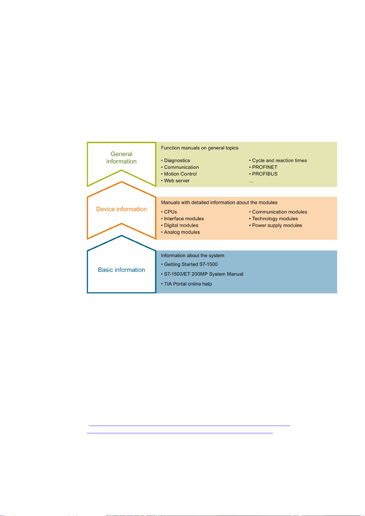
Device information
General information
The documentation for the SIMATIC S7-1500 automation system and the SIMATIC
ET 200MP distributed I/O system is arranged into three areas.
This arrangement enables you to access the specific content you require.
System Manual and Getting Started describe in detail the configuration, installation, wiring
and commissioning of the SIMATIC S7-1500 and ET 200MP systems. The STEP 7 online
help supports you in the configuration and programming.
Manuals contain a compact description of the module-specific information, such as
properties, terminal diagrams, characteristics, technical specifications.
The function manuals contain detailed descriptions on general topics regarding the SIMATIC
S7-1500 and ET 200MP systems, e.g. diagnostics, communication, Motion Control, Web
server.
You can download the documentation free of charge from the Internet
(http://www.automation.siemens.com/mcms/industrial-automation-systems-
simatic/en/manual-overview/tech-doc-controllers/Pages/Default.aspx).
Changes and supplements to the manuals are documented in a Product Information.
S7-1500 Motion Control V13 Update 3
Function Manual, 07/2014, A5E03879256-AC
13
Page 14

Guide to documentation S7-1500 / ET 200MP
Manual Collection S7-1500 / ET 200MP
My Documentation Manager
Applications & Tools
CAx Download Manager
The Manual Collection contains the complete documentation on the SIMATIC S7-1500
automation system and the ET 200MP distributed I/O system gathered together in one file.
You can find the Manual Collection on the Internet
(http://support.automation.siemens.com/WW/view/en/86140384).
The My Documentation Manager is used to combine entire manuals or only parts of these to
your own manual.
You can export the manual as PDF file or in a format that can be edited later.
You can find the My Documentation Manager on the Internet
(http://support.automation.siemens.com/WW/view/en/38715968).
Applications & Tools supports you with various tools and examples for solving your
automation tasks. Solutions are shown in interplay with multiple components in the system separated from the focus in individual products.
You can find Applications & Tools on the Internet
(http://support.automation.siemens.com/WW/view/en/20208582).
The CAx Download Manager is used to access the current product data for your CAx or CAe
systems.
You configure your own download package with a few clicks.
In doing so you can select:
● Product images, 2D dimension drawings, 3D models, internal circuit diagrams, EPLAN
macro files
● Manuals, characteristics, operating manuals, certificates
● Product master data
You can find the CAx Download Manager on the Internet
(http://support.automation.siemens.com/WW/view/en/42455541).
S7-1500 Motion Control V13 Update 3
14 Function Manual, 07/2014, A5E03879256-AC
Page 15

2
2.1
Integrated Motion Control Functionality of the CPU S7-1500
S7-1500 Motion Control supports controlled positioning and moving of axes and is an
integral part of every CPU S7-1500 as well as every CPU S7-1500SP. The Motion Control
functionality supports the technology objects rotation axis, positioning axis, synchronous axis
and external encoders.
Drives with PROFIdrive capability and drives with analog setpoint interface are controlled by
means of standardized Motion Control instructions according to PLCopen.
The axis control panel and comprehensive online and diagnostic functions support easy
commissioning and optimization of drives.
S7-1500 Motion Control is constantly integrated into the CPU S7-1500 system diagnostics.
S7-1500 Motion Control V13 Update 3
Function Manual, 07/2014, A5E03879256-AC
15
Page 16
Introduction
2.2
Principle of operation of S7-1500 Motion Control
Overview
2.2 Principle of operation of S7-1500 Motion Control
You create a project, configure technology objects, and load the configuration into the CPU
using the TIA Portal. The Motion Control functionality is processed in the CPU.
You control the technology objects with the Motion Control instructions in your user program.
The TIA Portal provides additional functions for commissioning, optimization (Page 199) and
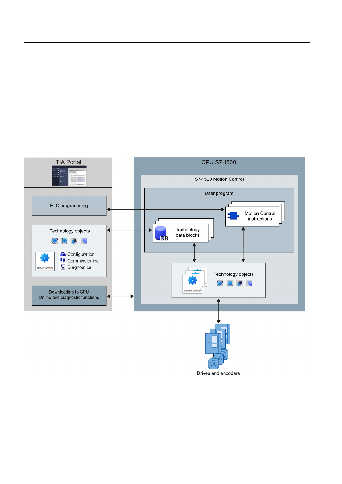
diagnostics (Page 214).
The following figure shows schematically the user interfaces and the integration of Motion
Control into the CPU S7-1500. The concepts are then briefly explained:
S7-1500 Motion Control V13 Update 3
16 Function Manual, 07/2014, A5E03879256-AC
Page 17
Introduction
TIA Portal
Technology objects
Speed axis technology object
Positioning axis technology object
2.2 Principle of operation of S7-1500 Motion Control
The TIA Portal supports you in the planning and commissioning of Motion Control
functionality:
● Integrating and configuring hardware
● Creating and configuring technology objects
● Creating the user program
● Downloading to CPU
● Commissioning of axes
● Optimization of drives
● Diagnostics
You use the TIA Portal to configure the hardware, the technology objects as well as your
user program. You download the program you created to the CPU. You test your user
program and diagnose the hardware with the online and diagnostic functions of the
TIA Portal.
Technology objects represent real objects (e.g., a drive) in the controller. You can call the
functions of the technology objects by means of Motion Control instructions in your user
program. The technology objects provide open- and closed-loop control of the movement of
the real objects, and report status information (e.g. the current position).
The configuration of the technology objects represents the properties of the real object. The
configuration data are stored in a technology data block.
The following technology objects are available for Motion Control:
●
●
The speed axis technology object ("TO_SpeedAxis") permits the specification of the
speed for a drive. You program the movement of the axis with Motion Control
instructions.
The positioning axis technology object ("TO_PositioningAxis") permits the positioncontrolled positioning of a drive. You assign positioning jobs to the axis with Motion
Control instructions in your user program.
S7-1500 Motion Control V13 Update 3
Function Manual, 07/2014, A5E03879256-AC
17
Page 18
Introduction
Synchronous axis technology object
External encoder technology object
Technology data block
Motion Control instructions
User program
2.2 Principle of operation of S7-1500 Motion Control
●
The synchronous axis technology object ("TO_SynchronousAxis") includes all functions of
the positioning axis technology object. You can also interconnect the axis with a master
value so that the axis follows the position change of a leading axis in synchronous
operation.
●
The external encoder technology object ("TO_ExternalEncoder") detects a position, and
makes it available to the controller. The detected position can be evaluated in the user
program.
The properties of real objects are configured by means of the technology objects and saved
in a technology data block. The technology data block contains all configuration data,
setpoint and actual values, and status information of the technology object. The TIA Portal
automatically creates the technology data block when the technology object is created. You
access the data of the technology data block with your user program.
With the Motion Control instructions you perform the desired functionality in the technology
objects. The Motion Control instructions are available in the TIA Portal under "Instructions >
Technology > Motion Control > S7-1500 Motion Control".
The Motion Control instructions conform to PLCopen (version 2.0).
The Motion Control instructions and the technology data block represent the programming
interfaces for the technology objects. Use the Motion Control instructions to start Motion
Control jobs at technology objects in your user program. You track the status of running jobs
with the output parameters of the Motion Control instructions. You access status information
of the technology object with the technology data block and change specific configuration
parameters during runtime.
S7-1500 Motion Control V13 Update 3
18 Function Manual, 07/2014, A5E03879256-AC
Page 19
Introduction
Drives and encoders
2.2 Principle of operation of S7-1500 Motion Control
Drives permit the movement of the axis. They are integrated into the hardware configuration.
When you perform a Motion Control job in your user program, the technology object takes
over the control of the drive and the reading in of values from position encoders.
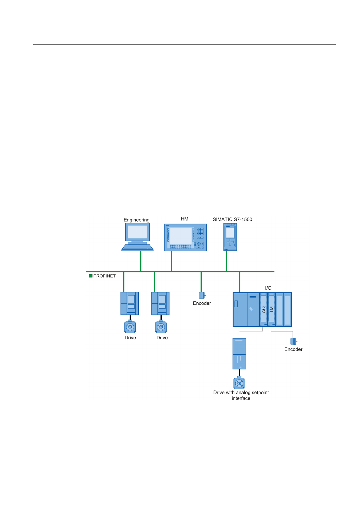
Drives and encoders with PROFIdrive capability are connected by means of PROFIdrive
frames. The following connections are possible:
● PROFINET IO
● PROFIBUS DP
● Technology module (TM)
Drives with analog setpoint interfaces are connected using an analog output (AQ) and an
optional enable signal. Analog inputs and outputs are made available by means of
corresponding IO modules.
A drive is also called an actuator, and an encoder is also called a sensor.
The figure below shows an example configuration in which all components are connected to
the CPU by means of PROFINET IO:
S7-1500 Motion Control V13 Update 3
Function Manual, 07/2014, A5E03879256-AC
19
Page 20

3
3.1
Functions
Function
Speed axis
Positioning axis
Synchronous axis
External encoder
Motion Control instructions (user program)
Enable, disable technology objects
home position
Moving axes in jog mode
Moving axes with the specified speed
Position axis relatively
Position axis absolutely
Start gearing
technology objects
TIA Portal
TIA Portal
("Kv" factor)
You can perform the Motion Control function by means of Motion Control instructions in your
user program or the TIA Portal (under Commissioning).
The following table shows the functions that are supported by technology objects:
"MC_Power (Page 234)"
"MC_Home (Page 239)"
Homing technology objects, setting
"MC_MoveJog (Page 244)"
"MC_MoveVelocity (Page 249)"
"MC_MoveRelative (Page 255)"
"MC_MoveAbsolute (Page 260)"
"MC_MoveSuperimposed
(Page 265)"
Superimposed positioning of axes
"MC_GearIn (Page 270)"
"MC_Halt (Page 275)"
Stop axis
"MC_Reset (Page 279)"
Acknowledging alarms, restarting
X X X X
- X X X
X X X -
X X X -
- X X -
- X X -
- X X -
- - X -
X X X -
X X X X
"Axis control panel (Page 202)"
Moving and homing axes using the
"Optimization (Page 207)"
Optimization of position control
S7-1500 Motion Control V13 Update 3
20 Function Manual, 07/2014, A5E03879256-AC
X X X -
- X X -
Page 21
Basics
3.2
Scale
3.3
Speed-controlled axis technology object
3.2 Scale
For information on the number of technology objects that may be used, refer to the technical
specifications of the utilized CPU.
A synchronous axis requires twice as many resources as a speed-controlled axis or
positioning axis. You can configure two fewer speed or positioning axes for every
synchronous axis you use.
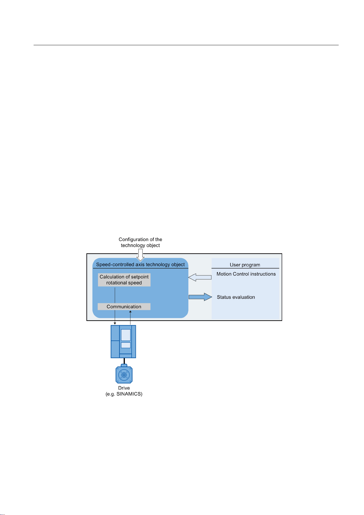
The speed axis technology object calculates speed setpoints, taking account of the specified
dynamics, and outputs them to the drive. All movements of the speed axis occur under
speed control. The system takes account of an existing load gear.
A drive is assigned to each speed axis by means of a PROFIdrive frame, or by means of an
analog setpoint interface.
The speed is specified in revolutions per unit of time.
The following figure shows the basic principle of operation of the speed axis technology
object:
S7-1500 Motion Control V13 Update 3
Function Manual, 07/2014, A5E03879256-AC
21
Page 22
Basics
3.4
Positioning axis technology object
3.4 Positioning axis technology object
The positioning axis technology object calculates position setpoints, taking account of the
specified dynamics, and outputs corresponding speed control setpoints to the drive. All
movements of the positioning axis occur under position control. For absolute positioning, the
physical position must be known to the positioning axis technology object.
Each positioning axis is assigned a drive by means of a PROFIdrive frame or by means of
an analog setpoint interface, and an encoder by means of a PROFIdrive frame.
The relationship between the encoder values and a defined position is created by assigning
parameters to the mechanical properties and the encoder settings, as well as to a homing
process. The technology object can also perform movements without a position relationship,
and relative position movements, even without being in a homed status.
Depending on the execution of the mechanics, a positioning axis is implemented as linear
axis or rotary axis (Page 26).
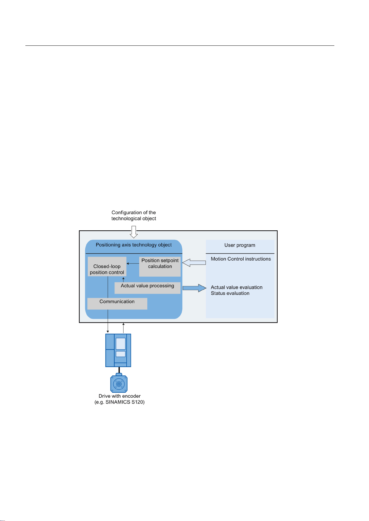
The figure below shows the basic principle of operation of the positioning axis technology
object:
S7-1500 Motion Control V13 Update 3
22 Function Manual, 07/2014, A5E03879256-AC
Page 23
Basics
3.5
Synchronous axis technology object
Relative position relationship
Synchronization
Travel synchronous
3.5 Synchronous axis technology object
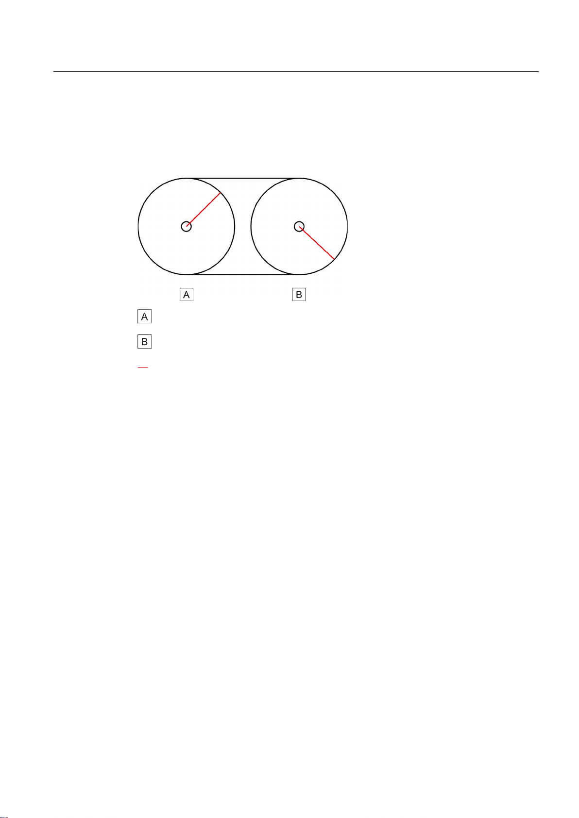
The synchronous axis technology object follows the position change of a leading axis in
relative synchronous operation. A relative gearing exists, for example, when two
mechanically coupled rollers are driven by the same motor:
Leading axis (driven axis)
Following axis
The change of the leading axis position setpoint is multiplied by a specified gear ratio and
passed on to the following axis as setpoint. The synchronous axis technology object outputs
this setpoint as speed setpoint to the drive limited to the maximum speed of the drive
(<TO>.Actor.DriveParameter.MaxSpeed).
The synchronous axis technology object includes all functions of the positioning axis
technology object. All movements of the synchronous axis occur under position control.
If the synchronous axis is operated without synchronous operation, the dynamic limits
configured at the technology object apply.
If the synchronous axis is operated as following axis in synchronous operation, the following
dynamic limits apply depending on the status of the synchronous operation.
●
During synchronization, dynamic limits configured at the technology object apply to the
lead axis and the following axis respectively.
●
If the synchronous axis is operated as following axis, the dynamic limits of the leading
axis are multiplied by the gear ratio apply. The configured dynamic limits of the following
axis are ignored. The dynamic of the following axis is limited to the maximum speed of
the drive.
The following hardware components are assigned to each synchronous axis:
● A drive by means of a PROFIdrive frame or by means of an analog setpoint interface
("MC_GearIn.InGear" = TRUE)
S7-1500 Motion Control V13 Update 3
Function Manual, 07/2014, A5E03879256-AC
● An encoder by means of a PROFIdrive frame
Depending on the execution of the mechanics, a synchronous axis is implemented as linear
axis or rotary axis (Page 26).
23
Page 24
Basics
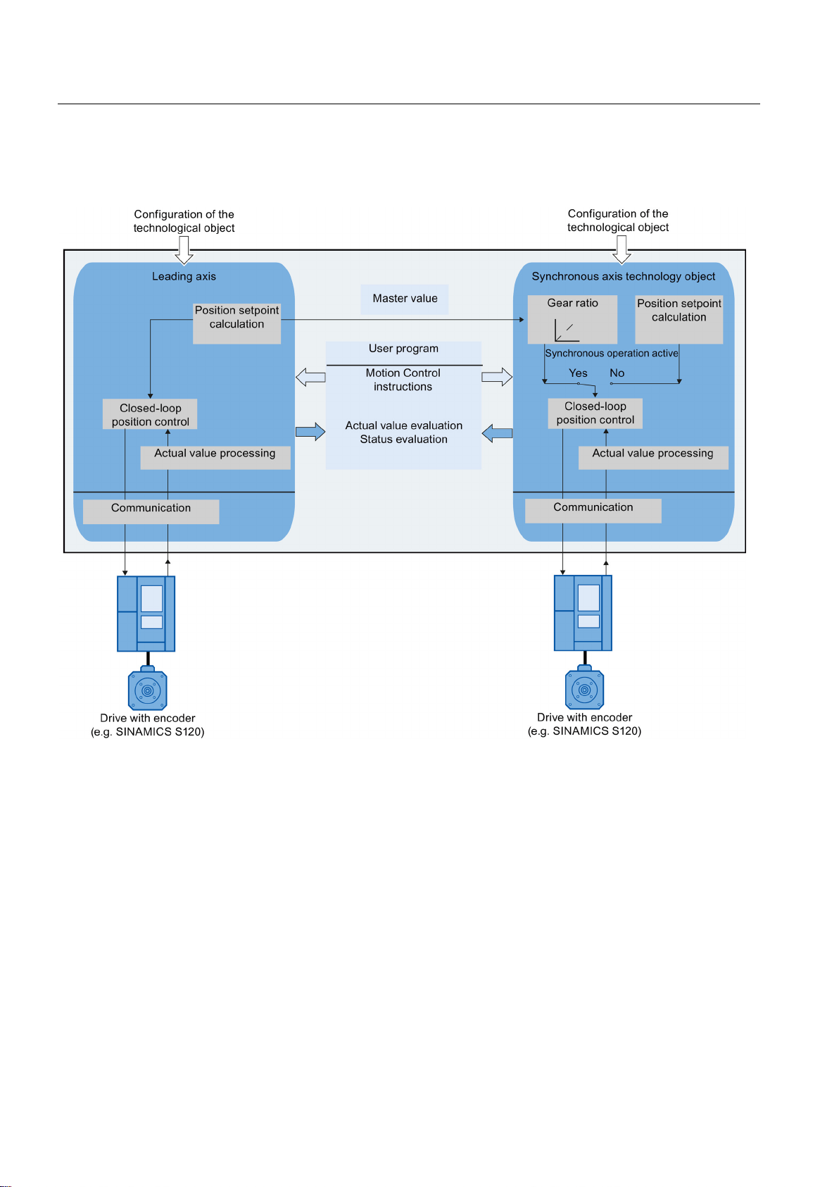
3.5 Synchronous axis technology object
The figure below shows the basic principle of operation of the synchronous axis technology
object:
S7-1500 Motion Control V13 Update 3
24 Function Manual, 07/2014, A5E03879256-AC
Page 25
Basics
3.6
External encoder technology object
Linear system of units
Rotary system of units
Note
The positioning axis/synchronous axis technology objects and external encoder are
independent of each other, and cannot be coupled to each other. The actual position of an
external encoder cannot be used for position control of a
axis.
3.6 External encoder technology object
The external encoder technology object detects a position, and makes it available to the
controller.
The relationship between the encoder values and a defined position is created by assigning
parameters to the mechanical properties and the encoder settings, as well as to a homing
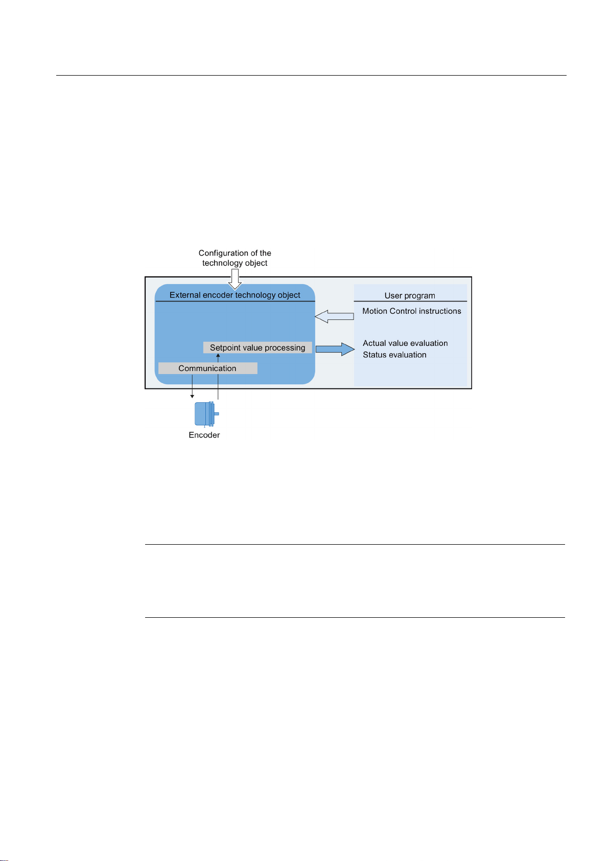
process.
The following figure shows the basic principle of operation of the external encoder
technology object:
Specification of the position occurs according to the selected system of units:
●
The position is specified as a linear measure, e.g. millimeters (mm).
●
The position is specified as an angular measure, e.g. degrees (°).
positioning axis or synchronous
S7-1500 Motion Control V13 Update 3
Function Manual, 07/2014, A5E03879256-AC
25
Page 26
Basics
3.7
Axis types
Linear axis
Rotary axis
3.8
Modulo setting
3.7 Axis types
Axes can be configured with different axis types:
● Positioning and synchronous axes can be configured as rotary or linear axis.
● Speed axes are always rotary axes.
Depending on the execution of the mechanics, an axis is implemented as a linear axis or
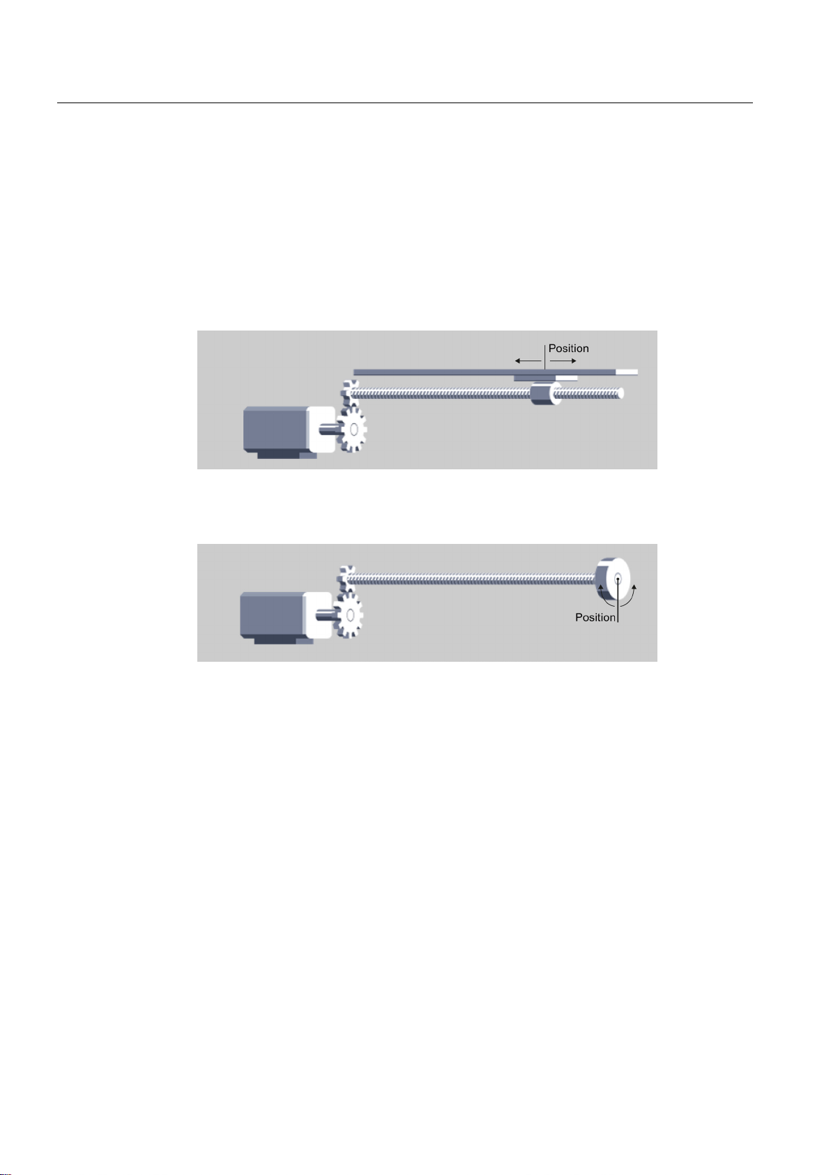
rotary axis:
●
For linear axes, the position of the axis is specified as a linear measure,
e.g. millimeters (mm).
●
For rotary axes, the position of the axis is specified as an angular measure,
e.g. degrees (°).
The positioning axis, synchronous axis and external encoder technology objects can be
enabled with the "Modulo" setting.
If an axis is moved in only one direction, the position value continually increases. To limit the
position value to a recurring reference system, you can enable the "Modulo" setting.
When "modulo" is enabled, the position value of the technology object is represented by
means of a recurring modulo range. The modulo range is defined by the start value and the
length.
For example, to limit the position value of a rotary axis to a full rotation, the modulo range
can be defined with start value = 0° and length = 360°. With an encoder resolution of
0.1°/encoder step, the position value is represented in the modulo range 0° to 359.9°.
S7-1500 Motion Control V13 Update 3
26 Function Manual, 07/2014, A5E03879256-AC
Page 27

Basics
3.9
Units of measure
Position
Velocity
nm, μm, mm, m, km
mm/s, mm/min, mm/h, m/s, m/min, m/h, km/min, km/h
in, ft, mi
in/s, in/min, ft/s, ft/min, mi/h
°, rad
°/s, °/min, rad/s, rad/min
Note
When setting or changing the units of measurement, note the effect on the depiction and the
user program:
•
•
•
•
All information and displays are output in the selected unit of measure.
3.9 Units of measure
The table below shows the supported units of measure for position and velocity:
The acceleration is configured accordingly as unit of measure of the position/s².
The jerk is configured accordingly as unit of measure of the position/s³.
The speed is configured as revolutions per unit of time: 1/s, 1/min, 1/h
Depiction in the technology data block
Supply to the parameters in the user program
Input and display of the position and speed in the TIA Portal
Setpoint settings by leading axes in synchronous operation
S7-1500 Motion Control V13 Update 3
Function Manual, 07/2014, A5E03879256-AC
27
Page 28

Basics
3.10
Drive and encoder connection
3.10.1
Brief description
PROFIdrive
3.10 Drive and encoder connection
A speed axis is assigned a drive.
A positioning axis/synchronous axis is assigned a drive and an encoder.
An external encoder is assigned an encoder.
The setpoint value at the drive is specified either with PROFIdrive message frames, or with
an analog output.
The following connection options are available for an encoder:
● Encoder to drive
● Encoder on technology module
● PROFIdrive encoder directly to PROFIBUS DP / PROFINET IO
The encoder value is transmitted exclusively via PROFIdrive message frames.
PROFIdrive is the standardized standard profile for drive technology in the connection of
drives and encoders via PROFIBUS DP and PROFINET IO.
Drives that support the PROFIdrive profile are connected according to the PROFIdrive
standard.
Communication between controller and drive/encoder is by means of various PROFIdrive
message frames. Each of the message frames has a standardized structure. Depending on
the application, you can select the applicable message frame. Control words and status
words as well as setpoints and actual values are transmitted in the PROFIdrive message
frames.
The PROFIdrive profile likewise supports the "Dynamic Servo Control" (DSC) control
concept. DSC uses rapid position control in the drive. This can be used to solve highly
dynamic positioning jobs.
S7-1500 Motion Control V13 Update 3
28 Function Manual, 07/2014, A5E03879256-AC
Page 29
Basics
3.10.2
Frames
3.10 Drive and encoder connection
The transmission of the encoder value occurs either in a frame together with the setpoint
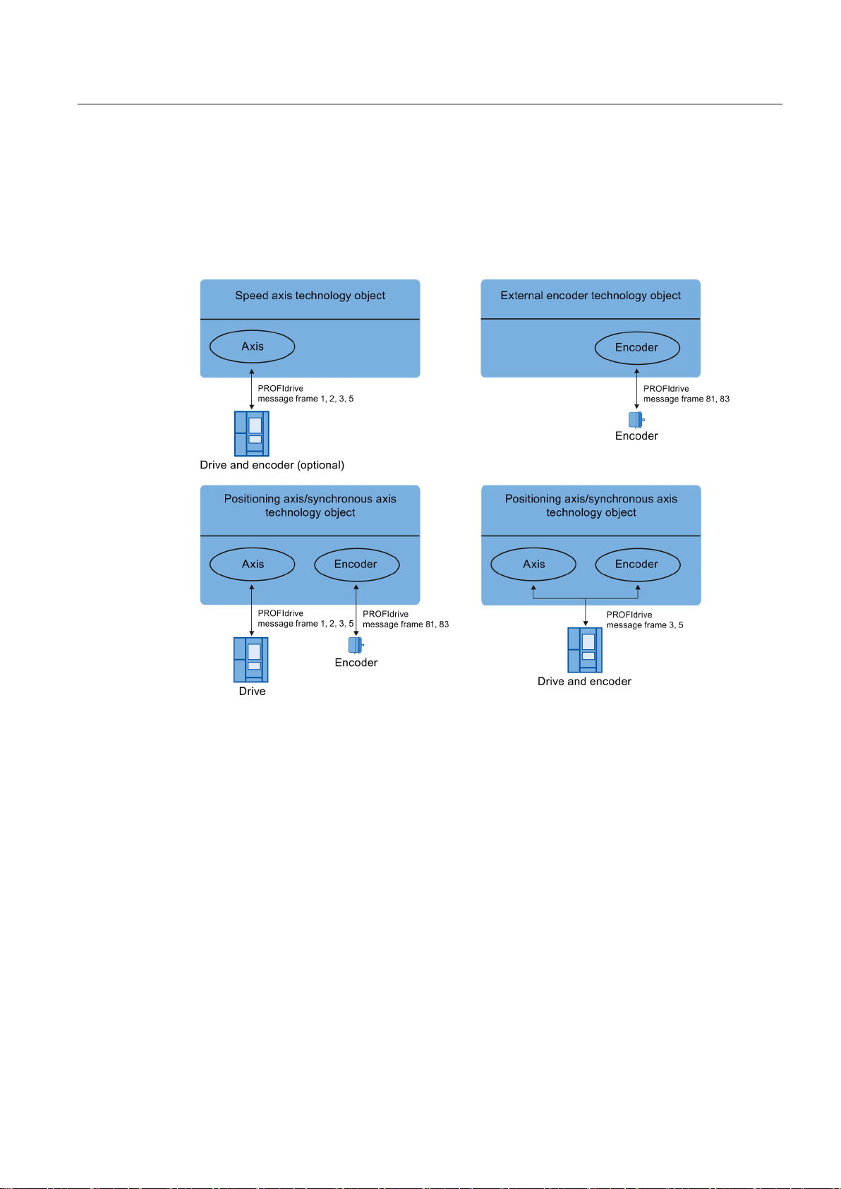
(frame 3 or frame 5), or in a separate encoder frame (frame 81 or frame 83).
The following figure represents the relationship between the technology objects and the
drives / encoders:
Explanation of the figure:
● The setpoint of a speed axis is transmitted to a drive via PROFIdrive frame 1, 2, 3 or 5.
● The encoder value of an external encoder is transmitted via PROFIdrive frame 81 or 83.
● The setpoint of a positioning axis/synchronous axis is transmitted to a drive via
PROFIdrive frame 1, 2, 3 or 5
● Encoder value of the positioning axis/synchronous axis
The encoder value can be transmitted in the following PROFIdrive frames:
– Transmission in the same PROFIdrive frame, in which the setpoint is also transmitted.
For example, with PROFIdrive frame 3 or 5
– Transmission in PROFIdrive frame 81 or 83.
S7-1500 Motion Control V13 Update 3
Function Manual, 07/2014, A5E03879256-AC
29
Page 30

Basics
Frame types
Frame
Brief description
Standard frames
Standard frames encoder
3.10 Drive and encoder connection
The following table shows the supported PROFIdrive frame types for the assignment of
drives and encoders:
1
2
3
5
81
83
• 16 bit speed setpoint (NSET)
• 16 bit actual speed value (NACT),
• 32 bit speed setpoint (NSET)
• 32 bit actual speed (NACT)
• Signs of life
• 32 bit speed setpoint (NSET)
• 32 bit actual speed (NACT)
• Encoder actual value
• Signs of life
• 32 bit speed setpoint (NSET)
• 32 bit actual speed (NACT)
• Dynamic Servo Control (DSC)
• Encoder actual value
• Signs of life
• Encoder actual value
• Signs of life
• 32 bit actual speed (NACT)
• Encoder actual value
• Signs of life
When connecting by means of a PROFIdrive frame, the drives and encoders are handled
and switched on in accordance with the PROFIdrive profile.
S7-1500 Motion Control V13 Update 3
30 Function Manual, 07/2014, A5E03879256-AC
Page 31

Basics
3.10.3
Setting reference values
Frame settings
Setting in the TIA Portal
Controller
tag in the technology data block
PROFIdrive
parameter
Frame
<TO>.Actor.Interface.Telegram
P922
drives: P2000)
drives: P1082)
Encoder message frame
<TO>.Sensor[n].Interface.Telegram
P922
(linear or rotary encoder)
2: cyclic absolute
marks on the linear measuring system.
(rotary encoder)
actual encoder value, linear or rotary encoder)
lute encoder value, linear or rotary encoder)
(rotary absolute value encoder)
3.10 Drive and encoder connection
The reference values for the drive connection and encoder connection must be set
identically in the controller, and in the drive or encoder.
The setpoint speed setpoint NSET and the actual speed value NACT are transmitted in the
PROFIdrive frame as a percentage value relative to the reference speed. The reference
value for the speed must be set identically in the controller and in the drive.
The resolution of the actual value in the PROFIdrive frame must likewise be set identically in
the controller and in the drive or encoder.
The controller settings are made in the TIA Portal under "Technology object > Configuration
> Hardware interface > Data transmission".
The settings for drive and encoder are set in the configuration for the respective hardware.
The following table contrasts the controller settings and corresponding PROFIdrive
parameters (<TO> stands for the applicable technology object):
Reference speed in [rpm] <TO>.Actor.DriveParameter.ReferenceSpeed (SINAMICS
Maximum speed of the motor in [rpm] <TO>.Actor.DriveParameter.MaxSpeed (SINAMICS
Encoder system
Encoder type
0: incremental
1: absolute
Resolution (linear encoder)
The grid spacing is specified on the nameplate
of the sensor as a separation distance of the
Increments per revolution
Number of bits for fine resolution XIST1 (cyclic
Number of bits for fine resolution XIST2 (abso-
Differentiable encoder revolutions
<TO>.Sensor[n].System P979[1] Bit0
<TO>.Sensor[n].Type P979[5]
<TO>.Sensor[n].Parameter.Resolution P979[2]
<TO>.Sensor[n].Parameter.StepsPerRevolution P979[2]
<TO>.Sensor[n].Parameter.FineResolutionXist1 P979[3]
<TO>.Sensor[n].Parameter.FineResolutionXist2 P979[4]
<TO>.Sensor[n].Parameter.DeterminableRevolutions P979[5]
S7-1500 Motion Control V13 Update 3
Function Manual, 07/2014, A5E03879256-AC
31
Page 32
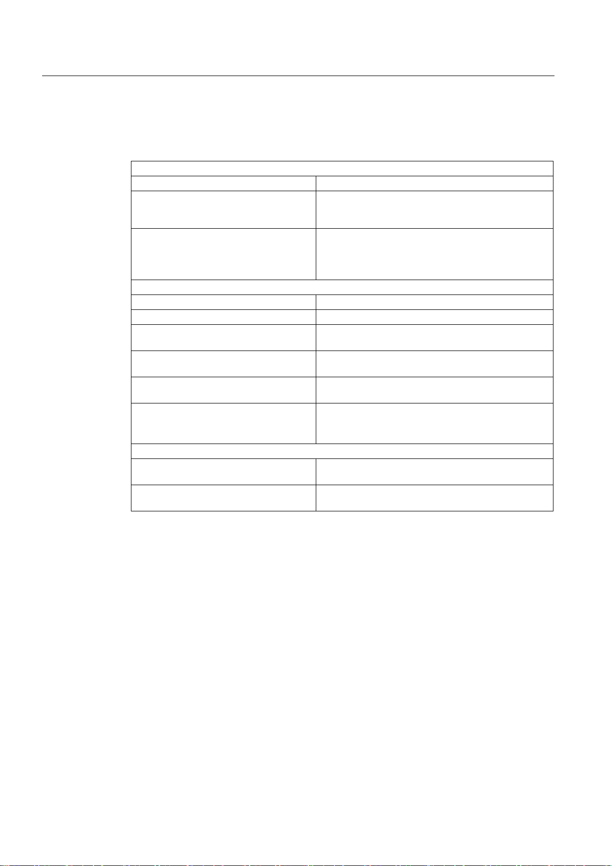
Basics
3.10.4
Tags
Drive frame
<TO>.Actor.Interface.Telegram
Frame number
value
Analog setpoint: MaxSpeed ≤ 1.17 × ReferenceSpeed)
Encoder frame
<TO>.Sensor[n].Interface.Telegram
Frame number
<TO>.Sensor[n].System
Encoder system linear or rotary
lute
Revolution
two marks.
Fine resolution
Xist1
encoder value)
Xist2
of the encoder)
3.10 Drive and encoder connection
The following technology object tags are relevant for the connection of drives and encoders:
<TO>.Actor.DriveParameter.Reference
Speed
<TO>.Actor.DriveParameter.MaxSpeed Maximum value for the setpoint speed of the drive
<TO>.Sensor[n].Type Encoder type, incremental, absolute or cyclically abso-
<TO>.Sensor[n].Parameter.StepsPer
<TO>.Sensor[n].Parameter.Determinable
Revolutions
<TO>.Sensor[n].Parameter.Resolution Resolution for linear encoder
Reference velocity / reference speed for the velocity /
speed (NSET), which is transmitted as a percentage
(NSET)
(PROFIdrive: MaxSpeed ≤ 2 × ReferenceSpeed
Increments per revolution for rotary encoder
Number of differentiable encoder revolutions for a multiturn absolute value encoder
The grid spacing corresponds to the interval between
<TO>.Sensor[n].Parameter.FineResolution
<TO>.Sensor[n].Parameter.FineResolution
Number of bits for fine resolution XIST1 (cyclic actual
Number of bits for fine resolution XIST2 (absolute value
S7-1500 Motion Control V13 Update 3
32 Function Manual, 07/2014, A5E03879256-AC
Page 33

Basics
3.11
Safety functions in the drive
3.11.1
Brief description
3.11.2
Safe Torque Off (STO)
Behavior with S7-1500 Motion Control
3.11 Safety functions in the drive
The safety functions are internal drive functions and are described in detail in the relevant
drive documentation.
The following section describes the reactions to the supported safety functions at the
controller end .
The safety features are only supported for the drive connection via PROFIdrive.
The following safety features are supported by S7-1500 Motion Control:
● Safe Torque Off (STO)
● Safe Stop 1 (SS1)
● Safe Stop 2 (SS2)
The active safety functions can also be evaluated via Safety Info Channel (SIC). Since the
SIC is not a component of S7-1500 Motion Control, you must evaluate it separately in the
user program.
The Safe Torque Off (STO) safety function is the most common and basic internal safety
function in the drive. STO ensures that no torque generating energy acts on a drive. This
prevents an unintended startup of the controller. The pulses of the drive are eliminated. The
drive is reliably torque-free. This state is monitored internally in the drive.
You can use STO when the drive comes to a standstill in a sufficiently short time due to the
load torque or friction. Other areas of use are where "coasting" of the drive has no relevance
for safety.
When STO is triggered in the drive, technology alarm 421 is output, and the technology
object is disabled (alarm reaction: Remove enable).
When the STO signal is no longer present in the drive, you can enable the technology object
again after acknowledgment of the alarm.
S7-1500 Motion Control V13 Update 3
Function Manual, 07/2014, A5E03879256-AC
33
Page 34

Basics
3.11.3
Safe Stop 1 (SS1)
Behavior with S7-1500 Motion Control
3.11.4
Safe Stop 2 (SS2)
Behavior with S7-1500 Motion Control
3.11 Safety functions in the drive
The Safe Stop 1 (SS1) safety function brings a drive to standstill quickly and safely via a
drive-internal rapid stop ramp. Safe Torque Off (STO) is activated after standstill. STO
ensures that no torque generating energy acts on a drive. This prevents an unintended
startup of the controller.
You can use the SS1 safety function when a fast stop of the drive with a subsequent
transition to STO is required. SS1 is used, for example, to quickly stop high inertia or brake
drives quickly and safely at high speeds
When SS1 is triggered, the drive decelerates at a drive-internal rapid stop ramp and
automatically triggers the Safe Torque Off (STO) safety function.
When SS1 is triggered in the drive, the technology alarm 550 (alarm reaction: Follow-up
setpoint) is output and the actual values supplied by the drive are automatically tracked as
setpoints. The actual values are not monitored at the controller end. When standstill is
achieved, technology alarm 421 is output, and the technology object is disabled (alarm
reaction: Remove enable).
When the SS1 signal is no longer present in the drive, you can enable the technology object
again after the acknowledgment of the alarm.
The Safe Stop 2 (SS2) safety function brings a drive to standstill quickly and safely via a
drive-internal rapid stop ramp. When standstill is achieved, the standstill position is
monitored at the drive end. The drive can deliver full torque to maintain the standstill.
SS2, for example, is used for machine tools.
When SS2 is triggered, the drive decelerates at a drive-internal rapid stop ramp. The drive
control monitors the standstill.
When SS2 is triggered in the drive, the technology alarm 550 (alarm reaction: Follow-up
setpoint) is output and the actual values supplied by the drive are automatically tracked as
setpoints. The actual values are not monitored at the controller end.
When the SS2 signal is no longer present in the drive, the drive goes automatically into "read
for operation" mode. The operational readiness of the drive is indicated in the technology
object tags <TO>.StatusDrive.InOperation with TRUE. The technology object is
automatically enabled again after acknowledging the alarm.
S7-1500 Motion Control V13 Update 3
34 Function Manual, 07/2014, A5E03879256-AC
Page 35

Basics
3.12
Actual values
3.12.1
Brief description
3.12.2
Incremental actual value
3.12.3
Absolute actual value
3.12 Actual values
For position-controlled motion and positioning, the controller must know the actual position
value.
The actual position value is provided by a PROFIdrive frame. The actual value is updated
after a one-off transition of the operating mode from STOP to RUN.
The actual values are represented incrementally or absolutely in the PROFIdrive frame, and
standardized in the controller to the technological unit. Homing is used to convert the actual
value to the physical position of the axis, or of the external encoder.
The controller supports the following types of actual values:
● Incremental actual value
● Absolute actual value with the setting absolute (measuring range > traversing range of
the axis)
● Absolute actual value with the setting absolute (measuring range < traversing range of
the axis)
The actual value in the PROFIdrive frame is based on an incremental value.
After POWER ON, position zero is displayed. The actual value is updated after a one-time
transition of the operating mode from STOP to RUN in the STOP and RUN operating modes.
The relationship between the technology object and the mechanical position must be
recreated by means of homing (Page 39).
S7-1500 Motion Control V13 Update 3
Function Manual, 07/2014, A5E03879256-AC
The actual value in the PROFIdrive frame is based on an absolute value.
After POWER ON, position zero is displayed. The actual value is updated after a one-off
transition of the operating mode from STOP to RUN. The supplied absolute value is
assigned to the associated mechanical axis position by means of absolute value adjustment
(Page 56). The absolute value adjustment must be performed once. The absolute value
offset is retentively saved beyond the switching on/off of the controller.
Differentiation of absolute values:
● The measuring range of the encoder is larger than the traversing range of the axis:
Absolute value with absolute setting
● The measuring range of the encoder is smaller than the traversing range of the axis:
Absolute value with cyclically absolute setting
35
Page 36

Basics
Absolute actual value with the setting absolute (measuring range > traversing range)
Absolute actual value with the setting absolute (measuring range < traversing range)
NOTICE
Movements of the axis while the controller is switched off can skew the actual value
3.12.4
Tags
3.12 Actual values
The axis position results directly from the actual encoder value. The traversing range must
be within an encoder measuring range. This means that the zero point of the encoder must
not be located in the traversing range.
When the controller is switched on, the axis position is determined from the absolute
encoder value.
The encoder supplies an absolute value within its measuring range. The controller includes
the traversed measuring ranges and thus determines the correct axis position beyond the
measuring range.
When the controller is switched off, the traversed measuring ranges are saved in the
retentive memory area of the controller.
At the next power-on, the stored overflows are taken into account in the calculation of the
actual position value.
If the axis or the encoder is moved by more than half of the encoder measuring range while
the controller is switched off, then the actual value in the controller is no longer in accord
with the mechanical axis position.
The tags named in the Homing (Page 58) section are relevant for adapting actual values.
S7-1500 Motion Control V13 Update 3
36 Function Manual, 07/2014, A5E03879256-AC
Page 37

Basics
3.13
Mechanics
3.13.1
Brief description
Positioning axis/synchronous axis
External encoder
Speed axis
3.13 Mechanics
For the display and processing of the technology object's position, the decisive factor is
whether the position is represented as a unit of length (linear axis) or as a rotary unit (rotary
axis).
Examples of units of length: mm, m, km
Examples of rotary units: °, rad
For the determination of the physical position from an actual encoder value, the system must
know the various properties and configurations of the mechanics.
The following configuration options for mechanics are supported:
● Load gear
● Leadscrew pitch (linear axes only)
● Type of encoder mounting:
– On the motor side (before the load gear)
– On the load side (after the load gear and as applicable the leadscrew)
– External (e.g. odometer)
● Inversion of the setpoint
● Inversion of the setpoint
The following configuration options for mechanics are supported:
● Measuring gearbox (for rotary encoders)
● Leadscrew (only with linear system of units and rotatory encoders)
● Inversion of the setpoint
The following configuration options for mechanics are supported:
● Load gear
● Inversion of the setpoint
S7-1500 Motion Control V13 Update 3
Function Manual, 07/2014, A5E03879256-AC
37
Page 38

Basics
3.13.2
Tags
Type of motion
1: Rotary motion
Load gear
<TO>.LoadGear.Numerator
Load gear counter
<TO>.LoadGear.Denominator
Load gear denominator
Leadscrew pitch
<TO>.Mechanics.LeadScrew
Leadscrew pitch
Type of encoder mounting
<TO>.Sensor[n].MountingMode
Type of encoder mounting
PerRevolution
mounted encoder
Inversion
<TO>.Actor.InverseDirection
Setpoint inversion
<TO>.Sensor[n].InverseDirection
Actual value inversion
Modulo
<TO>.Modulo.Enable
Enable modulo
<TO>.Modulo.StartValue
Modulo start value
3.13 Mechanics
The following technology object tags are relevant for the setting of the mechanics:
<TO>.Properties.MotionType Indication of linear or rotary motion
0: Linear motion
<TO>.Sensor[n].Parameter.Distance
Load distance per encoder revolution with an externally
<TO>.Modulo.Length Modulo length
S7-1500 Motion Control V13 Update 3
38 Function Manual, 07/2014, A5E03879256-AC
Page 39

Basics
3.14
Homing
3.14.1
Brief description
Homing status
Type of homing
Active homing
Passive homing
Direct homing
Absolute value adjustment
3.14 Homing
With homing, you create the relationship between the position in the technology object and
the mechanical position. The position value in the technology object is assigned to a homing
mark at the same time. This homing mark represents a known mechanical position.
With incremental actual values this process is called homing; with absolute actual values it is
called absolute value adjustment.
Homing is a requirement for the indication of the correct position in the technology object,
and for absolute positioning.
Homing is enabled with the Motion Control instruction "MC_Home", and is enabled for a
single homing process each time.
The technology object tag <TO>.StatusWord.X5 (HomingDone) indicates whether the
technology object has been homed to an axis or external encoder.
Homing can occur by means of an independent movement for homing (active homing), by
means of a homing mark during an application-initiated movement (passive homing), or by
means of direct position assignment.
A distinction is made between the following types of homing:
●
Active homing initiates a homing movement and performs the necessary approach to the
homing mark. When the homing mark is detected, the actual position is set to the
configured value. It is possible to specify an offset from the home position.
When active homing starts, current traversing movements are aborted. The offset is
automatically traversed after the approach to home position.
●
The homing job does not perform its own homing motion. When the homing mark is
detected during an application-initiated motion, the actual position is set to the configured
value.
Passive homing is also called homing on the fly.
●
The homing job directly sets the actual position to the configured value, or offsets it by
this amount.
●
Absolute value adjustment adjusts the position of the technology object to the existing
absolute actual value.
S7-1500 Motion Control V13 Update 3
Function Manual, 07/2014, A5E03879256-AC
39
Page 40

Basics
Homing mode
Homing with zero mark via PROFIdrive frame and proximity switch
Homing with zero mark via PROFIdrive frame
Homing with digital input
3.14.2
Terms
Homing mark
A zero mark
An edge at the digital input
Proximity switch
Homing mark position
Home position
3.14 Homing
Depending on the type of homing mark and of the homing mark search, a distinction is made
among the following homing modes (Page 41):
●
●
●
A homing mark is an input signal, on whose occurrence a known mechanical position can be
assigned to the actual values.
A homing mark can be:
●
The zero mark of an incremental encoder or an external zero mark is used as a homing
mark.
The zero mark is detected at the drive module or encoder module, and transmitted in the
PROFIdrive frame. Perform the setting and evaluation as an encoder zero mark or
external zero mark at the drive module and sensor module.
●
The falling or rising edge at a digital input is used as a homing mark.
If there are several zero marks in the traversing range, the proximity switch permits the
selection of a specific zero mark before or after the proximity switch.
This is the position assigned to the homing mark.
The homing mark position corresponds to the home position minus the home position offset.
At the end of the active homing motion, the axis arrives at the home position.
S7-1500 Motion Control V13 Update 3
40 Function Manual, 07/2014, A5E03879256-AC
Page 41

Basics
Home position offset
Direction reversal at the hardware limit switch (reversing cam)
3.14.3
Homing mode
Homing with zero mark via PROFIdrive frame and proximity switch
Homing with zero mark via PROFIdrive frame
3.14 Homing
The difference between the homing mark position and the home position is the home
position offset.
An offset between homing mark position and home position only has an effect during active
homing. The offset is traversed after the synchronization of the axis via the Motion Control
instruction "MC_Home". For axes with the modulo setting, the home position offset is always
traversed using the direction setting for the shortest path.
Hardware limit switches can be used as reversing cams in active homing. If the homing mark
is not detected or was approached from the wrong side, then the motion continues after the
reversing cam in the opposite direction.
Various homing modes are available for the positioning axis/synchronous axis and external
encoder technology objects with incremental encoders. The homing mode is set in the
configuration.
The system checks for when the proximity switch is reached. After the proximity switch is
reached and is left again in the assigned homing direction, zero mark detection is enabled
via the PROFIdrive message frame.
When the zero mark is reached in the pre-selected direction, then the actual position of the
technology object is set to the homing mark position.
The system enables zero mark detection, as soon as the actual value of the technology
object moves in the assigned homing direction.
When the zero mark is reached in the specified homing direction, the actual position of the
technology object is set to the homing mark position.
S7-1500 Motion Control V13 Update 3
Function Manual, 07/2014, A5E03879256-AC
41
Page 42

Basics
Homing with digital input
Note
The digital inputs must be placed into the process image partition "PIP OB Servo".
The filter time of the digital inputs must be set smaller than the duration of the input signal at
the reference point switch.
See also
3.14 Homing
The system checks the state of the digital input, as soon as the actual value of the axis or
encoder moves in the assigned homing direction.
When the homing mark is reached (setting of the digital input) in the specified homing
direction, the actual position of the technology object is set to the homing mark position.
Homing SINAMICS drives with external zero marks (Page 396)
S7-1500 Motion Control V13 Update 3
42 Function Manual, 07/2014, A5E03879256-AC
Page 43
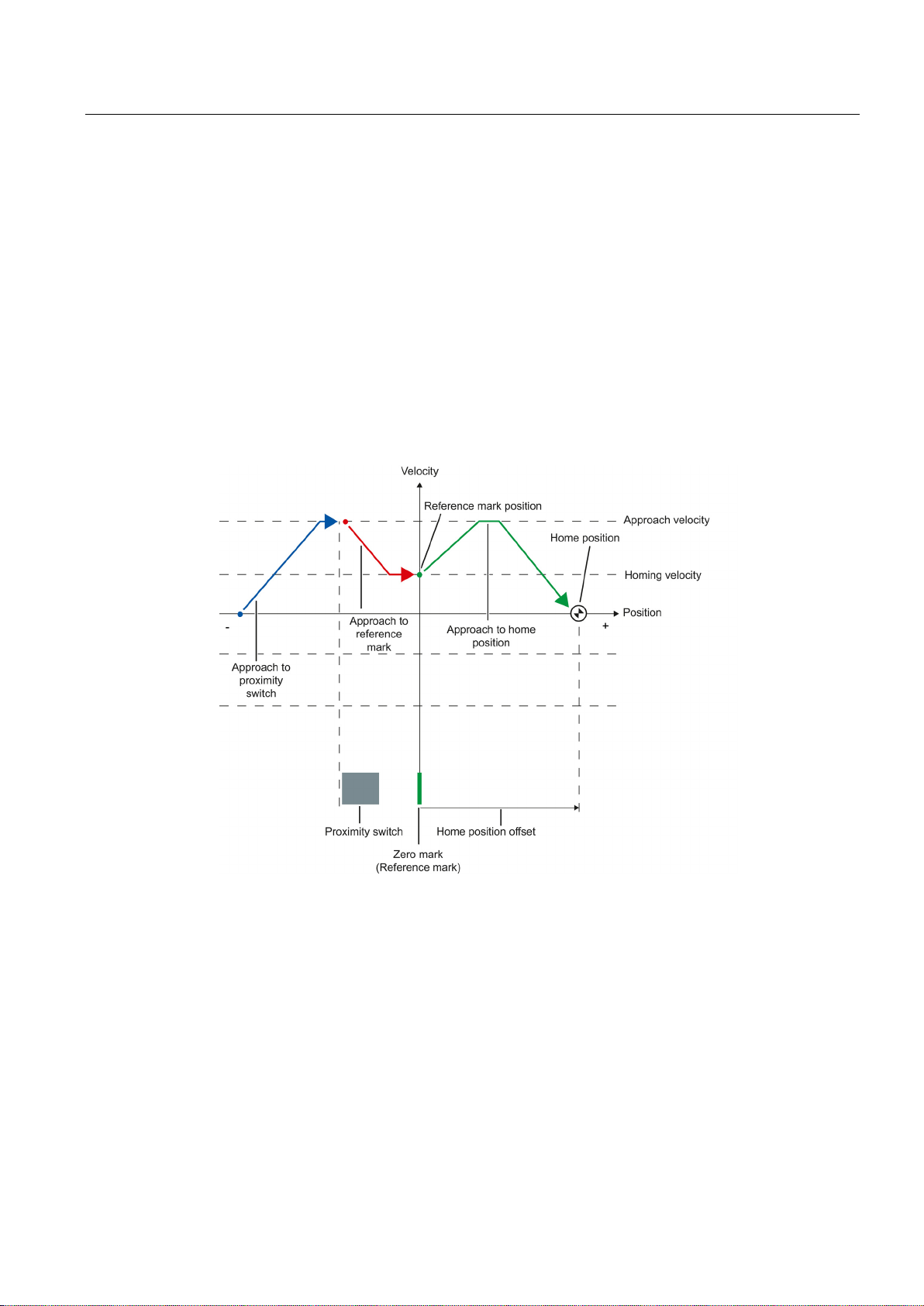
Basics
3.14.4
Active homing with zero mark and proximity switch
Example of homing in the positive direction
3.14 Homing
The following examples show homing motions in the positive and negative directions.
The approach to the homing mark and the home position occurs in the positive direction.
The following figure shows the homing motion with the following settings:
● Active homing with zero mark and proximity switch
● Approach in the positive direction
● Homing in the positive direction
● Positive home position offset
S7-1500 Motion Control V13 Update 3
Function Manual, 07/2014, A5E03879256-AC
43
Page 44
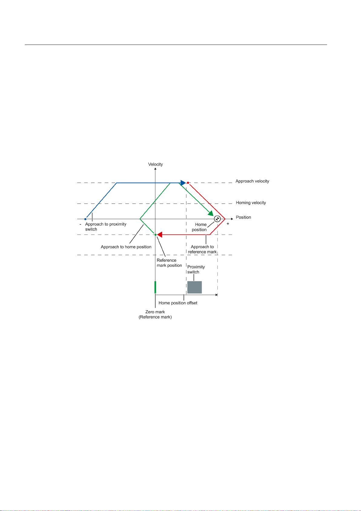
Basics
Example of homing in the negative direction
3.14 Homing
The move to the homing mark occurs in the negative direction by means of a direction
reversal during the homing process. The move to the home position causes another direction
reversal and occurs in the positive direction.
The following figure shows the homing motion with the following settings:
● Active homing with zero mark and proximity switch
● Approach in the positive direction
● Homing in the negative direction
● Positive home position offset
S7-1500 Motion Control V13 Update 3
44 Function Manual, 07/2014, A5E03879256-AC
Page 45

Basics
Motion sequence
Start of active homing via the Motion Control instruction "MC_Home"
Approach to the proximity switch
Detection of the proximity switch in the homing direction, while moving at homing velocity
Departure from the proximity switch, and approach to the homing mark
Detection of the homing mark
Note
Parameter "MC_Home.Mode"
The "MC_Home.Mode" parameter for S7
Control has been standardized within the framework of technology version V2.0. This
results in a new assignment of the parameter values for the "MC_Home.Mode"
parameter. A compariso
V1.0 and V2.0 is available in the section
Approach to the home position
Note
If the velocity on the span from the detection of the proximity switch to the zero mark
cannot be reduced to the homing velocity, then homing occurs at the velocity that
when the zero mark is traversed.
See also
3.14 Homing
The motion occurs in the following sequence:
1.
2.
3.
4.
With the departure from the proximity switch, the detection of the homing mark is
enabled.
5.
When the homing mark is detected, the position of the technology object is set depending
on the configured mode:
– Parameter "Mode" to "MC_Home" = 3
Position = value in parameter "Position" minus
<TO>.Sensor[n].ActiveHoming.HomePositionOffset
– Parameter "Mode" to "MC_Home" = 5
Position = value in the tag <TO>.Homing.HomePosition minus
<TO>.Sensor[n].ActiveHoming.HomePositionOffset
-1200 Motion Control and S7-1500 Motion
n of the "MC_Home.Mode" parameter for technology versions
Version overview (Page 86).
6.
– Parameter "Mode" to "MC_Home" = 3
The axis moves to the position that is specified in the "Position" parameter.
– Parameter "Mode" to "MC_Home" = 5
The axis moves to the position that is specified in the <TO>.Homing.HomePosition
tag.
exists
Homing SINAMICS drives with external zero marks (Page 396)
S7-1500 Motion Control V13 Update 3
Function Manual, 07/2014, A5E03879256-AC
45
Page 46
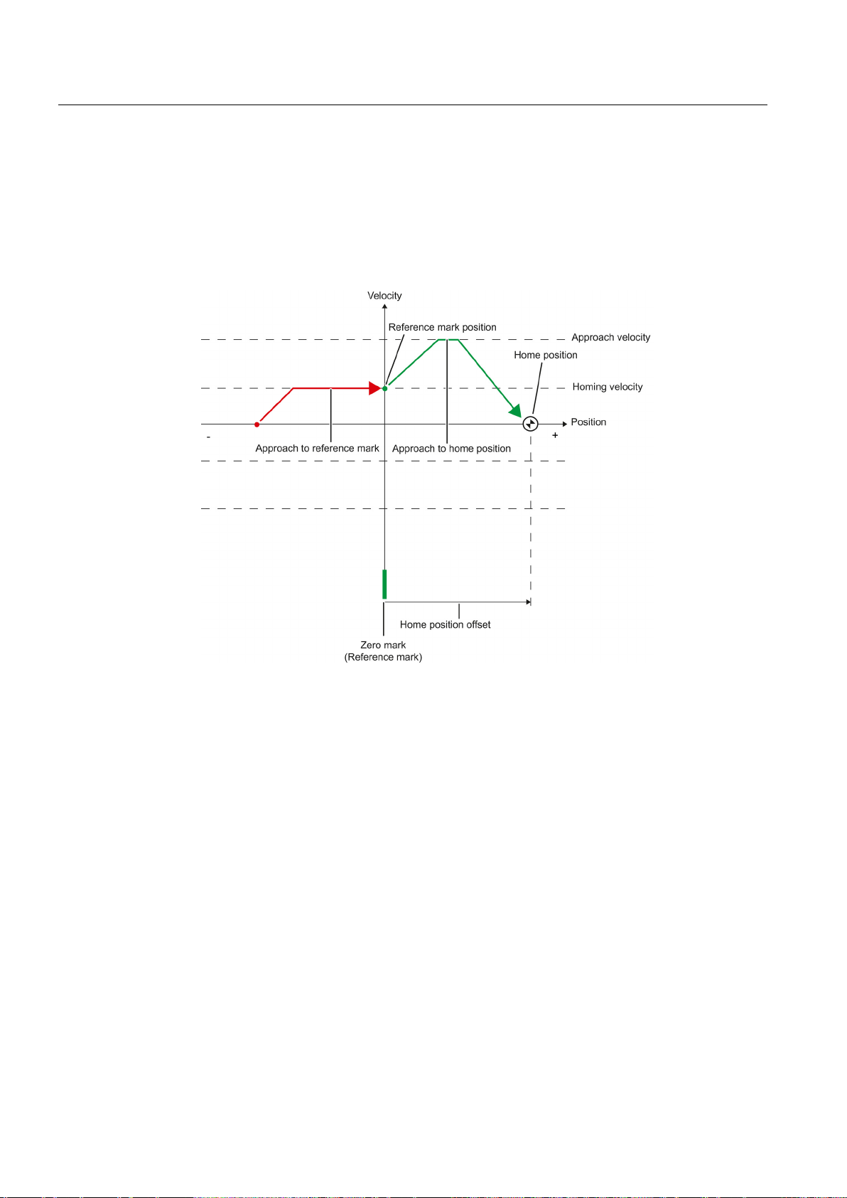
Basics
3.14.5
Active homing with zero mark
3.14 Homing
The following figure shows an example of the homing motion with the following settings:
● Active homing with zero mark
● Homing in the positive direction
● Positive home position offset
S7-1500 Motion Control V13 Update 3
46 Function Manual, 07/2014, A5E03879256-AC
Page 47

Basics
Motion sequence
Start of active homing via the Motion Control instruction "MC_Home"
Move to the homing mark in the homing direction with the homing velocity
Detection of the homing mark
Note
Parameter "MC_Home.Mode"
The "MC_Home.Mode" parameter for S7
Control has been standardized within the framework of technology version V2.0. This
results in a new assignment of the parameter values for the "MC_Home.Mode"
parameter. A compar
V1.0 and V2.0 is available in the section
Approach to the home position
See also
3.14 Homing
The motion occurs in the following sequence:
1.
2.
3.
When the homing mark is detected, the position of the axis or encoder is set depending
on the configured mode:
– Parameter "Mode" to "MC_Home" = 3
Position = value in parameter "Position" minus
<TO>.Sensor[n].ActiveHoming.HomePositionOffset
– Parameter "Mode" to "MC_Home" = 5
Position = value in the tag <TO>.Homing.HomePosition minus
<TO>.Sensor[n].ActiveHoming.HomePositionOffset
-1200 Motion Control and S7-1500 Motion
ison of the "MC_Home.Mode" parameter for technology versions
Version overview (Page 86).
4.
– Parameter "Mode" to "MC_Home" = 3
The axis moves to the position that is specified in the "Position" parameter.
– Parameter "Mode" to "MC_Home" = 5
The axis moves to the position that is specified in the <TO>.Homing.HomePosition
tag.
Homing SINAMICS drives with external zero marks (Page 396)
S7-1500 Motion Control V13 Update 3
Function Manual, 07/2014, A5E03879256-AC
47
Page 48
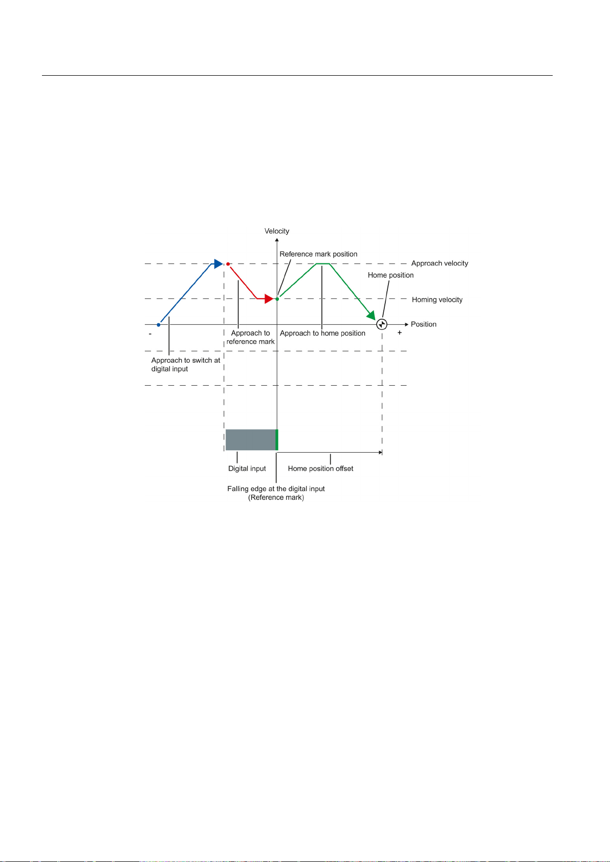
Basics
3.14.6
Active homing with digital input
3.14 Homing
The following figure shows an example of the homing motion with the following settings:
● Active homing with digital input
● Approach in the positive direction
● Homing mark on the positive side of the digital input
● Positive home position offset
S7-1500 Motion Control V13 Update 3
48 Function Manual, 07/2014, A5E03879256-AC
Page 49

Basics
Motion sequence
Start of active homing via the Motion Control instruction "MC_Home"
Detection of the rising edge at the digital input, while moving at homing velocity
Approach to the homing mark
Detection of the homing mark
Note
Parameter "MC_Home.Mode"
The "MC_Home.Mode" parameter for S7
Control has been standardized within the framework of technology version V2.0. This
results in a new assignment of the parameter values for the "MC_Home.Mode"
parameter. A compariso
V1.0 and V2.0 is available in the section
Approach to the home position
Note
If the velocity on the span from the detection of the rising edge to the falling edge cannot
be reduced to the homing velocity, then homing occurs at the velocity that ex
the homing mark is traversed.
3.14 Homing
The motion occurs in the following sequence:
1.
2.
3.
4.
In the example, the falling edge of the switch at the digital input represents the homing
mark.
When the homing mark is detected, the position of the axis or encoder is set depending
on the configured mode:
– Parameter "Mode" to "MC_Home" = 3
Position = value in parameter "Position" minus
<TO>.Sensor[n].ActiveHoming.HomePositionOffset
– Parameter "Mode" to "MC_Home" = 5
Position = value in the tag <TO>.Homing.HomePosition minus
<TO>.Sensor[n].ActiveHoming.HomePositionOffset
-1200 Motion Control and S7-1500 Motion
n of the "MC_Home.Mode" parameter for technology versions
Version overview (Page 86).
5.
– Parameter "Mode" to "MC_Home" = 3
The axis moves to the position that is specified in the "Position" parameter.
– Parameter "Mode" to "MC_Home" = 5
The axis moves to the position that is specified in the <TO>.Homing.HomePosition
tag.
ists when
S7-1500 Motion Control V13 Update 3
Function Manual, 07/2014, A5E03879256-AC
49
Page 50
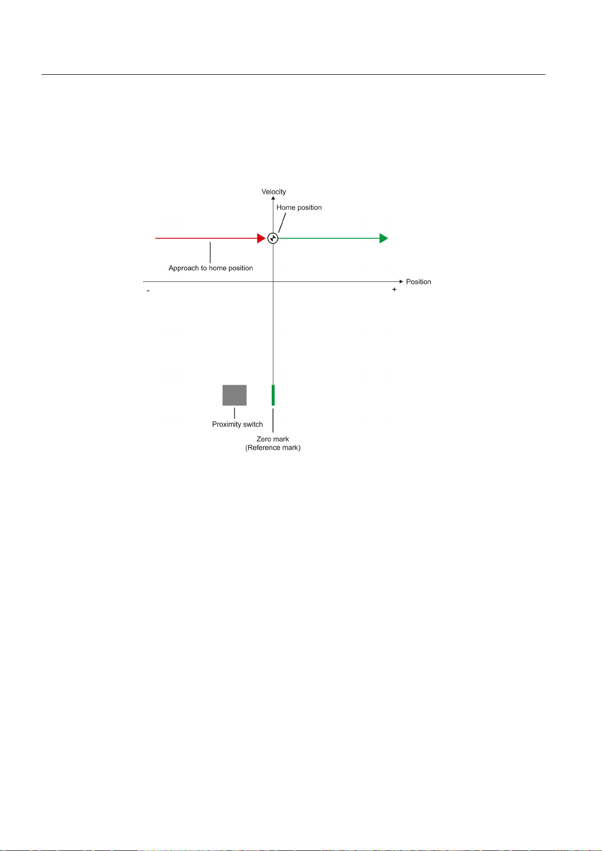
Basics
3.14.7
Passive homing with zero mark and proximity switch
3.14 Homing
The following figure shows an example of the homing motion with the following settings:
● Passive homing with zero mark and proximity switch
● Homing in the positive direction
S7-1500 Motion Control V13 Update 3
50 Function Manual, 07/2014, A5E03879256-AC
Page 51

Basics
Motion sequence
Enablement of passive homing via the Motion Control instruction "MC_Home".
Motion due to a Motion Control job from the application
Detection of the proximity switch
Departure from the proximity switch
Detection of the homing mark
Note
Parameter "MC_Home.Mode"
The "MC_Home.Mode" parameter for S7
Control has been standardized within the framework of technology version V2.0. This
results in a new assignment of the parameter values for the "MC_Home.Mode"
parameter. A compariso
V1.0 and V2.0 is available in the section
Note
If the direction of motion changes after departure from the proximity switch and before
detection of the homing mark, then the proximity switch must be detected again. The
Motion C
3.14 Homing
The motion occurs in the following sequence:
1.
2.
The detection of the proximity switch and of the homing mark is enabled when the actual
position value of the axis or encoder moves in the assigned homing direction.
3.
4.
The departure from the proximity switch enables the detection of the homing mark.
5.
When the homing mark is detected, the position of the axis or encoder is set depending
on the configured mode:
– Parameter "Mode" to "MC_Home" = 2, 8
Position = value in parameter "Position"
– Parameter "Mode" to "MC_Home" = 10
Position = value in tag <TO>.Homing.HomePosition
-1200 Motion Control and S7-1500 Motion
n of the "MC_Home.Mode" parameter for technology versions
Version overview (Page 86).
ontrol instruction "MC_Home" remains enabled.
S7-1500 Motion Control V13 Update 3
Function Manual, 07/2014, A5E03879256-AC
51
Page 52
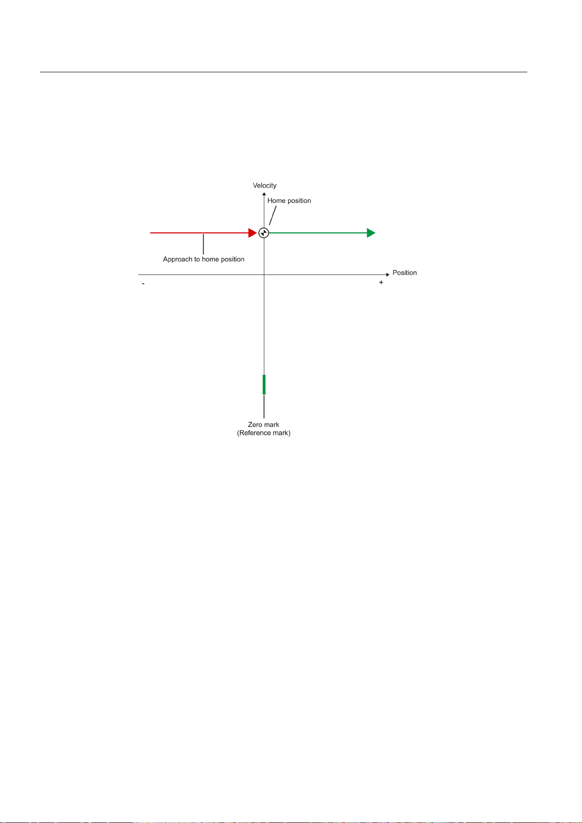
Basics
3.14.8
Passive homing with zero mark
3.14 Homing
The following figure shows an example of the homing motion with the following settings:
● Passive homing with zero mark
● Homing in the positive direction
S7-1500 Motion Control V13 Update 3
52 Function Manual, 07/2014, A5E03879256-AC
Page 53

Basics
Motion sequence
Enablement of passive homing via the Motion Control instruction "MC_Home".
Motion due to a Motion Control job from the application
Detection of the homing mark
Note
Parameter "MC_Home.Mode"
The "MC_Home.Mode" parameter for S7
Control has been standardized within the framework of technology version V2.0. This
results in a new assignment of the parameter values for the "MC_Home.Mode"
paramet
V1.0 and V2.0 is available in the section
3.14 Homing
The motion occurs in the following sequence:
1.
2.
The detection of the homing mark is enabled when the actual position value of the axis or
encoder moves in the assigned homing direction.
3.
When the homing mark is detected, the position of the axis or encoder is set depending
on the configured mode:
– Parameter "Mode" to "MC_Home" = 2, 8
Position = value in parameter "Position"
– Parameter "Mode" to "MC_Home" = 10
Position = value in tag <TO>.Homing.HomePosition
-1200 Motion Control and S7-1500 Motion
er. A comparison of the "MC_Home.Mode" parameter for technology versions
Version overview (Page 86).
S7-1500 Motion Control V13 Update 3
Function Manual, 07/2014, A5E03879256-AC
53
Page 54
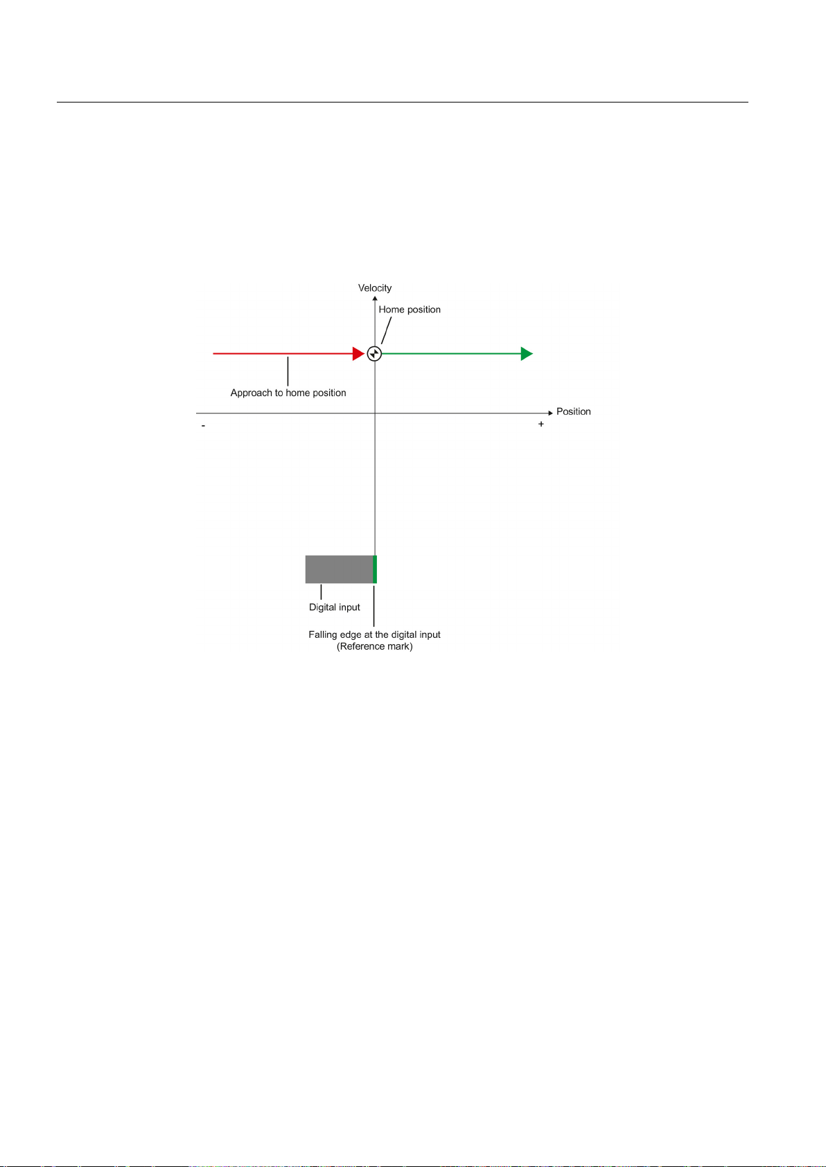
Basics
3.14.9
Passive homing with digital input
3.14 Homing
The following figure shows an example of the homing motion with the following settings:
● Passive homing with digital input
● Homing in the positive direction
● Homing mark on the positive side of the digital input
S7-1500 Motion Control V13 Update 3
54 Function Manual, 07/2014, A5E03879256-AC
Page 55

Basics
Motion sequence
Enablement of passive homing via the Motion Control instruction "MC_Home".
Motion due to a Motion Control job from the application
Detection of the homing mark
Note
Parameter "MC_Home.Mode"
The "MC_Home.Mode" parameter for S7
Control has been standardized within the framework of technology version V2.0. This
results in a new assignment of the parameter values for the "MC_Home.Mode"
parameter. A compariso
V1.0 and V2.0 is available in the section
3.14.10
Direction reversal at the hardware limit switch (reversing cam)
NOTICE
Avoid moving to a mechanical endstop
3.14 Homing
The motion occurs in the following sequence:
1.
2.
The detection of the homing mark at the digital input is enabled when the actual position
value of the axis or encoder moves in the assigned homing direction.
3.
In the example, the falling edge of the switch at the digital input represents the homing
mark.
When the homing mark is detected, the position of the axis or encoder is set depending
on the configured mode:
– Parameter "Mode" to "MC_Home" = 2, 8
Position = value in parameter "Position"
– Parameter "Mode" to "MC_Home" = 10
Position = value in tag <TO>.Homing.HomePosition
-1200 Motion Control and S7-1500 Motion
n of the "MC_Home.Mode" parameter for technology versions
Version overview (Page 86).
During active homing, the hardware limit switch can optionally be used as a reversing cam. If
the homing mark is not detected or the motion was not in the homing direction, then the
motion continues after the reversing cam in the opposite direction with the approach velocity.
When the hardware limit switch is reached, the dynamic defaults become effective.
Deceleration with the emergency stop deceleration does not occur.
Ensure by one of the following measures, that in a direction reversal the machine does not
move to a mechanical endstop.
• Keep the approach velocity low.
• Increase the configured acceleration / deceleration.
• Increase the offset between the hardware limit switch and the mechanical endstop.
S7-1500 Motion Control V13 Update 3
Function Manual, 07/2014, A5E03879256-AC
55
Page 56

Basics
3.14.11
Direct homing
Set position absolutely
Set position relatively
3.14.12
Absolute value adjustment
3.14 Homing
Depending on the configured mode, the position of the positioning axis/synchronous axis or
external encoder technology objects can be absolutely or relatively set with "MC_Home".
Proceed as follows to set the position absolutely:
1. In the Motion Control instruction "MC_Home", enter the absolute position in the "Position"
parameter.
2. Call the Motion Control instruction "MC_Home" with parameter "Mode" = 0.
The position is set to the value specified in the "Position" parameter.
Proceed as follows to set the position relatively:
1. In the Motion Control instruction "MC_Home", enter the relative position in the "Position"
parameter.
2. Call the Motion Control instruction "MC_Home" with parameter "Mode" = 1.
The position is set to the current position plus the value specified in the "Position" parameter.
In absolute value adjustment, Motion Control determines an absolute value offset, that is
retentively stored on the CPU.
Depending on the configured mode, the position of the axis or the encoder is absolutely or
relatively set in the "MC_Home" Motion Control instruction.
● Parameter "Mode" = 7 (absolute specification of position)
Position = value in parameter "Position"
● Parameter "Mode" = 6 (relative specification of position)
Position = current position + value in parameter "Position"
S7-1500 Motion Control V13 Update 3
56 Function Manual, 07/2014, A5E03879256-AC
Page 57

Basics
3.14.13
Resetting the "Homed" status
Incremental encoder
Note
Parameter "MC_Home.Mode"
The "MC_Home.Mode" parameter for S7
Control has been standardized within the framework of technology version V2.0. This
results in a new assignment of the parameter values for the "MC_Home.Mode"
parameter. A compariso
V1.0 and V2.0 is available in the section
Absolute value encoder
3.14 Homing
In the following cases, the "Homed" status is reset, and the technology object must be
rehomed.
● Errors in the sensor system / encoder failure
● Initiation of active homing with the Motion Control instruction "MC_Home" with
● Initiation of passive homing with the Motion Control instruction "MC_Home" with
"Mode" = 3, 5 (after successful completion of the homing process, the status "Homed" is
set again.)
-1200 Motion Control and S7-1500 Motion
n of the "MC_Home.Mode" parameter for technology versions
Version overview (Page 86).
"Mode" = 2, 8, 10 (after successful completion of the homing process, the status "Homed"
is set again.)
● Replacement of the CPU
● Replacement of the SIMATIC Memory Card
● POWER OFF
● Memory reset
● Modification of the encoder configuration
● Restart of the technology object
● Restoration of the CPU factory settings
● Transfer of a different project into the controller
In the following cases, the "Homed" status is reset, and the technology object must be
rehomed.
● Errors in the sensor system / encoder failure
● Replacement of the CPU
● Modification of the encoder configuration
● Restoration of the CPU factory settings
● Transfer of a different project into the controller
Resetting the memory of the CPU or upgrading a project does not require another absolute
value adjustment.
S7-1500 Motion Control V13 Update 3
Function Manual, 07/2014, A5E03879256-AC
57
Page 58
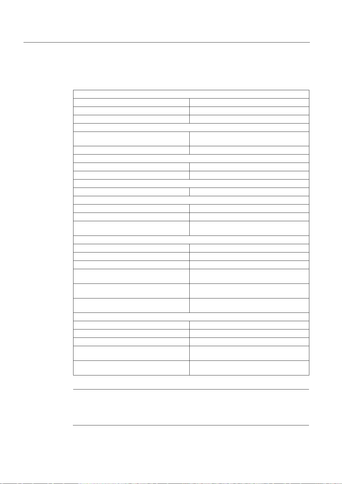
Basics
3.14.14
Tags
Status indicators
<TO>StatusWord.X11 (HomingCommand)
Homing command active
<TO>StatusWord.X5 (HomingDone)
Technology object is homed
<TO>ErrorWord.X10 (HomingFault)
Error occurred during homing
Approach to the proximity switch
proach to the proximity switch
<TO>.Homing.ApproachVelocity
Velocity for the approach to the proximity switch
Approach to the homing mark
<TO>.Sensor[n].ActiveHoming.Direction
Homing direction
<TO>.Homing.ReferencingVelocity
Velocity for the approach to the homing mark
Approach to home position
<TO>.Homing.ApproachVelocity
Velocity for the approach to the home position
Positions
<TO>.Homing.AutoReversal
Reversal at the hardware limit switches
<TO>.Homing.HomePosition
Home position
Parameters for active homing
<TO>.Sensor[n].ActiveHoming.Mode
Homing mode
<TO>.Sensor[n].ActiveHoming.SideInput
Side of the digital input
<TO>.Sensor[n].ActiveHoming.Direction
Homing direction or approach direction
Address
Number
Offset
Parameters for passive homing
<TO>.Sensor[n].PassiveHoming.Mode
Homing mode
<TO>.Sensor[n].PassiveHoming.SideInput
Side of the digital input
<TO>.Sensor[n].PassiveHoming.Direction
Homing direction or approach direction
Address
Number
Note
Evaluation of the bits in StatusWord, ErrorWord and WarningWord
Read the information provided in section Evaluate StatusWord, ErrorWord and WarningWord
(Page
3.14 Homing
The following technology object tags are relevant for homing:
<TO>.Homing.ApproachDirection Start direction or approach direction for the ap-
<TO>.StatusSensor[n].AbsEncoderOffset Calculated offset after the absolute value adjust-
ment
<TO>.Sensor[n].ActiveHoming.DigitalInput
<TO>.Sensor[n].ActiveHoming.DigitalInputBit
<TO>.Sensor[n].ActiveHoming.HomePosition
<TO>.Sensor[n].PassiveHoming.DigitalInput
<TO>.Sensor[n].PassiveHoming.DigitalInputBit
Byte number of the I/O address of the digital input
Bit number of the I/O address of the digital input
Offset of the homing mark from the home position
Byte number of the I/O address of the digital input
Bit number of the I/O address of the digital input
175).
S7-1500 Motion Control V13 Update 3
58 Function Manual, 07/2014, A5E03879256-AC
Page 59

Basics
3.15
Control
3.15.1
Brief description
Dynamic Servo Control (DSC)
See also
3.15 Control
The position controller of the positioning axis/synchronous axis is a closed-loop P controller
with pre-control of velocity.
If the drive supports Dynamic Servo Control (DSC), then a closed-loop position controller in
the drive can optionally be used.
In drives that support Dynamic Servo Control (DSC), you can optionally use the closed-loop
position controller in the drive. The position controller in the drive is usually implemented with
a rapid speed-control cycle. This improves the control performance for digitally coupled
drives. The communication times between controller and drive are automatically taken into
account.
For DSC, the drive's encoder must be used and standard message frame 5 must be set on
the drive.
Frames (Page 29)
S7-1500 Motion Control V13 Update 3
Function Manual, 07/2014, A5E03879256-AC
59
Page 60
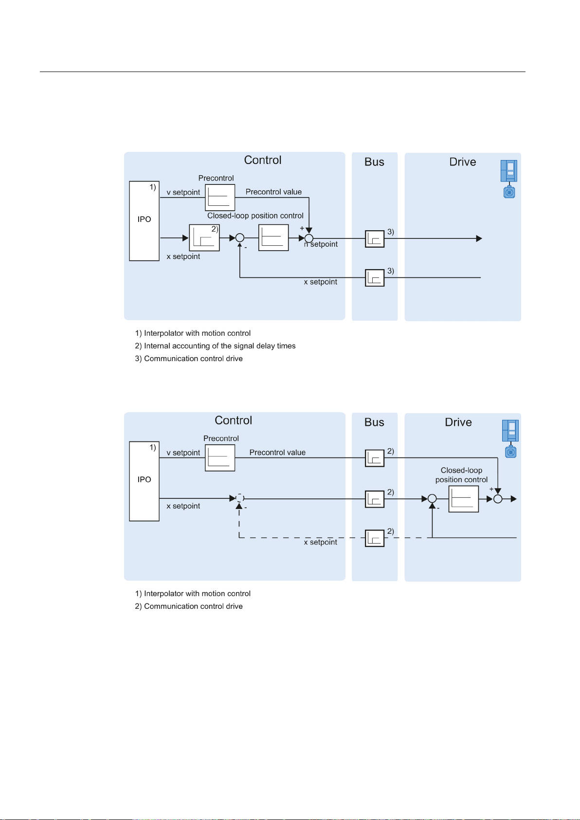
Basics
3.15.2
Control structure
3.15 Control
The following figure shows the effective control structure without DSC:
The following figure shows the effective control structure with DSC:
S7-1500 Motion Control V13 Update 3
60 Function Manual, 07/2014, A5E03879256-AC
Page 61

Basics
3.15.3
Tags
Parameter
<TO>.PositionControl.Kv
Proportional gain in the position control
<TO>.PositionControl.Kpc
Velocity pre-control in the position control (in %)
<TO>.PositionControl.EnableDSC
Enabling DSC
3.16
Position-related monitoring
3.16.1
Brief description
3.16 Position-related monitoring
The following technology object tags are relevant for control:
The following functions are available in the positioning axis/synchronous axis technology
object for monitoring positioning and motion:
● Positioning monitoring (Page 62)
The actual position value must reach a positioning window within a specified time, and
remain in this positioning window for a minimum dwell time.
● Following error monitoring (Page 63)
The following error is monitored based on a velocity-dependent following error limit. The
permissible maximum following error depends on the setpoint velocity.
If monitored conditions are violated, then technology alarms are output. The technology
object responds in accordance with the alarm response.
S7-1500 Motion Control V13 Update 3
Function Manual, 07/2014, A5E03879256-AC
61
Page 62
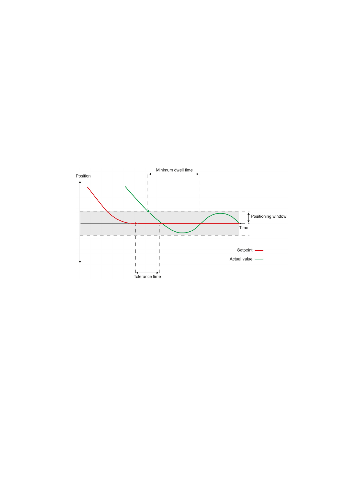
Basics
3.16.2
Positioning monitoring
Violation of positioning monitoring
3.16 Position-related monitoring
Positioning monitoring monitors the behavior of the actual position at the end of the setpoint
calculation.
As soon as the setpoint velocity reaches the value zero, the actual position value must be
located within a tolerance time in the positioning window. The setpoint must not exit the
positioning window during the minimum dwell time.
If the actual position value at the end of a positioning motion is reached within the tolerance
time and remains in the positioning window for the minimum dwell time, then
<TO>.StatusWord.X6 (Done) is set in the technology data block. This completes a Motion
Control job.
The following figure shows the chronological sequence and the positioning window:
Positioning monitoring does not make any distinction between how the setpoint interpolation
was completed. The end of setpoint interpolation can for example be reached as follows:
● by the setpoint reaching the target position
● by position controlled stopping during the motion, via the Motion Control instruction
"MC_Halt"
In the following cases, technology alarm 541 is output by the positioning monitoring, and the
technology object is disabled (alarm reaction: remove enable).
● The actual value does not reach the positioning window during the tolerance time.
● The actual value exits the positioning window during the minimum dwell time.
S7-1500 Motion Control V13 Update 3
62 Function Manual, 07/2014, A5E03879256-AC
Page 63

Basics
3.16.3
Following error monitoring
Calculation of the following error
Warning limit
Exceedance of the permissible following error
3.16 Position-related monitoring
The following error in the positioning axis/synchronous axis technology object is monitored
based on a velocity-dependent following error limit. The permissible following error depends
on the setpoint velocity.
A constant permissible following error can be specified for velocities less than an adjustable
velocity low limit.
Above this lower velocity limit, the permissible following error increases in proportion to the
setpoint velocity. The maximum permissible following error may be reached at the maximum
velocity.
The following error is the difference between the position setpoint and the actual position
value. The transmission times of the setpoint to the drive, and of the actual position value to
the controller, are taken into account in the calculation of the following error, i.e., subtracted
out.
A warning limit can be specified for the following error. The warning limit is input as a
percentage value and operates relative to the current permissible following error. If the
warning limit of the following error is reached, then technology alarm 522 is output. This is a
warning and contains no alarm response.
If the permissible following error is exceeded, then technology alarm 521 is output, and the
technology object is disabled (alarm response: remove enable).
S7-1500 Motion Control V13 Update 3
Function Manual, 07/2014, A5E03879256-AC
63
Page 64
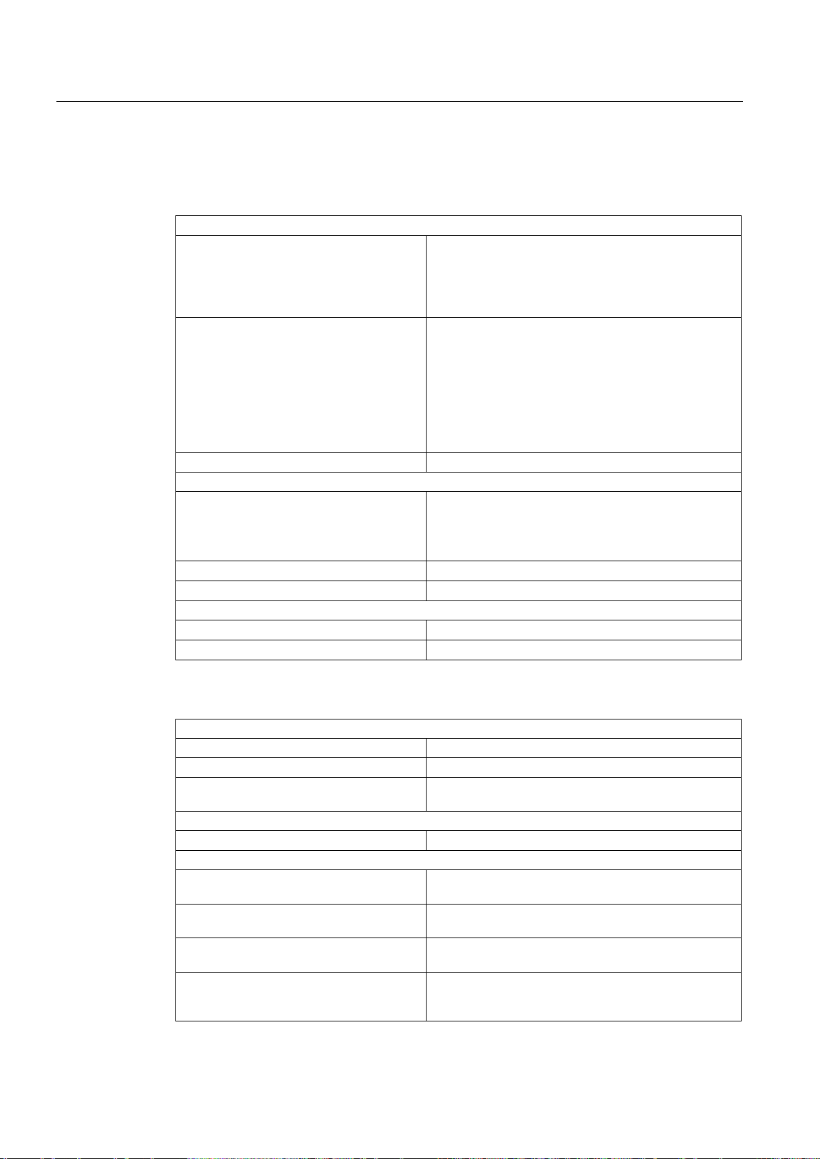
Basics
3.16.4
Tags
Status indicators
axis/synchronous axis.
Positioning axis/synchronous axis
Speed axis
the speed setpoint is equal to zero.
<TO>.ErrorWord.X12 (PositioningFault)
A positioning error has occurred.
Positions and times
lation.
<TO>.PositioningMonitoring.MinDwellTime
Minimum dwell time in the positioning window
<TO>.PositioningMonitoring.Window
Positioning window
Standstill signal
<TO>.StandstillSignal.MinDwellTime
Minimum dwell time below the velocity threshold
Status indicators
<TO>.StatusPositioning.FollowingError
Current following error
<TO>.ErrorWord.X11 (FollowingErrorFault)
Status indication, that the following error is too large
Warning)
has been reached
Control bits
<TO>.FollowingError.EnableMonitoring
Enabling / disabling following error monitoring
Limit values
the maximum following error
<TO>.FollowingError.MinVelocity
velocity
dependent in accordance with the characteristic curve)
3.16 Position-related monitoring
The following technology object tags are relevant for positioning monitoring:
<TO>.StatusWord.X7 (Standstill) Is set to the value TRUE , when the actual velocity
value goes below the velocity threshold, and does not
exit it within the minimum dwell time.
The standstill signal is only present at the positioning
<TO>.StatusWord.X6 (Done)
<TO>.PositioningMonitoring.ToleranceTime
Is set to the value TRUE, when the actual velocity value reaches the positioning window within the tolerance
time, and remains for the minimum dwell time in the
window.
Is set to TRUE, when the motion is completed and thus
Maximum permissible time until positioning window is
reached
The time is started with the end of the setpoint interpo-
<TO>.StandstillSignal.VelocityThreshold
Velocity threshold for the standstill signal
The following technology object tags are relevant for following error monitoring:
<TO>.WarningWord.X11 (FollowingError-
<TO>.FollowingError.MinVelocity Lower setpoint velocity for the characteristic curve of
<TO>.FollowingError.MinValue Permissible following error below the
<TO>.FollowingError.MaxValue Maximum permissible following error at maximum axis
<TO>.FollowingError.WarningLevel Warning limit as a percentage value relative to the
Status indication, that the following error warning limit
maximum permissible following error (velocity-
S7-1500 Motion Control V13 Update 3
64 Function Manual, 07/2014, A5E03879256-AC
Page 65
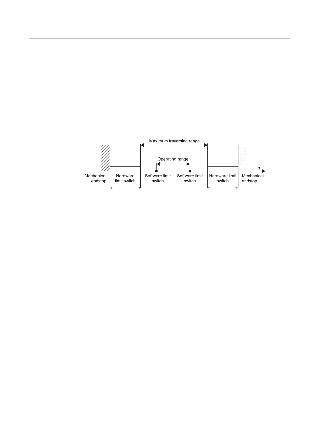
Basics
3.17
Traversing range limitation
3.17.1
Brief description
3.17.2
Hardware limit switches
Approaching the hardware limit switches
Exception
3.17 Traversing range limitation
Hardware and software limit switches limit the permissible traversing range and operating
range of the positioning axis/synchronous axis. Before use, they must be enabled in the
configuration or in the user program.
The following figure shows the relationship between operating range, maximum traversing
range and the limit switches:
Hardware limit switches are limit position switches that limit the maximum permissible
traversing range of the axis.
Select the positions of the hardware limit switches so that there is adequate braking distance
for the axis when needed. The axis should come to a standstill before a mechanical endstop.
In the monitoring of range limitation, no distinction is made, whether the switches are
approached or overshot.
If a hardware limit switch is approached, technology alarm 531 is output, and the technology
object is disabled (alarm response: remove enable).
If the hardware limit switches are used as reversing cams or reference cams, then the
monitoring of the hardware limit switches has no effect.
S7-1500 Motion Control V13 Update 3
Function Manual, 07/2014, A5E03879256-AC
65
Page 66
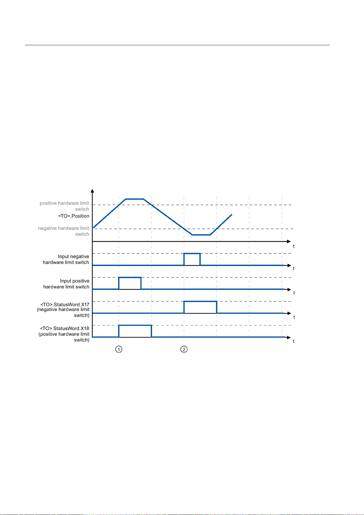
Basics
Retracting
3.17 Traversing range limitation
The position of the axis when the hardware limit switch is detected is stored internally on the
CPU. The status of the approached hardware limit switch is reset only after the hardware
limit switch is left and the axis is once again in the maximum traversing range.
To be able to traverse the axis again after reaching the hardware limit switch and to reset the
status of the hardware limit switch, follow the steps below:
1. To allow movement away from the limit switch, acknowledge the technology alarm.
2. Traverse the axis away from the hardware limit switch until it leaves it.
The axis must then be within the maximum traversing range.
If you traverse the axis in the direction of the limit switch before the axis has left it, the
monitoring will be triggered again.
The following diagram shows the response of the status word when reaching the hardware
limit switch and when releasing the axis again:
Figure 3-1 Status message HW-ES
At the time ① the position of the axis when the positive hardware limit switch is detected is
stored internally on the CPU. To reset the status of the hardware limit switch, the axis must
be pulled back from this position.
At the time
② the position of the axis when the negative hardware limit switch is detected is
stored internally on the CPU. To reset the status of the hardware limit switch, the axis must
pass this position.
S7-1500 Motion Control V13 Update 3
66 Function Manual, 07/2014, A5E03879256-AC
Page 67

Basics
3.17.3
Software limit switch
Modulo enabled
Approaching the software limit switches
Overshooting the software limit switches
Retracting
3.17 Traversing range limitation
The operating range of the axis is limited with software limit switches. Relative to the
traversing range, always position the software limit switches within the hardware limit
switches. Since the positions of the software limit switches can be flexibly configured, the
operating range of the axis can be individually adapted in accordance with the current
velocity profile.
Software limit switches are only effective when there is a valid actual value after homing the
technology object. The monitoring of the software limit switches is relative to the setpoint.
With modulo enabled, the modulo position is monitored.
The software limit switches are enabled or disabled using the tags in the technology data
block. If the positions of both software limit switches are outside the modulo range, then the
monitoring has no effect. It is not checked, whether the positions of the software limit
switches are within the modulo range.
At the beginning of a positioning motion, it is not checked, whether the software limit
switches will be approached by approaching the specified target position.
If the software limit switches are approached, then technology alarm 533 is output, and the
axis is stopped with the maximum dynamic values (alarm response: Stop with maximum
dynamic values). The technology object remains enabled.
If a software limit switch is overshot, technology alarm 534 is output, and the technology
object is disabled (alarm response: remove enable).
Proceed as follows to retract the axis after violation of the software limit switch:
1. Acknowledge the technology alarm.
2. Move the axis in the free travel direction, until the software limit switch is exited.
If you move opposite to the free travel direction before exiting the software limit switch,
then the monitor with be triggered again.
S7-1500 Motion Control V13 Update 3
Function Manual, 07/2014, A5E03879256-AC
67
Page 68
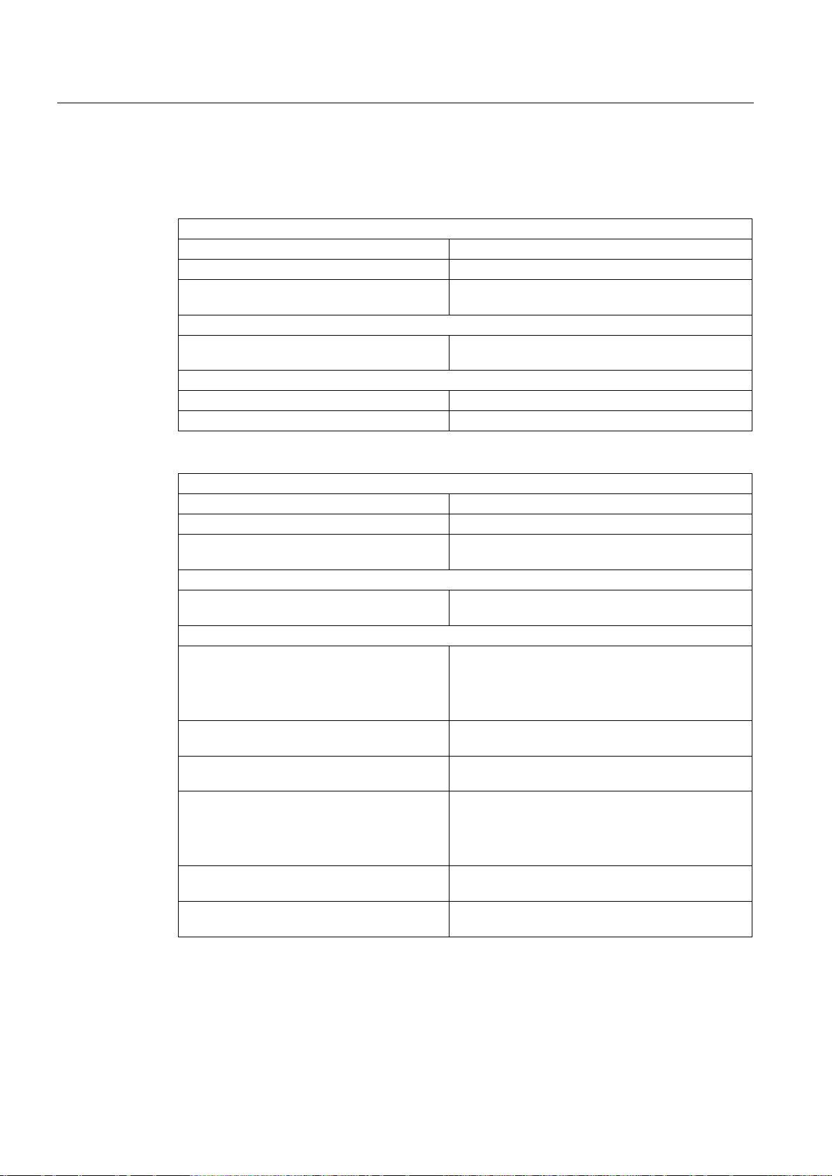
Basics
3.17.4
Tags
Status indicators
<TO>.StatusWord.X15 (SWLimitMinActive)
Negative software limit switch is enabled
<TO>.StatusWord.X16 (SWLimitMaxActive)
Positive software limit switch is enabled
violated
Control bits
limit switches
Position values
<TO>.PositonLimits_SW.MinPosition
Position of the negative software limit switch
<TO>.PositonLimits_SW.MaxPosition
Position of the positive software limit switch
Status indicators
<TO>.StatusWord.X17 (HWLimitMinActive)
Negative hardware limit switch is enabled
<TO>.StatusWord.X18 (HWLimitMaxActive)
Positive hardware limit switch is enabled
Control bits
Parameter
TRUE: At high level, the signal is enabled
switch for the lower or minimum position
switch for the lower or minimum position
TRUE: At high level, the signal is enabled
switch for the upper or maximum position
switch for the upper or maximum position
3.17 Traversing range limitation
The following technology object tags are relevant for software limit switches:
<TO>.ErrorWord.X8 (SWLimit) An alarm is pending, that a software limit switch was
<TO>.PositonLimits_SW.Active Enables / disables the monitoring of the software
The following technology object tags are relevant for hardware limit switches:
<TO>.ErrorWord.X9 (HWLimit) An alarm is queued; a hardware limit switch was
violated
<TO>.PositonLimits_HW.Active Enables / disables the monitoring of the hardware
limit switches
<TO>.PositonLimits_HW.MinSwitchLevel Level selection for enablement of the lower hard-
ware limit switch:
FALSE: At low level, the signal is enabled
<TO>.PositonLimits_HW.MinSwitchAddress Byte number of the I/O address of the hardware limit
<TO>.PositonLimits_HW.MinSwitchBitNumber Bit number of the I/O address of the hardware limit
<TO>.PositonLimits_HW.MaxSwitchLevel Level selection for enablement of the upper hard-
ware limit switch:
FALSE: At low level, the signal is enabled
<TO>.PositonLimits_HW.MaxSwitchAddress Byte number of the I/O address of the hardware limit
<TO>.PositonLimits_HW.MaxSwitchBitNumber Bit number of the I/O address of the hardware limit
S7-1500 Motion Control V13 Update 3
68 Function Manual, 07/2014, A5E03879256-AC
Page 69

Basics
3.18
Motion control and limits for dynamics
3.18.1
Brief description
3.18 Motion control and limits for dynamics
Motion control of the axis occurs by means of velocity profiles (Page 70). The velocity
profiles are calculated in accordance with the specifications for dynamics. A velocity profile
defines the behavior of the axis during approach, braking and changes in velocity. During
positioning a velocity profile is calculated, that moves the axis to the target point.
Maximum values for velocity, acceleration and jerk result from the properties of the drive and
the mechanics. These maximum values can be configured in the limits for dynamics. The
limits for dynamics are in effect as limits for every motion generated by means of the
technology object.
The configurable emergency stop deceleration (Page 71) is triggered by the Motion Control
instruction MC_Power or by a technology alarm.
The jerk limit reduces the mechanical load during an acceleration ramp or deceleration ramp.
A "smoothed" velocity profile results.
S7-1500 Motion Control V13 Update 3
Function Manual, 07/2014, A5E03879256-AC
69
Page 70
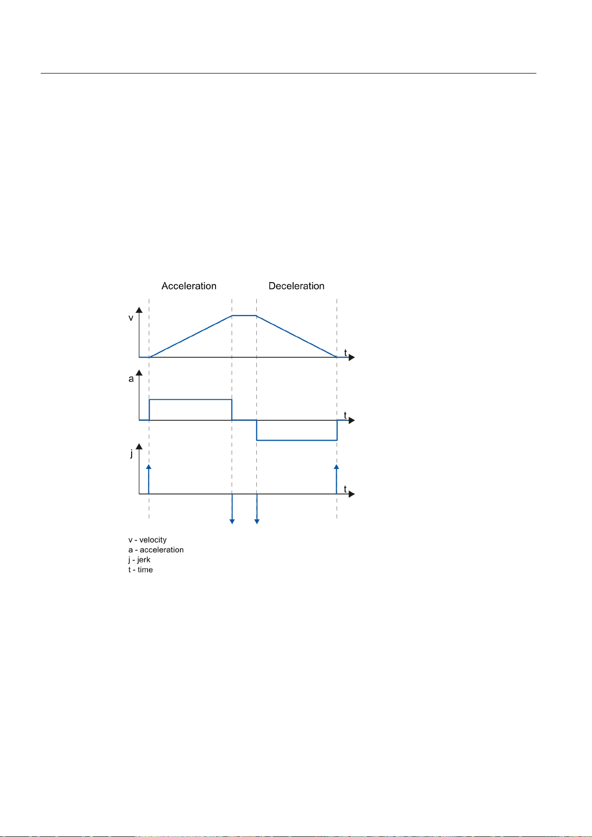
Basics
3.18.2
Velocity profile
Velocity profile without jerk limit
3.18 Motion control and limits for dynamics
A velocity profile without jerk limit and a velocity profile with jerk limit are both supported for
Motion Control of the axis.
The dynamic values for the motion are specified in the Motion Control job. Alternatively the
dynamic default values can be used. The defaults and the limits for velocity, acceleration,
deceleration and jerk are set in the configuration.
To influence velocity, a velocity override can override the current traversing velocity.
The following figure shows velocity, acceleration and jerk:
S7-1500 Motion Control V13 Update 3
70 Function Manual, 07/2014, A5E03879256-AC
Page 71
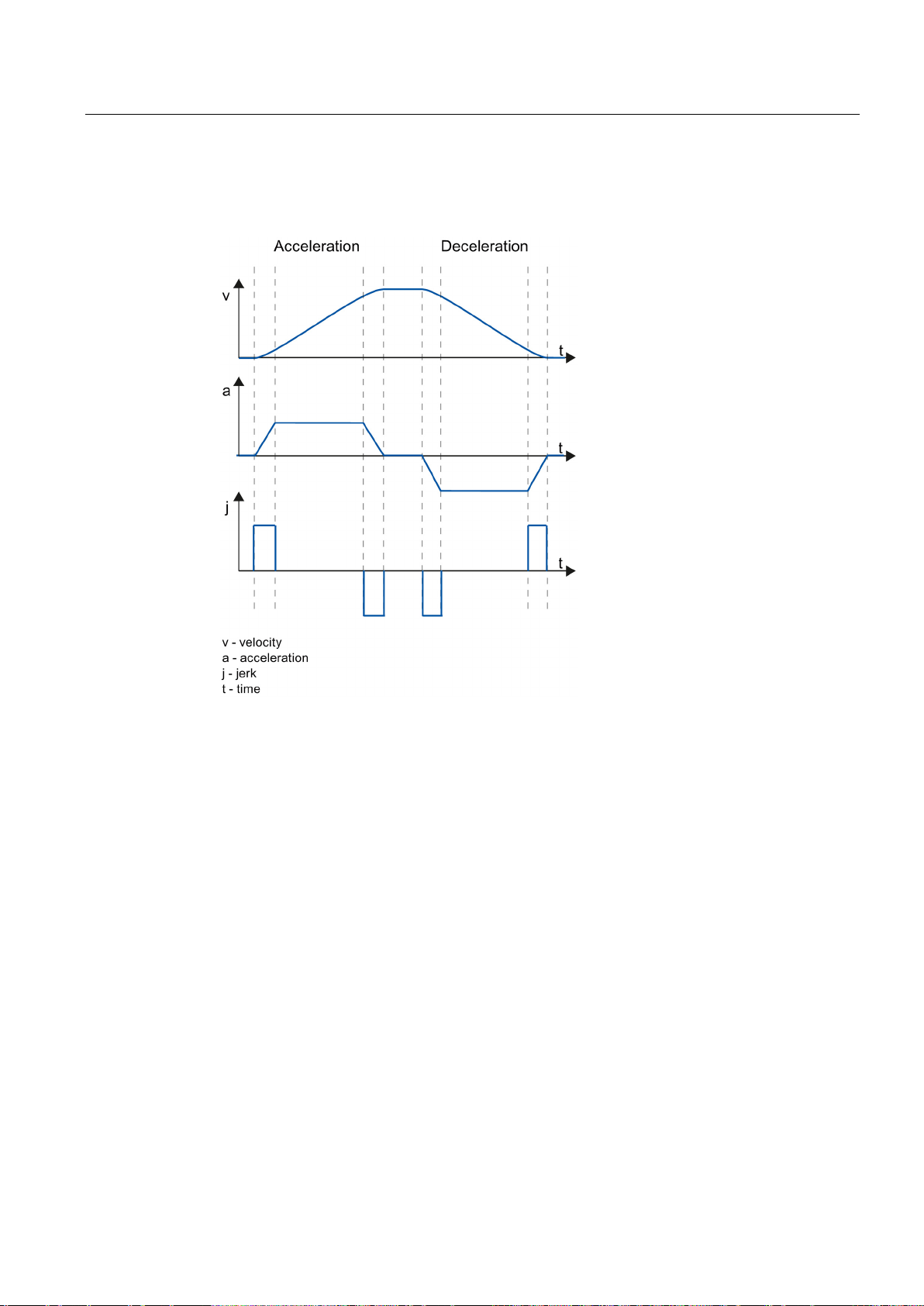
Basics
Velocity profile with jerk limit
3.18.3
Emergency stop deceleration
3.18 Motion control and limits for dynamics
The following figure shows velocity, acceleration and jerk:
A velocity profile with jerk limit is employed for a continuous acceleration and deceleration
sequence. The jerk can be specified.
When stopping with the emergency stop ramp, the axis is braked to a standstill without a jerk
limit, using the configured emergency stop deceleration.
In the following cases the configured emergency stop deceleration is in effect:
● For an emergency stop ramp that has been enabled via the Motion Control instruction
"MC_Power" with parameter "StopMode" = 0.
● For a technology alarm with the local alarm response "Stop with emergency stop ramp".
This emergency stop deceleration can be set greater than the maximum deceleration. If the
emergency stop deceleration is set lower than this, it may occur that the axis does not stop
until after the limit switch in the case of "Stop at software limit switch" and the occurrence of
a technology alarm with the local alarm response "Stop with emergency stop ramp".
S7-1500 Motion Control V13 Update 3
Function Manual, 07/2014, A5E03879256-AC
71
Page 72

Basics
3.18.4
Tags
Status
<TO>.StatusWord
Status indicators for an active motion
<TO>.Position
Setpoint position
<TO>.Velocity
Setpoint velocity / setpoint speed
<TO>.ActualPosition
Actual position
<TO>.ActualVelocity
Actual velocity
(with analog setpoint = 0.0)
<TO>.Acceleration
Setpoint acceleration
<TO>.ActualAcceleration
Actual acceleration
Override
<TO>.Override.Velocity
Velocity override
Dynamic limit values
<TO>.DynamicLimits.MaxVelocity
Dynamic limit for maximum velocity
<TO>.DynamicLimits.MaxAcceleration
Dynamic limit for maximum acceleration
<TO>.DynamicLimits.MaxDeceleration
Dynamic limit for maximum deceleration
Defaults for the dynamics
<TO>.DynamicDefaults.Velocity
Default velocity
<TO>.DynamicDefaults.Acceleration
Default acceleration
<TO>.DynamicDefaults. Deceleration
Default deceleration
<TO>.DynamicDefaults.Jerk
Default jerk
EmergencyDeceleration
3.18 Motion control and limits for dynamics
The following technology object tags are relevant for motion control:
<TO>.ActualSpeed Actual speed of the motor
<TO>.DynamicLimits.MaxJerk Dynamic limit for maximum jerk
<TO>.DynamicDefaults.
S7-1500 Motion Control V13 Update 3
Emergency stop deceleration
72 Function Manual, 07/2014, A5E03879256-AC
Page 73
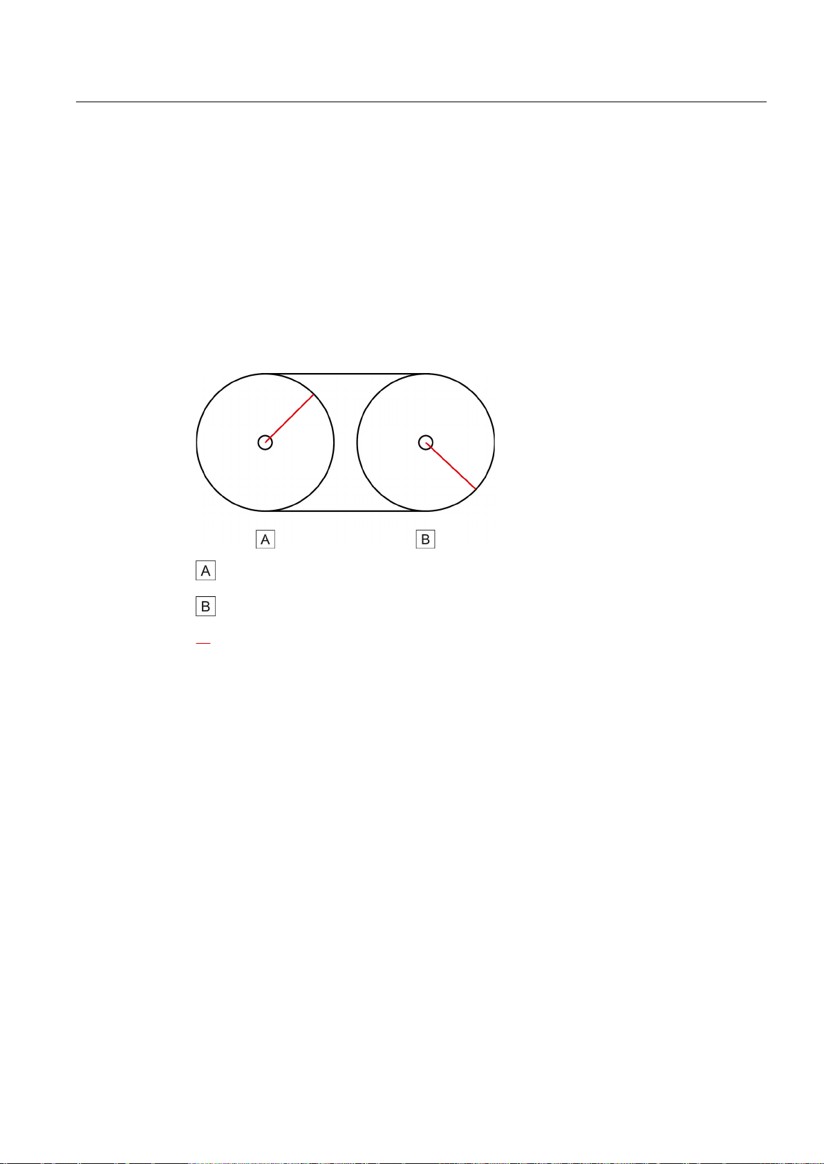
Basics
3.19
Synchronous operation
3.19.1
Brief description
Relative position relationship
3.19 Synchronous operation
The functionality of relative gearing is provided by the synchronous axis technology object.
The change of the leading axis position setpoint is multiplied by a specified gear ratio and
passed on to the following axis as change in the position setpoint.
The relative gearing couples a following axis to a leading axis as if the axes were connected
via a mechanical transmission.
Leading axis (driven axis)
Following axis
The following axis is synchronized to the leading axis by means of the Motion Control
instruction "MC_GearIn", which represents the mechanical transmission in this case. An
active synchronous operation is overridden by motion jobs on the following axis.
S7-1500 Motion Control V13 Update 3
Function Manual, 07/2014, A5E03879256-AC
73
Page 74

Basics
3.19.2
Relative gearing
Synchronization
3.19 Synchronous operation
The gear ratio is specified as the relationship between two integers at the Motion Control
instruction "MC_GearIn". The result is a linear transmission function. With relative gearing,
there is a relative correlation between the leading axis and the following axis. The change of
the leading axis position setpoint results from the change in the position setpoint of the
leading axis multiplied by the gear ratio.
Synchronization is begins by starting an "MC_GearIn" job. When a synchronous axis
synchronizes to a master value, it is displayed in the tag of the <TO>.StatusWord.X21
(Synchronizing) technology object. Active motion jobs are overridden. The dynamic values
(acceleration, delay, jerk) of the following axis for the synchronization are specified at
"MC_GearIn".
The following axis is synchronized and moves synchronously to the leading axis when the
following axis reaches the velocity and acceleration of the leading axis, taking the gear ratio
into consideration.
Duration and length of synchronization depend on the dynamic of the leading axis and the
dynamic defaults at "MC_GearIn". A position offset can result between leading axis and
following axis. This position offset is not compensated.
S7-1500 Motion Control V13 Update 3
74 Function Manual, 07/2014, A5E03879256-AC
Page 75
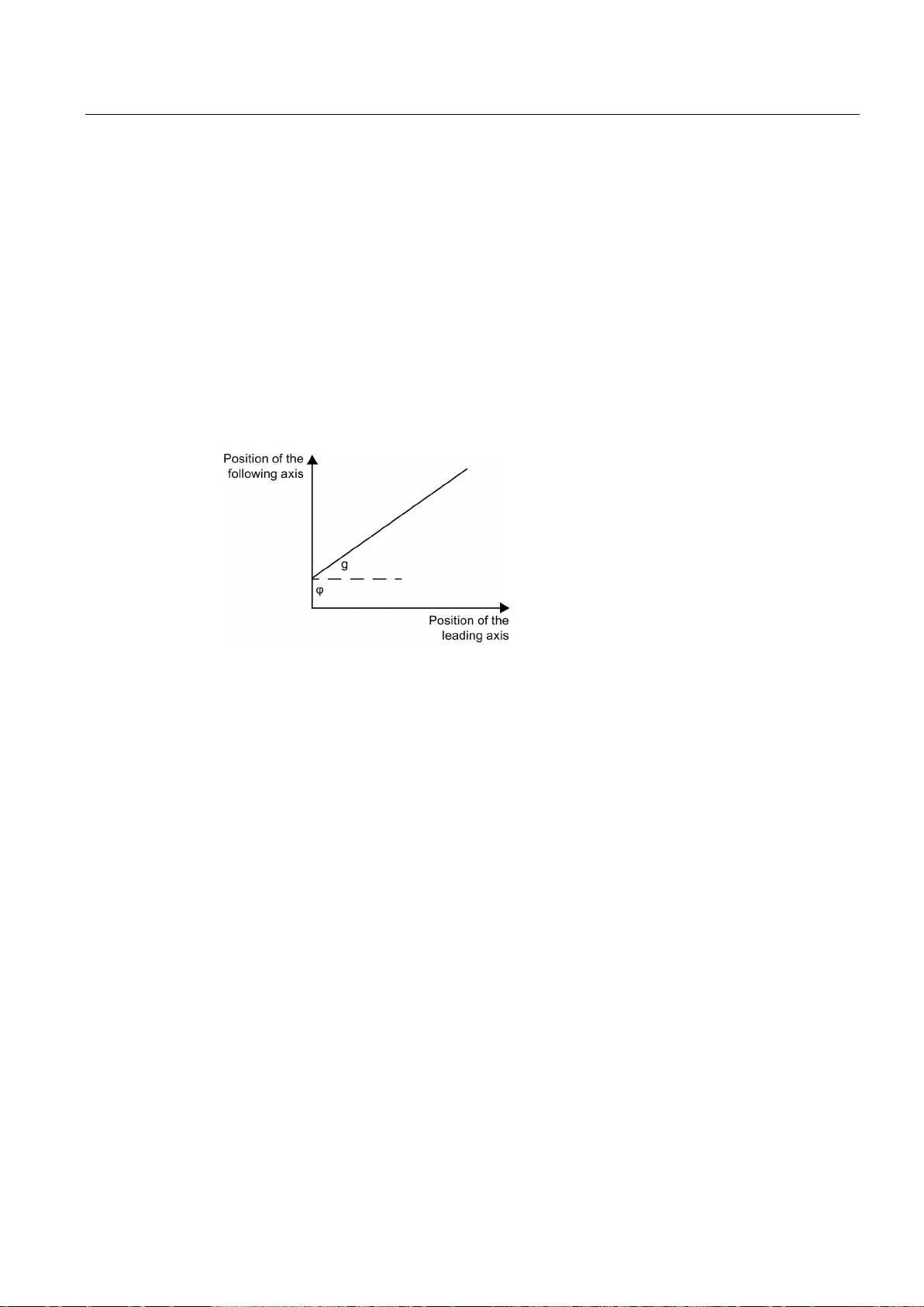
Basics
Synchronous motion
g
Gear ratio (transformation ratio)
The position offset is derived from the synchronization and is constant thereafter.
Overriding synchronous operation
Direction
Positive gear ratio:
Negative gear ratio
3.19 Synchronous operation
When a synchronous axis is synchronized to a master value, the "synchronous" status is
displayed by the parameter "MC_GearIn.InGear" = TRUE as well as in the tag of the
<TO>.StatusWord.X22 (Synchronous) technology object. The following axis follows the
dynamics of the leading axis according to the gear ratio.
The dynamic limits configured on the following axis are no longer in effect in the
"synchronous" state. The speed setpoint output to the drive is limited to the configured
maximum speed of the drive (<TO>.Actor.DriveParameter.MaxSpeed).
If the following axis cannot follow the master value, a following error occurs which is
monitored by the following error monitoring.
The response characteristic of gearing is expressed as a linear correlation between the
master value and the slave value.
φ Position offset between master value and slave value in synchronous operation
The slave value is calculated according to the following formula:
Slave value = g × master value + φ
An active synchronous operation is overridden by motion jobs on the following axis.
The numerator of the gear ratio is specified as positive or negative. This results in the
following response:
●
The leading and following axes move in the same direction.
●
The following axis rotates in the opposite direction of the leading axis.
:
S7-1500 Motion Control V13 Update 3
Function Manual, 07/2014, A5E03879256-AC
75
Page 76
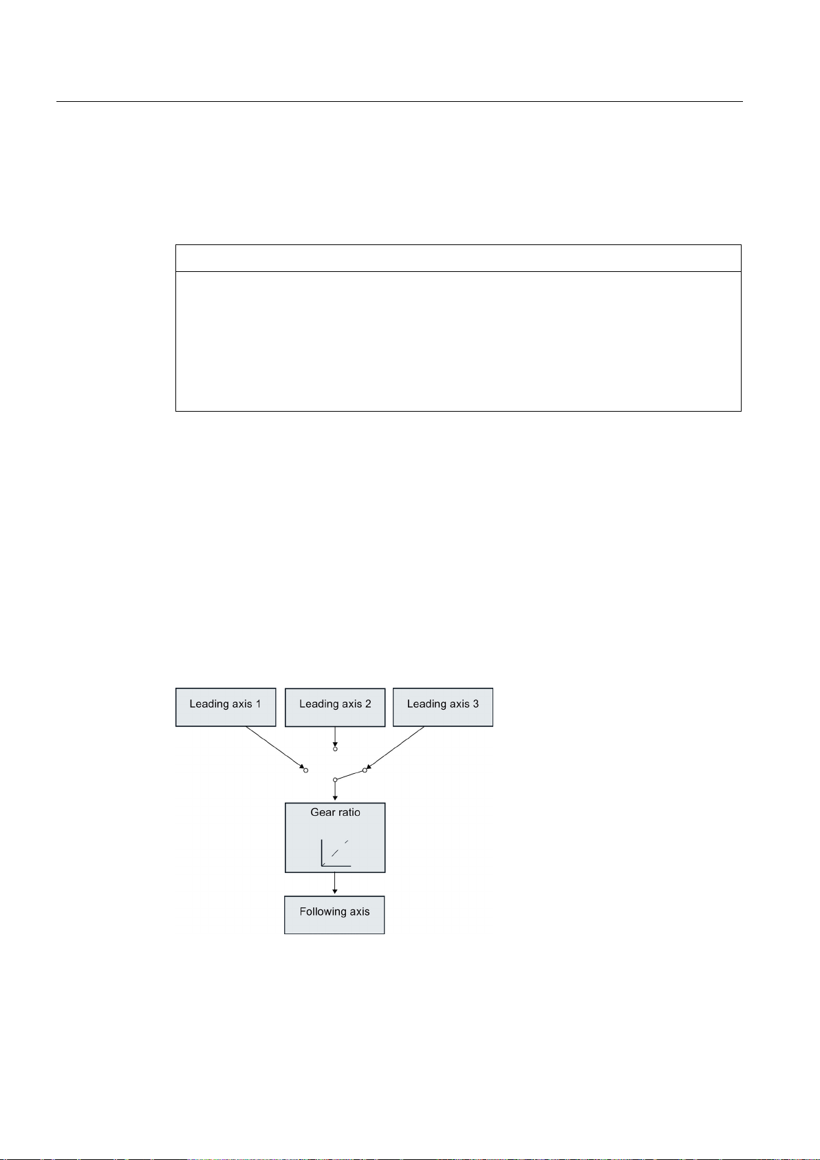
Basics
Homing with active synchronous operation
NOTICE
Drive damage
3.19.3
Master value coupling
3.19 Synchronous operation
A position offset at the following axis is not compensated with relative gearing. This means a
new offset results when homing the following axis during an active synchronous operation. A
job for active homing at a following axis overrides synchronous operation.
The position of the leading axis can change suddenly during homing of the leading axis.
This master value jump has the effect of a setpoint jump at the following axis. The setpoint
jump is traversed at the following axis taking the gear ratio into consideration. Jerky
compensation motions at the following axis and drive damage could result.
If homing of the leading axis is required during active synchronous operation, keep the
master value jump and its effects on the following axis to a minimum.
The master value for synchronous operation is provided by a leading axis. The master
values are always the position setpoints of the leading axis (setpoint coupling). A following
axis can be coupled with different master values. Only one master value is actively evaluated
at any one time. The master value can be specified by positioning axes or synchronous
axes.
The master value is specified in the user program with the call of the Motion Control
instruction "MC_GearIn". The master value is switched when you call the "MC_GearIn" again
specifying a different leading axis.
The figure below shows an example of a synchronous axis with several master values:
S7-1500 Motion Control V13 Update 3
76 Function Manual, 07/2014, A5E03879256-AC
Page 77
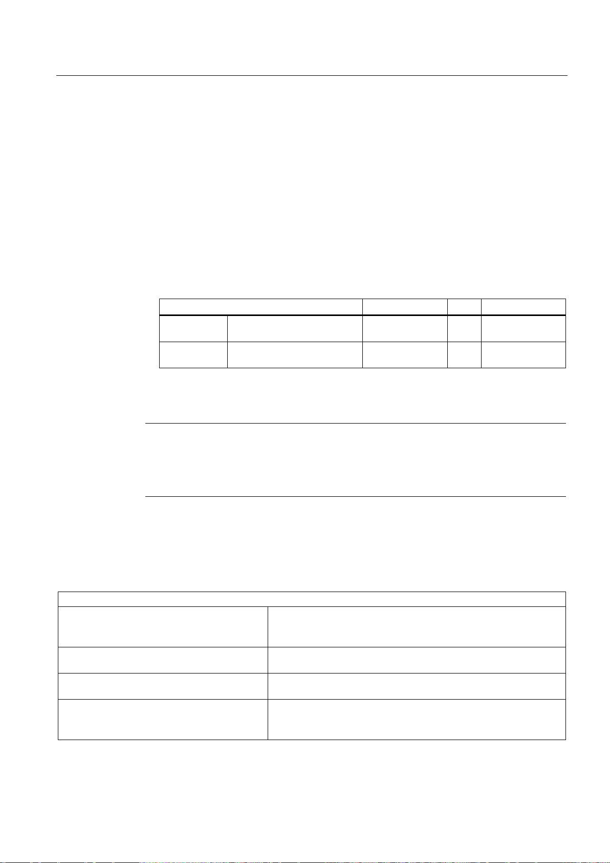
Basics
Interconnection
Axis 1
Axis 2
axis for axis 2
for axis 1
Note
The master values and slave values are
configured user unit. If the leading axis is a linear axis (millimeters) and the following axis is
a rotary axis (degrees), for example, the unit is not converted during synchronous operation.
If the leading axi
3.19.4
Tags
Status indicators
"ActiveMaster" = 0 with disabled synchronous operation
to the leading axis, the value is set to TRUE .
"MC_GearIn" was not configured as a possible leading axis.
3.19 Synchronous operation
The following rules apply to the master value coupling:
● Positioning axes and synchronous axes can specify master values. A leading axis can
output the master value to several following axes.
● The synchronous axis can be interconnected with different master values. All
interconnections required during operation must be set up during configuration of the
synchronous axis technology object.
● Only one master value is actively evaluated at any one time.
● Recursive interconnections are not possible. A leading axis cannot be interconnected as
following axis to its own master value.
The following example shows a recursive interconnection that is not permitted:
The following interconnections are configured in the TIA Portal:
A Axis 1 is a possible leading
B Axis 2 is possible leading axis
Leading axis → Following axis
Following axis ← Leading axis
Use the Motion Control instruction "MC_GearIn" to enable interconnection A or
interconnection B. Interconnections A and B cannot be enabled at the same time
because it would be a recursive interconnection.
coupled without conversion into the relevant
s moves by 10 mm, the following axis moves by 10° with a gear ratio of 1:1.
The following technology object tags are relevant for synchronous operation:
<TO>.StatusSynchronizedMotion.ActualMaster When a "MC_GearIn" job is started, the number of the technology data
block of the currently used leading axis is displayed.
<TO>.StatusWord.X21 (Synchronizing) When the synchronous axis synchronizes to a master value, the value
is set to TRUE.
<TO>.StatusWord.X22 (Synchronous) When the synchronous axis is synchronized and moves synchronously
<TO>.ErrorWord.X14 (SynchronousError) Error during synchronous operation
The leading axis specified at the Motion Control instruction
S7-1500 Motion Control V13 Update 3
Function Manual, 07/2014, A5E03879256-AC
77
Page 78

Basics
3.20
Operational sequence
3.20.1
Organization Blocks for Motion Control
Description
MC-Servo [OB91]
MC-Interpolator [OB92]
3.20 Operational sequence
When you create a technology object, organization blocks are automatically created for
processing the technology objects. The Motion Control functionality of the technology objects
creates its own execution level, and is called according to the Motion Control application
cycle.
The following blocks are created:
●
Calculation of the Position Controller
●
Evaluation of the motion control instructions, generation of setpoints and monitoring
functionality
The organization blocks are protected (know-how protection). The program code cannot be
viewed or changed.
The frequency relationship of the two organization blocks to one another is always 1:1.
MC-Servo [OB91] is always executed before MC-Interpolator [OB92].
You can set the application cycle and the priority of the organization blocks according to your
requirements for control quality and system load.
S7-1500 Motion Control V13 Update 3
78 Function Manual, 07/2014, A5E03879256-AC
Page 79

Basics
Application cycle
Synchronous to the bus
Cyclic
Clock reduction (CPU V1.5 and higher)
Priority
MC Servo [OB91]
MC Interpolator [OB92]
3.20 Operational sequence
You can set the application cycle in which the MC-Servo [OB91] is called in the properties of
the organization block in "General > Cycle Time":
●
MC-Servo [OB91] is called synchronously with or at a reduced ratio to a bus system. You
set the send clock in the properties of the selected bus system. In the "Distributed I/O"
drop-down list, you can select the following bus systems:
– Isochronous PROFIBUS DP
– Isochronous PROFINET IO
You cannot call the MC-Servo [OB91] synchronously with a bus system that is connected
to the CPU via a communications processor/communications module (CP/CM).
●
The MC-Servo [OB91] is called cyclically with the specified application cycle.
The selected application cycle must be long enough to be able to process the technology
objects in one cycle. If the processing time of the technology objects is longer than the
application cycle, overflows (Page 80) will occur.
You can check the runtime of MC-Servo [OB91] and MC-Interpolator [OB92] with the
expanded instruction "RT_INFO".
You can reduce the application cycle of the MC-Servo [OB91] relative to the send clock of an
isochronous PROFINET IO system. You can set an integer multiple of the send clock as the
factor. Values up to 14 times the send clock (maximum 32 ms) are possible for the
application cycle.
If you call a isochronous interrupt OB and the MC-Servo [OB91] synchronously with the
same PROFINET IO system, set the same application cycle for both organization blocks.
You can configure the priority of the organization blocks as needed in their properties under
"General > Properties > Priority":
●
Priority 17 to 31 (default value 25)
●
Priority 16 to 30 (default value 24)
The priority of MC Servo [OB91] must be at least one higher than the priority of the
MC Interpolator [OB92].
S7-1500 Motion Control V13 Update 3
Function Manual, 07/2014, A5E03879256-AC
79
Page 80
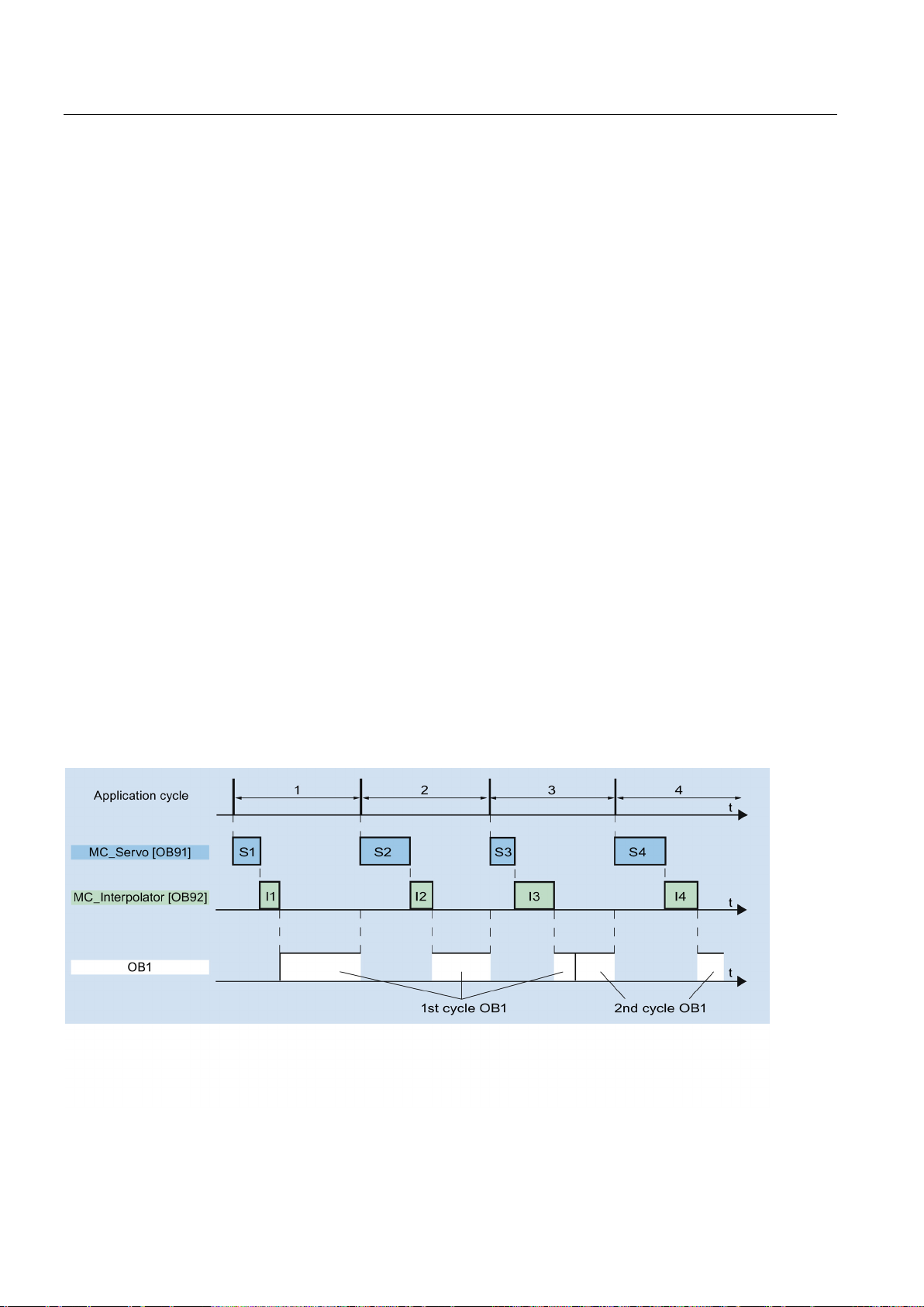
Basics
3.20.2
Process image partition "OB Servo PIP"
Process image partition in the user program
3.20.3
Operational Sequence and Timeouts
3.20 Operational sequence
The process image partition "OB Servo PIP" is made available in isochronous mode for
Motion Control. All drives and encoders used by Motion Control are assigned to this process
image partition.
Additionally, you should assign all I/O modules used by Motion Control to this process image
partition (e.g. hardware limit switches). The assignment results in chronologically
synchronous processing with the technology object.
The input process image partition is also updated in STOP mode.
As of CPU version V1.5, you can access the process image partition "TPA OB Servo" in your
user program. This makes it possible to evaluate the process image partition using the trace
and logic analyzer function.
When processing the motion control functionality, the organization blocks MC-Servo [OB91]
and MC-Interpolator [OB92] are called and processed in each application cycle. The
remaining cycle time is available for the processing of your user program.
For error-free program execution, keep to the following rules:
● In each application cycle, MC-Servo [OB91] must be started and executed completely.
● In every application cycle, the relevant MC-Interpolator [OB92] must at least be started.
The following figure shows an example of the error-free operational sequence for the
processing of organization block OB1:
S7-1500 Motion Control V13 Update 3
80 Function Manual, 07/2014, A5E03879256-AC
Page 81
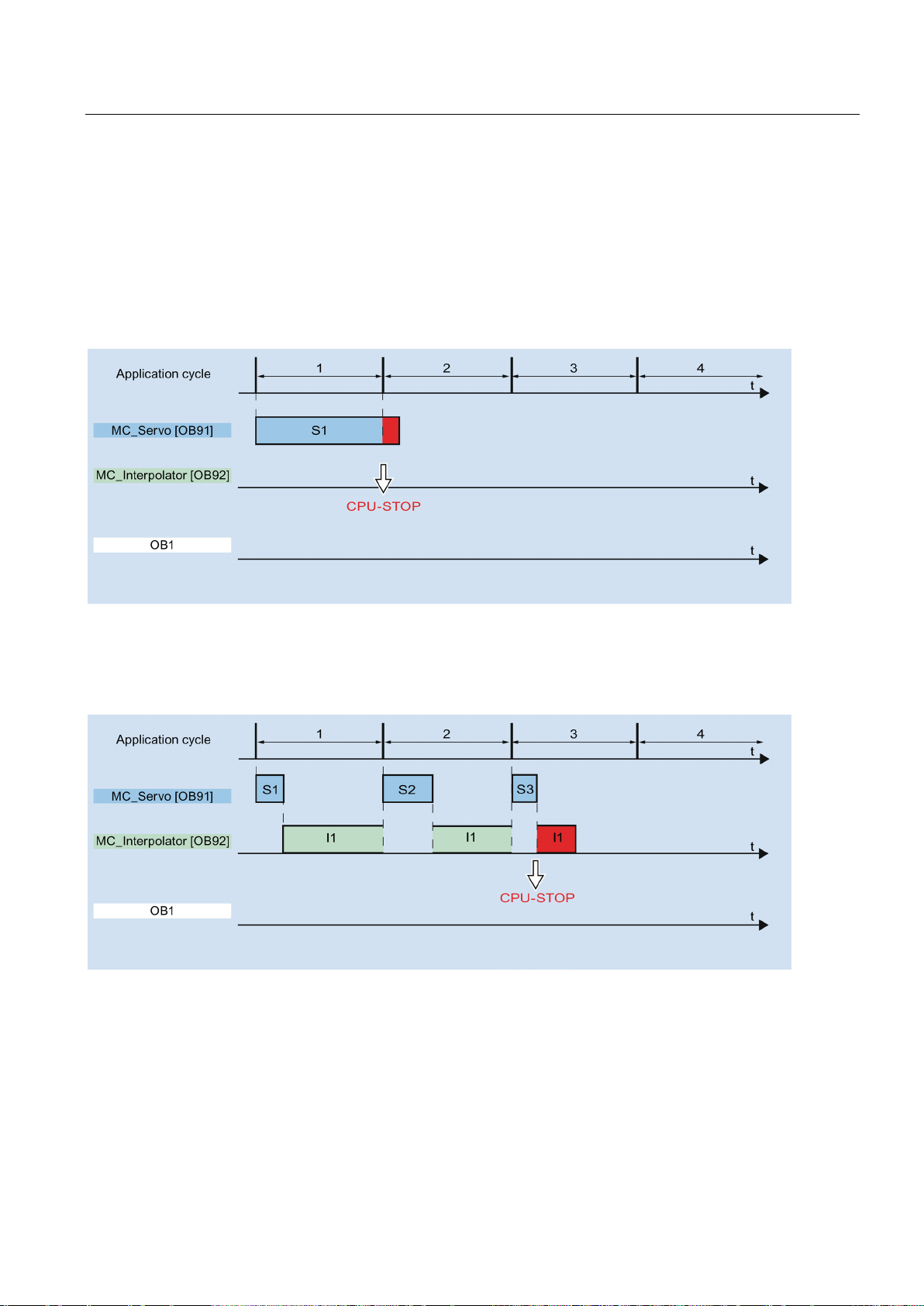
Basics
Overflows
3.20 Operational sequence
If the set application cycle is not adhered to, for example because the application cycle is too
short, overflows can occur.
The CPU will not tolerate overflow of MC-Servo [OB91]. An overflow will cause the CPU to
change to STOP mode.
The following figure shows the operational sequence if there is an overflow of MC-Servo
[OB91]:
The execution of an MC-Interpolator [OB92] may only be interrupted by an MC-Servo [OB91]
call. If more interruptions occur, the CPU switches to STOP mode.
The following figure shows the sequence when an MC-Interpolator [OB92] is interrupted over
two time slices:
S7-1500 Motion Control V13 Update 3
Function Manual, 07/2014, A5E03879256-AC
81
Page 82
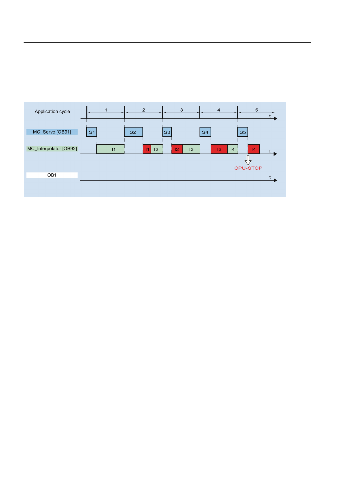
Basics
3.20 Operational sequence
The CPU tolerates a maximum of three consecutive overflows of MC-Interpolator [OB92]. If
more overflows occur, the CPU switches to STOP mode.
The following figure shows the sequence if there are four consecutive individual overflows of
MC-Interpolator [OB92]:
S7-1500 Motion Control V13 Update 3
82 Function Manual, 07/2014, A5E03879256-AC
Page 83
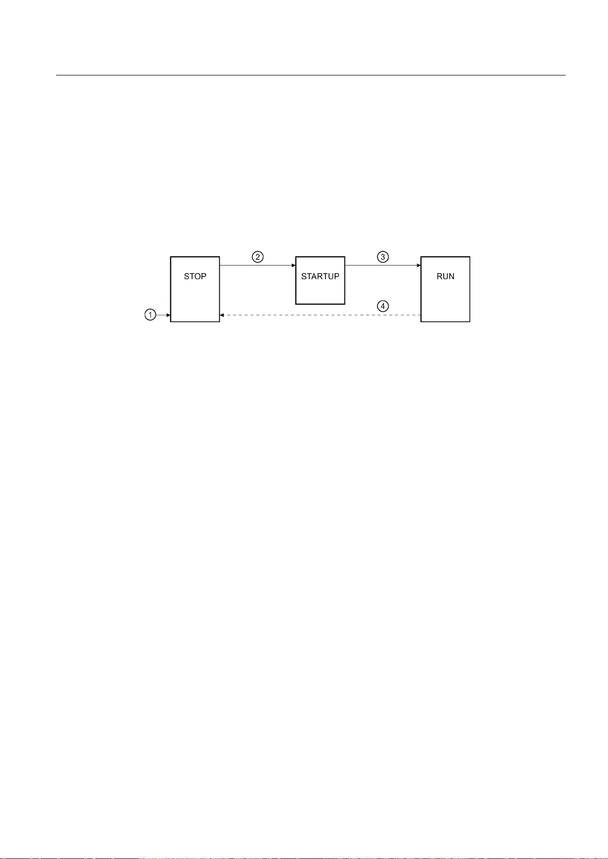
Basics
3.20.4
Operating modes
Operating modes and transitions
STOP mode
STARTUP mode
RUN mode
3.20 Operational sequence
This section examines the behavior of Motion Control in each operating mode, and in the
transitions between operating modes. A general description of the operating modes can be
found in system manual S7-1500.
The CPU has three operating modes: STOP, STARTUP and RUN. The following figure
shows the operating modes and the operating mode transitions:
In STOP mode the user program is not processed and al process outputs are disabled. Thus
no Motion Control jobs are executed.
The technology data blocks are updated.
Before the CPU starts processing of the cyclical user program, the startup OBs are
processed one time.
In STARTUP mode, the process outputs are disabled. Motion Control jobs are rejected.
The technology data blocks are updated.
The user program is processed in RUN mode.
In RUN mode, the programmed Motion Control jobs are cyclically called and processed.
The technology data blocks are updated.
S7-1500 Motion Control V13 Update 3
Function Manual, 07/2014, A5E03879256-AC
83
Page 84
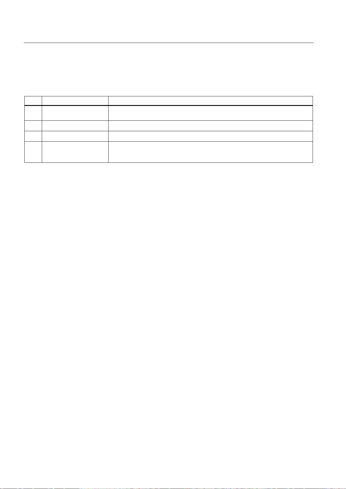
Basics
Operating mode transitions
No.
Operating mode transition
Behavior
reinitialized with the values from the load memory.
②
③
④
tion Control jobs are terminated.
3.20 Operational sequence
The following table shows the behavior of Motion Control in the transitions between the
operating modes:
①
POWER ON → STOP The CPU performs a restart of the technology objects. The technology objects are
STOP → STARTUP Not relevant to Motion Control.
STARTUP → RUN The process outputs are enabled.
RUN → STOP When the CPU changes to RUN mode after STOP mode, all technology objects are
disabled in accordance with the alarm response "remove enablement". Running Mo-
S7-1500 Motion Control V13 Update 3
84 Function Manual, 07/2014, A5E03879256-AC
Page 85

4
4.1
Guidelines on use of motion control
Requirements
Procedure
The guidelines described here present the basic procedure for using Motion Control with the
CPU S7-1500. These guidelines serve as recommendations.
● A project with a CPU S7-1500 has been created.
Proceed as follows to use Motion Control with the CPU S7-1500:
1. Add technology object (Page 99)
2. Working with the configuration editor (Page 100)
3. Programming (Page 172)
4. Downloading to CPU (Page 198)
5. Functional test in the Commissioning window (Page 199)
6. Diagnostics (Page 214)
S7-1500 Motion Control V13 Update 3
Function Manual, 07/2014, A5E03879256-AC
85
Page 86

5
5.1
Overview of versions
The technology version for S7-1500 Motion Control includes the version of the technology
objects and the version of the Motion Control instructions. Only one technology version can
be operated on a CPU. This means that operation of two different technology versions sideby-side is not possible on one CPU.
When changing to a CPU V1.6, you must change the technology version to V2.0. Card
replacement from a CPU < V1.6 to a CPU V1.6 is not permitted. In the TIA Portal, you can
only work on projects with technology version V2.0 with a CPU V1.6.
There are two ways of changing the technology version:
● Changing the version of the Motion Control instructions
You change the version of the Motion Control instructions in the "Instructions" task card in
the folder "Technology > Motion Control > S7-1500 Motion Control".
If the Motion Control instruction version used does not correspond to the compatibility list,
the relevant Motion Control instructions are highlighted in red in the program editor.
● Adding a technology object with an alternative version
If a technology object with an alternative version is added in the "Add new object" dialog,
the technology version is changed to the alternative version.
The technology objects and Motion Control instructions are only converted to the selected
version of the technology during compilation.
The version of a technology object or a Motion Control instruction can be checked in the
object properties in the "General > Information" tab in the "Version" box.
S7-1500 Motion Control V13 Update 3
86 Function Manual, 07/2014, A5E03879256-AC
Page 87

Using versions
Compatibility list
CPU
Technology
Technology object
Motion Control Instruction
MC_Reset V1.0
V2.0
1) Card replacement from a CPU < V1.6 to a CPU V1.6 is not supported.
5.1 Overview of versions
The table below shows the compatibility of the technology version with the CPU version:
V1.0, V1.1,
V1.51
V1.6
V1.0 Speed axis V1.0
Innovations:
• Synchronous axis
• Relative gearing
• MC_GearIn
• MC_MoveSuperimposed
• Standardization of the
"MC_Home.Mode" parameter for
S7-1200 Motion Control and
S7-1500 Motion Control
• Simulation mode
• Support of the safety functions of the
drive
Positioning axis V1.0
External encoder V1.0
Speed axis V2.0
Positioning axis V2.0
External encoder V2.0
Synchronous axis V2.0
MC_Power V1.0
MC_Home V1.0
MC_MoveJog V1.0
MC_MoveVelocity V1.0
MC_MoveRelative V1.0
MC_MoveAbsolute V1.0
MC_Halt V1.0
MC_Power V2.0
MC_Home V2.0
MC_MoveJog V2.0
MC_MoveVelocity V2.0
MC_MoveRelative V2.0
MC_MoveAbsolute V2.0
MC_Halt V2.0
MC_Reset V2.0
MC_GearIn V2.0
MC_MoveSuperimposed V2.0
S7-1500 Motion Control V13 Update 3
Function Manual, 07/2014, A5E03879256-AC
87
Page 88
Using versions
Parameter "Mode" of the Motion Control instruction "MC_Home"
MC_Home.HomingMode V1.0
Parameter value
MC_Home.Mode V2.0
Direct homing (absolute)
0
Direct homing (absolute)
Direct homing (relative)
1
Direct homing (relative)
Passive homing
2
Passive homing (without reset)
Passive homing (with configured home position)
3
Active homing
Active homing
4
Reserved
Active homing (with configured home position)
5
Active homing (with configured home position)
Absolute encoder adjustment (relative)
6
Absolute encoder adjustment (relative)
Absolute encoder adjustment (absolute)
7
Absolute encoder adjustment (absolute)
Passive homing (without reset)
8
Passive homing
Canceling passive homing
9
Canceling passive homing
-
10
Passive homing (with configured home position)
5.1 Overview of versions
The "MC_Home.Mode" parameter for S7-1200 Motion Control and S7-1500 Motion Control
has been standardized within the framework of technology version V2.0. This results in a
new assignment of the parameter values for the "MC_Home.Mode" parameter.
The table below shows a comparison of the "MC_Home.Mode" parameter for technology
V1.0 and V2.0:
You can find additional information about the "MC_Home.Mode" parameter in the description
of the Motion Control instruction "MC_Home" (Page 239).
S7-1500 Motion Control V13 Update 3
88 Function Manual, 07/2014, A5E03879256-AC
Page 89

Using versions
5.2
Changing a technology version
Changing technology version to V2.0
5.2 Changing a technology version
Before you can access all the benefits of a new technology version, you need to change the
technology version for existing projects.
To change the technology version to V2.0, follow these steps:
1. Replace the CPU V1.0...V1.5 in the project with a CPU V1.6.
2. Open the programming editor (e.g., by opening the OB1).
The technology objects and Motion Control instructions are highlighted in red after the
CPU is replaced.
3. In the "Instructions" task card, open the technology version V2.0 in the
"Technology > Motion Control > S7-1500 Motion Control" folder.
4. Save and compile the project.
The version of the technology objects and Motion Control instructions is changed to V2.0
during compilation of the project.
Pay attention to any error information that is displayed during compilation. Deal with the
causes of the errors indicated.
5. Check the configuration of the technology objects.
S7-1500 Motion Control V13 Update 3
Function Manual, 07/2014, A5E03879256-AC
89
Page 90

Using versions
Resetting the parameter "Mode" of the Motion Control instruction "MC_Home"
5.2 Changing a technology version
When the technology version is changed from V1.0 to V2.0, the "MC_Home.HomingMode"
(V1.0) parameter is renamed to "MC_Home.Mode" (V2.0). The assignment of the parameter
values is changed as well.
To reset the "MC_Home.Mode" (V2.0) parameter, follow these steps:
1. To change the technology version, follow the instructions given above.
When compiling the project, the "MC_Home.HomingMode" (V1.0) parameter is renamed
to "MC_Home.Mode" (V2.0):
– The assignment of the parameter values is changed. A comparison of the
"MC_Home.Mode" parameter for technology versions V1.0 and V2.0 is available in the
section Version overview (Page 86).
You can find additional information about the "MC_Home.Mode" parameter in the
description of the Motion Control instruction "MC_Home" (Page 239).
– The value configured at the "MC_Home.HomingMode" parameter (V1.0) is lost. As a
note on renaming, the following text is entered at the "MC_Home.Mode" (V2.0)
parameter as parameter value:
"Die Schnittstelle hat sich geändert. Weitere Informationen finden Sie in der
Beschreibung der Motion Control-Anweisung MC_Home."
– There is a message in the "Info > Compile" tab in the Inspector window stating that the
operand has the wrong data type.
2. Change the value of the "MC_Home.Mode" parameter (V2.0) in your user program
according to the new assignment.
3. Save and compile the project.
S7-1500 Motion Control V13 Update 3
90 Function Manual, 07/2014, A5E03879256-AC
Page 91

6
6.1
Adding and configuring drives in the device configuration
6.1.1
Add and configure PROFINET IO drives
SINAMICS S120
drive
Requirements
Adding a drive and frame in the device configuration
Adding and configuring a PROFINET IO drive is described below using a
. Adding and configuring other PROFINET IO drives may differ from the description in
certain respects.
● The SIMATIC S7-1500 device is created in the project.
● The desired drive can be selected in the hardware catalog.
If the drive is not available in the Hardware Catalog, then it must be installed in the "Extras"
menu as a device description file (GSD).
1. Open the device configuration and change to the network view.
2. In the hardware catalog, open the folder "Additional Field Devices > PROFINET IO >
Drives > Siemens AG > SINAMICS".
3. Select the desired drive with the desired version, then drag it to the network view.
4. Assign the drive to the PROFINET interface of the PLC.
5. Open the drive in the device view.
6. Drag a Drive Object (DO) and a standard frame from the hardware catalog to the slot of
the device overview of the drive.
Depending on the version of the SINAMICS S120 drive, select "DO with standard telegram
X", or "DO Servo" and a "Standard telegram X" for the frame.
For more information on suitable frames, refer to the section Frames (Page 29).
Repeat step 6, if you want to add another drive and another standard frame.
S7-1500 Motion Control V13 Update 3
Function Manual, 07/2014, A5E03879256-AC
91
Page 92

Configuring
Enable isochronous operation of the drive in the device configuration
Interconnecting the port of the PLC with the port of the drive
Configuring the PLC as the sync master and setting isochronous mode
Select drive in the configuration of the technology object
Result
6.1 Adding and configuring drives in the device configuration
PROFINET drives can always be operated in isochronous mode or non-isochronous mode.
Isochronous mode, however, increases the quality of the position control of the drive.
Proceed as follows if you want to control the drive in isochronous mode:
1. Open the device view in the drive.
2. In the properties dialog, select the tab "PROFINET Interface [X1] > Advanced options >
Isochronous mode".
3. Select the "Isochronous mode" check box in this tab.
The entry for the frame also has to be selected for isochronous mode in the detailed view.
1. Open the topology view in the device configuration.
2. Interconnect the port of the PLC with the port of the drive.
1. Select the device view of the PLC.
2. In the properties dialog, select the tab "PROFINET Interface [X1] > Advanced options >
Realtime settings > Synchronization".
3. Select "Sync master" from the "Synchronization role" drop-down list.
4. Click the "Domain settings" button.
5. Open the "Domain Management > Sync Domains" tab and set the desired "Send clock"
(isochronous clock).
1. Add a new axis technology object, or open the configuration of an existing axis.
2. Open the configuration "Hardware interface > Drive".
3. Select "PROFIdrive" from the "Drive type" drop-down list.
4. Select the Drive Object of the PROFINET drive from the "Drive" list.
For information on how to add a technology object, refer to the section Add technology
object (Page 99).
The technology object is connected to the drive and the "MC Servo" organization block can
be checked / configured.
The frame of the configured drive is assigned to the "PIP OB Servo" process image.
S7-1500 Motion Control V13 Update 3
92 Function Manual, 07/2014, A5E03879256-AC
Page 93

Configuring
Checking/configuring the properties of the MC Servo
Result
Checking isochronous mode on the drive
See also
6.1 Adding and configuring drives in the device configuration
1. Open the "Program blocks" folder in the project navigator.
2. Select the "MC Servo" organization block.
3. Select the "Properties" command in the shortcut menu.
4. Select the "Cycle time" entry in the area navigation.
5. The option "Synchronous to the bus" must be selected in the dialog box.
6. A "PROFINET IO_System" must be selected in the "Distributed I/O" drop-down list.
7. The application cycle of "MC-Servo" must correspond to the send clock of the bus or be
reduced by an integral factor relative to the send clock of the bus.
The PROFINET IO drive is now configured so that it can be controlled in the PROFINET IO
network in isochronous mode.
The properties of the SINAMICS drive must be configured according to the configuration of
the axis with a separate STARTER program.
If the configuration sequence described above is not adhered to during configuration of the
axis, and drive-specific error occurs when the project is compiled, the setting for isochronous
mode on the drive must be checked.
1. Open the device view in the drive.
2. Select standard message item in the device overview.
3. Select the properties dialog "General > I/O Addresses".
4. The following settings apply for the input and output addresses:
– "Isochronous mode" is enabled.
– "MC Servo" must be select the "Organization block".
– "PIP OB Servo" must be select the "Process image".
Frames (Page 29)
Add technology object (Page 99)
S7-1500 Motion Control V13 Update 3
Function Manual, 07/2014, A5E03879256-AC
93
Page 94

Configuring
6.1.2
Add and configure PROFIBUS DP drives
SINAMICS S120
Requirements
Adding a drive and frame in the device configuration
Enable isochronous operation of the drive in the device configuration
6.1 Adding and configuring drives in the device configuration
Adding and configuring a PROFIBUS IO drive is described below using a
Adding and configuring other PROFIBUS drives may differ from the description in certain
respects.
● The SIMATIC S7-1500 device is created in the project.
● You have a basic knowledge of how to configure PROFIBUS DP networks.
● The desired drive can be selected in the hardware catalog.
If the drive is not available in the Hardware Catalog, then it must be installed in the "Extras"
menu as a device description file (GSD).
1. Open the device configuration and change to the network view.
2. In the hardware catalog, open the folder "Additional Field Devices > PROFIBUS DP >
Drives > Siemens AG > SINAMICS".
3. Select the folder of the desired drive with the desired version, then drag the drive object
to the network view.
4. Assign the drive to the PROFIBUS interface of the PLC.
.
5. Open the drive in the device view.
6. Drag a standard frame from the hardware catalog to the slot of the device overview of the
drive.
For more information on suitable frames, refer to the section Frames (Page 29).
Use the "Axis disconnector" in the hardware catalog if you want to add another drive and
another standard frame in the device overview.
PROFIBUS drives can always be operated in cyclic mode or isochronous mode. Isochronous
mode, however, increases the quality of the position control of the drive.
Proceed as follows if you want to control the drive in isochronous mode:
1. Open the device view in the drive.
2. In the properties dialog, select the tab "General > Isochronous Mode".
3. Select the "Synchronize DP slave to constant DP bus cycle time" check box .
S7-1500 Motion Control V13 Update 3
94 Function Manual, 07/2014, A5E03879256-AC
Page 95

Configuring
Setting isochronous mode
Select drive in the configuration of the technology object
Result
Checking/configuring the properties of the MC Servo
Result
6.1 Adding and configuring drives in the device configuration
1. Select the network view.
2. Select the DP master system.
3. In the properties dialog, select the tab "General > Constant bus cycle time".
4. Select the desired "Constant DP bus cycle times".
1. Add a new axis technology object, or open the configuration of an existing axis.
2. Open the configuration "Hardware interface > Drive".
3. Select "PROFIdrive" from the "Drive type" drop-down list.
4. Select the standard frame of the PROFIBUS drive from the "Drive" list.
For information on how to add a technology object, refer to the section Add technology
object (Page 99).
The technology object is connected to the drive and the "MC Servo" organization block can
be checked/configured.
The frame of the configured drive is assigned to the "PIP OB Servo" process image.
1. Open the "Program blocks" folder in the project navigator.
2. Select the "MC Servo" organization block.
3. Select the "Properties" command in the shortcut menu.
4. Select the "Cycle time" entry in the area navigation.
5. The option "Synchronous to the bus" must be selected in the dialog box.
6. A "PROFINET IO system" must be selected in the "Distributed I/O" drop-down list.
7. The application cycle of "MC-Servo" must correspond to the send clock of the bus or be
reduced by an integral factor relative to the send clock of the bus.
You can select a drive connected to the CPU via a communications
processor/communications module (CP/CM) in the configuration of the technology object.
You cannot select the DP master system of the CP/CM as the source clock for MC-Servo
[OB91].
The PROFIBUS DP drive is now configured so that it can be controlled in the PROFIBUS
network in isochronous mode.
The properties of the SINAMICS drive must be configured according to the configuration of
the axis with a separate STARTER program.
S7-1500 Motion Control V13 Update 3
Function Manual, 07/2014, A5E03879256-AC
95
Page 96

Configuring
Checking isochronous mode on the drive
See also
6.1.3
Adding and configuring drives with analog connections
Requirements
Adding and configuring an analog output module in the device configuration
6.1 Adding and configuring drives in the device configuration
If the configuration sequence described above is not adhered to during configuration of the
axis, and drive-specific error occurs when the project is compiled, isochronous mode can be
checked on the drive.
1. Open the device view in the drive.
2. Select standard message item in the device overview.
3. Select the properties dialog "General > I/O Addresses".
4. The following settings apply for the input and output addresses:
– "MC Servo" must be select the "Organization block".
– "PIP OB Servo" must be select the "Process image".
Add technology object (Page 99)
Frames (Page 29)
A description is provided below of how to add and configure a drive with an analog drive
connection and an encoder. An incremental encoder and a technology module in the rack of
the PLC is used as an example of the connection.
The SIMATIC S7-1500 device is created in the project.
1. Open the device configuration of the PLC.
2. Select an analog output module from the hardware catalog and drag the module to the
rack of the PLC.
3. Select the analog output module in the device view.
4. Open the "General" tab in the properties dialog and select there "Name of the Analog
Output Module > I/O Addresses".
5. Enter the desired start address.
6. In the properties dialog, select the tab "General > IO Tags".
7. Enter the tag name for the desired analog output.
S7-1500 Motion Control V13 Update 3
96 Function Manual, 07/2014, A5E03879256-AC
Page 97

Configuring
Adding and configuring a technology module
Selecting the drive and encoder in the configuration of the technology object
Result
6.1 Adding and configuring drives in the device configuration
1. Switch to the device view of the PLC.
2. In the hardware catalog, open the folder "TM > Count > TM Count 2X24V".
3. Drag the counter module to a free slot in the rack.
4. Select the technology module in the device view.
5. In the properties dialog, open the "General" tab and select there "Count 2x24V > Basic
Parameters > Channel X > Operating Mode" of the channel to be used.
6. Select "Position detection for motion control" option for "Selection of the operating mode
for the channel".
7. Under "Module parameters", adapt the parameters of the incremental encoder (steps per
revolution = increments per revolution).
8. Under "Reaction to CPU STOP", select the item "Continue working".
1. Add a new positioning axis/synchronous axis technology object, or open the configuration
of an existing positioning axis/synchronous axis.
2. Open the configuration "Hardware interface > Drive".
3. Select "Analog drive connection" from the "Drive type" drop-down list.
4. Select the previously defined tag name of the analog output from the "Output" list.
5. Open the configuration "Hardware interface > Encoder".
6. Under "Select encoder coupling" select "Encoder on technology module (TM)".
7. Select the channel of the incremental encoder from the "Technology module" list under
"local modules".
For information on how to add a technology object, refer to the section Add technology
object (Page 99)
The analog drive connection and the encoder connection are configured.
The analog addresses and the addresses of the TM module are assigned to the process
image "PIP OB Servo".
S7-1500 Motion Control V13 Update 3
Function Manual, 07/2014, A5E03879256-AC
97
Page 98

Configuring
Checking the encoder connection / drive connection
See also
6.1 Adding and configuring drives in the device configuration
The encoder data are applied to the position control cycle clock. If in doubt, check the
following settings:
1. Switch to the device view of the PLC.
2. Select the module technology.
3. Open the properties dialog "Basic Parameters > I/O Addresses".
4. The following settings apply for the input and output addresses:
– "MC Servo" must be select the "Organization block".
– "PIP OB Servo" must be select the "Process image".
5. Select the analog module.
6. Open the properties dialog "Name of the Analog Module > I/O Addresses".
7. The settings from Step 4 apply for the input and output addresses
Add technology object (Page 99)
S7-1500 Motion Control V13 Update 3
98 Function Manual, 07/2014, A5E03879256-AC
Page 99

Configuring
6.2
Add technology object
Requirement
Procedure
Result
6.2 Add technology object
To add a technology object in the project navigator, proceed as follows:
A project with a CPU S7-1500 has been created.
1. Open the CPU's folder in the project navigator.
2. Open the "Technology Objects" folder.
3. Double-click "Add new object".
The "Add new object" dialog box opens.
4. Select the "Motion Control" technology.
5. Open the folder "Motion Control" > "SIMATIC S7-1500".
6. If you want to add an axis from an older version, then click on the Version entry and
select an alternative version of the technology.
7. Select the "TO_SpeedAxis" object for a speed axis, "TO_PositioningAxis" for a positioning
axis, "TO_SynchronousAxis" for a synchronous axis or "TO_ExternalEncoder" for an
external encoder.
8. In the "Name" field, adapt the name of the axis to your requirements.
9. Select the "Manual" option if you want to change the suggested data block number.
10. Click on "Further Information" if you want to add your own information to the technology
object.
11. Click on the "Cancel" button if you want to discard the entries.
Activate the "Add new and open" check box if you want to open the configuration after
adding the technology object.
Click on the "OK" button if you want to add the technology object.
The new technology object was created and saved in the project navigator in the folder
"Technology objects".
If the organization blocks "MC Servo" and "MC Interpolator" had not yet been added, they
have now been added.
S7-1500 Motion Control V13 Update 3
Function Manual, 07/2014, A5E03879256-AC
99
Page 100
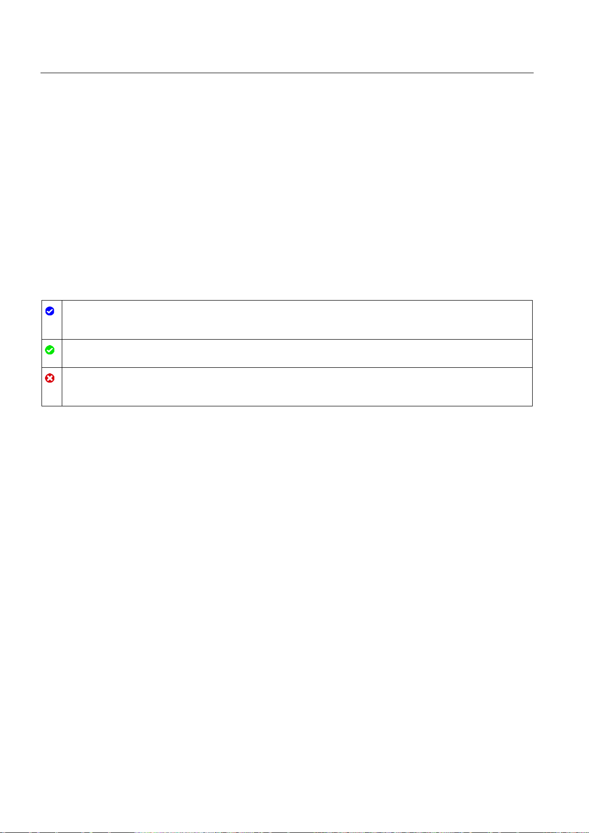
Configuring
6.3
Working with the configuration editor
Configuration editor icons
The configuration contains default values and is complete
additional changes.
The configuration contains values set by the user and is complete.
All input fields of the configuration contain valid values and at least one preset value has changed.
The configuration is incomplete or incorrect
displayed on a red background. Click the field shows you the roll-out error message that indicates the cause of error.
6.3 Working with the configuration editor
You configure the properties of a technology object in the configuration window. To open the
configuration window of the technology object in the project view, follow these steps:
1. Open the device "Technology objects" group in the project navigator.
2. Select the technology object and double-click on "Configuration".
The configuration is divided into categories which depend on the object type, for example:
Basic parameters, hardware interface, extended parameters.
Icons in the area navigation of the configuration show additional details about the status of
the configuration:
The configuration contains only default values. With these default values you can use the technology object without
.
At least one input field or drop-down list contains an invalid value. The corresponding field or the drop-down list is
S7-1500 Motion Control V13 Update 3
100 Function Manual, 07/2014, A5E03879256-AC
 Loading...