

Page 1
Page 2

___________________
___________________
___________________
___________________
___________________
___________________
___________________
___________________
___________________
___________________
___________________
SIMATIC
S7-1200, S7-1500 PID control
Function Manual
03/2017
A5E35300227
Preface
Documentation guide
1
Principles for control
2
Configuring a software
controller
3
Using PID_Compact
4
Using PID_3Step
5
Using PID_Temp
6
Using PID basic functions
7
Auxiliary functions
8
Instructions
9
Service & Support
A
-AC
Page 3
Siemens AG
Division Digital Factory
Postfach 48 48
90026 NÜRNBERG
GERMANY
A5E35300227-AC
Ⓟ
Copyright © Siemens AG 2017.
All rights reserved
Legal information
Warning notice system
DANGER
indicates that death or severe personal injury will result if proper precautions are not taken.
WARNING
indicates that death or severe personal injury may result if proper precautions are not taken.
CAUTION
indicates that minor personal injury can result if proper precautions are not taken.
NOTICE
indicates that property damage can result if proper precautions are not taken.
Qualified Personnel
personnel qualified
Proper use of Siemens products
WARNING
Siemens products may only be used for the applications described in the catalog and in the relevant technical
maintenance are required to ensure that the products operate safely and without any problems. The permissible
ambient conditions must be complied with. The information in the relevant documentation must be observed.
Trademarks
Disclaimer of Liability
This manual contains notices you have to observe in order to ensure your personal safety, as well as to prevent
damage to property. The notices referring to your personal safety are highlighted in the manual by a safety alert
symbol, notices referring only to property damage have no safety alert symbol. These notices shown below are
graded according to the degree of danger.
If more than one degree of danger is present, the warning notice representing the highest degree of danger will
be used. A notice warning of injury to persons with a safety alert symbol may also include a warning relating to
property damage.
The product/system described in this documentation may be operated only by
task in accordance with the relevant documentation, in particular its warning notices and safety instructions.
Qualified personnel are those who, based on their training and experience, are capable of identifying risks and
avoiding potential hazards when working with these products/systems.
Note the following:
documentation. If products and components from other manufacturers are used, these must be recommended
or approved by Siemens. Proper transport, storage, installation, assembly, commissioning, operation and
All names identified by ® are registered trademarks of Siemens AG. The remaining trademarks in this publication
may be trademarks whose use by third parties for their own purposes could violate the rights of the owner.
We have reviewed the contents of this publication to ensure consistency with the hardware and software
described. Since variance cannot be precluded entirely, we cannot guarantee full consistency. However, the
information in this publication is reviewed regularly and any necessary corrections are included in subsequent
editions.
for the specific
03/2017 Subject to change
Page 4

Preface
Purpose of the documentation
Basic knowledge required
Validity of the documentation
Conventions
Note
The notes contain important information on the product described in the d
the handling of the product or on part of the documentation to which particular attention
should be paid.
Additional assistance
This documentation will support you in configuring and programming control tasks with the
S7-1200 and S7-1500 automation systems.
The following knowledge is required in order to understand the documentation:
● General knowledge of automation technology
● Knowledge of the industrial automation system SIMATIC
● Experience of working with STEP 7 (TIA Portal)
This documentation applies to the use of SW controllers on the CPUs of automation systems
S7-1200 and S7-1500 together with STEP 7 (TIA Portal). Additional SW controllers that are
not covered in this documentation are available for the use of S7-300 and S7-400 with
STEP 7 (TIA Portal). Section Overview of software controller (Page 38) gives a complete
overview of all SW controllers in STEP 7 (TIA Portal) and their possible applications.
Please observe notes marked as follows:
● Information on the offers of our Technical Support are available in the appendix Service &
Support (Page 523).
● The range of technical documentation for the individual SIMATIC products and
automation systems is available on the Internet
(http://www.siemens.com/simatic-tech-doku-portal).
ocumentation, on
● The online catalog and the ordering system are available on the Internet
(http://mall.automation.siemens.com).
PID control
4 Function Manual, 03/2017, A5E35300227-AC
Page 5

Table of contents
Preface ................................................................................................................................................... 4
1 Documentation guide ............................................................................................................................ 12
2 Principles for control.............................................................................................................................. 16
3 Configuring a software controller ........................................................................................................... 38
2.1 Controlled system and actuators ............................................................................................ 16
2.2 Controlled systems ................................................................................................................. 18
2.3 Characteristic values of the control section ............................................................................ 20
2.4 Pulse controller ....................................................................................................................... 23
2.5 Response to setpoint changes and disturbances ................................................................... 27
2.6 Control Response at Different Feedback Structures .............................................................. 28
2.7 Selection of the controller structure for specified controlled systems ..................................... 36
2.8 PID parameter settings ........................................................................................................... 37
3.1 Overview of software controller .............................................................................................. 38
3.2 Steps for the configuration of a software controller ................................................................ 40
3.3 Add technology objects ........................................................................................................... 40
3.4 Configure technology objects ................................................................................................. 42
3.5 Call instruction in the user program ........................................................................................ 43
3.6 Downloading technology objects to device ............................................................................. 44
3.7 Commissioning software controller ......................................................................................... 45
3.8 Save optimized PID parameter in the project ......................................................................... 45
3.9 Comparing values ................................................................................................................... 46
3.9.1 Comparison display and boundary conditions ........................................................................ 46
3.9.2 Comparing values ................................................................................................................... 47
3.10 Parameter view ....................................................................................................................... 49
3.10.1 Introduction to the parameter view ......................................................................................... 49
3.10.2 Structure of the parameter view .............................................................................................. 51
3.10.2.1 Toolbar .................................................................................................................................... 51
3.10.2.2 Navigation ............................................................................................................................... 52
3.10.2.3 Parameter table ...................................................................................................................... 52
3.10.3 Opening the parameter view ................................................................................................... 54
3.10.4 Default setting of the parameter view ..................................................................................... 55
3.10.5 Working with the parameter view ............................................................................................ 57
3.10.5.1 Overview ................................................................................................................................. 57
3.10.5.2 Filtering the parameter table ................................................................................................... 58
3.10.5.3 Sorting the parameter table .................................................................................................... 59
3.10.5.4 Transferring parameter data to other editors .......................................................................... 59
PID control
Function Manual, 03/2017, A5E35300227-AC
5
Page 6

Table of contents
4 Using PID_Compact .............................................................................................................................. 72
5 Using PID_3Step ................................................................................................................................. 115
3.10.5.5 Indicating errors ..................................................................................................................... 60
3.10.5.6 Editing start values in the project ........................................................................................... 60
3.10.5.7 Status of configuration (offline) .............................................................................................. 62
3.10.5.8 Monitoring values online in the parameter view ..................................................................... 63
3.10.5.9 Change display format of value ............................................................................................. 64
3.10.5.10 Create snapshot of monitor values ........................................................................................ 65
3.10.5.11 Modifying values .................................................................................................................... 65
3.10.5.12 Comparing values .................................................................................................................. 67
3.10.5.13 Applying values from the online program as start values ...................................................... 68
3.10.5.14 Initializing setpoints in the online program ............................................................................. 70
3.11 Display instance DB of a technology object. .......................................................................... 71
4.1 Technology object PID_Compact........................................................................................... 72
4.2 PID_Compact V2.................................................................................................................... 73
4.2.1 Configuring PID_Compact V2 ................................................................................................ 73
4.2.1.1 Basic settings V2.................................................................................................................... 73
4.2.1.2 Process value settings V2 ...................................................................................................... 77
4.2.1.3 Advanced settings V2 ............................................................................................................ 78
4.2.2 Commissioning PID_Compact V2 .......................................................................................... 86
4.2.2.1 Pretuning V2 .......................................................................................................................... 86
4.2.2.2 Fine tuning V2 ........................................................................................................................ 88
4.2.2.3 "Manual" mode V1 ................................................................................................................. 90
4.2.3 Override control with PID_Compact V2 ................................................................................. 91
4.2.4 Simulating PID_Compact V2 with PLCSIM ............................................................................ 95
4.3 PID_Compact V1.................................................................................................................... 96
4.3.1 Configuring PID_Compact V1 ................................................................................................ 96
4.3.1.1 Basic settings V1.................................................................................................................... 96
4.3.1.2 Process value settings V1 .................................................................................................... 100
4.3.1.3 Advanced settings V1 .......................................................................................................... 101
4.3.2 Commissioning PID_Compact V1 ........................................................................................ 108
4.3.2.1 Commissioning V1 ............................................................................................................... 108
4.3.2.2 Pretuning V1 ........................................................................................................................ 109
4.3.2.3 Fine tuning V1 ...................................................................................................................... 111
4.3.2.4 "Manual" mode V1 ............................................................................................................... 113
4.3.3 Simulating PID_Compact V1 with PLCSIM .......................................................................... 114
5.1 Technology object PID_3Step .............................................................................................. 115
5.2 PID_3Step V2 ....................................................................................................................... 116
5.2.1 Configuring PID_3Step V2 ................................................................................................... 116
5.2.1.1 Basic settings V2.................................................................................................................. 116
5.2.1.2 Process value settings V2 .................................................................................................... 121
5.2.1.3 Final controlling element settings V2 ................................................................................... 122
5.2.1.4 Advanced settings V2 .......................................................................................................... 125
5.2.2 Commissioning PID_3Step V2 ............................................................................................. 129
5.2.2.1 Pretuning V2 ........................................................................................................................ 129
5.2.2.2 Fine tuning V2 ...................................................................................................................... 131
5.2.2.3 Commissioning with manual PID parameters V2 ................................................................ 133
5.2.2.4 Measuring the motor transition time V2 ............................................................................... 134
PID control
6 Function Manual, 03/2017, A5E35300227-AC
Page 7

Table of contents
6 Using PID_Temp ................................................................................................................................. 157
5.2.3 Simulating PID_3Step V2 with PLCSIM ................................................................................ 137
5.3 PID_3Step V1 ....................................................................................................................... 138
5.3.1 Configuring PID_3Step V1 .................................................................................................... 138
5.3.1.1 Basic settings V1 .................................................................................................................. 138
5.3.1.2 Process value settings V1 .................................................................................................... 143
5.3.1.3 V1 final controlling element setting ....................................................................................... 144
5.3.1.4 Advanced settings V1 ........................................................................................................... 147
5.3.2 Commissioning PID_3Step V1 .............................................................................................. 150
5.3.2.1 Commissioning V1 ................................................................................................................ 150
5.3.2.2 Pretuning V1 ......................................................................................................................... 151
5.3.2.3 Fine tuning V1 ....................................................................................................................... 152
5.3.2.4 Commissioning with manual PID parameters V1 ................................................................. 153
5.3.2.5 Measuring the motor transition time V1 ................................................................................ 154
5.3.3 Simulating PID_3Step V1 with PLCSIM ................................................................................ 156
6.1 Technology object PID_Temp ............................................................................................... 157
6.2 Configuring PID_Temp.......................................................................................................... 158
6.2.1 Basic settings ........................................................................................................................ 158
6.2.1.1 Introduction ........................................................................................................................... 158
6.2.1.2 Controller type ....................................................................................................................... 159
6.2.1.3 Setpoint ................................................................................................................................. 159
6.2.1.4 Process value ....................................................................................................................... 160
6.2.1.5 Heating and cooling output value ......................................................................................... 160
6.2.1.6 Cascade ................................................................................................................................ 162
6.2.2 Process value settings .......................................................................................................... 163
6.2.2.1 Process value limits .............................................................................................................. 163
6.2.2.2 Process value scaling ........................................................................................................... 163
6.2.3 Output settings ...................................................................................................................... 164
6.2.3.1 Basic settings of output ......................................................................................................... 164
6.2.3.2 Output value limits and scaling ............................................................................................. 167
6.2.4 Advanced settings ................................................................................................................. 170
6.2.4.1 Process value monitoring ..................................................................................................... 170
6.2.4.2 PWM limits ............................................................................................................................ 171
6.2.4.3 PID parameters ..................................................................................................................... 174
6.3 Commissioning PID_Temp ................................................................................................... 181
6.3.1 Commissioning ..................................................................................................................... 181
6.3.2 Pretuning ............................................................................................................................... 182
6.3.3 Fine tuning ............................................................................................................................ 185
6.3.4 "Manual" mode ...................................................................................................................... 189
6.3.5 Substitute setpoint ................................................................................................................ 190
6.3.6 Cascade commissioning ....................................................................................................... 190
6.4 Cascade control with PID_Temp .......................................................................................... 191
6.4.1 Introduction ........................................................................................................................... 191
6.4.2 Program creation .................................................................................................................. 193
6.4.3 Configuration ......................................................................................................................... 195
6.4.4 Commissioning ..................................................................................................................... 197
6.4.5 Substitute setpoint ................................................................................................................ 198
6.4.6 Operating modes and fault response .................................................................................... 198
PID control
Function Manual, 03/2017, A5E35300227-AC
7
Page 8

Table of contents
7 Using PID basic functions .................................................................................................................... 207
6.5 Multi-zone controlling with PID_Temp ................................................................................. 199
6.6 Override control with PID_Temp .......................................................................................... 202
6.7 Simulating PID_Temp with PLCSIM .................................................................................... 206
7.1 CONT_C ............................................................................................................................... 207
7.1.1 Technology object CONT_C ................................................................................................ 207
7.1.2 Configure controller difference CONT_C ............................................................................. 208
7.1.3 Configure the controller algorithm CONT_C ........................................................................ 209
7.1.4 Configure the output value CONT_C ................................................................................... 210
7.1.5 Programming a pulse controller ........................................................................................... 211
7.1.6 Commissioning CONT_C ..................................................................................................... 212
7.2 CONT_S ............................................................................................................................... 213
7.2.1 Technology object CONT_S ................................................................................................ 213
7.2.2 Configure controller difference CONT_S ............................................................................. 214
7.2.3 Configuring control algorithm CONT_S ............................................................................... 214
7.2.4 Configure manipulated value CONT_S ................................................................................ 215
7.2.5 Commissioning CONT_S ..................................................................................................... 215
7.3 TCONT_CP .......................................................................................................................... 216
7.3.1 Technology object TCONT_CP ............................................................................................ 216
7.3.2 Configure TCONT_CP ......................................................................................................... 217
7.3.2.1 Controller difference ............................................................................................................. 217
7.3.2.2 Controlling algorithm ............................................................................................................ 218
7.3.2.3 Manipulated value continual controller ................................................................................ 219
7.3.2.4 Manipulated value pulse controller ...................................................................................... 220
7.3.3 Commissioning TCONT_CP ................................................................................................ 222
7.3.3.1 Optimization of TCONT_CP ................................................................................................. 222
7.3.3.2 Requirements for an optimization ........................................................................................ 224
7.3.3.3 Possibilities for optimization ................................................................................................. 226
7.3.3.4 Tuning result ........................................................................................................................ 229
7.3.3.5 Parallel tuning of controller channels ................................................................................... 230
7.3.3.6 Fault descriptions and corrective measures ........................................................................ 231
7.3.3.7 Performing pretuning ........................................................................................................... 234
7.3.3.8 Performing fine tuning .......................................................................................................... 234
7.3.3.9 Cancelling pretuning or fine tuning ...................................................................................... 235
7.3.3.10 Manual fine-tuning in control mode ...................................................................................... 235
7.3.3.11 Performing fine tuning manually .......................................................................................... 236
7.4 TCONT_S ............................................................................................................................. 237
7.4.1 Technology object TCONT_S .............................................................................................. 237
7.4.2 Configure controller difference TCONT_S ........................................................................... 237
7.4.3 Configure controller algorithm TCONT_S ............................................................................ 238
7.4.4 Configure manipulated value TCONT_S ............................................................................. 239
7.4.5 Commissioning TCONT_S ................................................................................................... 239
PID control
8 Function Manual, 03/2017, A5E35300227-AC
Page 9

Table of contents
8 Auxiliary functions ............................................................................................................................... 240
9 Instructions ......................................................................................................................................... 241
8.1 Polyline ................................................................................................................................. 240
9.1 PID_Compact ........................................................................................................................ 241
9.1.1 New features of PID_Compact ............................................................................................. 241
9.1.2 Compatibility with CPU and FW ............................................................................................ 244
9.1.3 CPU processing time and memory requirement PID_Compact V2.x ................................... 245
9.1.4 PID_Compact V2 .................................................................................................................. 246
9.1.4.1 Description of PID_Compact V2 ........................................................................................... 246
9.1.4.2 Mode of operation of PID_Compact V2 ................................................................................ 249
9.1.4.3 Input parameters of PID_Compact V2 .................................................................................. 251
9.1.4.4 Output parameters of PID_Compact V2 ............................................................................... 253
9.1.4.5 In/out parameters of PID_Compact V2 ................................................................................. 254
9.1.4.6 Static tags of PID_Compact V2 ............................................................................................ 255
9.1.4.7 Changing the PID_Compact V2 interface ............................................................................. 263
9.1.4.8 Parameters State and Mode V2 ........................................................................................... 265
9.1.4.9 Parameter ErrorBits V2 ......................................................................................................... 269
9.1.4.10 Tag ActivateRecoverMode V2 .............................................................................................. 271
9.1.4.11 Tag Warning V2 .................................................................................................................... 273
9.1.4.12 IntegralResetMode V2 tag .................................................................................................... 274
9.1.4.13 Sample program for PID_Compact ....................................................................................... 276
9.1.5 PID_Compact V1 .................................................................................................................. 283
9.1.5.1 Description of PID_Compact V1 ........................................................................................... 283
9.1.5.2 Input parameters of PID_Compact V1 .................................................................................. 286
9.1.5.3 Output parameters of PID_Compact V1 ............................................................................... 287
9.1.5.4 Static tags of PID_Compact V1 ............................................................................................ 288
9.1.5.5 Parameters State and sRet.i_Mode V1 ................................................................................ 293
9.1.5.6 Parameter Error V1 ............................................................................................................... 297
9.1.5.7 Parameter Reset V1 ............................................................................................................. 298
9.1.5.8 Tag sd_warning V1 ............................................................................................................... 300
9.1.5.9 Tag i_Event_SUT V1 ............................................................................................................. 300
9.1.5.10 Tag i_Event_TIR V1 .............................................................................................................. 301
9.2 PID_3Step ............................................................................................................................. 302
9.2.1 New features of PID_3Step .................................................................................................. 302
9.2.2 Compatibility with CPU and FW ............................................................................................ 304
9.2.3 CPU processing time and memory requirement PID_3Step V2.x ........................................ 305
9.2.4 PID_3Step V2 ....................................................................................................................... 306
9.2.4.1 Description of PID_3Step V2 ................................................................................................ 306
9.2.4.2 Mode of operation of PID_3Step V2 ..................................................................................... 312
9.2.4.3 Changing the PID_3Step V2 interface .................................................................................. 315
9.2.4.4 Input parameters of PID_3Step V2 ....................................................................................... 316
9.2.4.5 Output parameters of PID_3Step V2
....................................................................................
9.2.4.6 In/out parameters of PID-3Step V2 ....................................................................................... 320
9.2.4.7 Static tags of PID_3Step V2 ................................................................................................. 321
9.2.4.8 Parameters State and Mode V2 ........................................................................................... 330
9.2.4.9 Parameter ErrorBits V2 ......................................................................................................... 335
9.2.4.10 Tag ActivateRecoverMode V2 .............................................................................................. 338
9.2.4.11 Tag Warning V2 .................................................................................................................... 340
PID control
Function Manual, 03/2017, A5E35300227-AC
318
9
Page 10

Table of contents
9.2.5 PID_3Step V1 ....................................................................................................................... 341
9.2.5.1 Description PID_3Step V1 ................................................................................................... 341
9.2.5.2 Operating principle PID_3Step V1 ....................................................................................... 347
9.2.5.3 PID_3Step V1 input parameters .......................................................................................... 350
9.2.5.4 PID_3Step V1 output parameters ........................................................................................ 352
9.2.5.5 PID_3Step V1 static tags ..................................................................................................... 354
9.2.5.6 Parameter State and Retain.Mode V1 ................................................................................. 361
9.2.5.7 Parameter ErrorBits V1 ........................................................................................................ 369
9.2.5.8 Parameter Reset V1 ............................................................................................................ 371
9.2.5.9 Tag ActivateRecoverMode V1 ............................................................................................. 372
9.2.5.10 Tag Warning V1 ................................................................................................................... 374
9.2.5.11 Tag SUT.State V1 ................................................................................................................ 375
9.2.5.12 Tag TIR.State V1 ................................................................................................................. 375
9.3 PID_Temp ............................................................................................................................ 376
9.3.1 New features of PID_Temp .................................................................................................. 376
9.3.2 Compatibility with CPU and FW ........................................................................................... 376
9.3.3 CPU processing time and memory requirement PID_Temp V1 .......................................... 377
9.3.4 PID_Temp ............................................................................................................................ 378
9.3.4.1 Description of PID_Temp ..................................................................................................... 378
9.3.4.2 Mode of operation of PID_Temp .......................................................................................... 383
9.3.4.3 Input parameters of PID_Temp ............................................................................................ 389
9.3.4.4 Output parameters of PID_Temp ......................................................................................... 391
9.3.4.5 In/out parameters of PID_Temp V2 ..................................................................................... 393
9.3.4.6 PID_Temp static tags ........................................................................................................... 395
9.3.4.7 PID_Temp state and mode parameters ............................................................................... 430
9.3.4.8 PID_Temp ErrorBits parameter ............................................................................................ 439
9.3.4.9 PID_Temp ActivateRecoverMode tag .................................................................................. 442
9.3.4.10 PID_Temp Warning tag ........................................................................................................ 444
9.3.4.11 PwmPeriode tag ................................................................................................................... 445
9.3.4.12 IntegralResetMode tag ......................................................................................................... 447
9.4 PID basic functions .............................................................................................................. 449
9.4.1 CONT_C ............................................................................................................................... 449
9.4.1.1 Description CONT_C ........................................................................................................... 449
9.4.1.2 How CONT_C works ............................................................................................................ 450
9.4.1.3 CONT_C block diagram ....................................................................................................... 452
9.4.1.4 Input parameter CONT_C .................................................................................................... 453
9.4.1.5 Out
put parameters CONT_C ............................................................................................... 454
9.4.2 CONT_S ............................................................................................................................... 455
9.4.2.1 Description CONT_S ............................................................................................................ 455
9.4.2.2 Mode of operation CONT_S ................................................................................................. 456
9.4.2.3 Block diagram CONT_S ....................................................................................................... 457
9.4.2.4 Input parameters CONT_S .................................................................................................. 458
9.4.2.5 Output parameters CONT_S ................................................................................................ 459
9.4.3 PULSEGEN .......................................................................................................................... 460
9.4.3.1 Description PULSEGEN ...................................................................................................... 460
9.4.3.2 Mode of operation PULSEGEN ........................................................................................... 461
9.4.3.3 Mode of operation PULSEGEN ........................................................................................... 464
9.4.3.4 Three-step control ................................................................................................................ 465
9.4.3.5 Two-step control................................................................................................................... 468
9.4.3.6 Input parameters PULSEGEN ............................................................................................. 469
9.4.3.7 Output parameter PULSEGEN ............................................................................................ 470
PID control
10 Function Manual, 03/2017, A5E35300227-AC
Page 11

Table of contents
A Service & Support ............................................................................................................................... 523
Index................................................................................................................................................... 526
9.4.4 TCONT_CP ........................................................................................................................... 471
9.4.4.1 Description TCONT_CP ........................................................................................................ 471
9.4.4.2 Mode of operation TCONT_CP ............................................................................................. 472
9.4.4.3 Operating principle of the pulse generator ........................................................................... 481
9.4.4.4 Block diagram TCONT_CP ................................................................................................... 484
9.4.4.5 Input parameters TCONT_CP .............................................................................................. 486
9.4.4.6 Output parameters TCONT_CP ............................................................................................ 487
9.4.4.7 In/out parameters TCONT_CP ............................................................................................. 488
9.4.4.8 Static variables TCONT_CP ................................................................................................. 489
9.4.4.9 Parameter STATUS_H.......................................................................................................... 494
9.4.4.10 Parameters STATUS_D ........................................................................................................ 495
9.4.5 TCONT_S ............................................................................................................................. 496
9.4.5.1 Description TCONT_S .......................................................................................................... 496
9.4.5.2 Mode of operation TCONT_S ............................................................................................... 497
9.4.5.3 Block diagram TCONT_S...................................................................................................... 501
9.4.5.4 Input paramters TCONT_S ................................................................................................... 503
9.4.5.5 Output parameters TCONT_S .............................................................................................. 504
9.4.5.6 In/out parameters TCONT_S ................................................................................................ 504
9.4.5.7 Static variables TCONT_S .................................................................................................... 505
9.4.6 Integrated system functions .................................................................................................. 506
9.4.6.1 CONT_C_SF ......................................................................................................................... 506
9.4.6.2 CONT_S_SF ......................................................................................................................... 506
9.4.6.3 PULSEGEN_SF .................................................................................................................... 507
9.5 Polyline ................................................................................................................................. 508
9.5.1 Compatibility with CPU and FW ............................................................................................ 508
9.5.2 Description Polyline .............................................................................................................. 508
9.5.3 Operating principle Polyline .................................................................................................. 512
9.5.4 Input parameters of Polyline ................................................................................................. 516
9.5.5 Output parameters of Polyline .............................................................................................. 516
9.5.6 Static tags of Polyline............................................................................................................ 517
9.5.7 ErrorBits parameter ............................................................................................................... 518
PID control
Function Manual, 03/2017, A5E35300227-AC
11
Page 12
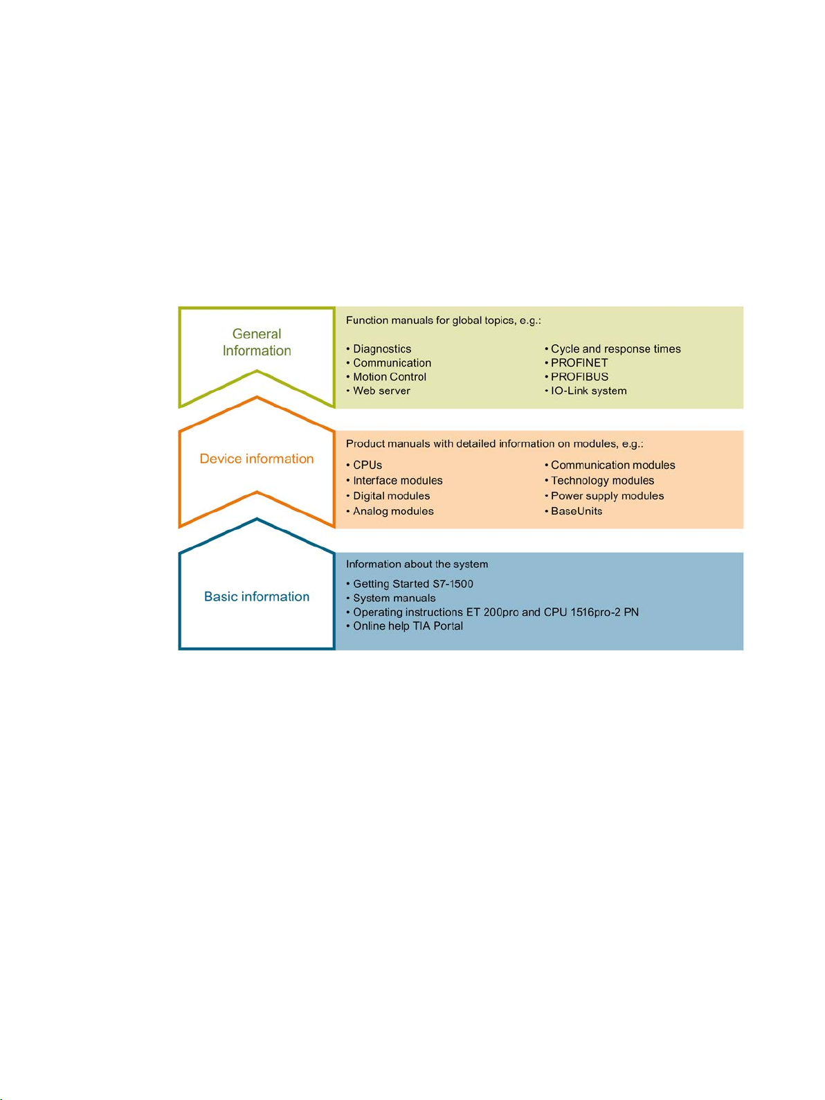
1
Basic information
Device information
The documentation for the SIMATIC S7-1500 automation system, for CPU 1516pro-2 PN
based on SIMATIC S7-1500, and for the distributed I/O systems SIMATIC ET 200MP,
ET 200SP and ET 200AL is divided into three areas.
This division allows you easier access to the specific information you require.
System manuals and Getting Started manuals describe in detail the configuration,
installation, wiring and commissioning of the SIMATIC S7-1500, ET 200MP, ET 200SP and
ET 200AL systems; use the corresponding operating instructions for CPU 1516pro-2 PN.
The STEP 7 online help supports you in configuration and programming.
Product manuals contain a compact description of the module-specific information, such as
properties, terminal diagrams, characteristics and technical specifications.
PID control
12 Function Manual, 03/2017, A5E35300227-AC
Page 13

Documentation guide
General information
Manual Collections
"mySupport"
"mySupport" - Documentation
The function manuals contain detailed descriptions on general topics such as diagnostics,
communication, Motion Control, Web server, OPC UA.
You can download the documentation free of charge from the Internet
(http://w3.siemens.com/mcms/industrial-automation-systems-simatic/en/manual-
overview/Pages/Default.aspx).
Changes and additions to the manuals are documented in product information sheets.
You will find the product information on the Internet:
● S7-1500/ET 200MP (https://support.industry.siemens.com/cs/us/en/view/68052815)
● ET 200SP (https://support.industry.siemens.com/cs/us/en/view/73021864)
● ET 200AL (https://support.industry.siemens.com/cs/us/en/view/99494757)
The Manual Collections contain the complete documentation of the systems put together in
one file.
You will find the Manual Collections on the Internet:
● S7-1500/ET 200MP (https://support.industry.siemens.com/cs/ww/en/view/86140384)
● ET 200SP (https://support.industry.siemens.com/cs/ww/en/view/84133942)
● ET 200AL (https://support.industry.siemens.com/cs/ww/en/view/95242965)
With "mySupport", your personal workspace, you make the best out of your Industry Online
Support.
In "mySupport", you can save filters, favorites and tags, request CAx data and compile your
personal library in the Documentation area. In addition, your data is already filled out in
support requests and you can get an overview of your current requests at any time.
You must register once to use the full functionality of "mySupport".
You can find "mySupport" on the Internet (https://support.industry.siemens.com/My/ww/en).
In the Documentation area in "mySupport" you can combine entire manuals or only parts of
these to your own manual.
You can export the manual as PDF file or in a format that can be edited later.
You can find "mySupport" - Documentation on the Internet
(http://support.industry.siemens.com/My/ww/en/documentation).
PID control
Function Manual, 03/2017, A5E35300227-AC
13
Page 14

Documentation guide
"mySupport" - CAx data
Application examples
TIA Selection Tool
SIMATIC Automation Tool
In the CAx data area in "mySupport", you can access the current product data for your CAx
or CAe system.
You configure your own download package with a few clicks.
In doing so you can select:
● Product images, 2D dimension drawings, 3D models, internal circuit diagrams, EPLAN
macro files
● Manuals, characteristics, operating manuals, certificates
● Product master data
You can find "mySupport" - CAx data on the Internet
(http://support.industry.siemens.com/my/ww/en/CAxOnline).
The application examples support you with various tools and examples for solving your
automation tasks. Solutions are shown in interplay with multiple components in the system separated from the focus on individual products.
You will find the application examples on the Internet
(https://support.industry.siemens.com/sc/ww/en/sc/2054).
With the TIA Selection Tool, you can select, configure and order devices for Totally
Integrated Automation (TIA).
This tool is the successor of the SIMATIC Selection Tool and combines the known
configurators for automation technology into one tool.
With the TIA Selection Tool, you can generate a complete order list from your product
selection or product configuration.
You can find the TIA Selection Tool on the Internet
(http://w3.siemens.com/mcms/topics/en/simatic/tia-selection-tool).
You can use the SIMATIC Automation Tool to run commissioning and maintenance activities
simultaneously on different SIMATIC S7 stations as a bulk operation, independently of the
TIA Portal.
The SIMATIC automation tool provides a variety of functions:
● Scanning of a PROFINET/Ethernet plant network and identification of all connected CPUs
● Address assignment (IP, subnet, gateway) and station name (PROFINET device) to a
CPU
● Transfer of the date and programming device/PC time converted to UTC time to the
module
● Program download to CPU
PID control
14 Function Manual, 03/2017, A5E35300227-AC
Page 15

Documentation guide
PRONETA
● Operating mode switchover RUN/STOP
● CPU localization by means of LED flashing
● Reading out CPU error information
● Reading of CPU diagnostic buffer
● Reset to factory settings
● Updating the firmware of the CPU and connected modules
You can find the SIMATIC Automation Tool on the Internet
(https://support.industry.siemens.com/cs/ww/en/view/98161300).
With SIEMENS PRONETA (PROFINET network analysis), you analyze the plant network
during commissioning. PRONETA features two core functions:
● The topology overview independently scans PROFINET and all connected components.
● The IO check is a fast test of the wiring and the module configuration of a plant.
You can find SIEMENS PRONETA on the Internet
(https://support.industry.siemens.com/cs/ww/en/view/67460624).
PID control
Function Manual, 03/2017, A5E35300227-AC
15
Page 16
2
2.1
Controlled system and actuators
Controlled system
Actuators
Application
Actuator
Liquid and gaseous mass flow
Valve, shutter, gate valve
Solid mass flow, e.g., bulk material
Articulated baffle, conveyor, vibrator channel
Switching contact, contactor, relay, thyristor
Variable resistor, variable transformer, transistor
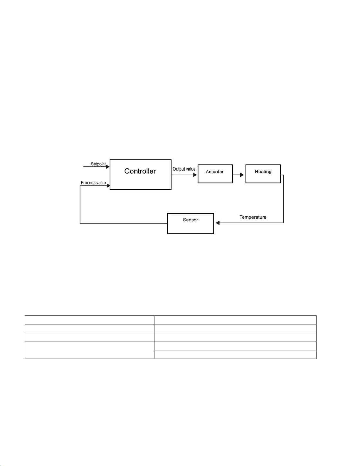
Room temperature control by means of a heating system is a simple example of a controlled
system. A sensor measures the room temperature and transfers the value to a controller.
The controller compares the current room temperature with a setpoint and calculates an
output value (manipulated variable) for heating control.
A properly set PID controller reaches this setpoint as quickly as possible and then holds it a
constant value. After a change in the output value, the process value often changes only with
a time delay. The controller has to compensate for this response.
The actuator is an element of the controlled system and is influenced by the controller. Its
function modifies mass and energy flows.
The table below provides an overview of actuator applications.
Flow of electrical power
PID control
16 Function Manual, 03/2017, A5E35300227-AC
Page 17

Principles for control
2.1 Controlled system and actuators
Actuators are distinguished as follows:
● Proportional actuators with constant actuating signal
These elements set degrees of opening, angular positions or positions in proportion to
the output value. The output value has an analog effect on the process within the control
range.
Actuators in this group include spring-loaded pneumatic drives, as well as motorized
drives with position feedback for which a position control system is formed.
An continuous controller, such as PID_Compact, generates the output value.
● Proportional actuators with pulse-width modulated signal
These actuators are used to generate the output of pulses with a length proportional to
the output value within the sampling time intervals. The actuator - e.g. a heating resistor
or cooling apparatus - is switched on in isochronous mode for durations that differ
depending on the output value.
The actuating signal can assume unipolar "On" or "Off" states, or represent bipolar states
such as "open/close", "forward/backward", "accelerate/brake".
The output value is generated by a two-step controller such as PID_Compact with pulsewidth modulation.
● Actuators with integral action and three-step actuating signal
Actuators are frequently operated by motors with an on period that is proportional to the
actuator travel of the choke element. This includes elements such as valves, shutters,
and gate valves. In spite of their different design, all of these actuators follow the effect of
an integral action at the input of the controlled system.
A step controller, such as PID_3Step. generates the output value.
PID control
Function Manual, 03/2017, A5E35300227-AC
17
Page 18

Principles for control
2.2
Controlled systems
Controlled system types
Self-regulating controlled systems
Proportional-action controlled systems
PT1 controlled systems
2.2 Controlled systems
The properties of a controlled system can hardly be influenced as these are determined by
the technical requirements of the process and machinery. Acceptable control results can
only be achieved by selecting a suitable controller type for the specific controlled system and
adapting the controller to the time response of the controlled system. Therefore, it is is
indispensable for the configuration of the proportional, integral and derivative actions of the
controller to have precise knowledge of the type and parameters of the controlled system.
Controlled systems are classified based on their time response to step changes of the output
value.
We distinguish between the following controlled systems:
● Self-regulating controlled systems
– Proportional-action controlled systems
– PT1 controlled systems
– PT2 controlled systems
● Non-self-regulating controlled systems
● Controlled systems with and without dead time
In proportional-action controlled systems, the process value follows the output value almost
immediately. The ratio between the process value and output value is defined by the
proportional Gain of the controlled system.
Examples:
● Gate valve in a piping system
● Voltage dividers
● Step-down function in hydraulic systems
In a PT1 controlled system, the process value initially changes in proportion to the change of
the output value. The rate of change of the process value is reduced as a function of the time
until the end value is reached, i.e., it is delayed.
Examples:
● Spring damping system
● Charge of RC elements
● Water container that is heated with steam.
The time constants are often identical for heating and cooling processes, or for charging and
discharge characteristics. With different time constants, controlling is clearly more complex.
PID control
18 Function Manual, 03/2017, A5E35300227-AC
Page 19

Principles for control
PT2 controlled systems
Non-self-regulating controlled systems
Controlled systems with dead time
2.2 Controlled systems
In a PT2 controlled system, the process value does not immediately follow a step change of
the output value, i.e., it increases in proportion to the positive rate of rise and then
approaches the setpoint at a decreasing rate of rise. The controlled system shows a
proportional response characteristic with second order delay element.
Examples:
● Pressure control
● Flow rate control
● Temperature control
Non-self-regulating controlled systems have an integral response. The process value
approaches an infinite maximum value.
Example:
● Liquid flow into a container
A dead time always represents the runtime or transport time that has to expire before a
change to the system input can be measured at the system output.
In controlled systems with dead time, the process value change is delayed by the amount of
the dead time.
Example:
Conveyor
PID control
Function Manual, 03/2017, A5E35300227-AC
19
Page 20
Principles for control
2.3
Characteristic values of the control section
Determining the time response from the step response
2.3 Characteristic values of the control section
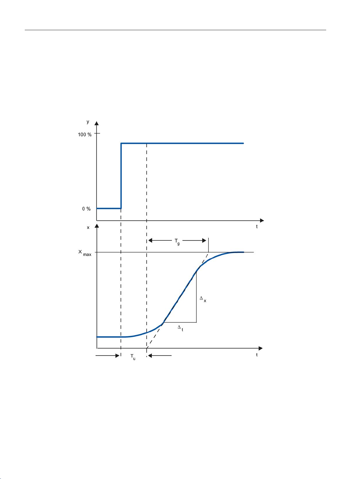
Time response of the controlled system can be determined based on the time characteristic
of process value x following a step change of output value y. Most controlled systems are
self-regulating controlled systems.
The time response can be determined by approximation using the variables Delay time Tu,
Recovery time T
and Maximum value X
g
. The variables are determined by applying
max
tangents to the maximum value and the inflection point of the step response. In many
situations, it is not possible to record the response characteristic up to the maximum value
because the process value cannot exceed specific values. In this case, the rate of rise v
used to identify the controlled system (v
PID control
= Δx/Δt).
max
max
is
20 Function Manual, 03/2017, A5E35300227-AC
Page 21
Principles for control
Process type
Tu / Tg
Suitability of the controlled system for controlling
I
< 0,1
can be controlled well
III
> 0,3
difficult to control
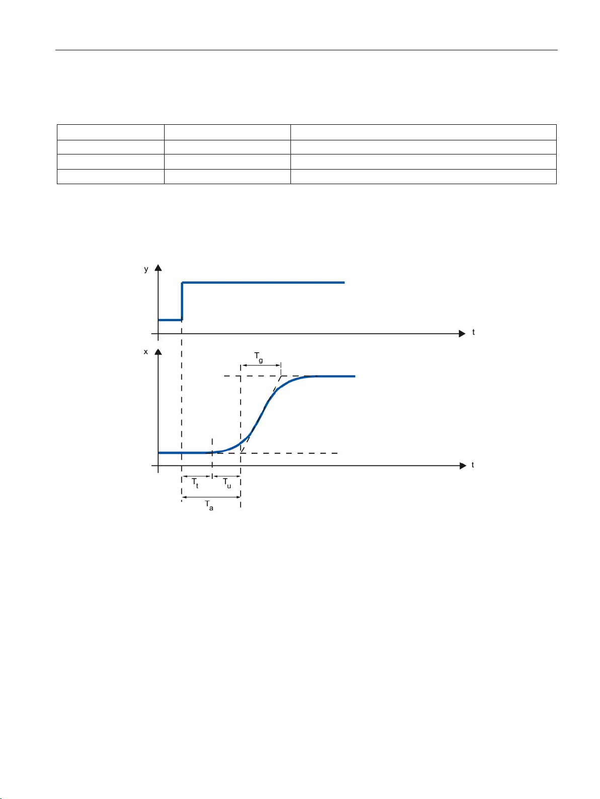
Influence of the dead time on the controllability of a controlled system
Tt
Dead time
Tu
Delay time
Tg
Recovery time
y
Output value
x
Process value
2.3 Characteristic values of the control section
The controllability of the controlled system can be estimated based on the ratio Tu/Tg, or Tu ×
v
max/Xmax
II 0.1 to 0.3 can still be controlled
. Rule:
A controlled system with dead time and recovery reacts as follows to a jump of the output
value.
The controllability of a self-regulating controlled system with dead time is determined by the
ratio of T
T
t/Tg
PID control
Function Manual, 03/2017, A5E35300227-AC
to Tg. Tt must be small compared to Tg. Rule:
t
≤ 1
21
Page 22

Principles for control
Response rate of controlled systems
Parameters of certain controlled systems
Physical
quantity
Controlled system
Delay time Tu
Recovery time Tg
Rate of rise v
max
Small electrically heated furnace
0.5 to 1 min
5 to 15 min
Up to 60 K/min.
Large gas-heated annealing furnace
0.2 to 5 min
3 to 60 min
1 to 30 K/min
Autoclaves (2.5 m3)
0.5 to 0.7 min
10 to 20 min
Not specified
High-pressure autoclaves
12 to 15 min
200 to 300 min
Not specified
Steam superheater
30 s to 2.5 min
1 to 4 min
2°C/s
Injection molding machines
0.5 to 3 min
3 to 30 min
5 to 20 K/min
Extruders
1 to 6 min
5 to 60 min
Packaging machines
0.5 to 4 min
3 to 40 min
2 to 35 K/min
Room heating
1 to 5 min
10 to 60 min
1° C/min
Pipeline with gas
0 to 5 s
0.2 to 10 s
Pipeline with liquid
None
None
Gas pipeline
None
0.1 s
Not relevant
Drum boiler with gas or oil firing
None
150 s
Not relevant
Drum boiler with impact grinding mills
1 to 2 min
2 to 5 min
Not relevant
Vessel level
Drum boiler
0.6 to 1 min
Not specified
0.1 to 0.3 cm/s
Small electric drive
None
0.2 to 10 s
Not relevant
Large electric drive
None
5 to 40 s
Not relevant
Steam turbine
None
Not specified
50 min–1
Small generators
None
1 to 5 s
Not relevant
Large generators
None
5 to 10 s
Not relevant
2.3 Characteristic values of the control section
Controlled systems can be judged on the basis of the following values:
T
< 0.5 min, Tg < 5 min = fast controlled system
u
T
> 0.5 min, Tg > 5 min = slow controlled system
u
Temperature
Large electrically heated annealing furnace
Distillation tower 1 to 7 min 40 to 60 min 0.1 to 0.5° C/s
1 to 5 min 10 to 20 min Up to 20 K/min.
Flow rate
Pressure
Speed
Voltage
Not relevant
PID control
22 Function Manual, 03/2017, A5E35300227-AC
Page 23
Principles for control
2.4
Pulse controller
Two-step controllers without feedback
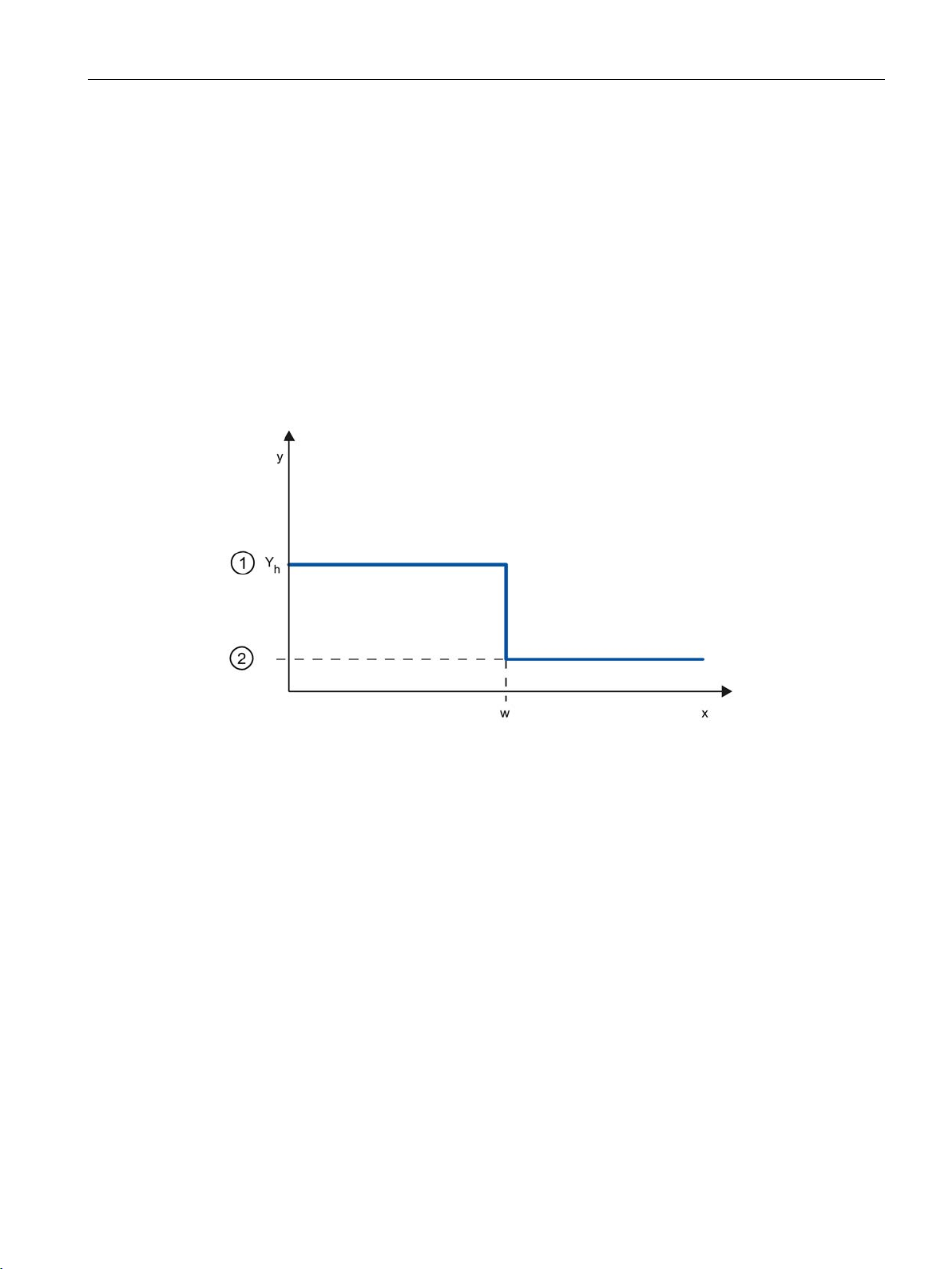
①
ON
②
OFF
Yh
Control range
w
Setpoint
2.4 Pulse controller
Two-step controllers have the state "ON" and "OFF" as the switching function. This
corresponds to 100% or 0% output. This behavior generates a sustained oscillation of
process value x around setpoint w.
The amplitude and duration of the oscillation increase in proportion to the ratio between the
delay time T
mainly for simple temperature control systems (such as electrically directly heated furnaces)
or as limit-value signaling units.
The following diagram shows the characteristic of a two-step controller
and recovery time Tg of the controlled system. These controllers are used
u
PID control
Function Manual, 03/2017, A5E35300227-AC
23
Page 24
Principles for control
①
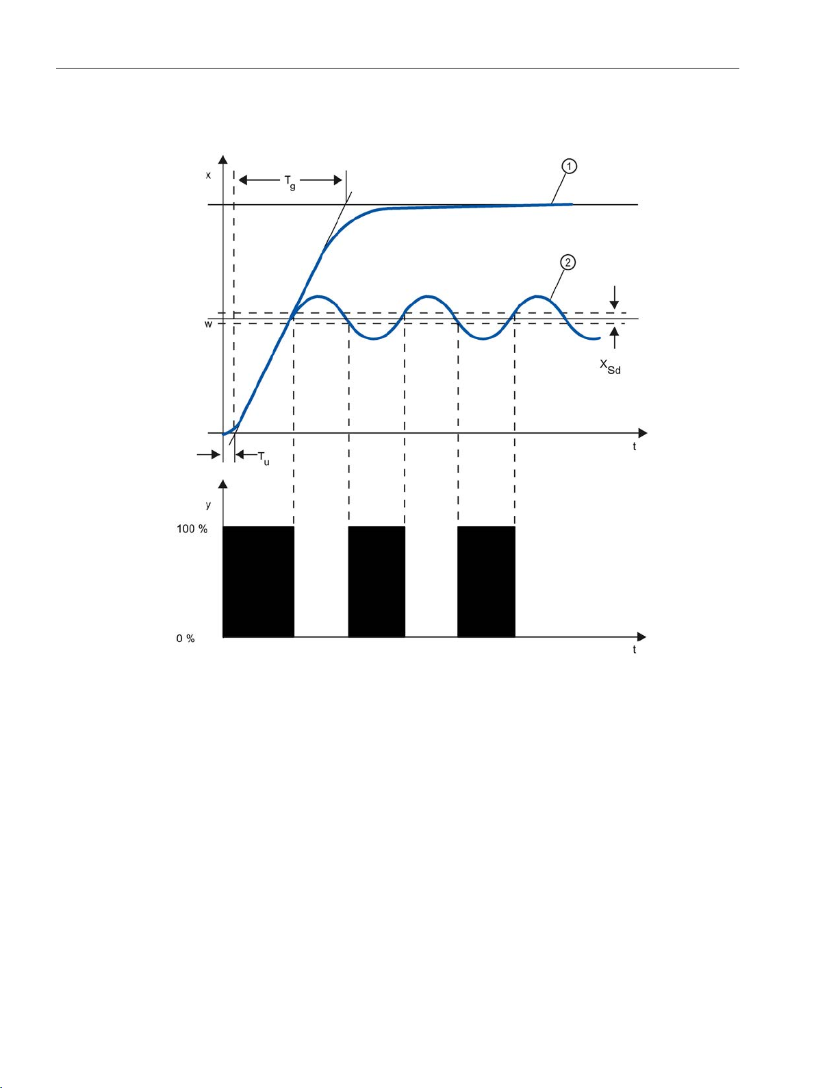
Response characteristic without controller
②
Response characteristic with two-step controller
Tu
Delay time
Tg
Recovery time
XSd
Switching difference
2.4 Pulse controller
The following diagram shows the control function of a two-step controller
PID control
24 Function Manual, 03/2017, A5E35300227-AC
Page 25

Principles for control
Two-step controllers with feedback
2.4 Pulse controller
The behavior of two-step controllers in the case of controlled systems with larger delay
times, such as furnaces where the functional space is separated from the heating, can be
improved by the use of electronic feedback.
The feedback is used to increase the switching frequency of the controller, which reduces
the amplitude of the process value. In addition, the control-action results can be improved
substantially in dynamic operation. The limit for the switching frequency is set by the output
level. It should not exceed 1 to 5 switches per minute at mechanical actuators, such as
relays and contactors. In the case of voltage and current outputs with downstream thyristor
or Triac controllers high switching frequencies can be selected that exceed the limit
frequency of the controlled system by far.
Since the switching pulses can no longer be determined at the output of the controlled
system, results comparable with those of continuous controllers are obtained.
The output value is generated by pulse-width modulation of the output value of a continuous
controller.
Two-step controllers with feedback are used for temperature control in furnaces, at
processing machines in the plastics, textile, paper, rubber and foodstuff industries as well as
for heating and cooling devices.
PID control
Function Manual, 03/2017, A5E35300227-AC
25
Page 26
Principles for control
Three-step controllers
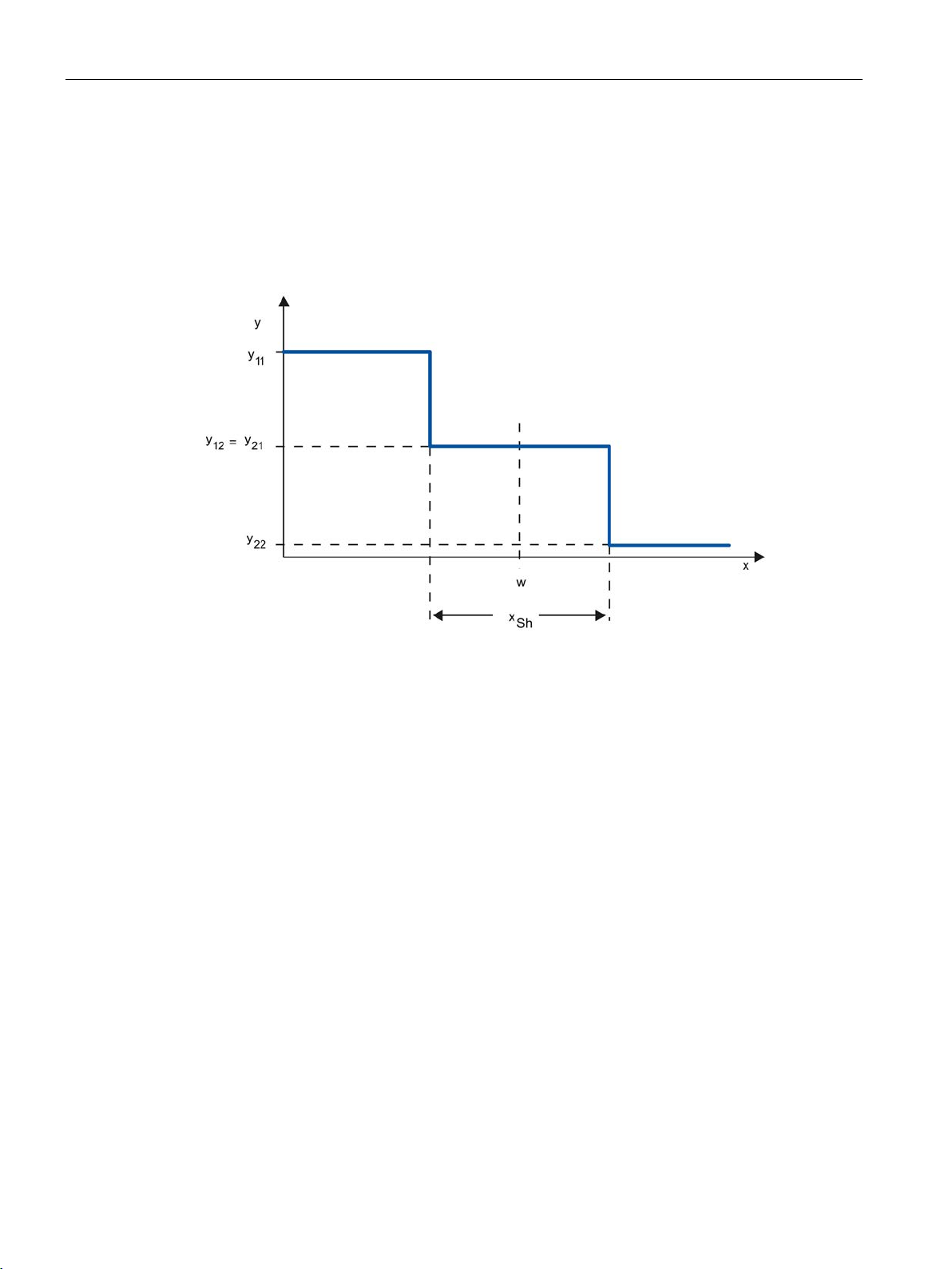
y22 = 100% cooling
x
Physical quantity of the process value, e.g., temperature in° C
w
Setpoint
xSh
Distance between Switching Point 1 and Switching Point 2
2.4 Pulse controller
Three-step controllers are used for heating / cooling. These controllers have two switching
points as their output. The control-action results are optimized through electronic feedback
structures. Fields of applications for such controllers are heating, low-temperature, climatic
chambers and tool heating units for plastic-processing machines.
The following diagram shows the characteristic of a three-step controller
y Output value, e.g.
y11 = 100% heating
y12 = 0% heating
y21 = 0% cooling
PID control
26 Function Manual, 03/2017, A5E35300227-AC
Page 27

Principles for control
2.5
Response to setpoint changes and disturbances
Response to setpoint changes
x
Process value
w
Setpoint
2.5 Response to setpoint changes and disturbances
The process value should follow a setpoint change as quickly as possible. The response to
setpoint changes is improved by minimizing fluctuation of the process value and the time
required to reach the new setpoint.
PID control
Function Manual, 03/2017, A5E35300227-AC
27
Page 28
Principles for control
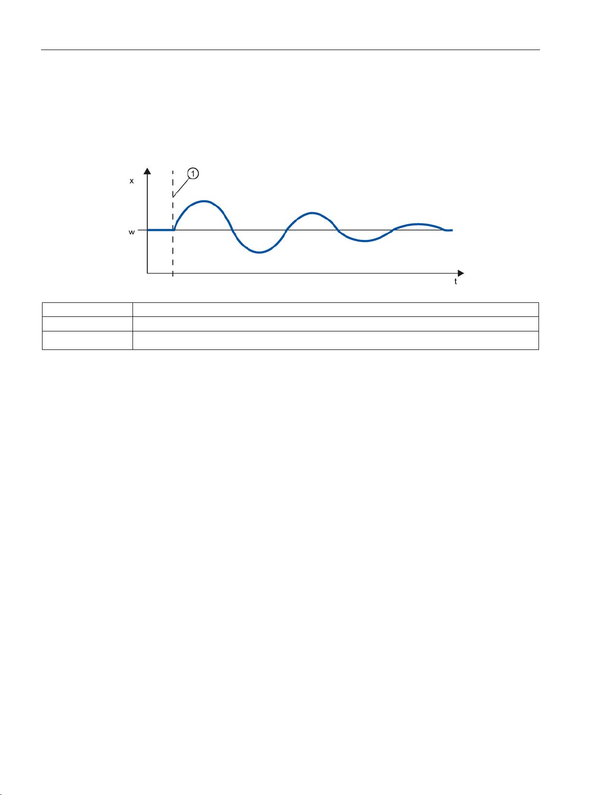
Response to disturbances
x
Process value
①
2.6
Control Response at Different Feedback Structures
Control behavior of controllers
2.6 Control Response at Different Feedback Structures
The setpoint is influenced by disturbance variables. The controller has to eliminate the
resulting control deviations in the shortest time possible. The response to disturbances is
improved by minimizing fluctuation of the process value and the time required to reach the
new setpoint.
w Setpoint
Influencing a disturbance variable
Disturbance variables are corrected by a controller with integral action. A persistent
disturbance variable does not reduce control quality because the control deviation is
relatively constant. Dynamic disturbance variables have a more significant impact on control
quality because of control deviation fluctuation. The control deviation is eliminated again only
by means of the slow acting integral action.
A measurable disturbance variable can be included in the controlled system. This inclusion
would significantly accelerated the response of the controller.
A precise adaptation of the controller to the time response of the controlled system is
decisive for the controller's precise settling to the setpoint and optimum response to
disturbance variables.
The feedback circuit can have a proportional action (P), proportional-derivative action (PD),
proportional-integral action (PI), or proportional-integral-derivative action (PID).
If step functions are to be triggered by control deviations, the step responses of the
controllers differ depending on their type.
PID control
28 Function Manual, 03/2017, A5E35300227-AC
Page 29
Principles for control
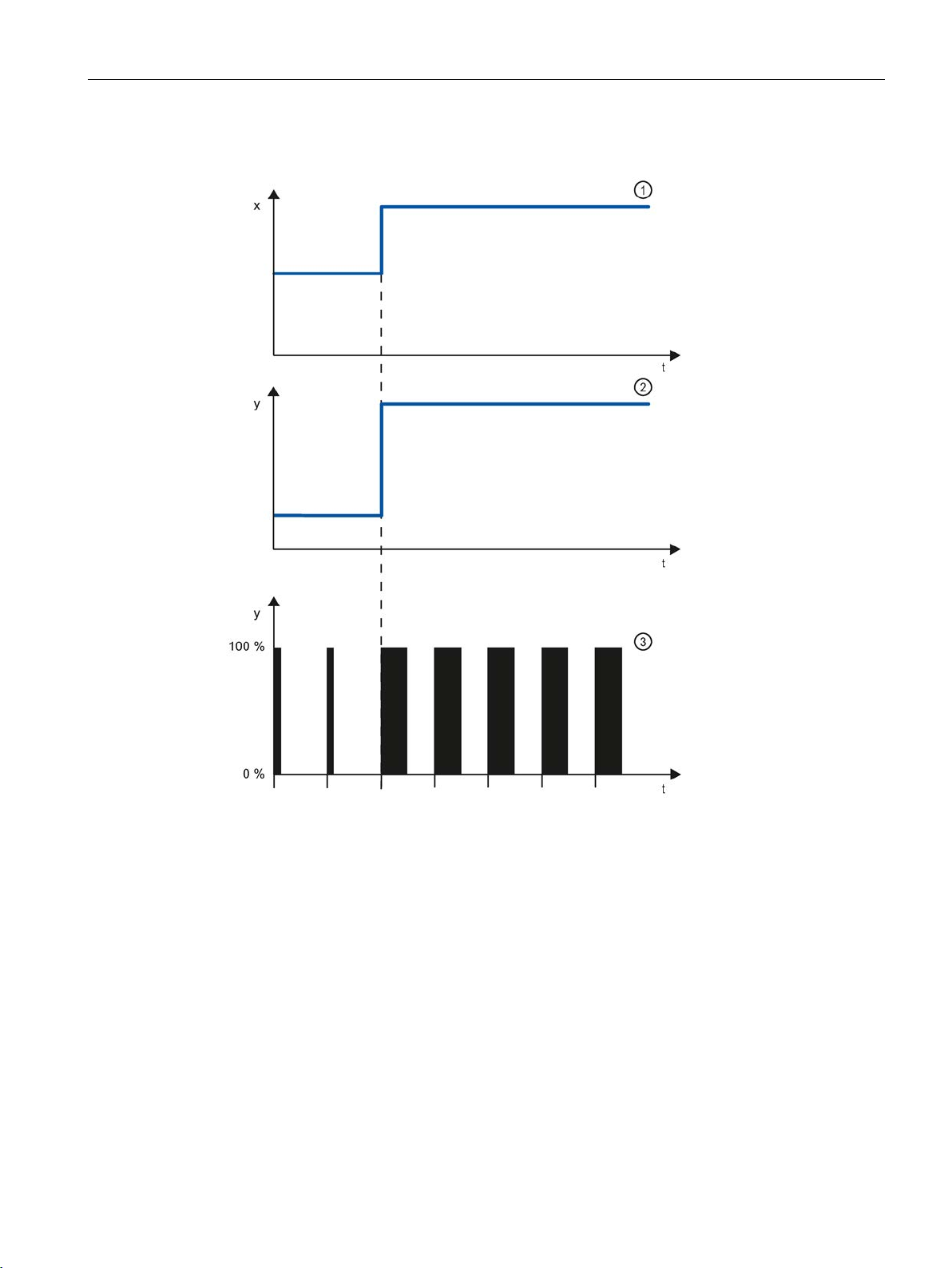
Step response of a proportional action controller
①
Control deviation
②
Output value of a continuous controller
③
Output value of a pulse controller
Equation for proportional action controller
2.6 Control Response at Different Feedback Structures
Output value and control deviation are directly proportional, meaning:
Output value = proportional gain × control deviation
y = GAIN × x
PID control
Function Manual, 03/2017, A5E35300227-AC
29
Page 30
Principles for control
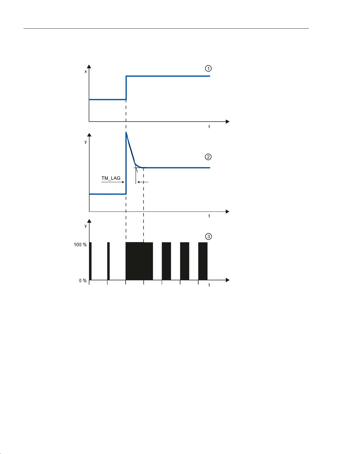
Step response of a PD-action controller
①
Control deviation
②
Output value of a continuous controller
③
Output value of a pulse controller
TM_LAG
Delay of the Derivative action
2.6 Control Response at Different Feedback Structures
PID control
30 Function Manual, 03/2017, A5E35300227-AC
Page 31

Principles for control
Equation for PD-action controller
2.6 Control Response at Different Feedback Structures
The following applies for the step response of the PD-action controller in the time range:
t = time interval since the step of the control deviation
The derivative action generates a output value as a function of the rate of change of the
process value. A derivative action by itself is not suitable for controlling because the output
value only follows a step of the process value. As long as the process value remains
constant, the output value will no longer change.
The response to disturbances of the derivative action is improved in combination with a
proportional action. Disturbances are not corrected completely. The good dynamic response
is advantageous. A well attenuated, non-oscillating response is achieved during approach
and setpoint change.
A controller with derivative action is not appropriate if a controlled system has pulsing
measured quantities, for example, in the case of pressure or flow control systems.
PID control
Function Manual, 03/2017, A5E35300227-AC
31
Page 32
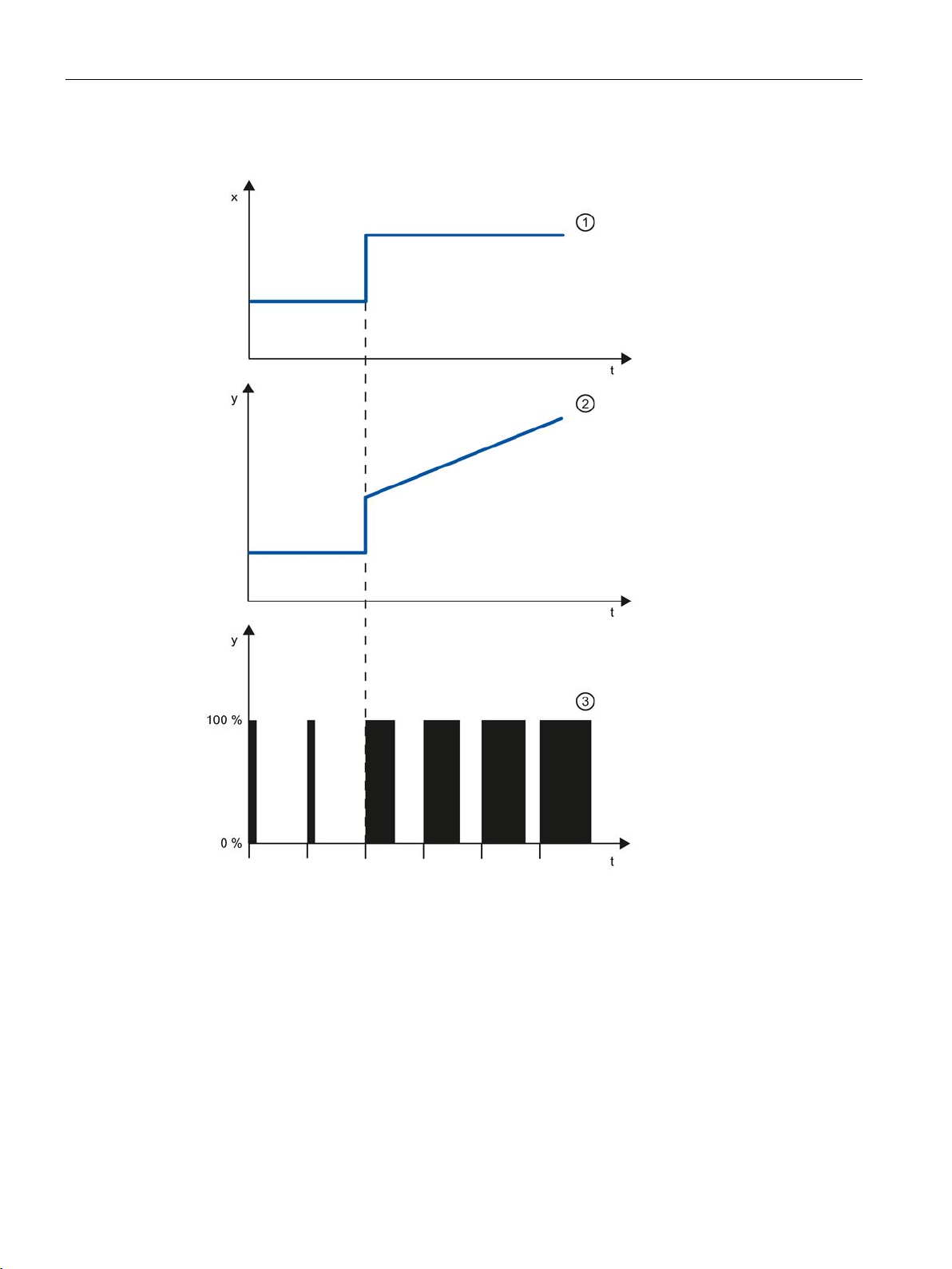
Principles for control
Step response of a PI-action controller
①
Control deviation
②
Output value of a continuous controller
③
Output value of a pulse controller
2.6 Control Response at Different Feedback Structures
An integral action in the controller adds the control deviation as a function of the time. This
means that the controller corrects the system until the control deviation is eliminated. A
sustained control deviation is generated at controllers with proportional action only. This
effect can be eliminated by means of an integral action in the controller.
In practical experience, a combination of the proportional, integral and derivative actions is
ideal, depending on the requirements placed on the control response. The time response of
the individual components can be described by the controller parameters proportional gain
GAIN, integral action time TI (integral action), and derivative action time TD (derivative
action).
PID control
32 Function Manual, 03/2017, A5E35300227-AC
Page 33

Principles for control
Equation for PI-action controller
2.6 Control Response at Different Feedback Structures
The following applies for the step response of the PI-action controller in the time range:
t = time interval since the step of the control deviation
PID control
Function Manual, 03/2017, A5E35300227-AC
33
Page 34
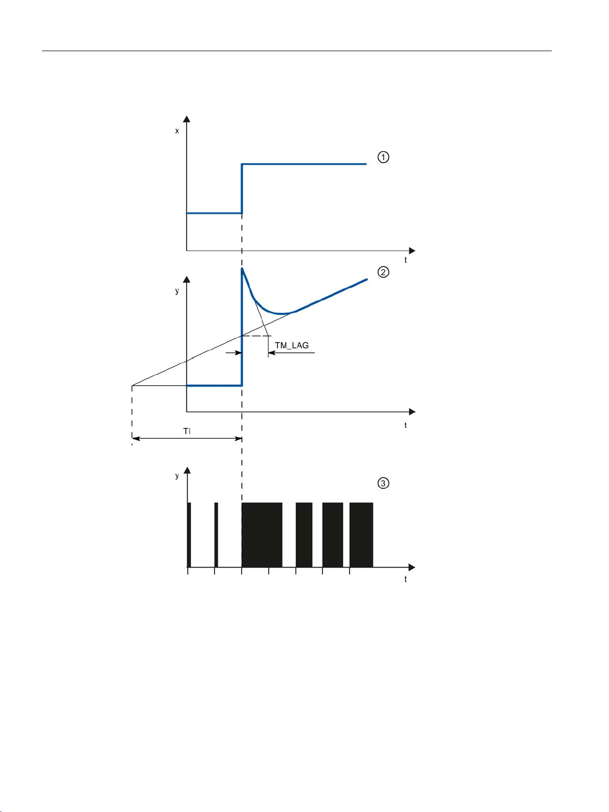
Principles for control
Step response of a PID controller
①
Control deviation
②
Output value of a continuous controller
③
Output value of a pulse controller
TM_LAG
Delay of the Derivative action
Ti
Integral action time
2.6 Control Response at Different Feedback Structures
PID control
34 Function Manual, 03/2017, A5E35300227-AC
Page 35
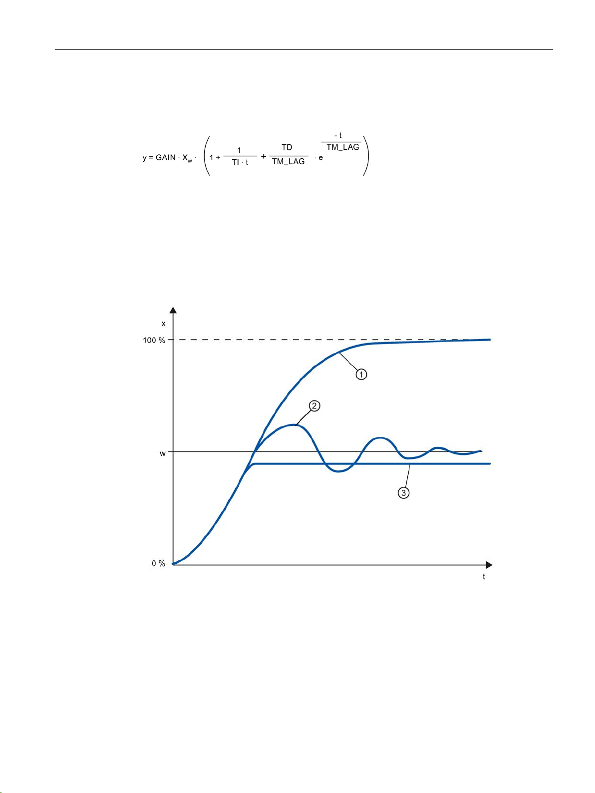
Principles for control
Equation for PID controller
Response of a controlled system with different controller structures
①
No controller
②
PID controller
③
PD-action controller
w
Setpoint
x
Process value
2.6 Control Response at Different Feedback Structures
The following applies for the step response of the PID controller in the time range:
t = time interval since the step of the control deviation
Most of the controller systems occurring in process engineering can be controlled by means
of a controller with PI-action response. In the case of slow controlled system with a large
dead time, for example temperature control systems, the control result can be improved by
means of a controller with PID action.
PID control
Function Manual, 03/2017, A5E35300227-AC
Controllers with PI and PID action have the advantage that the process value does not have
any deviation from the setpoint value after settling. The process value oscillates over the
setpoint during approach.
35
Page 36
Principles for control
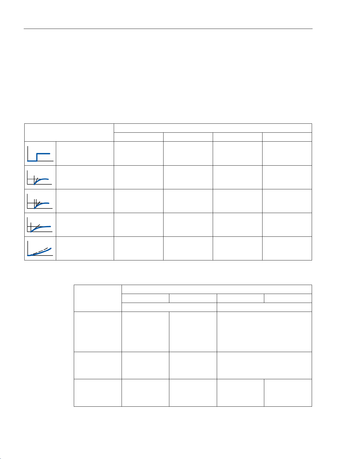
2.7
Selection of the controller structure for specified controlled systems
Selection of the Suitable Controller Structures
Controlled system
Controller structure
P
PD
PI
PID
Physical quantity
Controller structure
P
PD
PI
PID
Sustained control deviation
No sustained control deviation
with Tu/Tg < 0,1
usually too large
better
2.7 Selection of the controller structure for specified controlled systems
To achieve optimum control results, select a controller structure that is suitable for the
controlled system and that you can adapt to the controlled system within specific limits.
The table below provides an overview of suitable combinations of a controller structure and
controlled system.
With dead time only Unsuitable Unsuitable Suitable Unsuitable
PT1 with dead time Unsuitable Unsuitable Well suited Well suited
PT2 with dead time Unsuitable Suited conditionally Well suited Well suited
Higher order Unsuitable Unsuitable Suited conditionally Well suited
Not self-regulating Well suited Well suited Well suited Well suited
The table below provides an overview of suitable combinations of a controller structure and
physical quantity.
Temperature For low perfor-
mance requirements and
proportional action
controlled systems
Pressure Suitable, if the
delay time is inconsiderable
Flow rate Unsuitable, be-
cause required
GAIN range is
Well suited The most suitable controller structures
for high performance requirements
(except for specially adapted special
controllers)
Unsuitable The most suitable controller structures
for high performance requirements
(except for specially adapted special
controllers)
Unsuitable Suitable, but inte-
gral action controller alone often
Hardly required
PID control
36 Function Manual, 03/2017, A5E35300227-AC
Page 37

Principles for control
2.8
PID parameter settings
Rule of Thumb for the Parameter Setting
Controller structure
Setting
P
GAIN ≈ v
max
× Tu [° C ]
TI ≈ 4 × Tu [ min ]
TM_LAG ≈ 0.5 × TD[ min ]
TM_LAG ≈ 0.5 × TD[ min ]
TM_LAG ≈ 0.5 × TD[ min ]
2.8 PID parameter settings
Instead of v
PI GAIN ≈ 1.2 × v
PD GAIN ≈ 0.83 × v
TD ≈ 0.25 × v
PID GAIN ≈ 0.83 × v
TI ≈ 2 × Tu [ min ]
TD ≈ 0.4 × T
PD/PID GAIN ≈ 0.4 × v
TI ≈ 2 × Tu [ min ]
TD ≈ 0.4 × T
= ∆x / ∆t , you can use X
max
max
max
[ min ]
u
[ min ]
u
/ Tg.
× Tu [° C ]
max
× Tu [° C ]
max
× Tu [ min ]
× Tu [° C ]
max
× Tu [° C ]
max
In the case of controllers with PID structure the setting of the integral action time and
differential-action time is usually coupled with each other.
The ratio TI / TD lies between 4 and 5 and is optimal for most controlled systems.
Non-observance of the differential-action time TD is uncritical at PD controllers.
In the case of PI and PID controllers, control oscillations occur if the integral action time TI
has been select by more than half too small.
An integral action time that is too large slows down the settling times of disturbances. One
cannot expect that the control loops operate "optimally" after the first parameter settings.
Experience shows that adjusting is always necessary, when a system exists that is "difficult
to control" with T
PID control
Function Manual, 03/2017, A5E35300227-AC
/ Tg > 0.3.
u
37
Page 38

3
3.1
Overview of software controller
Technology objects and instructions
CPU
Library
Instruction
Technology object
Description
tuning
valves
S7-1200 V4.x
S7-1200 V4.x
S7-1200 ≥ V4.1
S7-1500/300/400
CONT_C
CONT_C
Continuous controller
grating behavior
portional behavior
pulse generator
integrating behavior
S7-300/400
TUN_EC
TUN_EC
Optimization of a continuous controller
For the configuration of a software controller, you need an instruction with the control
algorithm and a technology object. The technology object for a software controller
corresponds with the instance DB of the instruction. The configuration of the controller is
saved in the technology object. In contrast to the instance DBs of other instructions,
technology objects are not stored for the program resources, but rather under CPU >
Technology objects.
S7-1200 Compact PID PID_Compact V1.x PID_Compact V1.x Universal PID controller with integrated
S7-1200 PID_3Step V1.x PID_3Step V1.x PID controller with integrated tuning for
S7-1500
S7-1500
S7-1500 ≥ V1.7
PID basic func-
S7-1500/300/400 CONT_S CONT_S Step controller for actuators with inte-
S7-1500/300/400 PULSEGEN - Pulse generator for actuators with pro-
S7-1500/300/400 TCONT_CP TCONT_CP Continuous temperature controller with
S7-1500/300/400 TCONT_S TCONT_S Temperature controller for actuators with
S7-300/400 TUN_ES TUN_ES Optimization of a step controller
tions
PID Self Tuner
PID_Compact V2.x PID_Compact V2.x Universal PID controller with integrated
tuning
PID_3Step V2.x PID_3Step V2.x PID controller with integrated tuning for
valves
PID_Temp V1.x PID_Temp V1.x Universal PID temperature controller
with integrated tuning
PID control
38 Function Manual, 03/2017, A5E35300227-AC
Page 39

Configuring a software controller
CPU
Library
Instruction
Technology object
Description
tor
S7-300/400
LP_SCHED
-
Distribute controller calls
ation
S7-300/400
CRP_IN
-
Scale analog input signal
S7-300/400
CRP_OUT
-
Scale analog output signal
S7-300/400
DEAD_T
-
Delay output of input signal
cess value
S7-300/400
DIF - Differentiate input signals over time
S7-300/400
ERR_MON
Monitor control deviation
S7-300/400
INTEG
-
Integrate input signals over time
S7-300/400
LAG1ST
-
First-order delay element
S7-300/400
LAG2ND
-
Second-order delay element
S7-300/400
LIMALARM
-
Report limit values
S7-300/400
LIMITER
-
Limiting the manipulated variable
continuous controller
controller
S7-300/400
NONLIN
-
Linearize encoder signal
S7-300/400
NORM
-
Scale process value physically
controllers to 1 actuator
S7-300/400
PARA_CTL
-
Switch parameter sets
S7-300/400
PID - PID algorithm
tors
soak
S7-300/400
ROC_LIM
-
Limit rate of change
S7-300/400
SCALE_M
-
Scale process value
S7-300/400
SP_GEN
-
Specify setpoint manually
S7-300/400
SPLT_RAN
-
Split manipulated variable range
S7-300/400
SWITCH
-
Switch analog values
S7-300/400
LP_SCHED_M
-
Distribute controller calls
3.1 Overview of software controller
S7-300/400 Standard PID
Control
S7-300/400 PID_ES PID_ES Step controller for actuators with inte-
S7-300/400 Modular PID
S7-300/400 DEADBAND - Suppress small fluctuations to the pro-
S7-300/400 LMNGEN_C - Determine manipulated variable for
S7-300/400 LMNGEN_S - Determine manipulated variable for step
(PID Professional optional
package)
Control
(PID Professional optional
package)
PID_CP PID_CP Continuous controller with pulse genera-
grating behavior
A_DEAD_B - Filter interfering signal from control devi-
S7-300/400 OVERRIDE - Switch manipulated variable from 2 PID
S7-300/400 PUSLEGEN_M - Generate pulse for proportional actua-
S7-300/400 RMP_SOAK - Specify setpoint according to ramp /
PID control
Function Manual, 03/2017, A5E35300227-AC
39
Page 40

Configuring a software controller
3.2
Steps for the configuration of a software controller
Step
Description
1
Add technology object (Page 40)
3
Call instruction in the user program (Page 43)
4
Download technology object to device (Page 44)
5
Commission software controller (Page 45)
6
Save optimized PID parameters in the project (Page 45)
7
Comparing values (Page 47)
8
Display instances of a technology object (Page 71)
3.3
Add technology objects
Add technology object in the project navigator
Requirement
Procedure
3.2 Steps for the configuration of a software controller
All SW-controllers are configured according to the same scheme:
2 Configure technology object (Page 42)
When a technology object is added, an instance DB is created for the instruction of this
technology object. The configuration of the technology object is stored in this instance DB.
A project with a CPU has been created.
To add a technology object, proceed as follows:
1. Open the CPU folder in the project tree.
2. Open the "Technology objects" folder.
3. Double-click "Add new object".
The "Add new object" dialog box opens.
4. Click on the "PID" button.
All available PID-controllers for this CPU are displayed.
5. Select the instruction for the technology object, for example, PID_Compact.
6. Enter an individual name for the technology object in the "Name" input field.
7. Select the "Manual" option if you want to change the suggested data block number of the
instance DB.
8. Click "Further information" if you want to add own information to the technology object.
9. Confirm with "OK".
PID control
40 Function Manual, 03/2017, A5E35300227-AC
Page 41

Configuring a software controller
Result
Note
You can select the "Add new and open" check box at the bottom of the dialog box. This
opens the configuration of the technology object after adding has been completed.
3.3 Add technology objects
The new technology object has been created and stored in the project tree in the
"Technology objects" folder. The technology object is used if the instruction for this
technology object is called in a cyclic interrupt OB.
PID control
Function Manual, 03/2017, A5E35300227-AC
41
Page 42

Configuring a software controller
3.4
Configure technology objects
Inspector window of the programming editor
Configuration window
Symbols
The configuration contains default values and is complete
possible without further changes.
The configuration contains user-defined or automatically adjusted values and is complete
All input fields of the configuration contain valid values and at least one default setting was changed.
The configuration is incomplete or faulty
list box has a red background. When clicked, the roll-out error message indicates the cause of the error.
3.4 Configure technology objects
The properties of a technology object on a S7-1200 CPU can be configured in two ways.
● In the Inspector window of the programming editor
● In the configuration editor
The properties of a technology object on a S7-300/400 CPU can only be configured in the
configuration editor.
In the Inspector window of the programming editor you can only configure the parameters
required for operation.
The offline values of the parameters are also shown in online mode. You can only change
the online values in the commissioning window.
To open the Inspector window of the technology object, follow these steps:
1. Open the "Program blocks" folder in the project tree.
2. Double click the block (cyclic interrupt OB) in which you open the instruction of the SWcontroller.
The block is opened in the work area.
3. Click on the instruction of the SW-controller.
4. In the Inspector window, select the "Properties" and "Configuration" tabs consecutively.
For each technology object, there is a specific configuration window in which you can
configure all properties.
To open the configuration window of the technology object, follow these steps:
1. Open the "Technology objects" folder in the project tree.
2. Open the technology object in the project tree.
3. Double-click the "Configuration" object.
Icons in the area navigation of the configuration and in the Inspector window show additional
details about the completeness of the configuration:
.
The configuration exclusively contains default values. With these default values the use of the technology object is
At least one input field or a collapsible list contains no or one invalid value. The corresponding field or the drop-down
The properties of a technology object are described in detail in the section for the technology
object.
PID control
42 Function Manual, 03/2017, A5E35300227-AC
Page 43

Configuring a software controller
3.5
Call instruction in the user program
Requirement
Procedure
Result
3.5 Call instruction in the user program
The instruction of the software controller must be called in a cyclic interrupt OB. The
sampling time of the software controller is determined by the interval between the calls in the
cyclic interrupt OB.
The cyclic interrupt OB is created and the cycle time of the cyclic interrupt OB is correctly
configured.
Proceed as follows to call the instruction in the user program:
1. Open the CPU folder in the project tree.
2. Open the "Program blocks" folder.
3. Double-click the cyclic interrupt OB.
The block is opened in the work area.
4. Open the "Technology" group in the "Instructions" window and the "PID Control" folder.
The folder contains all instructions for software controllers that can be configured on the
CPU.
5. Select the instruction and drag it to your cyclic interrupt OB.
The "Call options" dialog box opens.
6. Select a technology object or type the name for a new technology object from the "Name"
list.
If the technology object does not exist yet, it is added. The instruction is added in the cyclic
interrupt OB. The technology object is assigned to this call of the instruction.
PID control
Function Manual, 03/2017, A5E35300227-AC
43
Page 44

Configuring a software controller
3.6
Downloading technology objects to device
Software (changes only)
Download PLC program to device and reset
Downloading retentive data to an S7-1200 or S7-1500 CPU
Note
The download and reset of the PLC program during ongoing system operation can result in
serious damages or injuries in the case of malfunction
Make sure that dangerous states cannot occur before you download and reset the PLC
program.
3.6 Downloading technology objects to device
A new or modified configuration of the technology object must be downloaded to the CPU for
the online mode. The following characteristics apply when downloading retentive data:
●
– S7-1200, S7-1500:
Retentive data is retained.
– S7-300/400:
Retentive data is updated immediately. CPU does not change to Stop.
●
– S7-1200, S7-1500:
Retentive data is updated at the next change from Stop to RUN. The PLC program
can only be downloaded completely.
– S7-300/400:
Retentive data is updated at the next change from Stop to RUN.
s or program errors.
Proceed as follows to download the retentive data:
1. Select the entry of the CPU in the project tree.
2. Select the command "Download and reset PLC program" from the "Online" menu.
– If you have not established an online connection yet, the "Extended download" dialog
opens. In this case, set all required parameters for the connection and click
"Download".
– If the online connection has been defined, the project data is compiled, if necessary,
and the dialog "Load preview" opens. This dialog displays messages and
recommends actions necessary for download.
3. Check the messages.
As soon as download is possible, the "Download" button becomes active.
4. Click on "Download".
The complete PLC program is downloaded and the "Load results" dialog opens. This
dialog displays the status and the actions after the download.
5. If the modules are to restart immediately after the download, select the check box "Start
all".
6. Close the dialog "Download results" with "Finish".
PID control
44 Function Manual, 03/2017, A5E35300227-AC
Page 45

Configuring a software controller
Result
3.7
Commissioning software controller
Procedure
3.8
Save optimized PID parameter in the project
Requirement
Procedure
Result
3.7 Commissioning software controller
The complete PLC program is downloaded to the device. Blocks that only exist online in the
device are deleted. By downloading all affected blocks and by deleting any blocks in the
device that are not required, you avoid inconsistencies between the blocks in the user
program.
The messages under "Info > General" in the Inspector window indicate whether the
download was successful.
To open the "Commissioning" work area of the technology object, follow these steps:
1. Open the "Technology objects" folder in the project tree.
2. Open the technology object in the project tree.
3. Double-click the "Commissioning" object.
The commissioning functions are specific for each controller and are described there.
The software controller is optimized in the CPU. Through this, the values in the instance-DB
on the CPU no longer agree with those in the project.
To update the PID parameter in the project with the optimized PID parameters, proceed as
follows:
● An online connection to the CPU is established and the CPU is in "RUN" mode.
● The functions of the commissioning window have been enabled by means of the "Start"
button.
1. Open the CPU folder in the project tree.
2. Open the "Technology objects" folder.
3. Open a technology object.
4. Double click on "Commissioning".
5. Click on the
6. Save the project.
The currently active PID parameters are stored in the project data. When reloading the
project data in the CPU, the optimized parameters are used.
PID control
Function Manual, 03/2017, A5E35300227-AC
icon "Upload PID parameters".
45
Page 46
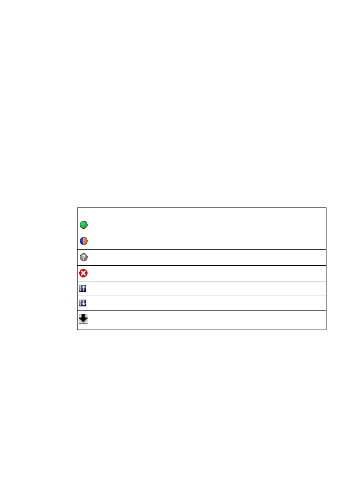
Configuring a software controller
3.9
Comparing values
3.9.1
Comparison display and boundary conditions
Icons and operator controls
Icon
Function
Boundary conditions
3.9 Comparing values
The "Compare values" function provides the following options:
● Comparison of configured start values of the project with the start values in the CPU and
the actual values
● Direct editing of actual values and the start values of the project
● Immediate detection and display of input errors with suggested corrections
● Backup of actual values in the project
● Transfer of start values of the project to the CPU as actual values
The following icons and operator controls are available:
The "Compare values" function is available for S7-1200 and S7-1500 without limitations.
The following limitation applies to S7-300 and S7-400:
In monitoring mode, an S7-300/S7-400 cannot transfer the start values to the CPU. These
values cannot be displayed online with "Compare values".
Start value PLC matches the configured Start value project
Start value PLC does not match the configured Start value project
The comparison of the Start value PLC with the configured Start value project cannot
be performed
At least one of the two comparison values has a process-related or syntax error.
Transfers actual values to the offline project
Transfers updated start values in the project to the CPU (initialize setting values)
Opens the "Compare values" dialog
The actual values of the technology object are displayed and can be changed directly.
PID control
46 Function Manual, 03/2017, A5E35300227-AC
Page 47

Configuring a software controller
3.9.2
Comparing values
Requirements
Procedure
Error detection
3.9 Comparing values
The procedure is shown in the following using "PID Parameters" as an example.
● A project with a software controller is configured.
● The project is downloaded to the CPU.
● The configuration dialog is open in the project navigator.
1. Open the desired software controller in the project navigation.
2. Double-click the "Configuration" object.
3. Navigate within the configuration window to the "PID Parameters" dialog.
4. Click the
The icons and operator controls (Page 46) of the "Compare values" function are shown
behind the parameters.
5. Click the desired parameter in the input box and change the parameter values manually
by entering them directly.
– If the background of the input box is gray, this value is a read-only value and cannot
be changed.
– To change the values in the "PID Parameters" dialog, enable manual entry by
selecting the "Enable manual entry" check box beforehand.
6. Click the
This dialog indicates two values of the parameter:
– Start value in CPU: The start value in the CPU is shown in the top part.
– Start value in the project: The configured start value in the project is shown in the
bottom part.
7. Enter the desired value in the input box for the project.
The input of incorrect values is detected. Corrections are suggested in this case.
icon to activate monitoring mode.
icon to open the dialog for the start values.
If you enter a value with incorrect syntax, a rollout containing the corresponding error
message opens below the parameter. The incorrect value is not applied.
If you enter a value that is incorrect for the process, a dialog opens containing the error
message and a suggested correction:
● Click "No" to accept this suggested correction and correct your input.
● Click "OK" to apply the incorrect value.
PID control
Function Manual, 03/2017, A5E35300227-AC
47
Page 48
Configuring a software controller
NOTICE
Malfunctions of the controller
Backing up actual values
Transferring project values to the CPU
CAUTION
Prevent personal injury and property damage!
3.9 Comparing values
Values incorrect for the process can result in controller malfunctions.
Click the icon to transfer the actual controller values to the start values of your configured
project.
Click the icon to transfer the configured values of your project to the CPU.
Downloading and resetting of the user program while the plant is operating may result in
significant property damage and severe personal injuries in the event of malfunctions or
program errors.
Make sure that dangerous states cannot occur before you download and reset the user
program.
PID control
48 Function Manual, 03/2017, A5E35300227-AC
Page 49
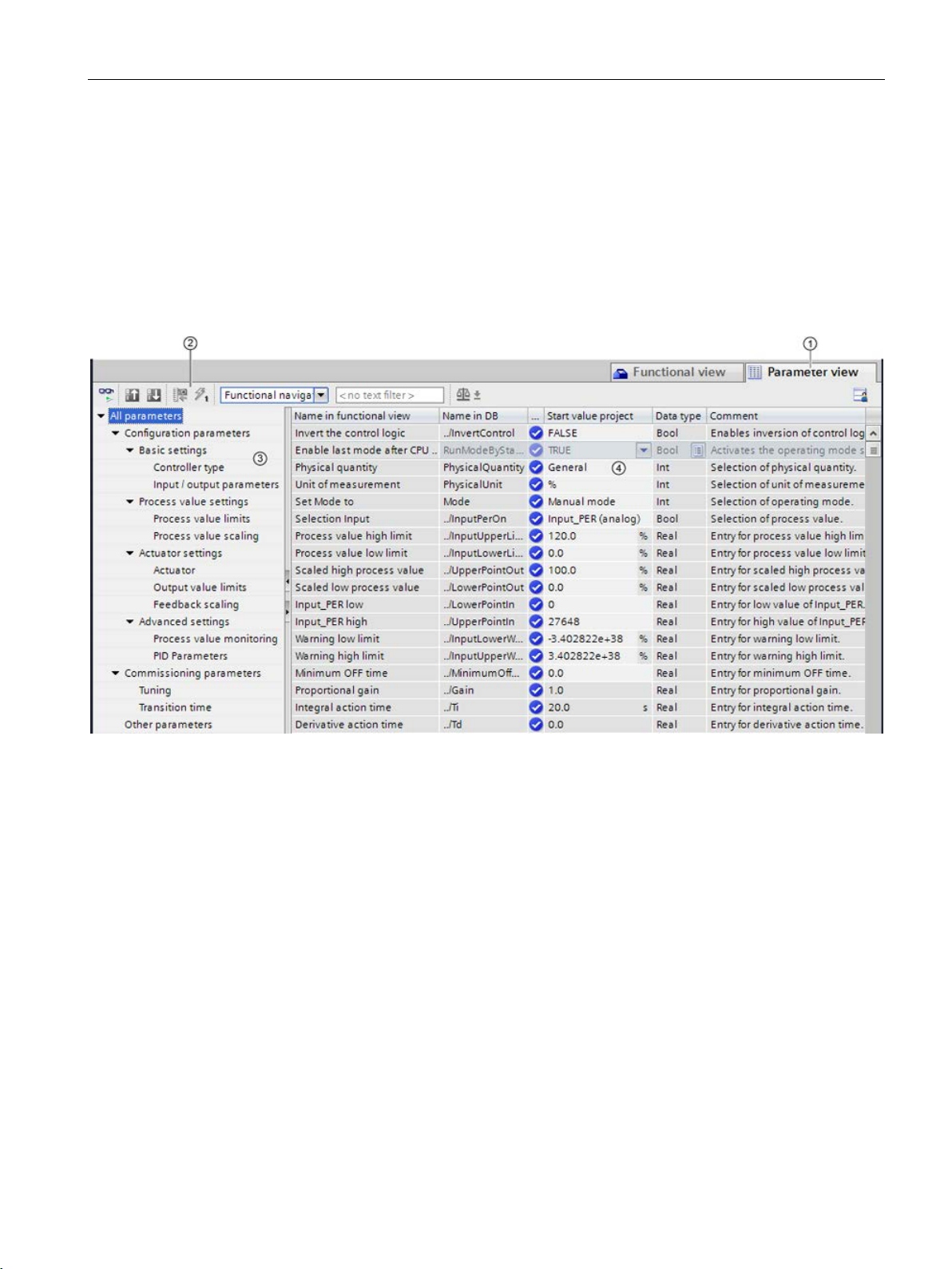
Configuring a software controller
3.10
Parameter view
3.10.1
Introduction to the parameter view
Function scope
:
3.10 Parameter view
The Parameter view provides you with a general overview of all relevant parameters of a
technology object. You obtain an overview of the parameter settings and can easily change
them in offline and online mode.
① "Parameter view" tab
② Toolbar (Page 51)
③ Navigation (Page 52)
④ Parameter table (Page 52)
The following functions are available for analyzing the parameters of the technology objects
and for enabling targeted monitoring and modification.
Display functions
● Display of parameter values in offline and online mode
● Display of status information of the parameters
● Display of value deviations and option for direct correction
● Display of configuration errors
● Display of value changes as a result of parameter dependencies
PID control
Function Manual, 03/2017, A5E35300227-AC
49
Page 50

Configuring a software controller
Validity
3.10 Parameter view
● Display of all memory values of a parameter: Start value PLC, Start value project, Monitor
value
● Display of the parameter comparison of the memory values of a parameter
Operator control functions:
● Navigation for quickly changing between the parameters and parameter structures.
● Text filter for faster searches for particular parameters.
● Sorting function for customizing the order of parameters and parameter groups to
requirements.
● Memory function for backing up structural settings of the Parameter view.
● Monitoring and modifying of parameter values online.
● Change display format of value.
● Function for saving a snapshot of parameter values of the CPU in order to capture
momentary situations and to respond to them.
● Function for applying a snapshot of parameter values as start values.
● Download of modified start values to the CPU.
● Comparison functions for comparing parameter values with one another.
The Parameter view described here is available for the following technology objects:
● PID_Compact
● PID_3Step
● PID_Temp
● CONT_C (S7-1500 only)
● CONT_S (S7-1500 only)
● TCONT_CP (S7-1500 only)
● TCONT_S (S7-1500 only)
● TO_Axis_PTO (S7-1200 Motion Control)
● TO_Positioning_Axis (S7-1200 Motion Control)
● TO_CommandTable_PTO (S7-1200 Motion Control)
● TO_CommandTable (S7-1200 Motion Control)
PID control
50 Function Manual, 03/2017, A5E35300227-AC
Page 51
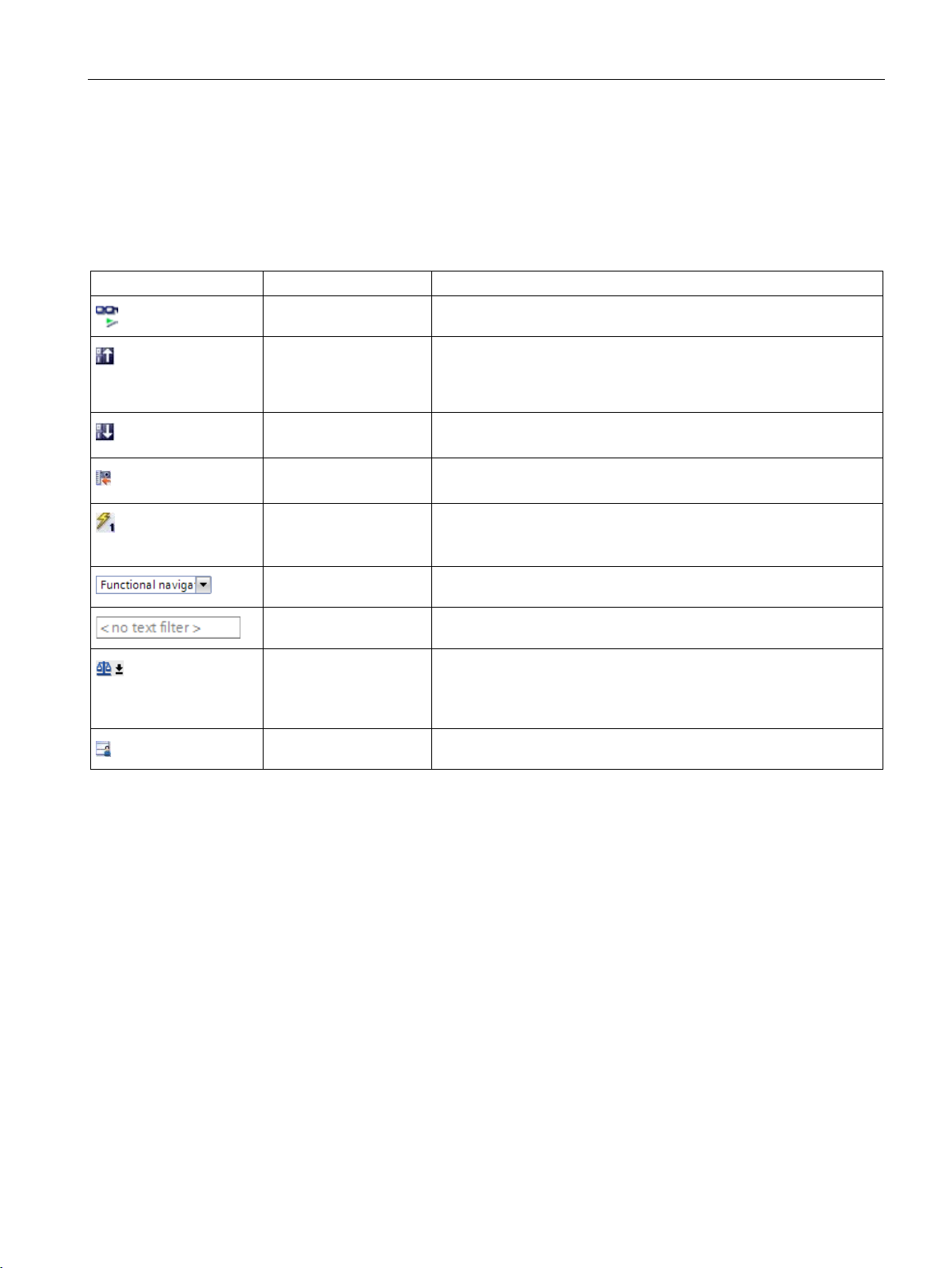
Configuring a software controller
3.10.2
Structure of the parameter view
3.10.2.1
Toolbar
Icon
Function
Explanation
snapshot as start values
Only in online mode for PID_Compact, PID_3Step and PID_Temp.
Only in online mode.
Only in online mode.
ture
Only in online mode.
navigation structure, activated table columns, etc.)
3.10 Parameter view
The following functions can be selected in the toolbar of the parameter view.
Monitor all Starts the monitoring of visible parameters in the active Parameter
view (online mode).
Create snapshot of
monitor values and
accept setpoints of this
Initialize setpoints Transfers the start values updated in the project to the CPU.
Create snapshot of
monitor values
Modify all selected parameters immediately
and once
Select navigation struc-
Applies the current monitor values to the “Snapshot” column and
updates the start values in the project.
Only in online mode for PID_Compact, PID_3Step and PID_Temp.
Applies the current monitor values to the “Snapshot” column.
This command is executed once and as quickly as possible without
reference to any particular point in the user program.
Toggles between functional navigation and data navigation.
Text filter... After entry of a character string: Display of all parameters containing
Selection of compare
values
Save window settings Saves your display settings for the Parameter view (e.g., selected
the specified string in one of the currently visible columns.
Selection of parameter values that are to be compared with one
another in online mode (Start value project, Start value PLC, Snapshot)
PID control
Function Manual, 03/2017, A5E35300227-AC
51
Page 52
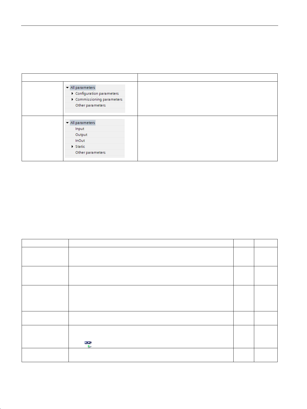
Configuring a software controller
3.10.2.2
Navigation
Navigation
Explanation
In the data navigation, the structure of the parameters is based on
3.10.2.3
Parameter table
Column
Explanation
Offline
Online
Name in functional
Name of the parameter in the functional view.
nology object.
X
X
The display field is empty for parameters that are not contained in the instance
DB / technology DB.
The display field is empty for parameters that are not contained in the instance
DB / technology DB.
see Status of configuration (offline) (Page 62)
button is selected.
Start value project
Configured start value in the project.
Error indication if entered values have a syntax or process-related error.
X
X
3.10 Parameter view
Functional navigation
Data navigation
Within the "Parameter view" tab, the following alternative navigation structures can be
selected.
In the functional navigation, the structure of the parameters is
based on the structure in the configuration dialog ("Functional
view" tab), commissioning dialog, and diagnostics dialog.
The last group "Other parameters" contains all other parameters
of the technology object.
the structure in the instance DB / technology DB.
The last group "Other parameters" contains the parameters that
are not contained in the instance DB / technology DB.
You can use the "Select navigation structure" drop-down list to toggle the navigation
structure.
The table below shows the meaning of the individual columns of the parameter table. You
can show or hide the columns as required.
● Column "Offline" = X: Column is visible in offline mode.
● Column "Online" = X: Column is visible in online mode (online connection to the CPU).
view
Full name in DB Complete path of the parameter in the instance DB / technology DB.
Name in DB Name of the parameter in the instance DB / technology DB.
Status of configuration
Compare result Result of the "Compare values" function.
The display field is empty for parameters that are not configured via the tech-
If the parameter is part of a structure or UDT, the prefix ". ./" is added.
Display of the completeness of the configuration using status symbols.
This column is shown if there is an online connection and the "Monitor all"
X X
X X
X
X
PID control
52 Function Manual, 03/2017, A5E35300227-AC
Page 53
Configuring a software controller
Column
Explanation
Offline
Online
y field is empty for parameters that are not contained in the instance
DB / technology DB.
Error indication if values have a process-related error.
Error indication if values have a process-related error.
Error indication if values have a process-related error.
Error indication if entered values have a syntax or process-related error.
This column is displayed together with the "Modify value" column.
online.
The display field is empty for parameters that are not contained in the instance
DB / technology DB.
is switched off.
Accessible from HMI
Indicates whether the HMI can access this parameter during runtime.
X
X
default.
Comment
Brief description of the parameter.
X
X
See also
3.10 Parameter view
Default value Value that is pre-assigned to the parameter.
The displa
Snapshot Snapshot of the current values in the CPU (monitor values).
Start value PLC Start value in the CPU.
This column is shown if there is an online connection and the "Monitor all"
button
Monitor value Current value in the CPU.
This column is shown if there is an online connection and the "Monitor all"
button
Modify value Value that is to be used to change the monitor valuet.
This column is shown if there is an online connection and the "Monitor all"
button
Selection for transmission
Minimum value Minimum process-related value of the parameter.
Maximum value Maximum process-related value of the parameter.
Setpoint Designates the parameter as a setpoint. These parameters can be initialized
Selection of the Modify values that are to be transmitted using the "Modify all
selected parameters immediately and once" button.
If the minimum value is dependent on other parameters, it is defined:
• Offline: By the Start value project.
• Online: By the Monitor values.
If the maximum value is dependent on other parameters, it is defined:
• Offline: By the Start value project.
• Online: By the Monitor values.
is selected.
is selected.
is selected.
X X
X X
X
X
X
X
X X
X X
X X
Data type Data type of the parameter.
Retain Designates the value as a retentive value.
The values of retentive parameters are retained even after the voltage supply
Visible in HMI Indicates whether the parameter is visible in the selection list of the HMI by
Comparing values (Page 46)
PID control
Function Manual, 03/2017, A5E35300227-AC
X X
X X
X X
53
Page 54

Configuring a software controller
3.10.3
Opening the parameter view
Requirement
Procedure
Result
See also
3.10 Parameter view
The technology object has been added in the project tree, i.e., the associated instance DB /
technology DB of the instruction has been created.
1. Open the "Technology objects" folder in the project tree.
2. Open the technology object in the project tree.
3. Double-click the "Configuration" object.
4. Select the "Parameter view" tab in the top right corner.
The Parameter view opens. Each displayed parameter is represented by one row in the
parameter table.
The displayable parameter properties (table columns) vary depending on whether you are
working with the Parameter view in offline or online mode.
In addition, you can selectively display and hide individual table columns.
Default setting of the parameter view (Page 55)
PID control
54 Function Manual, 03/2017, A5E35300227-AC
Page 55

Configuring a software controller
3.10.4
Default setting of the parameter view
Default settings
Show and hide columns
3.10 Parameter view
To enable you to work efficiently with the Parameter view, you can customize the parameter
display and save your settings.
The following customizations are possible and can be saved:
● Show and hide columns
● Change column width
● Change order of the columns
● Toggle navigation
● Select parameter group in the navigation
● Selection of compare values
To show or hide columns in the parameter table, follow these steps:
1. Position the cursor in the header of the parameter table.
2. Select the "Show/Hide" command in the shortcut menu.
The selection of available columns is displayed.
3. To show a column, select the check box for the column.
4. To hide a column, clear the check box for the column.
or
1. Position the cursor in the header of the parameter table.
2. Select the "Show all columns" command in the shortcut menu if all columns of the offline
or online mode are to be displayed.
Some columns can only be displayed in online mode: see Parameter table (Page 52).
PID control
Function Manual, 03/2017, A5E35300227-AC
55
Page 56

Configuring a software controller
Change column width
Change order of the columns
Toggle navigation
Select parameter group in the navigation
3.10 Parameter view
To customize the width of a column so that all texts in the rows can be read, follow these
steps:
1. Position the cursor in the header of the parameter table to the right of the column to be
customized until the shape of the cursor changes to a cross.
2. Then double-click this location.
or
1. Open the shortcut menu on the header of the parameter table.
2. Click
– "Optimize column width" or
– "Optimize width of all columns".
If the column width setting is too narrow, the complete content of individual fields are shown
if you hover the cursor briefly over the relevant field.
The columns of the parameter table can be arranged in any way.
To change the order of the columns, follow these steps:
1. Click on the column header and use a drag-and-drop operation to move it to the desired
location.
When you release the mouse button, the column is anchored to the new position.
To toggle the display form of the parameters, follow these steps:
1. Select the desired navigation in the “Select navigation structure” drop-down list.
– Data navigation
– Functional navigation
See also Navigation (Page 52).
Within the selected navigation, you choose between the “All parameters” display or the
display of a subordinate parameter group of your choice.
1. Click the desired parameter group in the navigation.
The parameter table only displays the parameters of the parameter group.
PID control
56 Function Manual, 03/2017, A5E35300227-AC
Page 57

Configuring a software controller
Selection of compare values (online)
Saving the default setting of the Parameter view
3.10.5
Working with the parameter view
3.10.5.1
Overview
Function/action
Offline
Online
Filtering the parameter table (Page 58)
X
X
Sorting the parameter table (Page 59)
X
X
Transferring parameter data to other editors (Page 59)
X
X
Editing start values in the project (Page 60)
X
X
Monitoring values online in the parameter view (Page 63)
X Create snapshot of monitor values (Page 65)
X
Modifying values (Page 65)
X
Comparing values (Page 67)
X
Applying values from the online program as start values (Page 68)
X Initializing setpoints in the online program (Page 70)
X
3.10 Parameter view
To set the compare values for the “Compare values” function, follow these steps:
1. Select the desired compare values in the “Selection of compare values” drop-down list.
– Start value project / Start value PLC
– Start value project / Snapshot
– Start value PLC / Snapshot
The “Start value project / Start value PLC” option is set by default.
To save the above customizations of the Parameter view, follow these steps:
1. Customize the Parameter view according to your requirements.
2. Click the “Save window settings” button
at the top right of the Parameter view.
The following table provides an overview of the functions of the Parameter view in online and
offline mode described in the following.
● Column "Offline" = X: This function is possible in offline mode.
● Column "Online" = X: This function is possible in online mode.
Indicating errors (Page 60) X X
Status of configuration (offline) (Page 62) X
PID control
Function Manual, 03/2017, A5E35300227-AC
57
Page 58

Configuring a software controller
3.10.5.2
Filtering the parameter table
With the text filter
With the subgroups of the navigation
3.10 Parameter view
You can filter the parameters in the parameter table in the following ways:
● With the text filter
● With the subgroups of the navigation
Both filter methods can be used simultaneously.
Texts that are visible in the parameter table can be filtered. This means only texts in
displayed parameter rows and columns can be filtered.
1. Enter the desired character string for filtering in the “Text filter...” input box.
The parameter table displays only the parameters containing the character string.
The text filtering is reset.
● When another parameter group is selected in the navigation.
● When navigation is changed from data navigation to functional navigation, or vice versa.
1. Click the desired parameter group in the navigation, e.g., "Static".
The parameter table only shows the static parameters. You can select further subgroups
for some groups of the navigation.
2. Click “All parameters” in the navigation if all parameters are to be shown again.
PID control
58 Function Manual, 03/2017, A5E35300227-AC
Page 59

Configuring a software controller
3.10.5.3
Sorting the parameter table
Sorting by column
Result
3.10.5.4
Transferring parameter data to other editors
3.10 Parameter view
The values of the parameters are arranged in rows. The parameter table can be sorted by
any displayed column.
● In columns containing numerical values, sorting is based on the magnitude of the
numerical value.
● In text columns, sorting is alphabetical.
1. Position the cursor in the header cell of the desired column.
The background of this cell turns blue.
2. Click the column header.
The entire parameter table is sorted by the selected column. A triangle with tip facing up
appears in the column header.
Clicking the column header again changes the sorting as follows:
● Symbol “▲”: Parameter table is sorted in ascending order.
● Symbol “▼”: Parameter table is sorted in descending order.
● No symbol: The sorting is removed again. The parameter table assumes the default
display.
The “../“ prefix in the “Name in DB” column is ignored when sorting.
After selecting an entire parameter row of the parameter table, you can use the following:
● Drag-and-drop
● <Ctrl+C>/<Ctrl+V>
● Copy/Paste via shortcut menu
Transfer parameters to the following editors of the TIA Portal:
● Program editor
● Watch table
● Signal table for trace function
The parameter is inserted with its full name: See information in “Full name in DB” column.
PID control
Function Manual, 03/2017, A5E35300227-AC
59
Page 60

Configuring a software controller
3.10.5.5
Indicating errors
Error indication
Compilation error
3.10.5.6
Editing start values in the project
Boundary conditions
3.10 Parameter view
Parameter assignment errors that result in compilation errors (e.g., limit violation) are
indicated in the Parameter view.
Every time a value is input in the Parameter view, a check is made for process-related and
syntax errors and the result is indicated.
Bad values are indicated by:
● Red error symbol in the "Status of configuration" (offline mode) or "Compare result"
(online mode, depending on the selected comparison type) columns
and/or
● Table field with red background
If you click the bad field, a roll-out error message appears with information of the
permissible value range or the required syntax (format)
From the error message of the compiler, you can directly open the Parameter view
(functional navigation) containing the parameter causing the error in situations where the
parameter is not displayed in the configuration dialog.
With the Parameter view, you can edit the start values in the project in offline mode and
online mode.
● You make value changes in the “Start value project” column of the parameter table.
● In the “Status of configuration” column of the parameter table, the progress of the
● If other parameters depend on the parameter whose start value was changed, the start
● If a parameter of a technology object is not editable, it is also not editable in the
configuration is indicated by the familiar status symbols from the configuration dialog of
the technology object.
value of the dependent parameters are also adapted.
parameter view. The ability to edit a parameter can also depend on the values of other
parameters.
PID control
60 Function Manual, 03/2017, A5E35300227-AC
Page 61

Configuring a software controller
Defining new start values
Error indication
Correcting bad start values
3.10 Parameter view
To define start values for parameters in the Parameter view, follow these steps:
1. Open the Parameter view of the technology object.
2. Enter the desired start values in the "Start value project" column. The value must match
the data type of the parameter and must not exceed the value range of the parameter.
The limits of the value range can be seen in the “Maximum value” and “Minimum value”
columns.
The "Status of configuration" column indicates the progress of the configuration with colored
symbols.
See also Status of configuration (offline) (Page 62)
Following adaptation of the start values and downloading of the technology object to the
CPU, the parameters take the defined value at startup if they are not declared as retentive
(“Retain” column).
When a start value is input, a check is made for process-related and syntax errors and the
result is indicated.
Bad start values are indicated by:
● Red error symbol in the "Status of configuration" (offline mode) or "Compare result"
(online mode, depending on the selected comparison type) columns
and/or
● Red background in the “Start value project” field
If you click on the bad field, a roll-out error message appears with information of the
permissible value range or the necessary syntax (format)
1. Correct bad start values using information from the roll-out error message.
Red error symbol, red field background, and roll-out error message are no longer
displayed.
The project cannot be successfully compiled unless the start values are error-free.
PID control
Function Manual, 03/2017, A5E35300227-AC
61
Page 62
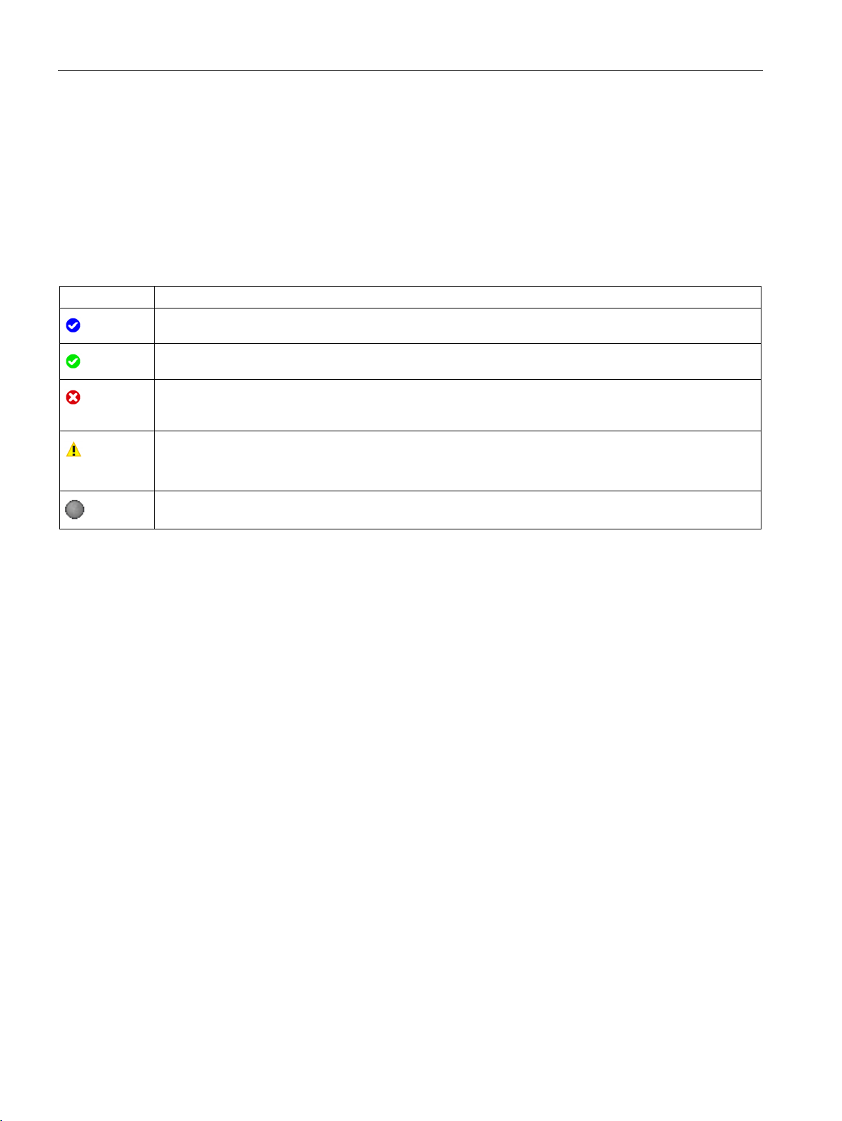
Configuring a software controller
3.10.5.7
Status of configuration (offline)
Symbol
Meaning
been defined by the user.
error.
The input box has a yellow background.
Symbol in the navigation
See also
3.10 Parameter view
The status of the configuration is indicated by icons:
● In the “Status of configuration” column in the parameter table
● In the navigation structure of the functional navigation and data navigation
Symbol in “Status of configuration” column
The start value of the parameter corresponds to the default value and is valid. A start value has not yet
The start value of the parameter contains a value defined by the user or an automatically adjusted value.
The start value is different than the default value. The start value is error-free and valid.
The start value of the parameter is invalid (syntax or process-related error).
The input box has a red background. When clicked, the roll-out error message indicates the cause of the
Only for S7-1200 Motion Control:
The start value of the parameter is valid but contains warnings.
The parameter is not relevant in the current configuration.
The symbols in the navigation indicate the progress of the configuration in the same way as
in the configuration dialog of the technology object.
Configure technology objects (Page 42)
PID control
62 Function Manual, 03/2017, A5E35300227-AC
Page 63

Configuring a software controller
3.10.5.8
Monitoring values online in the parameter view
Requirements
Procedure
Display
3.10 Parameter view
You can monitor the values currently taken by the parameters of the technology object in the
CPU (monitor values) directly in the Parameter view.
● There is an online connection.
● The technology object is downloaded to the CPU.
● The program execution is active (CPU in "RUN").
● The Parameter view of the technology object is open.
1. Start the monitoring by clicking .
As soon as the Parameter view is online, the following columns are additionally
displayed:
– Compare result
– Start value PLC
– Monitor value
– Modify value
– Selection for transmission
The "Monitor value" column shows the current parameter values on the CPU.
Meaning of the additional columns: see Parameter table (Page 52)
2. Stop the monitoring by clicking
All columns that are only available online have an orange background:
● Values in light-orange cells
● Values in cells with a dark orange background
again.
can be changed.
cannot be changed.
PID control
Function Manual, 03/2017, A5E35300227-AC
63
Page 64

Configuring a software controller
3.10.5.9
Change display format of value
Requirements
Procedure
Note
To change the display format of a certain data type in multiple table rows, sort the Parameter
view by this data type. Then select the first and last table row with this data type while
keeping the <Shift> key pressed
3.10 Parameter view
The display format of the value can be selected via the shortcut menu of a table row in the
Parameter view of the technology object.
The display format of the following values can be changed both in online mode and in offline
mode:
● Start value project
● Start value PLC
● Maximum value
● Minimum value
● Snapshot
● Monitor value
● Default value
● Modify value
The set display format applies to all values of the table row.
The following display formats of the value can be changed:
● Default
● Hex
● Octal
● Bin
● Dec (+/-)
● DEC
Depending on the parameter selected in the parameter view, only the supported display
formats can be selected.
● The Parameter view of the technology object is open.
To change the display format of the value, proceed as follows:
1. Select one or more table rows in which you want to change the display format.
2. Select the "Display format" command in the shortcut menu.
3. Select the desired display format.
and change the display format for the selected table rows.
PID control
64 Function Manual, 03/2017, A5E35300227-AC
Page 65

Configuring a software controller
3.10.5.10
Create snapshot of monitor values
Requirements
Procedure
Result
3.10.5.11
Modifying values
DANGER
3.10 Parameter view
You can back up the current values of the technology object on the CPU (monitor values)
and display them in the Parameter view.
● There is an online connection.
● The technology object is downloaded to the CPU.
● The program execution is active (CPU in "RUN").
● The Parameter view of the technology object is open.
● The “Monitor all” button
To show the current parameter values, follow these steps:
1. In the Parameter view, click the “Create snapshot of monitor values" icon
The current monitor values are transferred once to the "Snapshot" column of the parameter
table.
is selected.
.
You can analyze the values "frozen" in this way while the monitor values continue to be
updated in the "Monitor values" column.
With the Parameter view, you can modify values of the technology object in the CPU.
You can assign values to the parameter once (Modify value) and modify them immediately.
The modify request is executed as quickly as possible without reference to any particular
point in the user program.
Danger when modifying:
Changing the parameter values while the plant is operating may result in severe damage to
property and personal injury in the event of malfunctions or program errors.
Make sure that dangerous states cannot occur before you use the "Modify" function.
PID control
Function Manual, 03/2017, A5E35300227-AC
65
Page 66

Configuring a software controller
Requirements
Procedure
Error indication
Bad modify values
cannot
3.10 Parameter view
● There is an online connection.
● The technology object is downloaded to the CPU.
● The program execution is active (CPU in "RUN").
● The Parameter view of the technology object is open.
● The “Monitor all” button
● The parameter can be modified (associated field in the "Modify value" column has a light-
orange background).
To modify parameters immediately, follow these steps:
1. Enter the desired modify values in the “Modify values” column of the parameter table.
2. Check whether the check box for modifying is selected in the "Select for transmission"
column.
The modify values and associated check boxes of dependent parameters are
automatically adapted at the same time.
3. Click the “Modify all selected parameters immediately and once” icon
The selected parameters are modified once and immediately with the specified values and
can be monitored in the "Modify values" column. The check boxes for modifying in the
"Selection for transmission" column are automatically cleared after the modify request is
complete.
When a start value is input, a check is made immediately for process-related and syntax
errors and the result is indicated.
is selected.
.
Bad start values are indicated by:
● Red background in the “Modify value” field
and
● If you click the bad field, a roll-out error message appears with information of the
permissible value range or the necessary syntax (format)
● Modify values with process-related errors can be transmitted.
● Modify values with syntax errors
PID control
66 Function Manual, 03/2017, A5E35300227-AC
be transmitted.
Page 67

Configuring a software controller
3.10.5.12
Comparing values
Requirements
Procedure
3.10 Parameter view
You can use comparison functions to compare the following memory values of a parameter:
● Start value project
● Start value PLC
● Snapshot
● There is an online connection.
● The technology object is downloaded to the CPU.
● The program execution is active (CPU in "RUN").
● The Parameter view of the technology object is open.
● The “Monitor all” button
To compare the start values on the various target systems, follow these steps:
1. Click the "Selection of compare values" icon
is selected.
.
A selection list containing the comparison options opens:
– Start value project - Start value PLC (default setting)
– Start value project - Snapshot
– Start value PLC - Snapshot
2. Select the desired comparison option.
The selected comparison option is executed as follows:
– A scales symbol appears in the header cells of the two columns selected for
comparison.
– Symbols are used in the "Compare result" column to indicate the result of the
comparison of the selected columns.
PID control
Function Manual, 03/2017, A5E35300227-AC
67
Page 68
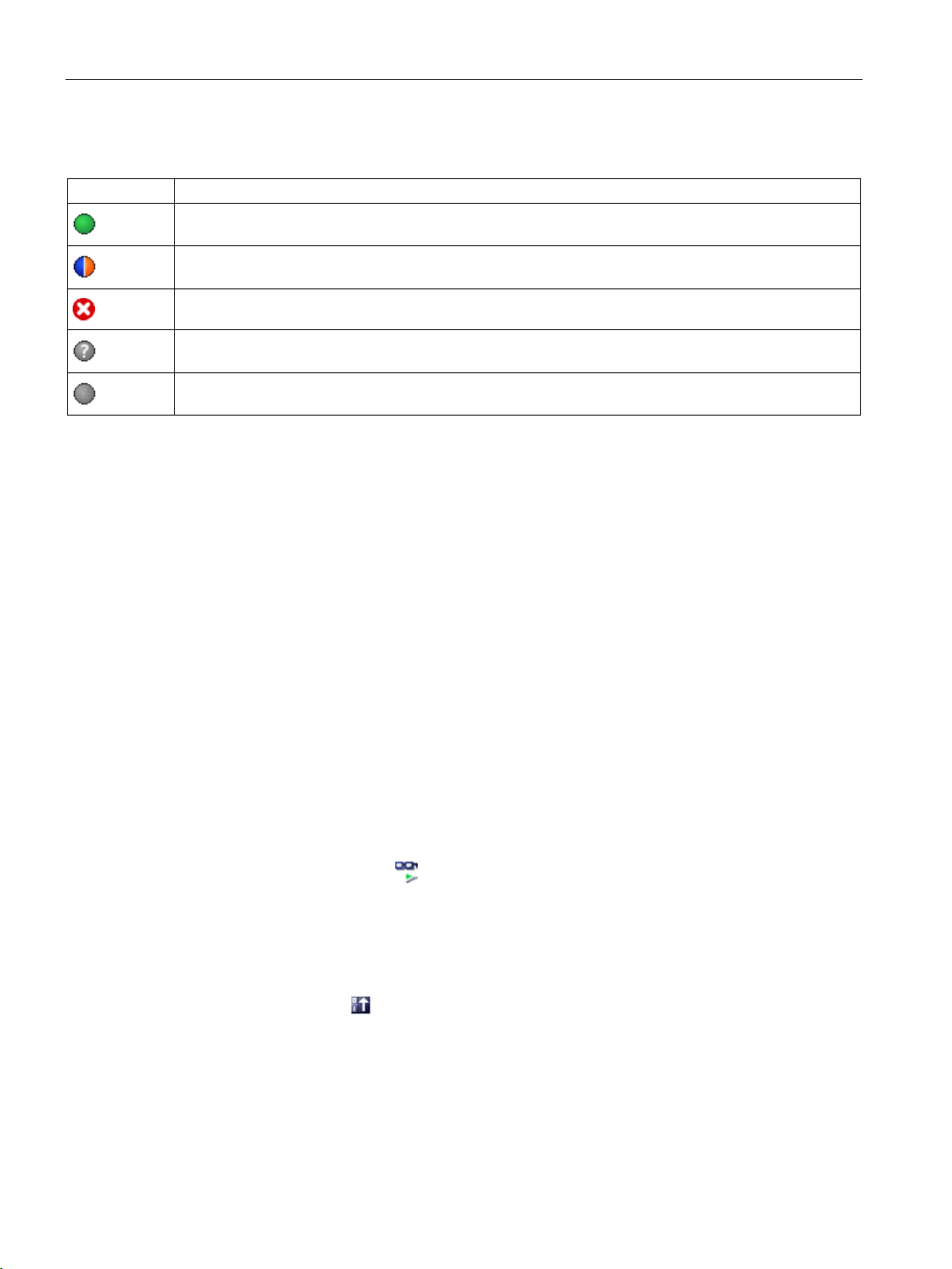
Configuring a software controller
Symbol in "Compare result" column
Symbol
Meaning
Symbol in the navigation
3.10.5.13
Applying values from the online program as start values
Requirements
Procedure
3.10 Parameter view
The compare values are equal and error-free.
The compare values are not equal and error-free.
At least one of the two compare values has a process-related or syntax error.
The comparison cannot be performed. At least one of the two comparison values is not available (e.g.
snapshot).
Comparison of the value is inappropriate since it is not relevant in one of the configurations.
The symbols are shown in the same way in the navigation if the comparison result applies to
at least one of the parameters below the displayed navigation structure.
In order to apply optimized values from the CPU to the project as start values, you create a
snapshot of the monitor values. Values of the snapshot marked as a "Setpoint" are then
applied to the project as start values.
● The technology object is of type "PID_Compact" or "PID_3Step".
● There is an online connection.
● The technology object is downloaded to the CPU.
● The program execution is active (CPU in "RUN").
● The Parameter view of the technology object is open.
● The “Monitor all” button
is selected.
To apply optimized values from the CPU, follow these steps:
1. Click the "Create snapshot of monitor values and accept setpoints of this snapshot as
start values" icon
.
PID control
68 Function Manual, 03/2017, A5E35300227-AC
Page 69

Configuring a software controller
Result
Note
Applying values of individual parameters
You can also apply the values of individual parameters that are not marked as a setpoint
from the "Snapshot" column to the "Start values project" column. To do so, copy the values
and insert them into the "Start value project" column using the "Copy" and "
commands in the shortcut menu.
3.10 Parameter view
The current monitor values are applied to the "Snapshot" column and their setpoints are
copied to the "Start value project" column as new start values.
Paste"
PID control
Function Manual, 03/2017, A5E35300227-AC
69
Page 70

Configuring a software controller
3.10.5.14
Initializing setpoints in the online program
DANGER
Danger when changing parameter values
Requirements
Procedure
Result
3.10 Parameter view
You can initialize all parameters that are marked as a "Setpoint" in the Parameter view with
new values in the CPU in one step. In so doing, the start values are downloaded from the
project to the CPU. The CPU remains in "RUN" mode.
To avoid data loss on the CPU during a cold restart or warm restart, you must also download
the technology object to the CPU.
Changing the parameter values while the plant is operating may result in severe damage to
property and personal injury in the event of malfunctions or program errors.
Make sure that dangerous states cannot occur before you reinitialize the setpoints.
● The technology object is of type "PID_Compact" or "PID_3Step".
● There is an online connection.
● The technology object is downloaded to the CPU.
● The program execution is active (CPU in "RUN").
● The Parameter view of the technology object is open.
● The “Monitor all” button
is selected.
● The parameters marked as a "Setpoint" have a "Start value project" that is free of
process-related and syntax errors
To initialize all setpoints, follow these steps:
1. Enter the desired values in the "Start value project" column.
Ensure that the start values are free of process-related and syntax errors.
2. Click the "Initialize setpoints" icon
.
The setpoints in the CPU are initialized with the start values from the project.
PID control
70 Function Manual, 03/2017, A5E35300227-AC
Page 71

Configuring a software controller
3.11
Display instance DB of a technology object.
Procedure
3.11 Display instance DB of a technology object.
An instance DB, in which the parameter and static variables are saved, is created for each
technology object.
To display the instance DB of a technology object, proceed as follows:
1. Open the CPU folder in the project tree.
2. Open the "Technology objects" folder.
3. Highlight a technology object.
4. Select the command "Open DB editor" in the shortcut menu.
PID control
Function Manual, 03/2017, A5E35300227-AC
71
Page 72

4
4.1
Technology object PID_Compact
Proportional
I
D
Additional information
FAQ
The technology object PID_Compact provides a continuous PID controller with integrated
optimization. You can alternatively configure a pulse controller. Both manual and automatic
mode are possible.
PID-Compact continuously acquires the measured process value within a control loop and
compares it with the required setpoint. From the resulting control deviation, the instruction
PID_Compact calculates an output value by which the process value is adapted as quickly
and stable as possible to the setpoint. The output value for the PID controller consists of
three actions:
●
The proportional action of the output value increases in proportion to the control
deviation.
●
The integral action of the output value increases until the control deviation has been
balanced.
●
The derivative action increases with the rate of change of control deviation. The process
value is corrected to the setpoint as quickly as possible. The derivative action will be
reduced again if the rate of change of control deviation drops.
The instruction PID_Compact calculates the proportional, integral and derivative parameters
for your controlled system during pretuning. Fine tuning can be used to tune the parameters
further. You do not need to manually determine the parameters.
● Overview of software controller (Page 38)
● Add technology objects (Page 40)
● Configure technology objects (Page 42)
● Configuring PID_Compact V2 (Page 73)
action
action
action
● Configuring PID_Compact V1 (Page 96)
For more information, see the following FAQs in the Siemens Industry Online Support:
● Entry ID 79047707 (https://support.industry.siemens.com/cs/ww/en/view/79047707)
PID control
72 Function Manual, 03/2017, A5E35300227-AC
Page 73

Using PID_Compact
4.2
PID_Compact V2
4.2.1
Configuring PID_Compact V2
4.2.1.1
Basic settings V2
Introduction V2
Setpoint, process value and output value
4.2 PID_Compact V2
Configure the following properties of the "PID_Compact" technology object under "Basic
settings" in the Inspector window or in the configuration window:
● Physical quantity
● Control logic
● Start-up behavior after reset
● Setpoint (only in the Inspector window)
● Process value (only in the Inspector window)
● Output value (only in the Inspector window)
You can only configure the setpoint, process value and output value in the Inspector window
of the programming editor. Select the source for each value:
● Instance DB
The value saved in the instance DB is used.
Value must be updated in the instance DB by the user program.
There should be no value at the instruction.
Change via HMI possible.
● Instruction
The value connected to the instruction is used.
The value is written to the instance DB each time the instruction is called.
No change via HMI possible.
PID control
Function Manual, 03/2017, A5E35300227-AC
73
Page 74

Using PID_Compact
Control mode V2
Physical quantity
Control logic
Startup characteristics
4.2 PID_Compact V2
Select the physical quantity and unit of measurement for setpoint, process value, and
disturbance variable in the "Controller type" group. Setpoint, process value, and disturbance
variable is displayed in this unit of measurement.
An increase of the output value is generally intended to cause an increase in the process
value. This is referred to as a normal control logic.
PID_Compact does not work with negative proportional gain. Select the check box "Invert
control logic" to reduce the process value with a higher output value.
Examples
● Opening the drain valve will reduce the level of a container's contents.
● Increasing cooling will reduce the temperature.
1. To switch to "Inactive" mode after CPU restart, clear the "Activate Mode after CPU
restart" check box.
To switch to the operating mode saved in the Mode parameter after CPU restart, select
the "Activate Mode after CPU restart" check box.
2. In the "Set Mode to" drop-down list, select the mode that is to be enabled after a
complete download to the device.
After a complete download to the device, PID_Compact starts in the selected operating
mode. With each additional restart, PID_Compact starts in the mode that was last saved
in Mode.
Example
You have selected the "Activate Mode after CPU restart" check box and the entry
"Pretuning" in the "Set Mode to" list. After a complete download to the device, PID_Compact
starts in the "Pretuning" mode. If pretuning is still active, PID_Compact starts in "Pretuning"
mode again after restart of the CPU. If pretuning was successfully completed and automatic
mode is active, PID_Compact starts in "Automatic mode" after restart of the CPU.
PID control
74 Function Manual, 03/2017, A5E35300227-AC
Page 75

Using PID_Compact
Setpoint V2
Procedure
Process value V2
Procedure
4.2 PID_Compact V2
Proceed as follows to define a fixed setpoint:
1. Select "Instance DB".
2. Enter a setpoint, e.g. 80° C.
3. Delete any entry in the instruction.
Proceed as follows to define a variable setpoint:
1. Select "Instruction".
2. Enter the name of the REAL variable in which the setpoint is saved.
Program-controlled assignment of various values to the REAL variable is possible, for
example for the time controlled change of the setpoint.
PID_Compact will scale the value of the analog input to the physical quantity if you use the
analog input value directly.
You will need to write a program for processing if you wish first to process the analog input
value. The process value is, for example, not directly proportional to the value at the analog
input. The processed process value must be in floating point format.
Proceed as follows to use the analog input value without processing:
1. Select the entry "Input_PER" in the drop-down list "Input".
2. Select "Instruction" as source.
3. Enter the address of the analog input.
Proceed as follows to use the processed process value in floating point format:
1. Select the entry "Input" in the drop-down list "Input".
2. Select "Instruction" as source.
3. Enter the name of the variable in which the processed process value is saved.
PID control
Function Manual, 03/2017, A5E35300227-AC
75
Page 76

Using PID_Compact
Output value V2
Procedure
4.2 PID_Compact V2
PID_Compact offers three output values. Your actuator will determine which output value
you use.
● Output_PER
The actuator is triggered via an analog output and controlled with a continuous signal,
e.g. 0...10V, 4...20mA.
● Output
The output value needs to be processed by the user program, for example because of
nonlinear actuator response.
● Output_PWM
The actuator is controlled via a digital output. Pulse width modulation creates minimum
ON and minimum OFF times.
Proceed as follows to use the analog output value:
1. Select the entry "Output_PER (analog)" in the drop-down list "Output".
2. Select "Instruction".
3. Enter the address of the analog output.
Proceed as follows to process the output value using the user program:
1. Select the entry "Output" in the drop-down list "Output".
2. Select "Instance DB".
The calculated output value is saved in the instance data block.
3. For the preparation of the output value, use the output parameter Output.
4. Transfer the processed output value to the actuator via a digital or analog CPU output.
Proceed as follows to use the digital output value:
1. Select the entry "Output_PWM" in the drop-down list "Output".
2. Select "Instruction".
3. Enter the address of the digital output.
PID control
76 Function Manual, 03/2017, A5E35300227-AC
Page 77

Using PID_Compact
4.2.1.2
Process value settings V2
Process value scaling V2
Procedure
Process value limits V2
4.2 PID_Compact V2
If you have configured the use of Input_PER in the basic setting, you must convert the value
of the analog input to the physical quantity of the process value. The current configuration is
displayed in the Input_PER display.
Input_PER will be scaled using a low and high value pair if the process value is directly
proportional to the value of the analog input.
To scale the process value, follow these steps:
1. Enter the low pair of values in the "Scaled low process value" and "Low" input fields.
2. Enter the high pair of values in the "Scaled high process value" and "High" input boxes.
Default settings for the value pairs are stored in the hardware configuration. To use the value
pairs from the hardware configuration, follow these steps:
1. Select the PID_Compact instruction in the programming editor.
2. Interconnect Input_PER with an analog input in the basic settings.
3. Click the "Automatic setting" button in the process value settings.
The existing values will be overwritten with the values from the hardware configuration.
You must specify an appropriate absolute high limit and low limit for the process value as
limit values for your controlled system. As soon as the process value violates these limits, an
error occurs (ErrorBits = 0001h). Tuning is canceled when the process value limits are
violated. You can configure how PID_Compact reacts to an error in automatic mode in the
output value settings.
PID control
Function Manual, 03/2017, A5E35300227-AC
77
Page 78

Using PID_Compact
4.2.1.3
Advanced settings V2
Process value monitoring V2
Example
Process value
InputWarning_H
InputWarning_L
ErrorBits
Operating mode
monitoring
≤ 98 °C and > 90 °C
TRUE
FALSE
0000h
Automatic mode
≤ 90 °C and ≥ 10 °C
FALSE
FALSE
0000h
Automatic mode
< 10 °C and ≥ 0 °C
FALSE
TRUE
0000h
Automatic mode
monitoring
See also
4.2 PID_Compact V2
Configure a warning high and low limit for the process value in the "Process value
monitoring" configuration window. If one of the warning limits is exceeded or undershot
during operation, a warning will be displayed at the PID_Compact instruction:
● At the InputWarning_H output parameter if the warning high limit has been exceeded
● At the InputWarning_L output parameter if the warning low limit has been undershot
The warning limits must be within the process value high and low limits.
The process value high and low limits will be used if you do not enter values.
Process value high limit = 98 °C; warning high limit = 90 °C
Warning low limit = 10 °C; process value low limit = 0 °C
PID_Compact will respond as follows:
> 98 °C TRUE FALSE 0001h Inactive or
Substitute output value with error
< 0 °C FALSE TRUE 0001h Inactive or
Substitute output value with error
In the output value settings, you can specify the reaction of PID_Compact when the process
value high limit or low limit is violated.
Parameters State and Mode V2 (Page 265)
PID control
78 Function Manual, 03/2017, A5E35300227-AC
Page 79
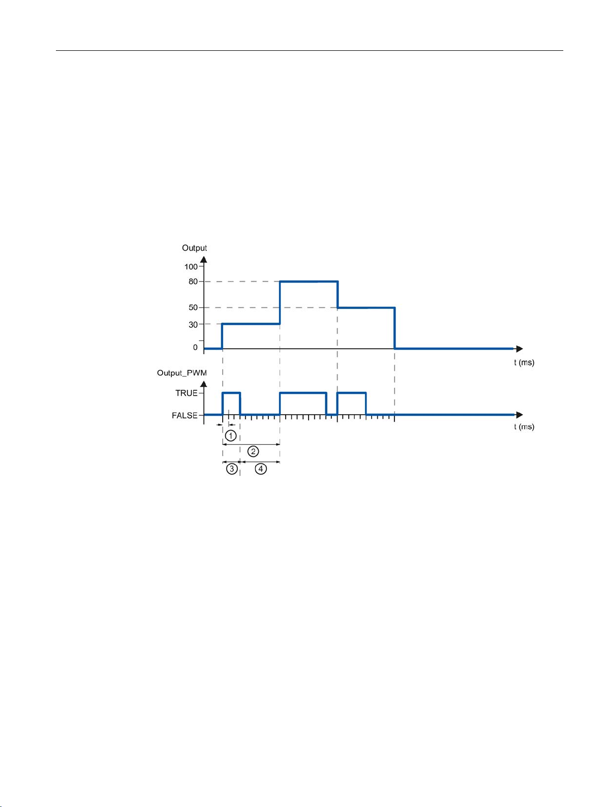
Using PID_Compact
PWM limits V2
①
PID_Compact sampling time
②
PID algorithm sampling time
③
Pulse duration
④
Break time
4.2 PID_Compact V2
The value at the output parameter Output is transformed into a pulse sequence that is output
at output parameter Output_PWM by means of a pulse width modulation. Output is
calculated in the PID algorithm sampling time, Output_PWM is output in the PID_Compact
sampling time.
The PID algorithm sampling time is determined during pretuning or fine tuning. If manually
setting the PID parameters, you will also need to configure the PID algorithm sampling time.
The PID_Compact sampling time is equivalent to the cycle time of the calling OB.
The pulse duration is proportional to the value at Output and is always an integer multiple of
the PID_Compact sampling time.
The "Minimum ON time" and the "Minimum OFF time" are rounded to an integer multiple of
the PID_Compact sampling time.
A pulse or a break is never shorter than the minimum ON or OFF time. The inaccuracies this
causes are added up and compensated in the next cycle.
PID control
Function Manual, 03/2017, A5E35300227-AC
79
Page 80
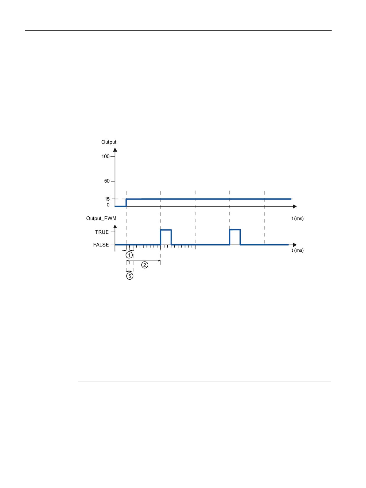
Using PID_Compact
Example
①
PID_Compact sampling time
②
PID algorithm sampling time
⑤
Minimum ON time
Note
The minimum ON and OFF times only affect the output parameter Output_PWM and are not
used for any pulse generators integrated in the CPU.
4.2 PID_Compact V2
PID_Compact sampling time = 100 ms
PID algorithm sampling time = 1000 ms
Minimum ON time = 200 ms
Output is a constant 15%. The smallest pulse that PID_Compact can output is 20%. In the
first cycle, no pulse is output. In the second cycle, the pulse not output in the first cycle is
added to the pulse of the second cycle.
In order to minimize operation frequency and conserve the actuator, extend the minimum ON
and OFF times.
If you are using "Output" or "Output_PER", you must configure the value 0.0 for the minimum
ON and OFF times.
PID control
80 Function Manual, 03/2017, A5E35300227-AC
Page 81

Using PID_Compact
Output value V2
Output value limits
Output
-100.0 to 100.0%
Output_PER
-100.0 to 100.0%
Output_PWM
0.0 to 100.0%
Reaction to error
NOTICE
Your system may be damaged.
automatic mode
4.2 PID_Compact V2
In the "Output value limits" configuration window, configure the absolute limits of your output
value in percent. Absolute output value limits are not violated in neither manual mode nor
automatic mode. If an output value outside the limits is specified in manual mode, the
effective value is limited in the CPU to the configured limits.
The output value limits must match the control logic.
The valid output value limit values depend on the Output used.
If you output "Current value while error pending " or "Substitute output value while error
pending" in the event of an error, PID_Compact remains in automatic mode. This may
cause a violation of the process value limits and damage your system.
It is essential to configure how your controlled system reacts in the event of an error to
protect your system from damage.
PID_Compact is preset so that the controller stays active in most cases in the event of an
error. If errors occur frequently in controller mode, this default reaction has a negative effect
on the control response. In this case, check the Errorbits parameter and eliminate the cause
of the error.
PID_Compact generates a programmable output value in response to an error:
● Zero (inactive)
PID_Compact outputs 0.0 as output value for all errors and switches to "Inactive" mode.
The controller is only reactivated by a falling edge at Reset or a rising edge at
ModeActivate.
● Current value while error is pending
If the following errors occur in
, PID_Compact returns to automatic mode
as soon as the errors are no longer pending.
PID control
Function Manual, 03/2017, A5E35300227-AC
If one or more of the following errors occur, PID_Compact stays in
automatic mode:
– 0001h: The "Input" parameter is outside the process value limits.
– 0800h: Sampling time error
– 40000h: Invalid value at Disturbance parameter.
81
Page 82

Using PID_Compact
automatic mode
manual mode
pretuning or fine tuning
See also
4.2 PID_Compact V2
If one or more of the following errors occur in
"Substitute output value with error monitoring" mode and outputs the last valid output
value:
– 0002h: Invalid value at Input_PER parameter.
– 0200h: Invalid value at Input parameter.
– 0400h: Calculation of output value failed.
– 1000h: Invalid value at Setpoint parameter.
If an error occurs in
the output value. If the manual value is invalid, the substitute output value is used. If the
manual value and substitute output value are invalid, the output value low limit is used.
If the following error occurs during a
active mode:
– 0020h: Pretuning is not permitted during fine tuning.
When any other error occurs, PID_Compact cancels the tuning and switches to the mode
from which tuning was started.
As soon as no errors are pending, PID_Compact returns to automatic mode.
● Substitute output value while error is pending
PID_Compact outputs the substitute output value.
If the following error occurs, PID_Compact stays in "Substitute output value with error
monitoring" mode and outputs the output value low limit:
, PID_Compact continues using the manual value as
, PID_Compact remains in
, PID_Compact switches to
– 20000h: Invalid value at SubstituteOutput tag.
For all other errors, PID_Compact reacts as described for "Current value while error is
pending".
Parameters State and Mode V2 (Page 265)
PID control
82 Function Manual, 03/2017, A5E35300227-AC
Page 83
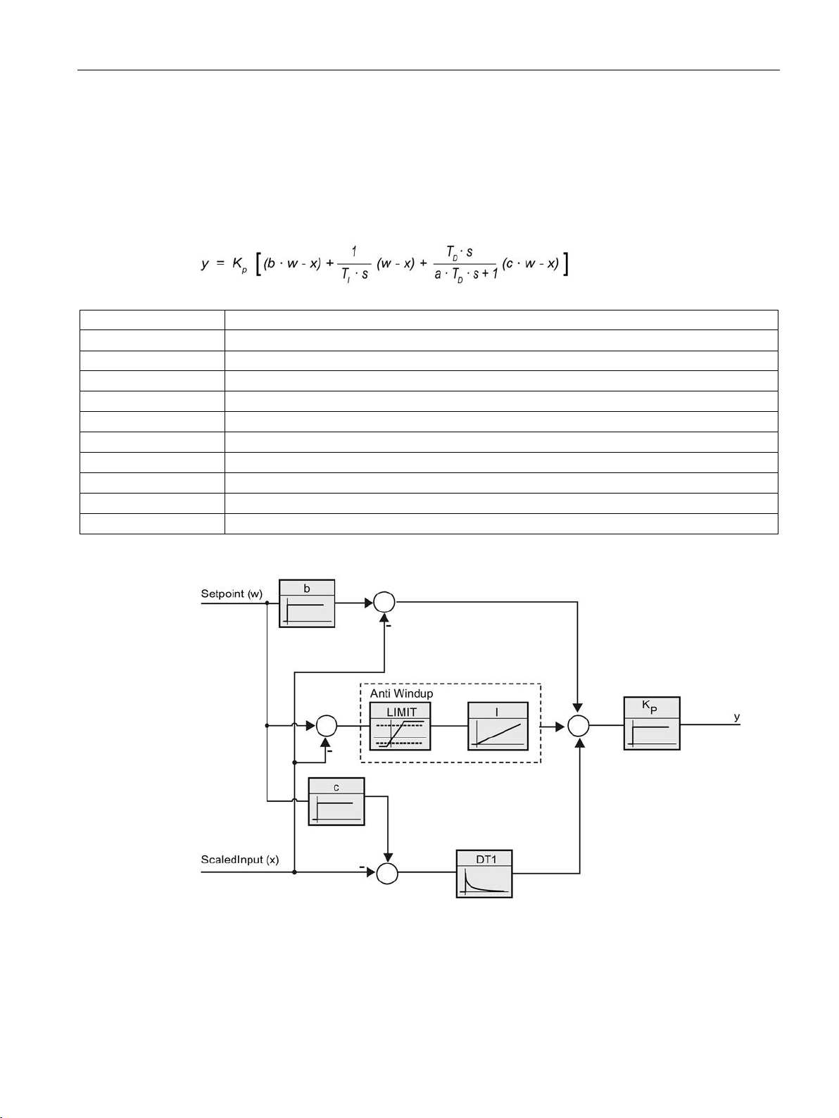
Using PID_Compact
PID parameters V2
Symbol
Description
Kp
Proportional gain
b
Proportional action weighting
w
Setpoint
x
Process value
TI
Integral action time
a
Derivative delay coefficient (derivative delay T1 = a × TD)
TD
Derivative action time
c
Derivative action weighting
4.2 PID_Compact V2
The PID parameters are displayed in the "PID Parameters" configuration window. The PID
parameters will be adapted to your controlled system during controller tuning. You do not
need to enter the PID parameters manually.
The PID algorithm operates according to the following equation:
y Output value of the PID algorithm
s Laplace operator
The diagram below illustrates the integration of the parameters into the PID algorithm:
All PID parameters are retentive. If you enter the PID parameters manually, you must
completely download PID_Compact.
Downloading technology objects to device (Page 44)
PID control
Function Manual, 03/2017, A5E35300227-AC
83
Page 84

Using PID_Compact
Proportional gain
Integral action time
Derivative action time
Derivative delay coefficient
one
Proportional action weighting
Derivative action weighting
4.2 PID_Compact V2
The value specifies the proportional gain of the controller. PID_Compact does not work with
a negative proportional gain. Control logic is inverted under Basic settings > Controller type.
The integral action time determines the time behavior of the integral action. The integral
action is deactivated with integral action time = 0.0.
The derivative action time determines the time behavior of the derivative action. Derivative
action is deactivated with derivative action time = 0.0.
The derivative delay coefficient delays the effect of the derivative action.
Derivative delay = derivative action time × derivative delay coefficient
● 0.0: Derivative action is effective for one cycle only and therefore almost not effective.
● 0.5: This value has proved useful in practice for controlled systems with
time constant.
● > 1.0: The greater the coefficient, the longer the effect of the derivative action is delayed.
The proportional action may weaken with changes to the setpoint.
Values from 0.0 to 1.0 are applicable.
● 1.0: Proportional action for setpoint change is fully effective
● 0.0: Proportional action for setpoint change is not effective
The proportional action is always fully effective when the process value is changed.
The derivative action may weaken with changes to the setpoint.
Values from 0.0 to 1.0 are applicable.
● 1.0: Derivative action is fully effective upon setpoint change
● 0.0: Derivative action is not effective upon setpoint change
dominant
The derivative action is always fully effective when the process value is changed.
PID control
84 Function Manual, 03/2017, A5E35300227-AC
Page 85

Using PID_Compact
PID algorithm sampling time
Rule for tuning
PID
PI
User-defined
4.2 PID_Compact V2
The controlled system needs a certain amount of time to respond to changes in the output
value. It is therefore not advisable to calculate the output value in every cycle. The sampling
time of the PID algorithm represents the time between two calculations of the output value. It
is calculated during tuning and rounded to a multiple of the cycle time. All other functions of
PID_Compact are executed at every call.
If you use Output_PWM, the accuracy of the output signal is determined by the ratio of the
PID algorithm sampling time to the cycle time of the OB. The PID algorithm sampling time
corresponds to the time period of the pulse width modulation. The cycle time should be at
least 10 times the PID algorithm sampling time.
Select whether PI or PID parameters are to be calculated in the "Controller structure" dropdown list.
●
Calculates PID parameters during pretuning and fine tuning.
●
Calculates PI parameters during pretuning and fine tuning.
●
The drop-down list displays "User-defined" if you have configured different controller
structures for pretuning and fine tuning via a user program.
PID control
Function Manual, 03/2017, A5E35300227-AC
85
Page 86

Using PID_Compact
4.2.2
Commissioning PID_Compact V2
4.2.2.1
Pretuning V2
Requirement
4.2 PID_Compact V2
The pretuning determines the process response to a jump change of the output value and
searches for the point of inflection. The PID parameters are calculated from the maximum
rate of rise and dead time of the controlled system. You obtain the best PID parameters
when you perform pretuning and fine tuning.
The more stable the process value is, the easier it is to calculate the PID parameters and the
more precise the result will be. Noise on the process value can be tolerated as long as the
rate of rise of the process value is significantly higher compared to the noise. This is most
likely the case in operating modes "Inactive" and "manual mode". The PID parameters are
backed up before being recalculated.
● The "PID_Compact" instruction is called in a cyclic interrupt OB.
● ManualEnable = FALSE
● Reset = FALSE
● PID_Compact is in one of the following modes: "Inactive", "Manual mode", or "Automatic
mode".
● The setpoint and the process value lie within the configured limits (see "Process value
monitoring" configuration).
● The difference between setpoint and process value is greater than 30% of the difference
between process value high limit and process value low limit.
● The distance between the setpoint and the process value is > 50% of the setpoint.
PID control
86 Function Manual, 03/2017, A5E35300227-AC
Page 87

Using PID_Compact
Procedure
Note
Click the "Stop" icon when the progress bar has reached 100% and it can be assumed
the controller tuning function is
object and, if necessary, restart controller tuning.
Result
See also
4.2 PID_Compact V2
To perform pretuning, follow these steps:
1. Double-click the "PID_Compact > Commissioning" entry in the project tree.
2. Select the entry "Pretuning" in the "Tuning mode" drop-down list.
3. Click the "Start" icon.
– An online connection will be established.
– Value recording is started.
– Pretuning is started.
– The "Status" field displays the current steps and any errors that may have occurred.
The progress bar indicates the progress of the current step.
blocked. Check the configuration of the technology
If pretuning was performed without an error message, the PID parameters have been tuned.
PID_Compact switches to automatic mode and uses the tuned parameters. The tuned PID
parameters will be retained during power OFF and a restart of the CPU.
If pretuning is not possible, PID_Compact responds with the configured reaction to errors.
Parameters State and Mode V2 (Page 265)
PID control
Function Manual, 03/2017, A5E35300227-AC
87
Page 88

Using PID_Compact
4.2.2.2
Fine tuning V2
Requirement
Process depends on initial situation
4.2 PID_Compact V2
Fine tuning generates a constant, limited oscillation of the process value. The PID
parameters are tuned for the operating point from the amplitude and frequency of this
oscillation. All PID parameters are recalculated from the results. PID parameters from fine
tuning usually have better master control and disturbance characteristics than PID
parameters from pretuning. You obtain the best PID parameters when you perform pretuning
and fine tuning.
PID_Compact automatically attempts to generate an oscillation greater than the noise of the
process value. Fine tuning is only minimally influenced by the stability of the process value.
The PID parameters are backed up before being recalculated.
● The PID_Compact instruction is called in a cyclic interrupt OB.
● ManualEnable = FALSE
● Reset = FALSE
● The setpoint and the process value lie within the configured limits.
● The control loop has stabilized at the operating point. The operating point is reached
when the process value corresponds to the setpoint.
● No disturbances are expected.
● PID_Compact is in one of the following operating modes: Inactive, automatic mode, or
manual mode.
Fine tuning can be started from the following operating modes: "Inactive", "automatic mode",
or "manual mode". Fine tuning proceeds as follows when started from:
● Automatic mode
Start fine tuning from automatic mode if you wish to improve the existing PID parameters
through tuning.
PID_Compact controls the system using the existing PID parameters until the control loop
has stabilized and the requirements for fine tuning have been met. Only then will fine
tuning start.
● Inactive or manual mode
If the requirements for pretuning are met, pretuning is started. The determined PID
parameters will be used for control until the control loop has stabilized and the
requirements for fine tuning have been met. Only then will fine tuning start. If pretuning is
not possible, PID_Compact responds with the configured reaction to errors.
An attempt is made to reach the setpoint with the minimum or maximum output value if
the process value for pretuning is already too near the setpoint. This can produce
increased overshoot.
PID control
88 Function Manual, 03/2017, A5E35300227-AC
Page 89

Using PID_Compact
Procedure
Note
Click the "Stop" icon in the "Tuning mode" group when the progress bar has reached
100% and it is to be assumed that tuning is blocked. Check the configuration of the
technology object and, if necessary,
Result
See also
4.2 PID_Compact V2
To perform fine tuning, follow these steps:
1. Select the entry "Fine tuning" in the "Tuning mode" drop-down list.
2. Click the "Start" icon.
– An online connection will be established.
– Value recording is started.
– The process of fine tuning is started.
– The "Status" field displays the current steps and any errors that may have occurred.
The progress bar indicates the progress of the current step.
restart controller tuning.
If no errors occurred during fine tuning, the PID parameters have been tuned. PID_Compact
switches to automatic mode and uses the tuned parameters. The tuned PID parameters will
be retained during power OFF and a restart of the CPU.
If errors occurred during "fine tuning", PID_Compact responds with the configured response
to errors.
Parameters State and Mode V2 (Page 265)
PID control
Function Manual, 03/2017, A5E35300227-AC
89
Page 90

Using PID_Compact
4.2.2.3
"Manual" mode V1
Requirement
Procedure
Result
See also
4.2 PID_Compact V2
The following section describes how you can use the "manual mode" operating mode in the
commissioning window of the "PID_Compact" technology object. Manual mode is also
possible when an error is pending.
● The "PID_Compact" instruction is called in a cyclic interrupt OB.
● An online connection to the CPU has been established and the CPU is in the "RUN"
mode.
Use "Manual mode" in the commissioning window if you want to test the controlled system
by specifying a manual value. To define a manual value, follow these steps:
1. Click the "Start" icon.
2. Select the "Manual mode" check box in the "Online status of controller" area.
PID_Compact operates in manual mode. The most recent current output value remains in
effect.
3. Enter the manual value in the "Output" field as a % value.
4. Click the
The manual value is written to the CPU and immediately goes into effect.
Clear the "Manual mode" check box if the output value is to be specified again by the PID
controller. The switchover to automatic mode is bumpless.
Parameters State and Mode V2 (Page 265)
icon.
PID control
90 Function Manual, 03/2017, A5E35300227-AC
Page 91

Using PID_Compact
4.2.3
Override control with PID_Compact V2
Override control
4.2 PID_Compact V2
In case of override control, two or more controllers share one actuator. Only one controller
has access to the actuator at any time and influences the process.
A logic operation decides which controller has access to the actuator. This decision is often
made based on a comparison of the output values of all controllers, for example, in case of a
maximum selection, the controller with the largest output value gets access to the actuator.
The selection based on the output value requires that all controllers operate in automatic
mode. The controllers that do not have an effect on the actuator are updated. This is
necessary to prevent windup effects and their negative impacts on the control response and
the switchover between the controllers.
PID_Compact supports override controls as of version 2.3 by offering a simple process for
updating the controllers that are not active: By using the tags OverwriteInitialOutputValue
and PIDCtrl.PIDInit, you can pre-assign the integral action of the controller in automatic
mode as though the PID algorithm had calculated Output = OverwriteInititalOutputValue for
the output value in the last cycle. To do this, OverwriteInitialOutputValue is interconnected
with the output value of the controller that currently has access to the actuator. By setting the
bit PIDCtrl.PIDInit, you trigger the pre-assignment of the integral action as well as the restart
of the controller cycle and the PWM period. The subsequent calculation of the output value
in the current cycle takes place based on the pre-assigned (and synchronized for all
controllers) integral action as well as the proportional action and integral action from the
current control deviation. The derivative action is not active during the call with
PIDCtrl.PIDInit = TRUE and therefore does not contribute to the output value.
This procedure ensures that the calculation of the current output value and thus the decision
on which controller is to have access to the actuator is only based on the current process
state and the PI parameters. Windup effects for controllers that are not active and thus
incorrect decisions of the switchover logic are prevented.
PID control
Function Manual, 03/2017, A5E35300227-AC
91
Page 92

Using PID_Compact
Requirements
Note
Constant adaptation of the output value limits
Instead of the active updating of the controllers without access to the actuator described
here, this is implemented alternatively by constant adaptation of the output value limits in
other controller systems.
This is not possibl
supported in automatic mode.
4.2 PID_Compact V2
● PIDCtrl.PIDInit is only effective if the integral action is activated (Retain.CtrlParams.Ti tag
> 0.0).
● You must assign PIDCtrl.PIDInit and OverwriteInitialOutputValue in your user program
yourself (see example below). PID_Compact does not automatically change these tags.
● PIDCtrl.PIDInit is only effective when PID_Compact is in automatic mode (parameter
State = 3)
● If possible, select the sampling time of the PID algorithm (Retain.CtrlParams.Cycle tag) in
such a way that it is identical for all controllers, and call all controllers in the same cyclic
interrupt OB. In this way, you ensure that the switchover does not take place within a
controller cycle or a PWM period.
e with PID_Compact, because a change of the output value limits is not
PID control
92 Function Manual, 03/2017, A5E35300227-AC
Page 93
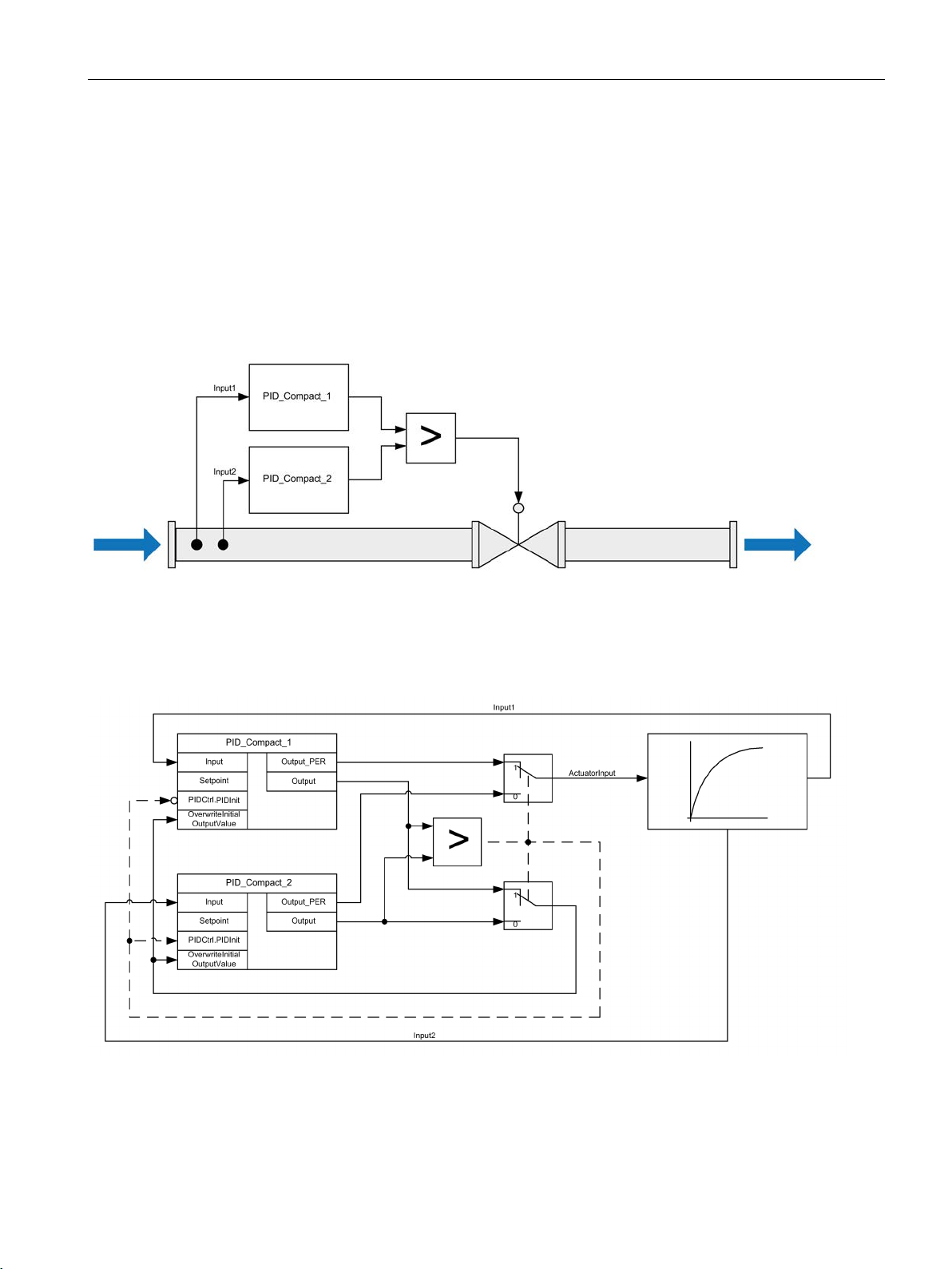
Using PID_Compact
Example: Control of a gas pipeline
4.2 PID_Compact V2
PID_Compact is used for control of a gas pipeline.
The main goal is to control the flow rate Input1. The controller PID_Compact_1 is used for
this purpose. In addition, the pressure Input2 (measured in flow direction in front of the valve)
is to be kept below the high limit with the limiting controller PID_Compact_2.
Flow rate and pressure are controlled by a single solenoid valve. The output value of the
controller corresponds to the valve opening: The valve is opened when the output value
increases. This means the flow rate increases (normal control logic) while the pressure drops
(inverted control logic).
The valve is controlled with the output value of PID_Compact in I/O format (parameter
Output_PER) by writing the program tag ActuatorInput.
The setpoint for the flow rate is specified at the parameter PID_Compact_1.Setpoint.
The pressure high limit is specified as setpoint at the parameter PID_Compact_2.Setpoint.
PID control
Function Manual, 03/2017, A5E35300227-AC
93
Page 94

Using PID_Compact
Note
Activate inversion of the control logic
Because a decrease of the actual value (pressure) is to be achieved with the pressure
regulator PID_Compact_2 when the output value increases (valve opening), the inversion of
the control logic must be activated: PID_Compact_2.Config.InvertControl = TRUE.
4.2 PID_Compact V2
Both controllers must share one valve as shared actuator. The logic that decides which
controller gets access to the actuator is implemented by a maximum selection of the output
value (in Real format, parameter Output) in this case. Because the output value corresponds
to the opening of the valve, the controller that requires the larger valve opening gets the
control.
In normal operation of the plant, the actual value of the flow rate corresponds to the setpoint.
The flow controller PID_Compact_1 has settled on a stationary output value
PID_Compact_1.Output. The actual value of the pressure in normal operation is significantly
below the high limit that is specified as setpoint for PID_Compact_2. The pressure regulator
therefore wants to close the valve even further to increase the pressure, which means it will
calculate an output value PID_Compact_2.Output that is smaller than the output value of the
flow controller PID_Compact_1.Output. The maximum selection of the switchover logic
therefore gives the flow controller PID_Compact_1 continued access to the actuator. In
addition, it is ensured that PID_Compact_2 is updated by means of the assignments
PID_Compact_2.OverwriteInitialOutputValue = PID_Compact_1.Output and
PID_Compact_2.PIDCtrl.PIDInit = TRUE.
If the pressure now approaches the high limit or exceeds it, for example due to a fault, the
pressure regulator PID_Compact_2 calculates a higher output value to open the valve even
further and thus reduce the pressure. If PID_Compact_2.Output is greater than
PID_Compact_1.Output, the pressure regulator PID_Compact_2 receives access to the
actuator through the maximum selection and opens it. It is ensured that PID_Compact_1 is
updated by means of the assignments PID_Compact_1.OverwriteInitialOutputValue =
PID_Compact_2.Output and PID_Compact_1.PIDCtrl.PIDInit = TRUE.
The pressure is reduced while the flow rate increases and can no longer be kept at the
setpoint.
Once the fault has been remedied, the pressure will continue to drop and the opening of the
valve is reduced by the pressure regulator. If the flow controller calculates a larger opening
as output value, the plant returns to normal operation so that the flow controller
PID_Compact_1 once again has access to the actuator.
PID control
94 Function Manual, 03/2017, A5E35300227-AC
Page 95

Using PID_Compact
"PID Compact 1"(Input := "Input1");
"PID Compact 2"(Input := "Input2");
IF "PID Compact 1".Output >= "PID Compact 2".Output THEN
"ActuatorInput" := "PID_Compact_1".Output_PER;
"PID_Compact_1".PIDCtrl.PIDInit := FALSE;
"PID_Compact_2".PIDCtrl.PIDInit := TRUE;
"PID_Compact_2".OverwriteInitialOutputValue := "PID_Compact_1".Output;
ELSE
"ActuatorInput" := "PID_Compact_2".Output_PER;
"PID_Compact_1".PIDCtrl.PIDInit := TRUE;
"PID_Compact_2".PIDCtrl.PIDInit := FALSE;
"PID_Compact_1".OverwriteInitialOutputValue := "PID_Compact_2".Output;
END IF;
4.2.4
Simulating PID_Compact V2 with PLCSIM
Note
Simulation with PLCSIM
The simulation of PID_Compact V2.x with PLCSIM for CPU S7
PID_Compact V2.x can only be simulated for CPU S7
For the simulation with PLCSIM, the time
identical to that of a "real" PLC. The actual cycle clock of a cyclic interrupt OB can have
larger fluctuations with a simulated PLC than with "real" PLCs.
In the standard configuration, PID_Compact determines the time between calls automatically
and monitors them for fluctuations.
For the simulation of PID_Compact with PLCSIM, for example, a sampling time error
(ErrorBits = DW#16#00000800) can therefore be detected.
This results in ongoing tuning being aborted.
The response in automatic mode depends on the value of the ActivateRecoverMode tag.
To prevent this from happening, you should configure PID_Compact for simulation with
PLCSIM as follows:
•
•
•
4.2 PID_Compact V2
This example can be implemented with the following SCL program code:
-1500 with PLCSIM.
behavior of the simulated PLC is not exactly
CycleTime.EnEstimation = FALSE
CycleTime.EnMonitoring = FALSE
CycleTime.Value: Assign the cycle clock of the calling cyclic interrupt OB in seconds to
this tag.
-1200 is not supported.
PID control
Function Manual, 03/2017, A5E35300227-AC
95
Page 96

Using PID_Compact
4.3
PID_Compact V1
4.3.1
Configuring PID_Compact V1
4.3.1.1
Basic settings V1
Introduction V1
Setpoint, process value and output value
4.3 PID_Compact V1
Configure the following properties of the "PID_Compact" technology object under "Basic
settings" in the Inspector window or in the configuration window:
● Physical quantity
● Control logic
● Start-up behavior after reset
● Setpoint (only in the Inspector window)
● Process value (only in the Inspector window)
● Output value (only in the Inspector window)
You can only configure the setpoint, process value and output value in the Inspector window
of the programming editor. Select the source for each value:
● Instance DB
The value saved in the instance DB is used.
Value must be updated in the instance DB by the user program.
There should be no value at the instruction.
Change via HMI possible.
● Instruction
The value connected to the instruction is used.
The value is written to the instance DB each time the instruction is called.
No change via HMI possible.
PID control
96 Function Manual, 03/2017, A5E35300227-AC
Page 97

Using PID_Compact
Control mode V1
Physical quantity
Control logic
Start-up behavior after reset
Setpoint V1
Procedure
4.3 PID_Compact V1
Select the unit of measurement and physical quantity for the setpoint and process value in
the "Controller type" group. The setpoint and process value will be displayed in this unit.
An increase of the output value is generally intended to cause an increase in the process
value. This is referred to as a normal control logic.
PID_Compact does not work with negative proportional gain. Select the check box "Invert
control logic" to reduce the process value with a higher output value.
Examples
● Opening the drain valve will reduce the level of a container's contents.
● Increasing cooling will reduce the temperature.
To change straight to the last active mode after restarting the CPU, select the "Enable last
mode after CPU restart" check box.
PID_Compact will remain in "Inactive" mode if the check box is cleared.
Proceed as follows to define a fixed setpoint:
1. Select "Instance DB".
2. Enter a setpoint, e.g. 80° C.
3. Delete any entry in the instruction.
Proceed as follows to define a variable setpoint:
1. Select "Instruction".
2. Enter the name of the REAL variable in which the setpoint is saved.
Program-controlled assignment of various values to the REAL variable is possible, for
example for the time controlled change of the setpoint.
PID control
Function Manual, 03/2017, A5E35300227-AC
97
Page 98

Using PID_Compact
Process value V1
Procedure
Output value V1
4.3 PID_Compact V1
PID_Compact will scale the value of the analog input to the physical quantity if you use the
analog input value directly.
You will need to write a program for processing if you wish first to process the analog input
value. The process value is, for example, not directly proportional to the value at the analog
input. The processed process value must be in floating point format.
Proceed as follows to use the analog input value without processing:
1. Select the entry "Input_PER" in the drop-down list "Input".
2. Select "Instruction" as source.
3. Enter the address of the analog input.
Proceed as follows to use the processed process value in floating point format:
1. Select the entry "Input" in the drop-down list "Input".
2. Select "Instruction" as source.
3. Enter the name of the variable in which the processed process value is saved.
PID_Compact offers three output values. Your actuator will determine which output value
you use.
● Output_PER
The actuator is triggered via an analog output and controlled with a continuous signal,
e.g. 0...10V, 4...20mA.
● Output
The output value needs to be processed by the user program, for example because of
nonlinear actuator response.
● Output_PWM
The actuator is controlled via a digital output. Pulse width modulation creates minimum
ON and minimum OFF times.
PID control
98 Function Manual, 03/2017, A5E35300227-AC
Page 99

Using PID_Compact
Procedure
4.3 PID_Compact V1
Proceed as follows to use the analog output value:
1. Select the entry "Output_PER (analog)" in the drop-down list "Output".
2. Select "Instruction".
3. Enter the address of the analog output.
Proceed as follows to process the output value using the user program:
1. Select the entry "Output" in the drop-down list "Output".
2. Select "Instance DB".
The calculated output value is saved in the instance data block.
3. For the preparation of the output value, use the output parameter Output.
4. Transfer the processed output value to the actuator via a digital or analog CPU output.
Proceed as follows to use the digital output value:
1. Select the entry "Output_PWM" in the drop-down list "Output".
2. Select "Instruction".
3. Enter the address of the digital output.
PID control
Function Manual, 03/2017, A5E35300227-AC
99
Page 100
Using PID_Compact
4.3.1.2
Process value settings V1
Scaling the process value
Monitoring process value
WARNING
See also
4.3 PID_Compact V1
Configure the scaling of your process value and specify the process value absolute limits In
the "Process value settings" configuration window.
If you have configured the use of Input_PER in the basic settings, you will need to convert
the value of the analog input into the physical quantity of the process value. The current
configuration will be displayed in the Input_PER display.
Input_PER will be scaled using a low and high value pair if the process value is directly
proportional to the value of the analog input.
1. Enter the low pair of values in the "Scaled low process value" and "Low" input fields.
2. Enter the high pair of values in the "Scaled high process value" and "High" input boxes.
Default settings for the value pairs are saved in the hardware configuration. Proceed as
follows to use the value pairs from the hardware configuration:
1. Select the instruction PID_Compact in the programming editor.
2. Connect Input_PER with an analog input in the basic settings.
3. Click on the "Automatic setting" button in the process value settings.
The existing values will be overwritten with the values from the hardware configuration.
Specify the absolute high and low limit of the process value. As soon as these limits are
violated during operation, the controller switches off and the output value is set to 0%. You
must enter reasonable limits for your controlled system. Reasonable limits are important
during optimization to obtain optimal PID parameters.
The default for the "High limit process value" is 120 %. At the I/O input, the process value
can be a maximum of 18% higher than the standard range (overrange). An error is no longer
reported for a violation of the "High limit process value". Only a wire-break and a short-circuit
are recognized and the PID_Compact switches to "Inactive" mode.
If you set very high process value limits (for example -3.4*1038...+3.4*1038), process value
monitoring will be disabled. Your system may then be damaged if an error occurs.
Process value monitoring V1 (Page 101)
PWM limits V1 (Page 102)
Output value limits V1 (Page 104)
PID parameters V1 (Page 104)
PID control
100 Function Manual, 03/2017, A5E35300227-AC
 Loading...