

Page 1

SIMATIC RTLS
Localization systems
SIMATIC RTLS4420G
Device manual
06/2019
C79000-G8976-C516-02
Page 2
Legal information
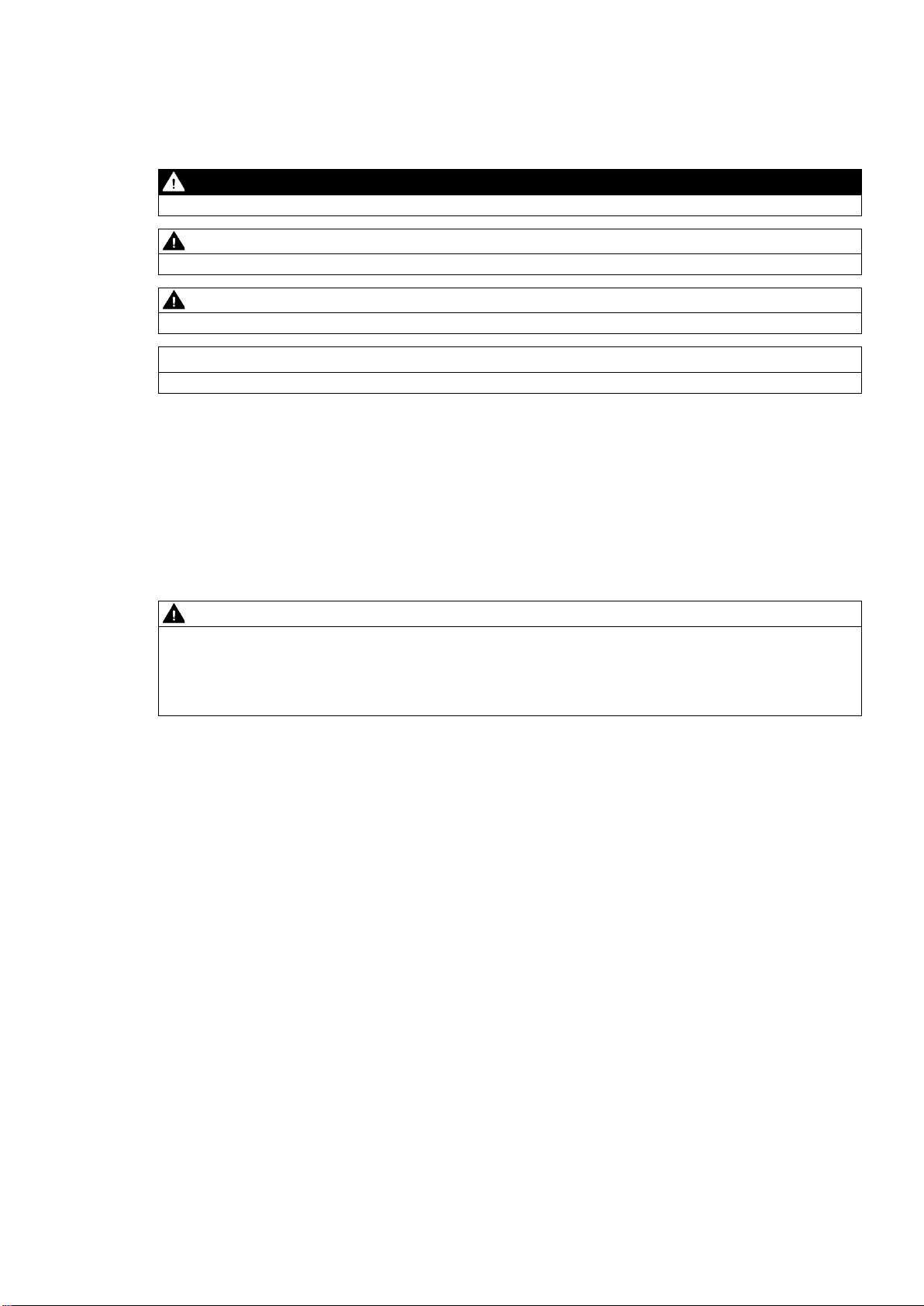
DANGER
indicates that death or severe personal injury will result if proper precautions are not taken.
WARNING
indicates that death or severe personal injury may result if proper precautions are not taken.
CAUTION
indicates that minor personal injury can result if proper precautions are not taken.
NOTICE
indicates that property damage can result if proper precautions are not taken.
WARNING
Siemens products may only be used for the applications described in the catalog and in the relevant technical
ambient conditions must be complied with. The information in the relevant documentation must be observed.
Warning notice system
This manual contains notices you have to observe in order to ensure your personal safety, as well as to prevent
damage to property. The notices referring to your personal safety are highlighted in the manual by a safety alert
symbol, notices referring only to property damage have no safety alert symbol. These notices shown below are
graded according to the degree of danger.
If more than one degree of danger is present, the warning notice representing the highest degree of danger will
be used. A notice warning of injury to persons with a safety alert symbol may also include a warning relating to
property damage.
Qualified Personnel
The product/system described in this documentation may be operated only by personnel qualified for the specific
task in accordance with the relevant documentation, in particular its warning notices and safety instructions.
Qualified personnel are those who, based on their training and experience, are capable of identifying risks and
avoiding potential hazards when working with these products/systems.
Proper use of Siemens products
Note the following:
documentation. If products and components from other manufacturers are used, these must be recommended
or approved by Siemens. Proper transport, storage, installation, assembly, commissioning, operation and
maintenance are required to ensure that the products operate safely and without any problems. The permissible
Trademarks
All names identified by ® are registered trademarks of Siemens AG. The remaining trademarks in this publication
may be trademarks whose use by third parties for their own purposes could violate the rights of the owner.
Disclaimer of Liability
We have reviewed the contents of this publication to ensure consistency with the hardware and software
described. Since variance cannot be precluded entirely, we cannot guarantee full consistency. However, the
information in this publication is reviewed regularly and any necessary corrections are included in subsequent
editions.
SIMATIC RTLS4420G
2 Device manual, 06/2019, C79000-G8976-C516-02
Page 3

Table of contents
English
1 Overview ................................................................................................................................................... 5
1.1 General ........................................................................................................................................................ 5
1.2 Scope of delivery ......................................................................................................................................... 5
2 Layout and connections ............................................................................................................................. 5
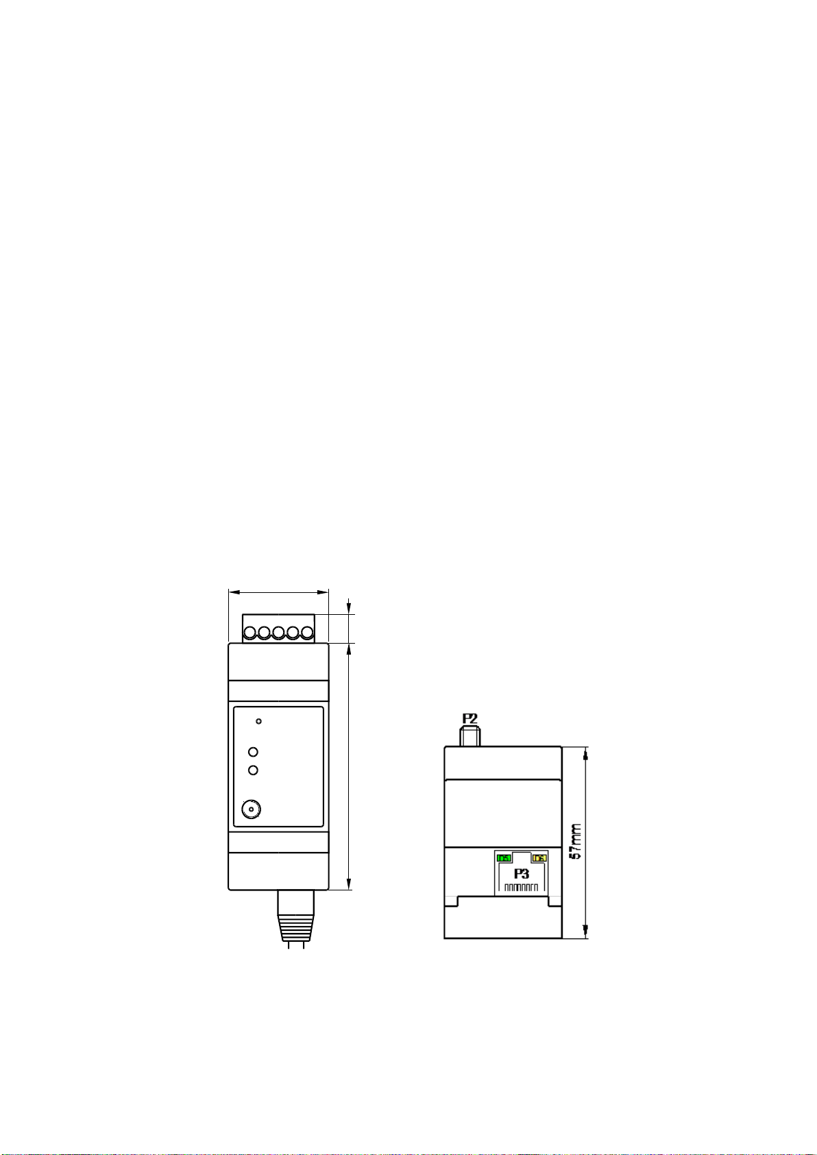
2.1 Dimensions .................................................................................................................................................. 5
2.2 Connections and displays ........................................................................................................................... 6
2.2.1 Possible states of the LEDs ........................................................................................................................ 6
2.3 Pin allocation ............................................................................................................................................... 7
2.3.1 P1 - Power .................................................................................................................................................. 7
2.3.2 P2 - Antenna – RP-SMA connector ............................................................................................................ 7
2.3.3 P2 - RJ45 Ethernet ..................................................................................................................................... 8
3 Installation, initial start-up, safety ............................................................................................................... 9
3.1 General information ..................................................................................................................................... 9
3.2 Installation ................................................................................................................................................... 9
3.3 Connecting the cables ................................................................................................................................. 9
3.3.1 Power supply .............................................................................................................................................. 9
3.3.2 Ethernet .................................................................................................................................................... 10
3.4 Connecting the antenna ............................................................................................................................ 10
4 Troubleshooting ....................................................................................................................................... 10
4.1 General errors ........................................................................................................................................... 10
5 Technical data ......................................................................................................................................... 11
5.1 Connectors and power supply ................................................................................................................... 11
5.2 In- and outputs........................................................................................................................................... 11
5.3 Ethernet ..................................................................................................................................................... 11
5.4 Radio ......................................................................................................................................................... 11
5.5 Environment .............................................................................................................................................. 12
SIMATIC RTLS4420G
Device manual, 06/2019, C79000-G8976-C516-02
3
Page 4

6 Approvals ................................................................................................................................................ 13
6.1 EU declaration of conformity ..................................................................................................................... 13
6.2 RoHS ......................................................................................................................................................... 13
6.3 RED ........................................................................................................................................................... 14
6.3.1 Protection of health and safety ................................................................................................................. 14
6.4 Recycling and disposal .............................................................................................................................. 15
SIMATIC RTLS4420G
4 Device manual, 06/2019, C79000-G8976-C516-02
Page 5
P1
86mm
35mm
10mm
P3
P2
D1
D2
S1
9
7 86 10
1 Overview
1.1 General
The SIMATIC RTLS4420G represents, like the SIMATIC RTLS 4420A, a basing point with a
fixed position for the localization within the SIMATIC Locating Manager. The gateway can be
connected to the local IT-infrastructure via Ethernet. Through this connection the nodes
(anchors and gateways) will exchange the localization data gathered as well as customer
specific data between the localization network and the localization server. It is suggested to
deploy several gateways for larger localization networks in order to raise the number of
locatable transponders and to enhance the availability of the position information.
1.2 Scope of delivery
• 1 SIMATIC RTLS4420G (article number 6GT2701-2CB02)
• 1 Power connector (5-pole)
2 Layout and connections
2.1 Dimensions
SIMATIC RTLS4420G
Device manual, 06/2019, C79000-G8976-C516-02
5
Page 6

Connection
Description
Display
Description
D1 - Radio LED
D2 - Run LED
Description
2.2 Connections and displays
P1 - Power 5-pin plug-in screw terminal connector
P2 - Antenna RP-SMA antenna screw connector
P3 - Ethernet RJ45 Ethernet (10/100 Mbit)
S1 - Button Reset button for resetting to factory settings
D1 - Radio LED (yellow)
D2 - Run LED (green) LED signaling the device’s operating status
LED signaling the activity of the Locating Manager (sending and receiving
radio signals)
2.2.1 Possible states of the LEDs
Off Device is inactive
Flashes regularly Flashes
regularly
Flashes - Signals radio activity (sending and receiving radio signals)
- On Device is operating
Signals an error
SIMATIC RTLS4420G
6 Device manual, 06/2019, C79000-G8976-C516-02
Page 7
Pin
Description
Pin
Description
P1
6 7 8 9
10
Power supply
Digi t al output
Gr o u n d
9
6
8
GND
9
6
7
GND
2.3 Pin allocation
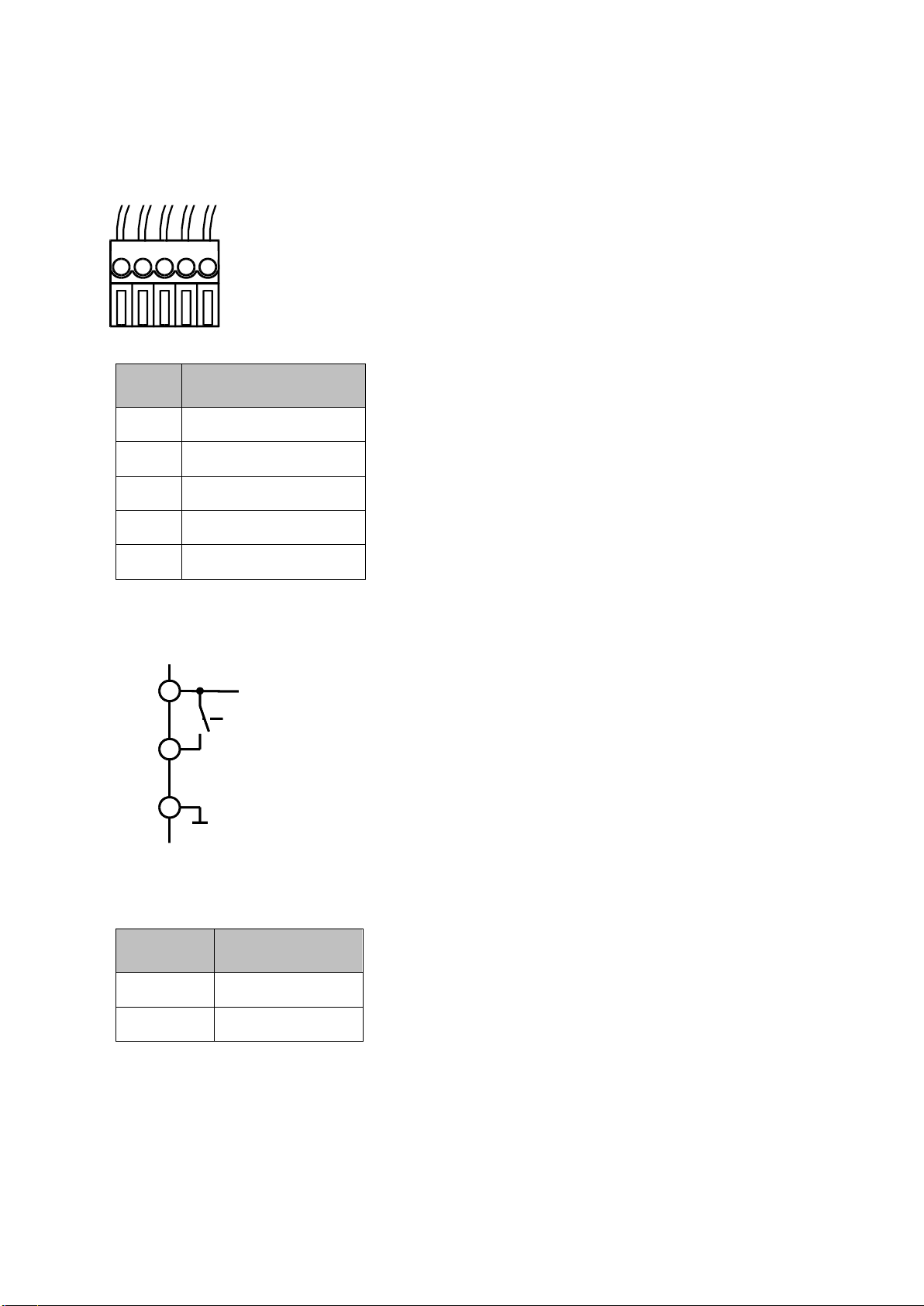
2.3.1 P1 - Power
6 Digital output
7 GND
8 GND
5-pin plug-in screw terminal connector
0.13 mm² to 3.3 mm²
9 Voltage supply
10 Ethernet shielding
Digital output - Pin 6
A high-side-switch toggles the voltage supply to the digital output (pin 6).
Output voltage: 0 (switched off) or input voltage (switched on)
Maximum output current: 100 mA
2.3.2 P2 - Antenna – RP-SMA connector
SIMATIC RTLS4420G
Device manual, 06/2019, C79000-G8976-C516-02
1 Antenna
Shield GND, Shield
7
Page 8
Pin
Description
D5
Description
D6
Description
2.3.3 P2 - RJ45 Ethernet
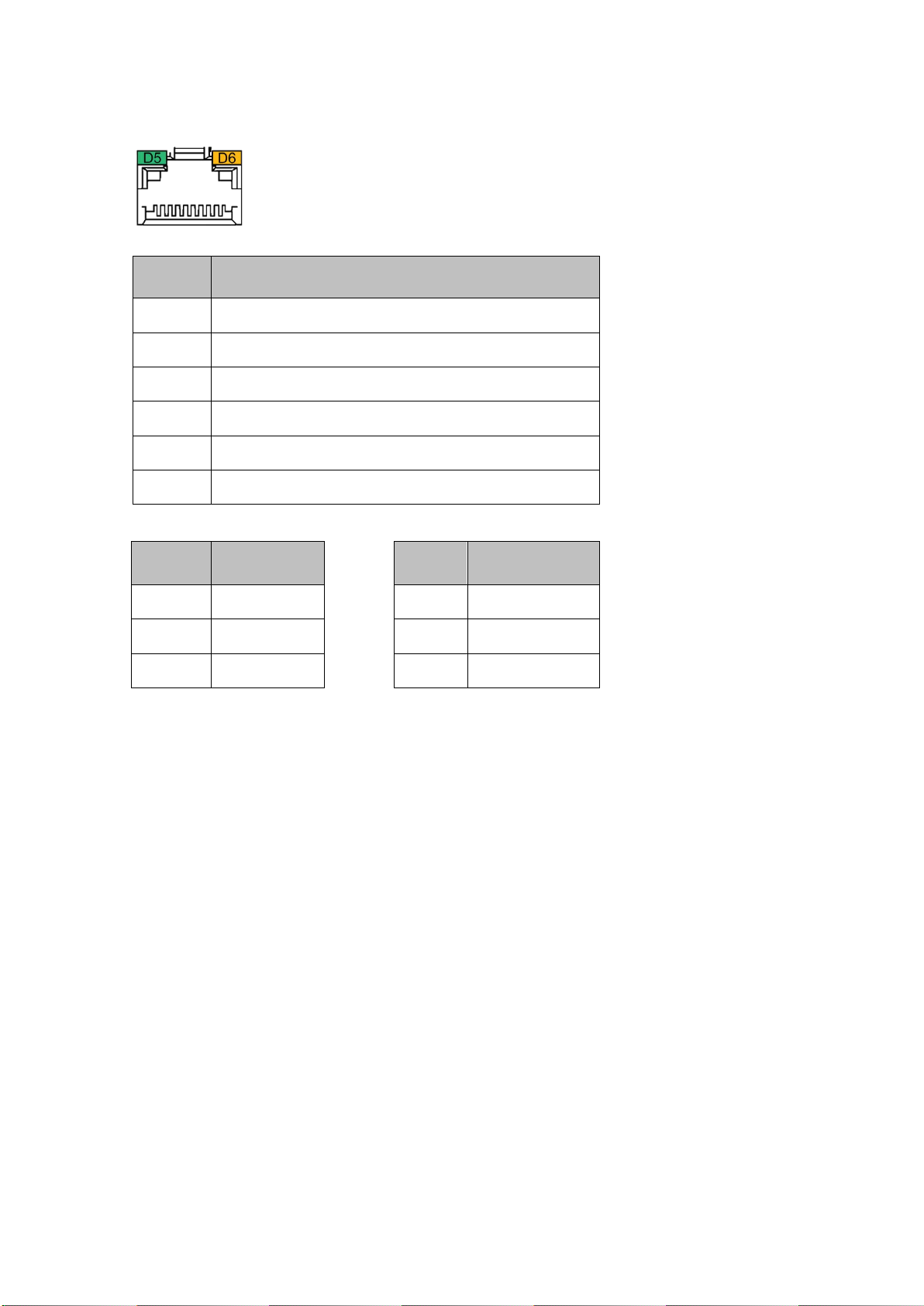
1 Differential Ethernet transmit Data +
2 Differential Ethernet transmit Data -
3 Differential Ethernet receive Data +
6 Differential Ethernet receive Data -
4, 5, 7, 8 not connected
Shield Ground
Off No Link Off no activity
Yellow 10 MBit Yellow half duplex activity
Green 100 MBit Green full duplex activity
SIMATIC RTLS4420G
8 Device manual, 06/2019, C79000-G8976-C516-02
Page 9

3 Installation, initial start-up, safety
3.1 General information
• The devices can only be used in combination with the Locating Manager.
• Buildup, installation as well as the use of the tools and clients of the localization system are
described in the corresponding guides and manuals.
3.2 Installation
• Carefully read ALL items listed in section 3 (Installation, initial start-up, safety) before
installing the devices in order to safeguard correct installation and operation.
• The device is destined for fitting on a DIN top-hat rail fixed into a housing or onto walls or
ceilings.
• The installation has to be carried out by appropriately qualified and trained personnel and
according to the installation guide.
• Follow the references concerning the surrounding conditions when installing and operating
the devices.
• The device has to be protected against moisture.
• The ambient temperature must not exceed 70 °C. Avoid installing devices at locations
exposed to direct sunlight.
• The installation of the devices has to be carried out according to the applicable provisions
for the
installation of electrical systems and utilities.
3.3 Connecting the cables
• Make sure that any wiring has been carried out correctly before the start-up of the device.
3.3.1 Power supply
• When connecting the power supply to the power connector, all LEDs flash for an instant.
The power LED is on, if power is supplied (cf. states of the LEDs 2.2.1).
• Check whether the nominal voltage of the power supply is in accordance with the values
stated in section “Technical data” (cf. 5).
SIMATIC RTLS4420G
Device manual, 06/2019, C79000-G8976-C516-02
9
Page 10

Fault detection
Cause of error
Troubleshooting
3.3.2 Ethernet
• Mind the relevant general conditions and their legal basis when installing and connecting
the Ethernet line.
• Connect the Ethernet cable to the appropriate socket. Assemble the Ethernet cable into the
RJ45 jack beforehand.
3.4 Connecting the antenna
• The antenna has to be connected to the RP-SMA screw connector (P2).
• The device must not be operated without antenna. The device has to be switched off or
voltage-free before replacing the antenna.
• The antennas of all wireless devices should be aligned similarly.
• The device should be mounted as aloft as possible and have a clear line of sight to the
possible locations of transponders.
4 Troubleshooting
4.1 General errors
Wireless module does not react,
all LEDs are off
Flashing Run-LED during
operation
Module is not connected not
switched on.
Error within the module Reset the module by switching it off
Check module’s power supply,
switch on module.
and on again. Contact Siemens
Support in case the error occurs
repeatedly.
SIMATIC RTLS4420G
10 Device manual, 06/2019, C79000-G8976-C516-02
Page 11
Connectors and power supply
In- and outputs
Ethernet
Radio
5 Technical data
5.1 Connectors and power supply
Voltage 8 … 30 V DC
Power consumption Max. 1.6 W
Power connector (P1) 5-pin plug-in screw terminal connector, 0.13 mm² … 3.3 mm²
Antenna connector RP SMA screw connector
Ethernet RJ45 Ethernet (10/100 MBit)
5.2 In- and outputs
Output High-side-switch > Connect to input voltage
Output current Max. 100 mA, short-circuit proof
Output voltage 0 V or supply voltage
5.3 Ethernet
Interfaces 10/100 MBit
Duplex mode Half and full duplex
5.4 Radio
Wireless technology IEEE 802.15.4a nanoLOC - Chirp Spread Spectrum (CSS)
Data rates 1 MBit/s
Operating frequency 2.45 GHz ISM-Band
Chirp bandwidth 80 MHz
Output power max. 100 mW, adjustable
Range at 1 Mbit Indoor: max. 90 m
SIMATIC RTLS4420G
Device manual, 06/2019, C79000-G8976-C516-02
Outdoor: max. 1000 m (typically 500 m)
11
Page 12

Environment and dimensions
5.5 Environment
Case Plastic housing
IP-protection IP 40
Dimension 35 x 86 x 58 mm
Weight 80 g
Mounting Standard rail DIN 60 715 TH35
Temperature range -40 … +70 °C
SIMATIC RTLS4420G
12 Device manual, 06/2019, C79000-G8976-C516-02
Page 13

6 Approvals
6.1 EU declaration of conformity
You can find the current EU declaration of conformity for these products on the Internet pages
under Siemens Industry Online Support
(https://support.industry.siemens.com/cs/ww/en/ps/14970/cert
The products described in this document meet the requirements of the following EC directives:
• RoHS directive 2011/65/EU
Directive of the European Parliament and of the Council of 8 June 2011 on the
restriction of the use of certain hazardous substances in electrical and electronic
equipment, official journal of the EU L174, 01/07/2011, pages 88-110
• Radio equipment directive 2014/53/EU (RED, Radio Equipment Directive)
Directive of the European Parliament and of the Council of 16 April 2014 on the
harmonization of the laws of the Member States relating to the making available on the
market of radio equipment; official journal of the EU L153, 22/05/2014, pages 62-106
6.2 RoHS
RoHS directive (restriction of the use of certain hazardous substances)
The products described in these operating instructions meet the requirements of the EU
directive 2011/65/EU for the restriction of the use of certain hazardous substances in electrical
and electronic equipment.
)
Applied standard:
• EN 50581
Technical documentation for the assessment of electrical and electronic products with
respect to the restriction of hazardous substances
SIMATIC RTLS4420G
Device manual, 06/2019, C79000-G8976-C516-02
13
Page 14

6.3 RED
6.3.1 Protection of health and safety
The products described in this document meet the requirements of the applied standards:
Article 3 (1) a) protection of health and safety
• EN 62368-1
Information technology equipment - Safety - Part 1: General requirements
• EN 62311
Assessment of electronic and electrical equipment related to human exposure restrictions for
electromagnetic fields (0 Hz – 300 GHz)
The products described in these operating instructions meet the requirements of EU directive
2014/30/EU "Electromagnetic Compatibility" according to the designated standards for the
following areas of application.
Art. 3 (1) b) EMC:
• ETSI EN 301 489-1
Electromagnetic compatibility and radio spectrum matters (ERM) - Electromagnetic
compatibility for radio equipment and services - Part 1: Common technical requirements
• ETSI EN 301 489-17
Electromagnetic compatibility and radio spectrum matters (ERM) - Electromagnetic
compatibility for radio equipment and services - Part 17:
Specific conditions for Broadband Data Transmission Systems
• EN 55011
Industrial, scientific and medical equipment - Radio-frequency disturbance characteristics -
Limits and methods of measurement
• EN 55032 Class A, Class B
Electromagnetic compatibility of multimedia equipment - Emission requirements
• EN 55035
Electromagnetic compatibility of multimedia equipment - Immunity requirements
• EN 61000-6-1
Electromagnetic compatibility (EMC) - Part 6-1: Generic standards - Immunity standard for
residential, commercial and light-industrial environments
• EN 61000-6-2
Electromagnetic compatibility (EMC) - Part 6-2: Generic standards - Immunity standard for
industrial environments
• EN 61000-6-3
Electromagnetic compatibility (EMC) - Part 6-3: Generic standards - Emission standard for
residential, commercial and light-industrial environments
SIMATIC RTLS4420G
14 Device manual, 06/2019, C79000-G8976-C516-02
Page 15

Note
The specified approvals apply only when the corresponding mark is printed on the device.
• EN 61000-6-4
Electromagnetic compatibility (EMC) - Part 6-4: Generic standards - Emission standard for
industrial environments
Art. 3 (2) Efficient use of the radio spectrum
• ETSI EN 300 328
Wideband transmission systems; Data transmission equipment operating in the 2,4 GHz ISM
band and using wide band modulation techniques; Harmonised Standard covering the
essential requirements of article 3.2 of Directive 2014/53/EU
6.4 Recycling and disposal
The products are low in harmful substances, can be recycled and meet the requirements of the
Directive 2012/19/EU for disposal of waste electrical and electronic equipment (WEEE).
Do not dispose of the products at public disposal sites.
For environmentally compliant recycling and disposal of your electronic waste, please contact a
company certified for the disposal of electronic waste or your Siemens representative.
Note the different national regulations.
SIMATIC RTLS4420G
Device manual, 06/2019, C79000-G8976-C516-02
15
 Loading...