

Page 1

Contents, Preface
SIMATIC
Rack PC IL 40
Intel Pentium 4 Platform
Getting Started
First Steps in Commissioning
Important Information
Commissioning
Operating
Appendix
Guidelines for ESD
1
2
3
A
Edition 03/2003
A5E00171493-02
Page 2
Safety Guidelines
This Getting Started contains notices intended to ensure personal safety, as well as to protect the products
and connected equipment against damage. These notices are highlighted by the symbols shown below and
graded according to severity by the following texts:
!
!
!
Danger
indicates that death, severe personal injury or substantial property damage will result if proper
precautions are not taken.
Warning
indicates that death, severe personal injury or substantial property damage can result if proper
precautions are not taken.
Caution
indicates that minor personal injury can result if proper precautions are not taken.
Caution
indicates that property damage can result if proper precautions are not taken.
Notice
draws your attention to particularly important information on the product, handli ng the product , or t o a
particular part of the documentation.
Qualified Personnel
Repair, maintenance and servicing of device only to be carried out by qualified personnel. Qualified persons
are defined as persons who are authorized to commission, to ground and to tag circuits, equipment, and
systems in accordance with established safety practices and standards.
Correct Usage
Note the following:
Warning
!
Trademarks
Copyright © Siemens AG 2003 All rights reserved
The reproduction, transmission or use of this document or its
contents is not permitted without express written authority.
Offenders will be liable for damages. All rights, including rights
created by patent grant or registr ation of a utility model or design,
are reserved.
Siemens AG
Bereich Automation and Drives
Geschaeftsgebiet Systems Engineering
Postfach 2355, D- 90766 Fuerth
Siemens Aktiengesellschaft A5E00171493-02
This device and its components may only be used for the applications described in the catalog or the
technical description, and only in connection with devices or components from ot her manufact urers
which have been approved or recommended by Siemens.
This product can only function correctly and safely if it is transported, stored, s et up, and install ed
correctly, and operated and maintained as recommended.
SIMATIC®, SIMATIC HMI® and SIMATIC NET® are registered trademarks of SIEMENS AG.
Third parties using for their own purposes any other names in this document which refer to trademarks might
infringe upon the rights of the trademark owners.
Disclaimer of Liability
We have checked the contents of thi s manual for agreement wit h
the hardware and s oftware described. Since de viations cannot be
precluded entirely , we cannot guarantee full agr eement. However,
the data in this m anual are reviewed regularl y and any necessary
corrections included in subsequent editions. Suggestions for
improvement are welco me d.
©Siemens AG 2003
Technical data subject to change.
Page 3

Contents
Preface..........................................................................................................................................v
1 Important Information ....................................................................................................1-1
1.1 Safety Instructions.............................................................................................1-1
1.2 Certificates, Directives and Declarations ..........................................................1-5
1.3 Certification for the USA, Canada and Australia...............................................1-7
1.4 Transport...........................................................................................................1-8
2 Commissioning...............................................................................................................2-1
2.1 Unpacking the SIMATIC Rack PC IL ................................................................2-1
2.2 Installing the SIMATIC Rack PC IL...................................................................2-2
2.3 Preparing for Operation.....................................................................................2-5
2.4 Initial Startup .....................................................................................................2-7
2.5 Normal Operation..............................................................................................2-9
2.6 Connecting Peripheral Units ...........................................................................2-10
2.7 Ethernet (RJ45 Ethernet Port).........................................................................2-13
2.8 Connection under Windows............................................................................2-13
3 Operating.........................................................................................................................3-1
3.1 Switch on the PC...............................................................................................3-1
3.2 Switch off the PC...............................................................................................3-1
3.3 Operating modes...............................................................................................3-2
3.4 Reset via On/Off button.....................................................................................3-2
3.5 LEDs at the PC..................................................................................................3-3
3.6 Monitoring Functions.........................................................................................3-3
3.7 Floppy Disk Drive..............................................................................................3-4
3.8 CD ROM Drive ..................................................................................................3-5
3.9 BIOS-Settings....................................................................................................3-6
3.10 Property and data protection.............................................................................3-7
3.10.1 Mechanical housing lock...................................................................................3-7
3.10.2 Access protection under Windows....................................................................3-7
3.10.3 BIOS Setup security functions ..........................................................................3-7
A Guidelines for Handling Electrostatically-Sensitive Devices (ESD).........................A-1
A.1 What is ESD?...................................................................................................A-1
A.2 Electrostatic Charging of Persons.................................................................... A-2
A.3 General Protective Measures Against Electrostatic Discharge Damage......... A-3
SIMATIC Rack PC IL 40, Getting Started
A5E00171493-02
iii
Page 4

Contents
SIMATIC Rack PC IL 40, Getting Started
iv A5E00171493-02
Page 5

Preface
Purpose of the Getting Started
This Getting Started contains all the information you need for commissioning and
using the SIMATIC Rack PC Industrial Lite (abbreviated in the manual as
Rack PC IL).
It is intended both for programming and testing/debugging personnel who
commission the device itself as well as for service and maintenance personnel who
install expansions or carry out fault/error analyses.
Validity of the Getting Started
This Getting Started is valid for all supplied variations of the Rack PC IL and
describes the state of delivery as of March 2003.
Certifications, Standards and Approvals
Certifications
The device fulfils the following guidelines and certifications:
EN 60950 (Security)
•
• EN 61000-6-2 (Noise Immunity)
• Norm EN 50081-1 (Emitted Interference)
• Underwriters Laboratories (UL) to Standard UL 1950
• Canadian Standard Association (CSA) to Standard C22.2 No. 950
Standards and Approvals
The device fulfils the requirements for the CE approval.
Further information on the approvals, certificates, and licenses for your device is
provided in Chapter 1.
SIMATIC Rack PC IL 40, Getting Started
A5E00171493-02
v
Page 6

Preface
Electronic Manual
You can find the electronic manual on the included CD "Rack PC IL 40
Documentation and Drivers". To read or to print out the manual start the Start
program and follow the instructions on the screen.
The manual offers information on useful topics, for example, optional hardwareexpansion and technical data.
Further Support
If you have any technical questions, please get in touc h wit h your Siemens
representative or agent responsible.
http://www.siemens.com/automation/partner
Training Centers
Siemens offers a number of training courses to familiarize you with the SIMATIC
S7 automation system. Please contact your regional training center or our central
training center in D 90327 Nuremberg, Germany for details:
Telephone: +49 (911) 895-3200.
Internet: http://www.sitrain.com
SIMATIC Rack PC IL 40, Getting Started
vi A5E00171493-02
Page 7

A&D Technical Support
Worldwide, available 24 hours a day:
Preface
Nuernberg
Johnson City
Beijing
Worldwide (Nuernberg)
Technical Support
24 hours a day, 365 days a year
Phone: +49 (0) 180 5050-222
Fax: +49 (0) 180 5050-223
E-Mail: adsupport@
siemens.com
GMT: +1:00
Europe / Africa (Nuernberg)
Authorization
Local time: Mon.-Fri. 8:00 to 17:00
Phone: +49 (0) 180 5050-222
Fax: +49 (0) 180 5050-223
E-Mail: adsupport@
siemens.com
GMT: +1:00
The languages of the SIMATIC Hotlines and the authorization hotline are generally German and English.
United States (Johnson City)
Technical Support and
Authorization
Local time: Mon.-Fri. 8:00 to 17:00
Phone: +1 (0) 423 262 2522
Fax: +1 (0) 423 262 2289
E-Mail: simatic.hotline@
sea.siemens.com
GMT: -5:00
Asia / Australia (Beijing)
Technical Support and
Authorization
Local time: Mon.-Fri. 8:00 to 17:00
Phone: +86 10 64 75 75 75
Fax: +86 10 64 74 74 74
E-Mail: adsupport.asia@
siemens.com
GMT: +8:00
SIMATIC Rack PC IL 40, Getting Started
A5E00171493-02
vii
Page 8

Preface
Service & Support on the Internet
In addition to our documentation, we offer our Know-how online on the internet at:
http://www.siemens.com/automation/service&support
where you will find the following:
• The newsletter, which constantly provides you with up-to-date information on
your products.
• The right documents via our Search function in Service & Support.
• A forum, where users and experts from all over the world exchange their
experiences.
• Your local representative for Automation & Drives via our representatives
database.
• Information on field service, repairs, spare parts and more under "Services".
SIMATIC Rack PC IL 40, Getting Started
viii A5E00171493-02
Page 9

1 Important Information
1.1 Safety Instructions
Caution
The safety instructions given on the reverse of the title page of this Getting
Started must be observed. Before expanding your Rack PC IL refer to Chapter 5
in the electronic manual and read the relevant safety instructions.
This device corresponds to the relevant safety measures according to IEC, EN,
VDE, UL, and CSA. If you have questions about the permissibility of the installation
in the designated environment, please contact our service representative.
Installation Notes
Condensation can occur if the device is transported from a cold environment into
the operating area. Wait until the device has adapted to the room temperature and
is completely dry before operating it. Please observe the notes on ambient
conditions in Chapter 6 in the electronic manual and the installation notes in
Section 2.2 of this manual when installing and operating the device. The device is
to be installed so that there is no danger of it falling or of causing damage to itself
or others.
Be sure the fan ventilation slots are open so that a sufficient amount of air can be
drawn in to cool the housing interior.
!
Warning
Take note of the permissible fitt ing po sitions without fail when inst al li ng the
systems (see Section 2.2).
If the systems are installed in a non-permissible fitting position, the approvals
pursuant to UL 1950 and EN60950 are no longer valid!
SIMATIC Rack PC IL 40, Getting Started
A5E00171493-02
1-1
Page 10

Important Information
Power Connection
Install the cables so that no one can step on them or trip over them. When you
connect the device, adhere to the relevant instructions in Section 2.3 of this
manual.
Do not connect or disconnect power supply cables and data transmission lines
during thunderstorms.
In emergency situations (for example, damaged housing, damaged operator
elements, a damaged power supply cable, ingress of liquids or foreign particles),
switch off the device. Disconnect the power plug and inform the responsible service
personnel.
The Rack PC IL must be switched off when you connect or disconnect peripheral
devices (keyboard, mouse, printer, etc.). You can damage the PC if you do not
adhere to these instructions.
Notes for Devices with AC Power Supply
The device is intended for service in grounded electricity supply systems (TN
systems to VDE 0100, part 300, or IEC 364-3).
Service in non-grounded or impedance-grounded supply systems (IT systems) is
not intended.
The power cord should meet the respective local safety requirements.
Check whether the device's set supply voltage is the same as the local supply
voltage.
This device is equipped with a safety-tested power supply cable. You may connect
this device only to a grounding outlet with a grounding contact.
Make certain that the socket outlet on the device or the grounding contact for the
building wiring system is freely accessible and as near to the device as possible.
To establish a complete power separation, you must disconnect the power plug
(inlet connector on the back of the device). This location must be accessible. A
central isolating switch must be present for cabinet mounting.
SIMATIC Rack PC IL 40, Getting Started
1-2 A5E00171493-02
Page 11

Country-Specific Information
For the United States and Canada:
In the United States and Canada USA, a CSA or UL-listed power supply cable
must be used.
The male plug is a 5-15 style.
For operation with 120 V:
Use a UL Listed, CSA Labelles Cord Set, consisting of a min. 18 AWG. Type SVT
or STJ three conductor flexible cord, max. 4.5 m (15 feet) in length and a parallel
blade grounding type attachment plug rated 15 A, min 125 V.
For operation with 240 V:
Use a UL Listed, CSA Labeled Cord Set, consisting a min. 18 AWG. Type SVT or
SJT three conductor flexible cord, max. 4.5 m (15 feet) in length and a tandem
blade grounding type attachment plug, rated 15 A, 250 V.
For operation with 230 V (outside of USA and Canada)
Use a Cord Set consisting of a min 18 AWG cord and grounding type attachment
plug rated 15 A, 250 V. The cord set should have the appropriate safety approvals
for the country in which the equipment will be installed and marked
Important Information
Repairs
!
Only authorized personnel are permitted to repair the Rack PC IL. Unauthorized
opening and improper repairs on the device can result in significant danger to the
user.
Before you open the device, first switch it off and then disconnect the power plug.
Install only system expansion devices provided for this computer. If you install
other expansion devices, you can damage the system or violate the safety
requirements and regulations for radio interference suppression. Contact your
technical support team or where you purchased your PC to find out which system
expansion devices may safely be installed.
Caution
There are fast-running fans in Rack PC IL 40 which may cause injury when
touched.
Note
There is a filter mat behind the front panel, check it regularly for dirt and change
it if necessary.
SIMATIC Rack PC IL 40, Getting Started
A5E00171493-02
1-3
Page 12
Important Information
Battery
There is a battery in this device below the device fan. Batteries may only be
exchanged by technical personnel.
Observe the local regulations on disposal of special waste when disposing of dead
batteries.
!
Notes on Inserting and Removing Modules (ESG Guidelines)
Caution
There is the danger of an explosion, if the battery is not exchanged as directed.
Replace only with the same type or an equivalent type recommended by the
manufacturer. Dispose of used batteries in accordance with the manufacturer's
instructions.
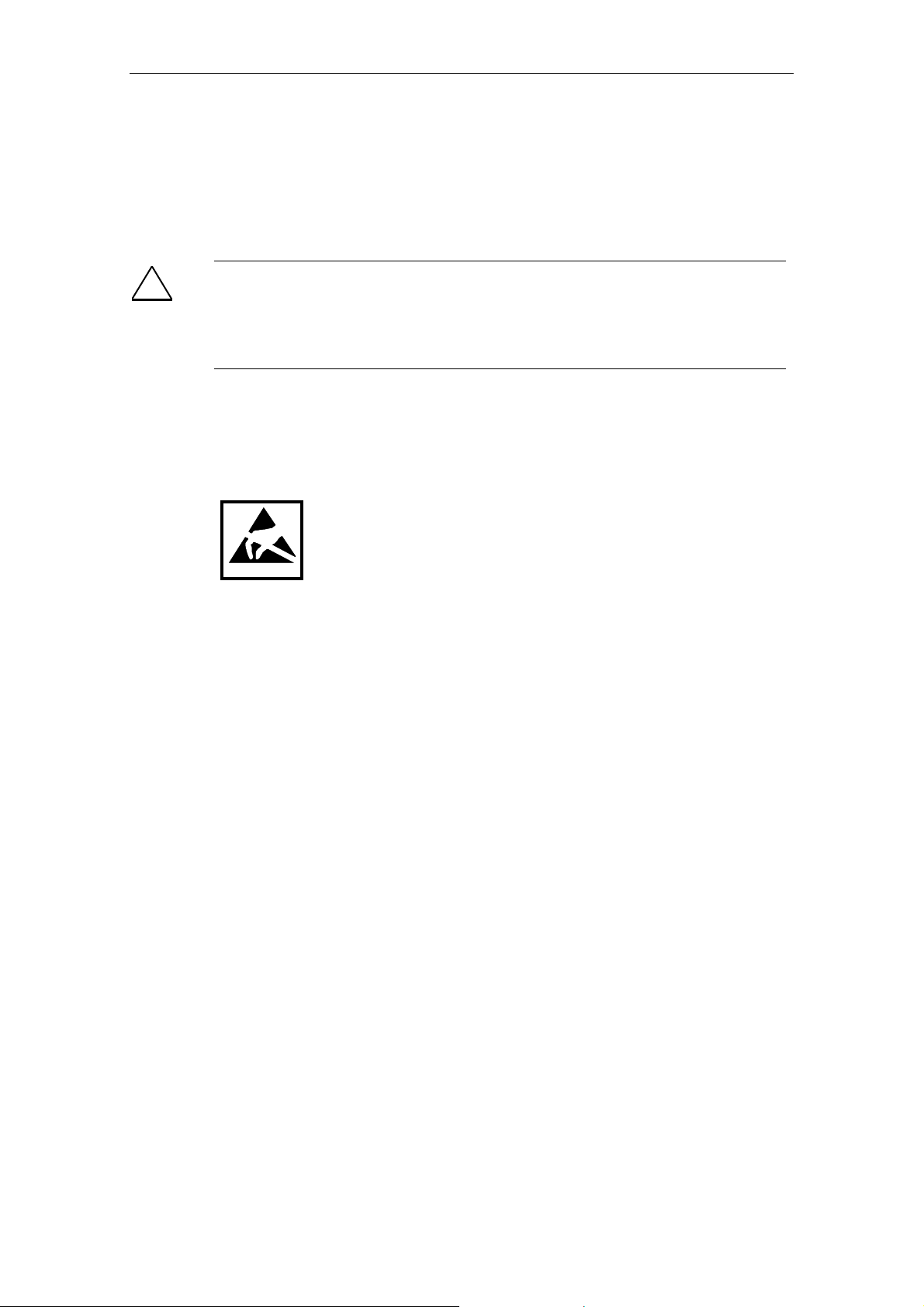
Modules containing electrostatically sensitive devices (ESDs) can be identified by
the following label:
Please observe and carefully follow the guidelines mentioned below when handling
modules equipped with electrostatically sensitive devices:
• Always discharge your body before handl ing m odules equippe d with ES Ds (f or
example, by touching a grounded object).
• Devices and tools must be free of static electricity.
• Always pull the power plug and disconnect the battery before connecting or
disconnecting modules (containing ESDs).
• Touch modules fitted with ESDs by their edges only.
• Never touch wiring posts or printed conductors on modules containing ESDs.
For more information on electronic charging and safety measures, refer to
Appendix A.
SIMATIC Rack PC IL 40, Getting Started
1-4 A5E00171493-02
Page 13

1.2 Certificates, Directives and Declarations
Notes on the CE Symbol
The following applies to the SIMATIC product described in this Getting Started:
EMC Directive
This product fulfils the requirements for the EC directive 89/336/EEC on
„electromagnetic compatibility" and the following fields of application apply
according to this CE symbol:
Field of Application Requirement For
Emitted Interference Noise Immunity
Residential and commercia l
areas and small businesses.
Industry EN 50081-2: 1992 EN 61000-6-2
EN 50081-1: 1992 EN 61000-6-2
Important Information
In addition, the EN 61000-3-2 (harmonic currents) and EN 61000-3-3 (voltage
fluctuation and flicker) have been fulfilled.
Low Voltage Directive
This product fulfils the requirements for the EC directive 73/23/EEC on „low
voltage" and was tested to EN60950.
Declaration of Conformity
The EC declarations of conformity and the documentation relating to this are
available to the authorities concerned, according to the above EC directive, from:
Siemens AG
Bereich Automation and Drives
A&D AS RD 4
Postfach 1963
D-92209 Amberg
Tel.: +49 (9621) 80-3283
Fax: +49 (9621) 80-3278
SIMATIC Rack PC IL 40, Getting Started
A5E00171493-02
1-5
Page 14

Important Information
Observing the Setup Guidelines
The setup guidelines and safety instructions given in this Getting Started must be
observed on startup and during operation.
Connecting Peripherals
The requirements regarding noise immunity (EN61000-6-2) are met when you
connect a peripheral suitable for an industrial environment. Peripherals should only
be connected via shielded cables.
Software License Agreement
The SIMATIC Rack PC IL is shipped with the operating system on the Restore CD.
Please obse rve the relevant license agreements.
SIMATIC Rack PC IL 40, Getting Started
1-6 A5E00171493-02
Page 15

Important Information
1.3 Certification for the USA, Canada and Australia
Security
One of the following markings on a device is indicative of the corresponding
approval:
Underwriters Laboratories (UL) to the UL 1950 Standard (I.T.E)
C
C US
or to the UL508 (IND.CONT.EQ)
Underwriters Laboratories (UL) to the Canadian Standard C22.2 No. 950
(I.T.E) or to the C22.2 No. 142 (IND.CONT.EQ)
Underwriters Laboratories (UL) to Standard UL 1950, Report E11 5352 and to the
Canadian Standard C 22.2 No.950 (I.T.E)
or to the UL508 and C22.2 No. 142 (IND.CONT.EQ)
UL-Recognition-Mark
Canadian Standard Association (CSA) to standard C22.2. No. 950
(LR 81690) or to C22.2 No. 142 (LR 63533)
EMC
Canadian Standard Association (CSA) to the American Standard UL 1950
(LR 81690)
NRTL
USA
Federal Communications Commission
Radio Frequency Interference Statement
This equipment has been tested and found to comply with the limits for a
Class A digital device, pursuant to Part 15 of the FCC Rules. These limits are
designed to provide reasonable protection against harmful interference when
the equipment is operated in a commercial environment. This equipment
generates, uses, and can radiate radio frequency energy and, if not installed
and used in accordance with the instruction manual, may cause harmful
interference to radio communications. Operation of this equipment in a
residential area is likely to cause harmful interference in which case the user
will be required to correct the interference at his own expense.
Shielded Cables
Shielded cables must be used with this equipment to maintain compliance
with FCC regulations.
Modifications
Changes or modifications not expressly approved by the manufacturer could
void the user's authority to operate the equipment.
Conditions of Operations
This device complies with Part 15 of the FCC Rules. Operation is subject to
the following two conditions: (1) this device may not cause harmful
interference, and (2) this device must accept any interference received,
including interference that may cause undesired operation.
SIMATIC Rack PC IL 40, Getting Started
A5E00171493-02
1-7
Page 16

Important Information
1.4 Transport
Transporting
Despite the fact that the Rack PC IL is of rugged design, its internal components
are sensitive to severe vibrations or shock. You must therefore protect the PC from
severe mechanical stress when transporting it.
Use the original packing material if you have to ship the Rack PC IL from one
location to another.
!
Caution
Risk of damage!
When transporting the PC in cold weather, when it may be submitted to extreme
variations in temperature, make sure that there is no moisture (condensation) on
or in the PC.
The PC must be allowed to reach room temperature slowly before you switch it
on.
SIMATIC Rack PC IL 40, Getting Started
1-8 A5E00171493-02
Page 17

2 Commissioning
2.1 Unpacking the SIMATIC Rack PC IL
Unpack your Rack PC IL as follows:
1. Remove the packing.
2. Do not throw the original packing away. Keep it in case you have to transport
the unit again sometime in the future.
3. Please keep the documentation in a safe place. It is required during the initial
start up and is part of the device.
4. Check the packing and its contents for any shipping or transport damage
5. Check with the delivery note to make sure no components are missing. Also
check the accessory parts, which you can order separately.
6. Please inform your local dealer of any shipping or transport damages and of
outstanding items indicated on the delivery note.
Recording the Serial Number and the Ethernet address
7. Enter the serial number and the Ethernet address of your PC in the table
below. You can find the serial number on the type label attached to the rear of
the device. The Ethernet address can be found in the BIOS setup under Info
(key F1) > LAN Address.
The device can precisely be identified with the help of these numbers in case
of repairs or theft.
Enter the Microsoft Windows “Product Key" from the “Certificate of Authenticity"
8. Enter the Microsoft Windows "Product Key" from the "Certificate of
Authenticity" (COA) in the table. The product key is on the back of the device.
F-No.
Order No.
Microsoft Windows Product Key
Ethernet Address
SIMATIC Rack PC IL 40, Getting Started
A5E00171493-02
2-1
Page 18

Commissioning
2.2 Installing the SIMATIC Rack PC IL
The Rack PC is suitable for vertical and horizontal fitting in consoles, switch boards
and 19" rack systems.
Notice
In the event of a vertical installation, make sure the right side of the device faces
up.
The Rack PC IL meets the requirements for a fire enclosure to EN 60950. It can
therefore be fitted without an additional fire enclosure.
Please note the following points when installing the PC:
• Avoid extreme ambient conditions as far as possible. Protect your PC from
dust, moisture, and heat.
• Keep the PC out of direct sunlight.
• Mount the PC as safely as possible to prevent any danger (for example, by
falling over).
• The clearance near the ventilation slots must be at least 50 mm, so that the PC
is sufficiently ventilated.
• Make certain that the ventilation slots for the housing are not covered.
• Make certain that the sliding door in front of the drives is closed during
operation.
• The Rack PC IL can be mounted on telescopic rails or on cabinet brackets. It is
not permitted to mount it at the 19" front supports only.
• Use the respective manufacturer's cabinet or rack slide rails or L-sections.
Contact your cabinet supplier directly regarding cabinet or rack installation.
• The use of the telescopic rails makes it possible to completely pull the Rack
PC out of the cabinet or rack.
Notice
If the systems are installed without keeping to the conditions mentioned above,
the approvals pursuant to UL 1950 and EN60950 are no longer valid!
SIMATIC Rack PC IL 40, Getting Started
2-2 A5E00171493-02
Page 19
Commissioning
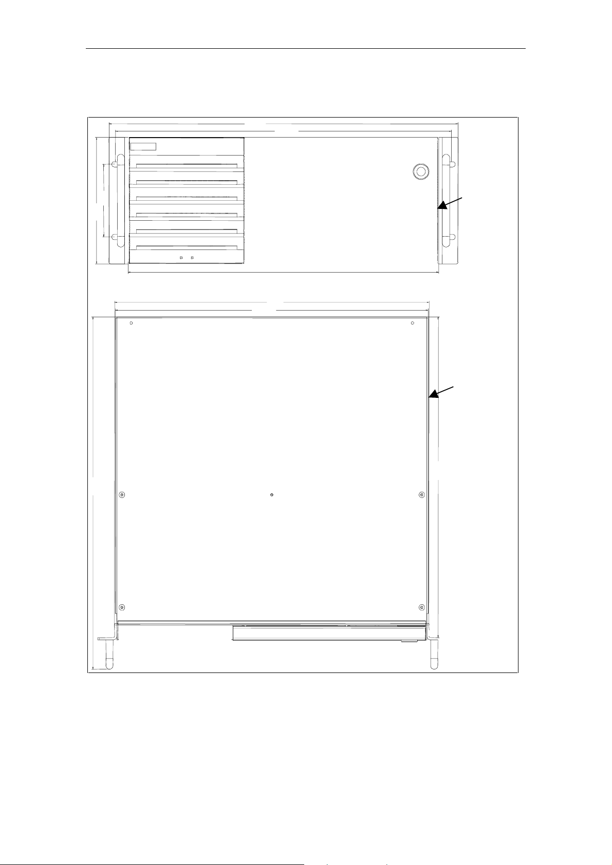
Dimensioned Drawing for installation in cabinet 19"
483
465
101
177
430
436
433,6
Upwards for
vertical
installation
Upwards f or
vertical
installation
446
490
SIMATIC Rack PC IL 40, Getting Started
A5E00171493-02
2-3
Page 20
Commissioning
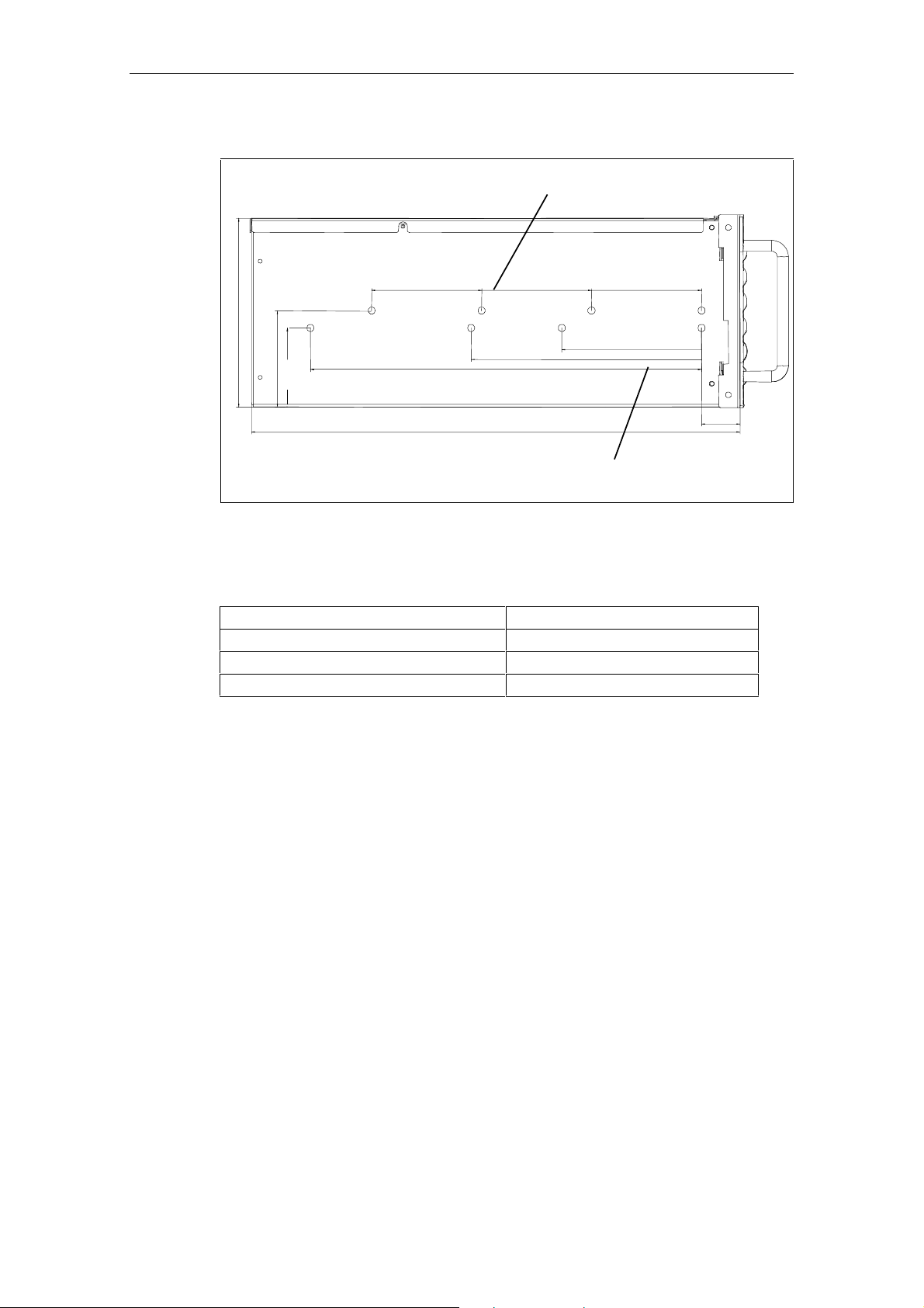
Dimensioned Drawing for using telescopic rails
Dimensions for telescopic rails
by the company Rittal type 3659
100
173,3
88,5
72,6
355,6
Technical Specifications of the Telescopic Rails
Load per pair minimum 30 kg
Pull-out length for complete pull-out minimum 470 mm
Rail thickness maximum 9,7 mm
Fixing screws M5 x 6mm
The fixing screw of the telescopic rail should not go beyond a maximum of 5 mm
into the housing.
100
209,6
444,5
Dimensions for telescopic ra ils by the
company Schroff type 69000-122
100
127
35
SIMATIC Rack PC IL 40, Getting Started
2-4 A5E00171493-02
Page 21
Commissioning
2.3 Preparing for Operation
Connection to the Power Supply Unit
The AC power supply unit of the Rack PC IL is designed for 115/230V systems.
Voltage selection is carried out automatically.
1. Plug the supplied power cable into the appliance connector.
2. Connect the unit to a socket outlet with a grounded protective conductor.
3. Fasten the power plug using power plug clamp supplied.
!
Warning
The Rack PC IL is equipped with a safety-tested mains cable and may only be
connected to a grounded grounding outlet.
Make sure that the socket on the device or the grou nd ing out let of the bui ld ing
installation is easily accessible and as near as possible to the device.
The mains plug must be pulled out for complete mains separation. This point
must be easily accessible. If the PC is installed in a cabinet, there must be a
central mains disco nnector.
Notice
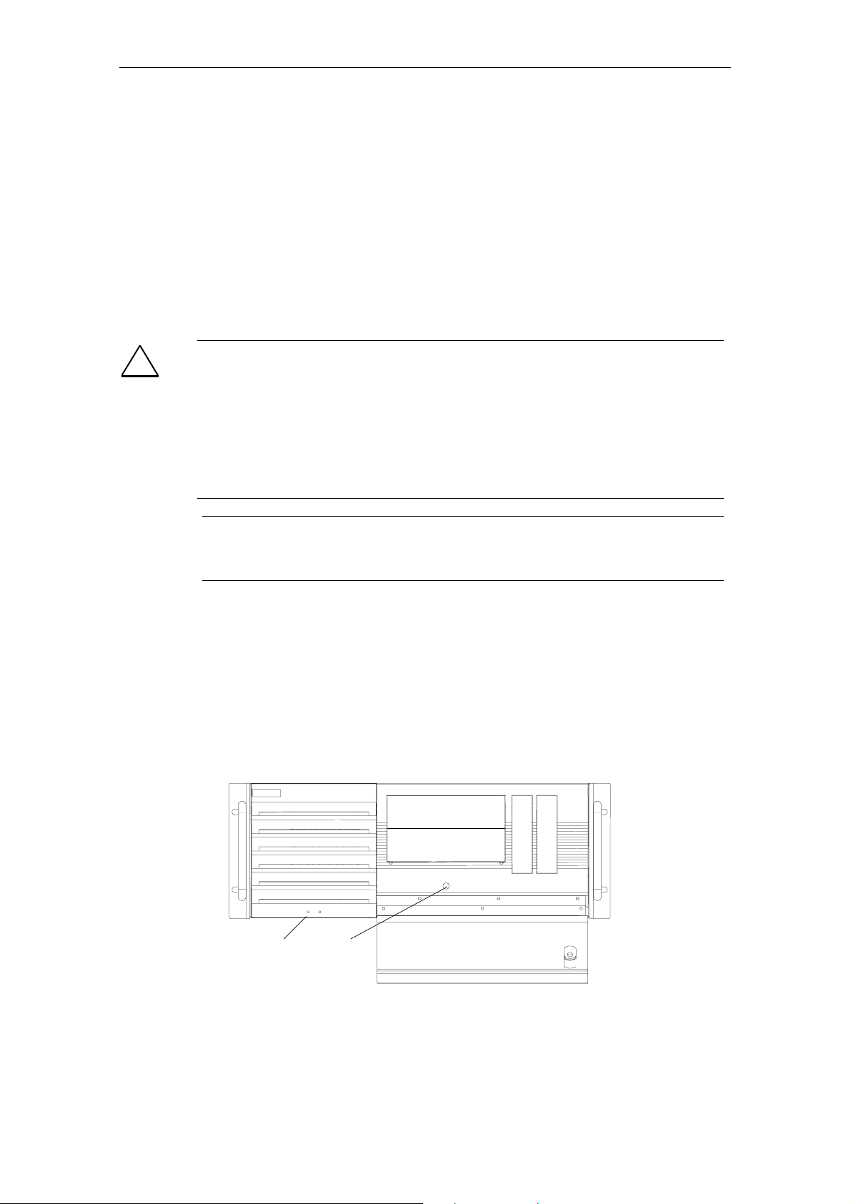
Rack IL 40 starts to run as soon as it is connected to the power supply. Press
the ON/OFF button to switch it off again.
Connecting the Peripheral Units and Switching on the Rack PC IL
Before you connect the Rack PC IL to the mains, the peripheral units mouse,
keyboard and monitor must be connected.
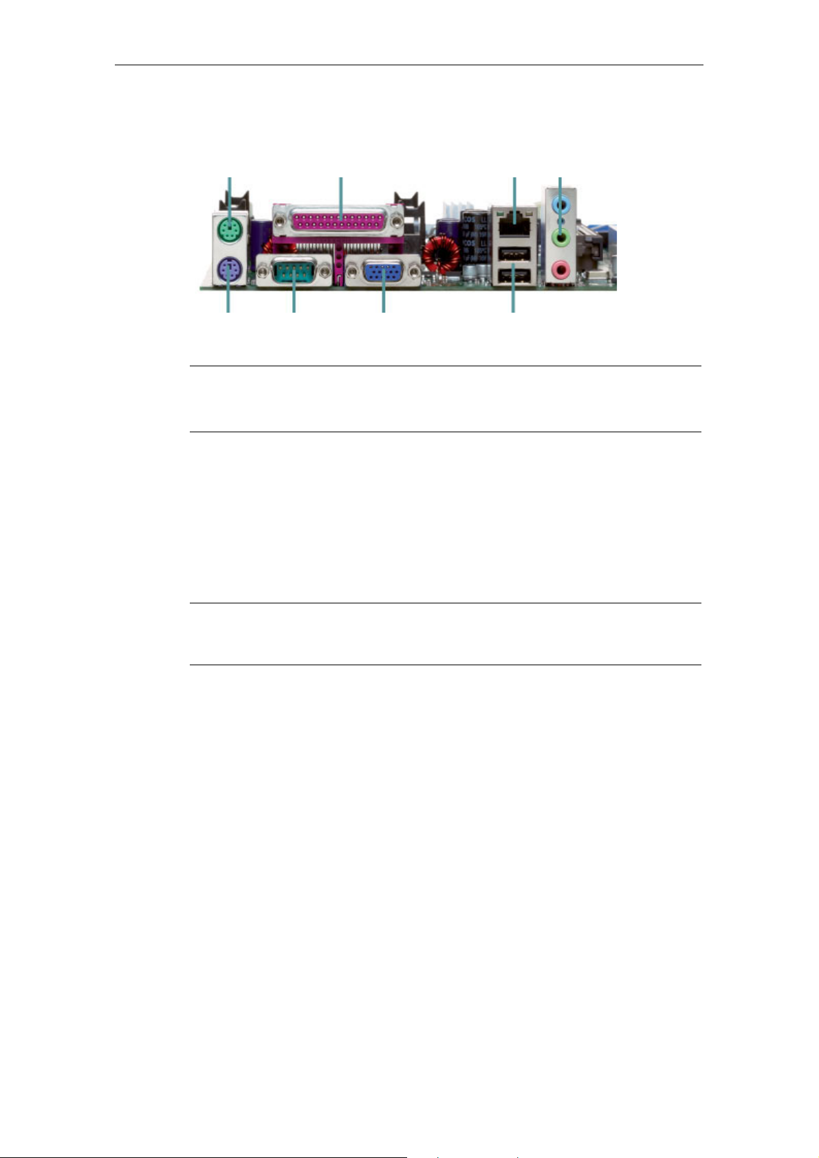
1. Insert the connector cable of the peripheral units into the corresponding
sockets on the port side of the Rack PC IL (see Section 2.6.)
2. Press the On/Off button behind the front door, the PC is in operation. The
Power LED lights green.
Power LED On/Off
SIMATIC Rack PC IL 40, Getting Started
A5E00171493-02
button
2-5
Page 22

Commissioning
2.4 Initial Startup
The Rack PC IL is delivered without any operating system installed. The operating
system is contained on the supplied Restore CD ROM.
The Rack PC IL is currently approved for the following operating systems:
• Windows NT 4.0; German, English
• Windows 2000 Professional MUI;
German, English, French, Italian, Spanish
• Windows XP Professional MUI;
German, English, French, Italian, Spanish
During the installation, the partitions
Windows XP) and
the hard disk drive.
Note
You require the corresponding LAN boot support in the BIOS if you want to boot
the device from the network. PXE support is implemented in the BIOS during
delivery. If you require BOOTP support, you have to install it first. You wi ll fin d
the tool for it in the "Rack PC IL 40 Documentation and Drivers" CD supplied.
Installing the Operating System from Restore CD
After switching on, the Rack PC IL will perform a self test. During the self test, the
message
Notice
The keys F2 and F12 can be used to recall the displayed menus while the
message is displayed. Only press the keys if you are familiarized with the menus
to be recalled.
The Rack PC IL is booted. The message Operating system not found
appears on the screen to indicate that no operating system has been installed yet.
<F2> BIOS Setup, <F12> Boot Menu appears briefly.
d:\data with the remaining memory capacity are created on
c:\prog with 4 Gbytes (or 10 Gbytes for
1. Insert the supplied Restore CD into the CD ROM drive and close it.
Notice
If two CD drives are installed, the CD in has to be placed in the first drive (master).
2. Press twice the On/Off button behind the front door. The Rack PC IL is
rebooted and the recovery menu appears.
3. If you select "Full Recovery", the hard disk will be overwritten completely. If you
select "Partial Recovery", the data on "D" (Partition DATA) will be retained.
Always select "Full Recovery" for the first commissioning.
"Partial Recovery" can only be used for reinstallation if the partition name and,
if applicable, the partition size are not changed.
SIMATIC Rack PC IL 40, Getting Started
2-6 A5E00171493-02
Page 23

Commissioning
4. Remove the CD-ROM from the drive after installation.
5. Restart your PC.
Initial Startup
Note
The procedure below describes, as an example, the first commissioning of a
Rack PC IL with the operating system Windows 2000, German.
The start-up window of the operating system appears.
In case of new hardware, the dialog for hardware installation appears. Confirm the
hardware installation.
The start-up window of the operating system reappears. Select and confirm your
system settings. The Rack PC IL is booted.
After restart
• the time zone must be set and
• the license contract must be confirmed.
Confirm your settings – the system settings are updated now.
Then, the date/time dialog is opened. Enter the correct date/time, if necessary, and
confirm your settings.
Close Windows and restart the Rack PC to fully integrate the upgraded.
SIMATIC Rack PC IL 40, Getting Started
A5E00171493-02
2-7
Page 24

Commissioning
2.5 Normal Operation
Once the Rack PC's operating system is set up, the user interface of the operating
system is displayed following system startup every time you switch on or reset the
PC.
Initial Start
To switch on the Rack PC IL press the On/Off button twice. After switching on, the
Rack PC IL will perform a self test. During the self test, the message
Setup, <F12> Boot Menu
At the conclusion of the self test, the operating system will be loaded and the
desktop be displayed.
Special Features, Windows 2000
Auto-Logon is not activated in the state of delivery:
In order to activate Auto-Logon, perform the following settings:
1. Select Start > Settings > Control Panel > Users and Passwords:
<F2> BIOS
appears briefly.
2. Deactivate the check box "Users and enter user name and password for the
computer".
3. Apply the settings and enter the password.
Special Features, Windows XP Professional
Auto-Logon is activated in the state of delivery.
You will find the tool for switching Autologon On/Off under "Driver&Updates" on the
"Rack PC IL 40 Documentation and Drivers" CD supplied.
Special Features, Windows NT4
The DHCP service is installed during the installation of Windows NT. The DHCP
service is deactivated by default.
Activate the DHCP service as follows if you want to use it:
1. Select Start > Settings > Control Panel > Services. The services dial og box
opens.
2. Select DHCP Client service. A double-click opens the Services window.
3. Select Automatically and confirm your selection with OK.
4. Close the opened window.
Bear in mind that the ramp-up time of the computer increases considerably when
the DHCP service is activated, however if the Rack IL is not connected to a
corresponding network .
SIMATIC Rack PC IL 40, Getting Started
2-8 A5E00171493-02
Page 25
Commissioning
2.6 Connecting Peripheral Units
PS/2 Mouse LAN
PS/2
Keyboard
Serial
Notice
When connecting peripher al unit s, en sur e that the co mponents have industria l
capability according to EN 50082-2.
Connecting a PS/2 Keyboard
A PS/2 keyboard of your choice can be connected to the Rack PC IL.
1. Separate the PC from the mains.
2. Insert the plug of the PS/2 keyboard.
Parallel
VGA
Audio
USB A&B
3. Reconnect the PC to the mains.
Caution
It is recommended that a keyboard with straight keyboard connector is used, so
that the connector does not obsc ure ad ja ce nt por ts .
Connecting a USB Keyboard
You can find out how to connect a USB keyboard in Connecting USB devices.
Using a Mouse
You can connect a PS/2 mouse as well as a USB mouse to the Rack PC IL. The
USB port is only supported by Windows 2000 and Windows XP.
SIMATIC Rack PC IL 40, Getting Started
A5E00171493-02
2-9
Page 26

Commissioning
Connecting a PS/2 Mouse
You can connect an external PS/2 mouse or another external pointing device to an
additional PS/2-compatible mouse connector.
1. Separate the PC from the mains.
2. Plug the cable of the PS/2 mouse or another external pointing device into the
mouse connector "PS/2 mouse".
3. Reconnect the PC to the mains.
Connecting a Serial Mouse
You can connect a serial mouse to the serial port. To operate a serial mouse, the
appropriate mouse driver must be initialized and assigned parameters. You will find
the information you need to do this in the description for your mouse or in the
description for the operating system.
1. Separate the PC from the mains.
2. Plug the serial mouse into the "Serial" port.
3. Secure the connector with the screws.
4. Reconnect the PC to the mains.
Connecting a USB Mouse
You can find out how to connect a USB mouse in Connecting USB devices.
Connecting Monitors
You connect external multisynchronous monitors using the standard VGA
connector on the right-hand panel side of the unit. We recommend that you use a
Siemens monitor.
You must switch the PC off before connecting the monitor cable.
1. Separate the PC from the mains and switch the monitor off.
2. Insert the monitor lead in the VGA socket.
3. Screw down the plug.
4. Connect the monitor cable to the monitor.
5. Reconnect the PC to the mains and switch the monitor on.
Caution
If you want to set higher clock frequencies and resolutions, first make sure that the
monitor you are using is suitab le for a higher cl oc k fre que nc y and res olu tion.
If the clock frequency is too high, this can cause damage to the monitor.
SIMATIC Rack PC IL 40, Getting Started
2-10 A5E00171493-02
Page 27

Commissioning
Connecting the Printer to the Parallel Port
1. Separate the PC from the mains and switch off the printer.
2. Plug the printer cable into the LPT1 parallel port.
3. Connect the printer cable to the printer.
4. Screw the connector tight at the interface port.
5. Reconnect the PC to the mains and switch the printer on.
Note
You can configure the parallel interface in the BIOS setup. The ECP mode is set
by default in the delivery condition.
Caution
Switch the unit off before connecting the parallel printer to the "Parallel" port (the
printer should also be switch ed off) .
Make sure that you use the correct port. If you use the wrong port or wrong
connecting cables, the port may be damaged.
Before plugging in the cables, the electrostatic charge of your body, the unit, and
the cables must be equalized. To do this, touch the mounting plate for the ports on
the left-hand side of the unit. Only use original connecting cables.
Connecting the Printer to a USB Port
You can find out how to connect a USB printer in Connecting USB devices.
Connecting USB Devices
Single as well as several USB devices (mouse, keyboard or printer) can be
connected to a USB port.
• Insert the plug of the USB device into the USB port.
The device is recognized by the Plug and Play operating system and is then
available.
A USB keyboard can be used to manipulate the BIOS setup. To do this, the "USB
Legacy Support“ in the BIOS Setup has to be activated.
Notice
Operating systems which do not support Plug and Play (e.g. WindowsNT)
generally do not allow the use of USB device s.
SIMATIC Rack PC IL 40, Getting Started
A5E00171493-02
2-11
Page 28

Commissioning
2.7 Ethernet (RJ45 Ethernet Port)
Networking the Rack PC via the RJ45 Ethernet Port
The RJ45 Ethernet port is a Twisted Pair (TP) port with a data transfer rate of
10/100 Mbps. The onboard port is compatible with the Intel 82562 adapter.
The port is Plug and Play capable and is automatically recognized in Windows. The
log settings are carried out in the Windows control panel.
Notice
A class 5 Ethernet cable is required to operate their 100 Mbps.
Note
The Rack IL 40 LAN Controller supports AlertOnLAN and WakeOnLAN.
2.8 Connection under Windows
Windows supports point-to-point connections via the LPT or COM port. The
required connecting cables are standard, commercially available products. More
information is available in the online Help system under "Connection to Another
Computer".
SIMATIC Rack PC IL 40, Getting Started
2-12 A5E00171493-02
Page 29

3 Operating
3.1 Switch on the PC
1. Switch on the monitor (refer to the operating instructions of the screen).
2. Press the On/Off button behind the front door. The Power LED lights green, the
PC is in operation.
Notice
If you have assigned the system password, you must enter this when requested to
do so in order to start the operating system.
3.2 Switch off the PC
If you are working with Windows, always use Start > Shut down in the task bar for
switching off your PC.
If the PC's operating system does not shut down automatically, switch it off on the
prompt to do so with the on-off switch at the back of the front door. The power LED
is not lit.
Caution
To disconnect the device from the power supply, turn off the power switch in the
control cabinet/control panel or pull out the power switch on Rack PC IL.
Placing a PC (with soft power off function) in a ready-to-operate-s tate by means of
software.
After quitting the operating system, the PC automatically shuts down using the soft
power off function (ready to run).
Notice
This function is not available under Windows NT.
SIMATIC Rack PC IL 40, Getting Started
A5E00171493-02
3-1
Page 30

Operating
3.3 Operating modes
PC is switched off
The power switch in the control cabinet/control panel is off or the mains plug is
removed, the power LED is not lit, and the On/Off button is disabled.
PC is ready-to-operate
The power switch in the control cabinet/control panel is on or the mains plug is
inserted, the power LED is not lit. You can switch the PC on with the On/Off button.
The "ready-to-operate" status corresponds to the "standby" status of a TV set. The
description of the power-on indicator can be found in section 3.5.
PC switched on
The On/Off button has been actuated, the power LED lights green.
3.4 Reset via On/Off button
If you press the On/Off button briefly once the operating system will shut down and
Rack PC IL is switched off.
Notice
With Windows NT the PC switched off imme diately since the system can not be
shut down.
If you press the On/Off button once for more than four seconds, the Rack PC IL will
be switched off, without shutting down the operation system (Reset). Briefly
pressing the On/Off button again will restart the operating system.
SIMATIC Rack PC IL 40, Getting Started
3-2 A5E00171493-02
Page 31

3.5 LEDs at the PC
The LEDs are located at the front side of the housing.
Hard Disk Drive
The LED lights up when hard disk drive is being accessed.
Power
The LED lights orange The PC is in operation.
The LED is not lit The PC is switched off or ready for operation.
CD ROM
The LED lights up when CD ROM drive is being accessed. You may only remove
the CD when the LED is unlit.
Operating
Floppy Disk
The LED lights up when floppy disk drive is being accessed. You may only remove
the floppy disk when the LED is unlit.
3.6 Monitoring Functions
The following monitoring functions are implemented:
• Temperature monitoring
• Watchdog
• Fan monitoring
For this functions you will find the software "System Guard" and "Desk View on the
supplied CD "Rack PC IL 40 Documentation and Drivers“.
Notice
The Software "System Guard" and "Desk View" are not to be installed
simultaneously.
or operation might cause errors.
You will find a comprehensive description of the monitoring functions in the
technical manual on system modules on the supplied CD "Rack PC IL 40
Documentation and Drivers".
Since both of them access the same interface, parallel installation
SIMATIC Rack PC IL 40, Getting Started
A5E00171493-02
3-3
Page 32
Operating
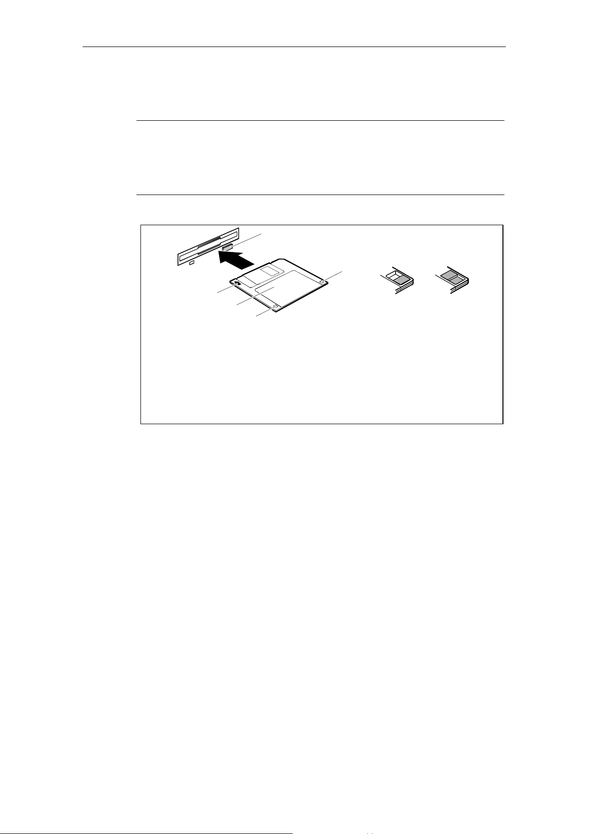
3.7 Floppy Disk Drive
Caution
Risk of Data loss!
You must not press while the eject button the drive's green access LED is lit.
Do not use the disk drive when the Rack PC IL is exposed to vibrations and
shock.
5
4
6
7
1
2
3
1 = Insertion direction
2 = Label area
3 = Write protection tab for a 1.44 Mbyte floppy disk
4 = Ident ification of a 1.44 MB flopp y dis k or wr it e pro t ec t s wit ch on a 120 MB fl opp y di sk
5 = Eject button for inserted floppy disks
6 = Disk is write-protected
7 = Disk is not write-protected
SIMATIC Rack PC IL 40, Getting Started
3-4 A5E00171493-02
Page 33

3.8 CD R/RW Drive
Depending on the device configuration, it can come with a CD R or a CD RW drive.
For example, you can read the electronic manual of the supplied CD with this drive.
Caution
CD drives are sensitive to vibrations and shock. Any vibrations occurring
during operation can lead to damag e to the drive or stor age medi um.
Do not use the disk drive when the Rack PC IL is exposed to vibrations and
shock.
Burner Software
To be attain the full functionality of the CD RW drive, burner software is necessary.
You can find it on the CD included in the delivery of the device. To install the
software place the CD in the drive and follow the instructions on the screen.
The burning operation is only permissible in an untroubled environment and under
an ambient temperature not exceeding 35°C.
Operating
Caution
Risk of data error when burning a CD-RW!
The quality of recordable CDs vary considerably, data error can therefore not be
completey ruled out when writing a CD, even when no error message is
displayed. Correctly written data can on ly be guar ante ed by an add iti on al
comparison with the source dat a. To ensur e an er ror - free cop yi ng proc es s do a
data comparison after every bur ni ng se s sion.
SIMATIC Rack PC IL 40, Getting Started
A5E00171493-02
3-5
Page 34

Operating
3.9 BIOS-Settings
You can set up the system functions and the hardware configurations of your PC in
the BIOS.
Before delivery, the BIOS of the Rack PC IL is set differing from the standard
BIOS settings as follows:
Register
Main Boot Options Å Post Errors: No Halt On Any Errors
Advanced Power On/Off Å Power Failure
Recovery:
System Management Å Fan Control Enhanced
Power APM: Disabled
Power Management Mode: Disabled
ACPI S3: Disabled
Option Settings
Alwa ys On
The technical manual on system modules or the manual "BIOS Setup" shows you
how to call and operate the BIOS Setup. The manual also contains detailed
descriptions of the menus and setting options offered by the BIOS Setup.
Notice
Updating BIOS or calling the "Default settings" function changes the BIOS
settings. Reset the BIOS according to the specifications on the table.
Pay special attention to making the settings in the index Power correctly.
All menu items are disabled by default.
The operating system's functions "Save to RAM" (standby) and "Save to Disk"
(hibernate) are not enabled functions for Rack PC IL.
SIMATIC Rack PC IL 40, Getting Started
3-6 A5E00171493-02
Page 35

3.10 Property and data protection
Software functions and mechanical locking offer a broad range of functions for
protecting your PC and your personal data from unauthorized access. You can also
combine these functions.
3.10.1 Mechanical housing lock
Your PC will be supplied with a housing lock; you can lock its front door with it to
deny access to unauthorized persons.
3.10.2 Access protection under Windows
Under Windows you can activate a screen saver and protect it with a password.
Only those users who know the password can deactivate the screen saver and
access any open files. Detailed information on screen savers is provided by the
associated help function.
Operating
3.10.3 BIOS Setup security functions
The Security menu in BIOS Setup offers you various options for protecting your
personal data against unauthorized access, e.g.:
• Preventing unauthorized BIOS Setup entry
• Preventing unauthorized system access
• Preventing unauthorized access to the settings of boards with their own BIOS
• Preventing system booting from the diskette drive
• Activating virus warnings
• Preventing unauthorized writing of diskettes
• Protecting BIOS from being overwritten
• Protecting the PC from being switched on by an external device
You can also combine these functions.
You will find a detailed description of the Security menus and how to assign
passwords in the technical manual for the system board or in the "BIOS Setup"
manual.
SIMATIC Rack PC IL 40, Getting Started
A5E00171493-02
3-7
Page 36

Operating
SIMATIC Rack PC IL 40, Getting Started
3-8 A5E00171493-02
Page 37

A Guidelines for Handling Electrostatically-
Sensitive Devices (ESD)
A.1 What is ESD?
Definition
All electronic modules are equipped with large-scale integrated ICs or components.
Due to their design, these electronic elements are very sensitive to overvoltages
and thus to any electrostatic discharge.
These Electrostatically-Sensitive Devices are commonly referred to by the
abbreviation ESD.
Electrostatically-sensitive devices are labeled with the following symbol:
!
Caution
Electrostatically-sensitive devices are subject to voltages that are far below the
voltage values that c an still be perceived by human beings. These voltages are
present if you touch a component or the electrical connections of a module
without previously being electrostatically discharged. In most cases, the damage
caused by an overvoltage is not immediately noticeable and results in total
damage only after a prolonged period of oper at io n.
SIMATIC Rack PC IL 40, Getting Started
A5E00171493-02
A-1
Page 38
Guidelines for Handling Electros tat ic al ly-Sensitive Devices (ESD)
80
Rela t iv e a ir h u midity in %
Synthetics
A
A.2 Electrostatic Charging of Persons
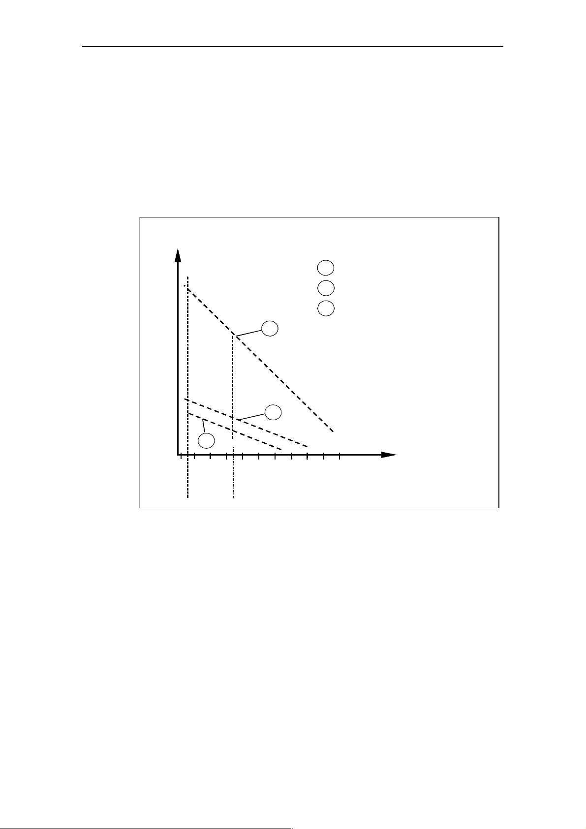
Charging
Every person with a non-conductive connection to the electrical potential of its
surroundings can be charged electrostatically.
Figure 7-1 shows you the maximum values for electrostatic voltages which can
build up on a person coming into contact with the materials indicated in the figure.
These values are in conformity with the specifications of IEC 801-2.
Voltage in kV
(kV)
16
15
14
13
12
10
11
1
9
8
7
6
5
4
3
2
1
3
2
1
Wool
2
ntistatic material, for example,
3
wood or concrete
510
20 30 40 50 60 70
Figure 7-1 Electrostatic Voltages which can Build up on a Person
90 100
A-2 A5E00171493-02
SIMATIC Rack PC IL 40, Getting Started
Page 39

Guidelines for Handling Electros tat ic al ly-Sensitive Devices (ESD)
A.3 General Protective Measures Against Electrostatic
Discharge Damage
Ensure Sufficient Grounding
Make sure that the personnel, working surfaces, and packaging are sufficiently
grounded when handling electrostatically-sensitive devices. You thus avoid
electrostatic charging.
Avoid Direct Contact
You should touch electrostatically-sensitive devices only if it is unavoidable (for
example, during maintenance work). Hold modules without touching the pins of
components or printed conductors. In this way, the discharged energy cannot affect
the sensitive devices.
If you have to carry out measurements on a module, you must discharge your
body's electrostatic charge before you start the measurement by touching
grounded metallic parts. Use grounded measuring devices only.
SIMATIC Rack PC IL 40, Getting Started
A5E00171493-02
A-3
Page 40

Guidelines for Handling Electros tat ic al ly-Sens i tiv e Devic es (ESD)
SIMATIC Rack PC IL 40, Getting Started
A-4 A5E00171493-02
 Loading...