

Page 1
Page 2

PROFINET with STEP 7 V14
___________________
___________________
___________________
___________________
___________________
___________________
SIMATIC
PROFINET
PROFINET with STEP 7 V14
Function Manual
09/2016
A5E03444486
Preface
Documentation guide
1
Description
2
Parameter
assignment/addressing
3
Diagnostics
4
Functions
5
-AG
Page 3

Siemens AG
Division Digital Factory
Postfach 48 48
90026 NÜRNBERG
GERMANY
A5E03444486-AG
Ⓟ
Copyright © Siemens AG 2013 - 2016.
All rights reserved
Legal information
Warning notice system
DANGER
indicates that death or severe personal injury will result if proper precautions are not taken.
WARNING
indicates that death or severe personal injury may result if proper precautions are not taken.
CAUTION
indicates that minor personal injury can result if proper precautions are not taken.
NOTICE
indicates that property damage can result if proper precautions are not taken.
Qualified Personnel
personnel qualified
Proper use of Siemens products
WARNING
Siemens products may only be used for the applications described in the catalog and in the relevant technical
ambient conditions must be complied with. The information in the relevant documentation must be observed.
Trademarks
Disclaimer of Liability
This manual contains notices you have to observe in order to ensure your personal safety, as well as to prevent
damage to property. The notices referring to your personal safety are highlighted in the manual by a safety alert
symbol, notices referring only to property damage have no safety alert symbol. These notices shown below are
graded according to the degree of danger.
If more than one degree of danger is present, the warning notice representing the highest degree of danger will
be used. A notice warning of injury to persons with a safety alert symbol may also include a warning relating to
property damage.
The product/system described in this documentation may be operated only by
task in accordance with the relevant documentation, in particular its warning notices and safety instructions.
Qualified personnel are those who, based on their training and experience, are capable of identifying risks and
avoiding potential hazards when working with these products/systems.
Note the following:
documentation. If products and components from other manufacturers are used, these must be recommended
or approved by Siemens. Proper transport, storage, installation, assembly, commissioning, operation and
maintenance are required to ensure that the products operate safely and without any problems. The permissible
All names identified by ® are registered trademarks of Siemens AG. The remaining trademarks in this publication
may be trademarks whose use by third parties for their own purposes could violate the rights of the owner.
We have reviewed the contents of this publication to ensure consistency with the hardware and software
described. Since variance cannot be precluded entirely, we cannot guarantee full consistency. However, the
information in this publication is reviewed regularly and any necessary corrections are included in subsequent
editions.
for the specific
08/2016 Subject to change
Page 4

Preface
Purpose of the documentation
Basic knowledge required
Scope
This function manual provides an overview of the PROFINET communication system with
SIMATIC STEP 7 V14.
STEP 7 V14 is integrated into the powerful graphical Totally Integrated Automation Portal
(TIA Portal), the new integration platform for all automation software tools.
This function manual supports you in planning a PROFINET system. The manual is
structured into the following subject areas:
● PROFINET basics
● PROFINET diagnostics
● PROFINET functions
The following knowledge is required in order to understand the manual:
● General knowledge of automation technology
● Knowledge of the industrial automation system SIMATIC
● Knowledge about the use of Windows-based computers
● Knowledge about how to use STEP 7 (TIA Portal)
This documentation is the basic documentation for all SIMATIC products from the
PROFINET environment. The product documentation is based on this documentation.
The examples are based on the functionality of the S7-1500 automation system.
PROFINET with STEP 7 V14
4 Function Manual, 09/2016, A5E03444486-AG
Page 5

Preface
Changes compared to previous version
Function
Applications
User benefits
line.
processing.
By sending the cyclic IO data in both directions in
with MRP.
performance.
demand.
Conventions
STEP 7:
Note
A note contains important information on the product, on handling of the product and on the
section of the documentation to which you
See also
This manual encompasses the following new functions compared to the previous version
(version 12/2014):
PROFINET IO on the 2nd
PROFINET interface
IRT with very short data cycle
times down to 125 µs
MRPD: Media Redundancy
with Planned Duplication of
frames
PROFINET performance
upgrade
Limitation of the data infeed
into the network
You can operate another
PROFINET IO system on the CPU or
connect additional IO devices.
You realize high-end applications with
IO communication which place very
high performance demands on the IO
PROFINET IO IRT enables you to
realize applications that place particularly high demands on the reliability
and accuracy (isochronous mode).
You can implement applications with
high speed and send clock requirements. This is interesting for applications with high demands on
You limit the network load for standard
Ethernet communication to a maximum
value.
You use a fieldbus type in the plant.
The CPU can perform fast and deterministic data
exchange as an I-device with a higher-level controller (PROFINET/Ethernet) through the second
You make PROFINET IO communication and
standard communication possible via one cable
even with a send clock of 125 µs.
the ring, the communication to the IO devices is
maintained even when the ring is interrupted and
does not result in device failure even with fast
update times. You achieve higher reliability than
Better utilization of the bandwidth results in short
reaction times.
You flatten peaks in the data feed.
You share the remaining bandwidth based on
programming software "STEP 7 as of V12 (TIA Portal)" and subsequent versions.
This documentation contains pictures of the devices described. The figures may differ
slightly from the device supplied.
You should also pay particular attention to notes such as the one shown below:
We refer to "STEP 7" in this documentation as a synonym for the configuration and
should pay particular attention.
PRODIS (http://www.siemens.com/simatic-tech-doku-portal)
Catalog (http://mall.industry.siemens.com)
PROFINET with STEP 7 V14
Function Manual, 09/2016, A5E03444486-AG
5
Page 6

Preface
Security information
Siemens Industry Online Support
Product support
Application examples
Services
Forums
mySupport
Siemens provides products and solutions with industrial security functions that support the
secure operation of plants, systems, machines and networks.
In order to protect plants, systems, machines and networks against cyber threats, it is
necessary to implement – and continuously maintain – a holistic, state-of-the-art industrial
security concept. Siemens’ products and solutions only form one element of such a concept.
Customer is responsible to prevent unauthorized access to its plants, systems, machines
and networks. Systems, machines and components should only be connected to the
enterprise network or the internet if and to the extent necessary and with appropriate security
measures (e.g. use of firewalls and network segmentation) in place.
Additionally, Siemens’ guidance on appropriate security measures should be taken into
account. For more information about industrial security, please visit
(http://www.siemens.com/industrialsecurity
Siemens’ products and solutions undergo continuous development to make them more
secure. Siemens strongly recommends to apply product updates as soon as available and to
always use the latest product versions. Use of product versions that are no longer supported,
and failure to apply latest updates may increase customer’s exposure to cyber threats.
).
To stay informed about product updates, subscribe to the Siemens Industrial Security RSS
Feed under (http://www.siemens.com/industrialsecurity
You can find current information on the following topics quickly and easily here:
●
All the information and extensive know-how on your product, technical specifications,
FAQs, certificates, downloads, and manuals.
●
Tools and examples to solve your automation tasks – as well as function blocks,
performance information and videos.
●
Information about Industry Services, Field Services, Technical Support, spare parts and
training offers.
●
For answers and solutions concerning automation technology.
●
Your personal working area in Industry Online Support for messages, support queries,
and configurable documents.
).
This information is provided by the Siemens Industry Online Support in the Internet
(http://www.siemens.com/automation/service&support
PROFINET with STEP 7 V14
6 Function Manual, 09/2016, A5E03444486-AG
).
Page 7

Preface
Industry Mall
The Industry Mall is the catalog and order system of Siemens AG for automation and drive
solutions on the basis of Totally Integrated Automation (TIA) and Totally Integrated Power
(TIP).
Catalogs for all the products in automation and drives are available on the Internet
(https://mall.industry.siemens.com
).
PROFINET with STEP 7 V14
Function Manual, 09/2016, A5E03444486-AG
7
Page 8

Table of contents
Preface ................................................................................................................................................... 4
1 Documentation guide ............................................................................................................................ 11
2 Description ............................................................................................................................................ 15
3 Parameter assignment/addressing ........................................................................................................ 41
4 Diagnostics ........................................................................................................................................... 69
2.1 Introduction to PROFINET ..................................................................................................... 15
2.1.1 PROFINET terms ................................................................................................................... 17
2.1.2 Basic terminology of communication ..................................................................................... 20
2.1.3 PROFINET interface .............................................................................................................. 23
2.1.4 Implementation of the PROFINET device model in SIMATIC ............................................... 26
2.2 Setting up PROFINET ............................................................................................................ 27
2.2.1 Active Network Components .................................................................................................. 28
2.2.2 Cabling technology ................................................................................................................ 30
2.2.3 Wireless design ...................................................................................................................... 33
2.2.3.1 Basics ..................................................................................................................................... 33
2.2.3.2 Tips on assembly ................................................................................................................... 35
2.2.4 Network security..................................................................................................................... 36
2.2.4.1 Basics ..................................................................................................................................... 36
2.2.4.2 Network components and software........................................................................................ 38
2.2.4.3 Application example ............................................................................................................... 39
3.1 Assigning an IO device to an IO controller ............................................................................ 42
3.2 Device name and IP address ................................................................................................. 44
3.2.1 Device name .......................................................................................................................... 45
3.2.2 IP address .............................................................................................................................. 46
3.2.3 Assigning a device name and IP address .............................................................................. 49
3.2.4 Assign device name via communication table ....................................................................... 54
3.2.5 Permitting changes to the device name and IP address directly on the device .................... 57
3.3 Configuring topology .............................................................................................................. 59
3.3.1 Topology view in STEP 7 ....................................................................................................... 61
3.3.2 Interconnecting ports in the topology view ............................................................................. 64
3.3.3 Interconnecting ports - Inspector window .............................................................................. 65
3.3.4 Automatic assignment of devices by offline/online comparison ............................................ 66
3.3.5 Apply the port interconnections identified online manually to the project .............................. 67
3.3.6 Include the devices identified online manually in the project ................................................. 68
3.3.7 Automatic assignment of devices by advanced offline/online comparison ............................ 68
4.1 Diagnostics mechanisms of PROFINET IO ........................................................................... 69
4.1.1 Diagnostics levels in PROFINET IO ...................................................................................... 71
4.1.2 I&M data (identification and maintenance) ............................................................................ 73
4.1.3 Loading I&M data to PROFINET IO devices and your modules ............................................ 73
4.2 Diagnostics using status LEDs .............................................................................................. 75
PROFINET with STEP 7 V14
8 Function Manual, 09/2016, A5E03444486-AG
Page 9

Table of contents
5 Functions .............................................................................................................................................. 93
4.3 Diagnostics via the display of the S7-1500 CPUs .................................................................. 76
4.4 Diagnostics via Web server .................................................................................................... 80
4.5 Diagnostics in STEP 7 ............................................................................................................ 83
4.6 Extended maintenance concept ............................................................................................. 86
4.7 Diagnostics of the network topology ....................................................................................... 88
4.8 Diagnostics in the user program ............................................................................................. 89
4.8.1 Diagnostics and configuration data records ........................................................................... 89
4.8.2 Evaluate diagnostics in the user program .............................................................................. 91
5.1 Connecting other bus systems ............................................................................................... 94
5.1.1 Connecting other bus systems ............................................................................................... 94
5.1.2 Linking PROFINET and PROFIBUS ....................................................................................... 95
5.1.3 Connect the DP slave via the IE/PB Link to a PROFINET IO system .................................... 96
5.2 Intelligent IO devices (I-devices) ............................................................................................. 98
5.2.1 I-device functionality ............................................................................................................... 98
5.2.2 Properties and Advantages of the I-Device ............................................................................ 99
5.2.3 Characteristics of an I-Device ............................................................................................... 100
5.2.4 Data Exchange between higher- and lower-level IO system ................................................ 104
5.2.5 Configuring the I-device ........................................................................................................ 106
5.2.6 Program examples ................................................................................................................ 109
5.2.7 Diagnostics and interrupt characteristics .............................................................................. 112
5.2.8 Rules for the Topology of a PROFINET IO System with I-Device ........................................ 114
5.2.9 Boundary conditions when using I-devices .......................................................................... 118
5.2.10 Configuring PROFIenergy with I-devices.............................................................................. 118
5.3 Shared device ....................................................................................................................... 121
5.3.1 Useful information on shared devices ................................................................................... 121
5.3.2 Configuring shared device .................................................................................................... 124
5.3.3 Configuring an I-device as a shared device.......................................................................... 128
5.3.4 Module-internal shared input/shared output (MSI/MSO) ...................................................... 137
5.4 Media redundancy (ring topologies) ..................................................................................... 144
5.4.1 Media Redundancy Protocol (MRP) ..................................................................................... 145
5.4.2 Configuring media redundancy ............................................................................................. 148
5.4.3 Media Redundancy with Planned Duplication of frames (MRPD) ........................................
5.
4.4 Multiple rings ......................................................................................................................... 152
150
5.5 Real-time communication ..................................................................................................... 157
5.5.1 Introduction ........................................................................................................................... 157
5.5.2 RT ......................................................................................................................................... 158
5.5.3 IRT ........................................................................................................................................ 159
5.5.4 Comparison of RT and IRT ................................................................................................... 162
5.5.5 Configuring PROFINET IO with IRT ..................................................................................... 162
5.5.6 Setting the bandwidth usage for the send clock ................................................................... 166
5.5.7 Setup recommendations for optimizing PROFINET ............................................................. 167
5.5.8 Limitation of the data infeed into the network ....................................................................... 171
PROFINET with STEP 7 V14
Function Manual, 09/2016, A5E03444486-AG
9
Page 10

Table of contents
Glossary .............................................................................................................................................. 242
Index ................................................................................................................................................... 255
5.6 PROFINET with performance upgrade ................................................................................ 172
5.6.1 Dynamic frame packing ....................................................................................................... 173
5.6.2 Fragmentation ...................................................................................................................... 175
5.6.3 Fast forwarding .................................................................................................................... 176
5.6.4 Configuration of IRT with high performance ........................................................................ 177
5.6.5 Sample configuration for IRT with high performance........................................................... 181
5.7 Isochronous mode ............................................................................................................... 182
5.7.1 What is isochronous mode? ................................................................................................. 182
5.7.2 Use of isochronous mode .................................................................................................... 183
5.7.3 Isochronous applications ..................................................................................................... 183
5.7.4 Time sequence of synchronization ...................................................................................... 185
5.7.5 Basics of Programming ........................................................................................................ 186
5.7.6 Program processing according to the IPO model with application cycle = 1 ....................... 187
5.7.7 Program execution according to the IPO model with application cycle > 1 ......................... 188
5.7.8 Configuring isochronous mode ............................................................................................ 189
5.7.9 Setting the application cycle and delay time ........................................................................ 192
5.8 Device replacement without exchangeable medium ........................................................... 193
5.8.1 Device replacement without exchangeable medium/PG function ....................................... 194
5.8.2 Replacing an IO device without exchangeable medium ...................................................... 196
5.8.3 Permit overwriting of PROFINET device name ................................................................... 197
5.9 Standard machine projects .................................................................................................. 199
5.9.1 Multiple use IO systems ....................................................................................................... 200
5.9.1.1 What you should know about multiple use IO systems ....................................................... 200
5.9.1.2 Configuring multiple use IO systems ................................................................................... 204
5
.9.1.3 Adapt multiple use IO systems locally ................................................................................. 207
5.9.2 Configuration control for IO systems ................................................................................... 209
5.9.2.1 Information about configuration control of IO systems ........................................................ 209
5.9.2.2 Configuring IO devices as optional ...................................................................................... 212
5.9.2.3 Enabling optional IO devices in the program ....................................................................... 213
5.9.2.4 Configuring flexible order of IO devices ............................................................................... 219
5.9.2.5 Customizing arrangement of IO devices in the program ..................................................... 222
5.9.2.6 System behavior and rules .................................................................................................. 225
5.10 Saving energy with PROFIenergy........................................................................................ 227
5.11 Docking systems .................................................................................................................. 229
5.11.1 Configuring docking systems ............................................................................................... 232
5.12 Accelerating startup ............................................................................................................. 234
5.12.1 Options for accelerating the startup of IO devices ............................................................... 234
5.12.2 Prioritized startup ................................................................................................................. 236
5.12.3 Configuring prioritized startup .............................................................................................. 237
5.12.4 Optimize the port settings .................................................................................................... 239
5.12.5 Optimize the cabling of the ports ......................................................................................... 240
5.12.6 Measures in the user program ............................................................................................. 241
PROFINET with STEP 7 V14
10 Function Manual, 09/2016, A5E03444486-AG
Page 11
1
Basic information
Device information
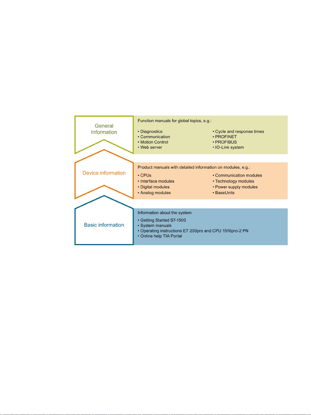
The documentation for the SIMATIC S7-1500 automation system, for CPU 1516pro-2 PN
based on SIMATIC S7-1500, and for the distributed I/O systems SIMATIC ET 200MP,
ET 200SP and ET 200AL is divided into three areas.
This division allows you easier access to the specific information you require.
System manuals and Getting Started manuals describe in detail the configuration,
installation, wiring and commissioning of the SIMATIC S7-1500, ET 200MP, ET 200SP and
ET 200AL systems; use the corresponding operating instructions for CPU 1516pro-2 PN.
The STEP 7 online help supports you in configuration and programming.
Product manuals contain a compact description of the module-specific information, such as
properties, terminal diagrams, characteristics and technical specifications.
PROFINET with STEP 7 V14
Function Manual, 09/2016, A5E03444486-AG
11
Page 12

Documentation guide
General information
Manual Collections
"mySupport"
"mySupport" - Documentation
The function manuals contain detailed descriptions on general topics such as diagnostics,
communication, Motion Control, Web server, OPC UA.
You can download the documentation free of charge from the Internet
http://w3.siemens.com/mcms/industrial-automation-systems-simatic/en/manual-
(
overview/Pages/Default.aspx).
Changes and additions to the manuals are documented in product information sheets.
You will find the product information on the Internet:
● S7-1500/ET 200MP (https://support.industry.siemens.com/cs/us/en/view/68052815
● ET 200SP (https://support.industry.siemens.com/cs/us/en/view/73021864)
● ET 200AL (https://support.industry.siemens.com/cs/us/en/view/99494757)
The Manual Collections contain the complete documentation of the systems put together in
one file.
You will find the Manual Collections on the Internet:
● S7-1500/ET 200MP (https://support.industry.siemens.com/cs/ww/en/view/86140384
● ET 200SP (https://support.industry.siemens.com/cs/ww/en/view/84133942)
● ET 200AL (https://support.industry.siemens.com/cs/ww/en/view/95242965)
With "mySupport", your personal workspace, you make the best out of your Industry Online
Support.
In "mySupport", you can save filters, favorites and tags, request CAx data and compile your
personal library in the Documentation area. In addition, your data is already filled out in
support requests and you can get an overview of your current requests at any time.
)
)
You must register once to use the full functionality of "mySupport".
You can find "mySupport" on the Internet (https://support.industry.siemens.com/My/ww/en
).
In the Documentation area in "mySupport" you can combine entire manuals or only parts of
these to your own manual.
You can export the manual as PDF file or in a format that can be edited later.
You can find "mySupport" - Documentation on the Internet
(http://support.industry.siemens.com/My/ww/en/documentation
PROFINET with STEP 7 V14
12 Function Manual, 09/2016, A5E03444486-AG
).
Page 13

Documentation guide
"mySupport" - CAx data
Application examples
TIA Selection Tool
In the CAx data area in "mySupport", you can access the current product data for your CAx
or CAe system.
You configure your own download package with a few clicks.
In doing so you can select:
● Product images, 2D dimension drawings, 3D models, internal circuit diagrams, EPLAN
macro files
● Manuals, characteristics, operating manuals, certificates
● Product master data
You can find "mySupport" - CAx data on the Internet
(http://support.industry.siemens.com/my/ww/en/CAxOnline
).
The application examples support you with various tools and examples for solving your
automation tasks. Solutions are shown in interplay with multiple components in the system separated from the focus on individual products.
You will find the application examples on the Internet
(https://support.industry.siemens.com/sc/ww/en/sc/2054
With the TIA Selection Tool, you can select, configure and order devices for Totally
Integrated Automation (TIA).
This tool is the successor of the SIMATIC Selection Tool and combines the known
configurators for automation technology into one tool.
With the TIA Selection Tool, you can generate a complete order list from your product
selection or product configuration.
You can find the TIA Selection Tool on the Internet
(http://w3.siemens.com/mcms/topics/en/simatic/tia-selection-tool
).
).
PROFINET with STEP 7 V14
Function Manual, 09/2016, A5E03444486-AG
13
Page 14

Documentation guide
SIMATIC Automation Tool
PRONETA
You can use the SIMATIC Automation Tool to run commissioning and maintenance activities
simultaneously on different SIMATIC S7 stations as a bulk operation, independently of the
TIA Portal.
The SIMATIC automation tool provides a variety of functions:
● Scanning of a PROFINET/Ethernet plant network and identification of all connected CPUs
● Address assignment (IP, subnet, gateway) and station name (PROFINET device) to a
CPU
● Transfer of the date and programming device/PC time converted to UTC time to the
module
● Program download to CPU
● Operating mode switchover RUN/STOP
● CPU localization by means of LED flashing
● Reading out CPU error information
● Reading of CPU diagnostic buffer
● Reset to factory settings
● Updating the firmware of the CPU and connected modules
You can find the SIMATIC Automation Tool on the Internet
(https://support.industry.siemens.com/cs/ww/en/view/98161300
With SIEMENS PRONETA (PROFINET network analysis), you analyze the plant network
during commissioning. PRONETA features two core functions:
● The topology overview independently scans PROFINET and all connected components.
● The IO check is a fast test of the wiring and the module configuration of a plant.
You can find SIEMENS PRONETA on the Internet
(https://support.industry.siemens.com/cs/ww/en/view/67460624
).
).
PROFINET with STEP 7 V14
14 Function Manual, 09/2016, A5E03444486-AG
Page 15

2
2.1
Introduction to PROFINET
What is PROFINET IO?
Objectives of PROFINET
Within the framework of Totally Integrated Automation (TIA), PROFINET IO is the logical
further development of:
● PROFIBUS DP, the established fieldbus and
● Industrial Ethernet
PROFINET IO is based on 20 years of experience with the successful PROFIBUS DP and
combines the normal user operations with the simultaneous use of innovative concepts of
Ethernet technology. This ensures the integration of PROFIBUS DP into the PROFINET
world.
PROFINET IO as the Ethernet-based automation standard of PROFIBUS/PROFINET
International defines a cross-vendor communication, automation, and engineering model.
The objectives of PROFINET:
● Industrial networking, based on Industrial Ethernet (open Ethernet standard)
● Compatibility of Industrial Ethernet and standard Ethernet components
● High robustness due to Industrial Ethernet devices. Industrial Ethernet devices are suited
to the industrial environment (temperature, noise immunity, etc.).
● Use of IT standards such as TCP/IP, http.
● Real-time capability
● Seamless integration of other fieldbus systems
PROFINET with STEP 7 V14
Function Manual, 09/2016, A5E03444486-AG
15
Page 16
Description
Implementation of PROFINET in SIMATIC
PROFINET IO
STEP 7
2.1 Introduction to PROFINET
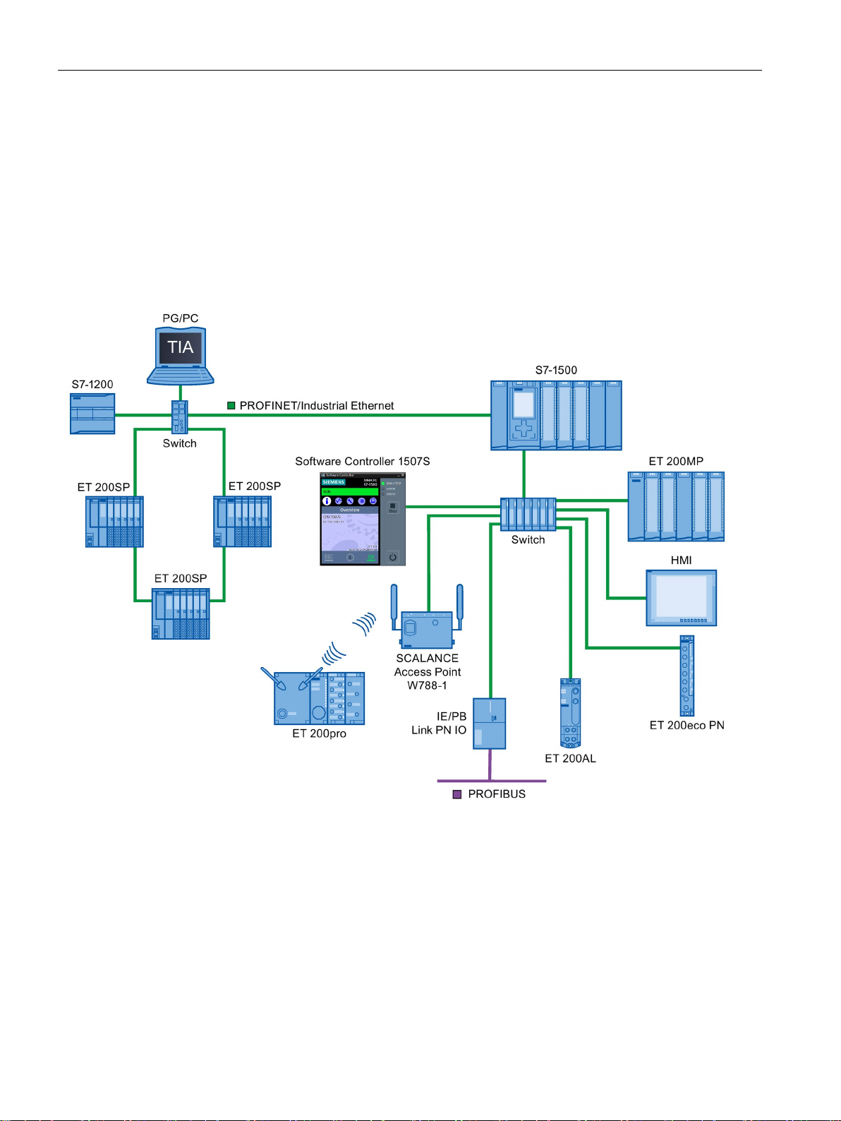
PROFINET is implemented in SIMATIC as follows:
● We have implemented communication between field devices in SIMATIC with
● Installation technology and network components are available as SIMATIC NET products.
● Ethernet standard protocol and procedures (e.g., SNMP = Simple Network Management
Protocol for network parameter assignment and diagnostics) are used for remote
maintenance and network diagnostics.
.
Figure 2-1 PROFINET overview configuration
The STEP 7 engineering tool supports you in setting up and configuring an automation
solution. STEP 7 provides a uniform application view over all bus systems.
PROFINET with STEP 7 V14
16 Function Manual, 09/2016, A5E03444486-AG
Page 17

Description
Documentation from PROFIBUS & PROFINET International on the Internet
Overview of the most important documents and links
2.1.1
PROFINET terms
Definition: Devices in the PROFINET environment
2.1 Introduction to PROFINET
You will find numerous documents on the topic of PROFINET at the Internet address
(http://www.profibus.com
organization, which is also responsible for PROFINET.
Additional information can be found on the Internet (http://www.siemens.com/profinet).
) of the "PROFIBUS & PROFINET International" PROFIBUS user
A compilation of the most important PROFINET application examples, FAQs and other
contributions in the Industry Online Support is available in this FAQ
).
(https://support.industry.siemens.com/cs/ww/en/view/108165711
In the PROFINET environment, "device" is the generic term for:
● Automation systems (PLC, PC, for example)
● Distributed I/O systems
● Field devices (for example, hydraulic devices, pneumatic devices)
● Active network components (for example, switches, routers)
● Gateways to PROFIBUS, AS interface or other fieldbus systems
PROFINET with STEP 7 V14
Function Manual, 09/2016, A5E03444486-AG
17
Page 18
Description
PROFINET IO devices
Number
PROFINET
Explanation
①
PROFINET IO System
②
and output signals with field devices.
③
(PROFINET IO supervisor)
diagnostics
④
PROFINET/Industrial Ethernet
Network infrastructure
⑤
HMI (Human Machine Interface)
Device for operating and monitoring functions.
⑥
ed PROFINET IO functionality)
⑦
I-device
Intelligent IO device
2.1 Introduction to PROFINET
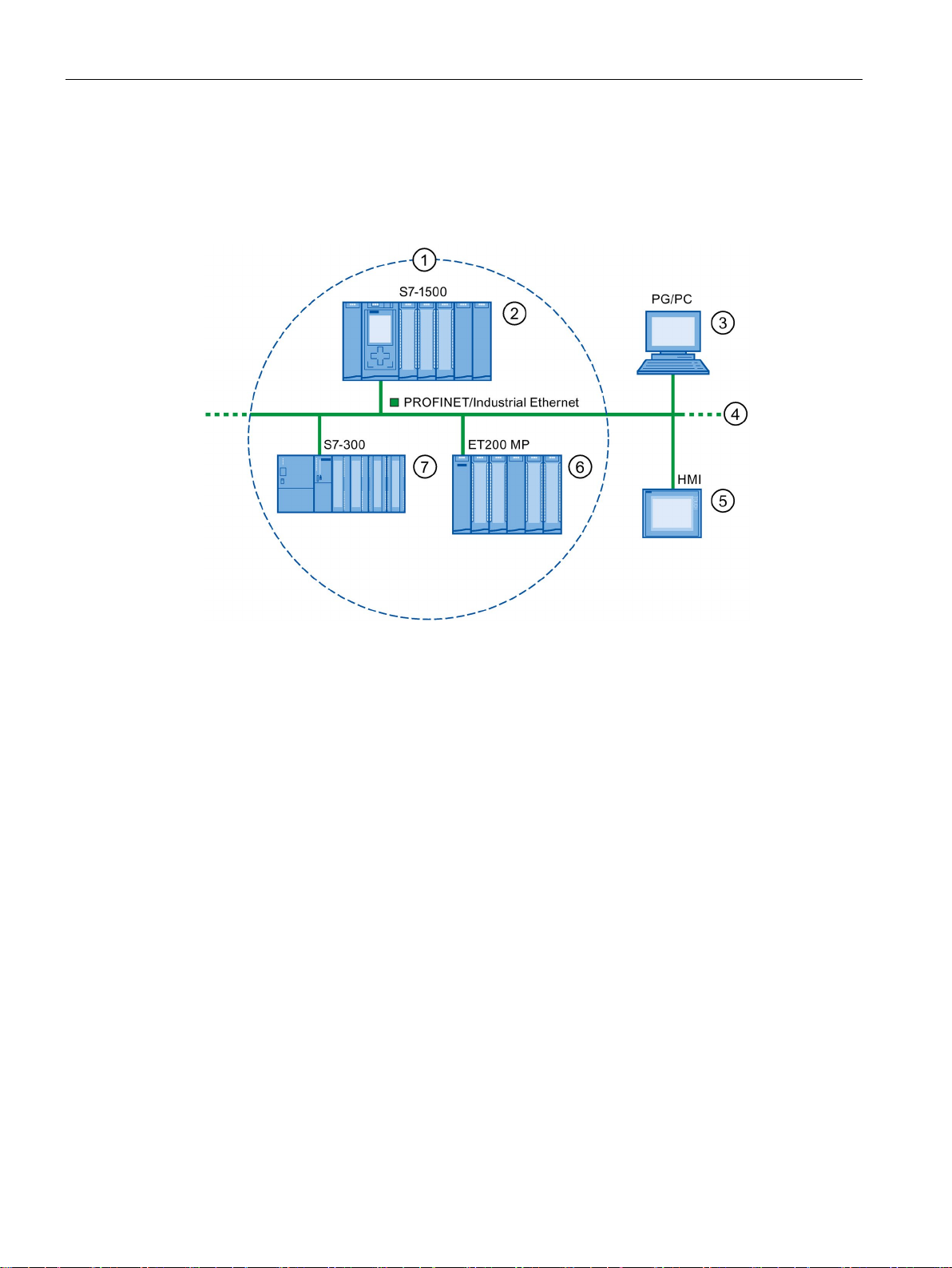
The following graphic shows the general names used for the most important devices in
PROFINET. In the table below the graphic you can find the names of the individual
components in the PROFINET IO context.
IO controller Device used to address the connected IO devices.
This means that: The IO controller exchanges input
Programming device / PC
IO device A distributed field device that is assigned to one of
Figure 2-2 PROFINET devices
PG/PC/HMI device used for commissioning and for
the IO controllers (e.g., Distributed IO, valve terminals, frequency converters, switches with integrat-
PROFINET with STEP 7 V14
18 Function Manual, 09/2016, A5E03444486-AG
Page 19
Description
IO communication via PROFINET IO
A
IO controller - IO controller communication via PN/PN coupler
B
IO controller - I-device communication
C
IO controller - IO-device communication
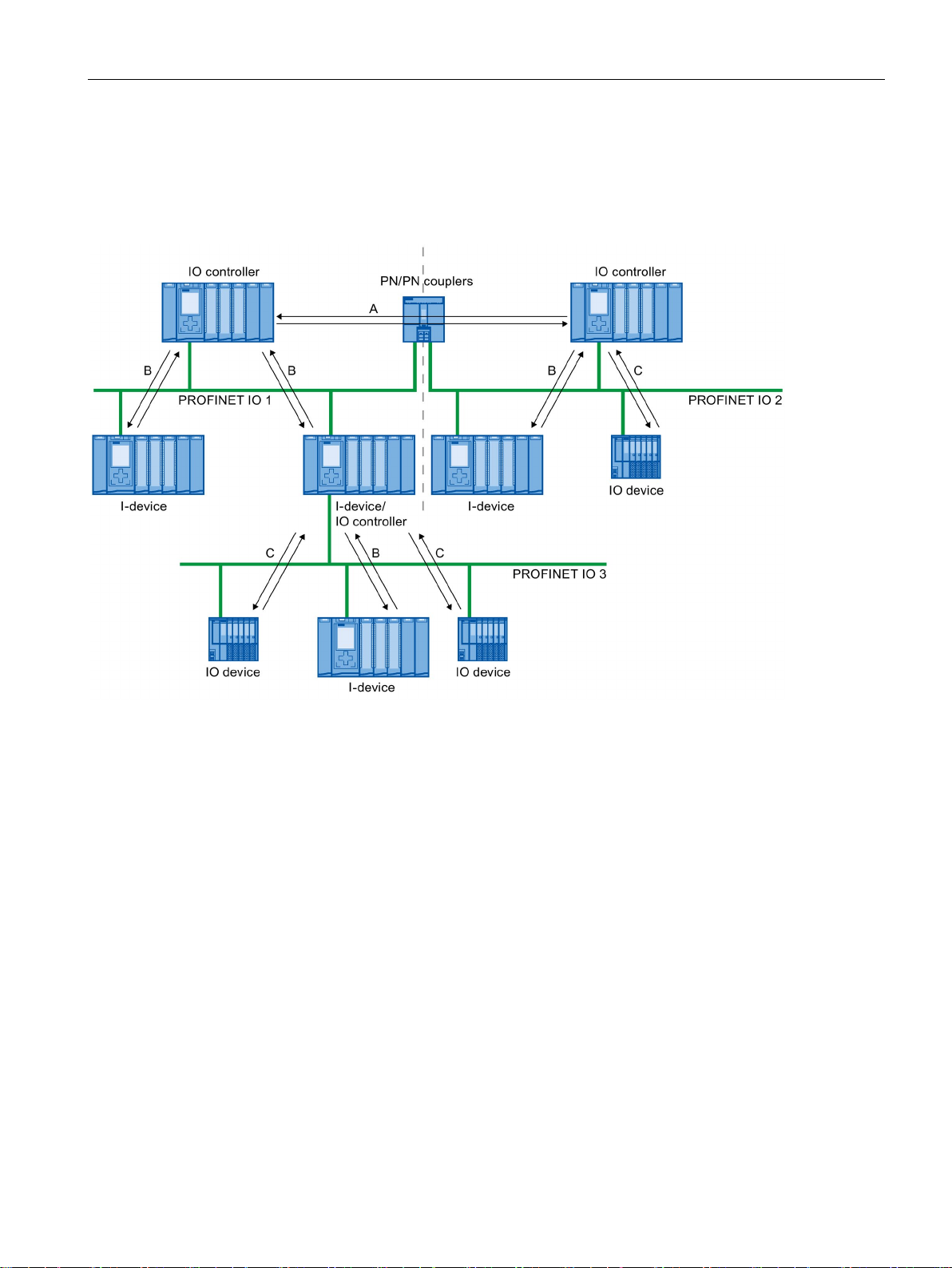
2.1 Introduction to PROFINET
The inputs and outputs of distributed I/O devices are read and written by means of
PROFINET IO using what is referred to as IO communication. The following figure provides
an overview of IO communication by means of PROFINET IO.
Figure 2-3 IO communication via PROFINET IO
PROFINET with STEP 7 V14
Function Manual, 09/2016, A5E03444486-AG
19
Page 20

Description
IO communication via PROFINET IO
Communication between ...
Explanation
receives data from these devices.
A fixed quantity of data is transferred cyclically between the user programs in CPUs of IO
via direct access.
A fixed quantity of data is cyclically transferred between the user programs in CPUs of IO
via direct access.
See also
2.1.2
Basic terminology of communication
PROFINET communication
2.1 Introduction to PROFINET
Table 2- 1 IO communication via PROFINET IO
IO controllers and IO devices The IO controller sends data cyclically to the IO devices of its PROFINET IO system and
IO controller and I-device
controllers and I-devices.
The IO controller does not access the I/O module of the I-device, but instead accesses
configured address ranges, i.e. transfer ranges, which may be located inside our outside
the process image of the CPU of the I-device. If parts of the process image are used as
transfer ranges, it is not permitted to use these for real I/O modules.
Data transfer takes place using load- and transfer operations via the process image or
IO controller and IO controller
controllers. A PN/PN coupler is required as additional hardware.
The IO controllers mutually access configured address ranges, i.e. transfer ranges,
which may be located inside or outside the process image of the CPU. If parts of the
process image are used as transfer ranges, it is not permitted to use these for real I/O
modules.
Data transfer takes place using load- and transfer operations via the process image or
Network security (Page 36)
Functions (Page 93)
Communication (http://support.automation.siemens.com/WW/view/en/59192925
PROFINET communication takes place via Industrial Ethernet. The following transmission
types are supported:
● Acyclic transmission of engineering and diagnostics data and interrupts
● Cyclic transmission of user data
The PROFINET-IO communication takes place in real-time.
For additional information on the real-time communication, refer to chapter Real-time
communication (Page 157).
)
PROFINET with STEP 7 V14
20 Function Manual, 09/2016, A5E03444486-AG
Page 21
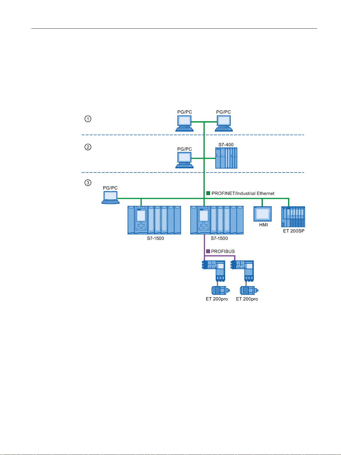
Description
Transparent data access
①
Management level
②
Control level
③
Production level
2.1 Introduction to PROFINET
Access to process data from different levels of the factory is supported by PROFINET
communication. By using Industrial Ethernet, standard mechanisms of communication and
information technology such as OPC/XML can now be used along with standard protocols
such as UDP/TCP/IP and HTTP in automation engineering. This allows transparent access
from company management level directly to the data from the automation systems at the
control level and production level.
PROFINET with STEP 7 V14
Function Manual, 09/2016, A5E03444486-AG
Figure 2-4 Access to process data
21
Page 22

Description
Update time
Watchdog time
Send clock
Relationship between the update time and send clock
Send clock
Update time
Reduction ratios
250 μs
250 μs to 128 ms
1,2, ..., 512
1 ms
1 ms to 512 ms
1,2, ..., 512
2 ms
2 ms to 512 ms
1,2, ..., 256
4 ms
4 ms to 512 ms
1,2, ..., 128
Additional information
2.1 Introduction to PROFINET
The update time is a time interval. IO controller and IO device/I-device exchange IO data
cyclically in the IO system within this time interval. The update time can be configured
separately for each IO device and determines the interval at which output data is sent from
the IO controller to the IO device (output module/submodule) as well as input data from the
IO device to the IO controller (input module/submodule).
STEP 7 calculates the update time automatically in the default setting for each IO device of
the PROFINET IO system, taking into account the volume of data to be exchanged as well
as the set send clock.
For additional information on the update time, refer to section Real-time communication
(Page 157).
The watchdog time is the time interval that an IO controller or IO device permits, without
receiving IO data. If the IO device is not supplied by the IO controller with data within the
watchdog time, the device detects the missing frames and outputs substitute values. This is
reported in the IO controller as a station failure.
In STEP 7, the watchdog time is made up from an integral multiple of the update time and
can be set by the user.
The period of time between two consecutive communication cycles. The send clock is the
shortest possible interval in data exchange.
The calculated update times are reduction ratios (1, 2, 4, 8, ..., 512) of the send clock. The
minimum possible update time thus depends on the minimum send clock of the IO controller
that can be set and the efficiency of the IO controller and IO device. Depending on the send
clock, it can be that only some of the reduction ratios are available (STEP 7 guarantees this
through a pre-selection).
The following tables illustrate the dependency of the update time that can be set on the send
clock, using an example of the CPU 1516-3 PN/DP. The update times satisfy the
requirements of the PROFINET standard IEC 61158.
Table 2- 2 With real-time communication the following applies:
500 μs 500 μs to 256 ms 1,2, ..., 512
PROFINET with STEP 7 V14
22 Function Manual, 09/2016, A5E03444486-AG
For information on real-time communication, refer to the section Real-Time Communication
(RT) (Page 158).
Page 23

Description
2.1.3
PROFINET interface
Overview
Properties
Identification and numbering of the interfaces and ports
Element
Symbol
Interface number
Interface
X
In ascending order starting from number 1
(for each interface)
Ring port
R
Examples of identification
Sample labeling
Interface number
Port number
X2 P1
2
1
X1 P2
1
2
X1 P1 R
1
1 (ring port)
2.1 Introduction to PROFINET
PROFINET devices of the SIMATIC product family have one or more PROFINET interfaces
(Ethernet controller/interface). The PROFINET interfaces have one or more ports (physical
connection options).
In the case of PROFINET interfaces with multiple ports, the devices have an integrated
switch.
PROFINET devices with two ports on one interface allow you to configure the system in a
line or ring topology. PROFINET devices with three or more ports on one interface are also
ideal for setting up tree topologies.
Properties and rules for naming the PROFINET interface and its representation in STEP 7
are explained in the following.
Every PROFINET device on the network is uniquely identified via its PROFINET interface.
For this purpose, each PROFINET interface has:
● A MAC address (factory default)
● An IP address
● A PROFINET device name
Interfaces and ports for all modules and devices in the PROFINET system are identified with
the following characters:
Table 2- 3 Identification for interfaces and ports of PROFINET devices
Port P In ascending order starting from number 1
Three examples illustrate the rules for identifying PROFINET interfaces:
Table 2- 4 Examples for identifying PROFINET interfaces
PROFINET with STEP 7 V14
Function Manual, 09/2016, A5E03444486-AG
23
Page 24
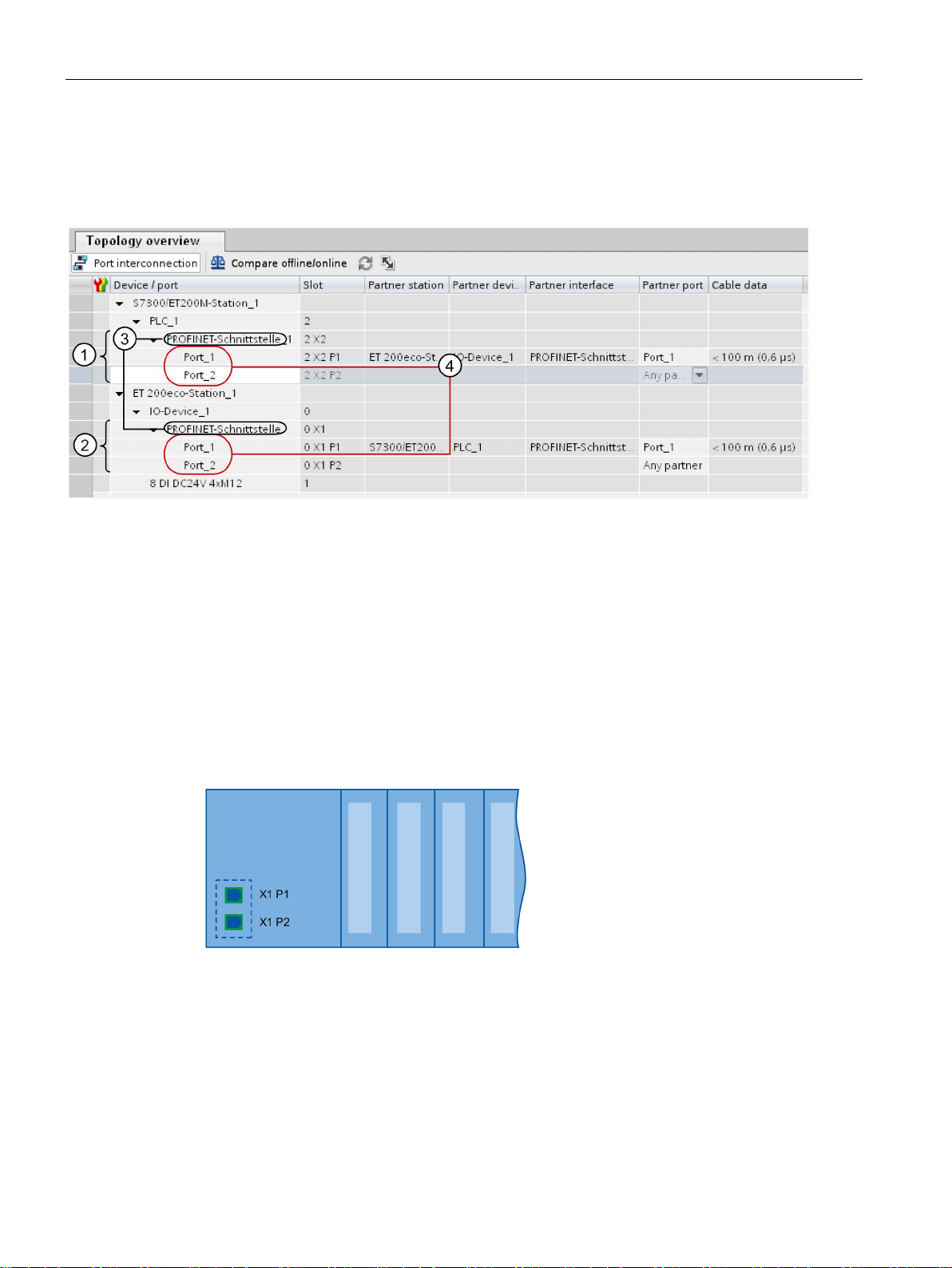
Description
Representation of PROFINET Interfaces in the Topology Overview in STEP 7
Number
Description
①
PROFINET interface of an IO controller in STEP 7
②
PROFINET interface of an IO device in STEP 7
③
These lines represent the PROFINET interface.
④
These lines represent the "ports" of a PROFINET interface.
Schematic Representation of a PROFINET Interface with Integrated Switch
2.1 Introduction to PROFINET
You can find the PROFINET interface in the topology overview in STEP 7. The PROFINET
interface for an IO controller and an IO device is represented as follows in STEP 7:
Figure 2-5 Representation of the PROFINET interfaces in STEP 7
The following schematic diagram shows the PROFINET interface with integrated switch and
its ports for all PROFINETdevices.
Figure 2-6 PROFINET interface with integrated switch
PROFINET with STEP 7 V14
24 Function Manual, 09/2016, A5E03444486-AG
Page 25

Description
Functional differences of the PROFINET interfaces
PROFINET interface (X1)
PROFINET interface (X2)
2 ports with PROFINET IO functionality:
1 port with PROFINET IO functionality:
PG communication
HMI communication
S7 communication
Time-of-day synchronization
Web server
Open communication
OPC UA server
IO controller
I-device
RT
IRT
-
Isochronous mode
-
Media redundancy
-
Prioritized startup
-
Additional Information on the Functionality of PROFINET interfaces
2.1 Introduction to PROFINET
PROFINET interfaces can provide different functions. PROFINET interface functions include
identification, configuration, diagnostics and communication services (e.g., open
communication). PROFINET interfaces that provide PROFINET IO functions and network
security functions are also available.
The following table illustrates the differences using the example of the CPU 1516-3 PN/DP
(as of firmware version V2.0), which features two PROFINET interfaces with different
functionality.
Table 2- 5 Differences between the PROFINET interfaces of the CPU 1516-3 PN/DP (as of firm-
ware version V2.0)
Identification, configuration and diagnostics
You can find information on the number and functionality of the interfaces of a PROFINET
device in the documentation for the specificPROFINET device.
PROFINET communication services are described in the Communication function manual.
In the Network security section you can find components that are used to protect networks
against hazards.
The Functions section describes the PROFINET IO functions.
PROFINET with STEP 7 V14
Function Manual, 09/2016, A5E03444486-AG
25
Page 26
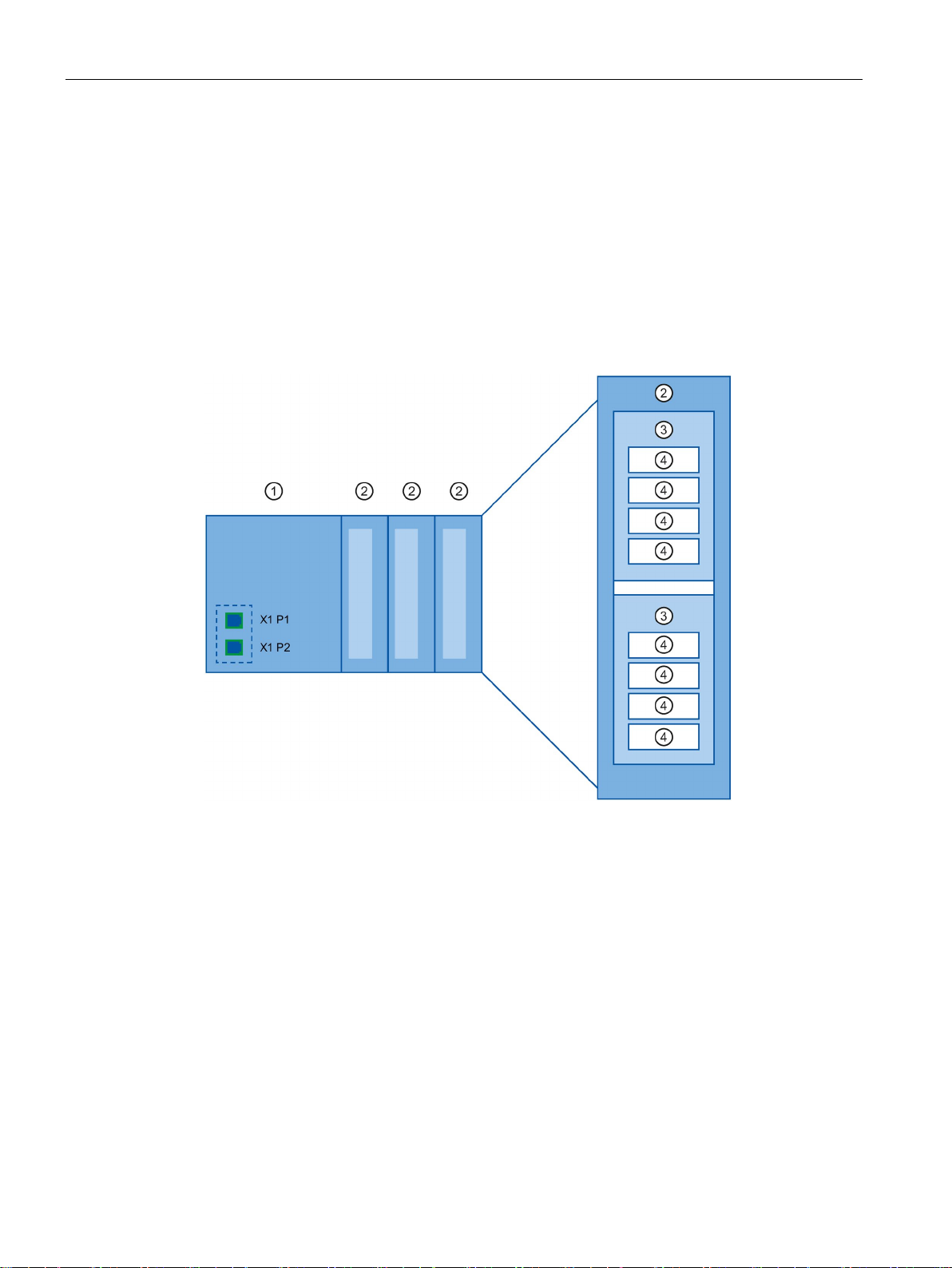
Description
2.1.4
Implementation of the PROFINET device model in SIMATIC
Slots and modules
Number
Description
①
Slot with bus interface
②
Slot with module
③
Subslot with submodule
④
Channel
2.1 Introduction to PROFINET
A PROFINET device can have a modular and compact structure. A modular PROFINET
device consists of slots into which the modules are inserted. The modules have channels
which are used to read and output process signals. A compact device has the same design
and can include modules, however, it cannot be physically expanded, which means that no
modules can be inserted.
This is illustrated by the following graphic.
PROFINET with STEP 7 V14
26 Function Manual, 09/2016, A5E03444486-AG
Figure 2-7 Configuration of a PROFINET device
A module can contain multiple submodules.
Page 27

Description
Representation of PROFINET Device Model in the Device View of STEP 7
2.2
Setting up PROFINET
Contents of this chapter
Physical connections of industrial networks
2.2 Setting up PROFINET
The following figure shows the representation of the PROFINET device model in the device
view of STEP 7, based on the example of a distributed I/O system ET 200MP:
Figure 2-8 PROFINET device model in the device view of STEP 7
The following chapter provides background information on building your communication
network.
● Overview of the most important passive network components: These are network
components that forward a signal without the possibility of actively influencing it, for
example, cables, connectors, etc.
● Overview of the most important active network components: These are network
components that actively affect a signal, for example switches, routers, etc.
● Overview of the most common network structures (topologies).
PROFINET devices can be networked in industrial systems in two different physical ways:
● Connected line
– By means of electrical pulses via copper cables
– By means of optical pulses via fiber-optic cables
● Wireless via wireless network using electromagnetic waves
PROFINET with STEP 7 V14
Function Manual, 09/2016, A5E03444486-AG
27
Page 28

Description
Fast Ethernet
Industrial Ethernet
2.2.1
Active Network Components
Introduction
Switched Ethernet
Switches
2.2 Setting up PROFINET
PROFINET devices and cabling technology in SIMATIC are suited for industrial use, as they
are based on Fast Ethernet and Industrial Ethernet.
●
You can use Fast Ethernet to transfer data at a speed of 100 Mbps. This transmission
technology uses the 100 Base-T standard for this.
●
Structure of Ethernet in industrial environment.
The biggest difference from standard Ethernet is the mechanical current carrying capacity
and noise immunity of the individual components.
The following active network components are available for PROFINET:
● Switch
● Router
PROFINET IO is based on switched Ethernet with full-duplex operation and a bandwidth of
100 Mbps. In this way, the network can be used much more efficiently through the
simultaneous data transfer of several devices. The PROFINET IO frames are processed with
high priority.
Switches are network components used to connect several terminal devices or network
segments in a local network (LAN).
For the communication of a device with several other devices on PROFINET, the device is
connected to the port of a switch. Other communication devices (including switches) can
then be connected to the other ports of the switch. The connection between a
communication device and the switch is a point-to-point connection.
A switch has the task of receiving and distributing frames. The switch "learns" the Ethernet
address(es) of a connected PROFINET device or additional switches and only forwards
those frames that are intended for the connected PROFINET device or the connected
switch.
PROFINET with STEP 7 V14
28 Function Manual, 09/2016, A5E03444486-AG
Page 29

Description
Switch variants
Selection Guide for Switches
Switches of the SCALANCE product family
2.2 Setting up PROFINET
Switches are available in two models:
● Integrated into a PROFINET device
For PROFINET devices with multiple ports (two or more), we are dealing with devices
with an integrated switch (for example, CPU 1516-3 PN/DP).
● As autonomous device (for example, switches of the SCALANCE product family)
To use PROFINET with the RT class "RT", you can use any switch of "PROFINET
Conformance Class A" or higher. All switches of the SCALANCE product family meet these
requirements.
If you want to use PROFINET functions that provide an additional value, such as topology
recognition, diagnostics, device exchange without exchangeable medium/programming
device, you have to use a switch of the "PROFINET Conformance Class B" or higher.
To use PROFINET with the RT class "IRT", you must use a switch of "PROFINET
Conformance Class C". With switches of the SCALANCE product family, watch out for the
catalog feature "IRT PROFINET IO switch".
To select appropriate switches, we recommend the SIMATIC NET Selection Tool on the
Internet (http://support.automation.siemens.com/WW/view/en/39134641
Use the switches of the SCALANCE product family if you want to use the full scope of
PROFINET. They are optimized for use in PROFINET IO.
In the SCALANCE X device family, you will find switches with electrical and optical ports and
with a combination of both variants. SCALANCE X202-2IRT, for example, has two electrical
ports and two optical ports and supports IRT communication.
Beginning with the SCALANCE X200, you can configure, diagnose and address switches of
the SCALANCE X device series as PROFINET IO devices using STEP 7.
).
PROFINET with STEP 7 V14
Function Manual, 09/2016, A5E03444486-AG
29
Page 30

Description
Router
Note
If devices need to communicate beyond the limits of a network, you must configure
router so that it allows this communication to take place.
2.2.2
Cabling technology
Cables for PROFINET
Simple method for the prefabrication of twisted pair cables
Note
A maximum of four plug
2.2 Setting up PROFINET
A router connects separated network segments with each other (e.g. management level and
control level). The volume of data volume must be coordinated with the services of the
respective network segment. A router also separates two networks and acts as a mediator
between both networks. It thus reduces the network load. Routing functionality is provided in
the SCALANCE X device family, with SCALANCE X300 or higher.
Communication devices on different sides of a router can only communicate with one
another if you have explicitly enabled communication between them via the router.
If you want to access manufacturing data directly from SAP, for example, use a router to
connect your Industrial Ethernet in the factory with the Ethernet in your office.
the
Information on routing with STEP 7 is available in the function manual Communication
(http://support.automation.siemens.com/WW/view/en/59192925
).
Electrical and optical cables are available for PROFINET. The type of cable depends on the
data transfer requirements and on the ambient conditions.
When you set up your PROFINET system, you can cut the twisted-pair cable to the required
length on site, strip it with the
Ethernet Fast Connect RJ45 plugs
stripping tool
using the cut-and-clamp method. For more information on
installation, refer to the installation instructions in the "SIMATIC NET Industrial Ethernet
Network Manual" (http://support.automation.siemens.com/WW/view/en/8763736
-in pairs are allowed between two switches per Ethernet path.
(for Industrial Ethernet), and fit the
Industrial
).
PROFINET with STEP 7 V14
30 Function Manual, 09/2016, A5E03444486-AG
Page 31

Description
Simple method for the prefabrication of fiber-optic cables
Simple method for the prefabrication of POF and PCF cables
Overview of transmission media with PROFINET
Physical
properties
Connection
methods
Cable type / transmission medium
standard
Transmission rate /
mode
Max. segment length
devices)
Advantages
Electrical
IEEE 802.3
Optical
ISO/IEC 60793-2
ISO/IEC 60793-2
2.2 Setting up PROFINET
The FastConnect FO cabling system is available for the easy, fast and error-free
prefabrication of fiber-optic cables. The glass-fiber optic cable consists of:
● FC FO Termination Kit for SC and BFOC plug (cleave tool, Kevlar scissors, buffer grip,
fiber remains container)
● FC BFOC Plug
● FC SC Duplex plug
● FO FC Standard cable
● FO FC Trailing cable
The following special tools provide an easy and safe way to prefabricate POF / PCF cables
and fit the SC RJ POF plugs:
● POF cable
Prefabrication case IE Termination Kit SC RJ POF plug
● PCF cable
Prefabrication case IE Termination Kit SC RJ PCF plug
The following table summarizes the technical specifications of a PROFINET interface with
integrated switch or an external switch, and possible transmission media.
Table 2- 6 Transmission media with PROFINET
RJ45 connector
ISO 60603-7
SCRJ 45
ISO/IEC
61754-24
100Base-TX
2x2 twisted, symmetrical and
shielded copper cable, CAT 5
transmission requirement
100Base-FX
POF fiber-optic cable (Polymer
Optical Fiber, POF)
980/1000 µm (core diameter /
external diameter)
Plastic-cladded glass fiber (Polymer Cladded Fiber, PCF)
200/230 µm (core diameter / external diameter)
100 Mbps, full
duplex
100 Mbps, full
duplex
100 Mbps, full
duplex
(between two
100 m Simple and cheap
cable connection
50 m Use when there
are large differences in potential
Insensitive towards
electromagnetic
radiation
100 m
Low line attenuation
Considerably longer segments possi-
1
ble
PROFINET with STEP 7 V14
Function Manual, 09/2016, A5E03444486-AG
31
Page 32

Description
Physical
properties
Connection
methods
Cable type / transmission medium
standard
Transmission rate /
mode
Max. segment length
devices)
Advantages
ISO/IEC 60793-2
ISO/IEC 9314-4
Electromagnetic
waves
access devices
1
Applies for fiber-optic cables only
See also
2.2 Setting up PROFINET
(between two
BFOC (Bayonet
Fiber Optic
Connector) and
SC (Subscriber
Connector)
ISO/IEC 60874
- IEEE 802.11 x Depends on the
PROFINET interface (Page 23)
Assembly Instructions for SIMATIC NET Industrial Ethernet
(http://support.automation.siemens.com/WW/view/en/27069465
PROFINET Installation Guideline (http://www.profibus.com/nc/download/installation-
guide/downloads/profinet-installation-guide/display/)
Monomode glass fiber optic cable
10/125 µm (core diameter / exter-
nal diameter)
Multimode glass fiber optic cable
50/125 µm and 62.5/125 µm (core
diameter / external diameter)
100 Mbps, full
duplex
100 Mbps, full
duplex
extension used (a,
g, h, etc.)
26 km
3000 m
100 m Greater mobility
Cost-effective
networking to remote, difficult to
)
PROFINET with STEP 7 V14
32 Function Manual, 09/2016, A5E03444486-AG
Page 33

Description
2.2.3
Wireless design
2.2.3.1
Basics
What is Industrial Wireless LAN?
Objectives and advantages of Industrial Wireless LAN
Application examples
2.2 Setting up PROFINET
In addition to data communication in accordance with the IEEE 802.11 standard, the
SIMATIC NET Industrial Wireless LAN provides a number of enhancements which offer
significant benefits for industrial customers. IWLAN is particularly suitable for demanding
industrial applications that require reliable wireless communication. This is supported by the
following properties:
● Automatic roaming when the connection to Industrial Ethernet is interrupted (Forced
Roaming)
● Cost savings generated by using a single wireless network for reliable operation of a
process with both process-critical data (alarm message, for example) and non-critical
communication (service and diagnostics, for example)
● Cost-effective connection to devices in remote environments that are difficult to access
● Predictable data traffic (deterministic) and defined response times
● Cyclical monitoring of the wireless link (link check)
Wireless data transmission achieves the following objectives:
● Seamless integration of PROFINET devices into the existing bus system via the wireless
interface
● Mobile use of PROFINET devices for different production-linked tasks
● Flexible configuration of the system components for fast development in accordance with
customer requirements
● Maintenance costs are minimized by savings in cables
● Communication with mobile subscribers (mobile controllers and devices, for example),
conveyor lines, production belts, translation stages , and rotating machines
● Wireless coupling of communication segments for fast commissioning or cost-effective
networking where routing of wires is extremely expensive (e.g. public streets, railroad
lines)
● Stacker trucks, automated guided vehicle systems and suspended monorail systems
PROFINET with STEP 7 V14
Function Manual, 09/2016, A5E03444486-AG
33
Page 34
Description
Data transmission rate
2.2 Setting up PROFINET
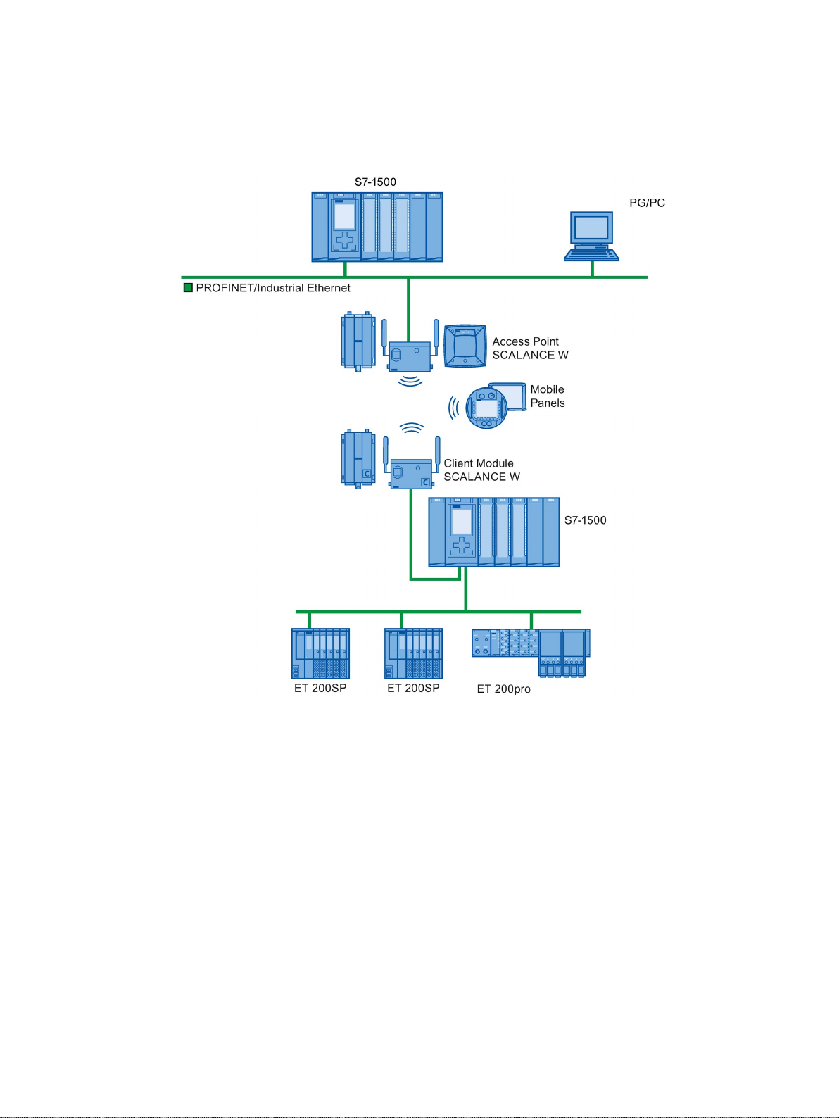
The following graphic illustrates the many possible applications and configurations for
SIMATIC device family wireless networks.
Figure 2-9 Application example for the use of Industrial Wireless LAN
In Industrial Wireless LAN, gross data transmission rates of 11 Mbps or 54 Mbps without full
duplex are permitted.
PROFINET with STEP 7 V14
34 Function Manual, 09/2016, A5E03444486-AG
Page 35
Description
Range
Note
Range
The range can be consi
used, the data rate, and the antennas on the send and receive sides.
2.2.3.2
Tips on assembly
Wireless networks, SCALANCE device family
Update time in STEP 7
2.2 Setting up PROFINET
With SCALANCE W (access points), wireless networks can be set up indoors and outdoors.
Multiple access points can be installed to create large wireless networks in which mobile
subscribers are transferred seamlessly from one access point to another (roaming).
As an alternative to a wireless network, point-to-point connections of Industrial Ethernet
segments can also be set up over large distances (several hundred meters). In this case, the
range and characteristics of the RF field are determined by the antennas used.
derably less, depending on spatial factors, the wireless standard
With PROFINET, you can also set up wireless networks with Industrial Wireless Local Area
Network (IWLAN) technology. We recommend implementing the SCALANCE W device line
for this.
If you set up PROFINET with Industrial Wireless LAN, you may have to increase the update
time for the wireless devices. The IWLAN interface provides lower performance than the
wired data network: Several communication stations have to share the limited transmission
bandwidth. For wired solutions, 100 Mbps is available for each communication device.
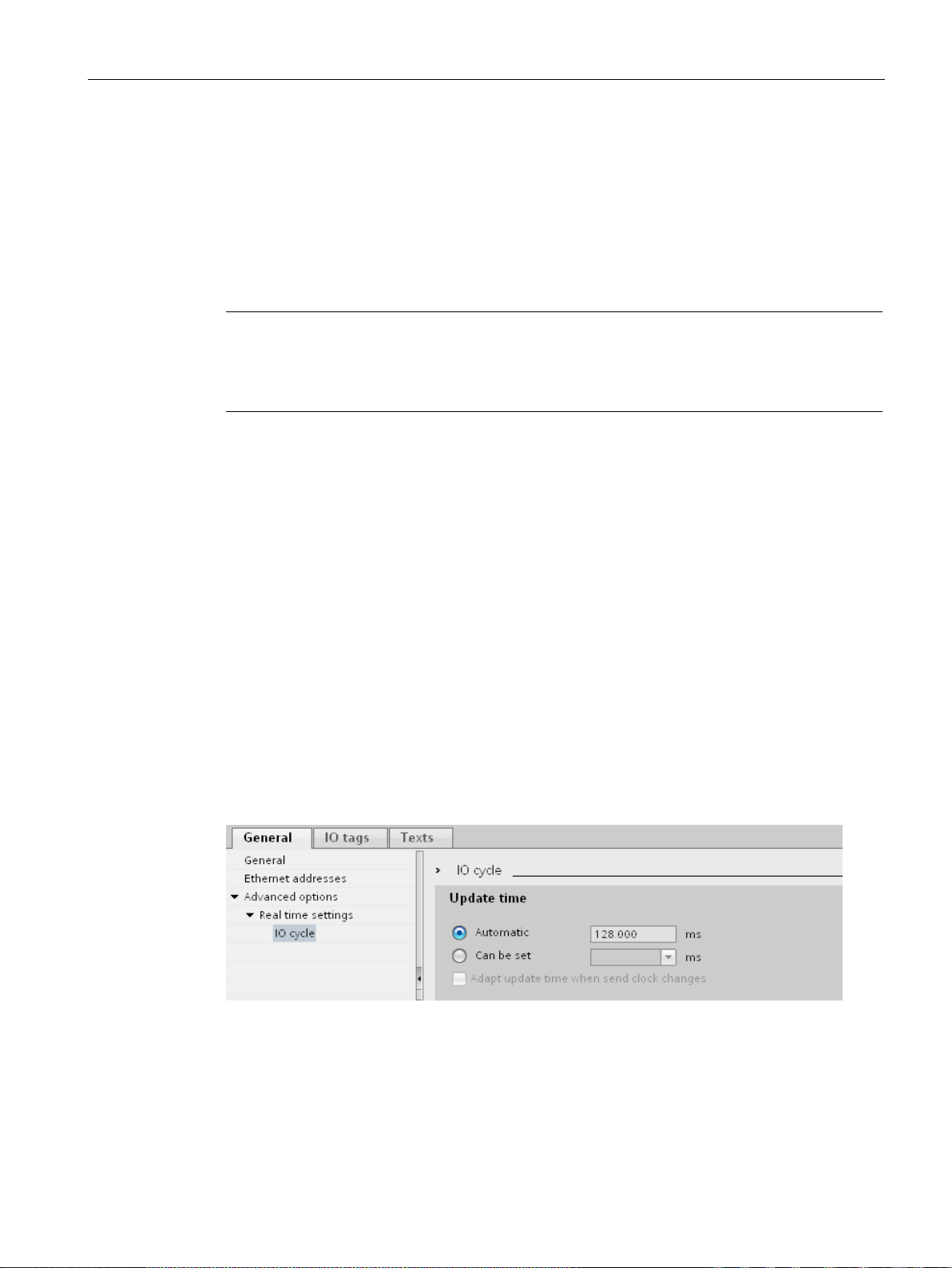
The Update time parameter can be found in the "Realtime settings" section in the Inspector
window of IO devices in STEP 7.
Figure 2-10 Update time in STEP 7
PROFINET with STEP 7 V14
Function Manual, 09/2016, A5E03444486-AG
35
Page 36

Description
Additional information
2.2.4
Network security
2.2.4.1
Basics
Introduction
Requirements
2.2 Setting up PROFINET
More information about SCALANCE W Industrial Wireless LAN components can be found in
the manual SIMATIC NET SCALANCE W-700
(http://support.automation.siemens.com/WW/view/en/42784493
More information about wired data transmission can be found in the manual SIMATIC NET
Twisted Pair and Fiber Optic Networks
(http://support.automation.siemens.com/WW/view/en/8763736
More information about wireless data transmission can be found in the manual Basics for
configuring an industrial wireless LAN
(http://support.automation.siemens.com/WW/view/en/9975764
You should also read the PROFINET installation guideline of the PROFIBUS User
Organization on the Internet (
guide/downloads/profinet-installation-guide/display/). Various documents that assist with the
setting up of your PROFINET automation solution are available here:
● PROFINET planning guideline
● PROFINET installation guideline
● PROFINET commissioning guideline
http://www.profibus.com/nc/download/installation-
).
).
).
● Additional documents for setup of PROFINET
The topic of data security and access protection (Security) has become increasingly
important in the industrial environment. The increased networking of entire industrial
systems, vertical integration and networking of levels within a company and new techniques
such as remote maintenance all result in higher requirements for protecting the industrial
plant.
Data security solutions for office environments cannot simply be transferred one-to-one to
industrial applications to protect against manipulation in sensitive systems and production
networks.
Additional security requirements arise from the specific communication requirements in the
industrial environment (real-time communication, for example):
● Protection against interaction between automated cells
● Protection of network segments
● Protection against faulty and unauthorized access
● Scalability of network security
● Must not influence the network structure
PROFINET with STEP 7 V14
36 Function Manual, 09/2016, A5E03444486-AG
Page 37

Description
Definition of security
Threats
2.2 Setting up PROFINET
Generic term for all the measures taken to protect against:
● Loss of confidentiality due to unauthorized access to data
● Loss of integrity due to manipulation of data
● Loss of availability due to destruction of data, for example, through faulty configuration
and denial-of-service attacks
Threats can arise from external and internal manipulation. The loss of data security is not
always caused by intentional actions.
Internal threats can arise due to:
● Technical errors
● Operator errors
● Defective programs
Added to these internal threats there are also external ones. The external threats are not
really any different to the known threats in the office environment:
● Software viruses and worms
● Trojans
● Man-in-the-middle attacks
● Password Phishing
● Denial of Service
PROFINET with STEP 7 V14
Function Manual, 09/2016, A5E03444486-AG
37
Page 38

Description
Protective measures
2.2.4.2
Network components and software
Protection against unauthorized access
Features
2.2 Setting up PROFINET
The most important precautions to prevent manipulation and loss of data security in the
industrial environment are:
● Filtering and control of data traffic by means of firewall
● A virtual private network (VPN) is used to exchange private data on a public network
(Internet, for example).
The most common VPN technology is IPsec. IPsec (Internet Protocol Security) is a
collection of security protocols that are used as the basis for the IP protocol at the
mediation level and allow a secured communication via potentially unsecure IP networks.
● Segmenting in protected automation cells
This concept has the aim of protecting the lower-level network devices by means of
security modules. A group of protected devices forms a protected automation cell.
● Authentication (identification) of the devices
The security modules identify each other over a safe (encrypted) channel using
authentication procedures. It is therefore impossible for unauthorized parties to access a
protected segment.
● Encrypting the data traffic
The confidentiality of data is ensured by encrypting the data traffic. Each security module
is given a VPN certificate which includes the encryption key.
The following solutions may be used to connect industrial networks to the intranet and
Internet to protect against internal and external threats:
● Communication processors, such as the SIMATIC CP 1543-1
● SCALANCE X-300 and SCALANCE S - the data security components of the
SIMATIC NET product family
● SOFTNET security client for use on PCs
Both of these products have a wide variety of features, such as:
● Easy integration of existing networks without configuration, with integrated firewall.
● Segmenting in protected automation cells
● Authentication (identification) of the devices
● Encrypting the data traffic
PROFINET with STEP 7 V14
38 Function Manual, 09/2016, A5E03444486-AG
Page 39
Description
2.2.4.3
Application example
Data security at the office and production levels
2.2 Setting up PROFINET
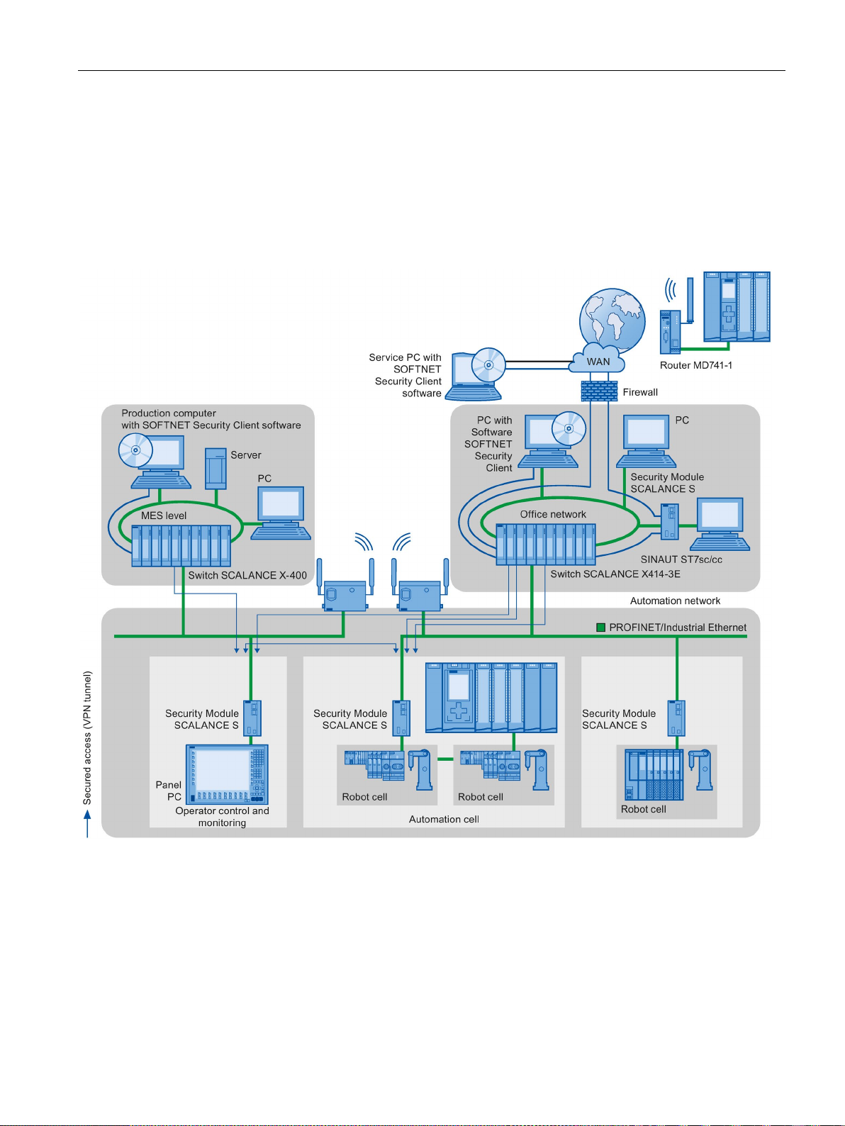
The following graphic contains an application example with protected areas at different levels
of the company created using SCALANCE S and the security client. The protected areas are
highlighted in light gray.
Figure 2-11 Network configuration with the SCALANCE S security module and the SOFTNET security client
PROFINET with STEP 7 V14
Function Manual, 09/2016, A5E03444486-AG
39
Page 40

Description
Additional information
2.2 Setting up PROFINET
Additional information on the configuration of a security standard in PROFINET, is available:
● In the PROFINET security guideline. These guidelines can be found on the homepage of
the PROFIBUS user organization on the Internet (http://www.profinet.com
● In the Industrial Ethernet Security
(http://support.automation.siemens.com/WW/view/en/56577508
● In the SCALANCE S and SOFTNET Security Client
(http://support.automation.siemens.com/WW/view/en/21718449
You can find general information on industrial security concepts, functions and news on the
Industrial Security website (http://www.siemens.com/industrialsecurity
) manual
) manual
).
).
PROFINET with STEP 7 V14
40 Function Manual, 09/2016, A5E03444486-AG
Page 41

3
Configuring
Assigning parameters
To set up an automation system, you will need to configure, assign parameters and interlink
the individual hardware components. In STEP 7, the work needed for this is undertaken in
the device, topology and network view.
"Configuring" is understood to mean arranging, setting and networking devices and modules
within the device, topology or network view.
An I/O address is automatically assigned to each module. The I/O addresses can be
subsequently modified.
The CPU compares the configuration preset in STEP 7 with the actual current configuration
of the system. In this way, potential errors can be detected and reported straight away.
The exact procedure for configuring devices is described in detail in the STEP 7 online help.
"Assigning parameters" is understood to mean setting the properties of the components
used. The settings for the hardware components and for data communication are configured
at the same time.
In STEP 7, you can "assign parameters" for the following settings PROFINET:
● Device names and IP address parameters
● Port interconnection and topology
● Module properties / parameters
The parameters are loaded into the CPU and transferred to the corresponding modules
when the CPU starts up. Modules are easy to replace from spare parts, as the parameters
assigned for the SIMATIC CPUs are automatically loaded into the new module at each
startup.
PROFINET with STEP 7 V14
Function Manual, 09/2016, A5E03444486-AG
41
Page 42

Parameter assignment/addressing
Adjusting the hardware to the project requirements
3.1
Assigning an IO device to an IO controller
PROFINET IO System
Requirement
3.1 Assigning an IO device to an IO controller
You need to configure hardware if you want to set up, expand or change an automation
project. To do this, add hardware components to your structure, link these with existing
components, and adapt the hardware properties to the tasks.
The properties of the automation systems and modules are preset such that in many cases
they do not have to be assigned parameters again.
Parameter assignment is however needed in the following cases:
● You want to change the default parameter settings of a module.
● You want to use special functions.
● You want to configure communication connections.
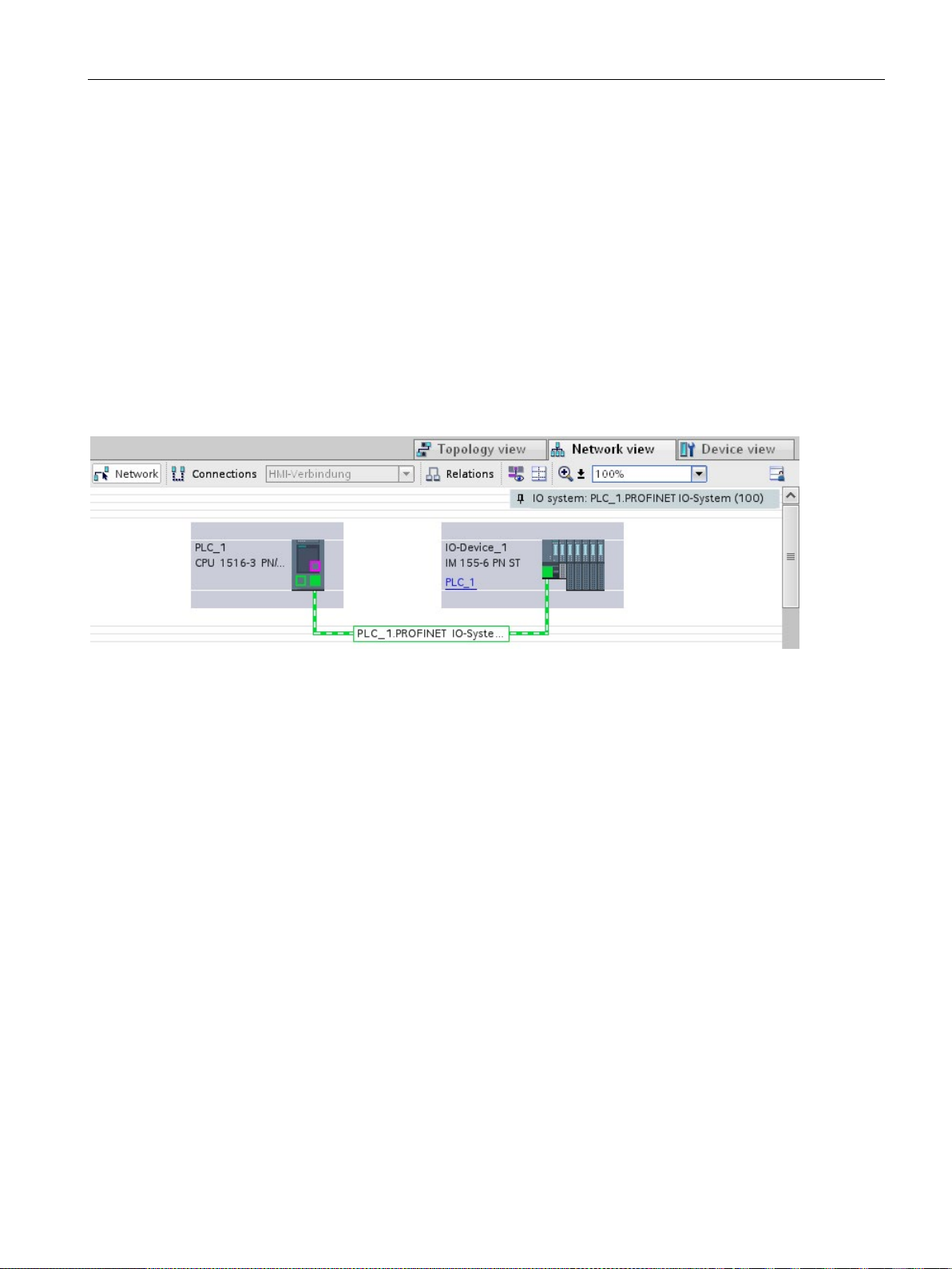
A PROFINET IO system is comprised of a PROFINET IO controller and its assigned
PROFINET IO devices. After these devices have been placed in the network or topology
view, STEP 7 assigns default values for them. Initially, you only have to worry about the
assignment of IO devices to an IO controller.
● You are in the network view of STEP 7.
● A CPU has been placed (e.g., CPU 1516-3 PN/DP).
● An IO device has been placed (e.g., IM 155-6 PN ST).
PROFINET with STEP 7 V14
42 Function Manual, 09/2016, A5E03444486-AG
Page 43
Parameter assignment/addressing
Procedure
Result
Checking the assignment
3.1 Assigning an IO device to an IO controller
To assign IO devices to an IO controller, proceed as follows:
1. Place the pointer of the mouse over the interface of the IO device.
2. Press and hold down the left mouse button.
3. Move the pointer.
The pointer now uses the networking symbol to indicate "Networking" mode. At the same
time, you see the lock symbol on the pointer. The lock symbol disappears only when the
pointer is over a valid target position.
4. Now move the pointer onto the interface of the IO controller. You can keep the left mouse
button pressed or release it when performing this action.
5. Now release the left mouse button or press it again (depending on your previous action).
Figure 3-1 Assigning an IO device to an IO controller in the network view of STEP 7
You have assigned an IO device to an IO controller.
You can find an overview of the communication relationships in the "IO communication" tab
in the tabular area of the network view. This table is context-sensitive for selection in the
graphic area:
● Selection of the interface shows the I/O communication of the respective interface.
● Selection of the CPU shows all I/O communication of the CPU (including PROFIBUS).
● Selection of the station (as in the above figure) interface shows the I/O communication of
the complete station.
PROFINET with STEP 7 V14
Function Manual, 09/2016, A5E03444486-AG
43
Page 44
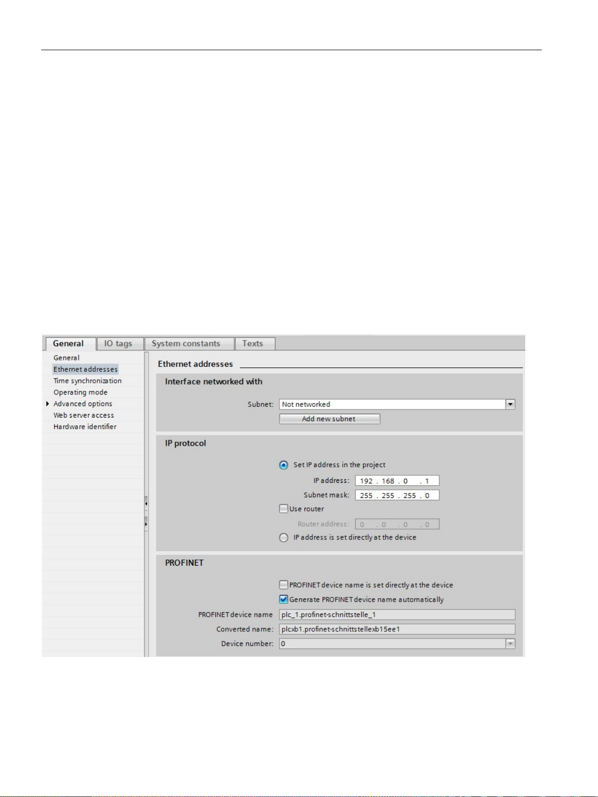
Parameter assignment/addressing
3.2
Device name and IP address
Introduction
In STEP 7
3.2 Device name and IP address
In order that the PROFINET device can be addressed as node on PROFINET, the following
are required:
● A unique PROFINET device name
● A unique IP address in the relevant IP subnet
STEP 7 assigns a device name during the arrangement of a PROFINET device in the
hardware and network editor. The IP addresses are typically assigned automatically by
STEP 7 and assigned to the devices based on the device name.
You can change the name and IP address manually.
You can find the device name and the IP address under "Ethernet addresses" in the
properties of the PROFINET interface in the Inspector window.
Figure 3-2 Device name and IP address in STEP 7
The function, the assignment and the changing of the device name and the IP address are
described in the following sections.
PROFINET with STEP 7 V14
44 Function Manual, 09/2016, A5E03444486-AG
Page 45

Parameter assignment/addressing
3.2.1
Device name
Device names
Structured device names
3.2 Device name and IP address
Before an IO device can be addressed by an IO controller, it must have a device name. In
PROFINET, this method was selected because it is simpler to work with names than with
complex IP addresses.
The assignment of a device name for a specific IO device can be compared to setting the
PROFIBUS address of a DP slave.
In delivery state, an IO device does not have a device name. A device name must first be
assigned before an IO device can be addressed by an IO controller, for example, for
transferring configuration data during startup or for exchanging user data in cyclic mode. You
assign the device names to the IO device, for example, with the programming device / PC.
IO devices that have a slot for removable storage media provide the option of writing the
device name directly to the removable storage medium in the programming device.
When a device is replaced by a device without removable medium, the IO controller assigns
the device name based on topological configuration (see section Configuring topology
(Page 59)).
The device name is automatically assigned by default for PROFINET devices S7-1200,
S7-1500, ET 200MP, ET 200SP and ET 200AL when these are configured in STEP 7. The
device names are formed from the name of the CPU or the name of the interface module.
For devices with several PROFINET interfaces, the name of the interface is enhanced, for
example, "plc_1.profinet-interface_2" or "io-device_1".
You can structure the device names using DNS conventions.
These conventions are defined by "Internationalizing Domain Names in Applications (IDNA).
According to this, device names are written in lower case.
The "Domain Name System" (DNS) is a distributed database (http://iana.org
manages the name space on the Internet. To structure the names, you use the dot ("."). The
hierarchy is shown in ascending order from left to right.
...<Subdomain name>.<Domain name>.<Top-level domain name>
If the name is not DNS-compliant, the name will be converted by STEP 7, for example, to
"plcxb1.profinet-schnittstellexb2022c" or "io-devicexb15b32".
), which
PROFINET with STEP 7 V14
Function Manual, 09/2016, A5E03444486-AG
45
Page 46
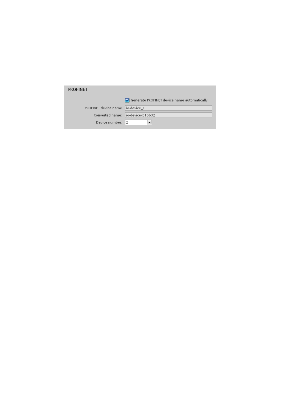
Parameter assignment/addressing
Device number
3.2.2
IP address
IP address
Configuration of the IP address
3.2 Device name and IP address
In addition to the device name, STEP 7 also assigns a device number beginning with "1"
when an IO device is allocated.
The device number is located in the Inspector window in the properties of the PROFINET
interface, under "Ethernet addresses" in the area PROFINET.
Figure 3-3 Device number
This device number can be used to identify an IO device in the user program (for example,
with the instruction "LOG2GEO").
To allow a PROFINET device to be addressed as a device on Industrial Ethernet, this device
also requires an IP address that is unique within the network. The IP addresses are typically
assigned automatically by STEP 7 and assigned to the devices based on the device name. If
it is a standalone network, you can apply the IP address and subnet mask suggested by
STEP 7. If the network is part of an existing Ethernet company network, obtain the
information from your network administrator.
In accordance with Internet Protocol version 4 (IPv4), the IP address is made up of four
decimal numbers with a range of values from 0 through 255. The decimal numbers are
separated by periods (for example, 192.162.0.0).
The IP address consists of the following:
● Address of the network
● Address of the device (PROFINET interface of the IO controller/IO device)
PROFINET with STEP 7 V14
46 Function Manual, 09/2016, A5E03444486-AG
Page 47

Parameter assignment/addressing
Generating IP addresses
Subnet mask
Example of the subnet mask
Default router
3.2 Device name and IP address
The IP addresses of the IO devices are generated by STEP 7 and first assigned to the
IO devices when the CPU starts up. In addition, for some IO devices (e.g., SCALANCE X,
S7-300 CPs), it is possible not to obtain the IP address during startup of the IO controller, but
rather to set it beforehand on the device (see Permitting changes to the device name and IP
address directly on the device (Page 57)).
The IP addresses of the IO devices always have the same subnet mask as the IO controller
and are assigned from the IP address of the IO controller in ascending order. The IP address
can be changed manually, if necessary.
For devices with several PROFINET interfaces (e.g., CPU 1516-3 PN/DP), the IP addresses
must be located in different subnets.
The bits set in the subnet mask decide the part of the IP address that contains the address
of the network.
In general, the following applies:
● The network address is obtained from the AND operation of the IP address and subnet
mask.
● The device address is obtained from the AND NOT operation of the IP address and
subnet mask.
Subnet mask: 255.255.0.0 (decimal) = 11111111.11111111.00000000.00000000 (binary)
IP address: 192.168.0.2 (decimal) = 11000000.10101000.00000000.00000010 (binary)
Meaning: The first 2 bytes of the IP address determine the network - i.e., 192.168. The last
two bytes address the device, i.e. 0.2.
The default router is used when data has to be forwarded via TCP/IP or UDP to a partner
located outside the local network.
In STEP 7, the default router is named Router. You can activate the use of a router in the
Inspector window of a CPU with the "Use router" check box in the"IP protocol" section.
STEP 7 assigns the local IP address to the default router by default.
The router address that is set on the PROFINET interface of the IO controller is
automatically transferred for the configured IO devices.
PROFINET with STEP 7 V14
Function Manual, 09/2016, A5E03444486-AG
47
Page 48

Parameter assignment/addressing
Relation between IP address and default subnet mask
IP address (decimal)
IP address (binary)
Address class
Default subnet mask
0 to 126
0xxxxxxx.xxxxxxxx....
A
255.0.0.0
192 to 223
110xxxxx.xxxxxxxx...
C
255.255.255.0
Note
Range of values for the first decimal point
A value between 224 and 255 is also possible for the first decimal number of the IP address
(address class D etc.). However, this is not recommended because there is no address
check for
Masking other subnets
Masks
Decimal
Binary
00000000
00000000
Reading out an IP address in the user program
3.2 Device name and IP address
An agreement exists relating to the assignment of IP address ranges and so-called "Default
subnet masks". The first decimal number (from the left) in the IP address determines the
structure of the default subnet mask with respect to the number of "1" values (binary) as
follows:
128 to 191 10xxxxxx.xxxxxxxx... B 255.255.0.0
these values.
You can use the subnet mask to add further structures and form "private" subnets for a
subnet that is assigned one of the address classes A, B or C. This is done by setting other,
less significant bits of the subnet mask to "1". For each bit set to "1", the number of "private"
networks doubles and the number of devices they contain is halved. Externally, the network
continues to function as an individual network.
Example:
You have a subnet of address class B (for example, IP address 129.80.xxx.xxx) and change
the default subnet mask as follows:
Default subnet mask 255.255.0.0 11111111.11111111.00000000.
Subnet mask 255.255.128.0 11111111.11111111.10000000.
Result:
All devices with addresses from 129.80.001.000 to 129.80.127.254 are located in a subnet,
all devices with addresses from 129.80.128.000 to 129.80.255.254 in a different subnet.
You can read out the IP address of a PROFINET device in the user program of a
S7-1500 CPU. You can find information in this FAQ
(https://support.industry.siemens.com/cs/ww/en/view/82947835
PROFINET with STEP 7 V14
48 Function Manual, 09/2016, A5E03444486-AG
).
Page 49

Parameter assignment/addressing
3.2.3
Assigning a device name and IP address
Assigning an IP address and subnet mask for an IO controller for the first time
Using a programming device or PC:
Using the display of a S7-1500 CPU:
Using a memory card:
Assigning device names and IP address for "Device replacement without exchangeable
medium/programming device"
3.2 Device name and IP address
You have the following options:
●
Connect your programming device/PC to the same network as the relevant PROFINET
device. The interface of the programming device/PC must be set to TCP/IP mode. During
the download, first of all display all available devices via the "Accessible devices"
download dialog box. Select the target device via its MAC address and then assign its IP
address before you download the hardware configuration including the configured IP
address (IP address is saved retentively).
●
The S7-1500 CPUs have a front cover with a display and operating keys. You can use
this display to assign or change the IP address. To set the IP address, navigate on the
display via the menu items "Settings" > "Addresses" > "X1 (IE/PN)" > "Parameters".
●
If your PROFINET device is equipped for a memory card (Micro Memory Card/SIMATIC
memory card), plug this into your programming device/PC and save the hardware
configuration together with the configured IP address on this memory card. Then plug the
memory card into the PROFINET device. Once inserted, the PROFINET device
automatically applies the IP address.
If you have saved a configuration to the memory card with the "IP address is set directly
at the device" option, you must assign the IP address using a different method after
inserting the memory card (see section Permitting changes to the device name and IP
address directly on the device (Page 57)).
For devices without exchangeable medium (e.g., ET 200MP, ET 200SP) and devices that
support "Device replacement without exchangeable medium/PG" (e.g., ET 200S), the IO
controller can identify the device without name from the neighbor relationships specified by
the set topology and from actual neighbor relationships determined by the real PROFINET
devices. The IO controller then assigns the PROFINET device the configured name and
incorporates the PROFINET device in the user data traffic. (See also Device replacement
without exchangeable medium (Page 193)).
PROFINET with STEP 7 V14
Function Manual, 09/2016, A5E03444486-AG
49
Page 50
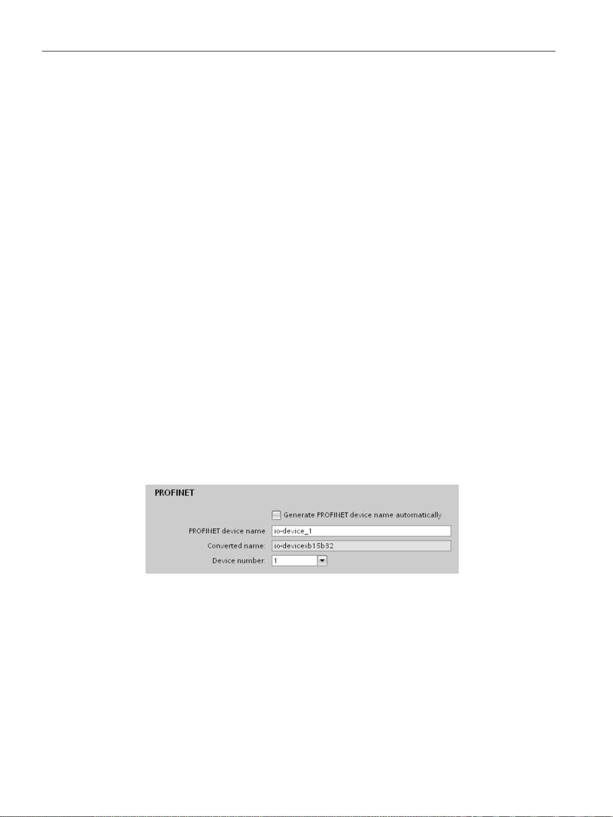
Parameter assignment/addressing
IP address assignment when replacing IO devices with exchangeable mediumPG
Procedure: Changing the device name using properties of the PROFINET interface
3.2 Device name and IP address
The following is contained on the memory card of the programmable logic controller:
● On the IO controller: Device name and IP address
● On the IO device: Device name
When you remove the memory card from a PROFINET device and insert it in another
PROFINET device with exchangeable medium (e.g., ET 200S), device-specific information
and the device name are loaded to the device.
If an IO device has to be replaced in its entirety due to a device or module defect, the IO
controller automatically assigns parameters and configures the replaced device or module.
The cyclic exchange of user data is then restarted. In addition to this, before the power ON
of the IO device, the memory card with the valid name must be removed from the faulty IO
device and added to the replaced device.
In the event of an error in the PROFINET device, the memory card allows you to replace a
module without a programming device/PC. You can also transfer the device data directly
from the programming device/PC to the memory card.
You can change the PROFINET name via the properties of the PROFINET interface. This is
useful when the PROFINET device has not received its previous name from the automatic
generation, for example, in the case of a migration.
1. In the network or device view of the STEP 7 hardware and network editor, select the
PROFINET interface of a PROFINET device.
2. In the Inspector window, go to "Ethernet addresses" in the PROFINET area.
3. Clear the "Generate PROFINET device name automatically" check box.
4. Enter the new PROFINET device name in the relevant field.
Figure 3-4 Changing the device name of a PROFINET device in the properties
PROFINET with STEP 7 V14
50 Function Manual, 09/2016, A5E03444486-AG
Page 51
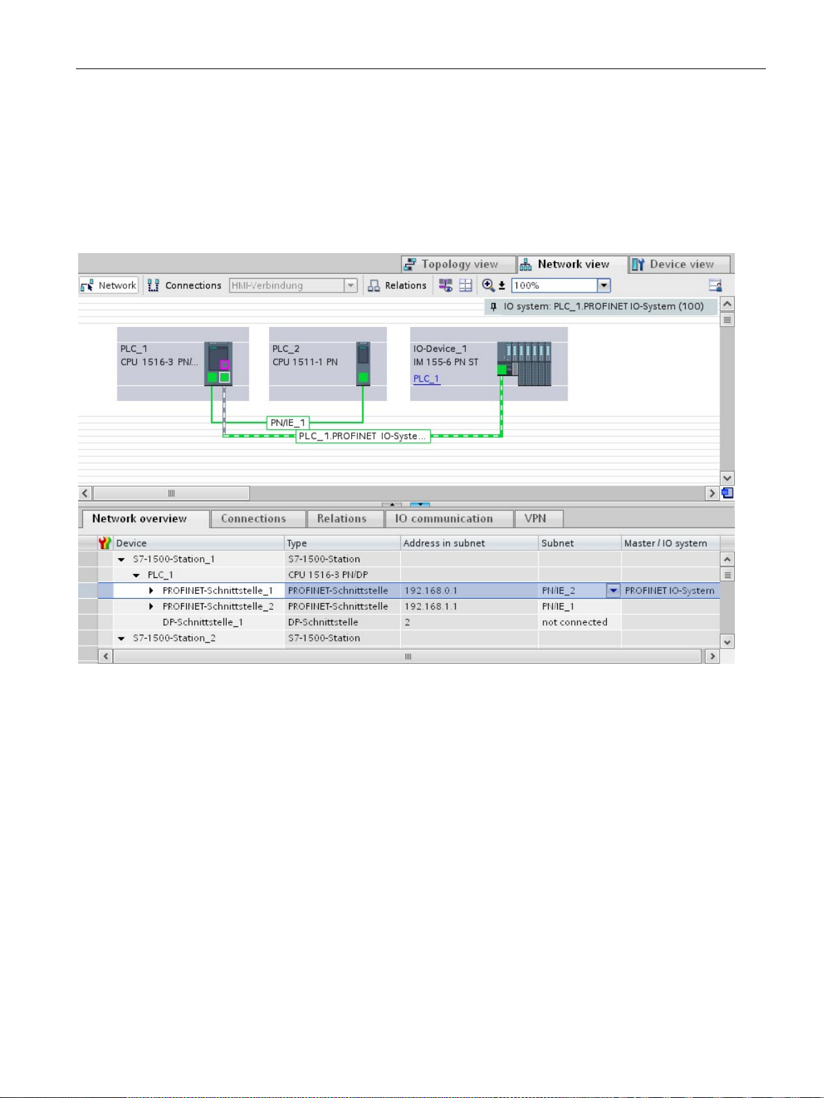
Parameter assignment/addressing
Alternative procedure: Changing the device name of a PROFINET device in the network view
Procedure: Changing the IP address
3.2 Device name and IP address
Requirement: The "Generate PROFINET device name automatically" check box is selected.
1. In STEP 7, select the "Network overview" tab in the tabular area of the network view.
2. In the "Device" column, overwrite the name in the row of the relevant PROFINET device.
The name is also changed accordingly in the graphic area of the network view.
Figure 3-5 Changing the device name of a PROFINET device in STEP 7
To change the IP address, follow these steps:
1. In the network or device view of the STEP 7 hardware and network editor, select the
PROFINET interface of a PROFINET device.
2. In the Inspector window, go to "Ethernet addresses" in the "IP protocol" area.
PROFINET with STEP 7 V14
Function Manual, 09/2016, A5E03444486-AG
51
Page 52
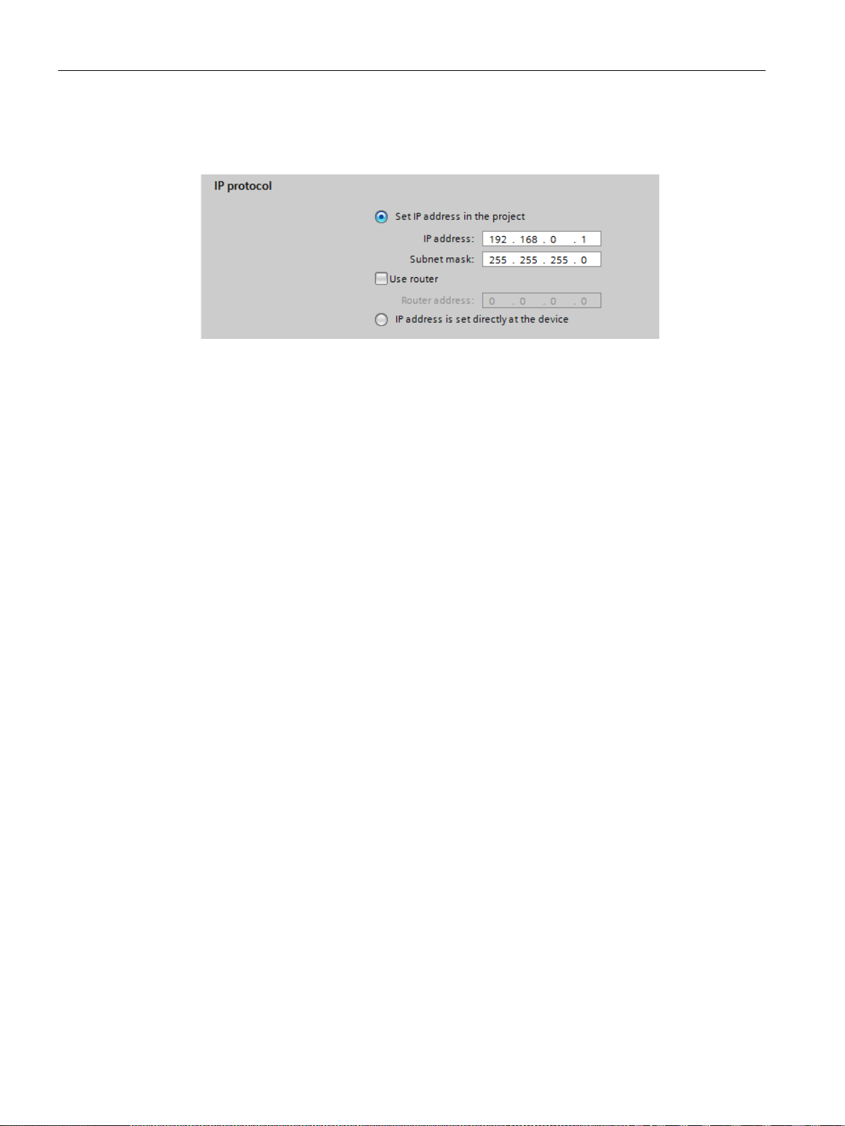
Parameter assignment/addressing
Downloading configured device name to IO device
3.2 Device name and IP address
3. Check that the option "Set IP address in the project" is selected.
4. Enter the new IP address in the relevant field.
Figure 3-6 Changing the IP address of a PROFINET device in STEP 7
To load the configured device names to the IO device, follow these steps:
1. Connect your programming device/PC to the same network as the relevant IO device.
The interface of the programming device/PC must be set to TCP/IP mode.
2. In STEP 7, select the relevant IO device in the "Accessible devices" dialog based on the
MAC address.
3. Click "Assign name" to download the configured device name to the IO device.
The IO controller recognizes the IO device automatically by its device name and
automatically assigns the configured IP address to it.
PROFINET with STEP 7 V14
52 Function Manual, 09/2016, A5E03444486-AG
Page 53
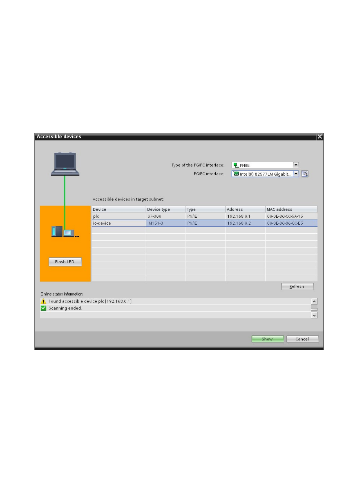
Parameter assignment/addressing
Identification of the PROFINET device
Online > Accessible devices...
Using an different way to assign IP addresses for IO devices
3.2 Device name and IP address
To clearly identify a device from several identical devices in a control cabinet, for example,
you can flash the link LED of the PROFINET device.
To do this, select the menu command
in STEP 7. In the
"Accessible devices" dialog, set the "PG/PC" interface by means of which you are connected
to the devices. STEP 7 now automatically searches for the accessible devices and displays
them in the "Accessible devices in target subnet" table. Select the desired PROFINET device
and click on the "Flash LED" button. The PROFINET device is identified based on its MAC
address.
Figure 3-7 "Accessible devices" dialog
Various IO devices, for example, SCALANCE X,S7-300 CPs, support the option of not
having the IP addresses assigned by the IO controller during startup. In this case, the IP
address is assigned in a different way. For additional information, refer to the manual of the
respective PROFINET device of the SIMATIC device family.
PROFINET with STEP 7 V14
Function Manual, 09/2016, A5E03444486-AG
53
Page 54
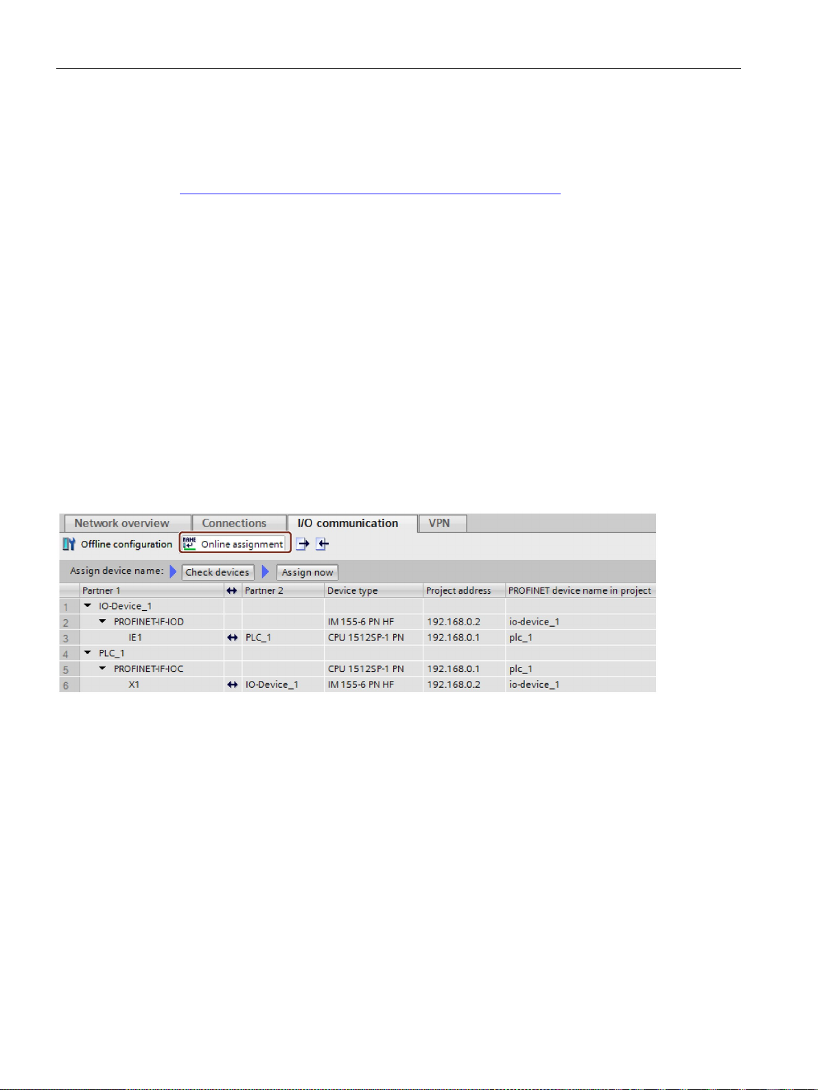
Parameter assignment/addressing
Additional information
3.2.4
Assign device name via communication table
Introduction
"Online assignment" tab
3.2 Device name and IP address
You can find a detailed description of the operation and functions of the display of the
S7-1500 CPUs in the system manual S7-1500, ET 200MP
).
(http://support.automation.siemens.com/WW/view/en/59191792
You can assign the device names of PROFINET IO devices configured offline to the devices
online. You can do this in the table area of the network view in the table "I/O
communication". You can also assign the device names to several devices at the same time.
In the I/O communication table, you will find the tabs "Offline configuration" and "Online
assignment". In the "Online assignment" tab, you can assign the PROFINET device names
that were assigned offline to the corresponding IO devices online. To do this, use the buttons
"Check devices" and "Assign now".
Figure 3-8 Assign device name via communication table
The objects displayed in the table of the "Online assignment" tab depend on the setting of
the filter function. If only selected objects should be displayed, only objects of the
corresponding context are displayed depending on the selection in the network view.
● PROFINET subnet: All connected devices and their PROFINET interfaces
● IO system All devices involved and their PROFINET interfaces
● Sync domain: All devices involved and their PROFINET interfaces
● Devices: The device and any existing PROFINET interfaces
● Other subnets or interfaces such as MPI or PROFIBUS are not displayed
If the display is set for all devices using the filter function, all devices are displayed that have
a PROFINET interface, regardless of whether they are connected via a PROFINET subnet
or are part of an IO system. Devices without a PROFINET interface, for example only with a
DP or MPI interface, are not displayed.
PROFINET with STEP 7 V14
54 Function Manual, 09/2016, A5E03444486-AG
Page 55

Parameter assignment/addressing
General procedure
Requirements
Procedure (step 1)
Note
You can enter, insert or import the
is automatically entered in the cell. The following entries are supported and then
converted to the required format:
•
•
•
The formats used in the exampl
Intermediate result
Status
Meaning
3.2 Device name and IP address
To assign PROFINET device names, you must first detect the IO devices available online.
With this procedure, it matters whether the MAC addresses are known or unknown. This
results in a general procedure in two steps:
1. Detecting the IO devices available online
2. Assigning configured PROFINET device names to the IO devices available online
● You are in the network view.
● There is an online connection to the devices.
To detect IO devices available online from the I/O communication table, follow these steps:
1. Optional: Entered known MAC addresses in the "MAC address" column. After every valid
entry, the check box under "Assign device" is selected for the relevant row.
2. Click "Check devices" to start the check of the IO devices available online.
3. Set the PG/PC interface in the dialog window and click "Start".
After the check, the result is displayed for every device in the table. Online data found is
automatically entered in the table and the check box "Assign device" is set to "checked" in
the rows in which a MAC address was entered or found online. The result of the check is
shown as an icon in the "Status" column.
Matching device and compatible type
Matching device and incompatible type
MAC address in different formats. The correct format
"08:00:06:BA:1F:20"
"08 00 06 BA 1F 20"
"080006BA1F20"
e are automatically converted to "08-00-06-BA-1F-20".
Non-matching device
Device cannot be reached (with a known MAC address)
Ready for assignment (with known MAC address)
PROFINET with STEP 7 V14
Function Manual, 09/2016, A5E03444486-AG
55
Page 56

Parameter assignment/addressing
Note
The icon "Ready for assignment" appears when a MAC address exists and matching device
data was found, but no PROFINET device name was found online.
Procedure (step 2)
Note
The bulk operation cannot be reversed. A message to this effect appears in a dialog
window.
Result
Importing and exporting data
3.2 Device name and IP address
You can update the data of the detected devices again via their MAC addresses at any time.
To do this, you specify the MAC address and the status of the device is displayed
immediately without having to re-detect the device.
All PROFINET device names configured offline will be assigned to the devices available
online in a bulk operation.
1. Click the "Assign now" button.
2. Click "Start" in the dialog window to start the assignment of the PROFINET device
names.
The PROFINET device names configured offline will be assigned to the devices available
online. This relates to devices in whose row the check box under "Assign device" is selected,
that have a MAC address and have the status "Ready for assignment".
Using the import and export button, you can import or export the data of the I/O
communication table for the online assignment:
● When you export, the currently displayed data of the table is exported to a CSV file. Using
the filter function of the table, you can select which data will be exported.
● When you import, the data of the CSV file is written to the table. If there are conflicts with
values already existing in the table, you can decide whether the data should be
overwritten or whether the import needs to be stopped.
PROFINET with STEP 7 V14
56 Function Manual, 09/2016, A5E03444486-AG
Page 57
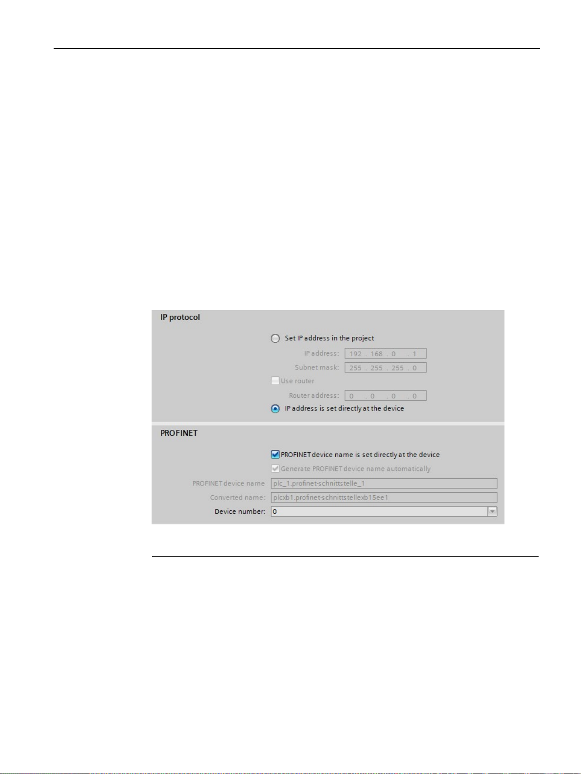
Parameter assignment/addressing
3.2.5
Permitting changes to the device name and IP address directly on the device
Introduction
Procedure
Note
Gateway
When you operate a PROFINET device with the option "Allow adaption of the device
name/IP address directly on device", you cannot use this PROFINET device as gateway
for S7 routing.
3.2 Device name and IP address
Machines are frequently commissioned on site or integrated into the existing infrastructure
without STEP 7. You can find typical applications in all areas of the series machine building.
Alternative means for assigning the IP address are available for this.
1. In the network or device view of the STEP 7 Hardware and Network editor, select the
PROFINET interface of an IO controller.
2. Navigate in the Inspector window to "Ethernet addresses".
3. Select the "IP address is set directly at the device" option in the "IP protocol" area.
4. In the "PROFINET" area, select the " PROFINET device name is set directly at the
device" check box.
Figure 3-9 Setting the device name and IP address on the device
PROFINET with STEP 7 V14
Function Manual, 09/2016, A5E03444486-AG
57
Page 58

Parameter assignment/addressing
Options for assigning IP addresses and device names
Additional information
3.2 Device name and IP address
Apart from the known address and device name assignment in the "Ethernet addresses"
section of the Inspector window, there are other ways in which the IP address and name can
be assigned:
● Assigning by means of the user program with the instruction "T_CONFIG"
● Assignment when downloading the configuration to the target system via the "Extended
download to device" dialog box.
● Assignment via the Primary Setup Tool (PST)
● Assignment via the PRONETA ("PROFINET network analysis") commissioning and
diagnostics tool
● Assignment via the SIMATIC Automation Tool
For information on the "T_CONFIG" instruction and on downloading to the target system,
refer to the STEP 7 online help.
A free Download (http://support.automation.siemens.com/WW/view/en/14929629
Primary Setup Tool (PST) can be found on the Internet. On this Internet page, you will also
find a list of devices for which the PST is approved.
) of the
PROFINET with STEP 7 V14
58 Function Manual, 09/2016, A5E03444486-AG
Page 59

Parameter assignment/addressing
3.3
Configuring topology
Introduction
Line
Star
Tree
Ring
3.3 Configuring topology
If an IO device is assigned to an IO controller, this does not yet specify how the ports are
connected to each other.
A port interconnection is not required to use RT, but it provides the following advantages:
● A set topology is assigned with the port interconnection. Based on an online-offline
comparison, it is possible to conduct a set-actual comparison with all devices that support
this function.
● The "Device replacement without exchangeable medium" function can be used.
A port interconnection is an essential requirement for using IRT.
An overview of various options for setting up a PROFINET network is given below.
All the communication devices are connected in a linear bus topology.
In PROFINET, the linear bus topology is implemented with switches that are already
integrated into the PROFINET devices. Therefore, the linear bus topology at PROFINET is
merely a special form of tree / star topology.
If a link element (switch, for example) fails, communication across the failed link element is
no longer possible. The network is then divided into 2 subsegments.
Linear bus topology structures require the least cabling.
If you connect communication devices to a switch with more than two PROFINET ports, you
automatically create a star network topology.
If an individual PROFINET device fails, this does not automatically lead to failure of the
entire network, in contrast to other structures. It is only if a switch fails that part of the
communication network will fail as well
If you interconnect several star structures, you obtain a tree network topology.
In order to increase the availability of a network, use ring structures. In principle, a linear bus
topology is connected to a ring through a so-called redundancy manager.
The task of the redundancy manager is managed by an external switch SCALANCE X, a
CPU that supports the Media Redundancy Protocol MRP (e.g., CPU 1516-3 PN/DP) or a CP
(e.g., CP 343-1 Lean).
If there is a break in the network, the redundancy manager ensures that the data is
redirected over an alternative network connection in the ring.
PROFINET with STEP 7 V14
Function Manual, 09/2016, A5E03444486-AG
59
Page 60
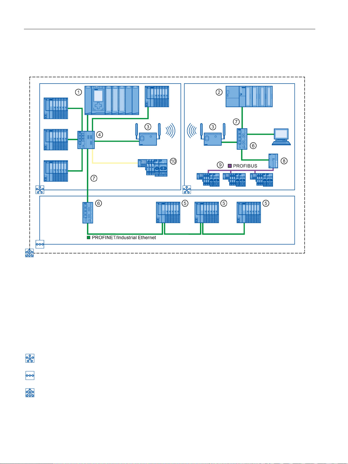
Parameter assignment/addressing
Example for topology
Number
Meaning
①
S7-1500 as IO controller
②
S7-300 as IO controller
③
Industrial WLAN with SCALANCE W
④
SCALANCE X 307-3 with seven electrical and three optical ports
⑤
ET 200SP with integrated 2-port switch
⑥
SCALANCE X 204 with four electrical ports
⑦
PROFINET/Industrial Ethernet
⑧
IE/PB-Link PN IO
⑨
PROFIBUS DP
⑩
ET 200S with two optical ports
3.3 Configuring topology
The following example shows a combination of different topologies.
Star topology
Linear bus topology
The combination of topology forms results in a tree topology.
Figure 3-10 Combined topology
PROFINET with STEP 7 V14
60 Function Manual, 09/2016, A5E03444486-AG
Page 61

Parameter assignment/addressing
Additional information
3.3.1
Topology view in STEP 7
Introduction
3.3 Configuring topology
Observe the PROFINET Installation Guideline
http://www.profibus.com/nc/download/installation-guide/downloads/profinet-installation-
(
guide/display/) of the PROFIBUS User Organization when planning your PROFINET
topology.
For more detailed information, see the SIMATIC NET Twisted Pair and Fiber Optic Networks
) manual.
) manual.
(http://support.automation.siemens.com/WW/view/en/8763736
You can find basic information in the Communication with SIMATIC
(http://support.automation.siemens.com/WW/view/en/1254686
The topology view is one of three working areas of the hardware and network editor. You
undertake the following tasks here:
● Displaying the Ethernet topology
● Configuring the Ethernet topology
● Identify and minimize differences between the set and actual topology (online)
The topology view in STEP 7 consists of a graphic area and a table area.
PROFINET with STEP 7 V14
Function Manual, 09/2016, A5E03444486-AG
61
Page 62
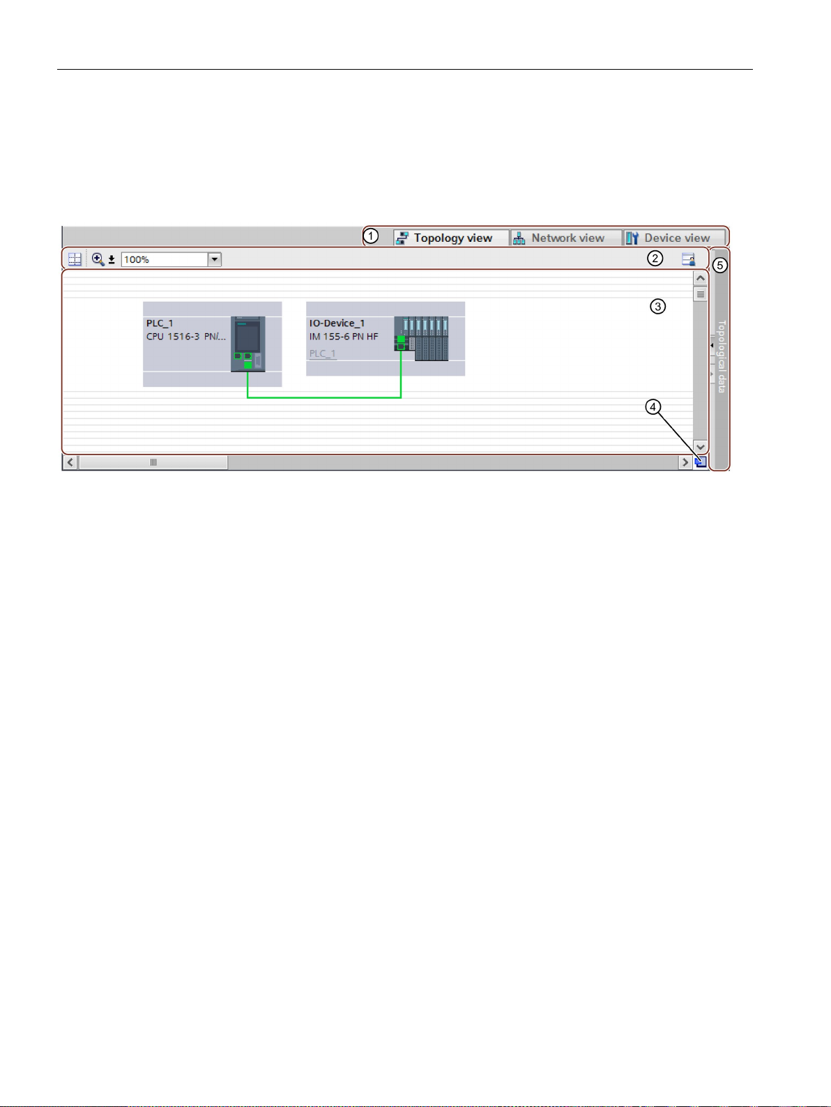
Parameter assignment/addressing
Graphic area
①
Selector: Device view/Network view/Topology view
②
Toolbar
③
Graphic area of the topology view
④
Overview navigation
⑤
Selector for the table area of the topology view
Overview navigation
3.3 Configuring topology
The graphic area of the topology view displays PROFINET devices with their appropriate
ports and port connections. Here you can add more PROFINET devices.
The following figure shows the graphic area of the topology view.
Figure 3-11 Graphic area of the topology view
Click in the overview navigation to obtain an overview of the created objects in the graphic
area. By holding down the mouse button, you can quickly navigate to the desired objects and
display them in the graphic area.
PROFINET with STEP 7 V14
62 Function Manual, 09/2016, A5E03444486-AG
Page 63
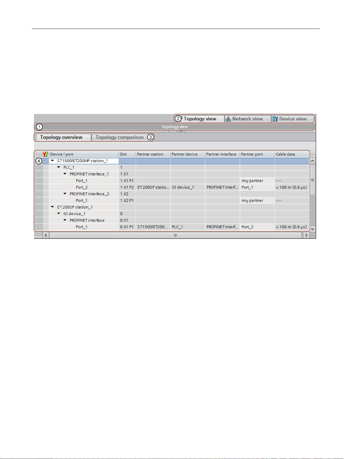
Parameter assignment/addressing
Table area
①
Selector for the graphic area of the topology view
②
Selector: Device view/Network view/Topology view
③
Selector: Topology overview/Topology comparison
④
Table area of the topology view
3.3 Configuring topology
● Topology overview: This displays the Ethernet or PROFINET devices with their
appropriate ports and port connections in a table. This table corresponds to the network
overview table in the network view.
● Topology comparison: Here you can import devices and port interconnections
automatically through offline/online comparison or extended Offline/Online comparison
into STEP 7.
Figure 3-12 Table area of the topology view
PROFINET with STEP 7 V14
Function Manual, 09/2016, A5E03444486-AG
63
Page 64
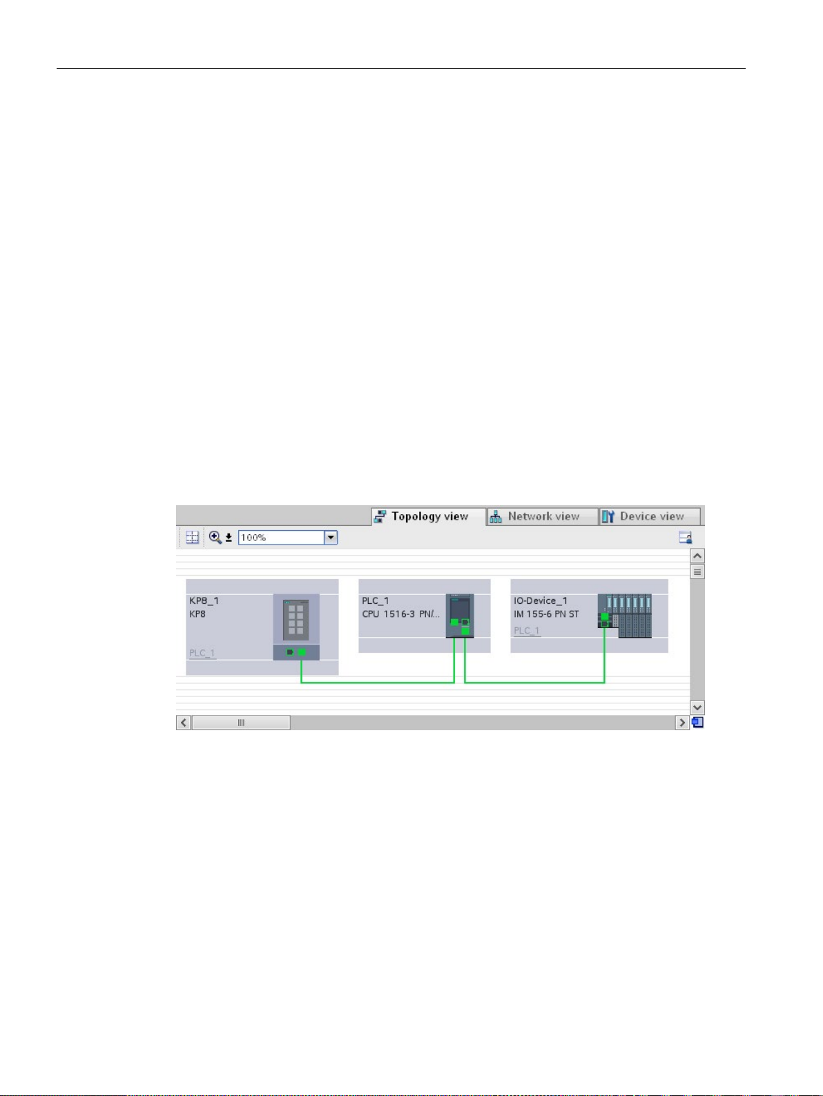
Parameter assignment/addressing
3.3.2
Interconnecting ports in the topology view
Requirement
Procedure
Result
3.3 Configuring topology
You are in the graphic view of the topology view.
To interconnect ports in the topology view, follow these steps:
1. Place the pointer of the mouse on the port you want to interconnect.
2. Press and hold down the left mouse button.
3. Move the pointer.
The pointer now uses the networking symbol to indicate "Interconnecting" mode. At the
same time, you see the lock symbol on the pointer. The lock symbol disappears only
when the pointer is over a valid target position.
4. Now drag the pointer to the target port. You can keep the left mouse button pressed or
release it when performing this action.
5. Now release the left mouse button or press it again (depending on your previous action).
Figure 3-13 Interconnecting ports in the topology view
You have created a port interconnection.
PROFINET with STEP 7 V14
64 Function Manual, 09/2016, A5E03444486-AG
Page 65
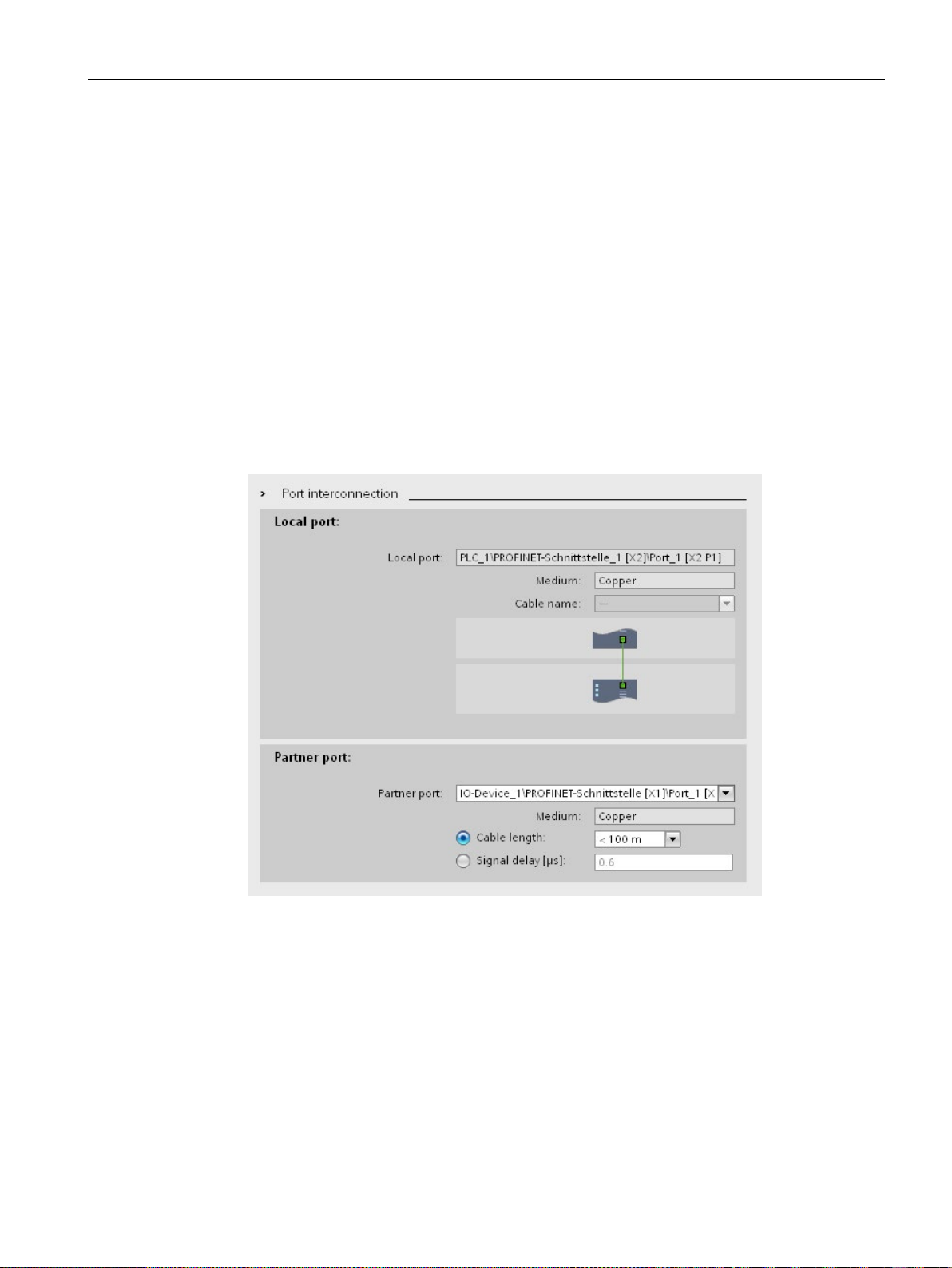
Parameter assignment/addressing
3.3.3
Interconnecting ports - Inspector window
Interconnecting ports in the Inspector window
3.3 Configuring topology
To interconnect ports, follow these steps:
1. In the device or network view, select the PROFINET device or PROFINET interface.
2. In the Inspector window, navigate to the port property "Port interconnection".
When the PROFINET interface is selected, you can find this setting in the Inspector
window as follows: "Properties > General > Advanced Options > Port [...] > Port
Interconnection."
3. In the "Local port" section, you can find the settings at the local port. In the case of fiber-
optic cable you can, for example, set the cable names here.
In the "Partner port" area, select the drop-down list for "Partner port" in order to display
the available partner ports and make a selection.
Figure 3-14 Interconnecting ports in the Inspector window in STEP 7
If the PROFINET interface was disconnected, it is automatically connected by this action. In
the properties of the subnet you can set whether this subnet should or should not be used for
the networking.
PROFINET with STEP 7 V14
Function Manual, 09/2016, A5E03444486-AG
65
Page 66

Parameter assignment/addressing
3.3.4
Automatic assignment of devices by offline/online comparison
Overview
Start of availability detection
Note
The availability detection can take several seconds. During this time, no user input is
possible.
Automatic assignment of a PNIO device
No automatic assignment
3.3 Configuring topology
During the offline/online comparison, the configured topology is compared with the actual
existing topology. Devices identified online are automatically assigned to configured devices
as far as this is possible.
You start the availability detection the first time by clicking the "Compare offline/online"
button in the toolbar of the "Topology comparison" tab.
You restart availability detection by clicking the "Update" button.
A PNIO device identified online is automatically assigned to a configured device if the
following properties of the two devices match up:
● Article no.
● Type
● PROFINET device name
In the following situations, no automatic assignment is possible:
● No device can be identified online to match a configured device. (This means that the
corresponding columns in the "Online topology" area of the topology comparison table
are empty.)
In this case, you should add the already configured device to your system or delete the
configured device from the configuration.
● A device identified online can be assigned to a configured device, but there are
differences in the port interconnections.
In this case, you can Apply the port interconnections identified online manually to the
project (Page 67).
● A device identified online cannot be assigned to a configured device. (In this case, the
corresponding columns in the "Offline topology" area of the topology comparison table
are empty.)
In this case, you can Include the devices identified online manually in the project
(Page 68).
PROFINET with STEP 7 V14
66 Function Manual, 09/2016, A5E03444486-AG
Page 67

Parameter assignment/addressing
3.3.5
Apply the port interconnections identified online manually to the project
Requirements
Procedure
Result
Note
If other port interconnections are recognized for a device identified online and these differ
from those that exist in the project, adopting these in the project means that the port
interconnections that were previously in the project are replaced by those identified online. If
no port interconnections are detected for a device identified online, adopting in the project
means that all the port interconnections of this device are delet
3.3 Configuring topology
You have run an offline/online comparison in the topology view. The result of this is that at
least one device identified online was automatically assigned to a configured device, but that
there are differences relating to the interconnection.
To adopt one more port interconnections identified online in the project manually, follow
these steps:
1. Select the row belonging to the port interconnection.
2. If applicable, select further roles using multi-selection.
3. Select "Apply" > "Use selected" in the shortcut menu.
The content of the corresponding table cells in the "Action" column changes to "Apply".
4. If you have mistakenly prepared too many port interconnections to be included in the
project:
Select the rows belonging to the port interconnections you have mistakenly prepared for
inclusion in the project using multi-selection.
Select "Reset" > "Reset selected" in the shortcut menu.
The content of the corresponding table cells in the "Action" column change to "No action".
5. Click the "Synchronize" button.
The port interconnections identified online for the corresponding devices are included in the
project. Successful adoption is indicated by the diagnostics icon "Identical topology
information" for each port.
ed in the project.
PROFINET with STEP 7 V14
Function Manual, 09/2016, A5E03444486-AG
67
Page 68

Parameter assignment/addressing
3.3.6
Include the devices identified online manually in the project
Requirements
Procedure
Result
3.3.7
Automatic assignment of devices by advanced offline/online comparison
Overview
Automatic assignment of devices detected by ICMP
3.3 Configuring topology
You have run an offline/online comparison in the topology view. The result of this is that at
least one device identified online could not be assigned to any configured device.
To adopt one more devices identified online in the project manually, follow these steps:
1. For a configured device without an online partner, move the mouse pointer to the
"Device/port" column of the online topology.
2. Select the device you want to assign to the configured device from the drop-down list of
this box.
3. Repeat the previous steps if necessary for other configured devices without an online
partner.
The selected device that was identified online is moved up from the end of the table.
Following this, it is in the row of the configured device to which you have just assigned it.
With the advanced offline/online comparison, ICMP is also used alongside DCP to be able to
detect devices that do not support DCP.
With devices detected by ICMP, no type is available.
With passive devices, no article number is available. For this reason, passive devices can
only be assigned automatically if you have not assigned an article number in the configured
data and the offline and online IP addresses match.
With switches, automatic assignment is possible if the offline and online article number, IP
address and PROFINET device name match.
PROFINET with STEP 7 V14
68 Function Manual, 09/2016, A5E03444486-AG
Page 69

4
4.1
Diagnostics mechanisms of PROFINET IO
Totally Integrated Diagnostics Concept
All SIMATIC products have integrated diagnostics functions that they can use to detect and
remedy faults. The components automatically flag a potential fault in the operation and
provide detailed information.
Each individual error or several errors occurring concurrently are transferred from the IO
device to the IO controller. If you require the full status of the IO device including any
pending errors, you can also read the status directly from the IO device.
The following sections provide basic information on using diagnostics via PROFINET IO.
You can find a detailed description of the system diagnostics for S7-1500, ET 200MP,
ET 200SP and ET 200AL in the Diagnostics
(http://support.automation.siemens.com/WW/view/en/59192926
) function manual.
PROFINET with STEP 7 V14
Function Manual, 09/2016, A5E03444486-AG
69
Page 70
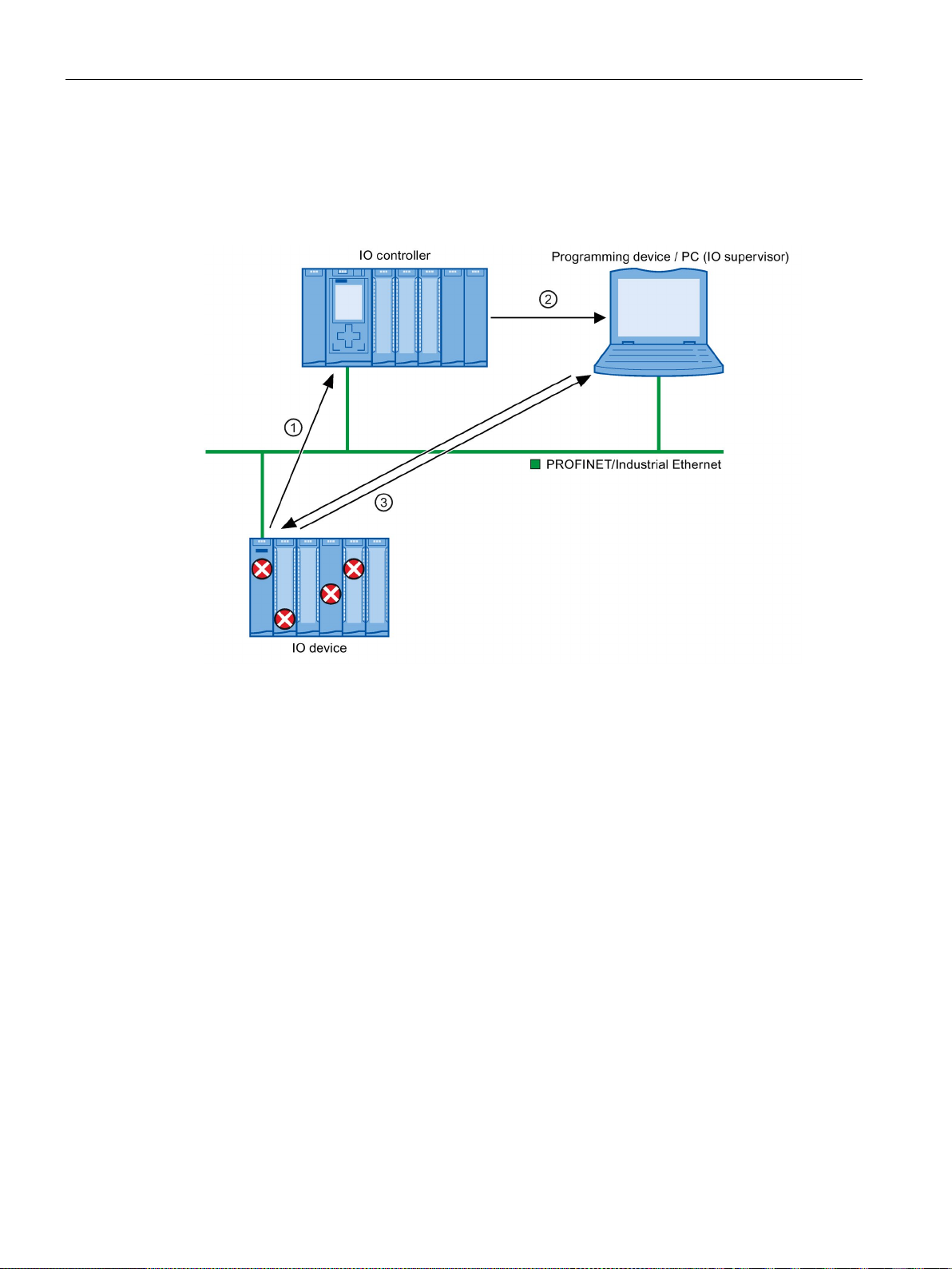
Diagnostics
Accessing the status of an IO device with a PG/PC or an HMI device
Number
Description
①
The IO device detects an error and sends diagnostics data to the IO controller.
②
is updated.
③
7, you can read the station status for "Accessible devices" directly from the IO device
regardless of the IO controller. This is only possible if the programming device is connected to
for servicing even if the IO controller is not operational.
4.1 Diagnostics mechanisms of PROFINET IO
If you are connected to the Industrial Ethernet via a PG/PC with STEP 7 or an HMI device,
you can also call up diagnostics information online. This is illustrated by the following
graphic.
The IO controller notifies the programming/HMI device. The display of the system diagnostics
In STEP
Industrial Ethernet.
This means that you can access diagnostics information during the commissioning phase or
Figure 4-1 PROFINET IO diagnostics with PG/PC or HMI device
PROFINET with STEP 7 V14
70 Function Manual, 09/2016, A5E03444486-AG
Page 71
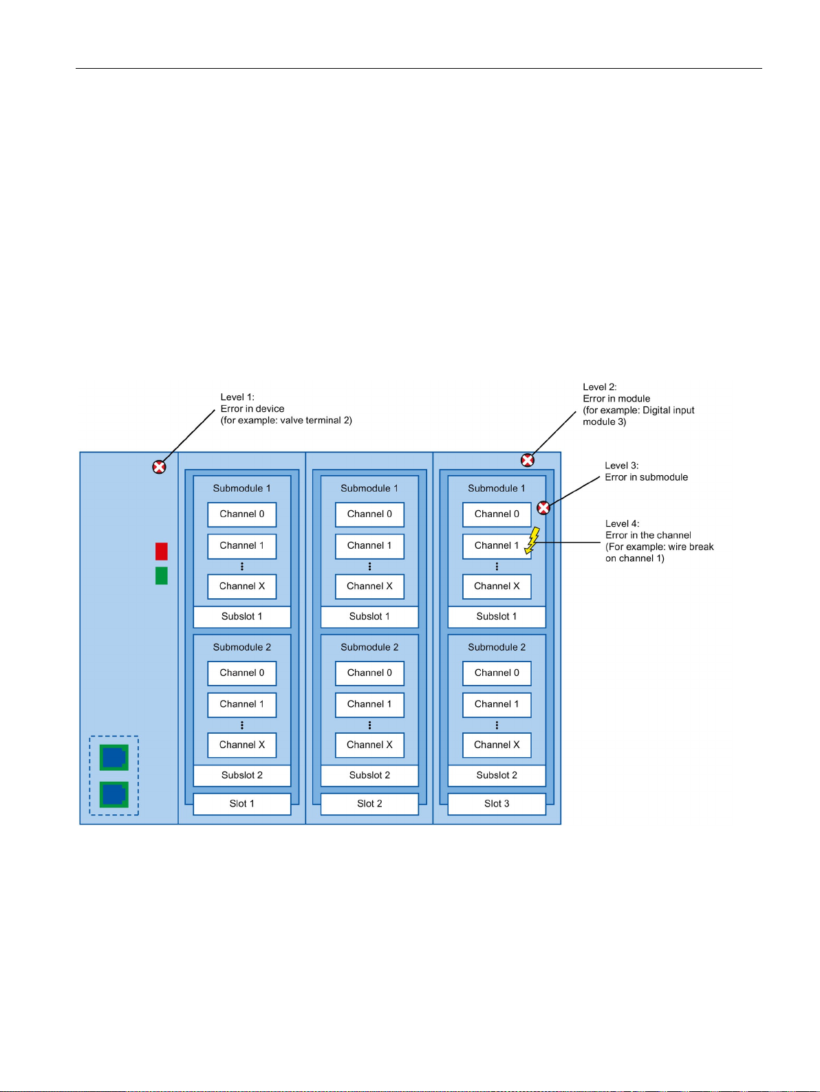
Diagnostics
4.1.1
Diagnostics levels in PROFINET IO
Concept
Diagnostics levels
4.1 Diagnostics mechanisms of PROFINET IO
The IO device sends all error messages that occur to the IO controller. The scope and
volume of diagnostics information varies according to the level of diagnostics data evaluation
and the PROFINET devices you are using.
You can evaluate diagnostics data at different levels. The number and type of channels is
selected, for example, at the diagnostics level 4.
The following figure shows the diagnostics levels with PROFINET IO.
Figure 4-2 Diagnostics levels with PROFINET IO
PROFINET with STEP 7 V14
Function Manual, 09/2016, A5E03444486-AG
71
Page 72
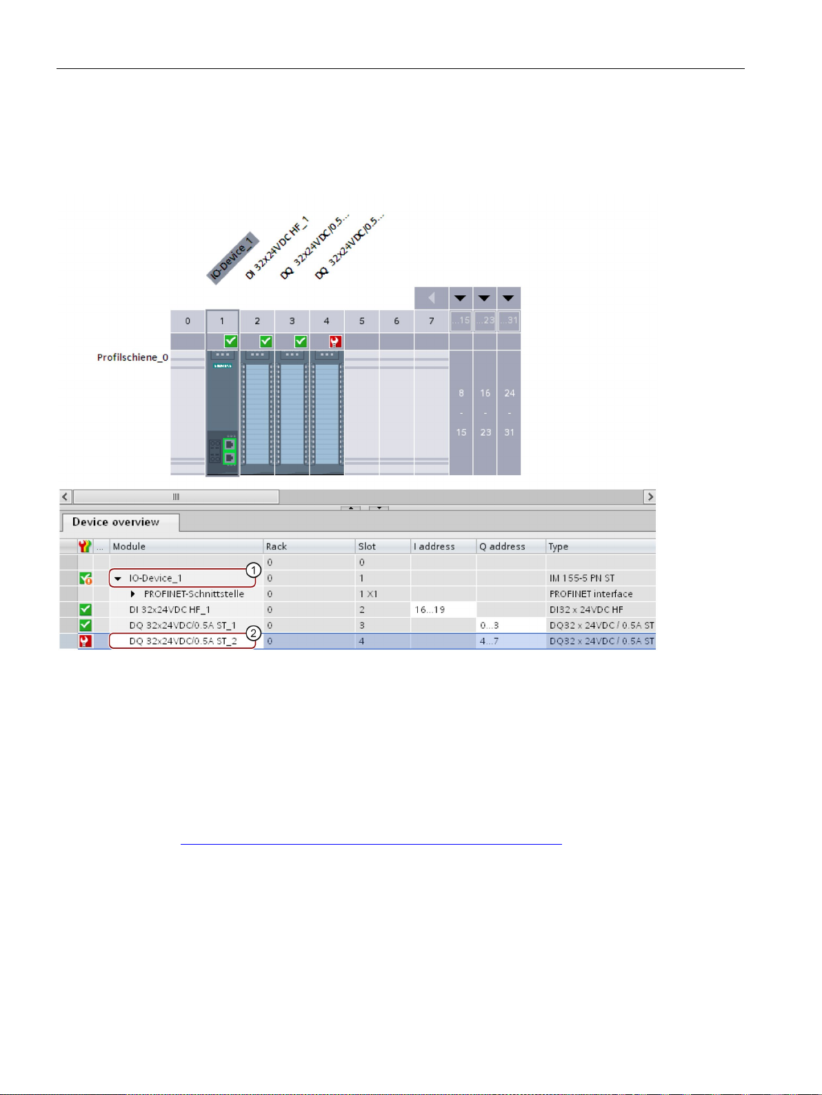
Diagnostics
Representation of diagnostics levels in the device view in STEP 7
Number
Description
①
Level 1:
Error(s) in the device
②
Level 2:
Error(s) in the module
Which PROFINET nodes support the extended PROFINET diagnostics?
4.1 Diagnostics mechanisms of PROFINET IO
The following figure shows the representation of the PROFINET device model in the device
view of STEP 7, based on the example of a distributed I/O system ET 200MP:
Figure 4-3 Diagnostics levels in the device view of STEP 7
An overview of the PROFINET nodes that support extended PROFINET diagnostics and of
what you have to configure is provided in this FAQ
(https://support.industry.siemens.com/cs/ww/en/view/23678970
PROFINET with STEP 7 V14
72 Function Manual, 09/2016, A5E03444486-AG
).
Page 73

Diagnostics
4.1.2
I&M data (identification and maintenance)
Definition and properties
Further information
4.1.3
Loading I&M data to PROFINET IO devices and your modules
Which I&M data can be loaded to PROFINET IO devices and your modules?
Requirements
4.1 Diagnostics mechanisms of PROFINET IO
Identification and maintenance data (I&M) is information saved to module memory in order to
provide support when:
● Checking the plant configuration
● Locating hardware changes in a plant
Identification data (I data) is module information (some of which may be printed on the
module housing) such as the order and serial number. I data is read-only vendor-specific
module data.
Maintenance data (M data) is plant-specific information such as the location identifier and
installation date. M data is created during configuration.
The modules can be uniquely identified in online mode by means of the I&M data.
To find out whether and to what extent a PROFINET device supports I&M data, refer to the
documentation of the relevant device.
You can load I&M 1 data (plant designation and location identifier) and/or I&M 2 data
(installation date) and/or I&M 3 data (additional information) to the actual hardware.
● In the project settings (Options > Settings, Hardware configuration > Compiling and
downloading), the option "Download I&M data" must be enabled.
● There is an online connection to the PROFINET IO devices and the modules to which you
want to load I&M data.
● You have entered the I&M data you want to download in the properties of the respective
PROFINET IO devices and your modules (Inspector window: "Properties" tab > "General"
tab, Settings > Identification & Maintenance).
PROFINET with STEP 7 V14
Function Manual, 09/2016, A5E03444486-AG
73
Page 74

Diagnostics
Where do I specify which I&M data is downloaded to which PROFINET IO devices?
Note
Language dependency of the I&M data to be loaded
The I&M data are loaded to the real hardware in the form that you specified in the properties
of the relevant PROFINET IO devices and your modules. There is no language dependency.
4.1 Diagnostics mechanisms of PROFINET IO
You specify which I&M data you want to download to which PROFINET IO devices in the
"Load preview" dialog. You will find the following alternatives in the drop-down list of the
"Identification and maintenance data (I&M)" row:
● Load nothing
The check boxes for all PROFINET IO devices as well as the check boxes for the
loadable I&M data are cleared.
No I&M data is transferred to the actual hardware during loading with this setting.
● Load data
The check boxes for all PROFINET IO devices as well as the check boxes for the
loadable I&M data are selected.
The respective I&M 1, I&M 2 and I&M 3 data is transferred to all PROFINET IO devices
during loading with this setting.
● Load selected
You select the check boxes of those PROFINET IO devices to which you want to load
I&M data. You also select the check boxes of the identification data you want to load.
With this setting, you transfer the selected I&M data to the selected PROFINET IO
devices during loading.
PROFINET with STEP 7 V14
74 Function Manual, 09/2016, A5E03444486-AG
Page 75

Diagnostics
4.2
Diagnostics using status LEDs
LEDs for diagnostics on PROFINET
Meaning
LED image
S7-1500
ET 200MP
ET 200SP
ET 200AL
LINK/TX/RX LED
LK LED
P1 Link
LED
P2 Link
LED
example, IO controller).
LED flashes green
LED yellow
Additional information
4.2 Diagnostics using status LEDs
Each port of a PROFINET interface of a SIMATIC device has one LED.
The following table shows a summary of the meaning of these LEDs in the S7-1500,
ET 200MP, ET 200SP and ET 200AL systems.
Table 4- 1 S7-1500, ET 200MP, ET 200SP, ET 200AL: LEDs for diagnostics on PROFINET
There is no connection between the
PROFINET interface of your PROFINET
device and a communication partner (for
example, IO controller).
There is a connection between the
PROFINET interface of your PROFINET
device and a communication partner (for
The "Node flash test" is performed.
There is active data traffic (sending/receiving) via the Ethernet connection.
You can find a detailed description of all LEDs of the module with cause of the error and
remedies in the relevant documentation for the module.
LED off
LED green
X X X X
X X X X
X X X X
X X - -
PROFINET with STEP 7 V14
Function Manual, 09/2016, A5E03444486-AG
75
Page 76
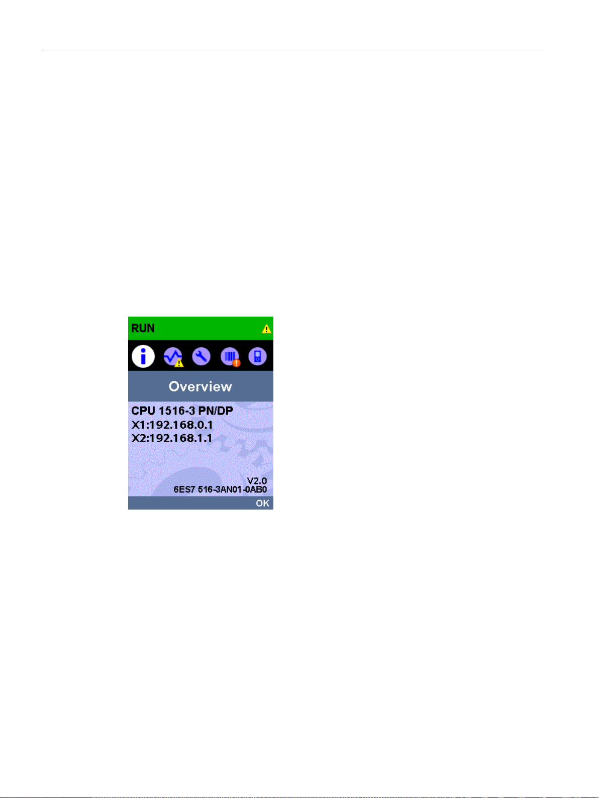
Diagnostics
4.3
Diagnostics via the display of the S7-1500 CPUs
Display of the S7-1500 CPUs
Diagnostics via the display
4.3 Diagnostics via the display of the S7-1500 CPUs
Each CPU in the S7-1500 automation system has a front cover with a display. Control and
status information is shown in various menus on the display. You use the operating keys to
navigate through the menus.
The following indicators can be evaluated for diagnostics purposes on the display:
● Error and alarm texts (system diagnostics, alarm messages)
● Module status for central and distributed modules
In the following example of a display of the CPU 1516-3 PN/DP, you can see a warning on
the diagnostics icon and an exclamation mark on the icon for module.
Figure 4-4 Display of overview
PROFINET with STEP 7 V14
76 Function Manual, 09/2016, A5E03444486-AG
Page 77
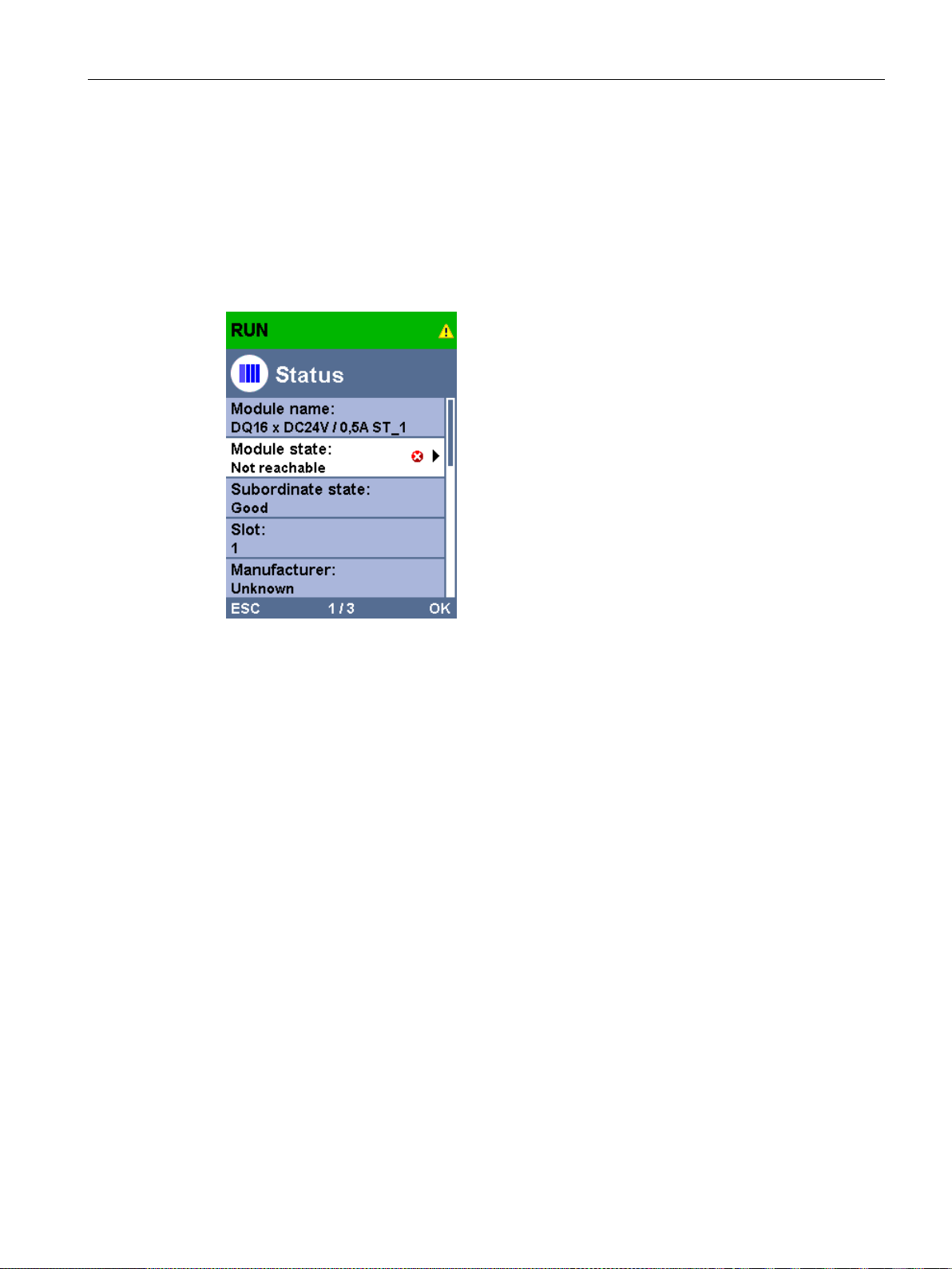
Diagnostics
Module status
4.3 Diagnostics via the display of the S7-1500 CPUs
To show the module status, navigate on the display through the menu items "Module" >
"PROFINET I/O (X1)" > "Station" > "Slot" > "Status" > "Module status".
The module status indicates that a fault has occurred in the module. The "lower-level status"
is the status of the module in the diagnostics level below this. In the example, the status is
"good", i.e., the fault is not in the lower diagnostics level submodule or channel, but instead
in the module.
Figure 4-5 Display of module status
PROFINET with STEP 7 V14
Function Manual, 09/2016, A5E03444486-AG
77
Page 78
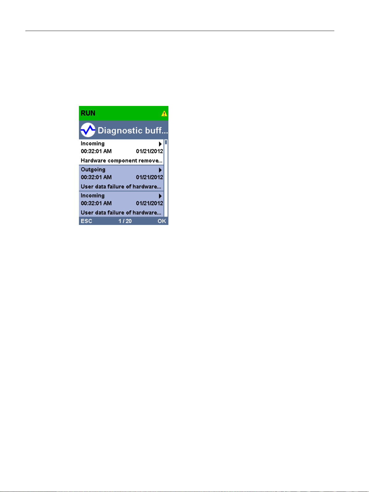
Diagnostics
Error and alarm texts
4.3 Diagnostics via the display of the S7-1500 CPUs
You can show diagnostics buffer entries and alarm messages for the relevant automation
system on the display.
To show the diagnostics buffer entries of the CPU, navigate on the display via the menu
items "Diagnostics" > "Diagnostics buffer".
Figure 4-6 Display of diagnostics buffer
To show the alarm messages of the automation system, navigate through the menu items
"Diagnostics" > "Alarms" > "Alarm text" on the display.
PROFINET with STEP 7 V14
78 Function Manual, 09/2016, A5E03444486-AG
Page 79
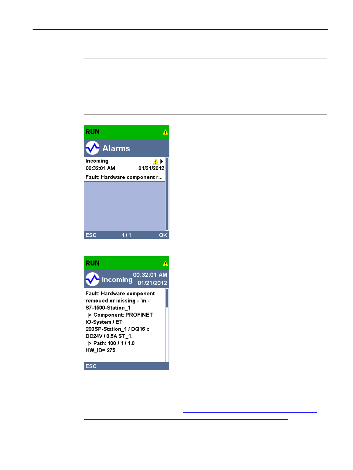
Diagnostics
Note
Updating the alarm display
The display shows the currently read status of the CPU in static form, the display is not
automatically updated. The alarm display is updated after it has been exited and opened
again.
You set the automatic updating of the diagnostics information under: "
"DiagnosticRefresh".
Additional information
4.3 Diagnostics via the display of the S7-1500 CPUs
Display" >
Figure 4-7 Display of alarms
Figure 4-8 Display of alarm message
You can find the description of the operation and functions of the display in the
SIMATIC S7-1500 Display Simulator (
as/interactive-manuals/getting-started_simatic-s7-1500/disp_tool/start_de.html).
PROFINET with STEP 7 V14
Function Manual, 09/2016, A5E03444486-AG
http://www.automation.siemens.com/salesmaterial-
79
Page 80
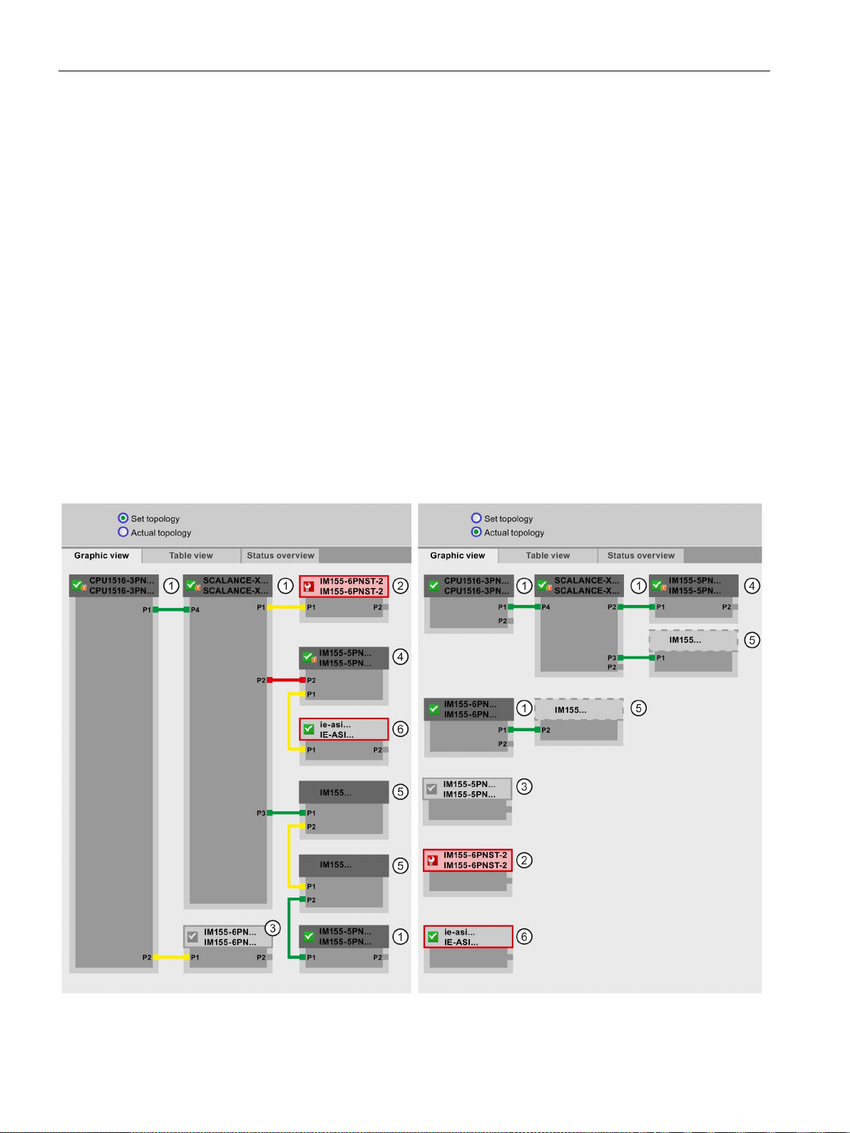
Diagnostics
4.4
Diagnostics via Web server
Set topology and actual topology - graphic view
4.4 Diagnostics via Web server
The CPUs belonging to the S7 family have their own integrated Web server with a wide
range of functions.
For diagnostics, the Web server supports you with the following displays:
● Contents of the diagnostic buffer
● Module status
● Actual topology of the PROFINET system
● Set topology of the PROFINET system (from the configuration)
Requirements for displaying the set and actual topology:
● You have configured the PROFINET ports in the topology editor of the hardware and
network editor of STEP 7.
● You have loaded the entire project with STEP 7 in the CPU.
The following shows an example of the graphic view.
Figure 4-9 Topology - graphic view via the Web server
PROFINET with STEP 7 V14
80 Function Manual, 09/2016, A5E03444486-AG
Page 81

Diagnostics
Connection
Meaning
Set topology
Actual topology
connection (e.g., port interchanged).
① Configured and accessible PROFINET devices
① Configured but not accessible PROFINET devices
③ Disabled devices
④ Interchanged ports
4.4 Diagnostics via Web server
Meaning of the colored connections in the set/actual topology:
Table 4- 2 Meaning of the colored connections in the set/actual topology:
green The current actual connection matches the configured set connec-
tion.
red The current actual connection does not match the configured set
yellow The connection cannot be diagnosed. Causes:
• The communication to an IO device has been disrupted (e.g.,
cable removed)
• Connection to a passive component
• Connection to PROFINET devices of another IO controller or
PROFINET system
Configured and accessible PROFINET devices are displayed dark-gray. Connections show
the ports through which the PROFINET devices of a station are connected.
The configured but not accessible PROFINET devices are displayed in pink with red border
(e.g., device has failed, cable disconnected).
detected connections
-
-
All disabled, configured PROFINET devices are displayed light-gray.
Interchanged ports are marked red in the set topology view. The currently connected ports
are displayed in the actual topology, the configured set connection in the set topology.
PROFINET with STEP 7 V14
Function Manual, 09/2016, A5E03444486-AG
81
Page 82

Diagnostics
⑤ PROFINET devices of another PROFINET IO system
⑥ Representation of faulty neighbor relations
Additional information
4.4 Diagnostics via Web server
● In the set topology:
A PROFINET device of another PROFINET IO system is displayed with a green
connection (or red connected if the ports have been interchanged), when it is directly
adjoining a configured and accessible PROFINET device
When the PROFINET device of another PROFINET IO system is not accessible, a yellow
connection line is displayed.
The connection between two PROFINET devices that both belong to a different
PROFINET IO system, cannot be determined and is always displayed in yellow.
● In the actual topology:
A PROFINET device of another PROFINET IO system is only displayed if the PROFINET
device is in direct proximity to a configured PROFINET device. The PROFINET device is
displayed light-gray and with dashed line.
For PROFINET devices of a different PROFINET IO system, no status display is shown on
the device head.
① and it is also accessible.
The devices whose neighbor relations cannot be read out completely or correctly are
displayed light-gray with red border.
The tabular view of the actual topology and the status overview of the PROFINET devices in
the project are possible.
You can find these views, additional topology examples, and detailed information on the
operation and the functions of the Web server in the Web server
(http://support.automation.siemens.com/WW/view/en/59193560
) manual.
PROFINET with STEP 7 V14
82 Function Manual, 09/2016, A5E03444486-AG
Page 83
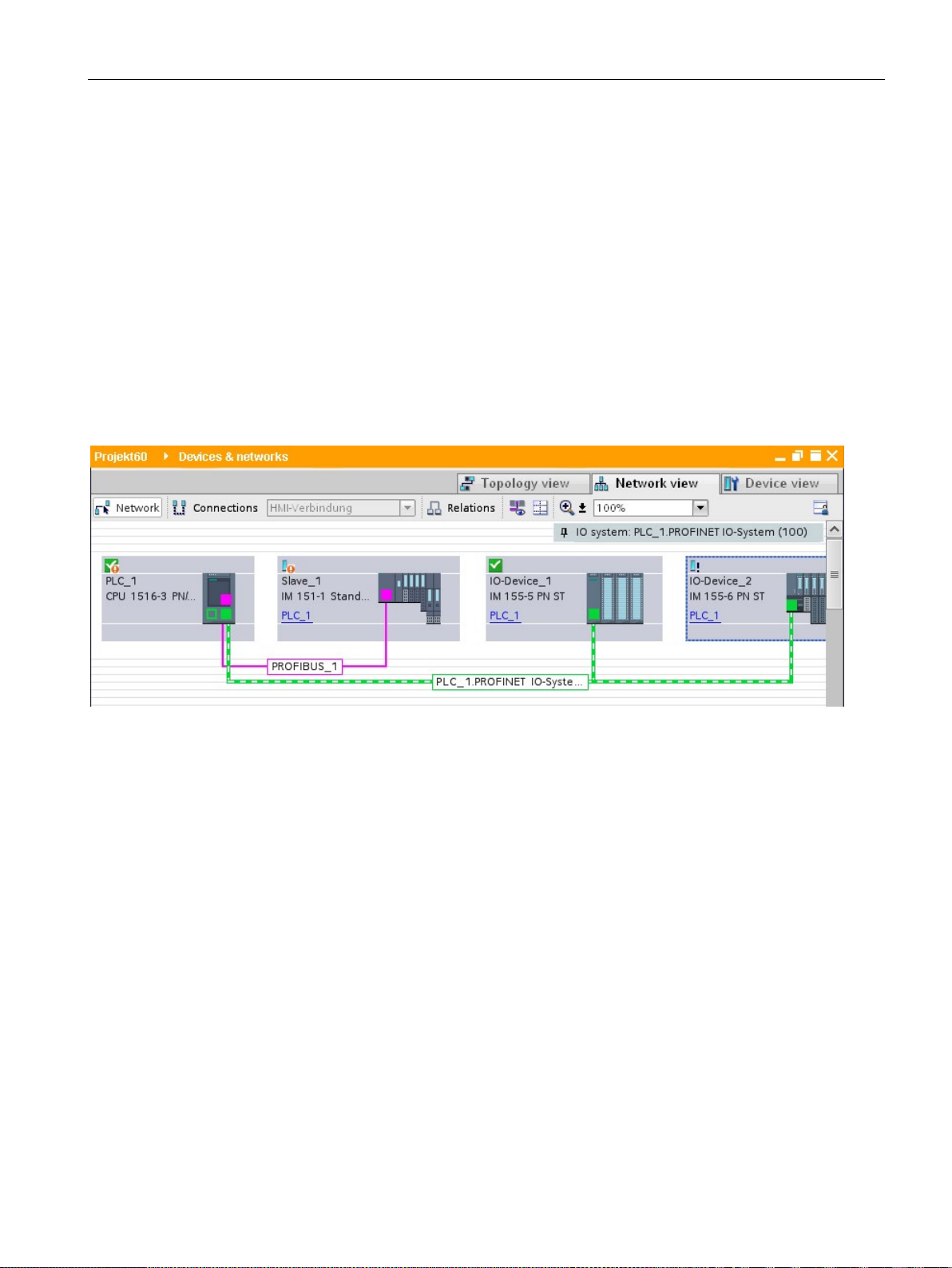
Diagnostics
4.5
Diagnostics in STEP 7
Online & diagnostics network view
4.5 Diagnostics in STEP 7
For PROFINET, you have the following options to evaluate diagnostics in STEP 7:
● Online & diagnostics - Devices & networks
● Online & diagnostics - diagnostics of PROFINET ports
In the hardware and network editor (launched from the "Project tree" by double-clicking
"Devices & networks"), you can get an overview of the current state of your system by
clicking on the "Go online" button. It also shows the configuration information (for example,
non-configured modules). This option is also available in the topology view in similar form.
Schematic drawing of the network view (online):
Figure 4-10 Online & diagnostics network view
PROFINET with STEP 7 V14
Function Manual, 09/2016, A5E03444486-AG
83
Page 84
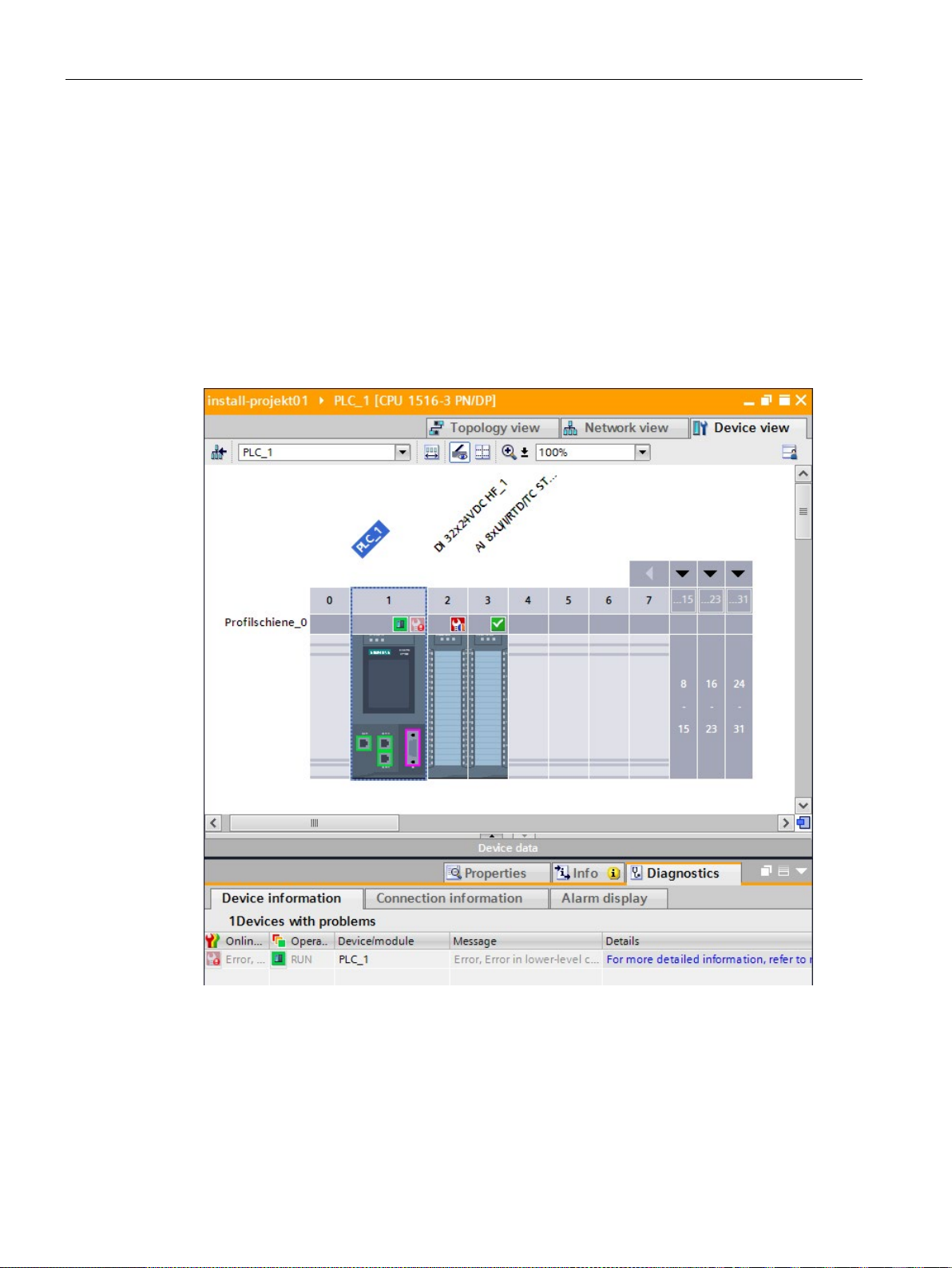
Diagnostics
Online & diagnostics device view
4.5 Diagnostics in STEP 7
In STEP 7, you can display an overview of the modules in which faults have occurred. To do
this, select the menu command "Online > Online & diagnostics". Once you are connected,
you can see the status of the accessible devices in the project tree.
Double-click the device which displays an alarm message to access the faulty module
directly. The device view is opened in the work area. In the device view of the device that
reports the fault you can see directly in which module the fault occurs.
Open the "Diagnostics" tab and the subordinate "Device information" tab in the Inspector
window for a more detailed error description.
Schematic drawing of the device view (online):
Figure 4-11 Online & diagnostics device view
PROFINET with STEP 7 V14
84 Function Manual, 09/2016, A5E03444486-AG
Page 85
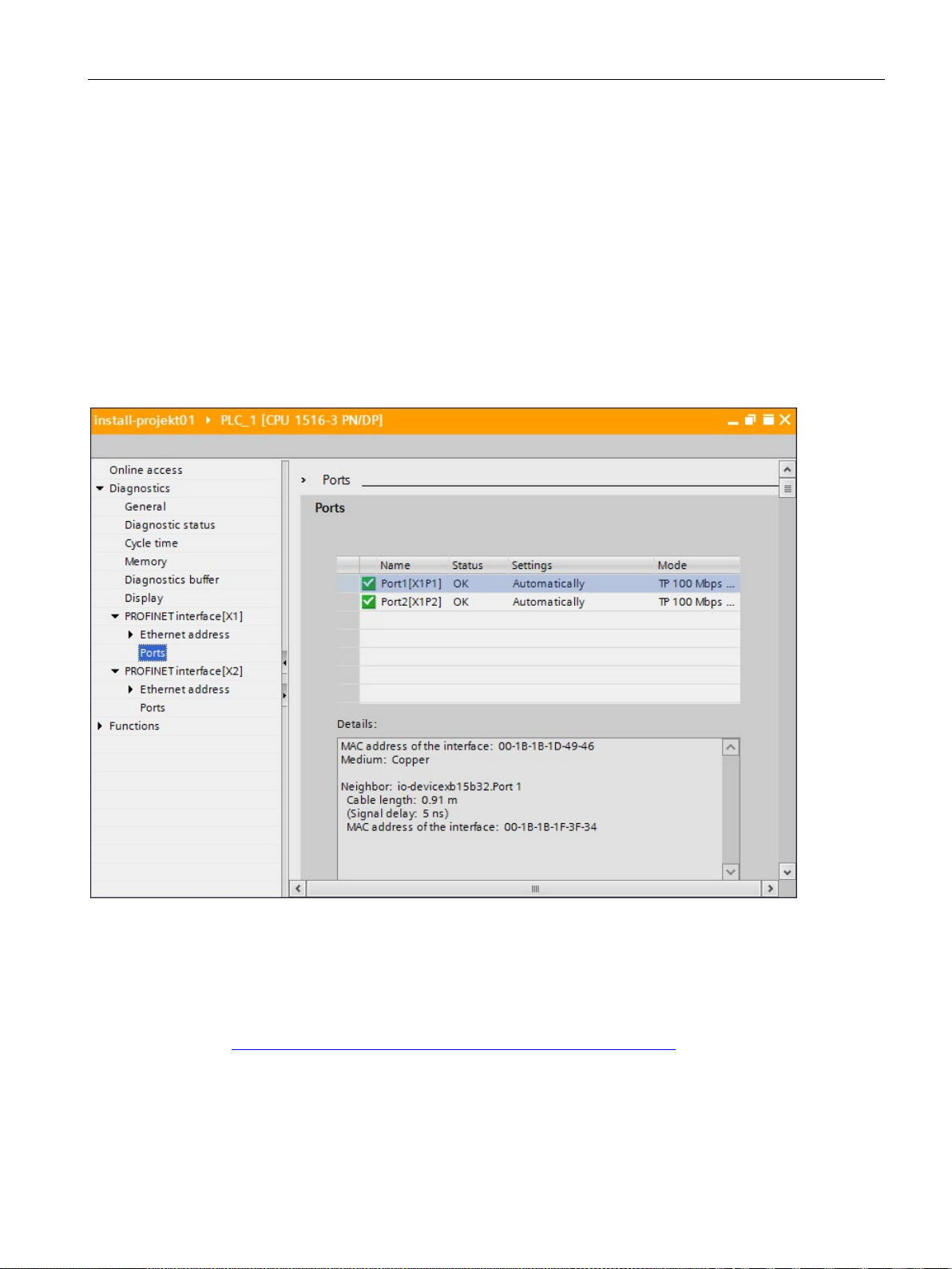
Diagnostics
Diagnostics of PROFINET ports
Additional information
4.5 Diagnostics in STEP 7
If you select "PROFINET interface > Ports" in the Diagnostics area in the online &
diagnostics device view of a PROFINET device, the ports of the PROFINET interface are
listed in a table.
The table provides you with the following information about the ports of the PROFINET
interface.
● Name
● Status
● Settings
● Operating mode
Figure 4-12 Diagnostics of PROFINET ports in STEP 7
You can find information on the system diagnostics for S7-1500, ET 200MP, ET 200SP and
ET 200AL in the Diagnostics
(http://support.automation.siemens.com/WW/view/en/59192926
help for STEP 7.
PROFINET with STEP 7 V14
Function Manual, 09/2016, A5E03444486-AG
) function manual and online
85
Page 86
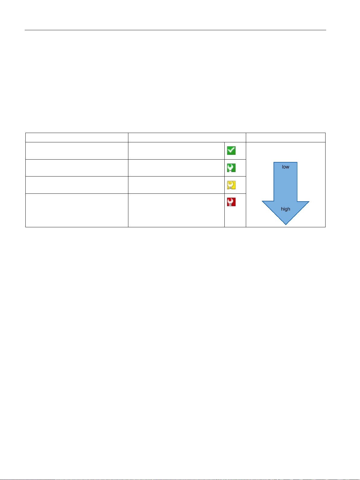
Diagnostics
4.6
Extended maintenance concept
Extended maintenance concept
Diagnostic status
Symbol
Severity of the error
demanded
4.6 Extended maintenance concept
The PROFINET interfaces with integrated switch of the SIMATIC devices support the fourlevel diagnostics concept in accordance with PROFINET specification Version V2.3 or higher
with the following status:
Table 4- 3 Classification of the diagnostic status
Good
Maintenance
required
Maintenance
Bad
Green checkmark
Green wrench
Yellow wrench
Red wrench
The aim of the diagnostics concept is the early detection and elimination of potential faults before they cause a production outage.
Other status information is defined in addition to the Good (no fault) and Bad (fault) status
information for a PROFINET device.
The maintenance information is generated with the following system alarms:
● Maintenance required (symbolized by a green wrench) and
● Maintenance demanded (symbolized by a yellow wrench)
The times at which the two system alarms are generated can be customized for most wear
parameters.
PROFINET with STEP 7 V14
86 Function Manual, 09/2016, A5E03444486-AG
Page 87
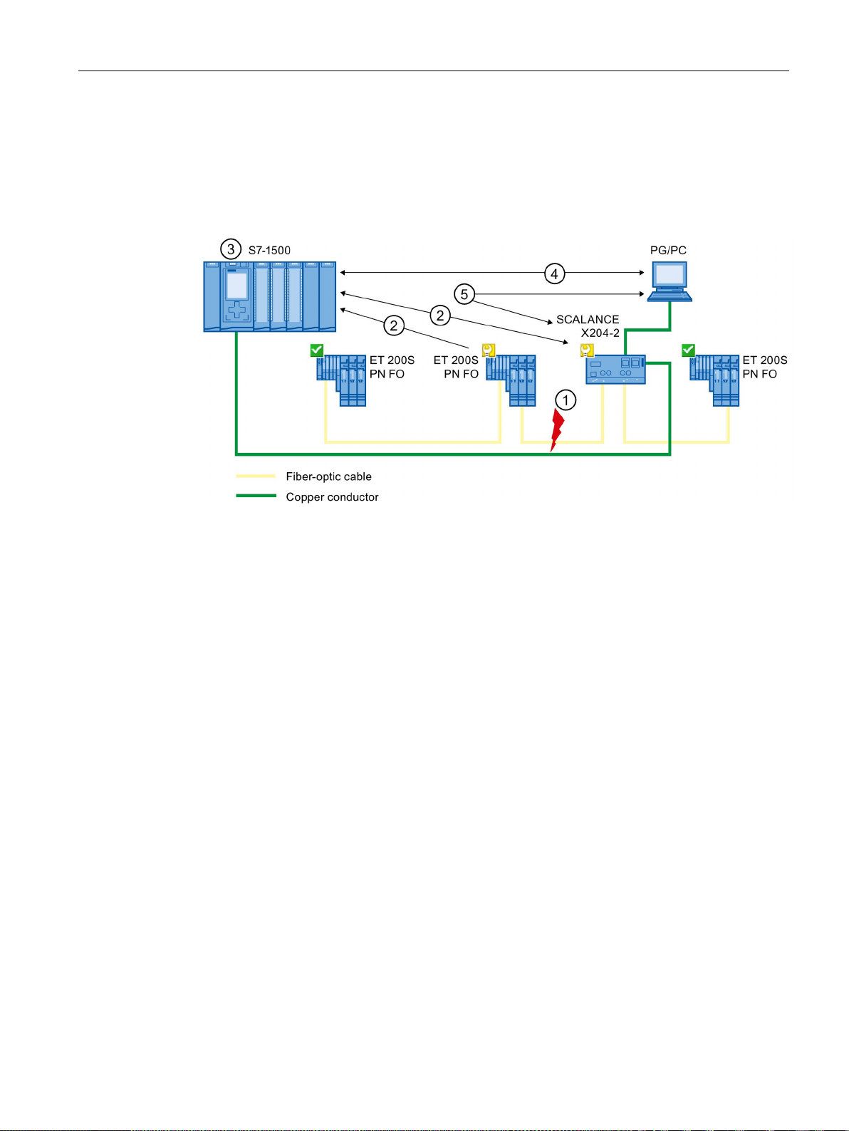
Diagnostics
Example: Maintenance demanded for a PROFINET cable
Number
Description
①
The system reserve of the fiber-optic cable drops below 0 dB.
②
controller.
③
Based on the interrupts, the IO controller detects the maintenance demanded from the switch
STEP 7 for the relevant IO controller.
④
cated on the IO device and at the switch by a yellow wrench symbol.
⑤
STEP 7 can also read out detailed information directly from the switch.
4.6 Extended maintenance concept
The following graphic illustrates how diagnostics information is exchanged when the
transmission quality on the optical cable decreases due to ageing, for example. In this
example, the scenario is considered after a maintenance required has already been
diagnosed.
Both the ET 200S PN FO and the switch send the maintenance demanded alarm to the IO
and from the IO device. The module information data is updated in the IO controller and the
corresponding error OBs are called. Note: To be able to start the error OBs in the IO controller, the "Call the user program if communication errors occur" property must be selected in
In STEP 7 (on the programming device/PC), the maintenance demanded message is indi-
Figure 4-13 Maintenance demanded for a PROFINET cable
PROFINET with STEP 7 V14
Function Manual, 09/2016, A5E03444486-AG
87
Page 88

Diagnostics
4.7
Diagnostics of the network topology
Availability
Network diagnostics
MIB
MIB
Detecting the network topology
Use of SNMP (Simple Network Management Protocol)
Use of SNMP in the SIMATIC NET environment
4.7 Diagnostics of the network topology
As an open standard, you can use any SNMP based systems or software solutions for
diagnostics in PROFINET.
The network management protocol SNMP (Simple Network Management Protocol) uses the
wireless UDP transport protocol. It consists of two network components, similar to the
client/server model. The SNMP manager monitors the network nodes and the SNMP clients
collect the various network-specific information in the individual network nodes and store it in
a structured form in the
network management system to run detailed network diagnostics.
(Management Information Base). This information allows a
The MIB (Management Information Base) is the database of a device. SNMP clients access
this database in the device. The S7 device family supports the following standard MIBs:
● MIB II, standardized in the RFC 1213
● LLDP-MIB, standardized in the international standard IEC 802.1AB
● LLDP-PNIO-MIB, standardized in the international standard IEC 61158-6-10
LLDP (Link Layer Discovery Protocol) is a protocol that is used to detect the closest
neighbor. LLDP enables a device to send information about itself and to receive information
from its neighbor devices. This information is then saved in the LLDP MIB, for example, and
can be queried using SNMP. This information allows a network management system to
determine the network topology.
SNMP can be used as follows:
● By users to integrate network diagnostics into a central HMI/SCADA system using the
SIMATIC NET OPC server
● By the IT administration of machine and plant operators to monitor their Industrial
Ethernet network using standard network management systems.
● By the IT administration, to monitor the automation network, alongside the office network,
using standard network management systems.
SNMP-compliant devices from the SIMATIC NET family can be monitored and operated via
a conventional standard Internet browser. The management system known as web-based
management offers a wide range of device-specific information (network statistics, status of
redundant supply, for example).
PROFINET with STEP 7 V14
88 Function Manual, 09/2016, A5E03444486-AG
Page 89

Diagnostics
4.8
Diagnostics in the user program
4.8.1
Diagnostics and configuration data records
Diagnostics mechanism
Diagnostics data records in PROFINET IO
Addressing levels of diagnostics data records
4.8 Diagnostics in the user program
The IO device outputs a diagnostics interrupt to the IO controller when it detects faults such
as wire break on an IO module. This interrupt calls a corresponding organization block in the
user program (diagnostics interrupt OB82), in order to generate a defined (programmed)
response to the fault and passes a diagnostics data record.
There are two different types of diagnostics data record:
1. Channel diagnostics data records
Channel diagnostics data records are generated if a channel is in an error state and / or
has triggered an interrupt.
A diagnostics data record of length 0 is returned if there is no fault.
2. Vendor-specific diagnostics data records
The structure and size of vendor-specific diagnostics data records depend on the
vendor's settings.
For information about vendor-specific diagnostics data records, refer to the appropriate
device manual.
Diagnostics and configuration data is evaluated at the following addressing levels:
● Device level
● AR (Application Relation)
● API (Application Process Identifier)
● Slot
● Subslot
PROFINET with STEP 7 V14
Function Manual, 09/2016, A5E03444486-AG
89
Page 90
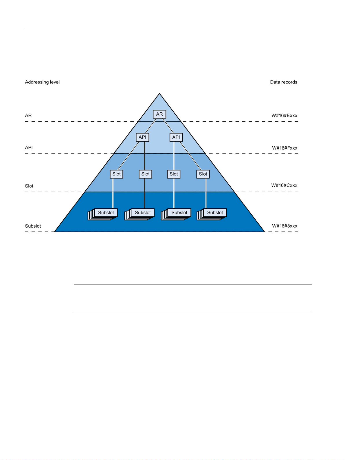
Diagnostics
Note
The diagnostics information is only generated for configured modules / submodules /
channels.
4.8 Diagnostics in the user program
A group of diagnostics and configuration data records are available for each address level
(exception: device level always 0xF80c). In HEX representation, the individual groups of data
records are distinguished by the first letter of the data record number.
Figure 4-14 Addressing levels of diagnostics data records
The information for each IO device (addressing level AR), module (addressing level slot) or
submodule (addressing level subslot) is always transferred in separate diagnostics or
configuration data records. The data record returns diagnostics data or configuration data for
one or more subslots, slots and APIs, depending on the addressing level.
PROFINET with STEP 7 V14
90 Function Manual, 09/2016, A5E03444486-AG
Page 91
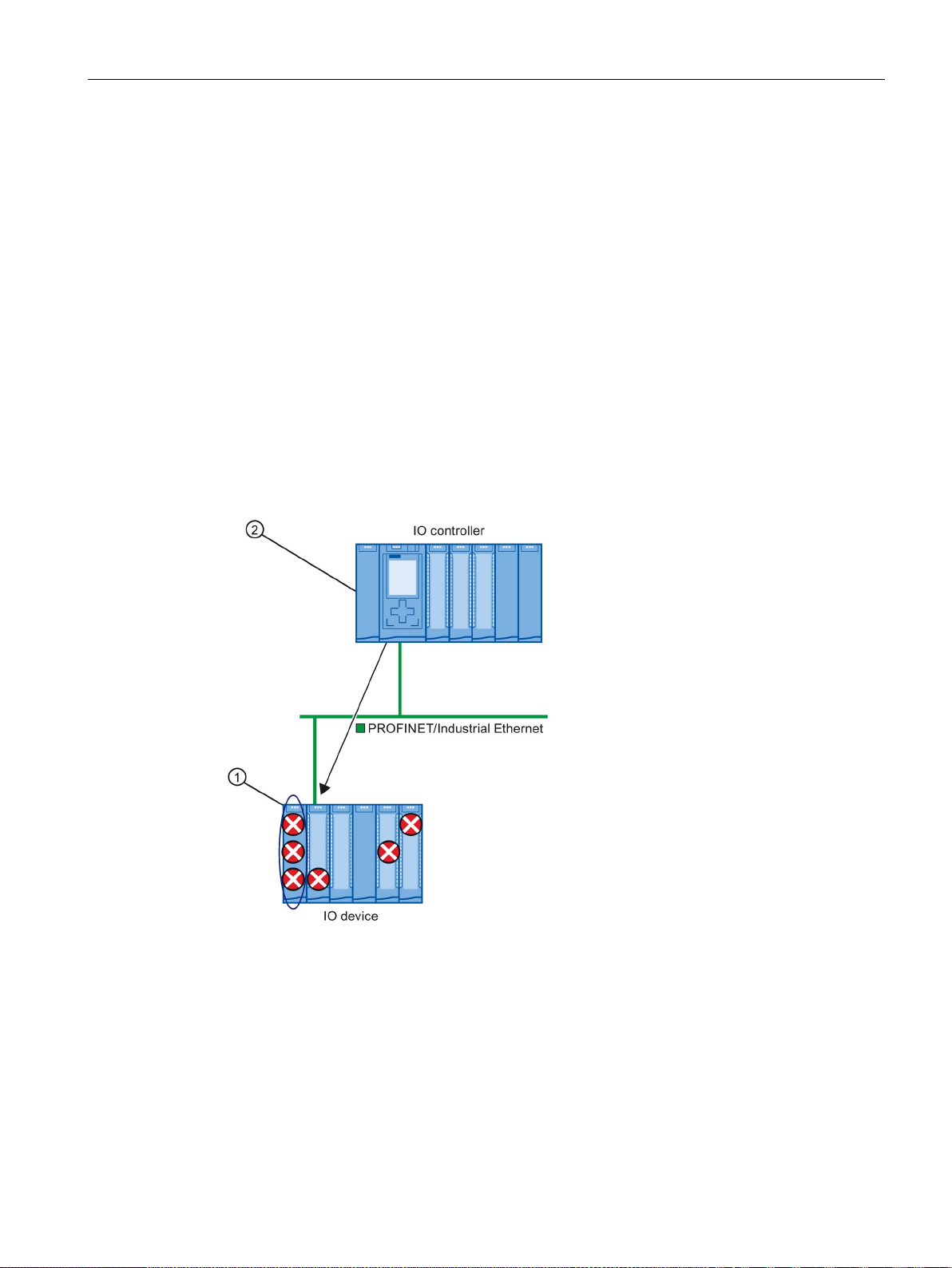
Diagnostics
4.8.2
Evaluate diagnostics in the user program
Diagnostics in the user program
1. Evaluating the diagnostics status
Number
Description
①
All individual errors are collected in a single data record on the interface module.
②
ly directly from the IO device.
4.8 Diagnostics in the user program
For PROFINET IO, a cross-vendor structure of data records with diagnostics information
applies. Diagnostics information is created only for channels on which a fault has occurred.
With PROFINET, there are two basic ways to obtain diagnostics information.
Read out the diagnostics of your PROFINET IO system using the instructions "DeviceStates"
and "ModuleStates", to localize those stations / modules or station / modules with
maintenance demanded or maintenance required that have faults within a PROFINET IO
system.
The instruction RDREC (read data record) is then used to read various diagnostics data
records directly from the module concerned and thus obtain detailed information about the
error.
In your user program, the instruction "RDREC" reads the entire station status asynchronous-
Figure 4-15 Example: Evaluating diagnostics data records with the instruction "RDREC"
PROFINET with STEP 7 V14
Function Manual, 09/2016, A5E03444486-AG
91
Page 92
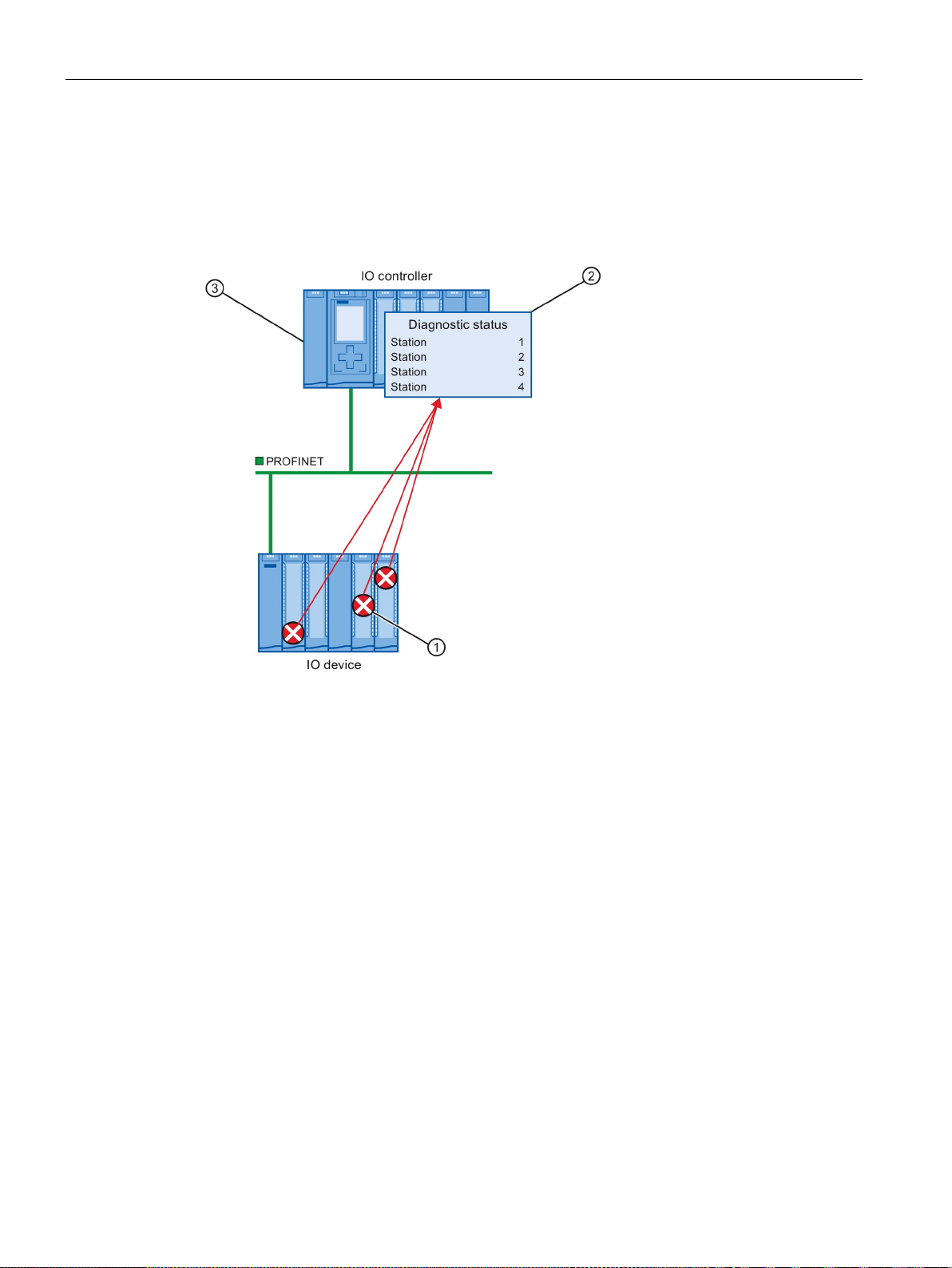
Diagnostics
2. Evaluation of interrupts
Number
Description
①
form of an interrupt.
②
(OB 82) is started.
③
chronously from the IO controller without addressing the IO device.
Instructions and OBs
4.8 Diagnostics in the user program
When the error OB (OB 82) is called, the OB's start information provides you with information
on the cause and location of the error. Detailed information on the error event can be
obtained in the error OB using the instruction "RALRM" (read additional interrupt
information).
Every error is sent to the IO controller individually as channel diagnostics information in the
In the IO controller, the module status data is updated automatically and the error OB
In your user program in the error OB (OB 82), the instruction "RALRM" reads the error syn-
Figure 4-16 Diagnostics with OB 82 and the instruction "RALRM"
You will find information on the instructions and OBs in the STEP 7 online help.
PROFINET with STEP 7 V14
92 Function Manual, 09/2016, A5E03444486-AG
Page 93

5
Introduction
The following section describes the PROFINET IO functions for field of application,
properties and configuration in STEP 7.
Refer to the documentation for the respective device to see to what extent the PROFINET
devices support the described functions.
You can find a tabular overview of the PROFINET devices and the functions these support
on the Internet (https://support.industry.siemens.com/cs/ww/en/view/102325771
).
PROFINET with STEP 7 V14
Function Manual, 09/2016, A5E03444486-AG
93
Page 94
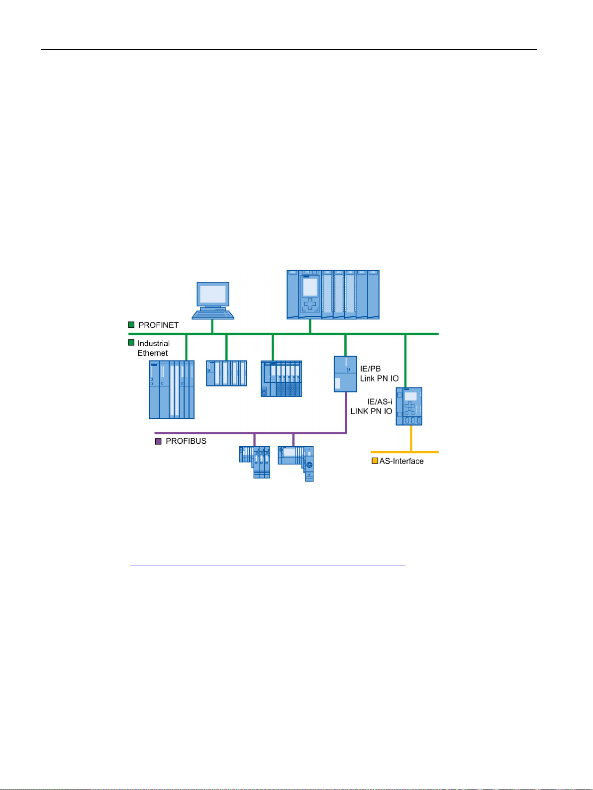
Functions
5.1
Connecting other bus systems
5.1.1
Connecting other bus systems
Fieldbus integration
Gateways of an S7-1500 CPU
5.1 Connecting other bus systems
PROFINET allows you to use a proxy-capable PROFINET device to integrate existing
fieldbus systems (for example, PROFIBUS, AS interface). The devices of these fieldbus
systems are mapped on proxy PROFINET devices. In this way, you can set up any hybrid
systems consisting of fieldbus and Ethernet-based subsystems. This allows a continuous
exchange of information.
Figure 5-1 Gateways on PROFINET IO
An overview of the gateways at an S7-1500 CPU is provided in this FAQ
(https://support.industry.siemens.com/cs/ww/en/view/88778900
PROFINET with STEP 7 V14
94 Function Manual, 09/2016, A5E03444486-AG
).
Page 95
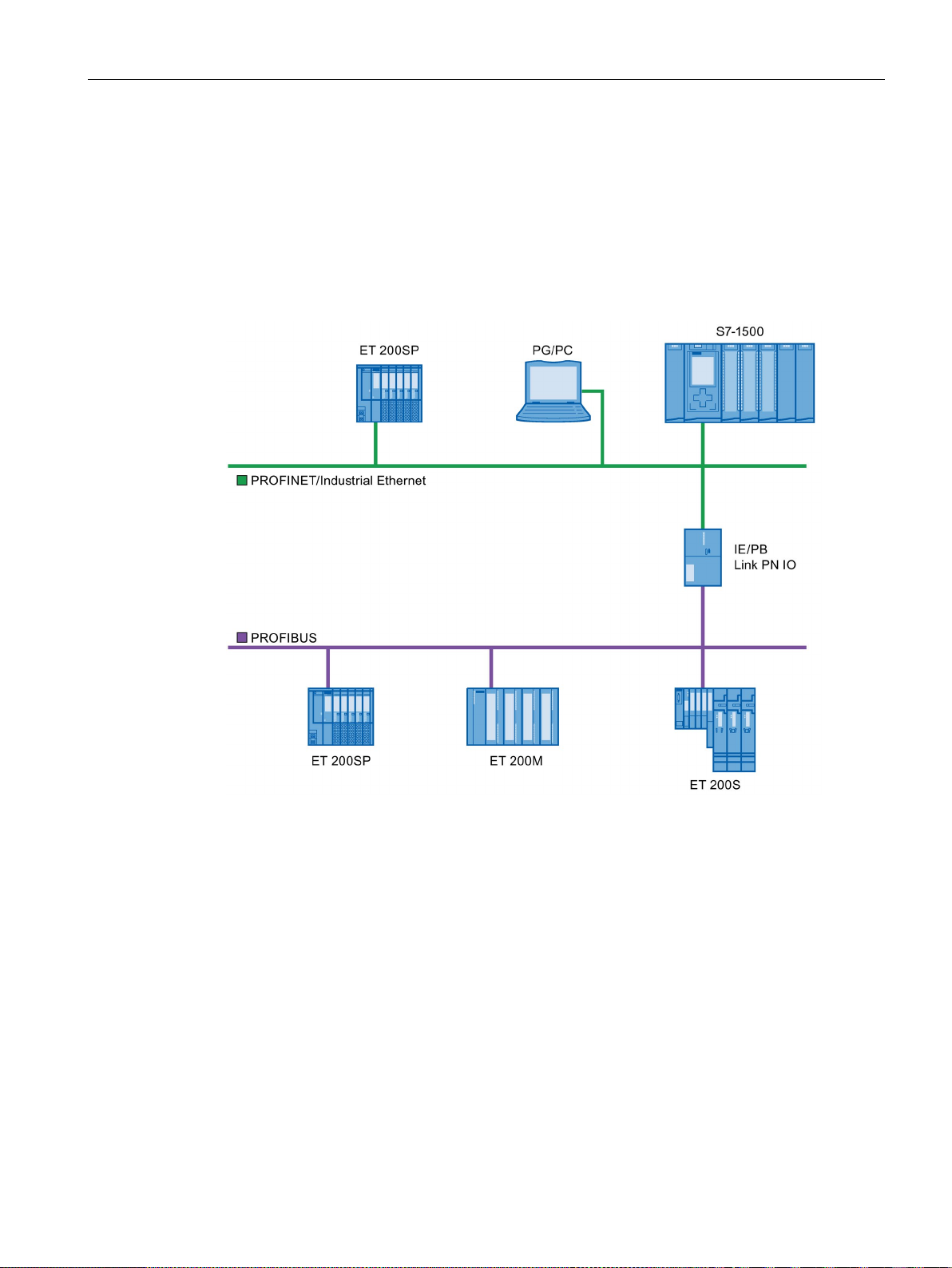
Functions
5.1.2
Linking PROFINET and PROFIBUS
Linking PROFINET and PROFIBUS
PROFINET device with proxy functionality
5.1 Connecting other bus systems
With a proxy-capable PROFINET device which is equipped with a PROFINET interface in
addition to a PROFIBUS interface (for example, IE/PB Link PN IO), you can integrate
existing PROFIBUS configurations into the PROFINET configuration.
The following figures shows how a PROFIBUS system is connected via IE/PB Link to a CPU
S7-1500 (as of firmware version 1.7).
Figure 5-2 Gateway from PROFINET and PROFIBUS via IE/PB link
The PROFINET device with proxy functionality is the substitute for a PROFIBUS device on
Ethernet. The proxy functionality allows a PROFIBUS device to communicate not only with
its master but also with all devices on PROFINET.
With PROFINET you can connect an existing PROFIBUS system to an IO controller, for
example with the help of an IE/PB Link PN IO.
From the IO controller perspective, the PROFIBUS DP slaves are connected to the same
network as the IE/PB Link PN IO. These slaves have the same device name and IP address
as the IE/PB Link PN IO, but different device numbers. Furthermore, each also has a specific
PROFIBUS address.
In this way, you can link both DPV0 and DPV1 slaves to PROFINET.
For information on how to connect a DP slave to a PROFINET IO system, refer to section
Connect the DP slave via the IE/PB Link to a PROFINET IO system (Page 96).
PROFINET with STEP 7 V14
Function Manual, 09/2016, A5E03444486-AG
95
Page 96
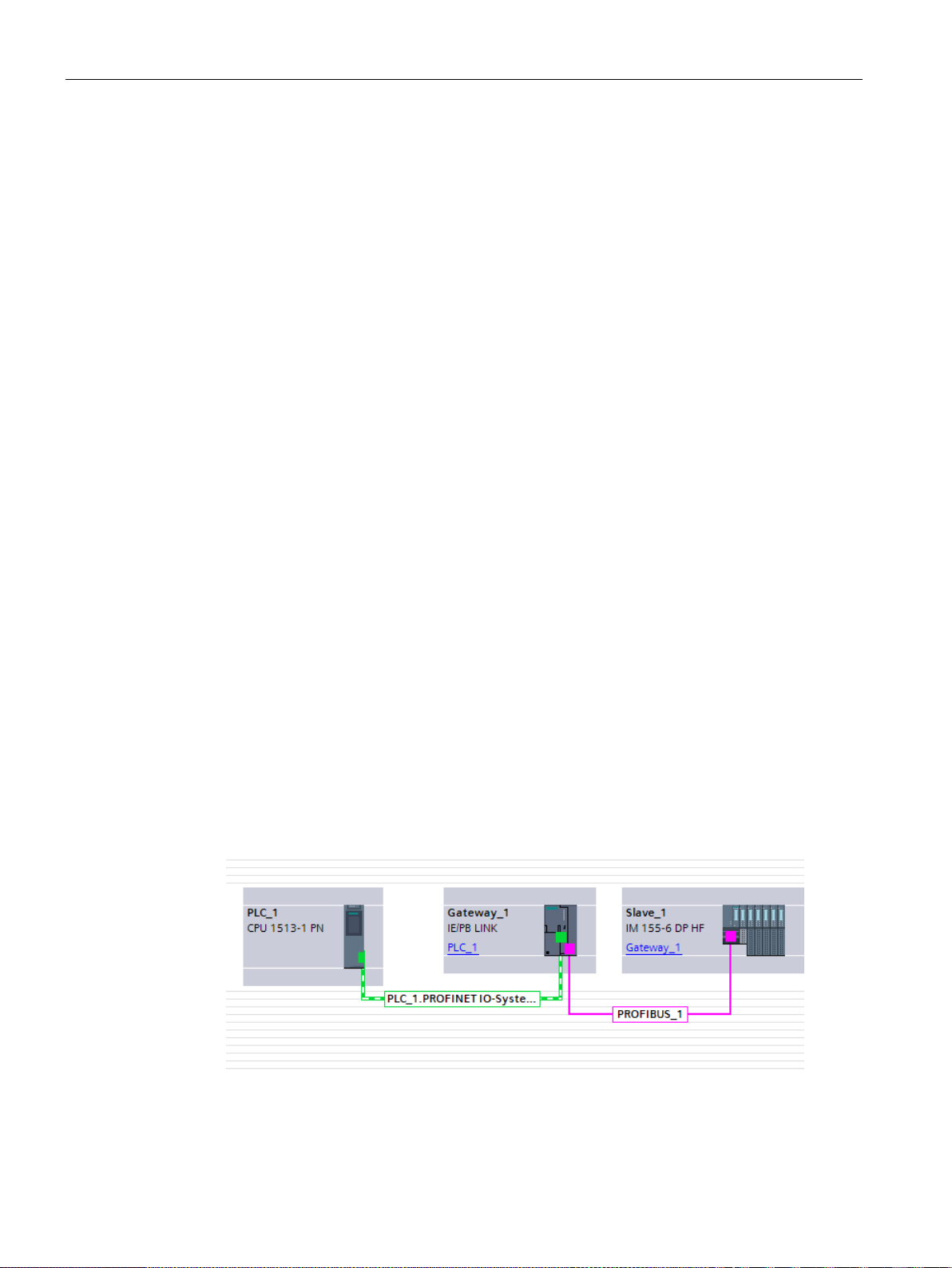
Functions
Diagnostic options with a CPU S7-1500 as IO controller
5.1.3
Connect the DP slave via the IE/PB Link to a PROFINET IO system
Requirements
Procedure for connecting a DP slave via an IE/PB Link
5.1 Connecting other bus systems
The CPU S7-1500 (as of firmware version 1.7) as IO controller detects disrupted DP slaves
behind the IP/PB link.
● STEP 7 as of V12
● S7-1500 CPU as of firmware version 1.7
● ET 200SP CPU as of firmware version 1.7
● CPU 1516pro-2 PN as of firmware version 2.0
● S7-1500 Software Controller as of firmware version 1.7
● S7-300/400 CPU
To connect a DP slave to a PROFINET IO system via an IE/PB Link in STEP 7, follow these
steps:
1. Drag-and-drop a PROFINET CPU, for example CPU 1513-1 PN, from the hardware
catalog into the network view of STEP 7.
2. Drag-and-drop an IE/PB Link PN IO from the hardware catalog into the network view of
STEP 7. The IE/PB Link PN IO is located under Network components > Gateways >
IE/PB Link PN IO.
3. Assign the IE/PB Link PN IO to the CPU.
4. Drag a PROFIBUS interface module e.g. IM155-6 DP HF, from the hardware catalog to
the network view.
5. Assign the interface module to the IE/PB Link.
Figure 5-3 Configuring an IE/PB link
6. Select the IE/PB Link PN IO in the network view of STEP 7.
PROFINET with STEP 7 V14
96 Function Manual, 09/2016, A5E03444486-AG
Page 97
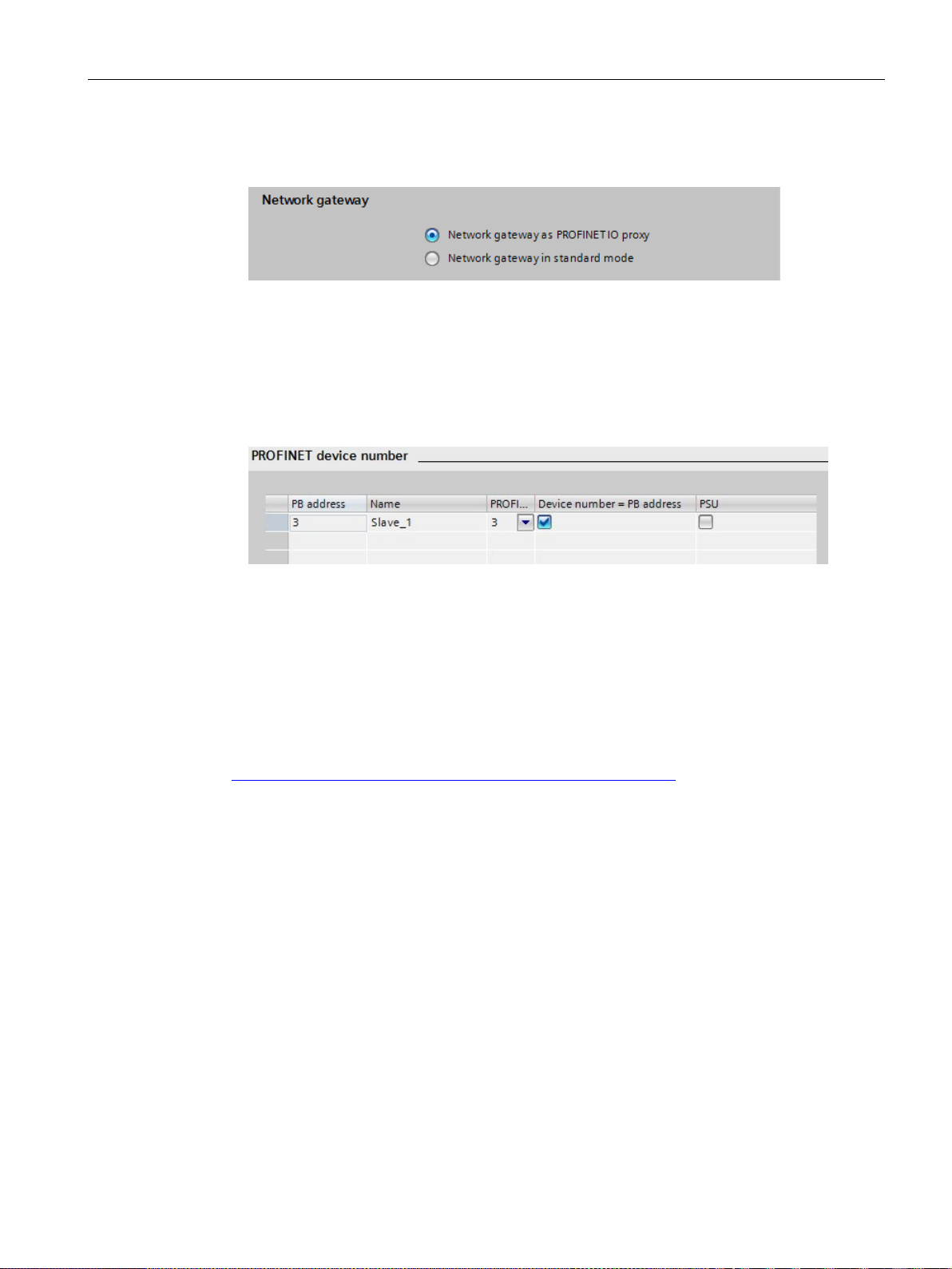
Functions
Result
Reference
5.1 Connecting other bus systems
7. In the Inspector window, go to the "Gateway" area and select the "Network gateway as
PROFINET IO proxy" option.
Figure 5-4 Setting a gateway
8. In the PROFINET device number area, you can assign a PROFINET device number for
the DP slave.
If you have selected the "Device number = PB address" check box (default), STEP 7
automatically assigns the device number according to the PROFIBUS address of the
slave. In addition, you no longer need to update the device number if the PROFIBUS
address changes.
Figure 5-5 Assigning PN device numbers for IE/PB link
You have connected the DP slave to the PROFINET IO system.
Additional information on the IE/PB link is available in the manual Gateway IE/PB Link PN IO
(http://support.automation.siemens.com/WW/view/en/19299692
).
PROFINET with STEP 7 V14
Function Manual, 09/2016, A5E03444486-AG
97
Page 98
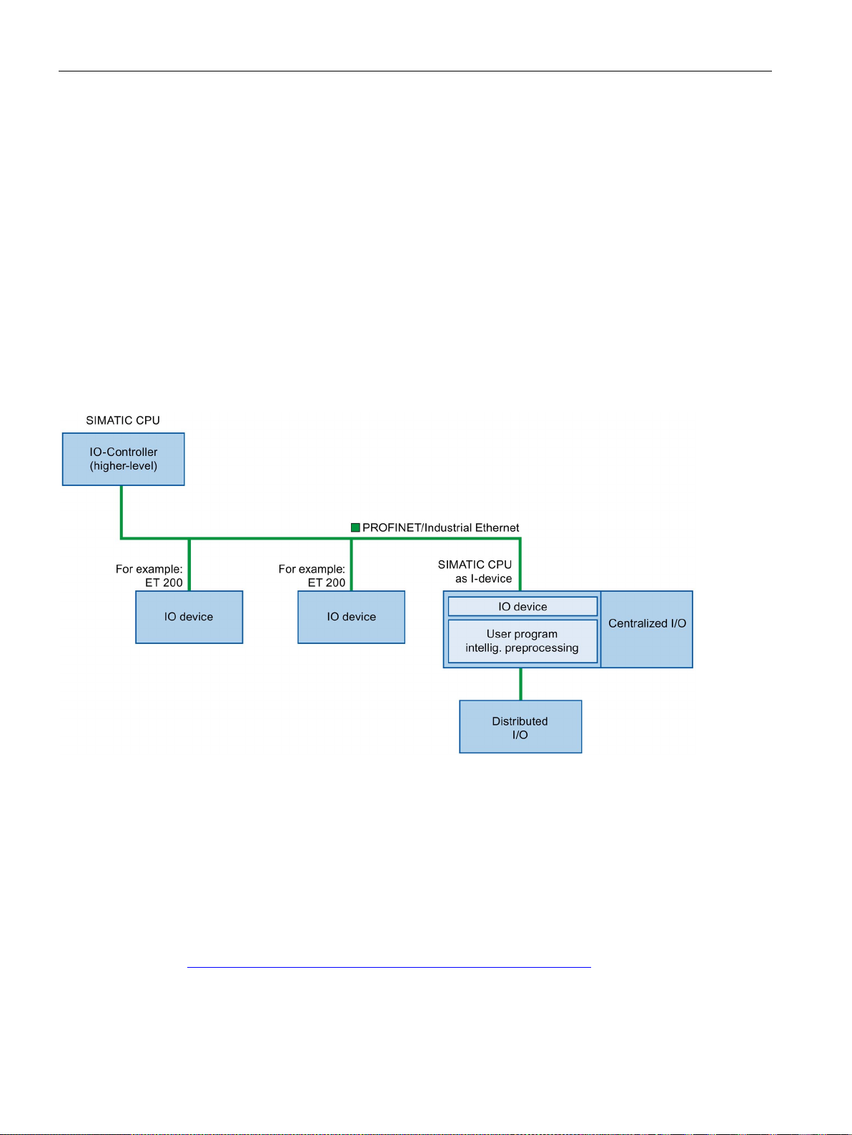
Functions
5.2
Intelligent IO devices (I-devices)
5.2.1
I-device functionality
I-device functionality
"I-device" naming conventions
Application example: Configuration and application of the PROFINET I-device function
5.2 Intelligent IO devices (I-devices)
The "I-device" (intelligent IO device) functionality of a CPU facilitates data exchange with an
IO controller and operation of the CPU as intelligent preprocessing unit of sub processes, for
example. The I-device is linked as an IO device to a "higher-level" IO controller.
The preprocessing is handled by the user program in the I-device. The process values
acquired in the centralized or distributed (PROFINET IO or PROFIBUS DP) I/O are
preprocessed by the user program and made available to the IO controller.
Figure 5-6 I-device
In the remainder of this description, a CPU or a CP with I-device functionality is simply called
an "I-device".
A detailed application example is available here
(https://support.industry.siemens.com/cs/ww/en/view/109478798
PROFINET with STEP 7 V14
98 Function Manual, 09/2016, A5E03444486-AG
).
Page 99

Functions
5.2.2
Properties and Advantages of the I-Device
Fields of application
Properties
Advantages
5.2 Intelligent IO devices (I-devices)
Fields of application of the I-device:
● Distributed processing
A complex automation task can be divided into smaller units/subprocesses. This results
in manageable processes which lead to simplified subtasks.
● Separating subprocesses
Complicated, widely distributed and extensive processes can be subdivided into several
subprocesses with manageable interfaces by using I-devices. These subprocesses can
be stored in individual STEP 7 projects if necessary, which can later be merged to form
one master project.
● Know-how protection
Components can only be delivered with a GSD file for the I-device interface description
instead of with a STEP 7 project. The know-how of the user program may no longer be
published.
Properties of the I-device:
● Unlinking STEP 7 projects
Creators and users of an I-device can have completely separated STEP 7 automation
projects. The GSD file forms the interface between the STEP 7 projects. This allows a link
to standard IO controllers via a standardized interface.
● Real-time communication
The I-device is provided with a deterministic PROFINET IO system via a PROFINET IO
interface and therefore supports RT (real-time communication) and IRT (isochronous real
time).
The I-device has the following advantages:
● Simple linking of IO controllers
● Real-time communication between IO controllers
● Relieving the IO controller by distributing the computing capacity to I-devices.
● Lower communication load by processing process data locally.
● Manageable, due to processing of subtasks in separate STEP 7 projects
PROFINET with STEP 7 V14
Function Manual, 09/2016, A5E03444486-AG
99
Page 100
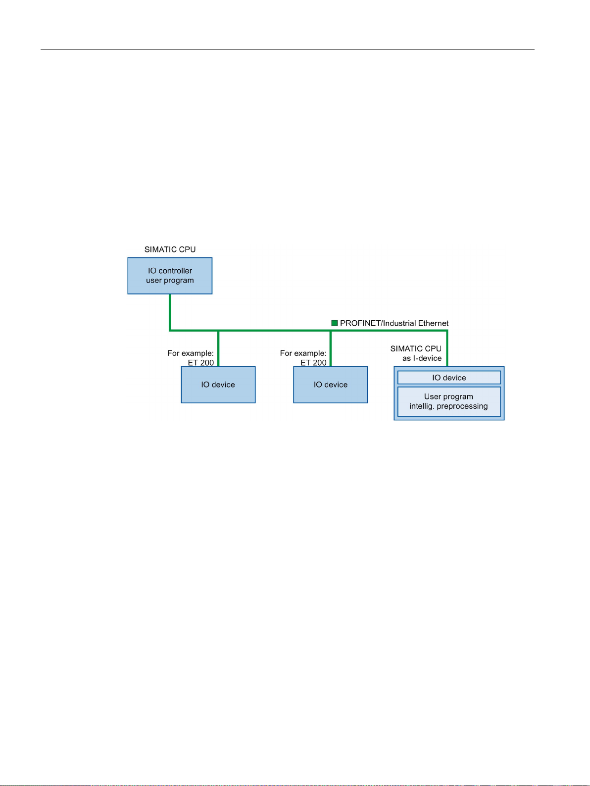
Functions
5.2.3
Characteristics of an I-Device
Principle
I-device without lower-level PROFINET IO system
5.2 Intelligent IO devices (I-devices)
An I-device is included in an IO system like a standard IO device.
The I-device does not have its own distributed I/O. The configuration and parameter
assignment of the I-devices in the role of an IO device is the same as for a distributed
I/O system (for example ET 200).
Figure 5-7 I-device without lower-level PROFINET IO system
PROFINET with STEP 7 V14
100 Function Manual, 09/2016, A5E03444486-AG
 Loading...