

Page 1
Preface, Contents
SIMATIC
PG 720 P
Programming Device
Manual
Product Overview
Unpacking and Setting Up
the PG 720
Getting to Know the PG 720
Installing and Operating the
PG 720
PG 720 Expansions
Configuring the PG 720
Error Diagnostics
Hardware Information
Appendices
1
2
3
4
5
6
7
8
C79000-G7076-C721
Edition 02
ESD Guidelines
Glossary, Index
A
Page 2
Safety Guidelines
!
!
!
This manual contains notices which you should observe to ensure your own personal safety, as well as to
protect the product and connected equipment. These notices are highlighted in the manual by a warning
triangle and are marked as follows according to the level of danger:
Danger
indicates that death, severe personal injury, or substantial property damage will result if proper precautions are
not taken.
Warning
indicates that death, severe personal injury, or substantial property damage can result if proper precautions
are not taken.
Caution
indicates that minor personal injury or property damage can result if proper precautions are not taken.
Note
draws your attention to particularly important information on the product, handling the product, or to a particular
part of the documentation.
Qualified Personnel
Correct Usage
Only qualified personnel should be allowed to install and work on this equipment. Qualified persons in the
sense of the safety guidelines of this Manual are defined as persons who are authorized to commission, to
ground and to tag equipment, systems and circuits in accordance with established safety practices and
standards.
Note the following:
Warning
!
Trademarks
The reproduction, transmission, or use of this document or its contents is
not permitted without express written authority. Offenders will be liable for
damages. All rights, including rights created by patent grant or registration
of a utility model or design, are reserved.
Siemens AG
Bereich Automatisierungs- und Antriebstechnik
Geschäftsgebiet Industrie-Automatisierungssysteme
Postfach 4848,D-90327 Nürnberg
This device and its components may only be used for the applications described in the catalog or the technical
description, and only in connection with devices or components from other manufacturers which have been
approved or recommended by Siemens.
This product can only function correctly and safely if it is transported, stored, set up, and installed correctly, and
operated and maintained as recommended.
SIMATIC, SIMATIC HMI and SIMATIC NET are registered trademarks of SIEMENS AG.
Third parties using for their own purposes any other names in this document which refer to trademarks might
infringe upon the rights of the trademark owners.
Disclaimer of LiabilityCopyright Siemens AG 1998 All rights reserved
We have checked the contents of this manual for agreement with the
hardware and software described. Since deviations cannot be precluded
entirely, we cannot guarantee full agreement. However, the data in this
manual are reviewed regularly and any necessary corrections included in
subsequent editions. Suggestions for improvement are welcomed.
Siemens AG 1998
Technical data subject to change.
Siemens Aktiengesellschaft
G79000-G7076-C721
ii
Page 3

Preface
Purpose of the
Manual
Audience
Where is this
Manual Valid?
This manual contains all the information you need for working with the
PG 720 programming device. You can use this information to do the
following:
Unpack the programming device and power it up.
Familiarize yourself with the functions and settings of the various
components (display, keyboard, programming facilities, etc.).
Connect the programming device to other units of equipment
(programmable logic controllers, other programming devices).
Expand your system, provided you comply with the necessary conditions.
Analyze and eliminate simple problems.
The following persons require the manual:
Users commissioning the programming device themselves or working
with it (editing, debugging).
System administrators operating the programming device in a network.
Service and maintenance personnel using the PG 720 for system
expansion purposes or error/fault analysis.
This manual describes the version of the PG 720 as available in June 1998.
The Product Information Bulletin supplied with the PG 720 contains the
latest technical specifications for your programming device.
Licenses
Where to Find
Information
PG 720 P Programming Device
C79000-G7076-C721-02
The approvals, certificates, and licenses for your device are supplied along
with the Product Information Bulletin.
Along with your PG 720, you also receive the following documents which
you require for commissioning the device:
The Product Information Bulletin with the valid technical specifications
of the PG 720.
A Product Information leaflet about the software supplied with the
PG 720.
For more detailed information about handling the software, please refer to
the appropriate manuals (for example, the STEP 5 manual).
iii
Page 4

Preface
Structure of the
Manual
Chapters 1 to 4 of the manual contain the most important instructions for
commissioning and using the PG 720. Chapters 5 to 8 are reference sections
required in special situations.
Setting up and getting to know your device
Before you start to use your programming device, you should read about
setting up the device in Chapter 2 and about the components and functions of
the PG 720 in Chapter 3.
Installation
Chapter 4 describes the basic steps necessary for commissioning the PG 720.
This chapter also contains instructions for working with submodules and
memory cards for programmable logic controllers and additional interfaces.
Expansion
Chapter 5 describes how to expand your PG 720 (for example, installation of
memory expansions). Please observe the safety instructions in this section.
Configuration
Modifications made to the system hardware may make it necessary for you to
adapt the original hardware configuration. This is described in Chapter 6.
Error/fault diagnostics
Chapter 7 explains how to deal with simple faults and problems that you can
diagnose and, in some cases, eliminate yourself.
Reference data
Chapter 8 contains information about hardware addresses, interrupt
assignments, and connecting cables.
Additional
Assistance
ESD guidelines
The guidelines on the handling of electrostatically sensitive devices are
particularly important for service and maintenance technicians who are
installing expansion units or carrying out error analysis with the PG 720.
Glossary
The glossary defines and explains important terms.
Alphabetical index
The alphabetical index will help you to find passages in the text relating to
important terms and keywords quickly and reliably.
If you have any questions concerning subjects not covered in the manual,
simply get in touch with the Siemens representative in your area or call the
SIMATIC Hotline. The addresses are listed in your Product Information
Bulletin.
If you have any questions about the manual itself or would like to make or
suggestions, please complete the reply card at the end of the manual. We
would also appreciate it if you would include your own opinion and appraisal
of the manual on the reply card.
PG 720 P Programming Device
iv
C79000-G7076-C721-02
Page 5

Contents
1 Product Overview 1-1. . . . . . . . . . . . . . . . . . . . . . . . . . . . . . . . . . . . . . . . . . . . . . . . . . . . . . .
2 Unpacking and Setting Up the PG 720 2-1. . . . . . . . . . . . . . . . . . . . . . . . . . . . . . . . . . . .
2.1 Setting Up the PG 720 2-2. . . . . . . . . . . . . . . . . . . . . . . . . . . . . . . . . . . . . . . . . . . .
2.2 Moving the Programming Device 2-6. . . . . . . . . . . . . . . . . . . . . . . . . . . . . . . . . . .
3 Getting to Know the PG 720 3-1. . . . . . . . . . . . . . . . . . . . . . . . . . . . . . . . . . . . . . . . . . . . . .
3.1 Hardware Components of the PG 720 3-2. . . . . . . . . . . . . . . . . . . . . . . . . . . . . .
3.2 Display 3-6. . . . . . . . . . . . . . . . . . . . . . . . . . . . . . . . . . . . . . . . . . . . . . . . . . . . . . . . .
3.3 Keyboard 3-7. . . . . . . . . . . . . . . . . . . . . . . . . . . . . . . . . . . . . . . . . . . . . . . . . . . . . . .
3.4 Trackball 3-13. . . . . . . . . . . . . . . . . . . . . . . . . . . . . . . . . . . . . . . . . . . . . . . . . . . . . . . .
3.5 Drives 3-15. . . . . . . . . . . . . . . . . . . . . . . . . . . . . . . . . . . . . . . . . . . . . . . . . . . . . . . . . .
3.6 CD-ROM Drive 3-17. . . . . . . . . . . . . . . . . . . . . . . . . . . . . . . . . . . . . . . . . . . . . . . . . .
3.7 External Power Unit and Battery 3-18. . . . . . . . . . . . . . . . . . . . . . . . . . . . . . . . . . .
4 Installing and Operating the PG 720 4-1. . . . . . . . . . . . . . . . . . . . . . . . . . . . . . . . . . . . . .
4.1 Connecting the PG 720 to the Power Supply 4-2. . . . . . . . . . . . . . . . . . . . . . . .
4.2 Battery Operation 4-3. . . . . . . . . . . . . . . . . . . . . . . . . . . . . . . . . . . . . . . . . . . . . . . .
4.3 Connecting I/O Devices 4-5. . . . . . . . . . . . . . . . . . . . . . . . . . . . . . . . . . . . . . . . . . .
4.4 Working with SIMATIC S5 Memory Submodules 4-9. . . . . . . . . . . . . . . . . . . . .
4.5 Working with SIMATIC Memory Cards 4-11. . . . . . . . . . . . . . . . . . . . . . . . . . . . . .
4.6 Working with PCMCIA Cards 4-12. . . . . . . . . . . . . . . . . . . . . . . . . . . . . . . . . . . . . .
4.7 Connecting the PG 720 to other SIMATIC S5 Units 4-13. . . . . . . . . . . . . . . . . . .
4.8 Connecting the PG 720 to a SIMATIC S7 Network (MPI/DP) 4-17. . . . . . . . . . .
4.9 Networking the PG 720 with Other Stations on PROFIBUS 4-19. . . . . . . . . . . .
4.10 Networking the PG 720 and Other Computers on Industrial Ethernet 4-20. . . .
5 PG 720 Expansions 5-1. . . . . . . . . . . . . . . . . . . . . . . . . . . . . . . . . . . . . . . . . . . . . . . . . . . . . .
5.1 Opening the Unit 5-2. . . . . . . . . . . . . . . . . . . . . . . . . . . . . . . . . . . . . . . . . . . . . . . . .
5.2 Components Visible After Opening the Unit 5-4. . . . . . . . . . . . . . . . . . . . . . . . . .
5.3 Switch Setting / Jumper 5-6. . . . . . . . . . . . . . . . . . . . . . . . . . . . . . . . . . . . . . . . . . .
5.4 Installing Memory Expansion Modules 5-7. . . . . . . . . . . . . . . . . . . . . . . . . . . . . .
5.5 Replacing the Backup Battery 5-9. . . . . . . . . . . . . . . . . . . . . . . . . . . . . . . . . . . . .
5.6 Closing the Unit 5-10. . . . . . . . . . . . . . . . . . . . . . . . . . . . . . . . . . . . . . . . . . . . . . . . . .
PG 720 P Programming Device
C79000-G7076-C721-02
v
Page 6

Contents
6 Configuring the PG 720 6-1. . . . . . . . . . . . . . . . . . . . . . . . . . . . . . . . . . . . . . . . . . . . . . . . . .
6.1 Changing the Device Configuration with SETUP 6-2. . . . . . . . . . . . . . . . . . . . .
6.1.1 The Main Menu 6-5. . . . . . . . . . . . . . . . . . . . . . . . . . . . . . . . . . . . . . . . . . . . . . . . . .
6.1.2 The Advanced Menu 6-14. . . . . . . . . . . . . . . . . . . . . . . . . . . . . . . . . . . . . . . . . . . . .
6.1.3 The Security Menu 6-16. . . . . . . . . . . . . . . . . . . . . . . . . . . . . . . . . . . . . . . . . . . . . . .
6.1.4 The Power Savings Menu 6-17. . . . . . . . . . . . . . . . . . . . . . . . . . . . . . . . . . . . . . . . .
6.1.5 The Exit Menu 6-19. . . . . . . . . . . . . . . . . . . . . . . . . . . . . . . . . . . . . . . . . . . . . . . . . . .
6.2 Configuring the PCMCIA Interface 6-22. . . . . . . . . . . . . . . . . . . . . . . . . . . . . . . . . .
7 Error Diagnostics 7-1. . . . . . . . . . . . . . . . . . . . . . . . . . . . . . . . . . . . . . . . . . . . . . . . . . . . . . . .
8 Hardware Information 8-1. . . . . . . . . . . . . . . . . . . . . . . . . . . . . . . . . . . . . . . . . . . . . . . . . . . .
8.1 Hardware Address Table 8-2. . . . . . . . . . . . . . . . . . . . . . . . . . . . . . . . . . . . . . . . . .
8.2 Interrupt Assignments 8-6. . . . . . . . . . . . . . . . . . . . . . . . . . . . . . . . . . . . . . . . . . . .
8.3 PG 720 Video Modes 8-7. . . . . . . . . . . . . . . . . . . . . . . . . . . . . . . . . . . . . . . . . . . . .
8.4 Connector Pinouts 8-8. . . . . . . . . . . . . . . . . . . . . . . . . . . . . . . . . . . . . . . . . . . . . . .
8.5 Connecting Cables 8-15. . . . . . . . . . . . . . . . . . . . . . . . . . . . . . . . . . . . . . . . . . . . . . .
A Guidelines for Handling Electrostatically-Sensitive Devices (ESD) A-1. . . . . . . . . .
A.1 What is ESD? A-2. . . . . . . . . . . . . . . . . . . . . . . . . . . . . . . . . . . . . . . . . . . . . . . . . . .
A.2 Electrostatic Charging of Persons A-3. . . . . . . . . . . . . . . . . . . . . . . . . . . . . . . . . .
A.3 General Protective Measures Against Electrostatic Discharge Damage A-4.
Glossary Glossary-1. . . . . . . . . . . . . . . . . . . . . . . . . . . . . . . . . . . . . . . . . . . . . . . . . . . . . . . . . .
Index Index-1. . . . . . . . . . . . . . . . . . . . . . . . . . . . . . . . . . . . . . . . . . . . . . . . . . . . . . . . . . . . . . . . .
PG 720 P Programming Device
vi
C79000-G7076-C721-02
Page 7
Product Overview
1
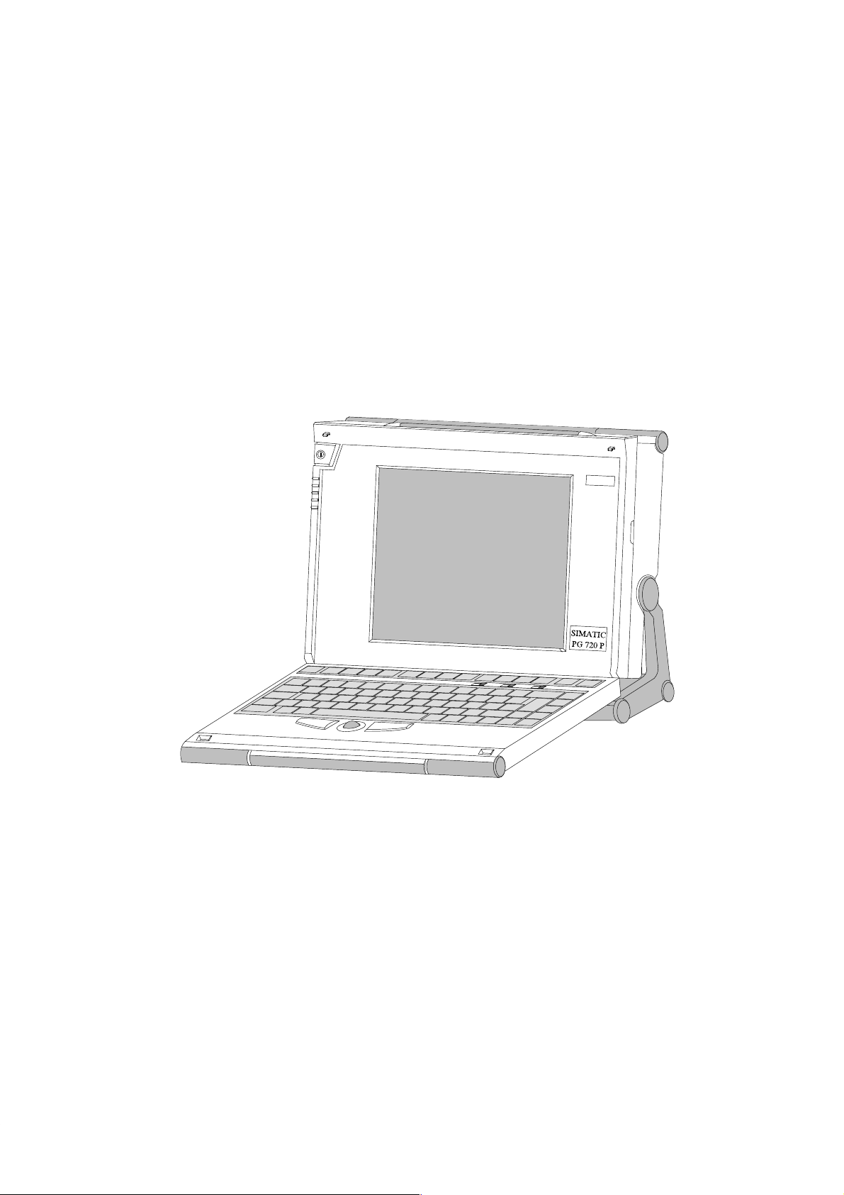
Application
The PG 720 programming device is a self-contained unit designed specifically
for an automation environment. Its performance, ergonomic design, and
equipment make it a unit particularly suitable for maintenance and service as
well as for programming, configuring, debugging, and installing SIMATIC
programmable logic control systems.
SIEMENS
The PG’s Hardware
and Software
PG 720 P Programming Device
C79000-G7076-C721-02
You can use the PG 720 programming device to program SIMATIC S5 and
SIMATIC S7 programmable logic controllers. It is equipped with the following:
Interface ports for connection to programmable logic controllers.
Programming facilities for S5 memory submodules and S5/S7 memory
cards.
The PG 720 is supplied with system and automation software. The software
components are listed in the Product Information leaflet.
1-1
Page 8

Product Overview
Advantages of the
PG 720
Compared with a PC with standard hardware and software, the PG 720
programming device of the SIMATIC family has numerous advantages:
You can develop, debug, and document user programs for SIMATIC S5
and SIMATIC S7 programmable logic controllers with the PG 720
without the need for additional hardware or software.
The rugged design and practical functions of the PG 720 make it
particularly suitable for use on-site under tough industrial conditions. It is
extremely light and easy to transport. The PG 720 meets the specific
requirements of industrial environments such as noise immunity,
compliance with the relevant standards, ruggedness, simple
transportation, and commissioning.
The PG 720 is equipped with a battery allowing it to be operated without
a mains connection.
The PG 720 can be set up and operated in a large number of different
ways and positions, and can therefore be used practically anywhere it is
needed.
The PG 720 has all the integral ports necessary for connecting it to
SIMATIC automation devices:
– Programming interface for SIMATIC S5 memory submodules.
– Programming interface for SIMATIC S5 and SIMATIC S7 memory
cards in credit card format.
– Communication interfaces for connection to S5 and S7 programmable
logic controllers.
The PG 720 is supplied with all the necessary system and automation
software already installed on the hard disk in compressed form.
Since Windows 95 is also already installed, you can, of course, also use
the PG 720 as a stand-alone workstation, and run all the standard software
available on the market that requires MS-DOS or Windows.
In terms of performance and expansion capability, your programming
device meets all the normal requirements of a PC. This means that the
PG 720 can also be used as a fully-fledged personal computer.
1-2
PG 720 P Programming Device
C79000-G7076-C721-02
Page 9

Unpacking and Setting Up the PG 720
2
What Does This
Chapter Contain?
Chapter
Overview
This chapter contains important information about unpacking, setting up, and
transporting the PG 720, such as:
Opening and closing the keyboard
Changing the angle of inclination of the device
Using the extra pull-out support
How to move the unit.
Section Contents Page
2.1 Setting Up the PG 720 2-2
2.2 Moving the Programming Device 2-6
PG 720 P Programming Device
C79000-G7076-C721-02
2-1
Page 10
Unpacking and Setting Up the PG 720
2.1 Setting Up the PG 720
Unpacking Your
PG 720
!
Setting Up on a
Desk Top
Unpack your PG 720 as follows:
1. Remove the packing.
2. Do not throw the original packing away. Keep it in case you have to ship
or transport the unit again at some time in the future.
3. Check the packing list to make sure that no components are missing.
Caution
Risk of damage!
Moisture inside the unit can cause serious damage.
When transporting the unit in cold weather, when it may be submitted to
extreme variations in temperature, make sure that the unit is allowed to
reach room temperature slowly before you switch it on.
If condensation has formed, this must be allowed to evaporate before you
switch on. If, for example, the unit is subjected to a temperature change from
–20° C to +20° (–4° F to +68° F) you should wait approximately 12 hours
before switching on the unit.
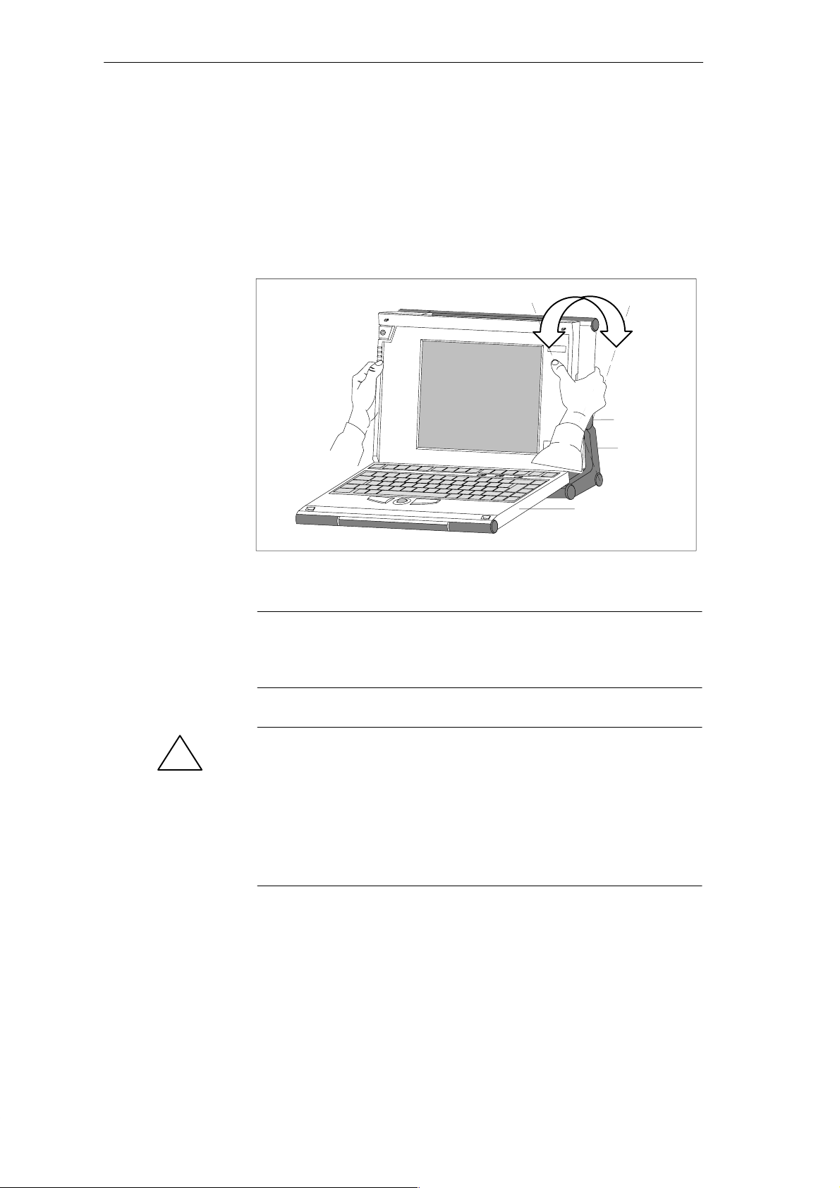
The PG 720 is used primarily on a desk or table top. T o ensure a comfortable
working position, the PG 720 can be adapted as follows to suit the work
place:
1. Place the PG 720 on the desk or table top.
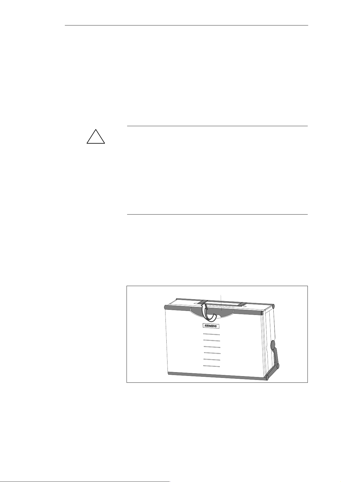
2. Open the keyboard lock by pulling up the gray handle.
3. Lower the keyboard into position.
Handle
Figure 2-1 The Programming Device before Opening
2-2
PG 720 P Programming Device
C79000-G7076-C721-02
Page 11
Unpacking and Setting Up the PG 720
Changing the
Angle of
Inclination
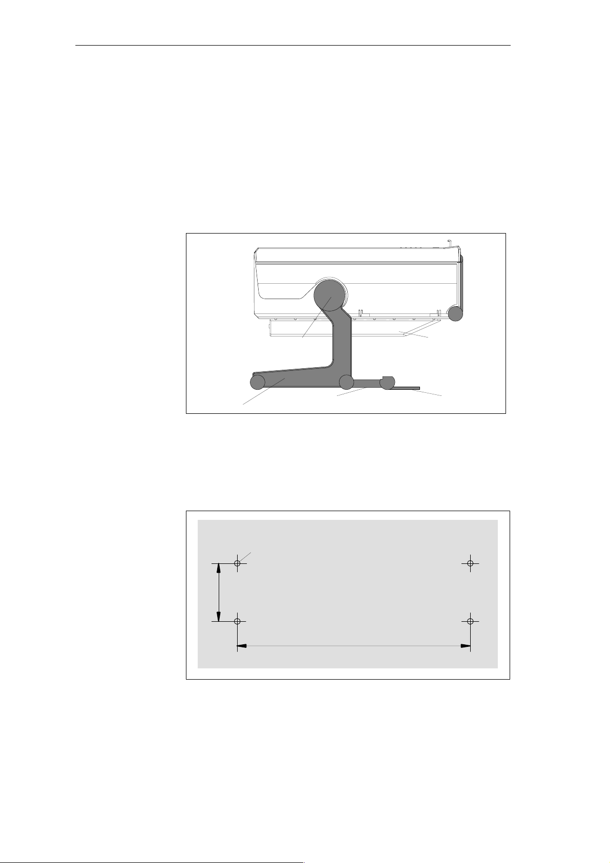
With the keyboard open, you can incline the PG 720 to any angle between 0°
and 90°. T o adjust the angle, proceed as follows:
1. Lower the keyboard into position.
2. Pull the support (Figure 2-4) out of the rear of the stand and, if necessary,
pull out the extra support hoop.
3. Incline the unit to an angle that will allow you to work comfortably.
SIEMENS
Pivot
PG 720
Keyboard opened
Stand
Figure 2-2 Changing the Angle of Inclination
Note
When you change the angle of inclination, make sure that the keyboard
cable is not trapped between the device and the stand.
Caution
!
Risk of injury!
There is a danger of the unit tipping over if it is set up at an angle of
inclination of more than 15°
without using the pull-out support. This could
lead to personal injury and also damage to the unit.
If the angle of inclination is greater than 15°, you must use the pull-out
support and, if necessary, the extra support hoop in the stand.
PG 720 P Programming Device
C79000-G7076-C721-02
2-3
Page 12

Unpacking and Setting Up the PG 720
Detaching the
Keyboard
In certain situations, it is helpful to remove the keyboard.
Press in the catches in the
middle of the hinges
Figure 2-3 Detaching the Keyboard
Detaching
Refitting
Caution
!
Risk of tipping!
If the keyboard is detached, there is a risk of the unit tipping over. Before
removing the keyboard, make sure that you pull out the support from the
device stand (Figure 2-4) and pull out the additional hoop.
You detach the keyboard as follows:
1. Grip the keyboard hinges in the stand behind the keyboard.
2. Pull the locks in the middle of the hinge assembly towards the keyboard.
3. Pull the keyboard up and out.
4. Place the keyboard on a suitable surface, using the hinge assembly as a
stand.
You attach the keyboard again as follows:
1. Place the keyboard cable in the cable conduit in the stand.
2. Snap the keyboard hinges into the receptacles in the stand.
Note
When attaching the keyboard, make sure that the cable is lying correctly in the
cable conduit and is fixed in position.
2-4
PG 720 P Programming Device
C79000-G7076-C721-02
Page 13
Unpacking and Setting Up the PG 720
Keyboard Angle
Horizontal
Position
Adjustment
When the keyboard is attached to the unit, its angle of inclination is 6°, the
height of the middle row of keys is 30 mm (about 1 inch). When it is
detached, the angle of inclination is 4.5°, and the height of the middle row of
keys is 27 mm. This is an ideal ergonomic design to allow a comfortable
working position.
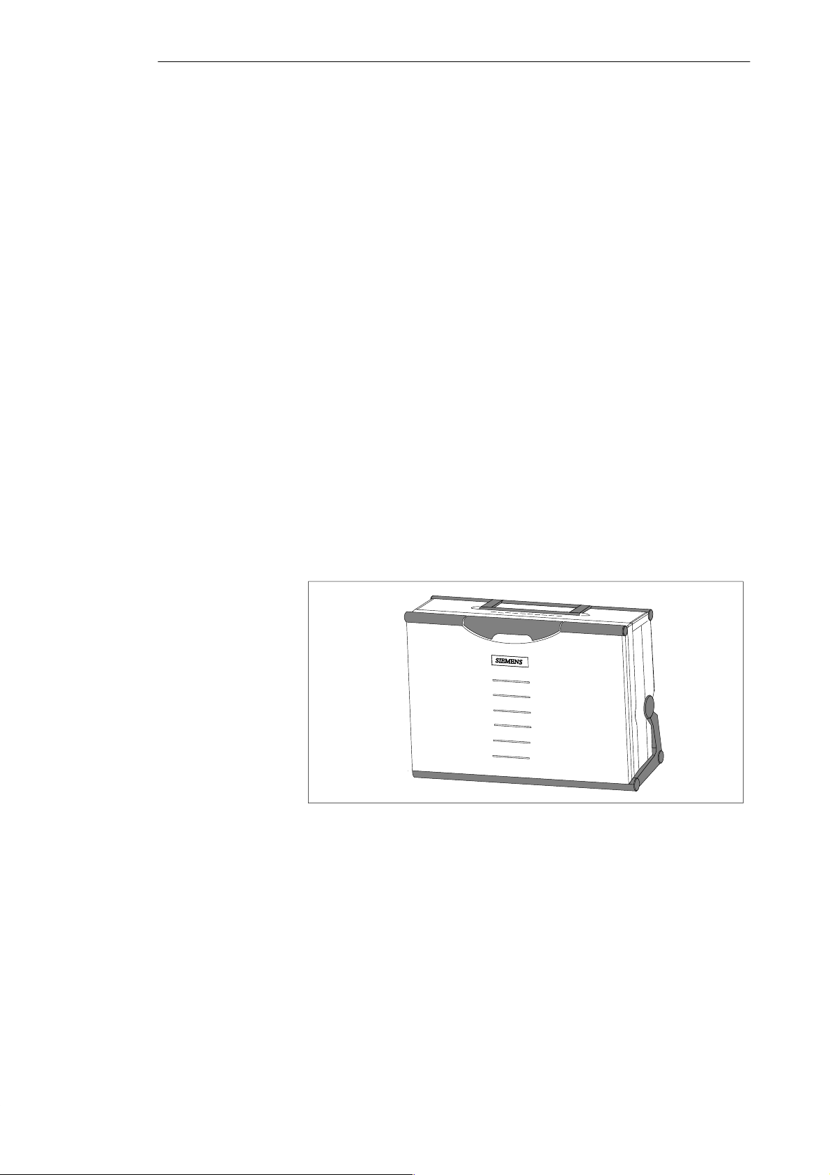
If no table or desk is available, the unit can be operated on the floor. You can
adjust the casing and display through approximately 90
o
into the horizontal
plane.
Pivot
CD-ROM drive
Wall Mounting
Stand
Figure 2-4 Horizontal Operating Position Without Keyboard
Support
Extra support hoop
The basic unit can be attached to a wall. Four drilled holes (6 mm diameter)
are provided in the unit stand for this purpose.
ø6
46
267
Figure 2-5 Drilling Template for Wall Mounting (dimensions in millimeters)
PG 720 P Programming Device
C79000-G7076-C721-02
2-5
Page 14
Unpacking and Setting Up the PG 720
2.2 Moving the Programming Device
Preparations
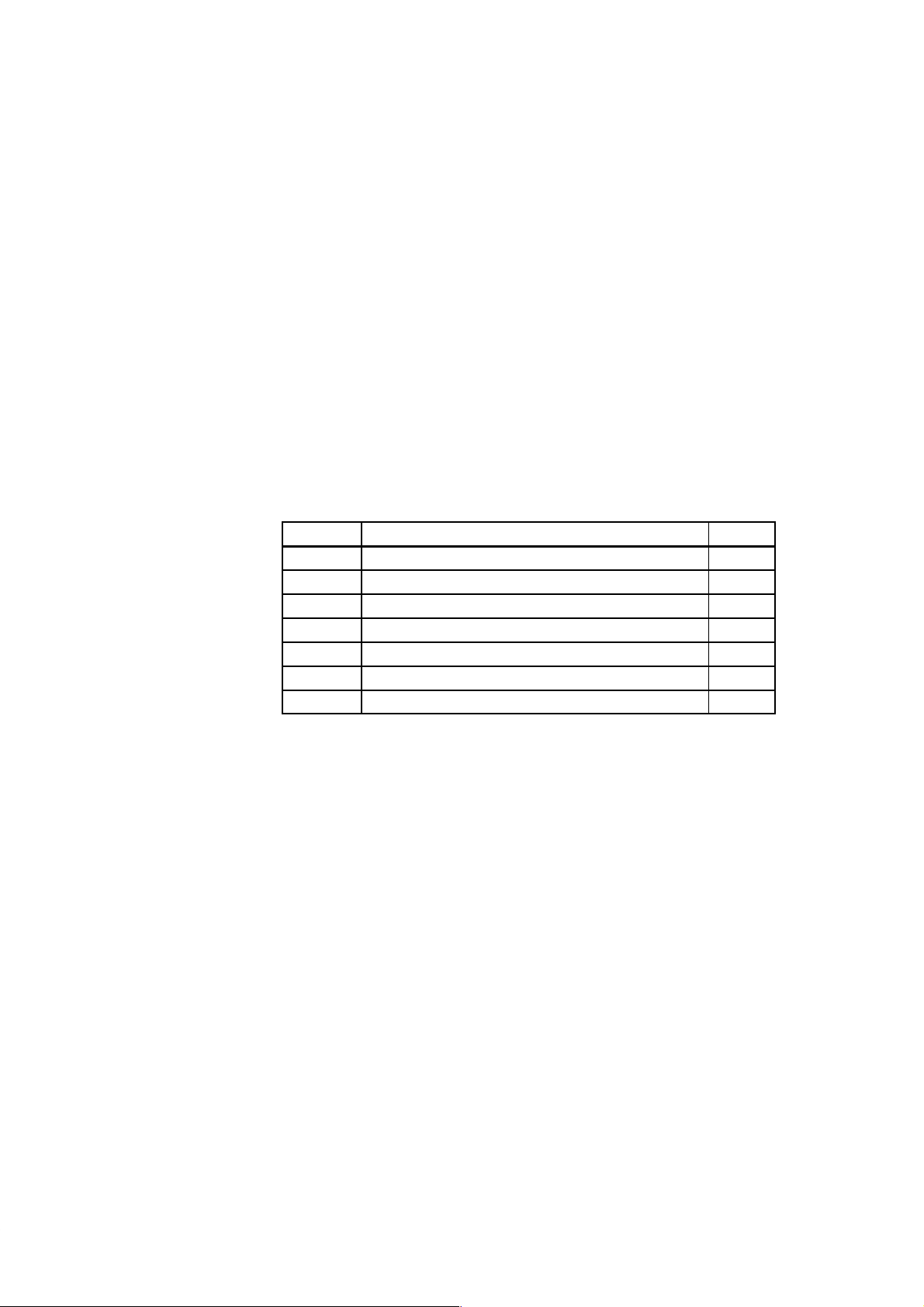
The PG 720 is easy to carry. Before carrying it, however, you should take the
following measures:
1. Shut down the operating system. T o prevent data loss, you must exit
Windows completely. Windows issues a message to inform you when it is
safe to switch off the device.
2. After shutting down the operating system, wait approximately 5 seconds
before you switch the device off. This allows the drive to come to a
complete stop and ensures optimal protection.
3. Unplug all the connecting cables.
4. Close the covers protecting the ports and connections on the right-hand
and left-hand side panels.
5. Bring the unit into an upright position.
6. Raise the keyboard and lock it by pressing it against the front panel of the
unit. The latches on the right and left snap in. Make sure that both catches
are properly locked.
7. If you only want to carry the unit for a short distance, use the handle.
8. If you want to move the PG 720 over larger distances, pack the unit and
all its accessories in the carrying bag supplied.
Carrying the
PG 720
2-6
Figure 2-6 PG 720 Ready for Transport
Despite the rugged design of the PG 720, its internal components are
sensitive to severe vibration or jolts. When moving the PG 720, you must
therefore make sure that it is protected from severe mechanical forces.
Use the original packing material if you have to ship the PG 720 from one
location to another.
PG 720 P Programming Device
C79000-G7076-C721-02
Page 15
Getting to Know the PG 720
3
What Does This
Chapter Contain?
Chapter
Overview
This chapter contains all the information you require about the most
important components of the device, such as:
LED displays
Drives
Keyboard
Programming facilities of the PG 720
External power unit and battery.
Section Contents Page
3.1 Hardware Components of the PG 720 3-2
3.2 Display 3-6
3.3 Keyboard 3-7
3.4 Trackball 3-13
3.5 Drives 3-15
3.6 CD-ROM Drive 3-17
3.7 External Power Unit and Battery 3-18
PG 720 P Programming Device
C79000-G7076-C721-02
3-1
Page 16
Getting to Know the PG 720
3.1 Hardware Components of the PG 720
Front
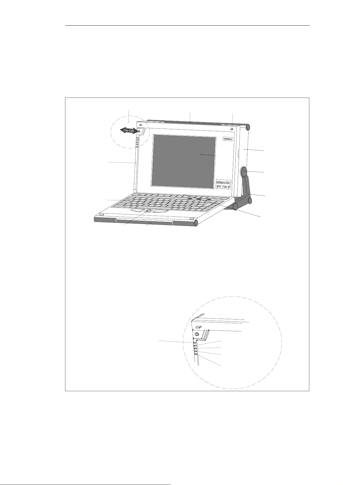
You can access all of the important operator controls and displays from the
front, base, or sides of the unit. Figure 3-1 shows the front of the PG 720.
1
7
6
1 On/Off switch
2 Carrying handle
3 LC display
4 Coverplate for module ports, memory card
ports, PCMCIA ports, and floppy disk drive
5 Stand
1 On/Off switch
1)
2 Carrying handle
The coverplates are used to protect the ports from dust,
and can be removed and replaced as required.
3 LC display
2)
Can be accessed from the base when the device is turned
upside down.
4 Ventilating slots
5 Coverplate for memory submodules,
PCMCIA, interface ports and floppy disk
1)
drive
6 Stand
7 Keyboard
8 Interface ports
9 Trackball
Power LED
10 Catches for locking keyboard
Green: Power connected, battery charged
11 Pivot
Orange: Power connected, battery charging
12 Protector strip
Red: Rechargeable battery almost
8
discharged, device about to be
switched off
13Detail
2
9
3
4
10
5
12
11
6 Keyboard
7 Coverplate for COM1/COM2 port,
MPI/DP port, mouse port, and LPT1/printer
1)
port
8 Trackball
1)
9 Catches for locking keyboard
10 Pivot
11 Protector strip
12 CD-ROM drive
Detail
2)
13
LEDs
Hard disk access
CD-ROM drive access
Floppy disk access
Submodule programming
active
MPI port active
detached and snapped back on.
Figure 3-1 The Front of the PG 720
3-2
PG 720 P Programming Device
C79000-G7076-C721-02
Page 17
p
pp
Getting to Know the PG 720
Left-Hand Side
Panel
(Communications
Side)
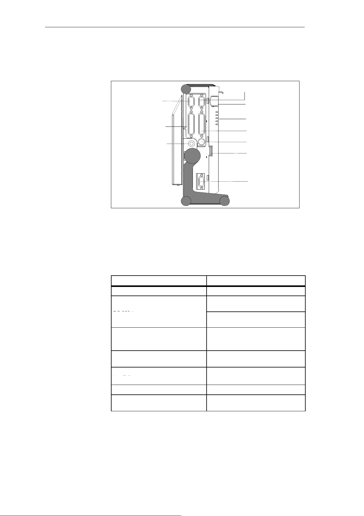
All the connectors and interface ports for connecting to external devices are
located on the left side panel of the PG 720 (communications side).
VGA port
COM 2 port
COM 1 port
Power supply
connector socket
Figure 3-2 Left-Hand Side Panel with Cover Plates Removed
Power switch
LEDs
LPT1 port
PS/2 mouse
Contrast control
MPI/DP port
Connectors and
Ports
The following table contains an overview of the various interface ports and
connectors on the left-hand side panel:
Table 3-1 Connectors on the Left-Hand Side Panel of the Unit
Ports and Connectors
VGA port Connection for external monitor
COM 2
Connection for serial mouse
Serial port
RS-232 / mouse
Serial port
COM 1
RS-232 /MODEM /PLC
Connection for serial printer
Connection for S5 programmable logic
controller
Serial port
MPI (multipoint interface) Connection for S7 programmable logic
controller
LPT 1 printer
Connection for parallel printer
Parallel port
PS/2 mouse Connection for PS/2 mouse
External power supply unit Connection for 17 V DC from external
power supply unit
Function
PG 720 P Programming Device
C79000-G7076-C721-02
3-3
Page 18
Getting to Know the PG 720
Right-Hand Side
Panel (Processing
Side)
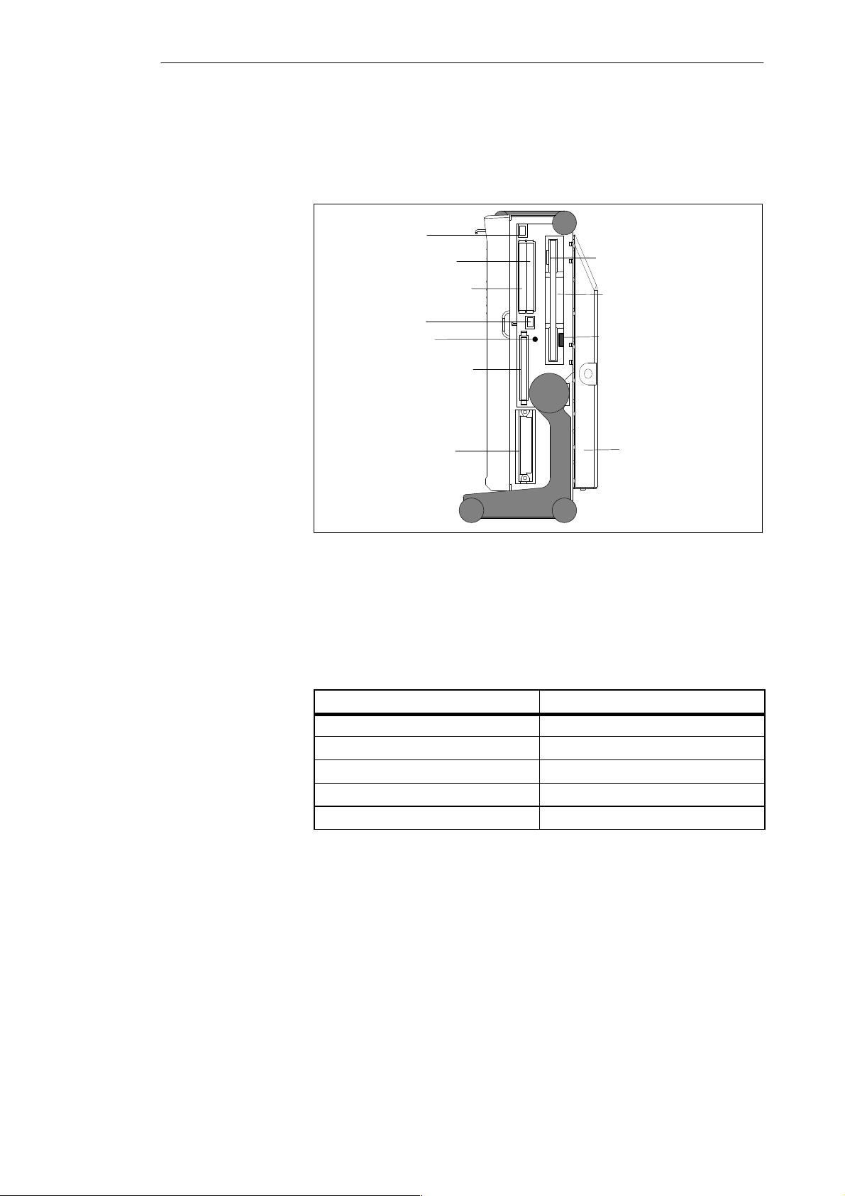
You access the slots for programming S5 submodules, S5/S7 memory cards,
the PCMCIA port, and the disk drive from the right-hand side of the PG 720
(processing side).
Ejector for PCMCIA
cards
PCMCIA type II; slot 2
PCMCIA type II/III; slot 1
Ejector for PCMCIA
cards
Orientation point
Memory card port
S5 submodule port
Ejector for diskettes
3.5 in. disk drive
Access LED
CD-ROM drive
Figure 3-3 Right-Hand Side Panel (with Port Covers Removed)
The following table contains an overview of the ports and connectors on the
right-hand side panel:
Table 3-2 Connectors on the Right-Hand Side Panel of the Unit
Interface Port Function
PCMCIA type II port ; slot 2 Connection for PCMCIA type II cards
PCMCIA type III port; slot 1 Connection for PCMCIA type II/III cards
S5 submodule port Programming SIMATIC S5 submodules
Memory card port Programming SIMATIC memory cards
Disk drive Working with 3.5” disks
3-4
PG 720 P Programming Device
C79000-G7076-C721-02
Page 19
Getting to Know the PG 720
Base Panel
Ventilation Slits
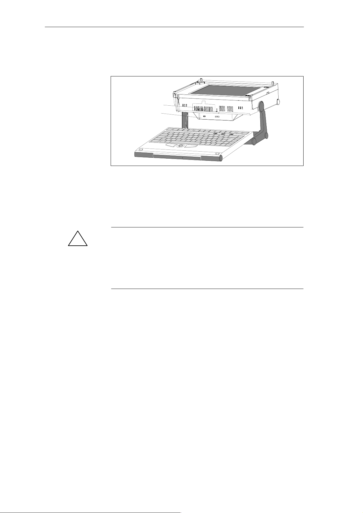
You can access the CD-ROM drive and the rechargeable battery from the base
of the PG 720 device.
Battery
CD-ROM-Drive
There are ventilation slits on the top and bottom panels of the unit. These
slits must not be covered or blocked in any way (for example, by placing the
device on carpets or rugs).
Caution
!
Risk of overheating!
If you cover the inlet or outlet ventilation slits, you may cause damage to the
PG 720.
Do not place any objects so that they obstruct the ventilating slits in any
way .
PG 720 P Programming Device
C79000-G7076-C721-02
3-5
Page 20
Getting to Know the PG 720
3.2 Display
Available Displays
Color Display of
the PG 720
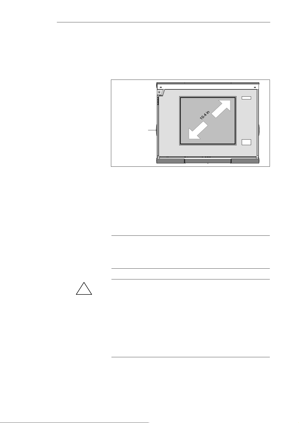
The PG 720 has a color display.
Contrast control
Figure 3-4 PG 720 Display
The display of the PG 720 is an STN color display with a diagonal of 10.4 in.
(26 cm) and a resolution of 800 x 600 pixels.
The three primary colors, red, green and blue, can each be displayed in eight
different shades. This means that, including all the secondary colors, a
maximum of 256 different colors can be displayed. The contrast can be
adjusted with a control to the left of the display.
3-6
Note
Depending on the gray tone or color shade in the display, passive STN
displays are subject to varying degrees of interference known as the Moiré
effect. This is a physical characteristic and is not a fault.
Caution
!
Risk of injury!
If a display is damaged, liquid crystals may escape. Do not touch this liquid
or allow it to come into contact with your skin in any way, and do not breath
in the vapors. If you do come into contact with the liquid, wash those parts
of the skin affected immediately with alcohol, and rinse with plenty of water.
Then consult a physician immediately.
Use only a cotton cloth and a neutral cleansing agent to clean the display. Do
not use water or aggressive solvents (such as alcohol or acetone). Never
touch the display with hard, sharp objects. Avoid exerting any pressure on
the display surface.
PG 720 P Programming Device
C79000-G7076-C721-02
Page 21
3.3 Keyboard
Getting to Know the PG 720
Keyboard Layout
Esc
~
Cap
s
Lock
Ctrl Alt
F1 F2 F3 F4 F5 F6 F7 F8
!
@ ”
1234 567{890– ß
QWE RTYU IO P Ü
@
AS D F GH J K L
>
<
n
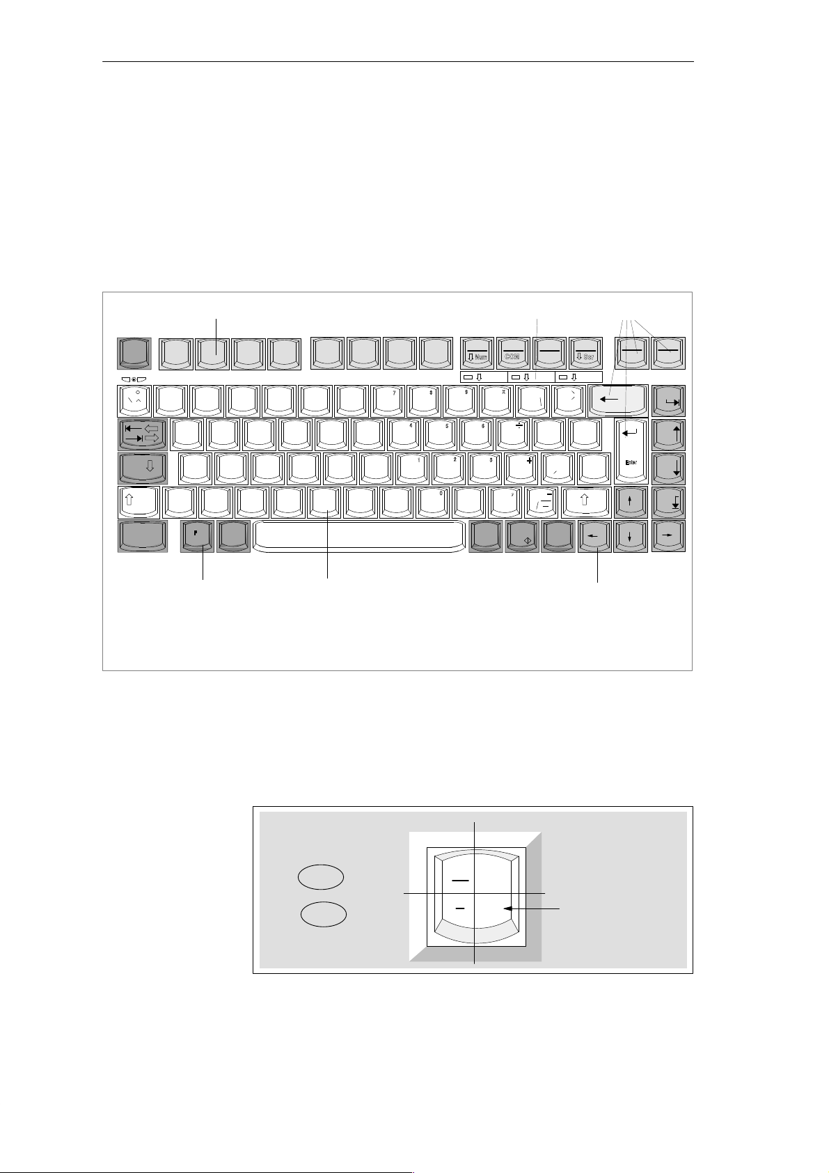
The keyboard is divided into the following areas:
S Alphanumeric or typewriter keyboard with special keys
S LED displays
S Function keys
S Cursor control keys.
3
$ % ^ & & / * ( ( ) ) = __?
# w
Y
XC BN
Z
V
[
< ;,> :.?
M
5
F9
F10
F11 F12
kkk
Num Scroll
+
{
[
Ö
=
Ä
”
Delete
}
:
;
Insert
Alt
Gr
2
Print Pause
BreakSysRq
Home
}
*
~
+
]
|
’
#
\
Page
Page
End
2
1 Alphanumeric keyboard
2 Special keys
Figure 3-5 Keyboard Layout
Repeat Function
All the keys on the keyboard are of the autorepeat type. The character is
repeated as long as the key is pressed.
Keyboard Labeling
The keyboard has international and German labeling.
Figure 3-6 The Keyboard Labeling System
1
3 Function keys
4 Cursor control keys
Shift
Unshift
International
5 LED display
National
?
\
ß
4
Example: German
Font size and thickness
reduced
Together
with the ALT
GR
key
PG 720 P Programming Device
C79000-G7076-C721-02
3-7
Page 22
Getting to Know the PG 720
Alphanumeric
Keyboard
Special Keys
The largest block of keys on the keyboard is the alphanumeric keyboard with all
the keys for the letters of the alphabet, numerals and special characters. The
characters are arranged in basically the same way as on a normal typewriter.
However, there are a number of special keys which have special functions for
the PG 720.
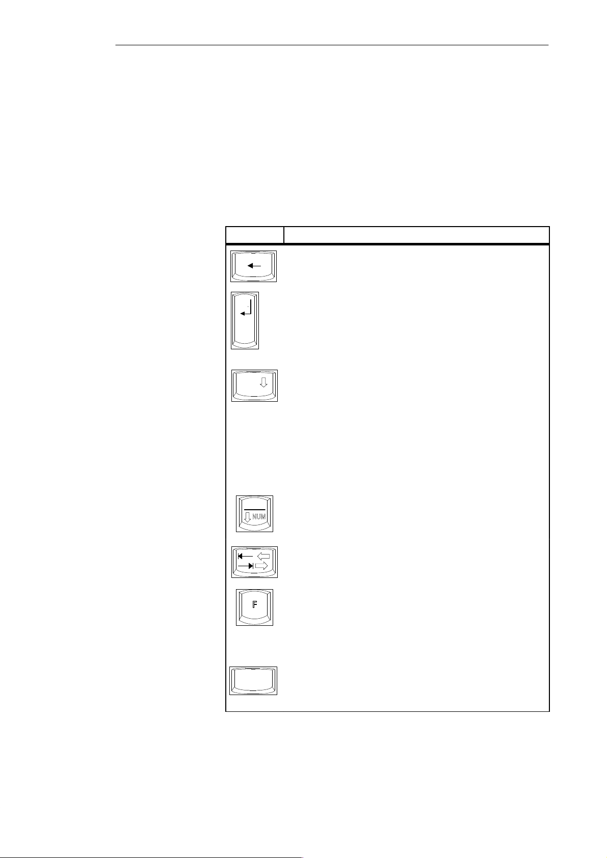
The special keys in the alphanumeric keyboard have the following functions:
Table 3-3 Functions of the Special Keys
Key Function
Backspace Key
This key moves the cursor one space to the left and deletes the
character at this position.
Enter Key
(Return, Enter, Line Feed (“New Line”)
Enter
Caps
Lock
F9
The return or enter key is used mainly to terminate a command line in
the operating system; that is, the command you have typed in is
executed when you press this key. For other uses of this key, please
refer to the user manual of the relevant user program.
CAPS LOCK Key
If you press this key, the middle LED at the top right-hand corner of
your keyboard lights up. All upper case characters and other characters
are output normally. If you want to type lower case letters in this
position, you must first press the shift key.
If you are using an international keyboard, you cancel this function by
pressing the CAPS LOCK key again. The LED then goes out.
If you have a German keyboard, you must press the shift $ key to
cancel this function.
NUM Key
With these keys F
from the alphanumeric keyboard to numeric keys. The LED display
lights up. Press this key again to return to cursor control.
Tabulator Key
This moves the cursor depending on the selected tabulator positions.
+ ^ NUM , the emulated numeric block is switched
n
3-8
Ctrl
“Fn” Special Key (combination key)
n
In conjunction with a second key (key combination), you activate
other key codes for special applications with this key (see Figure 3-9
Function Keys). This key is also used to emulate the numeric keypad
(Figure 3-8 Numeric Keypad).
CTRL Key (combination key)
This key is only used in combination with other keys. For example,
you press CTRL + ALT + Delete to reset and restart the operating
system. For other uses of this key, please refer to the user manual of the
relevant user program.
PG 720 P Programming Device
C79000-G7076-C721-02
Page 23
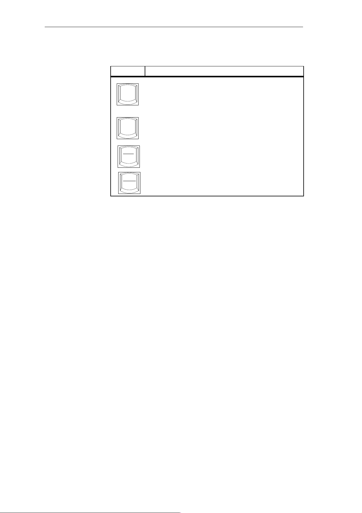
Table 3-3 Functions of the Special Keys
Key Function
ALT Key (combination key)
Alt
Alt
Print
SysRq
This key is only used in combination with other keys. For example,
you can enter the hexadecimal value of an ASCII character using this
key and the numeric keypad for example, F
to “{”.
ALT
Key (combination key)
Gr
You can use this key together with the other combination keys to
Gr
generate other key codes. For example, you can generate the “\”
character on the German keyboard by typing ALT
PRINT (combination key)
Using the Print key, you can output the current screen display to a
printer (depending on the software used).
Getting to Know the PG 720
+ ALT + 123 corresponds
n
+ ß.
Gr
LED Displays
Pause
Break
PAUSE (combination key)
The Pause key interrupts program execution in the majority of
applications.
The LED displays for the keys NUM LOCK and SCROLL LOCK are located
below the function keys F9 to F12 and display the current status of the keys.
NUM LOCK
CAPS LOCK
SCROLL LOCK
When the programming device is powered up, the LED displays for the NUM
LOCK, CAPS LOCK, and SCROLL LOCK keys light up briefly twice. The
keyboard is then ready for operation.
PG 720 P Programming Device
C79000-G7076-C721-02
3-9
Page 24

Getting to Know the PG 720
Cursor Keys
The key block shown in the picture below is used for cursor control.
Move cursor up
Move cursor left
Figure 3-7 Cursor Control Keys
Home
Page
Page
End
Move cursor down
Move cursor to
beginning of file
Page back
Page forward
Move cursor to end
of file
Move cursor right
Numeric Keypad
with Fn Key
Function Keys
By pressing Fn and one of these keys, the numbers and characters can be used
provided Num Lock is switched on.
& / * ( ( ) ) =
7{ 8 9 0
n
+
UIOP
Figure 3-8 Numeric Keypad
[
JKL
M
> :
}
.
:
Ö
;
?
There is a row with twelve function keys located above the alphanumeric
keyboard. The assignment of the individual function keys depends on the
software you are working with.
F
+ F9 can also be used to switch the numeric keypad from alphanumeric
n
keys to numeric keys.
3-10
PG 720 P Programming Device
C79000-G7076-C721-02
Page 25
Getting to Know the PG 720
Keys with Specific
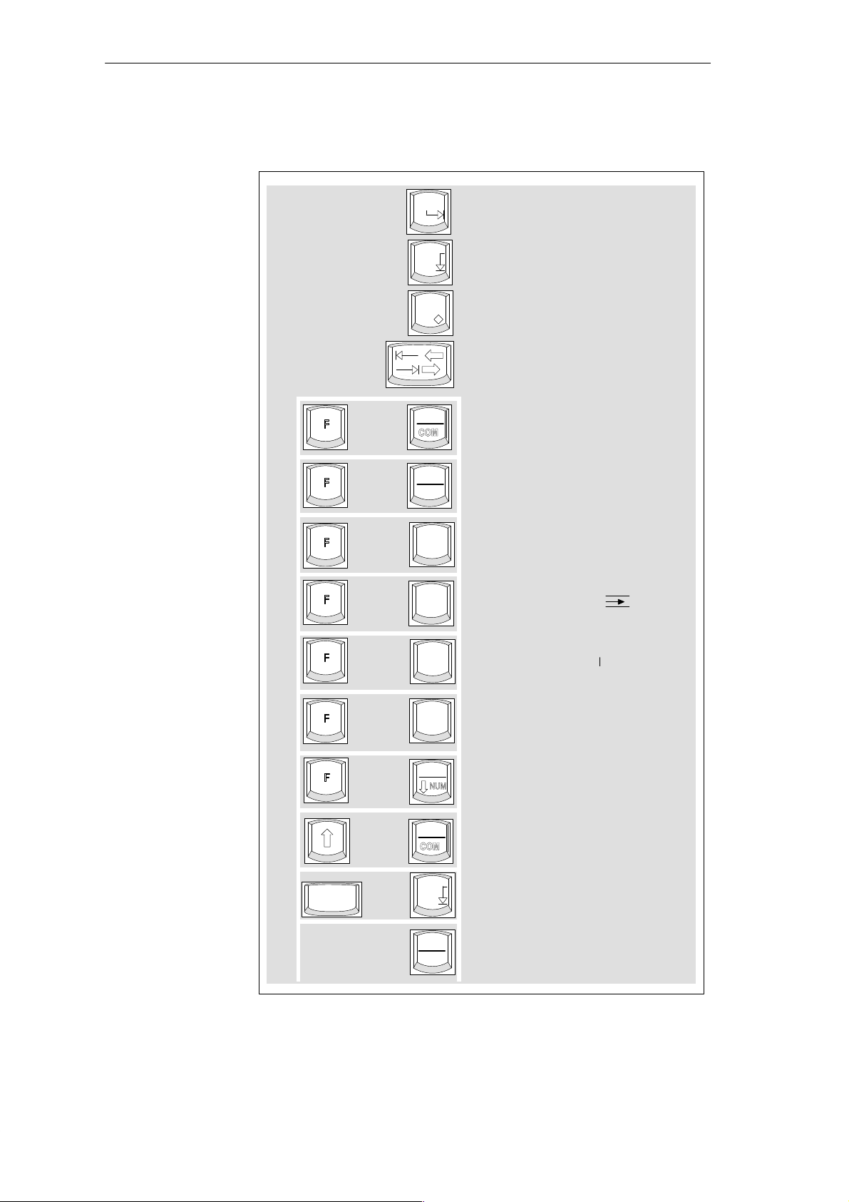
Functions for S5
The following function keys have specific functions in conjunction with the
STEP 5 programming software.
Home
Horizontal expand
End
Insert
n
n
n
+
+
+
F10
F11
F1
Vertical expand
Enter key
Cursor right/
cursor left
Title/comment input in
segments
End of segment
Help
n
n
n
n
+
+
+
+
F2
F3
F4
F9
F10
+
CTRL
Figure 3-9 Function Keys (STEP 5)
+
End
Pause
Break
Insert segment
Delete segment (X
Correction (CORR)
Switch the emulated numeric
keypad from alphanumeric to
numeric keys
Zoom (in Graph 5)
Zoom (in Graph 5)
Half screen (in Graph 5)
)
PG 720 P Programming Device
C79000-G7076-C721-02
3-11
Page 26
Getting to Know the PG 720
Key Combinations
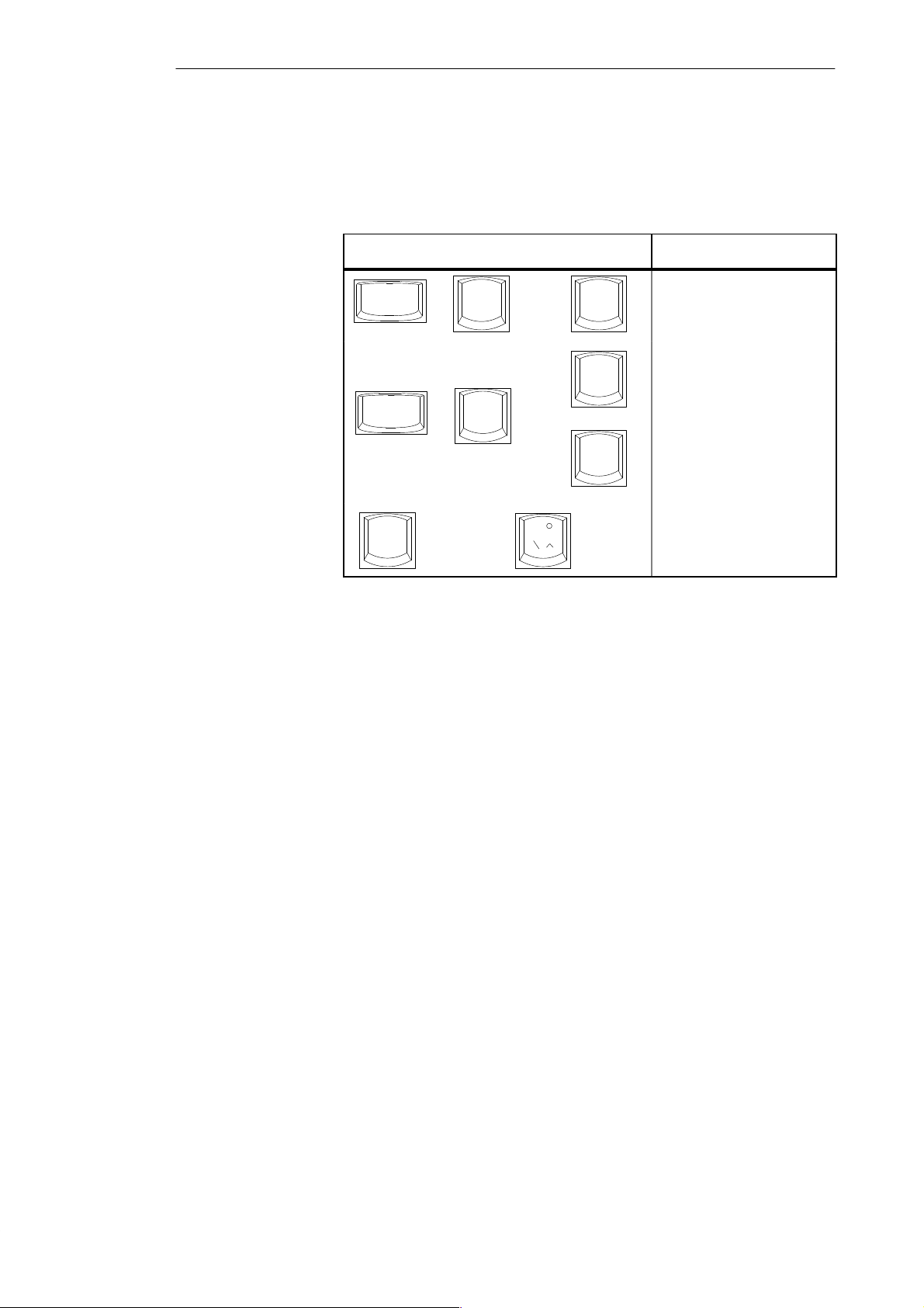
A selection of some of the most important key combinations are shown in the
following table.
Table 3-4 Key Combinations
Key Combination Effect
Ctrl
Ctrl
F
+
Alt
+
Alt
n
+
+
Delete
F1
+
F2
~
Restart
Switch over to international
character set
Switch over to German
character set: the German
keyboard driver must be
loaded.
Trackball active / passive
3-12
PG 720 P Programming Device
C79000-G7076-C721-02
Page 27

3.4 Trackball
Getting to Know the PG 720
Trackball
Cleaning the
Trackball
The trackball is a pointing device for cursor control and menu selection in
many programs that support mouse operation. By moving the trackball, the
cursor can be positioned anywhere on the screen.
By pressing the left-hand button, you set a marker. The function of the
right-hand button depends on the particular program you are using. You can
select objects or items in a menu and start functions with the trackball.
The trackball is in a roller housing which normally prevents dust collecting
on the ball or transmission mechanism. Nevertheless, you should clean the
trackball at regular intervals.
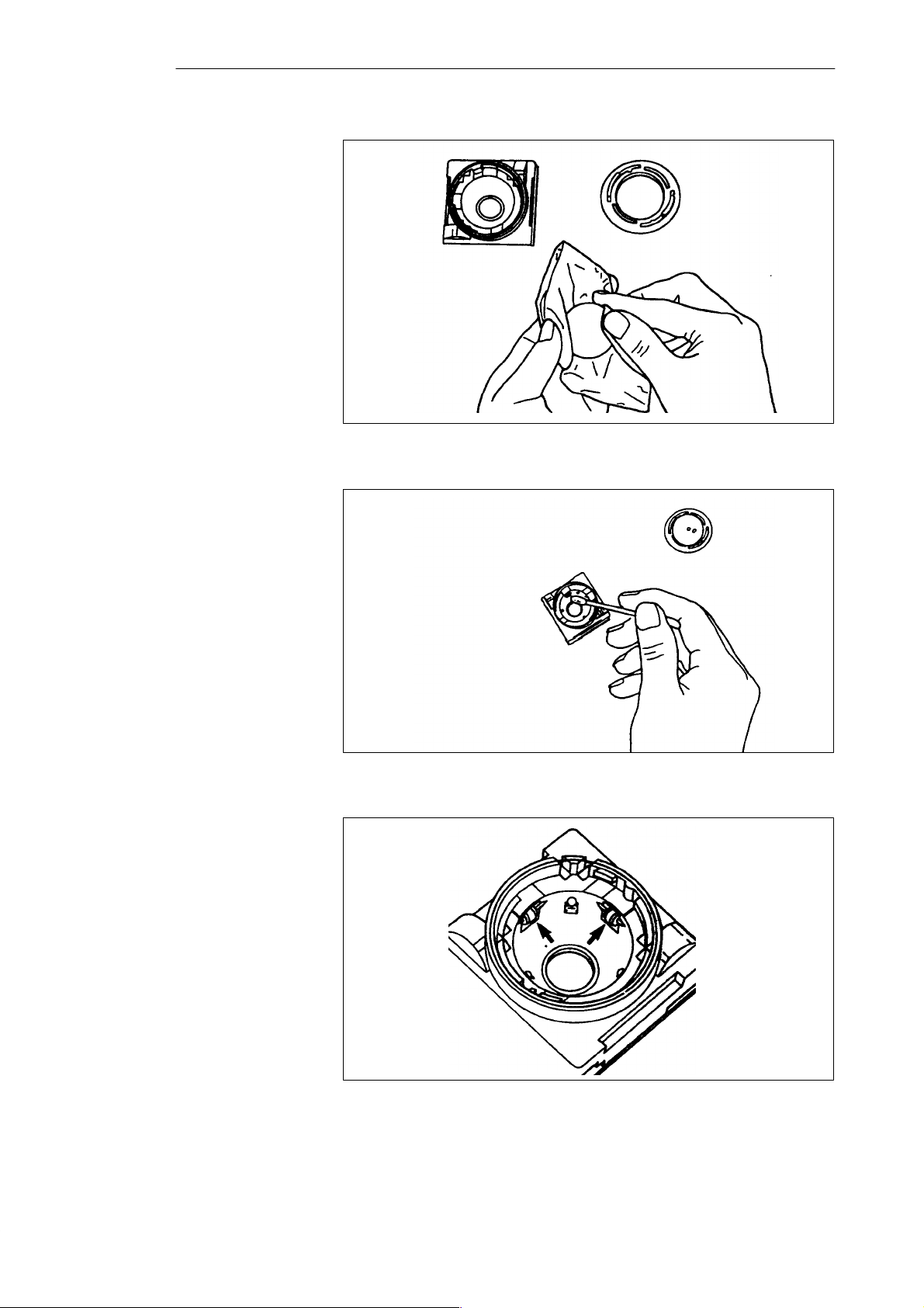
T o clean the trackball, proceed as follows:
1. Switch off your programming device.
2. Remove the cover of the trackball housing by turning it anti-clockwise,
for example by inserting tweezers or a similar tool into the holes in the
ring.
3. You can now take the trackball out of its housing.
4. Wash the trackball in a solution of tap water and mild cleansing agent.
5. Blow any residual dust out of the trackball housing.
6. Dry the trackball and return it to its housing.
7. Replace the cover and tighten it by turning it in a clockwise direction.
PG 720 P Programming Device
C79000-G7076-C721-02
3-13
Page 28
Getting to Know the PG 720
Figure 3-10 Cleaning the Trackball
3-14
Figure 3-11 Cleaning the Trackball Housing
Figure 3-12 Cleaning the Rollers
PG 720 P Programming Device
C79000-G7076-C721-02
Page 29
3.5 Drives
Getting to Know the PG 720
Drive Types
Floppy Disk Drive
Types of Diskette
The PG 720 is equipped with the following drives as standard:
Table 3-5 Standard Drives
Type of Drive Format Capacity
Floppy (diskette) drive 3.5 inch 1.44 Mbytes
Hard disk drive 2.5 inch See Product Bulletin
Using the floppy disk drive, you can save programs and data on diskettes and
load them on the PG 720.
You can use the following diskettes:
Table 3-6 Types of Diskette
Double-Sided High-Density Diskette Double-Sided Double-Density Diskette
3.5 inch 3.5 inch
1.44 Mbytes (135 TPI) 720 Kbytes
80 tracks per side 80 tracks per side
Handling Diskettes
!
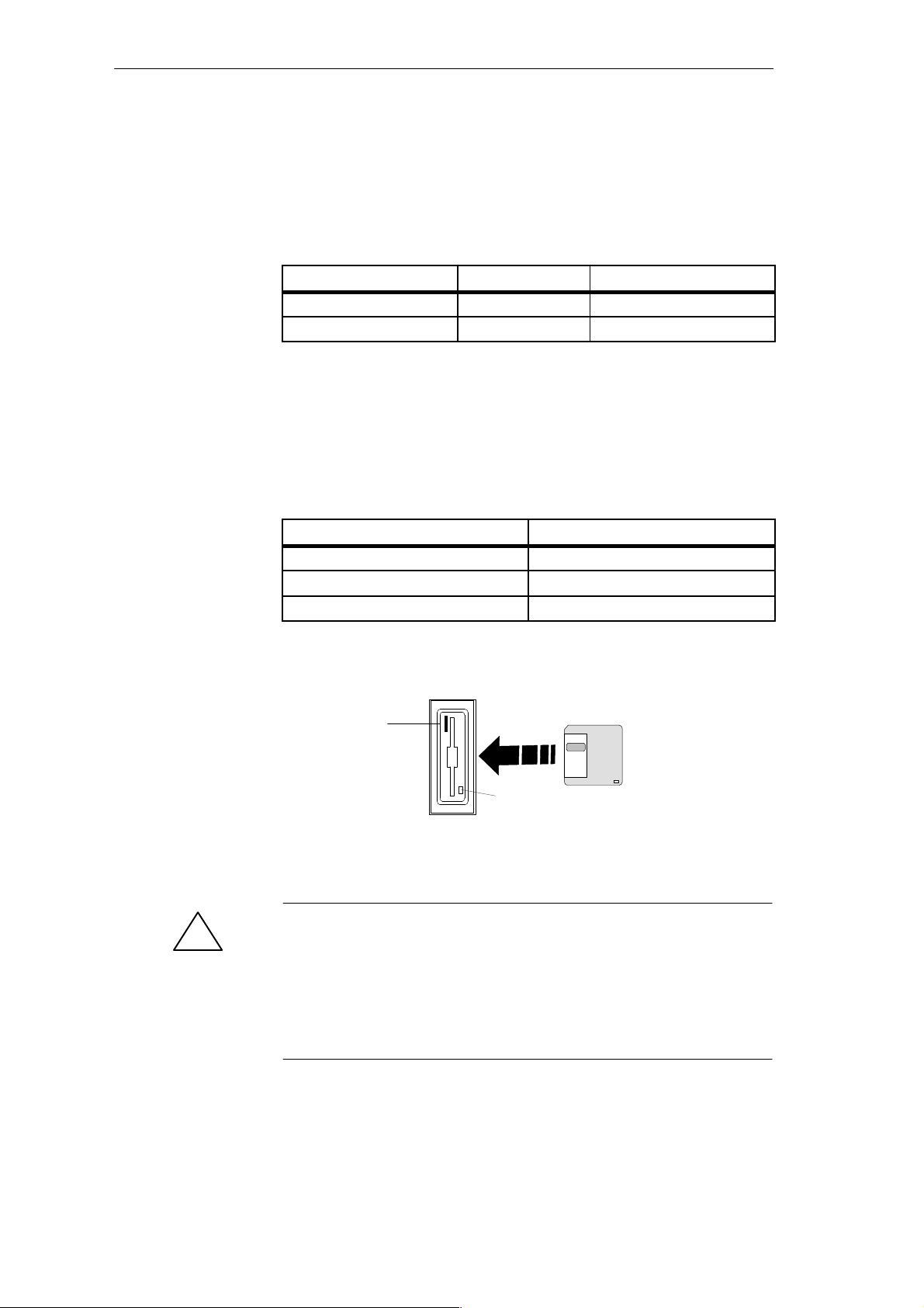
You insert diskettes into the drive as shown below:
Ejector
Access LED
The access LED for the floppy disk drive lights up on the front of the device
when the diskette is being accessed.
Caution
Risk of data loss!
You must not remove the diskette as long as the access LED is lit.
Otherwise, you may lose the data on the diskette.
Do not remove the diskette until the access LED on the drive or on the front
panel of the PG 720 has gone out.
PG 720 P Programming Device
C79000-G7076-C721-02
3-15
Page 30

Getting to Know the PG 720
Hard Disk Drive
!
CD-ROM Drive
You can use a number of different hard disk drives in your PG 720. The memory
capacity of the particular type of hard disk can be found in the Product
Information Bulletin and SETUP program.
Whenever the hard disk drive is accessed, the access LED on the front of the unit
lights up.
Caution
Risk of data loss and damage to drive!
Drives are sensitive to vibrations and shock. Any vibrations occurring during
operation can lead to the loss of data or damage to the drive.
After the operating system has been shut down, wait approximately 5
seconds before switching the device off. This allows the disk to come to a
complete stop and ensures optimal protection.
If you intend transporting the unit, switch it off, and wait until the drive has
come to rest (about 20 seconds) before you move it.
The CD-ROM drive enables you to read CDs. The drive is operated as a slave
parallel to the hard disk drive via the secondary IDE interface.
Self-T est
Caution
!
Risk of data loss and damage to the drive!
CD-ROM drives are sensitive to vibrations and shock. Any vibrations occuring
during operation can lead to damage to the drive or CD.
Whenever the PG 720 is switched on or reset, the hard disk drive runs
through a self-test which is repeated during operation.
3-16
PG 720 P Programming Device
C79000-G7076-C721-02
Page 31
3.6 CD-ROM Drive
Getting to Know the PG 720
Overview
Opening the
Drawer
Inserting /
Removing CDs
Closing the Drawer
You can use the CD-ROM drive to display information contained on CDs on
the PG 720. The CD-ROM drive is installed at the back of the PG 720. It is
operated on the same port as the hard disk drive.
Swing the PG 720 into a horizontal position. The CD-ROM drive is now on
the underside of the programming device. Switch the device on. By briefly
pressing the eject button, the drawer springs out slightly. Now pull the drawer
out until it clicks into position.
When you first open the CD-ROM drive, you will find a film sheet in the
drawer, to protect the drive during transport. Remove this sheet. Now insert
the CD in the drawer with the labeling face up, and press it firmly down into
the center of the turntable. T o remove the CD, hold it by the edges and pull
upwards.
Push in the drawer until it closes completely. Do not press the eject button.
Note
T o avoid too much pressure on the open drawer, always hold the drawer at
the front with one hand when inserting or removing a CD.
The EJECT function offered by various applications for opening the
CD-ROM drawer does not work with this drive.
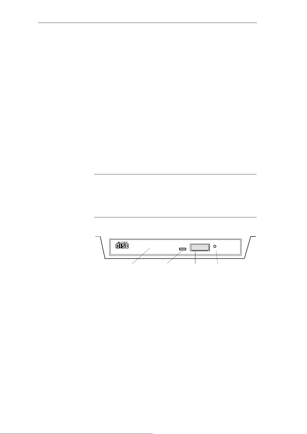
CD-ROM Front
1234
1 Access display
This display lights up when data are being read.
2 Drawer
This drawer can be opened and closed by hand.
The CD is inserted here.
3 Eject button
This button unlocks the drawer (2) for opening.
4 Emergency eject hole
PG 720 P Programming Device
C79000-G7076-C721-02
3-17
Page 32
Getting to Know the PG 720
3.7 External Power Unit and Battery
External Power
Unit
!
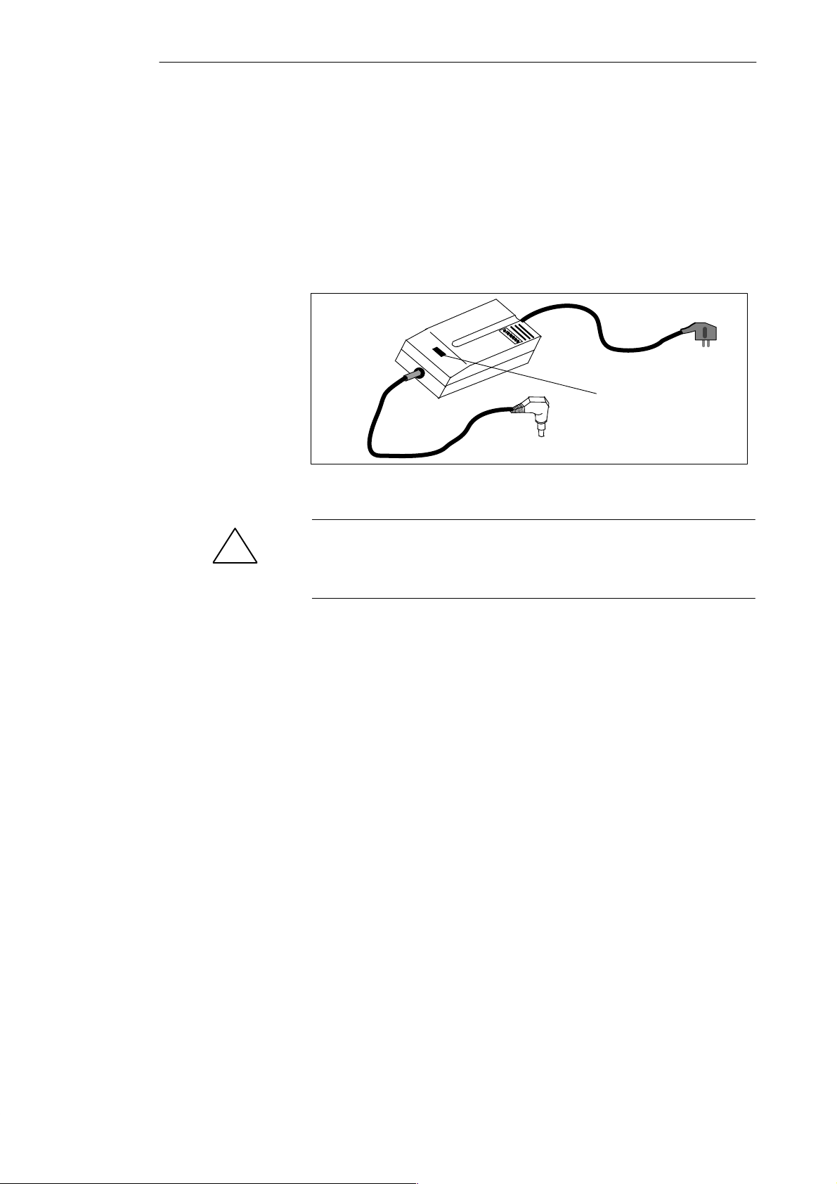
The external power unit is used to supply the PG 720 with power when it is
being operated with 115 V or 230 V mains supplies. The voltage range is set
automatically. In mains power supply operation, the integrated battery is
charged at the same time. The connecting cable to the PG 720 has an external
power supply unit. For connection to the power system, the external power
supply unit has a connector for non-heating appliances.
LED-Anzeige
Figure 3-13 External Power Supply Unit
Caution
Danger of overheating!
The external power supply unit can be damaged if it is covered.
Battery
The PG 720 has an integrated NiMH (nickel metal hydride) rechargeable
battery . This makes the device portable, meaning you can use it without the
external power supply. The battery also prevents data loss occurring on
power failure.
Once the external power supply unit is connected, the battery is charged. The
following conditions are important:
When charging, the battery temperature must be between + 5° C and
+ 40° C (40° F and 100° F).
When the device is switched off, charging takes approximately 2 hours
(fast charging).
When the device is switched on, charging takes approximately 6 hours
(reduced charging current).
Charging stops as soon as the battery is fully charged.
In storage, a fully charged battery runs down in approximately 2 months.
It must then be recharged.
3-18
PG 720 P Programming Device
C79000-G7076-C721-02
Page 33

Getting to Know the PG 720
Note
Whenever possible, avoid running down the battery too far . Switch off the
unit when it is not in use and remove the battery connector if it will not be
used for some time (weeks).
Before the battery is completely discharged, the red power LED lights up
and a warning signal is heard (see also Section 4.2).
PG 720 P Programming Device
C79000-G7076-C721-02
3-19
Page 34

Getting to Know the PG 720
3-20
PG 720 P Programming Device
C79000-G7076-C721-02
Page 35
Installing and Operating the PG 720
4
What Does This
Chapter Contain?
Chapter
Overview
This chapter describes what you have to do to set up your PG 720 correctly
for operation. This includes:
The basic steps for commissioning your PG 720
Working in the battery mode and changing the battery
Working with memory submodules and cards for the programmable logic
controllers
Connecting your PG 720 to other devices.
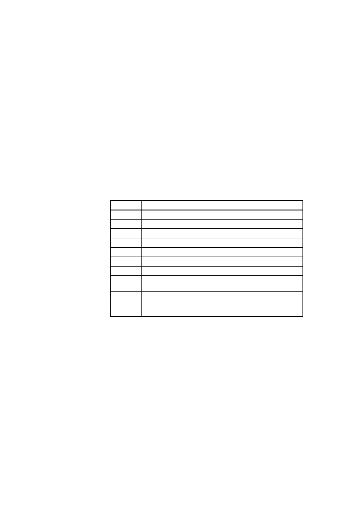
Section Contents Page
4.1 Connecting the PG 720 to the Power Supply 4-2
4.2 Battery Operation 4-3
4.3 Connecting I/O Devices 4-5
4.4 Working with SIMATIC S5 Memory Submodules 4-9
4.5 Working with SIMATIC Memory Cards 4-11
4.6 Working with PCMCIA Cards 4-12
4.7 Connecting the PG 720 to other SIMATIC S5 Units 4-13
4.8 Connecting the PG 720 to a SIMATIC S7 Network
(MPI/DP)
4.9 Networking the PG 720 with Other Stations on PROFIBUS 4-19
4.10 Networking the PG 720 and Other Computers on Industrial
Ethernet
4-17
4-20
PG 720 P Programming Device
C79000-G7076-C721-02
4-1
Page 36
Installing and Operating the PG 720
4.1 Connecting the PG 720 to the Power Supply
Connecting to the
Power Supply
You can operate the PG 720 on 115 V and 230 V power systems using the
external power supply unit. The voltage is selected automatically.
1. Plug the power supply cable supplied with the unit into the connector on
the external power supply unit.
2. Connect the power cable to a socket outlet with a grounded protective
conductor.
3. Connect the low voltage connector to the connection for the external
power supply on the unit. The power supply cable to the PG 720 is
integrated in the external power supply unit.
4. The device is now ready for power supply operation and the battery will
be charged if required.
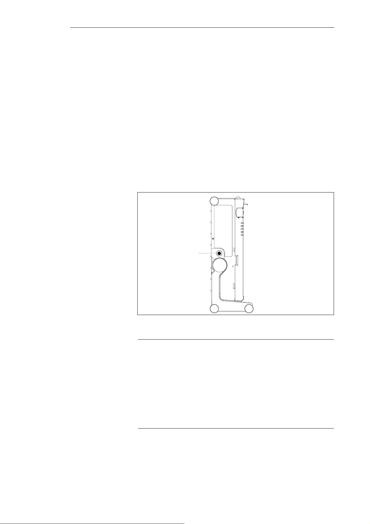
Connection for external
power unit
VN = 17.5 V DC
4-2
Figure 4-1 Power Supply Connection
Note
The power plug must be disconnected to isolate the unit completely from the
supply .
For operation in Canada and the US, a CSA or UL listed power supply cable
must be used.
The external power supply unit is intended for operation with grounded power
supply systems (TN networks according to IEC 364-3).
The unit is not intended for operation with non–grounded or
impedance-grounded systems (IT networks).
PG 720 P Programming Device
C79000-G7076-C721-02
Page 37

4.2 Battery Operation
Installing and Operating the PG 720
Battery Operation
If no external power supply unit is connected, you can operate the PG 720
using the integrated battery.
1. Switch on the device. Make sure that the battery is sufficiently charged
before you start work. The power LED is lit green as long as the battery is
sufficiently charged.
2. Work as normal with your PG 720.
3. As soon as the power LED lights up red in battery operation, this
indicates that the battery is almost run down. Stop working and save your
data.
Note
You should only begin working in the battery mode when the battery is
completely charged. Only then can you be sure that the full operating time is
available and that the battery running down will be indicated in good time. The
battery is fully charged when the power LED changes from charging (orange)
to charged (green) after switching on with the unit connected to the mains power
supply .
When you first start up, the battery may be partly or completely discharged (for
example, self-discharge). Connect the programming device to the power supply
using the power supply unit to charge the battery.
As soon as the device is connected to the external power supply, the connected
battery will be immediately recharged if it has been discharged. If the device
is switched off, this will take approximately 2 hours (fast charging); if the device
is switched on, the charging will take approximately 6 hours with reduced
charging current.
Replacing the
Battery
PG 720 P Programming Device
C79000-G7076-C721-02
You can replace a discharged or faulty battery with a fully charged spare
battery (for order number, see Product Information Bulletin) as follows:
1. Switch off the device.
2. Pull out the support from the stand and open out the extra support hoop.
3. Tilt the unit through approximately 90°.
4. Open the battery cover on the base of the device by pushing it down.
5. Disconnect the battery connections and remove the battery.
6. Insert the new battery and connect it.
7. Close the cover.
4-3
Page 38
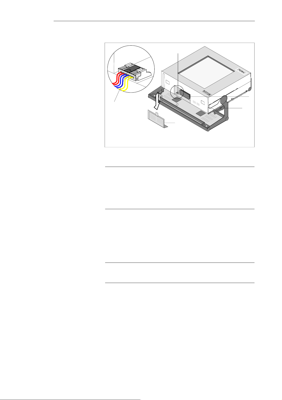
Installing and Operating the PG 720
Unlocking the
battery connector
- press here
1
2
3
4
Disposal of Used
Batteries
1 Battery connector
2 Battery
Figure 4-2 Changing the Battery
3 Support
4 Battery compartment cover
Note
Whenever possible, avoid running down the battery to a low level. Switch
off the device after use. If the device will not be used for some time (for
example, several weeks), you should remove the battery connector. The
battery then has no connection to the device and in this way can be optimally
saved for future use.
Nickel-metal hydride batteries can be recycled. Their components can be
used as raw materials for new batteries or other products. Effective recycling
of batteries is only possible when the used batteries are collected according
to type.
Note
4-4
Observe the local regulations for disposal of materials.
PG 720 P Programming Device
C79000-G7076-C721-02
Page 39
4.3 Connecting I/O Devices
Installing and Operating the PG 720
Recommended
Printers
Connecting the
Printer to the
Parallel Port
Siemens printers with a parallel interface and IBM character set are
recommended for use with the PG 720 programming device.
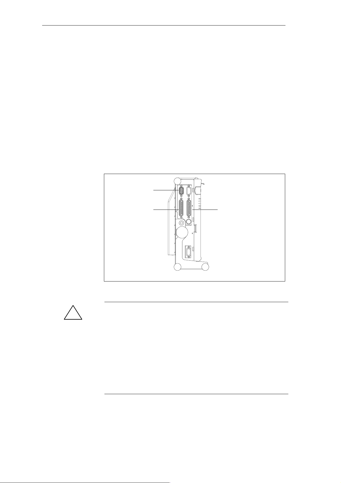
T o connect your printer, proceed as follows:
1. Switch off the PG 720 and the printer.
2. Open the cover to the interface ports on the left-hand side panel.
3. Plug the printer cable into the LPT1 parallel port.
4. Connect the printer cable to the printer.
5. Screw the connector tight at the interface port.
COM2 port
(serial)
COM1 port
(serial)
LPT1 socket
(parallel)
!
PG 720 P Programming Device
C79000-G7076-C721-02
Figure 4-3 The Printer Ports
Caution
Risk of damage to the unit!
Switch the unit off before connecting the parallel printer to the LPT 1 port
(the printer should also be switched off).
Make sure that you use the correct port. If you use the wrong port or
wrong connecting cables, the port may be damaged.
Before plugging in the cables, the electrostatic charge of your body, the unit,
and the cables must be equalized. T o do this, touch the mounting plate for the
ports on the left-hand side of the unit.
Only use original connecting cables.
4-5
Page 40
Installing and Operating the PG 720
Connecting the
Printer to the
Serial Port
Recommended
Monitors
Connecting
Monitors
You can also connect your printer to the PG 720 using a serial COM port. You
will find information on how to adapt and set your interface and which
connecting cable you require in the description of your printer .
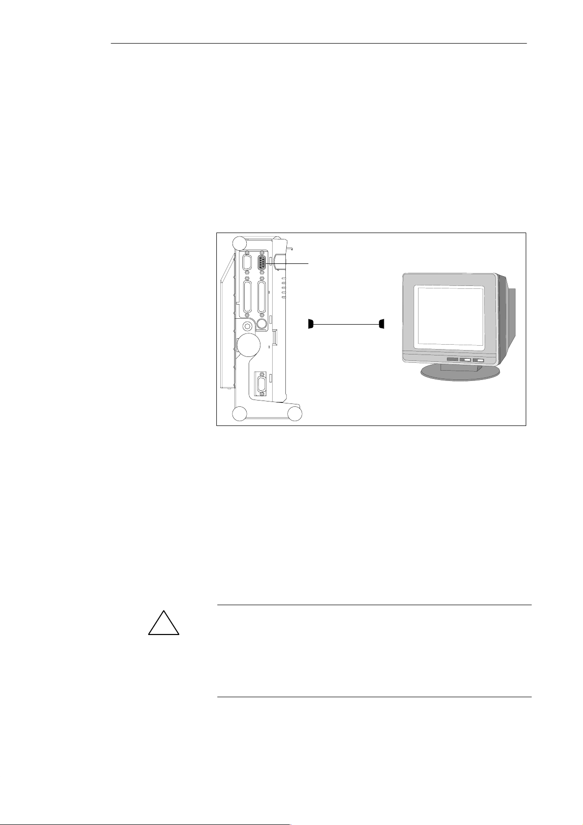
You connect external multisynchronous monitors using the standard VGA
connector on the left-hand panel side of the unit. We recommend that you use
a Siemens monitor.
You must switch the PG 720 off before connecting the monitor cable. You
will find further information about the connector pinout in Chapter 8.
VGA socket
Figure 4-4 Connecting the Monitor
T o connect the monitor, proceed as follows:
1. Switch off the PG 720 and the monitor.
2. Open the port cover on the left-hand side panel.
3. Plug the monitor cable into the VGA socket connector.
4. Secure the connector with the screws.
5. Plug the other end of the monitor cable into the monitor.
6. Switch on the PG 720 and the monitor.
7. Make the necessary changes in the SETUP program (menu “SIEMENS
PG 720 Hardware Control”, CRT/LCD selection: “Simultaneous” or with
high resolutions “CRT”).
Caution
!
Danger of damaging the monitor!
If you want to set higher clock frequencies and resolutions, first make sure
that the monitor you are using is suitable for a higher clock frequency and
resolution.
If the clock frequency is too high, this can cause damage to the monitor.
4-6
PG 720 P Programming Device
C79000-G7076-C721-02
Page 41
Installing and Operating the PG 720
Using a Mouse
Connecting a PS/2
Mouse
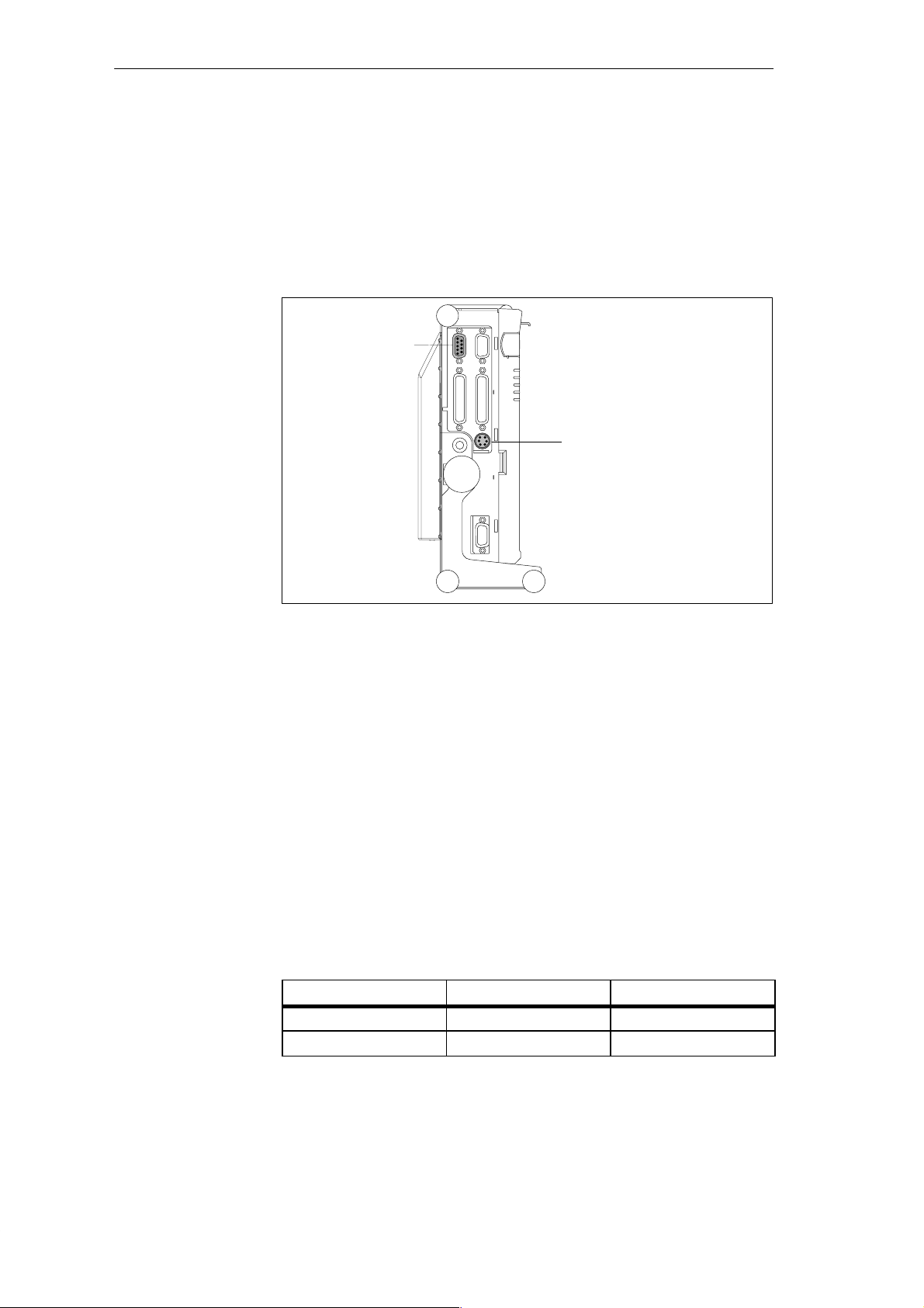
You can connect both a PS/2 and a serial mouse to the PG 720. When the
PG 720 is supplied, the mouse driver for the trackball and PS/2 mouse is
already loaded.
You can connect an external PS/2 mouse or another external pointing device
to an additional PS/2-compatible mouse connector.
COM2
Port for
serial mouse
(connector)
Port for
PS/2 mouse
(socket)
Switching between
Internal Trackball
and External PS/2
Mouse
Figure 4-5 Connecting a PS/2 Mouse
T o connect the mouse, proceed as follows:
1. Switch off your device.
2. Open the port cover on the left-hand side panel.
3. Plug the cable of the PS/2 mouse or another external pointing device into
the mouse connector.
4. Secure the connector with the screws.
5. Switch on your PG 720 again.
Once you have plugged in the external mouse and restarted your PG 720, the
internal trackball is deactivated and remains inactive until the PG 720 is
powered up again without the external mouse.
Table 4-1 Trackball/External Mouse Mode
State
No mouse Active
External mouse connected Deactivated Active
Internal Trackball External PS/2 Mouse
PG 720 P Programming Device
C79000-G7076-C721-02
4-7
Page 42
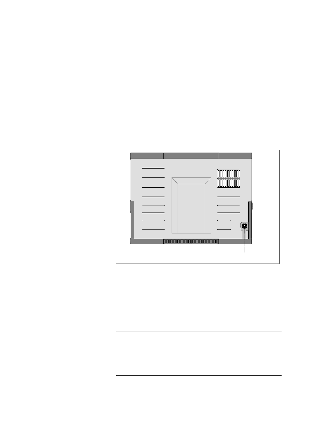
Installing and Operating the PG 720
Connecting a
Serial Mouse
Choosing Another
Keyboard
You can connect a serial mouse to the COM2 serial port. To operate a serial
mouse, the appropriate mouse driver must be initialized and assigned
parameters. You will find the information you need to do this in the
description of your mouse or in the description of the operating system.
1. Switch off your device.
2. Open the cover of the interface ports on the left-hand side panel.
3. Plug the serial mouse into the mouse connector labeled COM2.
4. Secure the connector with the screws.
5. Switch on your PG 720 again.
You can connect another PS/2-type keyboard to your PG 720 instead of the
one supplied with it.
Connecting a PS/2
Keyboard
4-8
Keyboard connection
Figure 4-6 Connecting a PS/2 Keyboard
T o connect the keyboard, proceed as follows:
1. Switch off your device.
2. Unplug the keyboard connector from the base of the unit.
3. Plug in the PS/2-type keyboard connector.
Note
It is advisable to use a keyboard cable with an angled connector, so that the
connector does not extend beyond the back panel.
The keyboard cable must be inserted in the cable conduit on the back panel
of the unit, otherwise the connector can work loose when the device is tilted.
PG 720 P Programming Device
C79000-G7076-C721-02
Page 43
Installing and Operating the PG 720
4.4 Working with SIMATIC S5 Memory Submodules
Working with
SIMATIC S5
Submodules
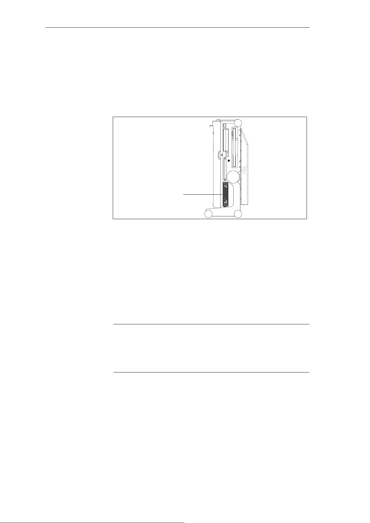
You can read and program SIMATIC S5 EPROMs and EEPROMs using the
48-pin S5 EPROM and EEPROM programming port. You will find
information about using the programming software in the STEP 5 User
Manual.
S5 EPROM/
EEPROM port
Figure 4-7 S5 Submodule (EPROM/EEPROM) Programming Port
Proceed as follows when working with the S5 submodule programming ports:
1. Switch on your device.
2. Start the EPROM function in your STEP 5 software (version V 6.x).
3. Plug the S5 memory submodule into the 48-pin programming port.
4. Read, program, or erase (EEPROMs only) your S5 memory submodule
with the EPROM programming package of your STEP 5 software.
5. Remove the S5 memory submodule.
6. T erminate the EPROM programming package of your STEP 5 software.
PG 720 P Programming Device
C79000-G7076-C721-02
Note
Only program SIMATIC S5 submodules when you are operating the device
using the power supply system (the external power supply unit must be
plugged in). Only then can you be sure that programming will not be
interrupted by a power outage if the battery is low.
4-9
Page 44

Installing and Operating the PG 720
Caution
!
Risk of damage to EPROMs or EEPROMs!
If you insert or remove the EPROM or EEPROM while it is in use, there is a
danger that it will be damaged.
You must not remove the S5 EPROM or EEPROM while the LED indicating
that the EPROM or EEPROM is being read etc. is lit. You cannot work
simultaneously with S5 memory submodules and memory cards.
Before inserting or removing S5 EPROMs or EEPROMs, you must equalize
the static charge on your body with the potential on the unit. You can do this
by briefly touching the metal mounting plate of the ports on the left-hand
side panel of the unit.
4-10
PG 720 P Programming Device
C79000-G7076-C721-02
Page 45
4.5 Working with SIMATIC Memory Cards
Installing and Operating the PG 720
Working with
SIMATIC Memory
Cards
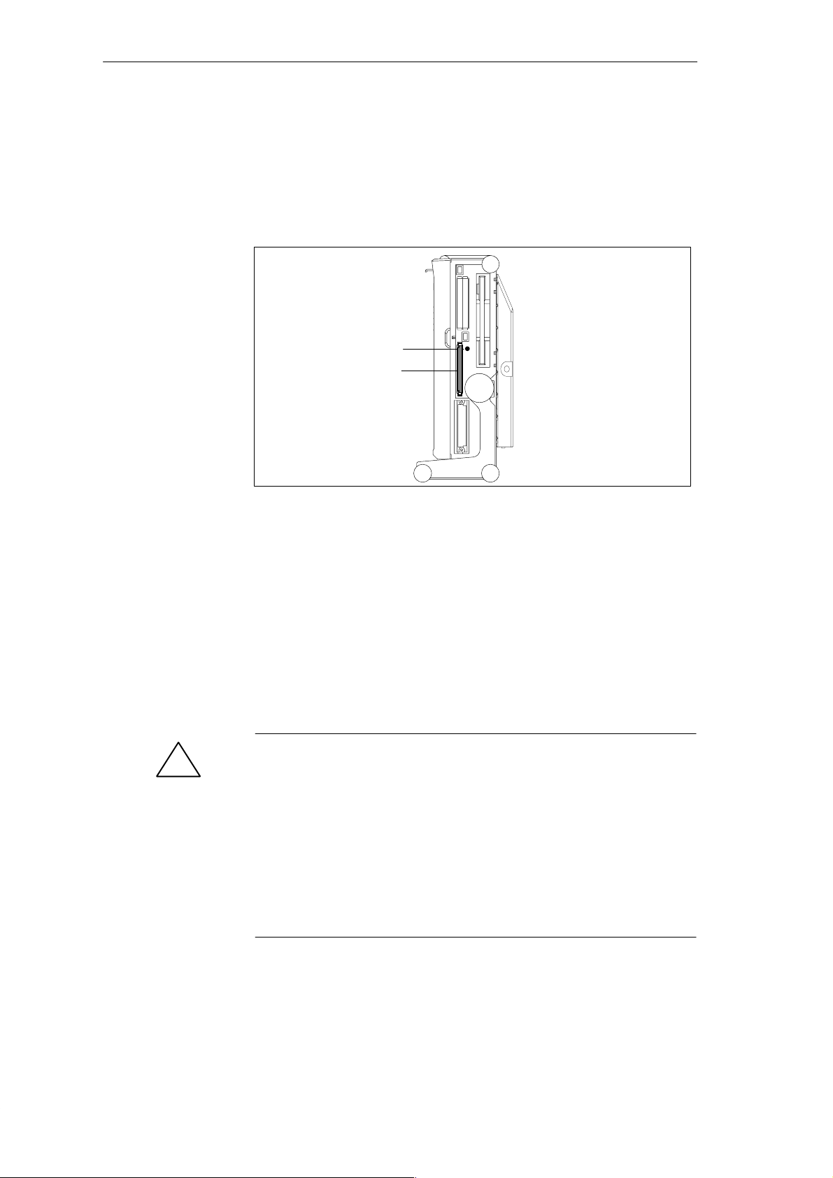
SIMATIC memory cards can be read, programmed, and erased using the
68-pin connector. SIMATIC memory cards are available for SIMATIC S5 and
SIMATIC S7 software.
Orientation point
SIMATIC memory cards
Figure 4-8 Slot for SIMATIC Memory Cards
Proceed as follows when working with SIMATIC memory cards:
1. Switch on your device.
2. Start your SIMATIC programming function.
3. Plug the SIMATIC memory card into the 68-pin connector.
4. Read, program, or erase the memory card with the programming function
of your SIMATIC programming software.
5. T erminate the programming function of your SIMATIC software.
6. Remove the SIMATIC memory card from the programming port for
further use in a programmable logic controller.
!
PG 720 P Programming Device
C79000-G7076-C721-02
Caution
Risk of damage to memory cards and the PG 720!
You must insert the memory card into the 68-pin connector with the type
label pointing to the rear of the unit. Make sure that the orientation point
beside the slot matches the point on the card.
If you attempt to plug in the memory card the wrong way round, you may
damage your PG 720 or memory card.
You must not remove the memory card while the LED indicating that the
card is being read etc. is lit. You cannot work simultaneously with S5
memory submodules and memory cards.
4-11
Page 46
Installing and Operating the PG 720
4.6 Working with PCMCIA Cards
PCMCIA Cards
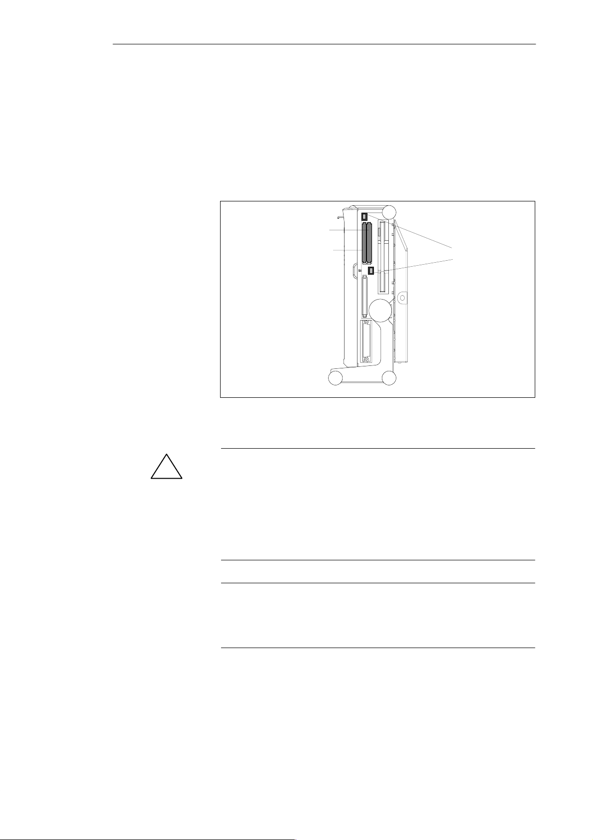
The PG 720 has two PCMCIA interface ports. You can plug communication
modules for MODEM, FAX-MODEM, ISDN, token ring, ETHERNET,
memory expansion, and SCSI interface modules in credit-card format into
this port. Either two cards of type II or one card of type III can be plugged in.
PCMCIA port type II
(Slot 1)
PCMCIA port type II/III
(Slot 2)
Figure 4-9 PCMCIA Port
Ejector for
PCMCIA cards
4-12
Caution
!
Risk of damage to the PCMCIA cards and the PG 720!
You must insert the PCMCIA card with the front side pointing the rear of
your PG 720. This side is generally labeled with a company or product
designation and the wording “this side up” or words to that effect.
If you attempt to insert the PCMCIA card the wrong way round, you may
damage your PG 720 and the PCMCIA card.
Note
PCMCIA cards must not be used along with a SIMATIC S5 memory
submodule or a SIMATIC memory card. Read the notes in your Product
Information Bulletin.
PG 720 P Programming Device
C79000-G7076-C721-02
Page 47

Installing and Operating the PG 720
4.7 Connecting the PG 720 to other SIMATIC S5 Units
Point-T o-Point
Connection
Configuring
Interfaces with
Line Current
(TTY, 20 mA)
Rules
In this section, you will learn how to connect your PG 720 to a programming
device or S5 programmable logic controller using a point-to-point
connection.
You can establish a point-to-point connection by connecting the PG 720 to
another programming device or a programmable logic controller using
An RS-232 connection
A TTY connection
T o ensure reliable data transfer, several factors must be taken into account.
You can reduce interference by choosing the right transmission cable and
connecting it properly, and by observing the following guidelines:
Use a shielded cable with a low line resistance (130 / km) (about 40
kft) and low capacitance (< 90 pF/m) (about 27 pF/ft). Twisted-pair cables
are less susceptible to noise and interference. A low line resistance results
in reduced voltage excursions and shorter charge reversal times. The line
resistance decreases with increasing conductor cross-section for the same
length of cable.
The shorter the transmission link, the higher the maximum possible data
transfer rate.
If there is an active sender and an active receiver at the same end of the
transmission link, the sequence of access priority to the transmission circuit
must be taken into account in order to achieve the longest possible
transmission link.
Signal lines and power lines must not run together. Signal lines must be
installed as far away as possible from sources of strong interference (for
example, 400 V 3-phase power cables).
The active TTY interface with a 12 V no-load voltage has been tested on a
100 m (1100 ft) long cable at a transmission rate of 9600 bps in an
environment with normal levels of noise (field strength < 3 V/m or 1 V/ft).
If a shielded LiYCY 5 x 1 x 0.14 shielded cable is used, reliable transmission
is possible over a distance of up to 100 m (1100 ft). The AS51 1 protocol (only
one transmitter at a time) was used for testing.
Note
The interference field of the source decreases exponentially with the
distance.
PG 720 P Programming Device
C79000-G7076-C721-02
4-13
Page 48
Installing and Operating the PG 720
Connecting the
PG 720 to S5
Programmable
Controllers
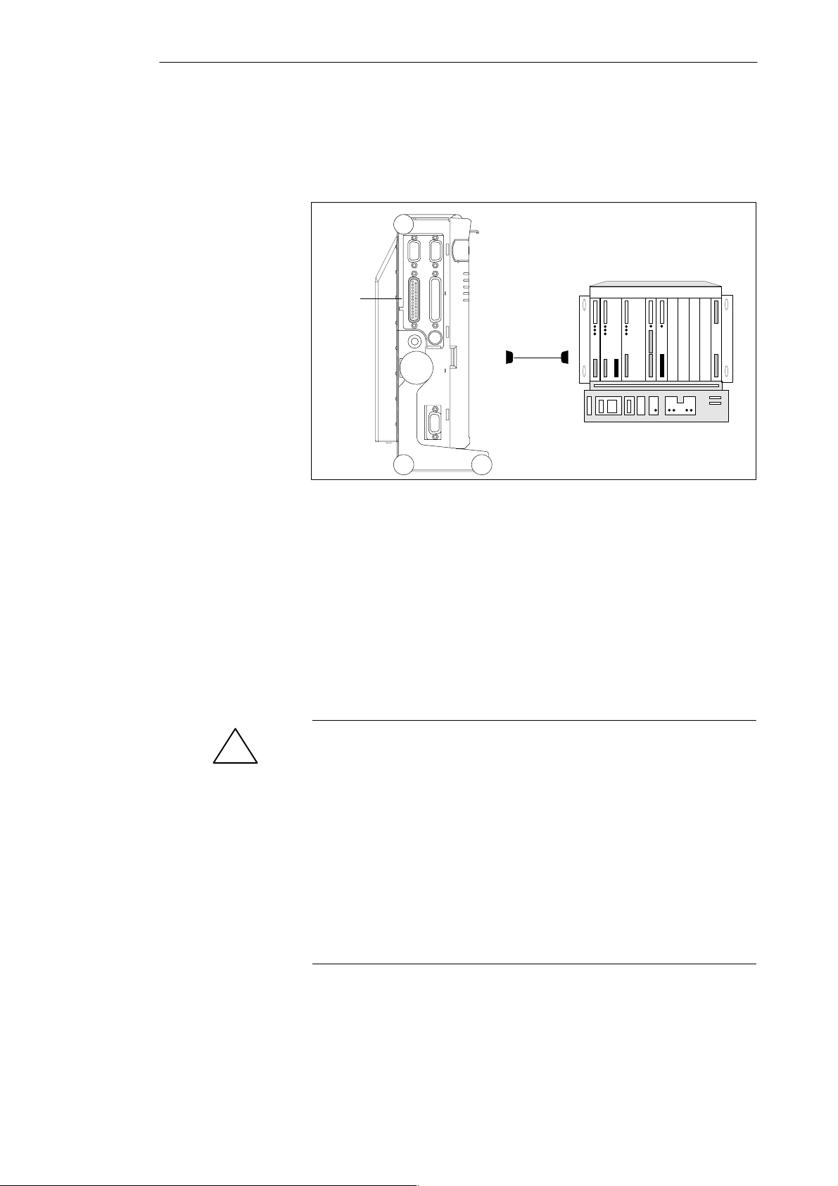
You can connect the PG 720 to a SIMATIC S5 programmable logic controller
using the COM1/TTY interface port. The cable for connecting to SIMATIC
S5 CPUs is supplied with the PG 720 (Order no.:6ES5734-2BD20).
COM 1
(socket)
Figure 4-10 Connecting the PG 720 to an S5 Programmable Logic Controller
You connect your PG 720 to a SIMATIC S5 programmable logic controller as
follows:
1. Switch off your device.
2. Open the cover of the interface ports on the left-hand side panel.
3. Plug the cable into the COM1/RS-232 modem/PLC interface port.
4. Secure the connector with screws.
5. Plug the cable into the corresponding port on the CPU of the
programmable logic controller.
Caution
!
Risk of damage to the PG 720!
The interface port may be damaged if you confuse the connections or use the
wrong connecting cables.
Make sure that the TTY cable of the PG 720 is plugged into the
COM1/TTY port and not into the LPT1 port.
Before plugging the cable in, the static charge on your body, the unit, and the
connecting cables must be equalized. You can do this by briefly touching the
metal mounting plate for the interfaces on the left-hand side panel of the
device.
Only use original cables to connect the programmable logic controller.
4-14
PG 720 P Programming Device
C79000-G7076-C721-02
Page 49
TTY interface
Installing and Operating the PG 720
Connecting the
PG 720 Using an
Adapter
Connecting the
PG 720 to Other
Programming
Devices
(RS-232, TTY)
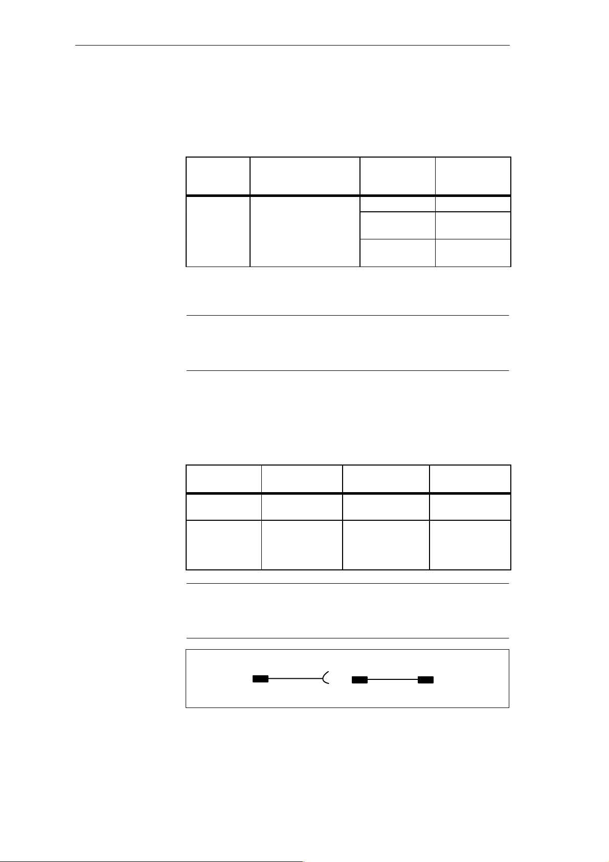
The connecting cable 6ES5 734-2BD20 is supplied with the PG 720. An
adapter is available for connecting the programmable logic controller using
older standard cables.
Table 4-2 Adapter for the PG 720 Connecting Cable
Port
COM1 as
Connection Connecting
PG 720 with SIMATIC S5
programmable logic
controller
Cable
Order No.
6ES5 734-2BD20
6ES5 731-1xxx0
15-pin
6ES5 731-0xxx0
25-pin
Adapter
6ES5 731-6AG00
6ES5 731-6AG00
T o allow a data transfer rate of 9600 bps up to a distance of 100 m (1100 ft), the
receiving diode is connected to ground (reference) via the connecting cable.
Note
Cables of various lengths are available under Order No. 6ES5 734-2xxx0
(xxx stands for the length in meters).
If you want to connect your PG 720 to another programming device, you can
plug the appropriate connecting cable into the RS-232 or TTY interface port.
You will find more detailed information about the connecting cables listed
below in Chapter 8.
Table 4-3 Connecting the PG 720 to Other Programming Devices
PG 720 P Programming Device
C79000-G7076-C721-02
Port
COM1 as
RS-232 interface
COM1 as
TTY interface
Connection Connecting cable
Order No:
PG 7xx with
PG 7xx
PG 7xx with
PG 6xx
6ES5 733-5BD20
Series connection of
6ES5733-2xxx0
and
6ES5731-6AG00
6ES5 731-6AG00
1)
Note
1)
When connecting the programming devices in series, make sure you
connect the cable the right way round (see Figure 4-11).
Adapter Connecting cable
PG 7XX
6ES5 731-6AG00 6ES5 733-2xxx0
Figure 4-11 Direction of Connection: Adapter-Connecting Cable
active passive
Adapter
PG 6XX
4-15
Page 50
Installing and Operating the PG 720
Note
If you connect two programming devices using the TTY interface, you must
deactivate the TTY interface (COM1) on one of the devices by changing the
jumper settings. When supplied, this interface is always active.
Activating/
Deactivating the
PG 720
Jumper Settings
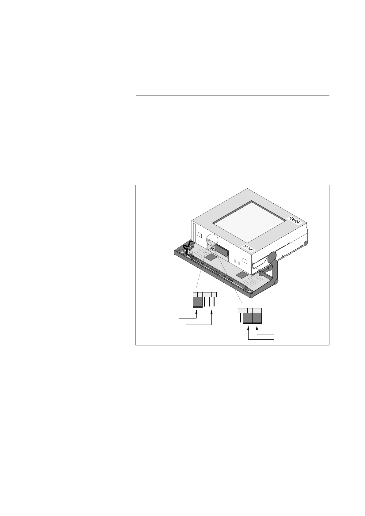
When your PG 720 is supplied, the COM1 (TTY) serial port is active (20 mA
current loop). When you connect two programming devices using the COM1
(TTY) serial port, you must deactivate the port on one of these devices. The
PG 720 has jumpers on the mother board for this purpose.
These jumpers are accessible if you open the battery compartment cover.
Change the jumper settings as shown in Figure 4-12.
deactivated
12345
Changing the
Jumper Setting
4-16
activated
12345
TTY receive
TTY send, open
TTY send
TTY receive
Figure 4-12 Activating/Deactivating the TTY Port Using Jumpers
Proceed as follows to deactivate the port on the PG 720:
1. Switch off your device.
2. Adjust the position of the PG 720 so that it is horizontal.
3. Open the battery compartment cover.
4. Remove jumpers 2-3 and 4-5 at the top left beside the battery.
5. Insert the jumper in slot 1-2 (see Figure 4-12).
6. Close the battery compartment cover.
PG 720 P Programming Device
C79000-G7076-C721-02
Page 51
Installing and Operating the PG 720
4.8 Connecting the PG 720 to a SIMATIC S7 Network (MPI/DP)
Connecting an S7
Programmable
Controller via an
MPI/DP Interface
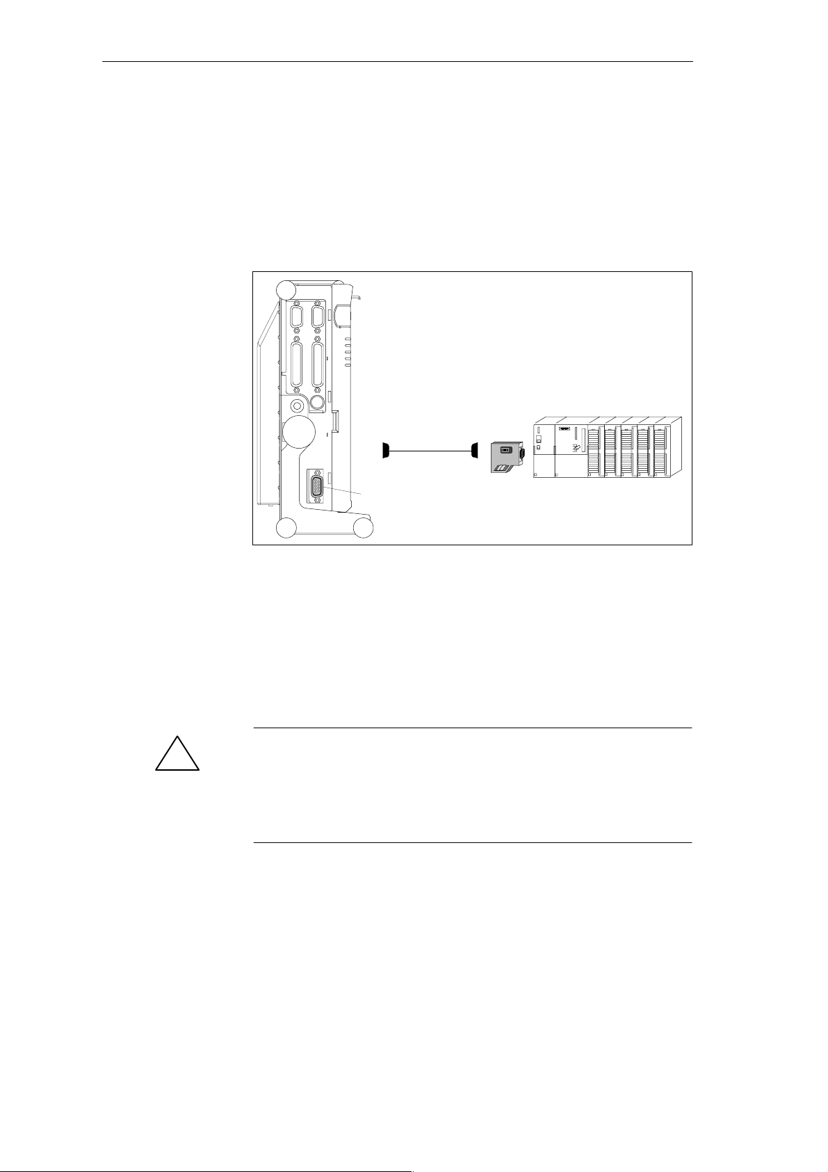
You can connect your PG 720 to a SIMATIC S7 programmable logic
controller using the floating MPI/DP interface. The MPI cable for connection
to SIMATIC S7 CPUs is supplied with the PG 720.
(Order No.:6ES7901-0BF00-0AA0)
In a high-interference area:
Bus connector
6ES5762-1AA21
6ES7901-0BF00-0AA0
5 m (about 16 ft.)
MPI/DP port
Figure 4-13 Connection Using the MPI/DP Interface
Connecting
Proceed as follows when connecting to a SIMATIC S7 programmable logic
controller:
1. Switch off your device.
2. Open the interface cover on the left-hand side panel of the device.
3. Connect the cable to the MPI/DP interface.
Caution
!
Risk of damage to the PG 720!
Before plugging in the cables, the static charge on your body, the unit, and
the cables must be equalized. You can do this by briefly touching the metal
mounting plate for the interfaces on the left-hand side panel.
Via the MPI/DP interface, you can connect your programming devices to
MPI networks (S7-200, S7-300, and S7-400) or
PROFIBUS DP networks (DP components).
The supplied MPI cable can be used for connection to MPI networks with
transmission rates up to 187.5 Kbps.
PG 720 P Programming Device
C79000-G7076-C721-02
4-17
Page 52

Installing and Operating the PG 720
MPI/PROFIBUS DP
Network
Up to 32 devices (PC, programming device, or programmable controller) can
be connected to the MPI/DP interface to form a network segment. The
physical connection to the MPI/PROFIBUS DP network is via a floating
RS485 interface which is a component of the programming device basic
module.
Several MPI/PROFIBUS DP network segments can be connected via
repeaters. The complete MPI/PROFIBUS DP network can comprise up to
127 stations. The data transmission rate in the MPI network is 187.5 Kbps.
Data transmission rates from 9.6 Kbps to 1.5 Mbps are possible in the
PROFIBUS DP via the MPI/DP interface.
Note
You can find information on setting up an MPI/DP network in the manual
“S7-300 Programmable Controller, Hardware and Installation”, Order No.:
6ES 7398-8AA01-8BA0.
4-18
PG 720 P Programming Device
C79000-G7076-C721-02
Page 53

Installing and Operating the PG 720
4.9 Networking the PG 720 with Other Stations on PROFIBUS
Networking the
PG 720 on
PROFIBUS
How the Network
Functions
Hardware
Requirements
PROFIBUS is an open and robust bus system for industrial use. It can be
used to configure networks with up to 32 stations per segment. The data
transfer rate for PROFIBUS is 1.5 Mbps.
The network operates on the master-slave principle with token passing
(complying with DIN19245, PROFIBUS). It distinguishes between active
and passive stations. An active station receives the token and passes it on to
the next station within a specified time.
Using the following components, for example, you can connect or network
the PG 720 with PROFIBUS:
PCMCIA interface module
RS485 interface (adapter for PCMCIA)
Shielded, twisted pair (bus cable or connecting cable to network).
Note
You will find more detailed information about the SINEC modules in the
SIMATIC NET Catalog IK 10.
For information about installing the modules and making modifications to
the network configuration, please refer to the installation instructions for the
appropriate modules.
Make absolutely sure that you do not use interrupt 12, since this interrupt is
assigned to the integrated trackball.
PG 720 P Programming Device
C79000-G7076-C721-02
4-19
Page 54

Installing and Operating the PG 720
4.10 Networking the PG 720 and Other Computers on Industrial Ethernet
Networking the
PG 720 on
Industrial Ethernet
How the Network
Functions
Hardware
Requirements
Industrial Ethernet is a bus system for industrial use based on ETHERNET
(ISO 8802/3). The main features of Industrial Ethernet are speed (10 Mbps),
simple expansion, open communication, and widespread application.
Industrial Ethernet is the name of Siemens networks and network
components operating according to the CSMA / CD (ETHERNET) principle.
Industrial Ethernet is a bus-type LAN that uses a triaxial cable (H1) as its
transmission medium.
T o connect or network the PG 720 with Industrial Ethernet, a
PCMCIA-ETHERNET interface module is required.
Note
You will find more detailed information about the SINEC modules in the
SIMATIC NET Catalog IK 10.
For information about installing the modules and making modifications to
the network configuration, please refer to the installation instructions for the
appropriate modules.
4-20
PG 720 P Programming Device
C79000-G7076-C721-02
Page 55
PG 720 Expansions
5
What Does This
Chapter Contain?
Chapter
Overview
You can enhance the performance of your PG 720 by adding additional
memory . This chapter describes how to expand your PG 720. Please observe
the relevant safety guidelines.
Section Contents Page
5.1 Opening the Unit 5-2
5.2 Components Visible After Opening the Unit 5-4
5.3 Switch Setting / Jumper 5-6
5.4 Installing Memory Expansion Modules 5-7
5.5 Replacing the Backup Battery 5-9
5.6 Closing the Unit 5-10
PG 720 P Programming Device
C79000-G7076-C721-02
5-1
Page 56
PG 720 Expansions
5.1 Opening the Unit
Prerequisites
!
Limitation of
Liability
The device is designed for easy maintenance so that any work that is
necessary can be done quickly and at low cost.
Caution
The electronic components on the printed circuit boards are extremely
sensitive to electrostatic discharge. Certain precautionary measures are
therefore necessary when handling such components. These measures are
explained in the guidelines for handling electrostatically-sensitive devices at
the end of this manual.
All technical specifications and licences apply only to expansion functions
approved by SIEMENS.
No liability can be accepted for impairment of functions caused by the use of
devices and components of other manufacturers.
All the modules and components in the PG 720 are electrostatically sensitive.
Please read the ESD guidelines at the end of this book carefully. The
following symbol warns that electrostatically-sensitive modules are present.
Before Opening
the Unit
Tools
5-2
Note the following rules before opening the unit:
Before you disconnect the power supply cable, discharge any electrostatic
charge on your body. You can do this by touching the metal mounting
plate for the interfaces on the left-hand side panel of the unit.
Discharge any electrostatic charge from tools that you are using.
Wear a grounding wrist-strap if you are handling components.
Leave components and modules in their packing until you are ready to
install them.
Disconnect the PG 720 from its power supply and remove the battery
before plugging in or removing any modules or components.
T ouch components and modules only on their edges. Above all, do not
touch the connecting pins and printed conductors.
Never operate the PG 720 with the cover open.
Use a screwdriver to open the unit.
PG 720 P Programming Device
C79000-G7076-C721-02
Page 57
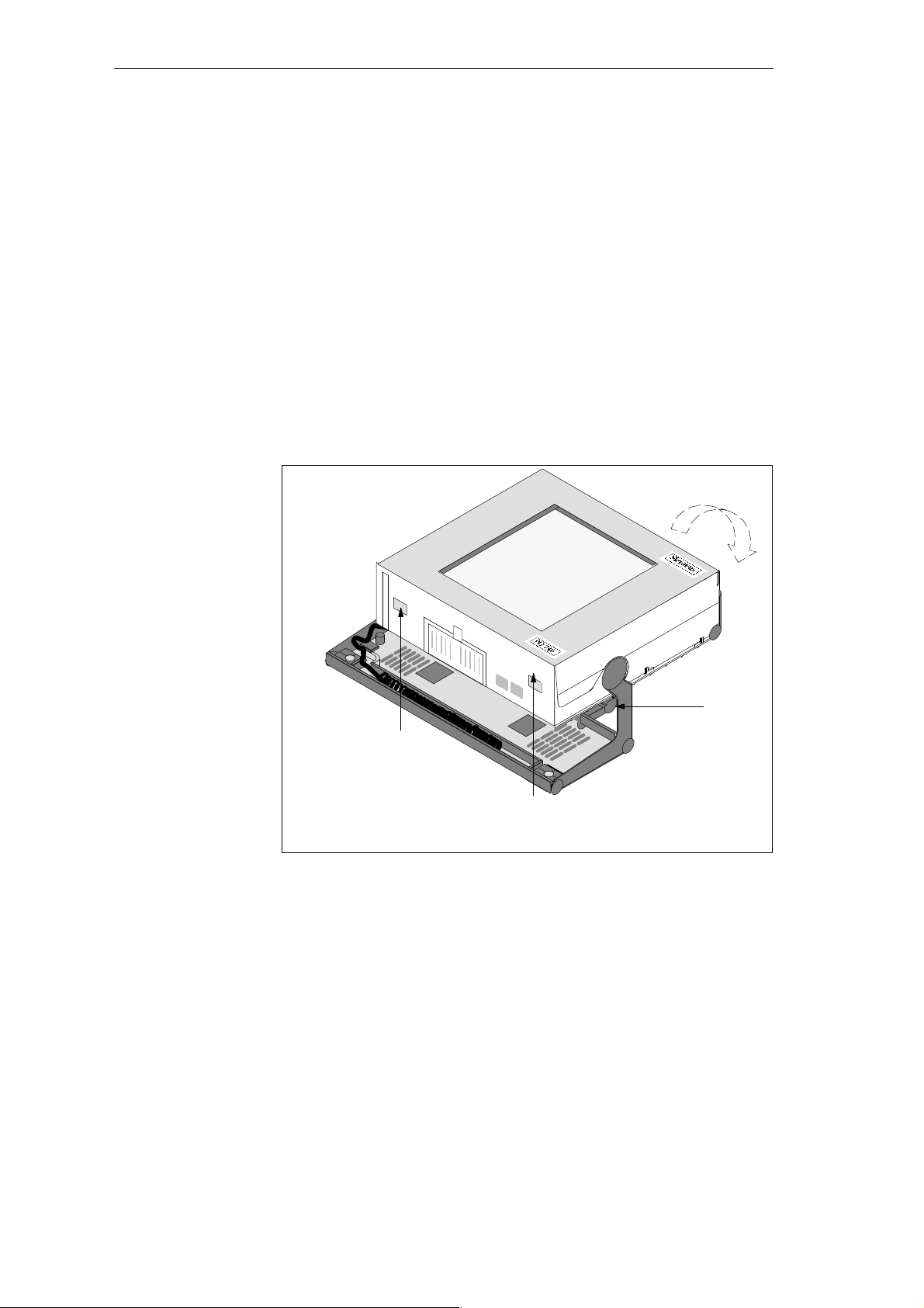
PG 720 Expansions
Opening the
PG 720
T o open your PG 720, proceed as follows:
1. Switch off the PG 720, pull out the power supply connector, and remove
all connecting cables from the unit, including the keyboard cable.
2. Lower the keyboard and detach it.
3. Incline the unit to 90°. T o stabilize the unit, pull out the extra support and
the fold-down bracket.
4. Open the cover of the battery compartment and disconnect the battery.
5. Push in the snap catches at the bottom with a small screwdriver.
6. Open the front section and lift it out of the main casing.
7. Remove the CD-ROM ribbon cable from the drive connector on the
backplane.
8. Lay the front section with the display on a soft, flat surface.
2
Snap catches on the base of the unit
Figure 5-1 PG 720 Prepared for Opening
Pull-out support
PG 720 P Programming Device
C79000-G7076-C721-02
5-3
Page 58
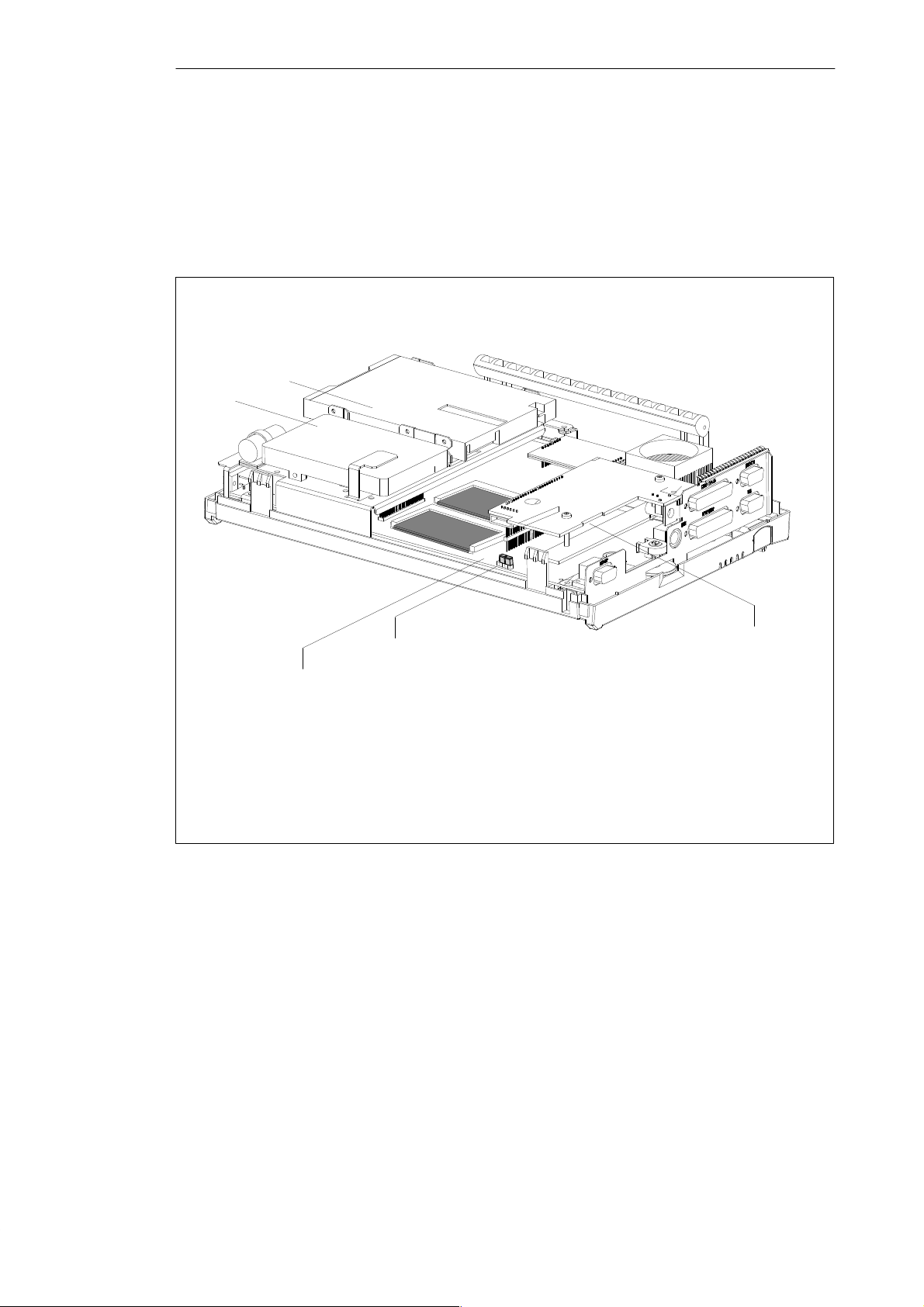
PG 720 Expansions
5.2 Components Visible After Opening the Unit
Components
Once you have removed the top cover of your unit, the components are
visible.
1
3
4
2
1 Drives
2 Mother board
Figure 5-2 PG 720 Opened
3 Power supply
4 Jumpers for TTY setting
5-4
PG 720 P Programming Device
C79000-G7076-C721-02
Page 59
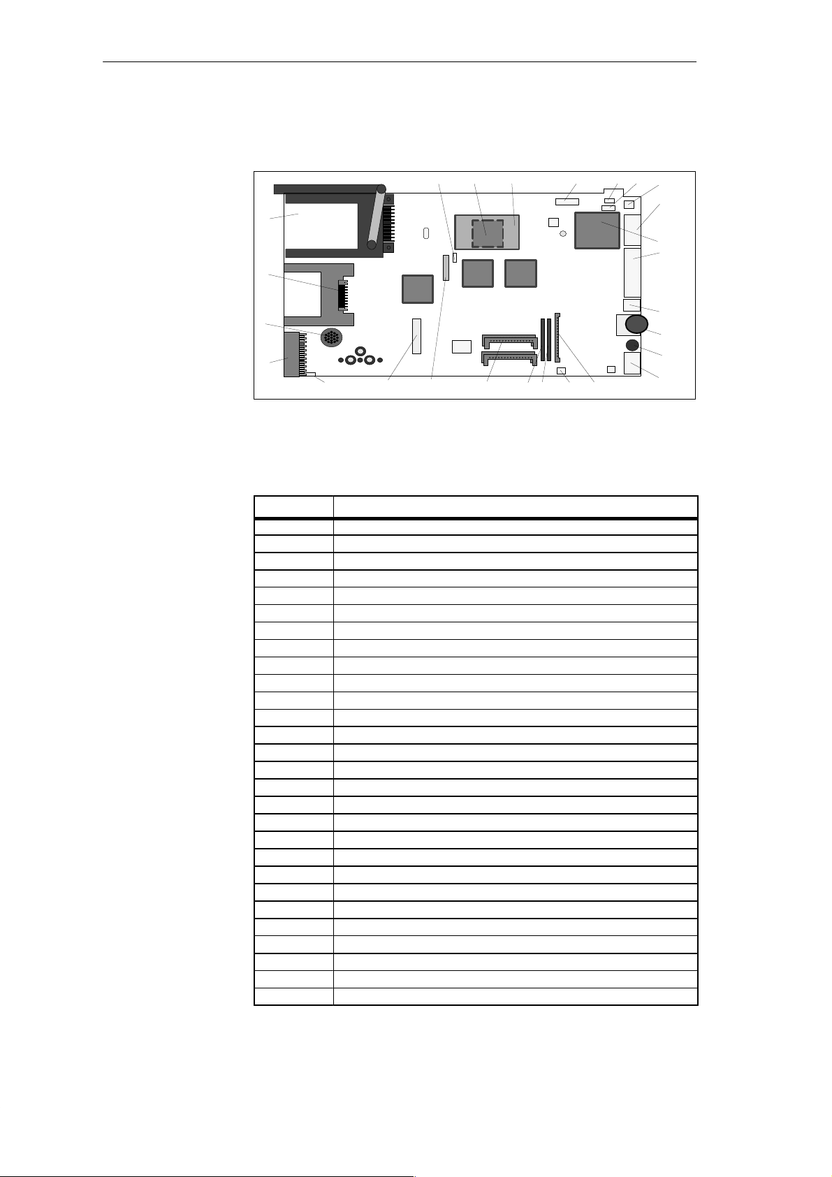
PG 720 Expansions
Mother Board
Components on
the Mother Board
The mother board is the heart of the PG 720. Here, data are processed and
stored, and interfaces and device I/Os controlled and managed.
27
2628222324
1
3
4
2
16
Figure 5-3 Mother Board
19 2021
6
11 12
9
The following components are located on the mother board of the PG 720:
Table 5-1 Components of the Mother Board
No. Function
1 PCMCIA slots
2 S5 submodule port
3 Memory card port
4 Loudspeaker
5 CPU on base with cooling unit
6 System memory, slot 0, slot 1, slot 2, slot 3
7 External VGA connection
8 COM2 serial port
9 TTY jumpers (X30)
10 COM1/TTY serial port
11 TTY receiver
12 TTY transmitter
13 MPI port
14 LPT1 parallel port
15 PS/2 mouse connection
16 Battery connector
17 Contrast
18 Keyboard and trackball connection
19 Floppy disk drive connection
20 Power supply connection (from DC converter)
21 IDE Winchester connector and CD-ROM
22 Voltage transformer for CPU, installed
23 Jumper on base of transformer
24 Clock setting (switch S1)
25 Connector for processor ventilator
26 Connector for switch
27 Connector for display unit
28 Connector for display
25
7/8
5
10/14
15
17
18
13
PG 720 P Programming Device
C79000-G7076-C721-02
5-5
Page 60
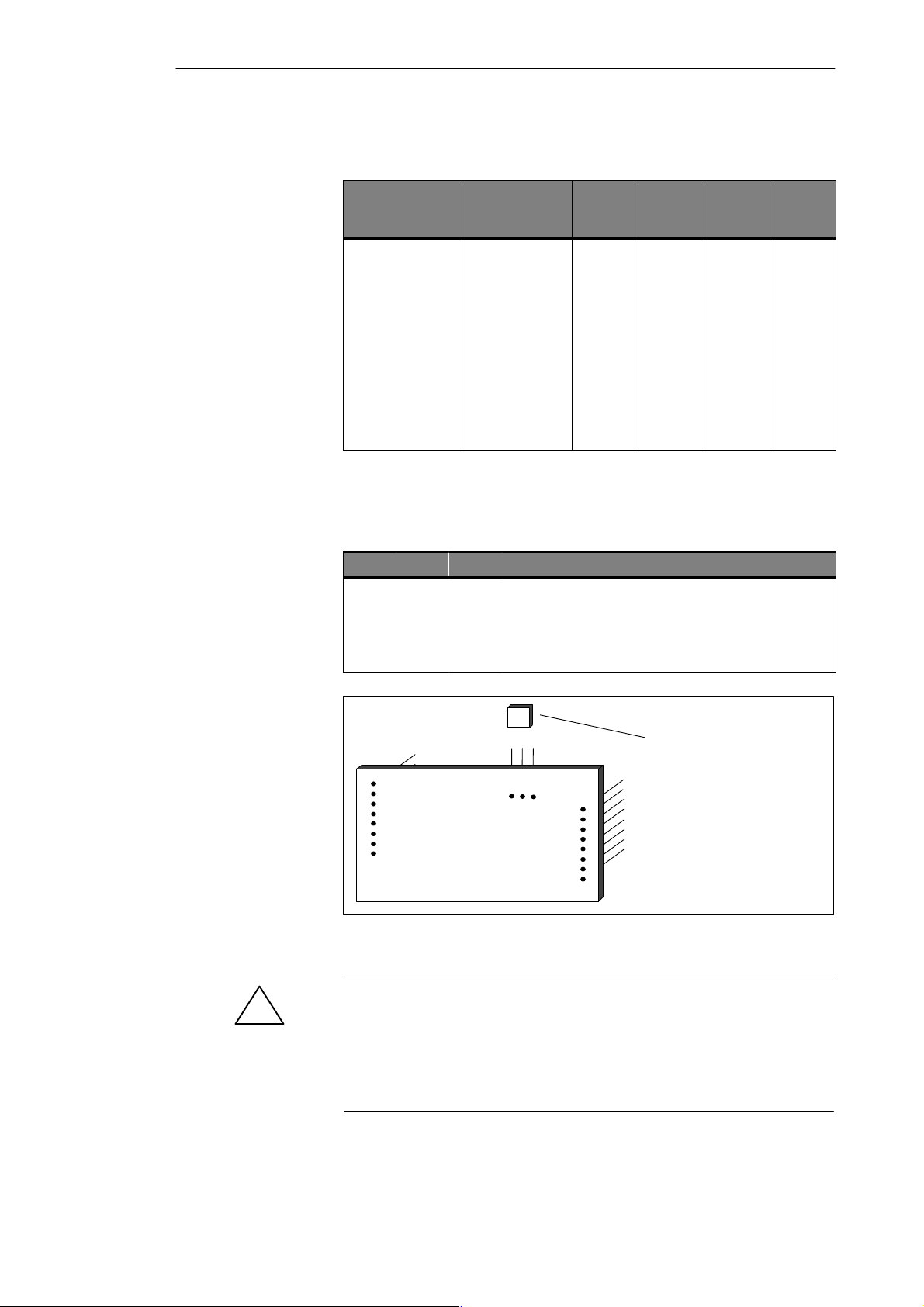
PG 720 Expansions
5.3 Switch Setting / Jumper
Clock Setting
(Switch S1)
TTY Jumpers
(x30)
CPU-Cuore
Frequency
(CPU-Internal)
233 MHz 66 MHz * ON * OFF * OFF * OFF *
200 MHz 66 MHz ON OFF OFF ON
166 MHz 66 MHz ON OFF ON ON
150 MHz 60 MHz OFF OFF ON ON
133 MHZ 66 MHz ON OFF ON OFF
120 MHz 60 MHz OFF OFF ON OFF
100 MHz 60 MHz OFF ON ON OFF
100 MHz 50 MHz ON OFF OFF OFF
90 MHz 60 MHz OFF OFF OFF OFF
75 MHz 50 MHz OFF ON OFF OFF
CPU Bus
Frequency
S1/1 S1/2 S1/3 S1/4
* Default setting
The PCI bus frequency is generated asynchronously and is fixed at 33 MHz.
The ISA bus frequency is derived from the PCI frequency and is always
8.25 MHz.
X30 Function
2-3 4-5 Active TTY port (standard setting)
x off TTY send loop separate from power source (passive
off x TTY receive loop separate from power source (passive
setting)
setting)
Jumper Setting
5-6
321
Figure 5-4 Transformer for CPU with Jumpers
Jumper
Transformer Transformer
Type 1 Type 2
1–2 2.9V 2.1V
2–3 3.1V 2.2V
* Default setting
(depending on processor type
and transformer type)
Caution
!
Only special processors are suitable for use in the PG 720. The CPU requires
a special supply voltage. The appropriate transformer must be used with the
correct jumper setting.
Before upgrading, you are strongly advised to contact the Customer Support
team.
PG 720 P Programming Device
C79000-G7076-C721-02
Page 61
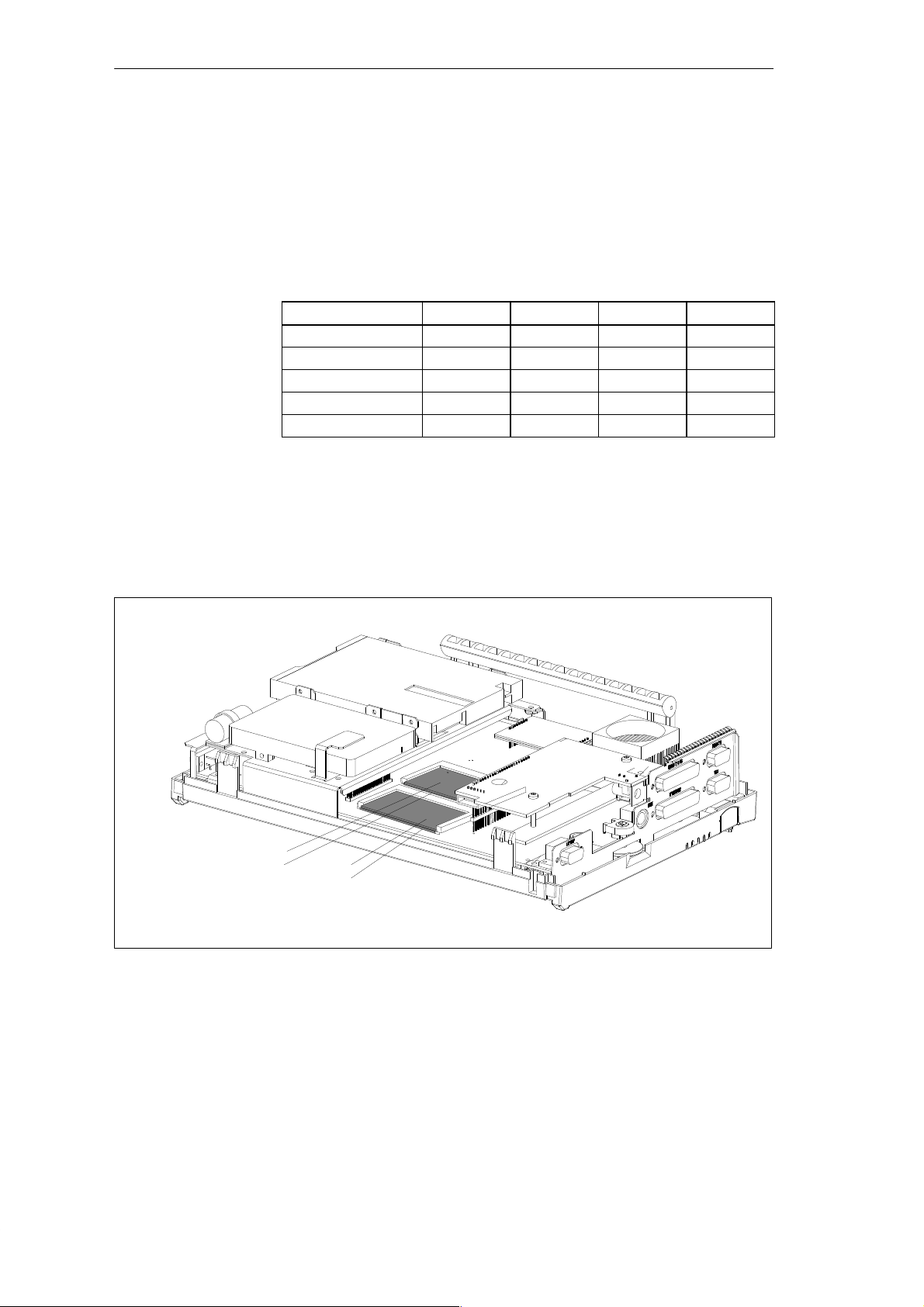
5.4 Installing Memory Expansion Modules
PG 720 Expansions
Standard Memory
There are four slots on the mother board for DIMM memory submodules. This
allows you to expand the memory capacity of your PG 720 to up to 128 MB.
Table 5-2 Slots for Memory Expansion (Double Base)
Memory
32 MB 16 MB 16 MB – –
64 MB 16 MB 16 MB 16 MB 16 MB
64 MB 32 MB 32 MB – –
96 MB 32 MB 32 MB 16 MB 16 MB
128 MB 32 MB 32 MB 32 MB 32 MB
Slot 0 Slot 1 Slot 2 Slot 3
The memory submodules must always be inserted in pairs (slot 0, 1 or
slot 2, 3).
You will find the order numbers for the DIMM memory expansion
submodules in the Product Information Bulletin.
Slot 0
Slot 2
Figure 5-5 Position of the DIMM Memory Submodules
PG 720 P Programming Device
C79000-G7076-C721-02
Slot 1
Slot 3
5-7
Page 62

PG 720 Expansions
!
Caution
Risk of damage!
The electronic components of the printed circuit boards are extremely
sensitive to electrostatic discharge. Certain precautionary measures are
therefore necessary when handling such components. These measures are
explained in the guidelines for handling electrostatically-sensitive devices at
the end of this manual.
Installing the
DIMM Cards
!
Installation
T o plug in expansion submodules, proceed as follows:
1. Open the unit as described in Section 5.1.
2. Plug the cards into the slots. Note the safety recess on the connector side
of the DIMM card.
3. Push the card down applying light pressure until it locks into place.
4. Close the unit (see Section 5.6).
Caution
Risk of damage!
Make sure that the cards sit securely in the slots, otherwise they can fall out
and be damaged.
The memory configuration is detected automatically. When you switch on
the unit, the distribution of base and extended memory is displayed on the
screen.
5-8
PG 720 P Programming Device
C79000-G7076-C721-02
Page 63
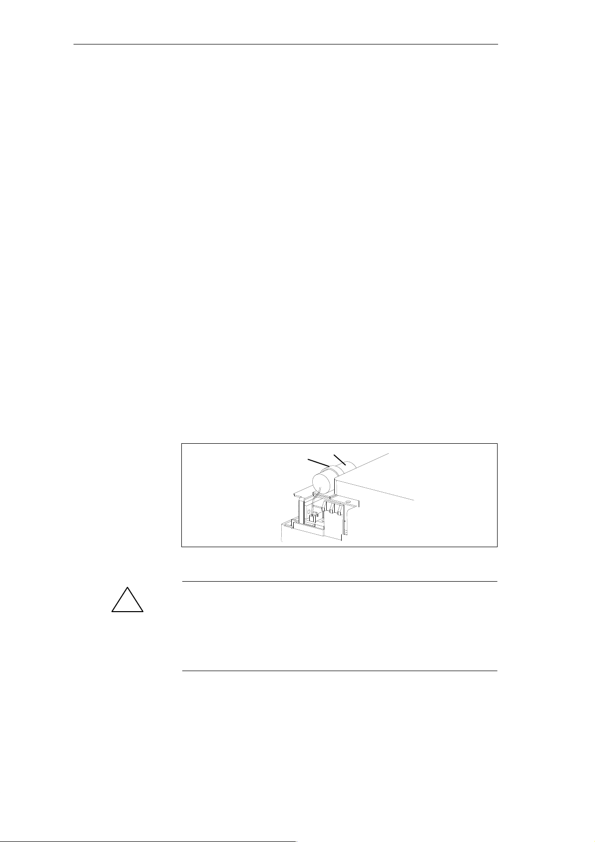
5.5 Replacing the Backup Battery
PG 720 Expansions
Battery Power
Supply for
Real-Time Clock
and Configuration
Battery V oltage
too Low
Replacing the
Battery
A backup battery (3.6 V lithium battery) powers the real-time clock even
after the PG 720 is switched off. In addition to the time of day, all the
information about the PG 720 (device configuration) is stored in RAM. If the
backup battery fails or is removed, all these data are lost.
The clock uses very little power and the lithium battery has a high capacity
so that the battery can provide backup power for the real-time clock for many
years and seldom needs to be replaced.
If the battery voltage is too low, the time of day and the device configuration
data in the RAM are lost.
In this case, you must replace the backup battery. The battery is located on
the drive mounting.
T o change the battery, proceed as follows:
1. Switch off your PG 720 and remove the power cable and all the connecting
cables.
2. Open the unit as described in Section 5.1.
3. Now change the battery by removing the connector and releasing it from the
clip.
4. Push the new battery firmly into the clip.
5. Close the unit as described in Section 5.6.
!
Changing SETUP
Clip
Figure 5-6 Clip for Backup Battery
Caution
Risk of damage!
Only replace the lithium battery with an identical battery or with a type
recommended by the manufacturer (Order No.: W79084-E1003-B1).
Dispose of used batteries in keeping with local regulations.
After you have changed the battery, you must set the configuration data of
your unit again using the SETUP program (see Chapter 6).
Backup battery
Hard disk drive
PG 720 P Programming Device
C79000-G7076-C721-02
5-9
Page 64

PG 720 Expansions
5.6 Closing the Unit
Closing the Unit
T o close the unit, proceed as follows:
1. Tilt the unit to the horizontal position.
2. Place the front section on the casing at an angle (the guide studs at the top
edge must fit into place).
3. Insert the CD-ROM ribbon cable into the drive connector on the
backplane.
4. Press the front section onto the lower edge of the casing until the catches in
the base engage.
5. Insert the battery into the battery compartment and connect it up.
6. Close the battery cover.
7. Connect the keyboard connector to the back of the unit. Make sure that
the cable is inserted in its channel.
8. Insert the keyboard cable in the cable conduit at the base of the device.
9. Allow the keyboard hinge to slide into the receptacles in the base of the
device.
10.Tilt the unit back into the operating position.
Your PG 720 is now ready for operation again.
5-10
PG 720 P Programming Device
C79000-G7076-C721-02
Page 65
Configuring the PG 720
6
What Does This
Chapter Contain?
Chapter
Overview
In this chapter, you will learn how to configure your programming device.
You need to do this if you change your system by adding, removing, or
exchanging expansion modules and memory expansions, or by replacing a
system module.
Section Contents Page
6.1 Changing the Device Configuration with SETUP 6-2
6.1.1
6.1.2
6.1.3
6.1.4
6.1.5
6.2
The Main Menu 6-5
The Advanced Menu 6-14
The Security Menu 6-16
The Power Savings Menu 6-17
The Exit Menu 6-19
Configuring the PCMCIA Interface 6-22
PG 720 P Programming Device
C79000-G7076-C721-02
6-1
Page 66

Configuring the PG 720
6.1 Changing the Device Configuration with SETUP
Changing the
Device
Configuration
SETUP
Program
Incorrect SETUP
Data
Starting SETUP
Your PG 720 device configuration is set for working with the software
supplied with the unit. You should only change the preset values if you have
modified your PG 720 in any way or if a fault occurs when the unit is
powered up.
The SETUP program is in the ROM-BIOS. Information about the system
configuration is stored in the battery-backed RAM of the PG 720.
You can use SETUP to set the hardware configuration (for example, hard
disk type) and define the system characteristics. You can also use SETUP to
set the time of day and date.
If incorrect SETUP data are detected when you boot the system, the BIOS
prompts you to:
Start SETUP by pressing F2 or
Continue booting by pressing F1.
On completion of the startup test, the BIOS gives you the opportunity of
starting the SETUP program by displaying the following screen prompt:
PRESS <F2> to enter SETUP
SETUP Menus
T o start SETUP, proceed as follows:
1. Reset your PG 720 (warm or cold restart).
2. Press the F2 key as long as the BIOS prompt appears on the screen.
The various menus and submenus are listed on the following pages. You can
get all the information you need for the SETUP entry selected from the
“Item Specific Help” part of the relevant menu.
6-2
PG 720 P Programming Device
C79000-G7076-C721-02
Page 67
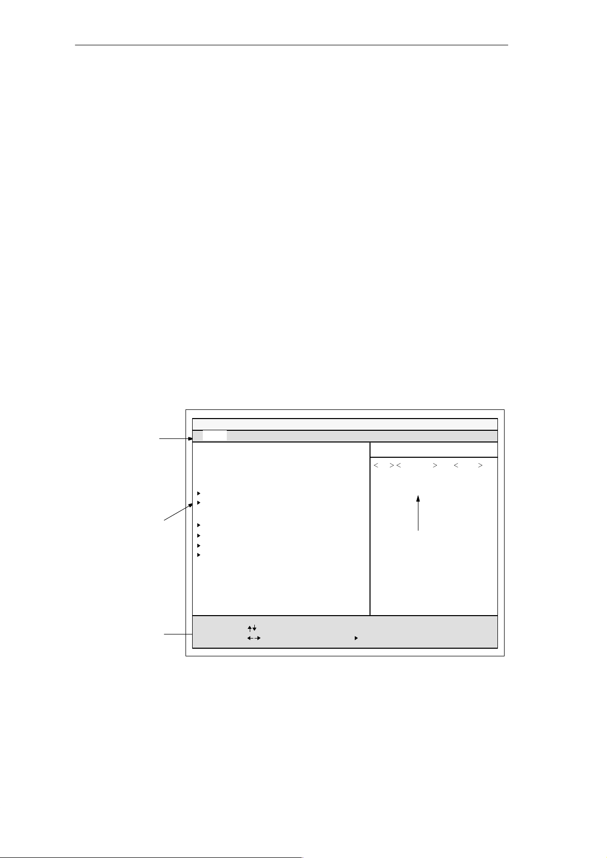
Configuring the PG 720
Screen Display
Following
Power On
With the standard setting of your programming device, the display shown
below appears following power-on:
Phoenix NoteBIOS 4.0
Copyright 1985-95 Phoenix Technologies Ltd., All Rights
Reserved.
SIEMENS PG 720 P
CPU = xxx*) 233 MHz**) Mobile
0000640K System RAM Passed
0031744K Extended RAM Passed
UMB upper limit segment address: F2xx
Fixed Disk 0: IBM DMCA 21440
Press <F2> to enter SETUP
If you press the F2 key while the above display is shown, you select the
ROM-based BIOS setup program. In this program, you can set a number of
system functions and hardware configurations of your programming device.
The standard settings are effective on delivery. You can change these settings
using the BIOS setup. The modified settings become effective when you have
saved them and terminated the BIOS setup.
The following screen form appears when you start the BIOS setup:
Menu bar
Selectable
submenu
Operating keys
*) CPU–Typ
**) MHz (133 or 233 MHz)
PhoenixBIOS Note BIOS 4.0 Setup-Copyright 1985-95 Phoenix Technologies Ltd.
Main
System Time:
System Date:
Diskette A: [ 1.44 MB, 31/2” ]
Diskette B: Not installed
IDE Adapter 0 Master (C: 1445 MB)
IDE Adapter 0 Slave (None)
Video System: EGA/VGA
Memory Cache:
Boot Sequence: [ A: then C: ]
Numlock: [ Off ]
Hardware Options
System Memory:
Extended Memory:
F1
Help
ESC
Exit
Security Power Savings ExitAdvanced
Select Item
Select Menu
[ 15:55:32 ]
[ 03/01/1997 ]
640 KB
31744 kB
– / +
Enter Select
Change Values
Sub-MenuF9F10
Item Specific Help
,
Shift-Tab Enter, or
Tab
selects field.
Help window
Figure 6-1 Main SETUP Menu
Setup Defaults
Previous Values
PG 720 P Programming Device
C79000-G7076-C721-02
6-3
Page 68
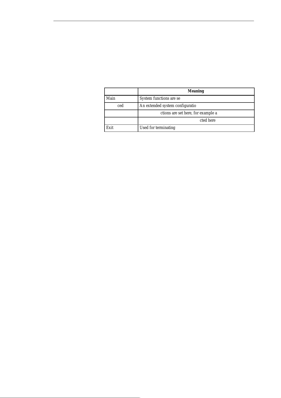
БББББББББББББББББ
БББББББББББББББББ
БББББББББББББББББ
БББББББББББББББББ
БББББББББББББББББ
БББББББББББББББББ
Configuring the PG 720
Menu Structure
The screen is divided into four sections. In the top section, you can select the
menu screens [Main], [Advanced], [Security], [Power Savings], [Exit]. In the
left of the center section you can select various settings or submenus. Brief
help texts appear on the right for the currently selected menu entry. The
bottom section contains information for operator inputs.
You can move between the menu screens using the cursor keys [←] and [→].
Menu
Main
Advanced
Security
Power Savings
Exit
System functions are set here
An extended system configuration can be set here
Security functions are set here, for example a password
Power-saving functions can be selected here
Used for terminating and saving
Meaning
6-4
PG 720 P Programming Device
C79000-G7076-C721-02
Page 69
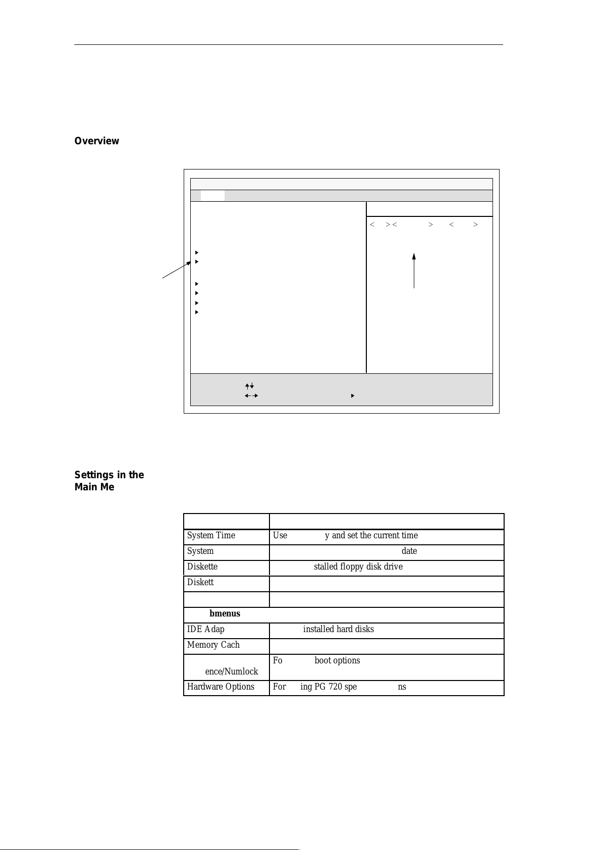
6.1.1 The Main Menu
Configuring the PG 720
Overview
Selectable
submenu
The Main menu is structured as follows:
PhoenixBIOS Note BIOS 4.0 Setup-Copyright 1985-95 Phoenix Technologies Ltd.
Main
System Time:
System Date:
Diskette A: [ 1.44 MB, 31/2” ]
Diskette B: None
IDE Adapter 0 Master (C: 1445 MB)
IDE Adapter 0 Slave (None)
Video System: EGA/VGA
Memory Cache:
Boot Sequence: [ A: then C: ]
Numlock: [ On ]
Hardware Options
System Memory:
Extended Memory:
F1
Help
ESC
Exit
Figure 6-2 Main SETUP Menu
Security Power Savings ExitAdvanced
Select Item
Select Menu
[ 15:55:32 ]
[ 03/01/1997 ]
640 KB
31744 kB
– / +
Enter Select
Change Values
Sub-MenuF9F10
Item Specific Help
,
Tab
Shift-Tab Enter, or
selects field.
Help window
Setup Defaults
Previous Values
Settings in the
Main Menu
PG 720 P Programming Device
C79000-G7076-C721-02
In the Main menu, you can move upwards and downwards using the cursor
keys [↑] and [↓] to select the following system parameters:
Menu Item Function
System Time
System Date
Diskette A
Diskette B
Video System
via submenus
IDE Adapter
Memory Cache
Boot
Sequence/Numlock
Hardware Options
Used to display and set the current time
Used to display and set the current date
Name of installed floppy disk drive
None
Display setting
Type of installed hard disks
For setting memory options
For setting boot options
For setting PG 720 special functions
6-5
Page 70
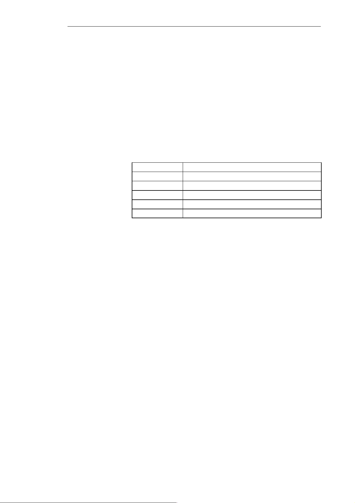
Configuring the PG 720
System Time and
System Date
Diskette A / B
System Time and System Date indicate the current values. Once you have
selected the appropriate option, you can use the [+] and [–] keys to modify
the time setting
Hour:Minute:Second
and the date
Month/Day/Year.
You can move between the entries in the date and time options (for example,
from hour to minute) using the tabulator key.
The name of the installed floppy disk drive in the programming device is set
here. The following entries are possible:
[Not Installed] If a floppy disk drive is not fitted
[360 KB, 5 1/4”]
[1.2 MB, 5 1/4”]
[720 KB, 3 1/2”]
[1.44 MB, 3 1/2”] Standard setting for installed disk drive A
[2.88 MB, 3 1/2”]
6-6
PG 720 P Programming Device
C79000-G7076-C721-02
Page 71
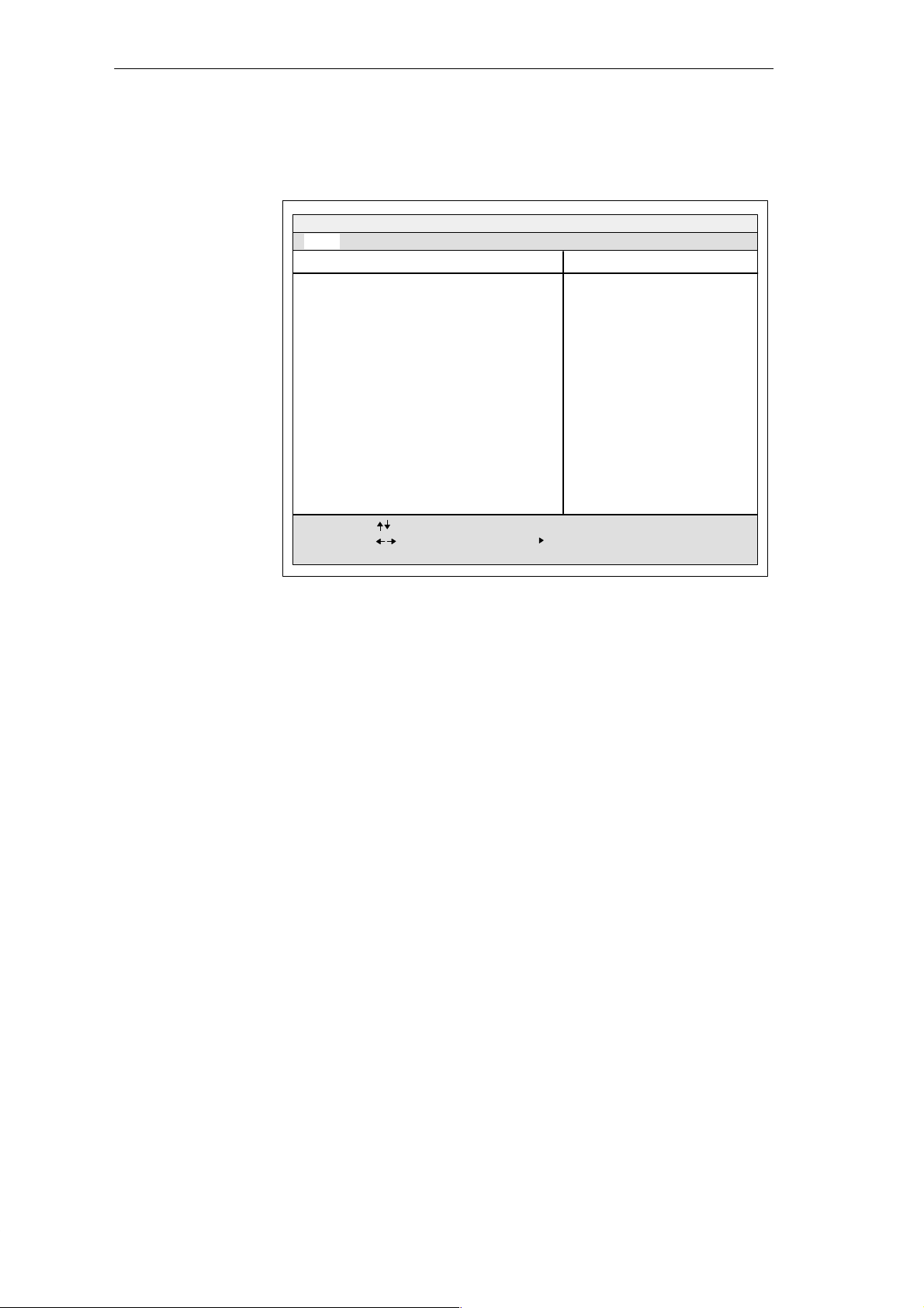
Configuring the PG 720
IDE Adapter
Hard Disk Drive
A branch is made to the following submenu when you select this type of
menu option:
PhoenixBIOS Note BIOS 4.0 Setup-Copyright 1985-95 Phoenix Technologies Ltd.
Main
IDE Adapter 0 Master (C: 1445 Mb)
Autotype Fixed Disk
Type:
Cylinders:
Heads:
Sectors/Track:
Write Precomp:
Multi-Sector Transfers:
LBA Mode Control:
32 Bit I/O:
Transfer Mode:
F1
Help
ESC
Exit
Security Power Savings ExitAdvanced
Select Item
Select Menu
[Press Enter]
[Auto]
1445 MB
[ 2800]
[ 16]
[ 63]
[None]
[16 Sectors]
[Enabled]
[Enabled]
[Fast PIO 4]
– / +
Change Values F9
Enter Select
Item Specific Help
Attempts to automatically detect
the drive type for drives that
comply with ANSI specifications
Setup Defaults
F10
Sub-Menu
Previous Values
“Autotype Hard
Disk” Field
Figure 6-3 “Hard Disk Drive IDE Adapter” Submenu
The parameters which you can select here are usually saved on the respective
IDE drive, and are read from the drive and entered on the screen when you
select the option “Autotype Hard Disk”.
CD-ROM drives with an IDE interface (ATAPI) are not entered here.
The standard parameter “AUTO” is entered in this field. This enables the device
to recognize the hard disk parameters automatically. If you select the “Autotype
Hard Disk” field for a hard disk which does not exist, an abort is executed after
a maximum of five minutes as a result of a timeout, and the existing entries
remain unchanged. It is therefore only meaningful to carry out an autotype for
hard disks present in the system.
In the standard configuration of your programming device, only one hard
disk is entered as the master at IDE adapter 0.
In certain circumstances, it may be necessary to deviate from the proposed
hard disk parameters. In this case, select the corresponding menu option and
then the desired value using the [+] and [–] keys. Enter “none” in the “T ype”
field if an IDE hard disk or an IDE CD-ROM is not connected, or a number
from 1 to 39 if a predefined type of hard disk is to be used.
Select “User” if you wish to define your own type of hard disk; you must
then additionally enter the hard disk parameters in the fields “Cylinders”,
“Heads”, “Sectors/Track”, “Write Precomp”.
PG 720 P Programming Device
C79000-G7076-C721-02
6-7
Page 72

Configuring the PG 720
“Multi-Sector
Transfers” Field
“LBA Mode Control”
Field
“32 Bit-I/O” Field
“Transfer Mode”
Field
The number of sectors which are transmitted per interrupt are transferred in the
“Multi-Sector Transfers” field. The value depends on the drive and should only
be set using the autotype function.
Disabled 1 sector
2,4,6,8,16 Sectors
“Enabled” in the “LBA Mode Control” field (enabled, disabled) means that hard
disk capacities greater than 528 MB are supported. The value depends on the
drive and should only be set using the autotype function.
The type of access to the drive is defined in the option ”32 Bit I/O”:
Disabled 16-bit access
Enabled 32-bit access
The transmission rate to the IDE drive is set in the “Transfer Mode” field. The
value depends on the drive and should only be set using the autotype function.
The following settings are possible:
Standard, Fast PIO1, Fast PIO2, Fast PIO3, Fast PIO4.
You should never set a higher Fast PIO mode than that set by the autotype
function.
We recommend that you use the autotype function.
With specific operating systems, such as SCO OOT3.0, SORIX, etc., you may
have to set the “LBA Mode” to “disabled”.
Exit the submenu using the ESC key.
6-8
PG 720 P Programming Device
C79000-G7076-C721-02
Page 73
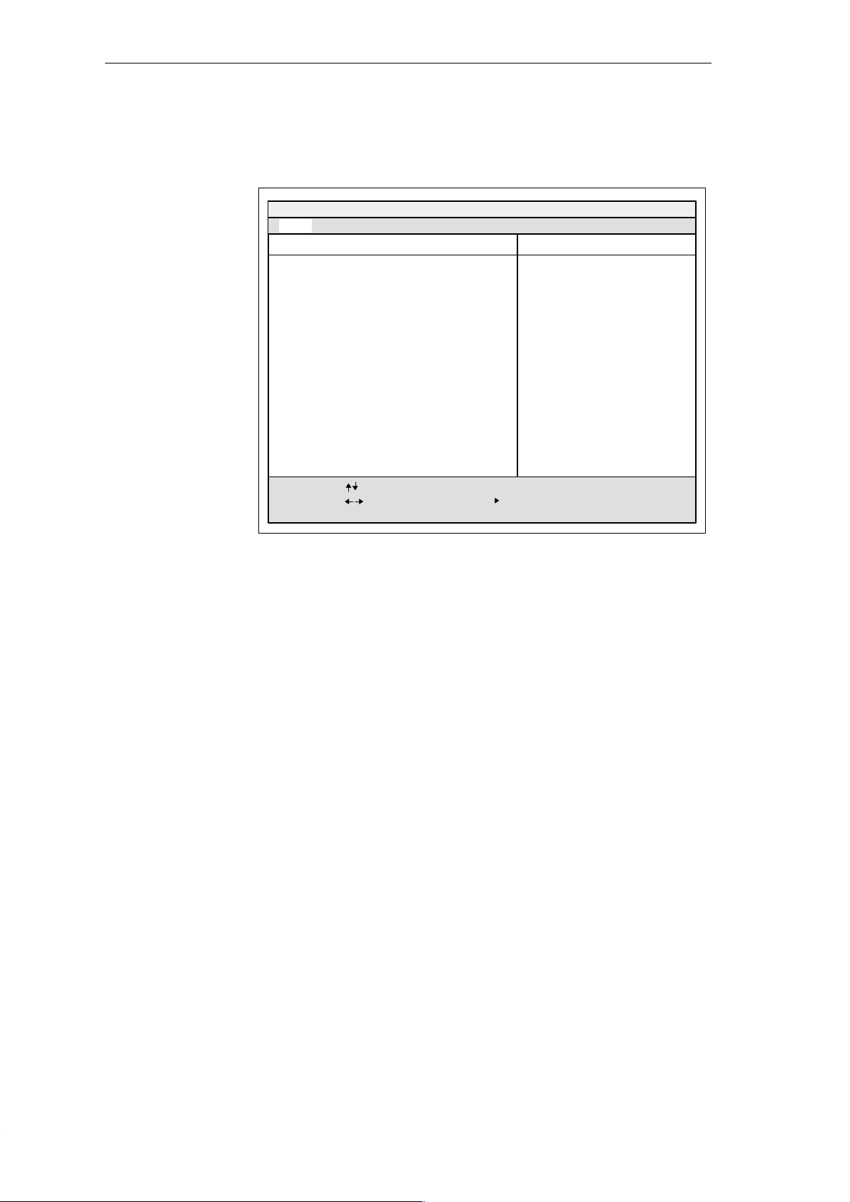
Configuring the PG 720
“Memory Cache”
Field
The following submenu appears when you select the “Memory Cache” field
in the main menu:
PhoenixBIOS Note BIOS 4.0 Setup-Copyright 1985-95 Phoenix Technologies Ltd.
Main
Cache System BIOS:
Cache Video BIOS:
F1
Help
ESC
Exit
Security Power Savings ExitAdvanced
Memory Cache
Select Item
Select Menu
[Enabled]
[Enabled]
– / +
Change Values F9
Enter Select
Item Specific Help
Controls Caching of System Bios,
which may improve the
performance of your
applications.
Setup Defaults
F10
Sub-Menu
Previous Values
Figure 6-4 “Memory Cache” Submenu
A cache is a fast intermediate memory located in the CPU. Repeated memory
access operations can be carried out more quickly via the fast cache,
provided the feature is enabled. It may be necessary to disable the cache
when using certain hardware or software, because intentional program run
times or delay times are prevented by the fast cache.
PG 720 P Programming Device
C79000-G7076-C721-02
6-9
Page 74
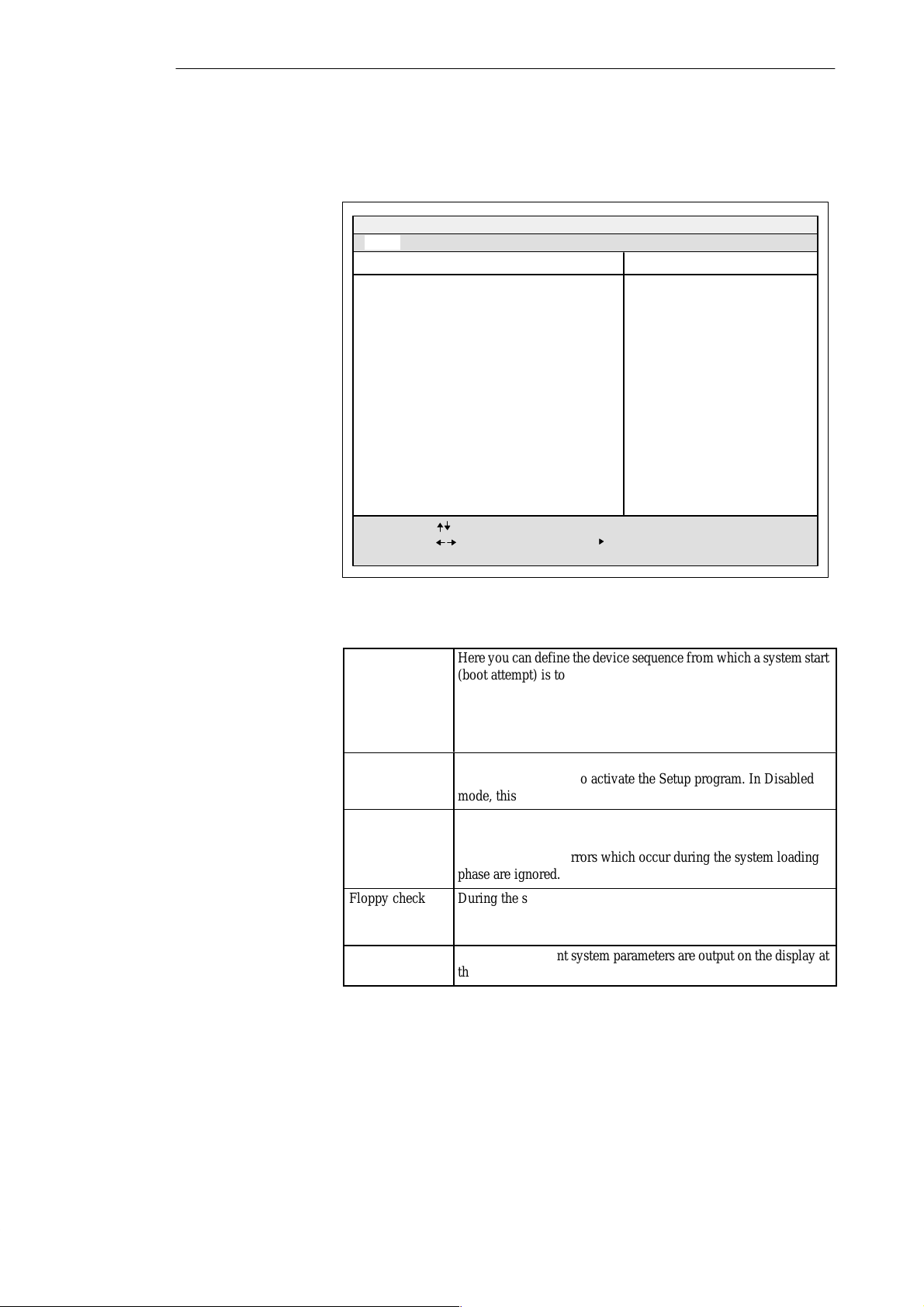
БББББББББББББББББ
Á
Á
Á
Á
БББББББББББББББББ
Á
Á
БББББББББББББББББ
Á
Á
Á
Á
БББББББББББББББББ
Á
Á
БББББББББББББББББ
Á
Á
Configuring the PG 720
“Boot Sequence”
Field
The following submenu appears when you select the “Boot Sequence” field
in the main menu:
PhoenixBIOS Note BIOS 4.0 Setup-Copyright 1985-95 Phoenix Technologies Ltd.
Main
Boot sequence:
SETUP prompt: [Enabled]
POST errors: [Enabled]
Floppy check: [Enabled]
Summary screen: [Enabled]
F1
Help
ESC
Exit
Security Power Savings ExitAdvanced
Boot Options
[A: then C:]
Select Item
Select Menu
– / +
Change Values F9
Enter Select
Sub-Menu
Item Specific Help
Order system searches drives
for a boot disk.
Setup Defaults
F10
Previous Values
Figure 6-5 “Boot Options” Submenu
Boot sequence
SETUP prompt
Here you can define the device sequence from which a system start
(boot attempt) is to be carried out first.
БББББББББББББББ
A: then C: First from floppy A: then from drive C:
БББББББББББББББ
C: then A: First from drive C: then from floppy A:
БББББББББББББББ
C: only Only from drive C:
During the system loading phase, a message at the bottom of the
screen tells you how to activate the Setup program. In Disabled
БББББББББББББББ
mode, this message is not displayed.
POST Errors
Floppy check
Summary screen
The loading procedure is aborted if an error is detected during the
БББББББББББББББ
system loading phase and an error message appears.
БББББББББББББББ
In Disabled mode, errors which occur during the system loading
phase are ignored.
БББББББББББББББ
During the system loading phase, the floppy head is moved by a
number of steppings to the inside, and then back again. This test is
БББББББББББББББ
useful because the drive is initialized again in the process.
The most important system parameters are output on the display at
the end of the system loading phase.
БББББББББББББББ
6-10
PG 720 P Programming Device
C79000-G7076-C721-02
Page 75
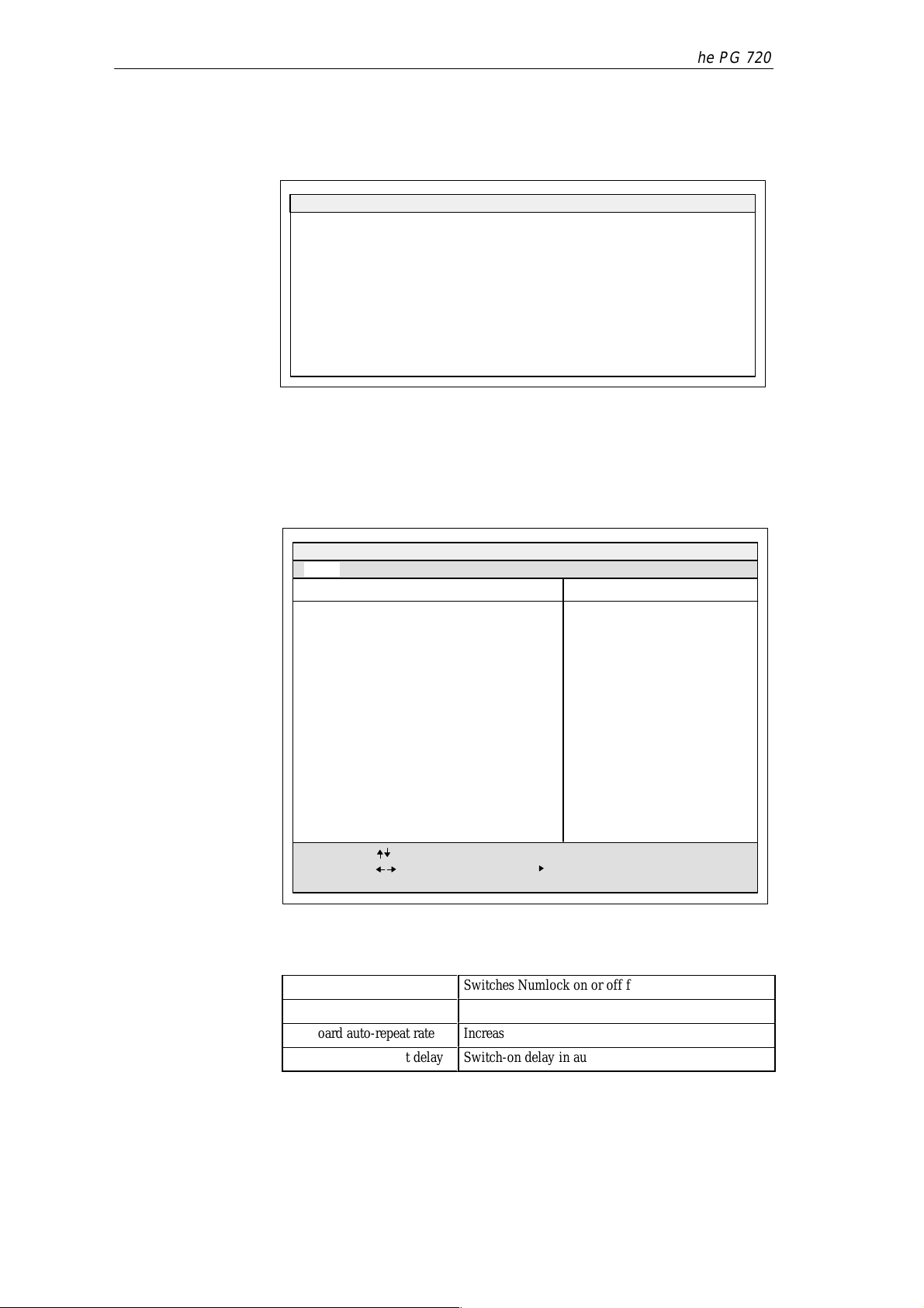
Example of a summary screen:
PhoenixBIOS 1985-95 Phoenix Technologies Ltd.
CPU [xxx
*)MHz]:
Coprocessor: Installed
System RAM: 640 KB
Extended RAM: 31744 KB
Shadow RAM: 384 KB
Cache RAM: None
Configuring the PG 720
System ROM:
BIOS Date: 03/06/97
COM Ports: 03F8, 02F8
LPT Ports: 0378
Display Type: EGA / VGA
PS/2 Mouse: Installed
F2xx – FFFF
“Numlock” Field
Hard Disk 0: 1445 MB
Hard Disk 1: None
Diskette A: 1.44 MB, 31/2 ”
Diskette B: None
*) CPU-T yp
The following submenu appears if you select the “Numlock” field in the
main menu:
PhoenixBIOS Note BIOS 4.0 Setup-Copyright 1985-95 Phoenix Technologies Ltd.
Main
Numlock:
Key Click: [Disabled]
Keyboard auto-repeat rate: [30/s]
Keyboard auto-repeat delay: [1/2 s]
Security Power Savings ExitAdvanced
Keyboard Features
[On]
Item Specific Help
Selects Power-on state for
Numlock
*) 133 or 233 MHz
PG 720 P Programming Device
C79000-G7076-C721-02
F1
ESC
Help
Exit
Select Item
Select Menu
– / +
Change Values F9
Enter Select
Figure 6-6 “Keyboard Features” Submenu
Numlock
Key Click
Keyboard auto-repeat rate
Keyboard auto-repeat delay
Switches Numlock on or off following power on
A keystroke can be heard
Increase in automatic key repeat rate
Switch-on delay in automatic key repeat
Sub-Menu
Setup Defaults
F10
Previous Values
1
6-11
Page 76
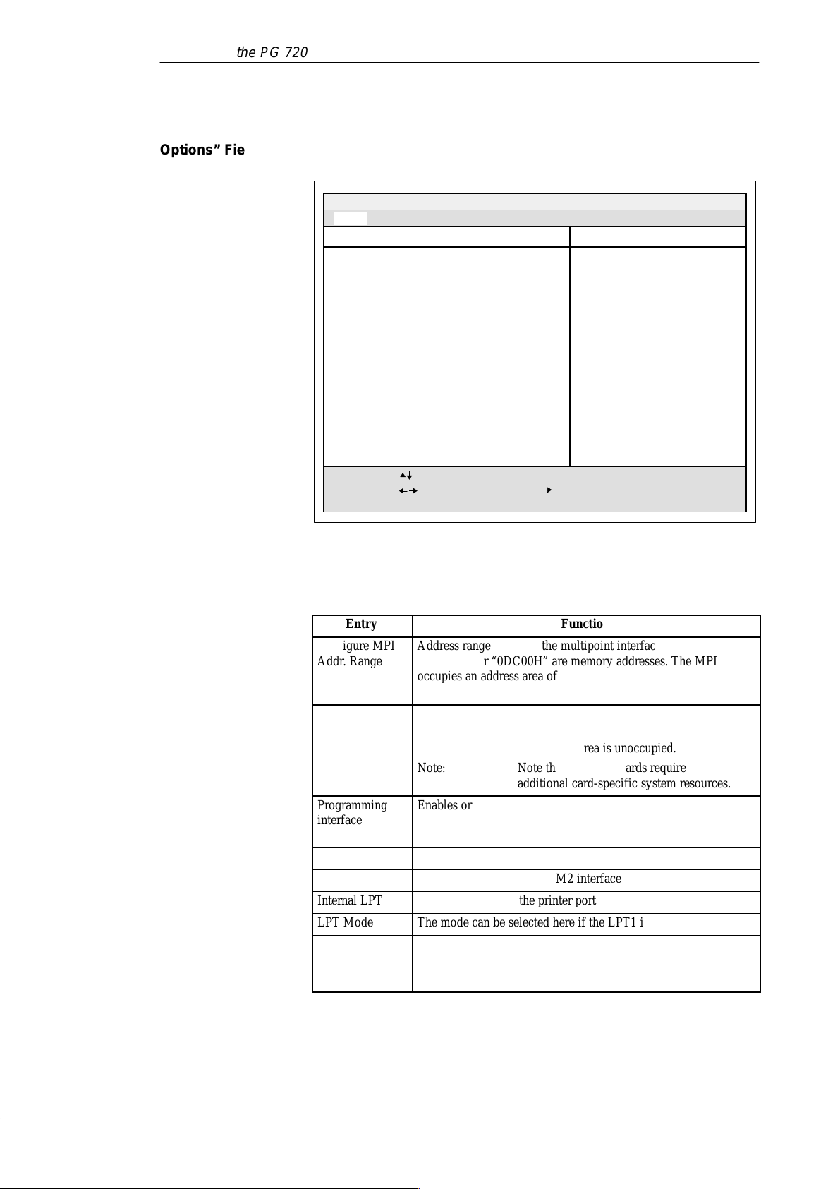
БББББББББББББББББ
Á
Á
БББББББББББББББББ
Á
Á
Á
Á
Á
Á
БББББББББББББББББ
Á
Á
Á
Á
Á
Á
БББББББББББББББББ
Á
Á
Á
БББББББББББББББББ
БББББББББББББББББ
БББББББББББББББББ
БББББББББББББББББ
Á
БББББББББББББББББ
Á
Á
Configuring the PG 720
“Hardware
Options” Field
The following submenu appears when you select the “Hardware Options”
field in the main menu:
PhoenixBIOS Note BIOS 4.0 Setup-Copyright 1985-95 Phoenix Technologies Ltd.
Main
Configure MPI Addr. Range:
PCMCIA Slot: [Enabled]
Programming interface:
Internal COM1:
Internal COM2: [2F8, IRQ 3]
Internal LPT1:
LPT Mode: [Output Only]
CRT / LCD selection:
CRT 640 x 480: [75 Hz]
CRT 800 x 600:
CRT 1024 x 768: [75 Hz]
LCD-Screensize: [Expanded]
Trackball / PS/2 Mouse: [internal]
F1
Help
ESC
Exit
Security Power Savings ExitAdvanced
Hardware Options
[Adr. – CC00H]
[Enabled]
[3F8, IRQ 4]
[378, IRQ 7]
[SIMULTAN]
[75 Hz]
Select Item
Select Menu
– / +
Change Values F9
Enter Select
Sub-Menu
Item Specific Help
Configures the address range
or disables MPI. T o prevent
address conflicts, choose
between two different base
addresses.
Setup Defaults
F10
Previous Values
Figure 6-7 “PG 740 Hardware Options” Submenu
The parameters of the interfaces present on the basic module are set here.
Entry
Configure MPI
Addr. Range
ÁÁÁÁ
ÁÁÁÁ
PCMCIA Slot
ÁÁÁÁ
ÁÁÁÁ
ÁÁÁÁ
Programming
ÁÁÁÁ
interface
ÁÁÁÁ
Internal COM1
Internal COM2
Internal LPT1
LPT Mode
ÁÁÁÁ
Address range in which the multipoint interface is selected.
“0CC00H” or “0DC00H” are memory addresses. The MPI
БББББББББББББББ
occupies an address area of 2 KB. “Disabled” enables the address
БББББББББББББББ
area and disables the interface.
Enables or disables the PCMCIA interface. PCMCIA occupies the
I/O address range 3E0H - 3E1H.
БББББББББББББББ
If the interface is disabled, this area is unoccupied.
БББББББББББББББ
Note: Note that PCMCIA cards require
БББББББББББББББ
additional card-specific system resources.
Enables or disables the S5 module interface and the interface for
БББББББББББББББ
S7 memory cards. This interface occupies the I/O address range
300H - 31FH.
БББББББББББББББ
Enables or disables the COM1/TTY interface
Enables or disables the COM2 interface
Enables or disables the printer port
The mode can be selected here if the LPT1 interface is enabled.
Output Only Standard mode
Bi-directional Printer port can also be used as an input port or
БББББББББББББББ
EPP mode for EPP support
Function
6-12
PG 720 P Programming Device
C79000-G7076-C721-02
Page 77
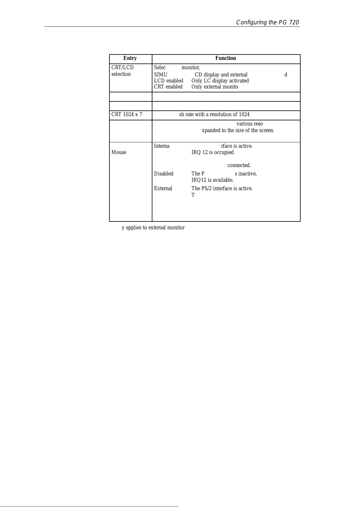
Á
Á
Á
Á
Á
Á
Á
Á
Á
Á
Á
Á
Á
Á
Á
Á
Á
Á
Á
Á
Á
Á
Configuring the PG 720
Entry
CRT/LCD
ÁÁÁÁ
selection
ÁÁÁÁ
Selection of monitor,
БББББББББББББББ
SIMULTAN LCD display and external monitor activated
LCD enabled Only LC display activated
БББББББББББББББ
CRT enabled Only external monitor activated
CRT 640 x 480
CRT 800 x 600
CRT 1024 x 768
LCD Screen Size
ÁÁÁÁ
ÁÁÁÁ
Trackball / PS/2
Mouse
ÁÁÁÁ
ÁÁÁÁ
ÁÁÁÁ
ÁÁÁÁ
ÁÁÁÁ
ÁÁÁÁ
ÁÁÁÁ
Image refresh rate with a resolution of 640 x 480 pixels
Image refresh rate with a resolution of 800 x 600 pixels
Image refresh rate with a resolution of 1024 x 768 pixels
EXPANDED: With an LC display, various resolutions
БББББББББББББББ
БББББББББББББББ
Normal: No expansion to 800 x 600 is made
Internal The PS/2 interface is active.
БББББББББББББББ
БББББББББББББББ
Disabled The PS/2 interface is inactive,
БББББББББББББББ
БББББББББББББББ
External The PS/2 interface is active.
БББББББББББББББ
БББББББББББББББ
Changes do not become active until the device is switched on
БББББББББББББББ
again.
* Only applies to external monitor
Function
are expanded to the size of the screen.
IRQ 12 is occupied.
In this mode, a keyboard with integrated
trackball can be connected.
IRQ12 is available.
The IRQ 12 is occupied.
The keyboard trackball is disabled.
PG 720 P Programming Device
C79000-G7076-C721-02
6-13
Page 78
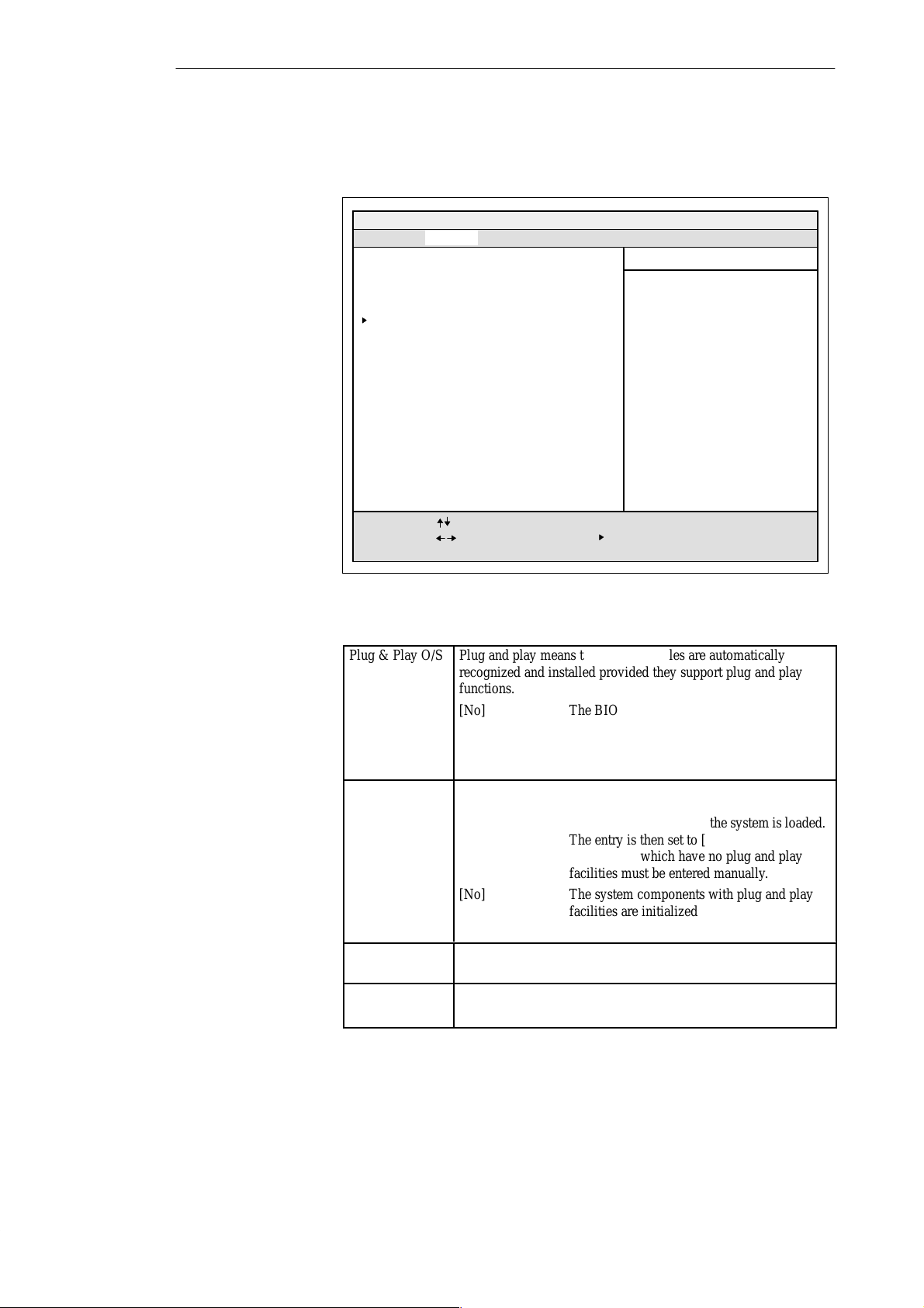
Á
Á
Á
Á
БББББББББББББББББ
Á
Á
Á
Á
Á
Á
Á
Á
Á
Á
Á
БББББББББББББББББ
Á
Á
Á
Á
Á
Á
Á
Á
БББББББББББББББББ
Á
Á
Á
БББББББББББББББББ
Á
Á
Configuring the PG 720
6.1.2 The Advanced Menu
Menu Structure
Settings in the
Advanced Menu
PhoenixBIOS Note BIOS 4.0 Setup-Copyright 1985-95 Phoenix Technologies Ltd.
Main
Security Power Savings ExitAdvanced
Item Specific Help
Warning!
Setting items on this menu to incorrect values
may cause your system to malfunction.
PCI Devices
Plug & Play O/S [No]
Reset Configuration Data [No]
Diskette Controller: [Enabled]
Local Bus IDE Adapter:
[Enabled]
VGA Interrupt: [Enabled]
Large Disk Access Mode:
F1
ESC
Help
Exit
Select Item
Select Menu
[DOS]
– / +
Change Values F9
Enter Select
Sub-Menu
F10
Figure 6-8 “Advanced” Menu
Plug & Play O/S
Plug and play means that fitted modules are automatically
recognized and installed provided they support plug and play
ÁÁÁÁ
ÁÁÁÁ
ÁÁÁÁ
ÁÁÁÁ
Reset
ÁÁÁÁ
Configuration
Data
ÁÁÁÁ
ÁÁÁÁ
ÁÁÁÁ
ÁÁÁÁ
ÁÁÁÁ
Diskette
controller
ÁÁÁÁ
Local Bus IDE
adapter
ÁÁÁÁ
БББББББББББББББ
functions.
[No] The BIOS handles the complete plug and play
БББББББББББББББ
БББББББББББББББ
[Yes] The operating system handles some of the
БББББББББББББББ
facilities
plug and play functions
[Yes] All previous installations under plug and
БББББББББББББББ
БББББББББББББББ
БББББББББББББББ
БББББББББББББББ
[No] The system components with plug and play
БББББББББББББББ
БББББББББББББББ
play are deleted, and the configuration is
retriggered the next time the system is loaded.
The entry is then set to [No]. System
components which have no plug and play
facilities must be entered manually.
facilities are initialized the next time the
system is loaded.
Enables or disables the floppy controller of the basic module.
БББББББББББББББ
[Enabled] One IDE interface for up to two drives.
[Disabled] No local IDE interface
БББББББББББББББ
Setup Defaults
Previous Values
6-14
PG 720 P Programming Device
C79000-G7076-C721-02
Page 79
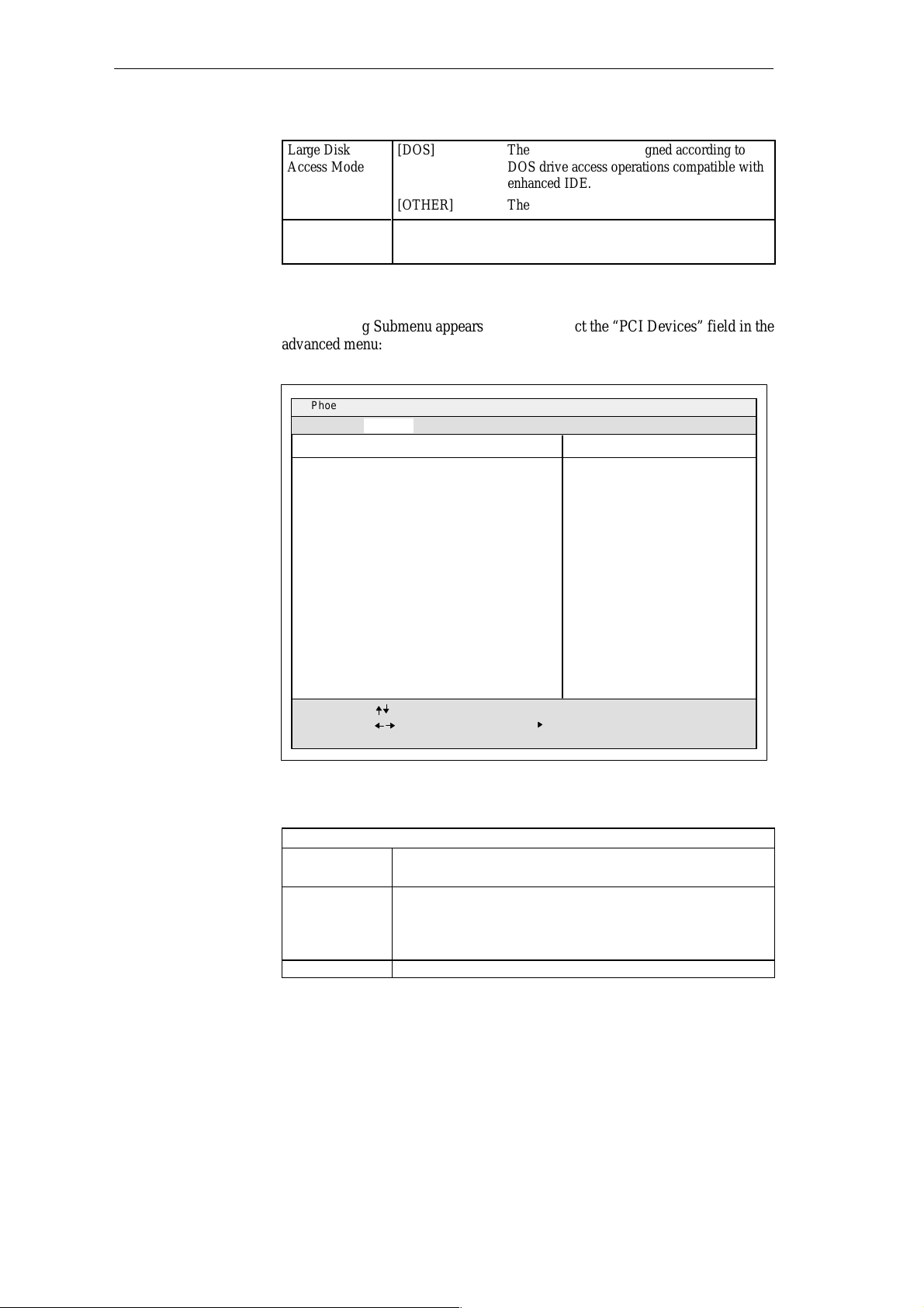
Á
Á
Á
Á
Á
Á
Á
Á
Configuring the PG 720
“PCI Devices”
Field
Large Disk
ÁÁÁÁ
Access Mode
ÁÁÁÁ
ÁÁÁÁ
VGA Interrupt
ÁÁÁÁ
[DOS] The drive tables are designed according to
БББББББББББББББ
БББББББББББББББ
[OTHER] The tables are not adapted.
БББББББББББББББ
DOS drive access operations compatible with
enhanced IDE.
[Enabled] IRQ 9 is reserved for the VGA card.
[Disabled] IRQ 9 is reserved for other devices.
БББББББББББББББ
The following Submenu appears when you select the “PCI Devices” field in the
advanced menu:
PhoenixBIOS Note BIOS 4.0 Setup-Copyright 1985-95 Phoenix Technologies Ltd.
Advanced
PCI Devices
PCI Device, Slot #1:
Enable Master: [Enabled]
Default Latency Timer: [Yes]
Latency Timer: [0040]
Item Specific Help
Enable selected device as
a PCI bus master.
PG 720 P Programming Device
C79000-G7076-C721-02
F1
ESC
Help
Exit
Select Item
Select Menu
– / +
Change Values F9
Enter Select
Sub-Menu
Setup Defaults
F10
Previous Values
Figure 6-9 “PCI Devices” Submenu
PCI Device, Slot#1
Enable Master [Enable] PCI master operation is permitted for this slot.
[Disable] No master operation is permitted for this slot.
Default Latency
Timer
[Yes] PCI master module defines the number of active PCI
clock cycles.
[No] The set Latency Timer value defines the number of
active PCI clock cycles.
Latency Timer [0040] Number of active PCI clock cycles
6-15
Page 80
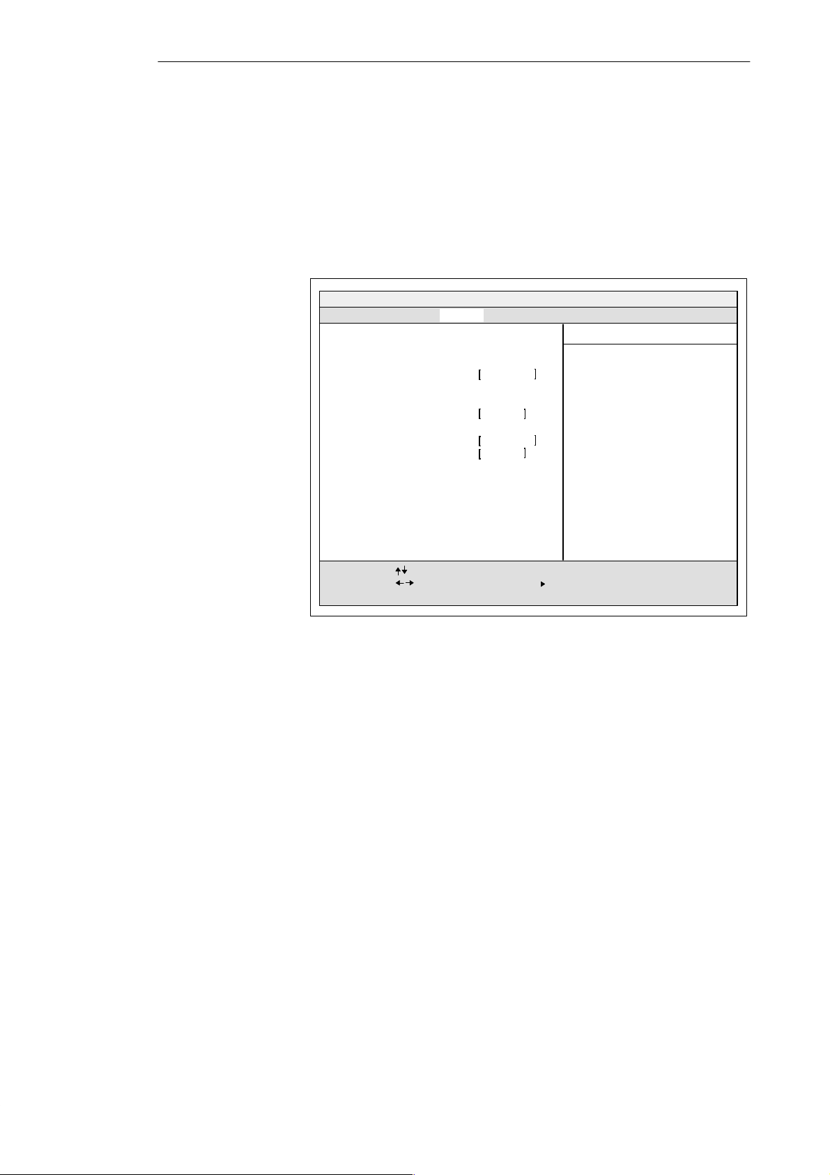
Configuring the PG 720
6.1.3 The Security Menu
Summary
You can only edit the fields enclosed in square brackets. Two passwords are assigned to protect your programming device from unauthorized use. You can use
the supervisor password to prevent use of diskettes for the normal user and to
limit use of the hard disk.
PhoenixBIOS Note BIOS 4.0 Setup-Copyright 1985–95 Phoenix Technologies Ltd.
Main
Supervisor Password is Disabled
User Password is Disabled
Set Supervisor Password
Set User Password Press Enter
Password on boot:
Diskette access:
Fixed disk boot sector:
F1
Help
ESC
Exit
Security Power Savings ExitAdvanced
Select Item
Select Menu
Press Enter
Disabled
Supervisor
Normal
– / +
Change Values F9
Enter Select
Sub-Menu
Item Specific Help
Setup Defaults
F10
Previous Values
6-16
Figure 6-10 “Security” Submenu
PG 720 P Programming Device
C79000-G7076-C721-02
Page 81
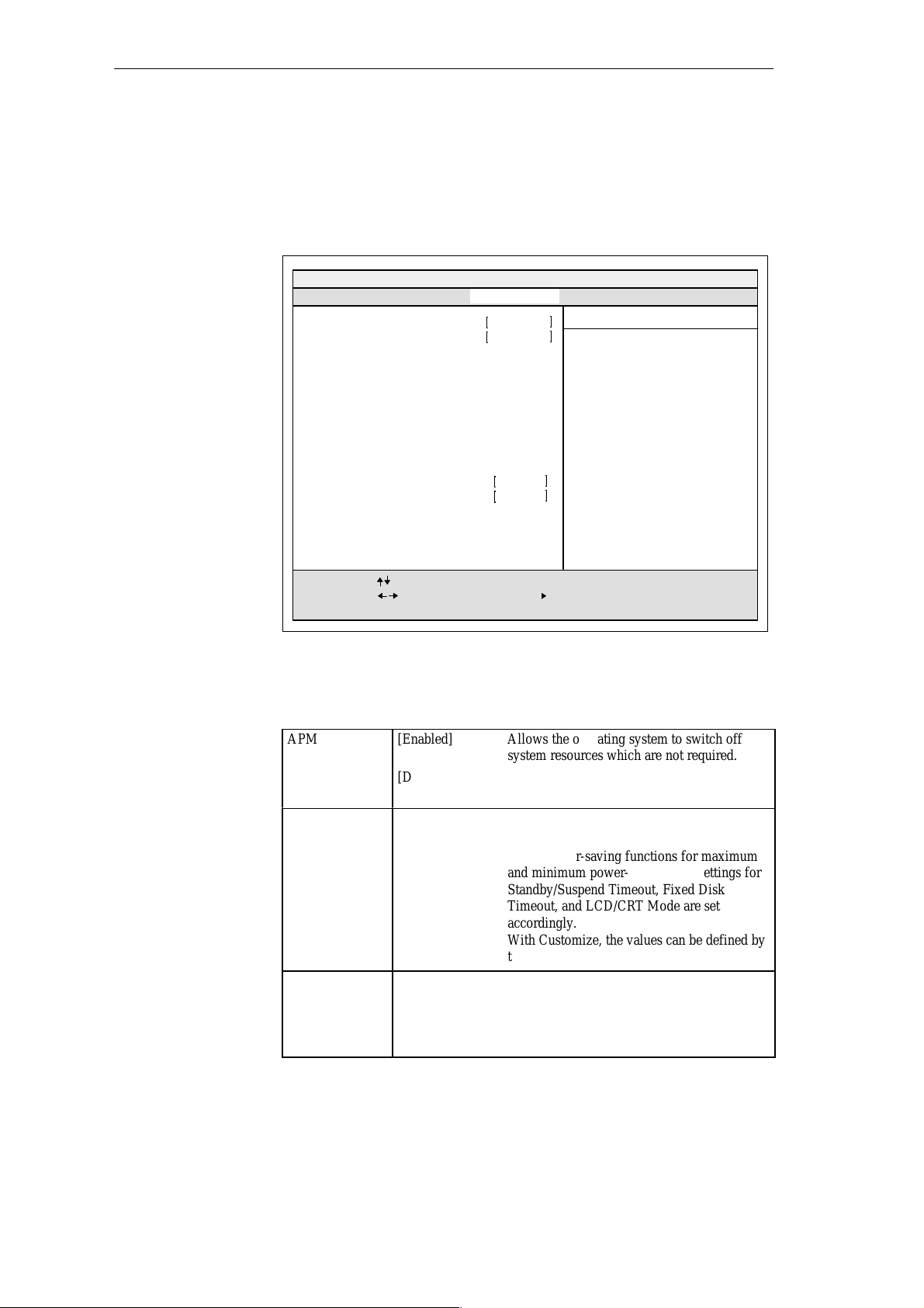
6.1.4 The Power Savings Menu
Á
Á
Á
Á
Á
Á
Á
Á
Á
Á
Á
Á
Á
Á
Á
Á
Configuring the PG 720
Summary
This menu has the following structure:
PhoenixBIOS Note BIOS 4.0 Setup-Copyright 1985-95 Phoenix Technologies Ltd.
Main
Advanced
APM: Enabled
Power Savings:
Idle Mode: Disabled
Standby Timeout: Disabled
Suspend Timeout: Disabled
Fixed Disk Timeout: Disabled
LCD/CRT Standby-Mode: Suspend off
Additional Powersaving Options
Backlight: Full on
F1
Help
ESC
Exit
Figure 6-11 “Power Savings” Submenu
Security Power-Savings Exit
Disabled
DisabledResume on Modem Ring:
Select Item
Select Menu
– / +
Change Values F9
Enter Select
Item Specific Help
APM (Advanced Power Management)
allows APM aware software to better
manage power savings.
Sub-Menu
F10
Setup Defaults
Previous Values
Various power saving modes can be set using the Power Savings menu:
APM
ÁÁÁÁ
ÁÁÁÁ
Power Savings
ÁÁÁÁ
ÁÁÁÁ
ÁÁÁÁ
ÁÁÁÁ
ÁÁÁÁ
ÁÁÁÁ
Idle Mode *) [Disable] No power-saving function while CPU is
[Enabled] Allows the operating system to switch off
БББББББББББББББ
[Disabled] The operating system cannot use APM
БББББББББББББББ
[Maximum Performance], [Disable], [Maximum Battery Life],
БББББББББББББББ
[Customize]
БББББББББББББББ
БББББББББББББББ
БББББББББББББББ
БББББББББББББББ
БББББББББББББББ
system resources which are not required.
(advanced power management) access.
Preset power-saving functions for maximum
and minimum power-saving. The settings for
Standby/Suspend Timeout, Fixed Disk
Timeout, and LCD/CRT Mode are set
accordingly.
With Customize, the values can be defined by
the user.
inactive.
[Enable] After 2 seconds, the CPU clock frequency is
reduced.
This lowers the power required.
PG 720 P Programming Device
C79000-G7076-C721-02
6-17
Page 82
Á
Á
Á
БББББББББББББББББ
Á
Á
Á
Á
Á
Á
Á
БББББББББББББББББ
Á
Á
Á
Á
Configuring the PG 720
Standby Timeout
ÁÁÁÁ
ÁÁÁÁ
ÁÁÁÁ
Suspend
Timeout
ÁÁÁÁ
ÁÁÁÁ
ÁÁÁÁ
БББББББББББББББ
[1, 2, 4, 6, the programming device goes to standby mode
БББББББББББББББ
8, 12, 16] if no mouse or keyboard operation occurs.
[Disabled] No standby mode.
БББББББББББББББ
[5, 10, 15, 20,
БББББББББББББББ
30, 40, 60] the programming device goes to suspend
БББББББББББББББ
БББББББББББББББ
[Disabled] No suspend mode.
After the set time has expired (minutes),
After the set time has expired (minutes),
mode.
*) The idle mode can cause online functions to be aborted. If you are using
online functions it should therefore be switched to “Disable.”
In suspend mode, the CPU is stopped and can only be restarted by an
interrupt, for example keyboard, mouse, COM 1/2.
Fixed Disk
Timeout
LCD/CRT
Standby Mode
Resume on
Modem Ring
[1min][2min] the hard disk drive is switched off if it
[4min][6min] is not accessed.
[8min][10min] If the hard disk is accessed after it has been
[15min] switched off, an access delay occurs while the
[Disabled] Hard disk runs continuously.
[Standby Off] Monitor and display are switched off when
[Suspend Off] Monitor and display are not switched of f until
[Always On] Monitor or display always remains in
[Disabled] If this function is enabled, the programming
[Enabled] device can be called out of suspend mode by
After the set time has expired (minutes),
hard disk is booted up again.
standby mode is reached.
suspend mode is reached.
operation.
the “RING” signal of a modem.
The relevant additional hardware and software
are required.
6-18
PG 720 P Programming Device
C79000-G7076-C721-02
Page 83
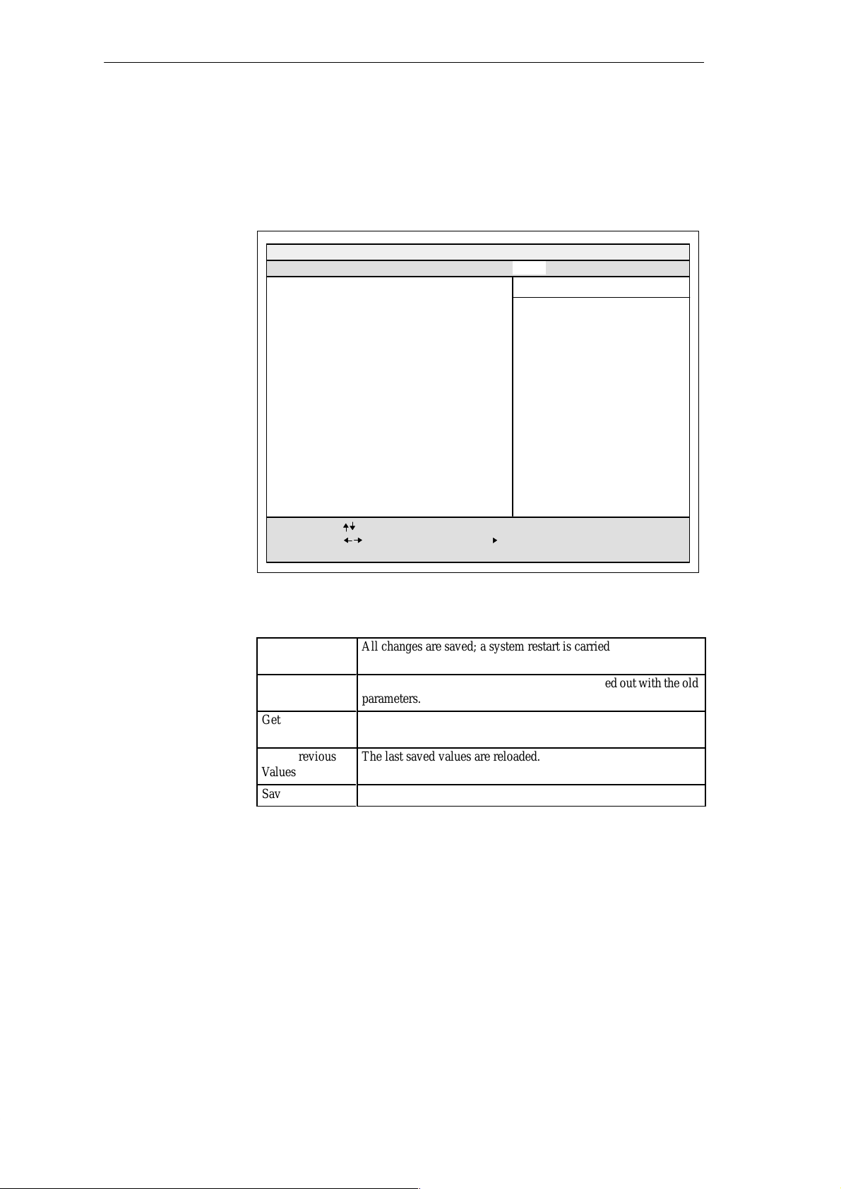
6.1.5 The Exit Menu
Á
Á
Á
Configuring the PG 720
The Exit Menu
The setup program is always terminated using this menu.
PhoenixBIOS Note BIOS 4.0 Setup-Copyright 1985-95 Phoenix Technologies Ltd.
Main
Advanced
Save Changes & Exit
Discard Changes & Exit
Get Default Values
Load Previous Values
Save Changes
F1
Help
ESC
Exit
Figure 6-12 “Exit” Submenu
Security Power Savings Exit
Select Item
Select Menu
– / +
Change Values F9
Enter Select
Item Specific Help
Exit after writing all changed SETUP
item values to CMOS.
Sub-Menu
F10
Setup Defaults
Previous Values
PG 720 P Programming Device
C79000-G7076-C721-02
Save Changes &
Exit
Discard Changes
& Exit
Get Default
Values
Load Previous
Values
Save Changes
All changes are saved; a system restart is carried out with the new
parameters.
БББББББББББББББ
All changes are rejected; a system restart is carried out with the old
parameters.
All parameters are set to safe values. The hard disk must be entered
БББББББББББББББ
explicitly.
The last saved values are reloaded.
БББББББББББББББ
Saves all setup entries.
6-19
Page 84
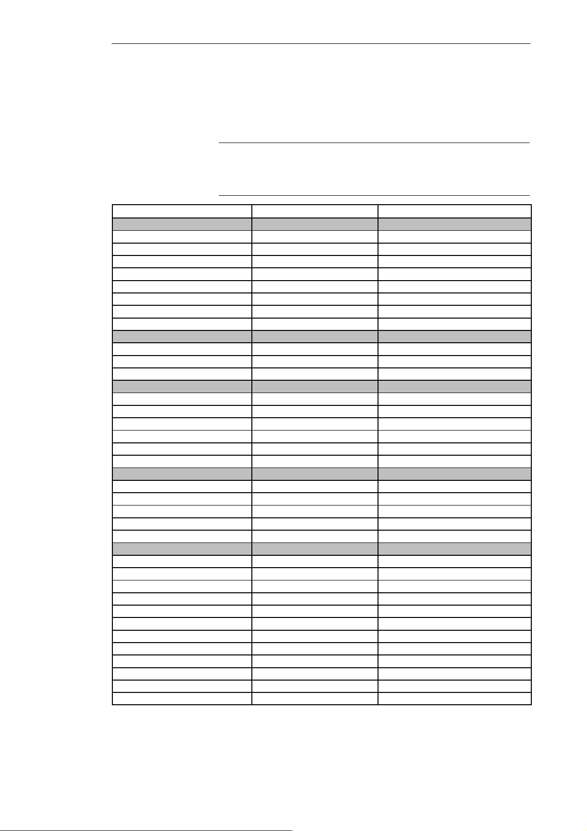
Configuring the PG 720
If you have made any modifications to your standard SETUP settings, you can
Documenting Your
Device
Configuration
enter them in the following table. You can then refer to these entries if you need
to make any hardware modifications later.
Note
Print the following table out and keep the pages in a safe place once you
have filled in your entries.
System Parameter Standard Settings Your Entries
Main
System Time
System Date
Diskette A 1.44 MB, 31/2
IDE Adapter 0 Master C: 1.440 MB
IDE Adapter 0 Slave None
Video System EGA/VGA
Memory Cache
Cache system BIOS area Enabled
Cache video BIOS area Enabled
Boot sequence
Boot sequence A: then C:
SETUP prompt Enabled
POST errors Enabled
Floppy check Enabled
Summary Screen Enabled
Numlock
Numlock Off
Key click Disabled
Keyboard auto-repeat time 30/s
Keyboard auto-repeat delay 1/2s
Hardware Options
Configure MPI address range Address CC00
PCMCIA Slot Enabled
Internal COM1 3F8, IRQ 4
Internal COM2 2F8, IRQ 3
Internal LPT1 378, IRQ 7
LPT Mode Output Only
CRT/LCD selection SIMULTAN
CRT 640 x 480 75
CRT 800 x 600 75
CRT 1024 x 768 75
LCD Screensize Expanded
Trackball / PS2 Mouse External
6-20
PG 720 P Programming Device
C79000-G7076-C721-02
Page 85
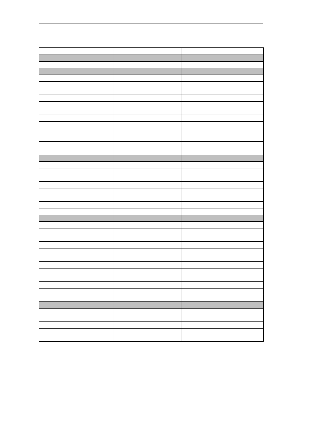
System Parameter Your EntriesStandard Settings
Advanced
PCI Devices
PCI Device, Slot#1
Enable Master Enabled
Default Latency Timer Yes
Latency Timer 0040
Plug & Play O/S No
Reset Configuration Data No
Diskette Controller Enabled
Local Bus IDE Adapter Enabled
VGA Interrupt Enabled
Large Disk Access Mode DOS
Security
Supervisor Password is Disabled
User Password is Disabled
Set Supervisor Password Press Enter
Set User Password
Password on boot Disabled
Diskette Access Supervisor
Fixed disk boot sector Normal
Configuring the PG 720
Power Savings
APM Enabled
Power Savings Disabled
Powersavings by Customize
Idle Mode Disabled
Standby Timeout 4 Minutes
Suspend Timeout 10 Minutes
Fixed Disk Timeout 4 Minutes
LCD/CRT Standby Mode Standby off
Additional Powersaving Options
Backlight Full on
Resume on Modem Ring Disabled
Exit
Save Changes & Edit
Discard Changes & Exit
Get Default Values
Load Previous Values
Save Changes
PG 720 P Programming Device
C79000-G7076-C721-02
6-21
Page 86

Configuring the PG 720
6.2 Configuring the PCMCIA Interface
You can obtain the software you require for using PCMCIA cards under
MS-DOS, such as
Socket Services
Card Services
Client Drivers
Flash File System
from your nearest Siemens sales office or representative.
Your programming device comes supplied with Windows 95 already
installed; this supports the PCMCIA interface.
6-22
PG 720 P Programming Device
C79000-G7076-C721-02
Page 87

Error Diagnostics
7
What Does This
Chapter Contain?
This chapter will help you to locate, identify, and in some cases eliminate
simple errors and faults. The symptoms of the problem, possible causes, and
remedies are listed in the form of a table.
PG 720 P Programming Device
C79000-G7076-C721-02
7-1
Page 88
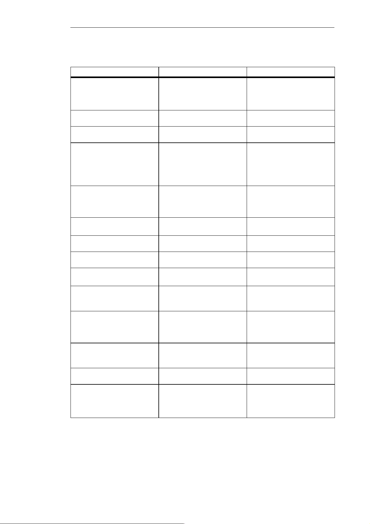
Error Diagnostics
Table 7-1 Errors/Faults in PG 720 Operation
Error/Fault
Power-on LED does not light up PG 720 is switched off
Power supply not properly
connected
Battery run down
Display remains dark after power
up
External monitor remains dark LCD enabled is entered in
Message on the display:
“Invalid configuration
information... Press the F1 key for
continue, F2 to run Setup utility”
Message on the display: “No boot
device available”
Back lighting is not active Wait 3 to 5 seconds until the back
SETUP
Incorrect configuration data Press “F2” key, check the
Diskette in drive A: is not a boot
diskette
Wrong hard disk type entered in
SETUP
Message: “Keyboard stuck key
failure”
Booting of the PG 720 aborted
with a series of beeps
Every time a key is pressed, a beep
is heard and no character appears
Not ready message when
attempting to read a diskette
Read-only error when attempting
to write to a diskette
<\> key does not exist Wrong keyboard driver is being
A key became blocked during the
self-test of the keyboard
Error occurred during the self-test Check hardware
Keyboard buffer overflow <CTRL> <PAUSE>
No diskette inserted
Diskette is not formatted
Diskette is read-only
Read-only hole open on 3.5’’
diskette
used
Cause Remedy
Switch the unit on
Check the power supply, power
cable, and power connector
Charge or replace battery
lighting is active
Enter CRT enabled or
SIMULTAN in SETUP
configuration data in the SETUP
program, if necessary adapt the
default values, and check the
error messages in the first
SETUP menu
Replace diskette with boot
diskette
Use the “Autotype Fixed Disk”
function
Check the keyboard
Restart the system
Insert diskette
Format diskette
Cancel the write protection
German keyboard:
<ALTGr> <ß>
International keyboard
: <\> key
Mouse pointer cannot be moved
with the trackball
The ball is not rotating
No or wrong mouse driver
Clean the trackball and its
housing
Load the correct mouse driver
Mouse pointer moving erratically Trackball dirty Clean the trackball and its
housing
Trackball not working Trackball is switched off
External mouse plugged in
PS/2 interface is set to external or
disabled in Setup
Activate trackball with key
combination F
+ ^
n
Check Setup entry
7-2
PG 720 P Programming Device
C79000-G7076-C721-02
Page 89
Hardware Information
8
What Does This
Chapter Contain?
Chapter
Overview
This chapter contains important reference data about the following:
Hardware addresses
Interrupt assignments
Information about connecting cables
Section Contents Page
8.1 Hardware Address Table 8-2
8.2 Interrupt Assignments 8-6
8.3 PG 720 Video Modes 8-7
8.4 Connector Pinouts 8-8
8.5 Connecting Cables 8-15
PG 720 P Programming Device
C79000-G7076-C721-02
8-1
Page 90
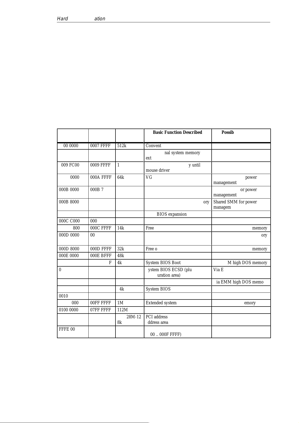
Á
Á
Á
Á
Á
Á
Á
Á
Á
Á
Á
Á
Á
Á
Hardware Information
8.1 Hardware Address Table
There are two kinds of address area:
Memory address area
I/O address area.
Different read/write signals (I/O WR, I/O RD, MEMR, MEMW) are used to
address these areas. The following tables provide you with an overview of
the address areas used. For further information, refer to the description of the
individual function modules.
Table 8-1 Assignment of the Memory Addresses
From
Address
To
Address
Size
0000 0000 0007 FFFF 512k
0008 0000 0009 FBFF 127k
0009 FC00 0009 FFFF 1k
000A 0000 000A FFFF 64k
000B 0000 000B 7FFF 32k
000B 8000 000B FFFF 32k
000C 0000 000C BFFF 48k
000C C000 000C C7FF 2k
000C C800 000C FFFF 14k
000D 0000 000D 7FFF 32k
000D 8000 000D FFFF 32k
000E 0000 000E BFFF 48k
000E C000 000E CFFF 4k
000E D000 000E DFFF 4k
000E E000 000E FFFF 8k
000F 0000 000F FFFF 64k
0010 0000 00EF FFFF 14M
00F0 0000 00FF FFFF 1M
0100 0000 07FF FFFF 112M
0800 0000 FFFD FFFF 4G-128M-12
8k
FFFE 0000 FFFF FFFF 128k
Basic Function Described
ББББББББ
Conventional system memory
Conventional system memory
extended
PS/2 mouse (BIOS) only until
ББББББББ
mouse driver is loaded
VGA graphics refresh memory
ББББББББ
B/W graphics/text refresh memory
VGA graphics/text refresh memory
ББББББББ
VGA BIOS expansion
MPI if enabled
Free or PCMCIA driver
Free or PCMCIA driver
ББББББББ
Free or PCMCIA driver
System BIOS
System BIOS Boot Message Logo
System BIOS ECSD (plug & play
configuration area)
ББББББББ
Setup
System BIOS
Extended system memory
Extended system memory
Extended system memory
PCI address area or shadowed ISA
address area
ББББББББ
System BIOS (shadow of 000E
0000 .. 000F FFFF)
Possible Alternative
БББББББ
Function
Via Setup ISA memory
Via Setup ISA memory
БББББББ
Shared SMM for power
management
БББББББ
Shared SMM for power
management
Shared SMM for power
БББББББ
management
Via EMM high DOS memory
Via EMM high DOS memory
Via EMM high DOS memory
БББББББ
Via EMM high DOS memory
Via EMM high DOS memory
Via EMM high DOS memory
Via EMM high DOS memory
БББББББ
Via EMM high DOS memory
Via Setup ISA memory
БББББББ
8-2
PG 720 P Programming Device
C79000-G7076-C721-02
Page 91
Hardware Information
Table 8-2 I/O Address Assignments
Address Size Description
from to byte Basic Function Possible Alternative Function
0000 000F 16 82C558E ––> DMA 1 Control
Register
(DMA 0, 1, 2, 3)
0010 001F 16 Unoccupied
0020 0021 2 82C558E ––> Interrupt controller 1
Control Register
0022 1 Integrated 82C206 and Chipset
Configuration Index Register
(SYSCFG)
0023 1 82C558E ––> Integrated 82C206
Configuration Data Register
0024 1 Chipset Configuration Data Register
(SYSCFG)
0025 002D 9 Unoccupied
002E 002F 2 Configuration port ultra I/O
0030 003F 16 Unoccupied
0040 0042 3 82C558E ––> Timer Channel 0..2
(Clock,Refresh,Speaker )
0043 1 82C558E ––> Timer Control Register
0044 005F 28 Unoccupied
0060 1 Keyboard controller date
0061 1 82C558E ––> System Control Port B
(Timer,Speaker control,NMI,Parity )
0062 0063 2 Unoccupied
0064 1 Keyboardcontroller CMD / STATUS
0065 006F 11 Unoccupied
0070 1 NMI enable, RTC Index
0071 1 RTC date
0072 0080 15 Unoccupied
0081 0083 3 82C558E ––> DMA Page Register
Ch2,3,1
0084 0086 3 Unoccupied
0087 1 82C558E ––> DMA Page Register
Ch0
0088 1 Unoccupied
0089 008B 3 82C558E ––> DMA Page Register
Ch6,7,5
008C 008E 3 Unoccupied
008F 1 82C558E ––> DMA Page Register
Ch4
0090 0091 2 Unoccupied
0092 1 82C558E ––> System Control Port A
(Fast Reset,Fast A20)
0093 009F 13 Unoccupied
PG 720 P Programming Device
C79000-G7076-C721-02
8-3
Page 92
Hardware Information
Table 8-2 I/O Address Assignments, continued
from Possible Alternative FunctionBasic Functionbyteto
00A0 00A1 2 82C558E ––> Interrupt controller 2
Control Register
00A2 00BF 30 Reserved
00C0 00DF 32 82C558E ––> DMA Controller 2
Control Register (DMA 4, 5, 6, 7)
00E0 1 Configuration register for
MPI,COM,VGA,Progas,Trackball,etc.
00E1 00EF 15 Unoccupied
00F0 00F1 2 Numeric Processor
00F2 00F7 6 Unoccupied
00F8 00FF 8 Numeric Processor
0100 010F 16 Unoccupied
0110 016F 96 Unoccupied
0170 0177 8 Secondary IDE channel (free)
0178 01EF 120 Unoccupied
01F0 01F7 8 Primary on-board IDE channel Can be switched off in Setup; then free
01F8 01FF 8 Unoccupied
0200 020F 16 Unoccupied
0210 0277 104 Unoccupied
0278 027B 4 LPT 2 ( Unoccupied )
027C 02E7 108 Unoccupied
02E8 02EF 8 COM 4 ( Unoccupied )
02F0 02F7 8 Unoccupied
02F8 02FF 8 COM2 ( / IRDA ) Can be switched off in Setup; then free
0300 031F 32 Programming interface module Can be switched off in Setup; then free
0320 033F 32 Unoccupied SCSI adapter for example,
AHA1542C
0340 035F 32 Unoccupied
0360 036F 16 Unoccupied
0370 0375 6 Floppy 2 Unoccupied
0376 1 Second IDE Command Register Unoccupied
0377 1 Second IDE Status Register Unoccupied
0378 037F 8 LPT 1 Can be switched off in Setup; then free
0380 038F 16 Unoccupied
0390 039F 16 Unoccupied
03A0 03AF 16 Unoccupied
03B0 03BB 12 SW monitor interface module or EGA
/ VGA
03BC 03BF 4 LPT x ( Unoccupied )
03C0 03CF 16 VGA control register
03D0 03DF 16 CGA / VGA control register
03E0 03E1 2 PCMCIA controller Can be switched off in Setup; then free
03E2 03E7 6 Unoccupied
03E8 03EF 8 COM 3 ( Unoccupied )
8-4
PG 720 P Programming Device
C79000-G7076-C721-02
Page 93
Hardware Information
Table 8-2 I/O Address Assignments, continued
from Possible Alternative FunctionBasic Functionbyteto
03F0 03F5 6 On-board floppy
03F6 1 Primary IDE command
03F7 1 Primary IDE status / Floppy Chg.
03F8 03FF 8 COM1 Can be switched off in Setup; then free
0400 040A 11 Unoccupied
040B 1 EISA DMA Extended Mode Register
040C 04D5 202 Unoccupied
04D6 1 EISA DMA Extended Mode Register
04D7 0777 673 Unoccupied
0778 077A 3 ECP LPT 1
077B 0CF7 1405 Unoccupied
0CF8 0CFB 4 PCI Config Index (82C558E)
PCIDV0,1
0CFC 0CFF 4 PCI Config Data (82C558E)
PCIDV0,1
0D00 0FFF 768 Unoccupied
Table 8-3 DMA Assignments
DMA Channel Data Transfer Description
0 8 / 16 bits Unoccupied
1 8 / 16 bits Unoccupied
2 8 / 16 bits Floppy
3 8 / 16 bits Unoccupied
4 Cascading of DMA controllers
5 16 bits Unoccupied
6 16 bits Unoccupied
7 16 bits Unoccupied
Table 8-4 PCI Configuration
Bus Number Device No. Function No. Description
00h 00h 00h 82C557M (System Controller
PCIDV0)
00h 01h 00h 82C558E Integrated I/O Controller
PCIDV1
00h 14h 00h 82C558E IDE Register Space
00h 0Dh 00h-07h GD7548 Cirrus LCD-SVGA
PG 720 P Programming Device
C79000-G7076-C721-02
8-5
Page 94
Hardware Information
8.2 Interrupt Assignments
Interrupt
Assignment
Priority
I/O Addresses of
the Interrupt
Controllers
The PG 720 uses the two integrated interrupt controllers of type 82C59 to handle
the 16 hardware interrupts (IRQ 0 to IRQ 15).
The INT output of the slave controller is connected to the IRQ 2 input of the
master controller. Interrupt 9 (IRQ 9) can be used on the bus for the assigned
interrupt 2 (IRQ 2). In the initialization phase, IRQ 9 is assigned to the software
interrupt vector 0A H (IRQ 2) by the ROM-BIOS.
The priority of the interrupts is in the reverse order of their numbering. This
means the following:
Interrupt IRQ 0 has the highest priority and interrupt IRQ 7 the lowest.
For triggering IRQ 2, interrupt IRQ 8 has the highest and IRQ 15 the lowest
priority. Interrupts IRQ 8 to IRQ 15 therefore have higher priority than
interrupts IRQ 3 to IRQ 7.
The interrupt vectors are initialized and masked when the PG 720 is powered
up.
Interrupt Description Assigned
Interrupt
V ector,
Memory
Address
SMI System management interrupt, cannot be masked –
NMI Expansion slots signal I/O channel check 2 INT 2 H
IRQ 0 Internal timer (system clock) INT 8 H
IRQ 1 Keyboard INT 9 H
IRQ 2 Cascading from interrupt controller 2 INT A H
IRQ 3 Serial port 2 (COM2/IrDA) [can be enabled in setup] INT B H
IRQ 4 Serial interface 1 (COM1/TTY) [can be enabled in
setup]
IRQ 5 MPI port [can be enabled in setup] INT D H
IRQ 6 Floppy controller INT E H
IRQ 7 Parallel port 1 (printer port LPT 1/EPP/ECP)
[can be enabled in setup]
IRQ 8 Battery-backed real-time clock (RTC) INT 70 H
IRQ 9 VGA controller [generally not used] INT 71 H
IRQ 10 Free or PCMCIA driver INT 72 H
IRQ 11 Free or PCMCIA driver INT 73 H
IRQ 12 PS/2 mouse or trackball in keyboard.
Can be enabled in setup if mouse/trackball function is
not required.
IRQ 13 Math coprocessor error INT 75 H
IRQ 14 IDE interface INT 76 H
IRQ 15 Free or PCMCIA driver INT 77 H
INT C H
INT F H
INT 74 H
8-6
Note the interrupts which are already occupied in the system.
PG 720 P Programming Device
C79000-G7076-C721-02
Page 95
8.3 PG 720 Video Modes
Table 8-5 PG 720 Video Modes
Hardware Information
Mode No. (hex) VESA Mode
No.
00+/01+ –– Text 40x25 16 70Hz 60Hz 60Hz
02+/03+ –– Text 80x25 16 70Hz 60Hz 60Hz
04/05 –– Gr.320x200 4 70Hz 60Hz 60Hz
6 –– Gr.640x200 2 70Hz 60Hz 60Hz
07+ –– Text 80x25 2 (b/w) 70Hz 60Hz 60Hz
0D –– Gr.320x200 16 70Hz 60Hz 60Hz
0E –– Gr.640x200 16 70Hz 60Hz 60Hz
0F –– Gr.640x350 2 (b/w) 70Hz 60Hz 60Hz
10 –– Gr.640x350 16 70Hz 60Hz 60Hz
11 –– Gr.640x480 2 (b/w) 60/72/75Hz 60Hz 60Hz
12 –– Gr.640x480 16 60/72/75Hz 60Hz 60Hz
13 –– Gr.320x200 256 70Hz 60Hz 60Hz
14 –– Text 132x25 16 70Hz –– ––
54 10A Text 132x43 16 70Hz –– ––
55 109 Text 132x25 16 70Hz –– ––
58, 6A 102 Gr.800x600 16 56/60/72/75Hz 60Hz 60Hz
5C 103 Gr.800x600 256 56/60/72/75Hz 60Hz 60Hz
5D 104 Gr.1024x768 16 43il/60/70/72Hz –– ––
5E 100 Gr.640x400 256 70Hz 60Hz 60Hz
5F 101 Gr.640x480 256 60/72/75Hz 60Hz 60Hz
60 105 Gr.1024x768 256 43il/60/70/72Hz –– ––
64 111 Gr.640x480 64K 60/72/75Hz –– ––
65 114 Gr.800x600 64K 56/60Hz –– ––
66 110 Gr.640x480 32K 60/72/75Hz –– ––
67 113 Gr.800x600 32K 60Hz –– ––
71 112 Gr.640x480 16M 60Hz –– ––
Video Mode [Text/
Graphics]
Colors CRT LCD Simultaneous
PG 720 P Programming Device
C79000-G7076-C721-02
8-7
Page 96
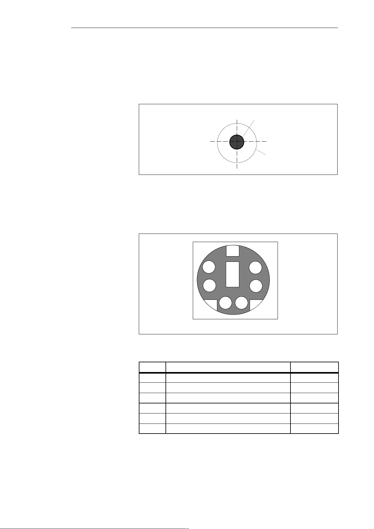
Hardware Information
8.4 Connector Pinouts
Socket Connector
for the External
Power Unit
Connecting a PS/2
Mouse
The socket for the external power supply unit has the following potentials:
+ 17.5 V +5% DC voltage
– 0 V Ground
Figure 8-1 Power Supply Connector
You can connect a PS/2 mouse to your PG 720. The connector has the
following pinout:
8-8
View of the socket connector
Figure 8-2 Connector Pinout for the PS/2 Mouse Cable
Pin No.
1 Data line Input/output
2 Not assigned –
3 0 V –
4 Current-limited 5V power supply Output
5 Clock line Input/output
6 Not assigned –
Designation Input/Output
PG 720 P Programming Device
C79000-G7076-C721-02
Page 97
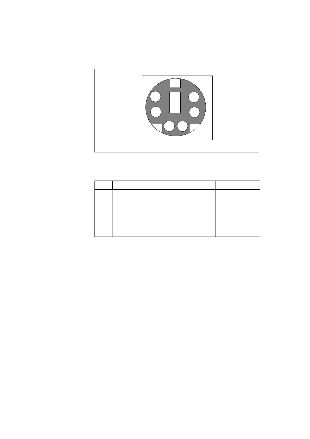
Hardware Information
Connecting an
External Keyboard
You can connect an external keyboard to your PG 720. The connector has the
following pinout:
View of the socket connector
Figure 8-3 Connector Pinout for an External Keyboard
PinNo. Designation Input/Output
1 Data line, keyboard Input/output
2 Data line, trackball Input/output
3 0V –
4 Current-limited 5V power supply Output
5 Clock line, keyboard Input/output
6 Clock line, trackball Input/output
PG 720 P Programming Device
C79000-G7076-C721-02
8-9
Page 98
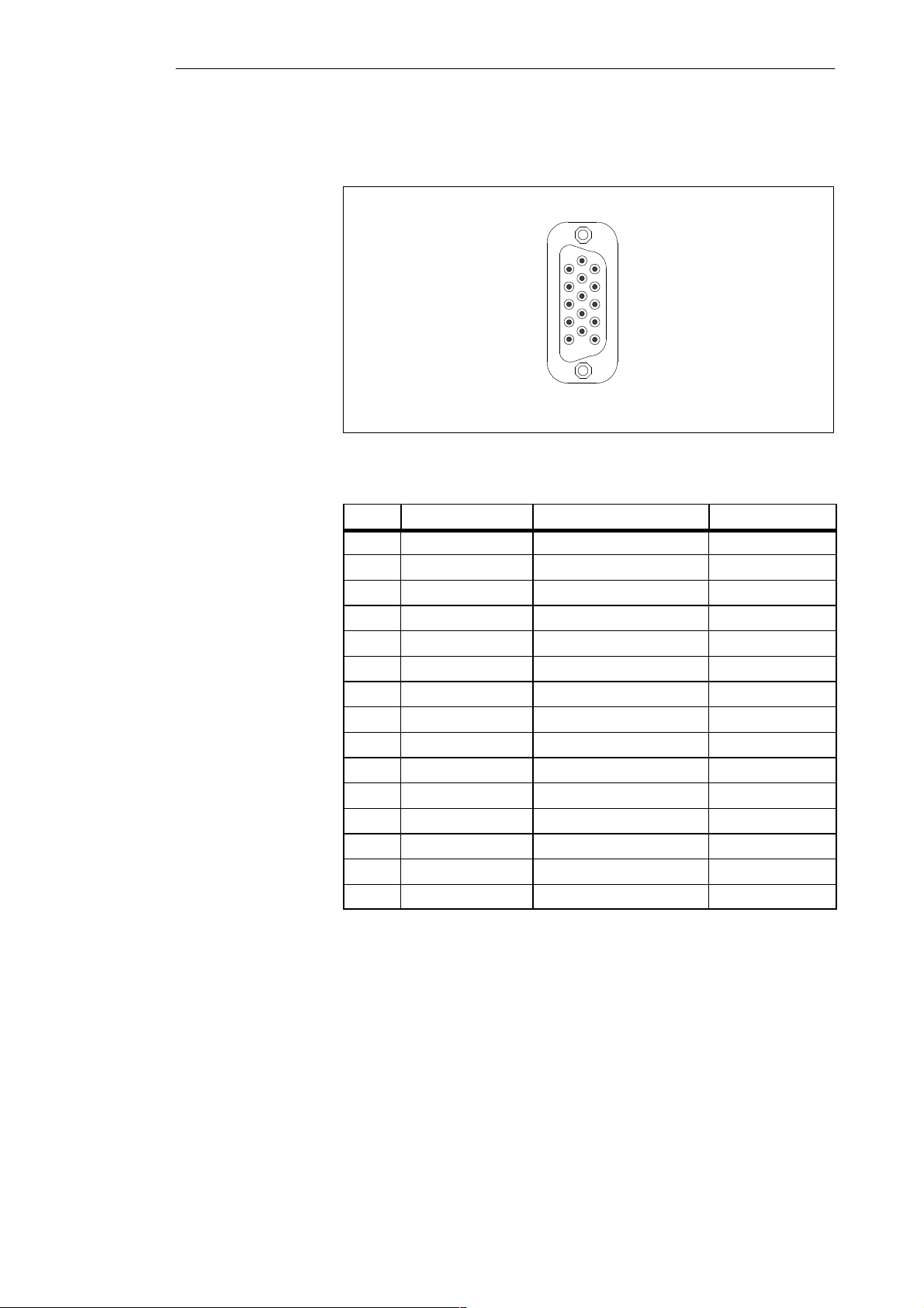
Hardware Information
VGA Socket
Connector
The VGA socket connector on the PG 720 has the following pinout:
1
11
10
5
Figure 8-4 VGA Socket Connector
Pin No. Designation Description Input/Output
1 R_EXT Red Output
2 G_EXT Green Output
3 B_EXT Blue Output
4 – NC –
5 M Ground –
6 M Ground Ground
7 M Ground Ground
8 M Ground Ground
9 – NC –
10 M Ground Ground
11 – NC –
12 – NC –
13 EXT_H Horizontal sync Output
14 EXT_V Vertical sync Output
15 – NC –
8-10
PG 720 P Programming Device
C79000-G7076-C721-02
Page 99
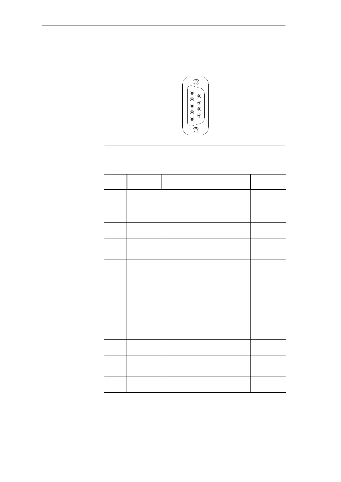
Hardware Information
MPI/DP Socket
Connector
Signal
Description
The MPI/DP socket connector on the PG 720 has the following pinout:
1
6
9
5
Figure 8-5 MPI/DP Socket Connector
Pin No.
Designation Description Input/
Output
1 NC Pin 1 is not assigned –
2 NC Pin 2 is not assigned –
3 LTG_B Signal line B of the MPI module Input/output
4 RTS_AS RTSAS, control signal for received data
stream. The control signal is “1” active
when PLC is sending.
5 M5EXT M5EXT return line (GND) of the 5 V
power supply. The current load caused
by an external user connected between
P5EXT and M5EXT must not exceed
max. 90 mA.
6 P5 EXT P5EXT power supply (+5V) of the 5 V
power supply. The current load caused
by an external user connected between
P5EXT and M5EXT must not exceed
max. 90 mA.
7 NC Pin 7 is not assigned –
8 LTG_A Signal line A of the MPI module Input/output
9 RTS_PG RTS output signal of the MPI module.
The control signal is “1” when the
programming device is sending
Shield – On connector casing –
Input
Output
Output
Output
PG 720 P Programming Device
C79000-G7076-C721-02
8-11
Page 100
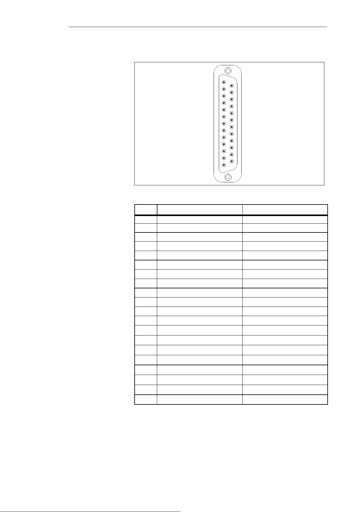
Hardware Information
Parallel Port
The parallel port (LPT1) on the PG 720 has the following pinout:
1
14
25
13
Figure 8-6 LPT1 Parallel Port (Socket)
Pin No.
1 /Strobe (CLK) Output (open collector)
2 Data - bit 0 Output (TTL level)
3 Data - bit 1 Output (TTL level)
4 Data - bit 2 Output (TTL level)
5 Data - bit 3 Output (TTL level)
6 Data - bit 4 Output (TTL level)
7 Data - bit 5 Output (TTL level)
8 Data - bit 6 Output (TTL level)
9 Data - bit 7 Output (TTL level)
10 /ACK (Acknowledge) Input (4.7 kW pull up)
11 BUSY Input (4.7 kW pull up)
12 PE (PAPER END) Input (4.7 kW pull up)
13 SELECT Input (4.7 kW pull up)
14 /AUTO FEED Output (open collector)
15 /ERROR Input (4.7 kW pull up)
16 /INIT Output (open collector)
17 /SELECT IN Output (open collector)
18 GND –
:
25 GND –
Signal Description Input/Output
8-12
PG 720 P Programming Device
C79000-G7076-C721-02
 Loading...