

Page 1
_
_
_
_
_
_
_
_
_
_
_
_
_
_
_
_
_
_
_
SIMATIC Industrial PC SIMATIC Rack PC 847B
SIMATIC
Industrial PC
SIMATIC Rack PC 847B
Operating Instructions
Introduction
_____________
Safety instructions
_____________
Description
_____________
Application planning
_____________
Installing
_____________
Connecting
_____________
Commissioning
_____________
Integration
_____________
Functions
_____________
Expansions and
programming
_____________
Maintenance and service
_____________
1
2
3
4
5
6
7
8
9
10
11
06/2008
A5E02203168-01
Interrupt, error and system
messages
_____________
Troubleshooting/FAQs
_____________
Technical data
_____________
Dimensional drawings
_____________
Detailed descriptions
_____________
Appendix
_____________
ESD directives
_____________
List of abbreviations
_____________
12
13
14
15
16
A
B
C
Page 2
Safety Guidelines
Safety Guidelines
This manual contains notices you have to observe in order to ensure your personal safety, as well as to prevent
damage to property. The notices referring to your personal safety are highlighted in the manual by a safety alert
symbol, notices referring only to property damage have no safety alert symbol. These notices shown below are
graded according to the degree of danger.
DANGER
indicates that death or severe personal injury will result if proper precautions are not taken.
WARNING
indicates that death or severe personal injury may result if proper precautions are not taken.
CAUTION
with a safety alert symbol, indicates that minor personal injury can result if proper precautions are not taken.
CAUTION
without a safety alert symbol, indicates that property damage can result if proper precautions are not taken.
NOTICE
indicates that an unintended result or situation can occur if the corresponding information is not taken into
account.
If more than one degree of danger is present, the warning notice representing the highest degree of danger will
be used. A notice warning of injury to persons with a safety alert symbol may also include a warning relating to
property damage.
Qualified Personnel
The device/system may only be set up and used in conjunction with this documentation. Commissioning and
operation of a device/system may only be performed by qualified personnel. Within the context of the safety notes
in this documentation qualified persons are defined as persons who are authorized to commission, ground and
label devices, systems and circuits in accordance with established safety practices and standards.
Prescribed Usage
Note the following:
WARNING
This device may only be used for the applications described in the catalog or the technical description and only
in connection with devices or components from other manufacturers which have been approved or
recommended by Siemens. Correct, reliable operation of the product requires proper transport, storage,
positioning and assembly as well as careful operation and maintenance.
Trademarks
All names identified by ® are registered trademarks of the Siemens AG. The remaining trademarks in this
publication may be trademarks whose use by third parties for their own purposes could violate the rights of the
owner.
Disclaimer of Liability
We have reviewed the contents of this publication to ensure consistency with the hardware and software
described. Since variance cannot be precluded entirely, we cannot guarantee full consistency. However, the
information in this publication is reviewed regularly and any necessary corrections are included in subsequent
editions.
Siemens AG
Industry Sector
Postfach 48 48
90327 NÜRNBERG
GERMANY
A5E02203168-01
Ⓟ 06/2008
Copyright © Siemens AG 2007, 2008.
Technical data subject to change
Page 3

Table of contents
1 Introduction................................................................................................................................................ 7
1.1 Preface...........................................................................................................................................7
1.2
Safety instructions ..................................................................................................................................... 9
2
2.1
Description............................................................................................................................................... 11
3
3.1
3.2
3.3
3.4
3.5
3.6
3.6.1
3.6.2
3.6.3
3.6.4
Application planning................................................................................................................................. 25
4
4.1
4.2
4.3
4.4
Guideline to the operating instructions ..........................................................................................8
General safety instructions ............................................................................................................9
Overview ......................................................................................................................................11
Areas of application .....................................................................................................................12
Highlights .....................................................................................................................................12
Function .......................................................................................................................................13
Features.......................................................................................................................................14
Installation....................................................................................................................................18
External structure.........................................................................................................................18
Operator Controls ........................................................................................................................19
Connecting elements ...................................................................................................................20
Status displays.............................................................................................................................22
Transport......................................................................................................................................25
Unpacking and checking the delivery unit ...................................................................................25
Ambient and environmental conditions........................................................................................27
Access protection.........................................................................................................................28
Installing .................................................................................................................................................. 29
5
5.1
Connecting .............................................................................................................................................. 31
6
6.1
6.2
6.3
6.4
Commissioning ........................................................................................................................................ 37
7
7.1
7.2
7.3
7.4
SIMATIC Rack PC 847B
Operating Instructions, 06/2008, A5E02203168-01
Installing the device .....................................................................................................................29
Connecting peripherals ................................................................................................................31
Connecting the device to power...................................................................................................32
Equipotential bonding ..................................................................................................................34
Connecting PROFINET strain relief.............................................................................................35
Requirements for commissioning.................................................................................................37
Initial Commissioning - Initial Startup...........................................................................................37
Windows XP, Vista Security Center.............................................................................................38
Notes on operation.......................................................................................................................39
3
Page 4

Table of contents
7.4.1 DVD burner ................................................................................................................................. 39
7.4.2 Removable hard disks................................................................................................................. 40
7.4.3
7.4.4
Integration................................................................................................................................................ 53
8
2HDD system (optional).............................................................................................................. 42
RAID system ............................................................................................................................... 43
8.1
8.2
Functions................................................................................................................................................. 57
9
9.1
9.2
9.3
9.4
9.5
9.6
Expansions and programming ................................................................................................................. 61
10
10.1
10.2
10.2.1
10.3
10.3.1
10.3.2
10.4
10.4.1
10.4.2
10.4.3
10.4.4
Integration ................................................................................................................................... 53
PROFINET .................................................................................................................................. 55
Overview of the monitoring functions.......................................................................................... 57
Temperature monitoring/display ................................................................................................. 57
Watchdog (WD)........................................................................................................................... 58
Fan monitoring ............................................................................................................................ 59
RAID monitoring.......................................................................................................................... 59
Safecard on Motherboard (SOM)................................................................................................ 60
Open the device .......................................................................................................................... 61
Memory expansion...................................................................................................................... 63
Installing memory modules ......................................................................................................... 63
Installing expansion cards........................................................................................................... 66
Notes on the modules ................................................................................................................. 66
Installing an expansion module................................................................................................... 67
Installing drives ........................................................................................................................... 68
Options of installing disk drives................................................................................................... 68
Installing and removing disk drives in the front drive bay ........................................................... 70
Installing and removing drives in the front drive bay................................................................... 72
Installing / removing hard disk drives in the fixed hard disk rack................................................ 74
Maintenance and service......................................................................................................................... 75
11
11.1
11.1.1
11.1.2
11.1.3
11.1.4
11.1.5
11.1.6
11.1.7
11.1.8
11.1.9
11.1.10
11.2
11.2.1
11.2.2
11.2.3
11.2.3.1
11.2.3.2
11.2.4
11.2.5
SIMATIC Rack PC 847B
Removing and installing hardware components ......................................................................... 75
Repairs........................................................................................................................................ 75
Preventive maintenance.............................................................................................................. 76
Replacing filters........................................................................................................................... 76
Removing the device / drive cooling fan ..................................................................................... 77
Replacing the backup battery ..................................................................................................... 81
Removing the power supply module........................................................................................... 83
Removing the bus board............................................................................................................. 84
Removing the Operator Panel .................................................................................................... 85
Removing the motherboard......................................................................................................... 85
Processor replacement ............................................................................................................... 87
Reinstalling the software............................................................................................................. 90
General installation procedure .................................................................................................... 90
Restoring the Factory State of the Software Using the Restore DVD ........................................ 91
Installing Windows ...................................................................................................................... 92
Setting up partitions for Windows 2000, XP, Server 2003 operating systems ........................... 93
Installing Microsoft Windows operating systems ........................................................................ 95
Setting up the language selection by means of the Multilanguage User Interface (MUI)........... 97
Recovery of Windows Vista ........................................................................................................ 98
4 Operating Instructions, 06/2008, A5E02203168-01
Page 5

Table of contents
11.2.6 Installing drivers and software ...................................................................................................101
11.2.7 Installing the RAID Controller software......................................................................................101
11.2.8
11.2.9
11.2.9.1
11.2.9.2
11.2.10
11.2.10.1
11.2.11
Interrupt, error and system messages ................................................................................................... 105
12
Installing burner/DVD software ..................................................................................................101
Installing updates .......................................................................................................................102
Updating the operating system ..................................................................................................102
Installing or updating application programs and drivers ............................................................102
Data backup...............................................................................................................................103
Creating an image......................................................................................................................103
CP 1616 onboard.......................................................................................................................104
12.1
12.2
Troubleshooting/FAQs........................................................................................................................... 109
13
13.1
13.2
Technical data ....................................................................................................................................... 113
14
14.1
14.2
14.3
14.4
Dimensional drawings............................................................................................................................ 121
15
15.1
15.2
15.3
Detailed descriptions ............................................................................................................................. 125
16
16.1
16.1.1
16.1.2
16.1.3
16.1.4
16.1.5
Boot error messages..................................................................................................................105
BIOS POST codes .....................................................................................................................107
General problems ......................................................................................................................109
Problems when Using Modules of Third-party Manufacturers...................................................112
General specifications................................................................................................................113
Power requirements of components (maximum values) ...........................................................119
Power supply (AC) .....................................................................................................................120
Technical data of the telescopic rails.........................................................................................120
Dimensional drawing of the device ............................................................................................121
Dimensional drawing for the use of telescopic rails...................................................................122
Dimensional drawings for installation of expansion modules ....................................................123
Motherboard...............................................................................................................................125
Structure and functions of the motherboard ..............................................................................125
Technical features of the motherboard ......................................................................................126
Position of the interfaces on the motherboard...........................................................................128
External interfaces .....................................................................................................................129
Internal ports ..............................................................................................................................138
16.2
16.2.1
16.2.2
16.2.3
16.2.4
16.3
16.3.1
16.3.2
16.4
16.4.1
16.4.2
16.4.2.1
16.4.2.2
16.4.2.3
SIMATIC Rack PC 847B
Operating Instructions, 06/2008, A5E02203168-01
Bus board...................................................................................................................................145
Bus board - Layout and principle of operation...........................................................................145
Exclusive PCI hardware interrupt...............................................................................................148
Pin assignment of the bus board connectors.............................................................................149
Pinout for PCI Express slot x4 (slots 2, 3, 4) .............................................................................153
Displays and operator panel ......................................................................................................154
Operating panel - Layout and function.......................................................................................154
Pin assignment of the OP connectors .......................................................................................154
System resources ......................................................................................................................155
Currently allocated system resources........................................................................................155
System resources used by the BIOS/DOS ................................................................................156
I/O address allocation ................................................................................................................156
Interrupt assignments ................................................................................................................158
Memory address assignments ...................................................................................................159
5
Page 6

Table of contents
16.5 BIOS Setup ............................................................................................................................... 160
16.5.1 Overview ................................................................................................................................... 160
16.5.2
16.5.3
16.5.4
16.5.5
16.5.6
16.5.7
16.5.8
16.5.9
16.5.10
16.5.11
Starting BIOS Setup.................................................................................................................. 161
BIOS Setup menus ................................................................................................................... 162
Main menu................................................................................................................................. 164
Advanced Menu ........................................................................................................................ 176
Security menu ........................................................................................................................... 183
Power menu .............................................................................................................................. 185
Boot menu................................................................................................................................. 186
Version menu ............................................................................................................................ 188
Exit menu .................................................................................................................................. 189
Default BIOS Setup entries....................................................................................................... 190
16.6
16.6.1
16.6.1.1
16.6.1.2
16.6.2
16.6.2.1
16.6.3
Appendix................................................................................................................................................ 201
A
A.1
A.2
A.3
A.4
ESD directives....................................................................................................................................... 209
B
B.1
List of abbreviations............................................................................................................................... 211
C
C.1
Glossary ................................................................................................................................................ 217
Index...................................................................................................................................................... 227
Communication processor CP 1616 onboard........................................................................... 194
Introduction ............................................................................................................................... 194
Network connections................................................................................................................. 194
Typical Communication Partners .............................................................................................. 195
Firmware loader ........................................................................................................................ 197
Loading firmware....................................................................................................................... 198
Further actions in STEP 7/NCM PC.......................................................................................... 200
Guidelines and Declarations ..................................................................................................... 201
Certificates and Approvals ........................................................................................................ 203
Service and support .................................................................................................................. 205
Retrofitting instructions.............................................................................................................. 206
ESD guidelines.......................................................................................................................... 209
Abbreviations ............................................................................................................................ 211
SIMATIC Rack PC 847B
6 Operating Instructions, 06/2008, A5E02203168-01
Page 7

Introduction
1.1 Preface
Purpose of this documentation
These operating instructions contain all the information you need to commission and use the
SIMATIC Panel PC 847B.
It is aimed at both programmers and testers who are commissioning the device themselves
and are combining the device with other units (automation systems, programming devices),
as well as service and maintenance technicians installing expansions or undertaking fault
analysis.
Scope of this documentation
This documentation is valid for all variations of SIMATIC Box PC 847B and describes
delivery conditions as of June 2008.
Position in the information landscape
These operating instructions are available on the "Documentation and Drivers" CD included
with your product.
1
For supplementary instructions on how to handle the software, please refer to the
corresponding manuals.
Conventions
The term Rack PC or device is also used within this documentation as abbreviation of the
product name SIMATIC Rack PC 847B. The abbreviations CP will be used for
CP 1616 onboard and Vista for Windows Vista Ultimate.
History
The following releases of the operating instructions have previously been published:
Edition Comment
02/2007 First Edition
01/2008
06/2008
SIMATIC Rack PC 847B
Operating Instructions, 06/2008, A5E02203168-01
• Remedy
• New operating system: Windows Vista Ultimate
• Remedy
• New function: CP 1616 onboard
7
Page 8

Introduction
1.2 Guideline to the operating instructions
1.2 Guideline to the operating instructions
Content structure Contents
Table of contents Detailed organization of the documentation, including the index of pages and chapters
Introduction Purpose, layout and description of the important topics.
Safety instructions Covers all general safety-related aspects of statutory regulations in terms of the installation,
commissioning and operation of the product/system.
Description Fields of application, features and installation of the product/system
Application planning Aspects of storage, transport, environmental and EMC conditions to be considered in the
preparatory stage
Installing Product installation options and installation instructions
Connecting Options of connecting the product and wiring instructions
Commissioning Commissioning the product/system.
Integration Options of integrating the product into existing or planned system environments/networks.
Functions Monitoring and display functions
Expansions / Programming Installation of expansion devices (memory, modules, drives)
Maintenance and service Replacement of hardware components, restoring and setup of the operating system,
installation of drivers and software
Troubleshooting Problems, cause, remedy
Technical data General specifications in compliance with relevant standards and current/voltage values
Dimensional drawings Dimensions of the device and of modules
Detailed descriptions Structure, function and features of vital components, distribution of system resources and
use of the BIOS Setup routine
Appendix Guidelines and certifications, service and support, notes on retrofitting
ESD directives General ESD directives.
SIMATIC Rack PC 847B
8 Operating Instructions, 06/2008, A5E02203168-01
Page 9
Safety instructions
2.1 General safety instructions
Opening the device / repairs
CAUTION
Please observe the safety instructions on the back of the cover sheet of this
documentation. You should not expand your device unless you have read the relevant
safety instructions.
This device is compliant with relevant safety directives to IEC, VDE, EN and UL. If you have
questions about the validity of the installation in the planned environment, please contact
your service representative.
Only authorized technical personnel are allowed to repair device components.
2
System expansions
WARNING
Unauthorized opening and improper repairs can cause considerable damage to property or
danger for the user.
Only install system expansion devices designed for this device. Installation of other
expansions may damage the system or violate safety requirements and RF interference
suppression regulations. Contact your technical support team or where you purchased your
PC to find out which system expansion devices may safely be installed.
CAUTION
If you install or exchange system expansions and damage your device, the warranty
becomes void.
SIMATIC Rack PC 847B
Operating Instructions, 06/2008, A5E02203168-01
9
Page 10
Safety instructions
2.1 General safety instructions
Battery
This device is equipped with a Lithium battery. Batteries may only be replaced by qualified
personnel.
ESD directives
CAUTION
There is the risk of an explosion if the battery is not replaced as directed. Replace only with
the same type or with an equivalent type recommended by the manufacturer. Dispose of
used batteries in accordance with local regulations.
WARNING
Risk of explosion and release of harmful substances!
Therefore, do not throw Lithium batteries into an open fire, do not solder or open the cell
body, do not short-circuit or reverse polarity, do not heat up above 100° C, dispose of in
accordance with regulations and protect against direct exposure to sunlight, moisture and
condensation.
Modules containing electrostatic sensitive devices (ESDs) can be identified by the following
label:
Strictly follow the guidelines mentioned below when handling modules which are sensitive to
ESD:
● Always discharge your body´s static electricity before handling modules that are sensitive
to ESD (for example, by touching a grounded object).
● All devices and tools must be free of static charge.
● Always pull the mains connector and disconnect the battery before you install or remove
modules which are sensitive to ESD.
● Handle modules fitted with ESDs by their edges only.
● Do not touch any wiring posts or conductors on modules containing ESDs.
SIMATIC Rack PC 847B
10 Operating Instructions, 06/2008, A5E02203168-01
Page 11

Description
3.1 Overview
SIMATIC Rack PC 847B is an industrial PC in 19" rack format (4HU) with high-performance
industrial functionality.
● Wide range of expansion options
● High degree of ruggedness
● Extensive product continuity
3
Figure 3-1 SIMATIC Rack PC 847B
SIMATIC Rack PC 847B
Operating Instructions, 06/2008, A5E02203168-01
11
Page 12

Description
3.2 Areas of application
3.2 Areas of application
SIMATIC Rack PCs provide a high-performance and highly flexible 19" rack PC platform to
machine, systems and control cabinet engineering for machine-oriented industrial
applications:
● Automatic measurement and control systems for controlling process and machine data
● Visualization of production sequences and processes
● Computing and processing of images for QC
● Data acquisition and management
The SIMATIC Rack PC is certified to CE for industrial applications.
3.3 Highlights
Highlights of the SIMATIC Rack PC 847B
Highly compatible to industrial standards:
● High operational vibration and shock resistance
● Wide operational temperature range
● High service friendliness
● Distinct diagnostic features
High-performance industrial functionality:
● Integrated PROFIBUS DP / MPI interface (optional)
● Integrated PROFINET interface CP 1616 onboard (optional)
● PCI-, PCIe x1-, PCIe x16 slots
● High flexibility and expansibility of components
High investment security:
● High continuity of the components/design
● Guaranteed spare parts availability for at least 5 years
High system availability:
● SIMATIC PC DiagMonitor – PC diagnostics/message software by way of
OPC/SNMP/LAN
● SIMATIC PC/PG Image Creator – data imaging software
● RAID1 – redundant data storage to two hard disk volumes protects against data loss
SIMATIC Rack PC 847B
12 Operating Instructions, 06/2008, A5E02203168-01
Page 13

Description
3.4 Function
3.4 Function
● Integrated programmable monitoring functions (program execution (watchdog), internal
housing temperature, fan speed)
● Enhanced diagnostic/messaging by way of Ethernet, E-mail, SMS, and for direct input in
SIMATIC software by way of OPC (optional using SIMATIC PC DiagMonitor):
– Operating hours counter
– Hard disk status
– System status (heartbeat)
– Automatic logging of all messages to a log file
– Option of remote monitoring of networked SIMATIC PCs
● RAID1 for automatic data mirroring on two hard disk volumes
SIMATIC Rack PC 847B
Operating Instructions, 06/2008, A5E02203168-01
13
Page 14

Description
3.5 Features
3.5 Features
General features
Design
Enclosure
Drive bays
Slots for expansion cards
Graphics
Interfaces
PROFIBUS/MPI 12 Mbps (isolated potential, compatible to CP 5611); optional
PROFINET 10/100 Mbps (CP 1616 onboard), three RJ45; optional
Ethernet 2x 10/100/1000 Mbps (two RJ45)
USB 2 x front panel, 4 x rear panel; (high current)
Serial COM1 (V.24), COM2 (V.24) 9-pin
Parallel LPT1
Monitor 1 x VGA
Keyboard PS/2
Mouse PS/2
Audio Microphone, Line out / Headset
• 19” rack, 4 HU
• Rugged panel-mount housing, all metal
• Prepared for mounting telescopic rails
• Horizontal and vertical mounting position is possible
• Tower installation by means of Tower Kit
• Lockable front cover as access protection
• Dust protection by means of overpressure ventilation using
bearing seated front fan through filter
• Enclosure cover fastened with a single screw
• Front fan can be exchanged without tools
• Card retainer for reliable operation of PC modules under
vibration and shock conditions
• Front: 3 x 5.25" and 1 x 3.5"
• Internal: 2 x 3.5" (fixed installation or in vibration-damping
drive bracket)
• 7 x PCI long
1)
• 1 x PCI Express x16 long (PEG for graphics modules
• 3 x PCI Express x4 long (optional)
for max. 11 modules at same time
• Onboard Intel® GMA950 graphics controller
2-D and 3-D engine integrated in chipset,
Dynamic Video Memory Technology
(uses up to 128 MB of RAM)
Max. 1280x1024 at 100 Hz / 32-bit color depth
Max. resolution:
2038x1536 at 75 Hz / 16-bit color depth
• in PCIe x16 slot (optional)
PCIe x16 graphics card (dual head: 2 x VGA or 2
x DVI-D),
128 MB RAM
up to 2048x1536 pixels at 75 Hz / 32-bit color depth
Wake on LAN and Remote Boot supported
1)
)
SIMATIC Rack PC 847B
14 Operating Instructions, 06/2008, A5E02203168-01
Page 15
Description
3.5 Features
General features
Power supply 100 VAC to 240 VAC, wide range; with short-term power
failure backup in accordance with NAMUR: Max. 20 ms at
0.85 rated voltage
1)
The modules should not occupy more than one slot
Monitoring functions
Temperature
Fan
Watchdog
Status LEDs
• Overshoot/undershoot of permissible operating
temperature
• Messages can be evaluated by the application program.
• Speed monitoring
• Messages can be evaluated by the application program.
• Monitoring of program execution
• Monitoring time can be parameterized in software
• Restart can be parameterized in the event of a fault
• Messages can be evaluated by the application program.
• POWER (internal power supply unit, PC switched On)
• HDD (access to hard disk drive)
• ETHERNET 1, ETHERNET 2 (Ethernet status)
• PROFIBUS/MPI (activation display of the PROFIBUS/MPI
interface, optional product feature)
• SF PROFINET (status display of the CP 1616 onboard
interface, optional product feature)
• WATCHDOG (Watchdog function/error display)
• TEMP (temperature status)
• FAN (speed monitoring)
• HDD1, HDD2 Alarm RAID status message in conjunction
with SIMATIC monitoring software (only with RAID option)
Basic variant
CPU motherboard Motherboard without Fieldbus
Bus module 8 slots (7 x PCI, 1 x PCIe x16)
Processor Intel® Core™2 Duo T7400 (2.16 GHz, 667 MHz FSB, 4 MB
RAM expansion 256 MB SDRAM DDR2 667 (PC 5300)
Drives
Floppy drive 1.44 MB
Hard disks 80 GB SATA, 3.5", internal installation
Operating system without
SIMATIC Rack PC 847B
Operating Instructions, 06/2008, A5E02203168-01
Second Level Cache, EM64T, VT)
Single channel
2 x SO DIMM slots for max. 4 GB
15
Page 16

Description
3.5 Features
Optional accessories
Processor
RAM expansion Up to 4 GB, dual-channel
PROFIBUS/MPI 12 Mbps (isolated potential, compatible to CP 5611)
PROFINET 10/100 Mbps (CP 1616 onboard, three RJ45)
Drives
DVD ROM Read:
DVD burner Read:
Hard disks 3.5" (SATA)
Graphics controllers
Operating system Preinstalled / supplied on Restore DVD
• Intel® Core™2 Duo T5500 (1.66 GHz, 667 MHz FSB,
2 MB Second Level Cache, EM64T)
• Intel® Celeron® M 440 (1.86 GHz, 533 MHz FSB, 1 MB
Second Level Cache)
DVD ROM: Single layer 16x, Dual Layer 8x
DVD+R/RW, DVD-R/RW 8x, DVD-RAM 2x
CD-ROM: CD-R 32x, CD-RW 20x
DVD ROM: Single Layer 16x, Dual Layer 12x
DVD-R/+R: Single Layer 16x, Dual Layer 7x
DVD-RW/+RW 13x
CD-ROM: CD-R 48x, CD-RW 40x
Write:
DVD+R 16x, DVD+RW 8x, DVD-R 16x, DVD-RW 6x,
DVD+R9 (DL) 8x, DVD-R DL 8x
CD-R 48x, CD-RW 32x
Installation in internal drive bay (fixed or vibration-damping)
• 160 GB;
• 2 x 160 GB;
• RAID1, 2 x 160 GB (mirror disks)
Installation in the front bracket of the exchangeable rack
• 80 GB
• 160 GB
• 2 x 160 GB;
• RAID1, 2 x 160 GB (mirror disks)
• Add2 card (1x DVI-D)
• PCIe x16 graphics card, dual head (2x VGA or 2x DVI-D)
• Windows 2000 Professional MUI*
• Windows XP Professional MUI*
• Windows Server 2003 MUI
• Windows Vista Ultimate
*MUI: Multi language User Interface; 5 languages (German,
English, French, Spanish, Italian)
SIMATIC Rack PC 847B
16 Operating Instructions, 06/2008, A5E02203168-01
Page 17
Description
3.5 Features
Languages that can be installed from operating system recovery CD / DVD
Language Windows 2000 Windows XP Windows Server 2003 Windows Vista
German X X X X
English X X X X
French X X X X
Italian X X X X
Spanish X X X X
Japanese X X X
Chinese (Hong Kong) X X
Chinese (simplified) X X
Chinese (Taiwan) X
Korean X
Optional expansions
SIMATIC PC
DiagMonitor SW
SIMATIC PC
Image Creator SW
Software tool for monitoring local and remote SIMATIC PCs:
• Watchdog
• Temperature
• Fan speed
• Hard disk monitoring (SMART, RAID status)
• System / Ethernet monitoring (Heartbeat)
Software tool for saving data locally
SIMATIC Rack PC 847B
Operating Instructions, 06/2008, A5E02203168-01
17
Page 18

Description
3.6 Installation
3.6 Installation
3.6.1 External structure
Front view of the device (example) Item Description
(1) Front panel with vent openings
(filter mat and fan behind the front
panel). Check the filter mat
regularly for soiling and, if
appropriate, replace it.
(2) Status displays
(3) Cover screws
(4) On/off button
(5) Reset button
(6) Lock
(7) Features for the installation of
DVD ROM drives, DVD burners
and exchangeable racks
(8) Drive bay for floppy disk drive
(9) 2 x USB interface
(10) Lockable front door for access
security. Keep the front door
closed during normal operation.
Rear view of the device (example) Item Description
(1) Rear drive cooling fan
(2) Fan / power supply unit
(3) Expansion slots
(4) Connection elements
(5) Power supply connector
SIMATIC Rack PC 847B
18 Operating Instructions, 06/2008, A5E02203168-01
Page 19
Description
3.6 Installation
3.6.2 Operator Controls
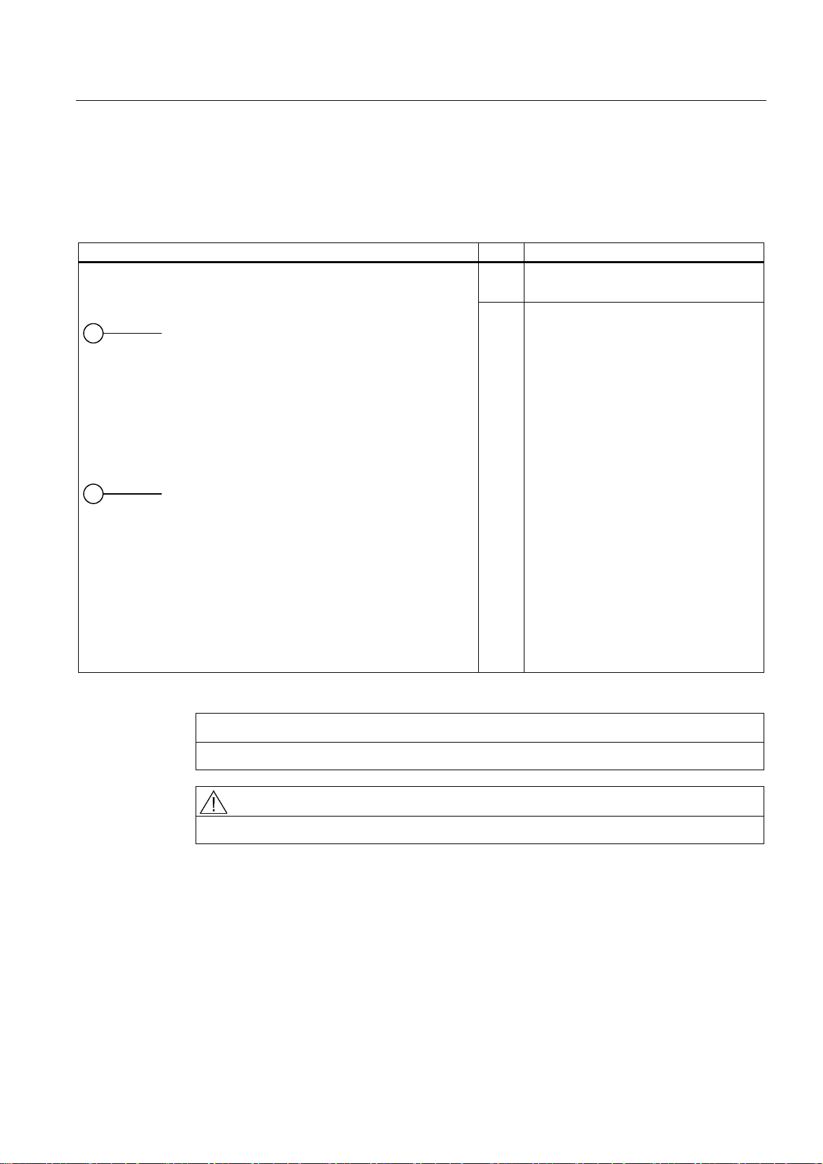
Control elements, On/Off and Reset buttons Item Description
(1) On/off button
For switching the device on or off
(2) Reset button
The reset button can be operated using a
pointed object or a paper clip, for
example. The button signal triggers a
hardware reset. The PC performs a
restart (cold start).
CAUTION
Data may be lost when the PC performs a hardware reset.
WARNING
The on/off button signal does not cut off power to the PC!
SIMATIC Rack PC 847B
Operating Instructions, 06/2008, A5E02203168-01
19
Page 20
Description
3.6 Installation
3.6.3 Connecting elements
Interfaces
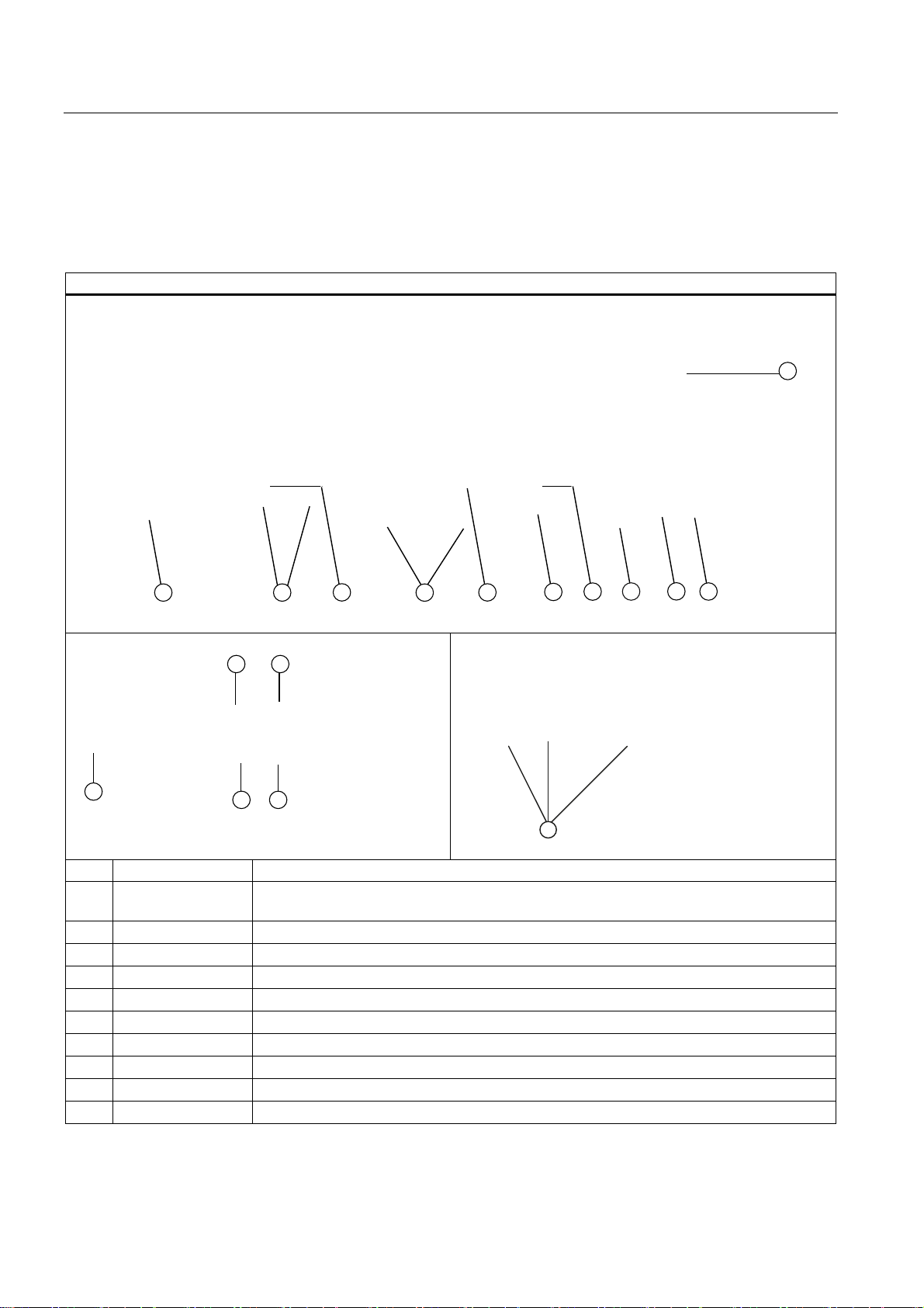
Layout of the interfaces on the rear of the device
Item Designation Description
(1) DVI or
DMS59
DVI-D connector of the ADD2 card for digital monitors (optional) or
DMS59 connector for Dual Head graphics card (optional).
(2) Audio (input) Connectors for analog audio source, microphone, 3.5 mm phono jack
(3) Audio (output) Connector for active speakers or headset, 3.5 mm phono jack
(4) VGA Connection for VGA monitor
(5) MOUSE Connection for a PS/2 mouse
(6) KEYBOARD Connection for a PS/2 keyboard
(7) LPT Parallel interface, 25-pin
(8) COM Serial interface(V.24), 9-pin sub D plug
(9) ETHERNET 1, 2 * 2 x RJ45 connectors, Ethernet 10/100/1000 Mbps
(10) USB USB device connectors. USB ports 1 to 4
SIMATIC Rack PC 847B
20 Operating Instructions, 06/2008, A5E02203168-01
Page 21

Description
3.6 Installation
Layout of the interfaces on the rear of the device
(11)
(12) VGA VGA connections
(13) DVI-I DVI-I connection
(14) Dual-head adapter Connector on dual-head graphics card (optional)
PROFIBUS/MPI
PROFINET CP 1616 onboard interface, three RJ45 sockets (optional product version)
PROFIBUS interface (RS 485, electrically isolated), 9-pin D-sub socket (optional product
characteristic)
* For unique labeling, the LAN interfaces are numbered on the enclosure. The operating system
numbering may deviate from this.
Power supply
Position of the IEC connector Description
IEC connector for the AC power supply to the
device. The permitted power range is
100 VAC to 240 VAC.
SIMATIC Rack PC 847B
Operating Instructions, 06/2008, A5E02203168-01
21
Page 22

Description
3.6 Installation
3.6.4 Status displays
Front status displays
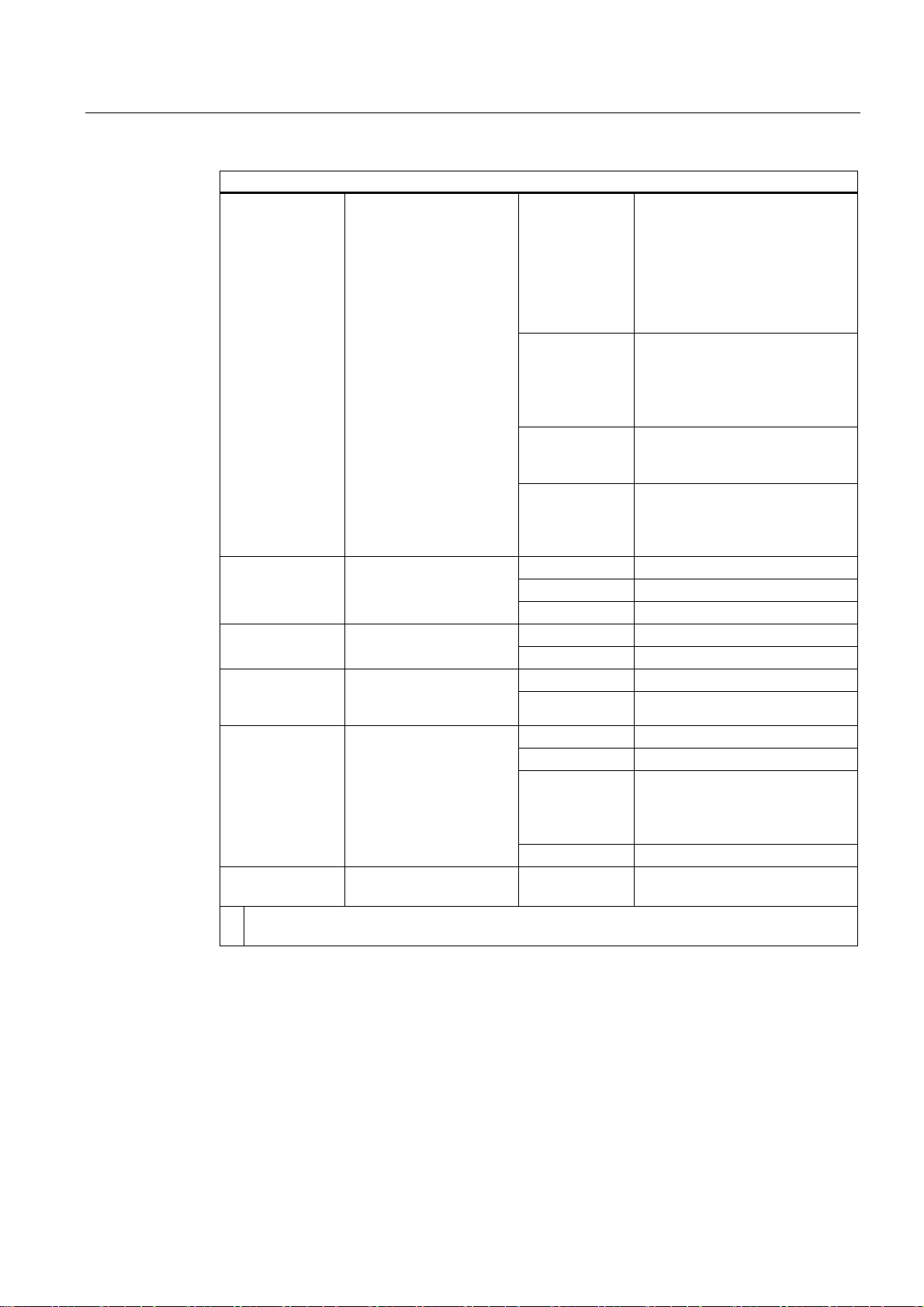
Display Meaning LEDs Description
POWER PC status display
access
ETHERNET 1 * ETHERNET status
display
ETHERNET 2 * ETHERNET status
display
PROFIBUS/MPI
(optional)
Display of the
communication status to
S7 or PROFIBUS
OFF isolated from mains
YELLOW Standby (hibernating)
GREEN PC in operation
OFF no access HDD Display for hard disk
GREEN Access
OFF
GREEN Data traffic
OFF
GREEN Data traffic
OFF
GREEN Data traffic
• No connection
• No data traffic
• No connection
• No data traffic
• No connection
• No data traffic
SIMATIC Rack PC 847B
22 Operating Instructions, 06/2008, A5E02203168-01
Page 23
Description
3.6 Installation
Front status displays
SF PROFINET
(optional)
WATCHDOG WATCHDOG status
HDD1 ALARM
HDD2 ALARM
All displays are lit Error in early BIOS Post All lit CPU startup failure
* For unique labeling, the LAN interfaces are numbered on the enclosure. The operating system
numbering may deviate from this.
Status display for
CP 1616 onboard
display
monitoring
active SOM or
DiagMonitor software)
Hard disk alarm in
conjunction with RAID
and monitoring software
OFF
Flashes slowly
Flashes rapidly Exception error: diagnostics via
AN
OFF WATCHDOG not activated
GREEN WATCHDOG monitoring enabled
RED Monitoring time elapsed
OFF Internal temperature OK TEMP Internal temperature
RED Internal temperature critical
OFF Fan speed OK FAN Fan status (only with
RED Fan speed too low
OFF RAID is OK
One RED HDD1 or HDD2 not OK
Both RED RAID not OK
Both flash RAID is synchronized
• CP not available
• CP disabled
• No error, communication
established
• Charging in progress
• CP 1616 driver not installed
• CP in NDIS mode
• Link status error
• IO controller: IO device cannot
be addressed
• IO controller: Duplicate IP
address
Web or SNMP is no longer
possible
• Diagnostics information
available
• No communication
established.
(for information on locating the
faulty HDD, refer to the RAID
system section)
Error in early POST
SIMATIC Rack PC 847B
Operating Instructions, 06/2008, A5E02203168-01
23
Page 24
Description
3.6 Installation
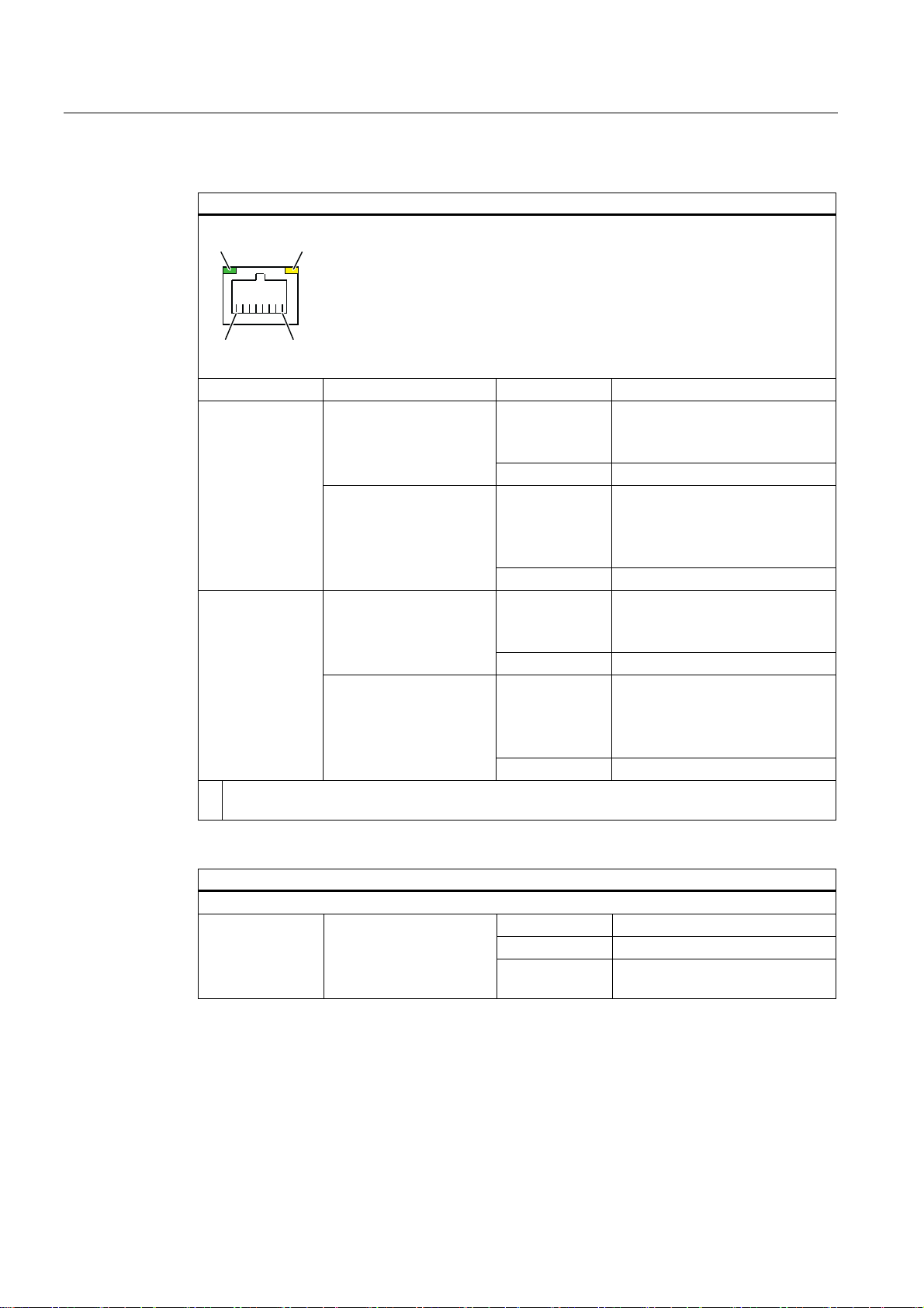
Rear status displays
/(' /('
Display Meaning LED Description
Ethernet LAN 1, 2
*
PROFINET LAN
X1, P1, P2, P3 *
* For unique labeling, the LAN and PROFINET interfaces are numbered on the housing. The
numbering by the operating system may deviate from this.
Green LED
Link status display
Yellow LED
Activity status display
Green LED
Link status display of CP
1616 channel
Yellow LED
Activity status display of
CP 1616 channel
OFF
GREEN Active cable connected
OFF
YELLOW Data transfer active
OFF
GREEN Active cable connected
OFF
YELLOW Data transfer active
• No cable connected
• Cable disabled
• Interface disabled
• No cable connected
• Cable disabled
• Interface disabled
• No activity
• No cable connected
• Cable disabled
• Interface disabled
• No cable connected
• Cable disabled
• Interface disabled
• No activity
Virtual status displays
The two "virtual" CP 1616 LEDs are only visible in the SIMATIC software and can be read via SNMP.
PROFINET Virtual LEDs
SIMATIC Rack PC 847B
24 Operating Instructions, 06/2008, A5E02203168-01
RUN CP is active
STOP CP is in the stop state
Flashes The states "flashes slowly" or
"flashes rapidly" do not exist.
Page 25

Application planning
4.1 Transport
Despite the device's rugged design, its internal components are sensitive to severe
vibrations or shock. You must therefore protect the PC from severe mechanical stress when
transporting it.
You should always use the original packaging for shipping and transporting the device.
CAUTION
Risk of damage to the device!
When transporting the PC in cold weather, it may be submitted to extreme variations in
temperature. In this situation, ensure that no moisture (condensation) develops on or inside
the device.
If condensation has developed on the device, wait at least 12 hours before you switch it on.
4
4.2 Unpacking and checking the delivery unit
Unpacking the device
Note the following points when you unpack the unit
● It is advisable not to dispose of the original packing material. Keep it in case you have to
transport the unit again.
● Please keep the documentation in a safe place. It is required for initial commissioning and
is part of the device.
● Check the delivery unit for any visible transport damage.
● Verify that the shipment contains the complete unit and your separately ordered
accessories. Please inform your local dealer of any disagreements or transport damage.
● Please inform Siemens AG by means of the enclosed SIMATIC IPC/PG quality control
report form.
SIMATIC Rack PC 847B
Operating Instructions, 06/2008, A5E02203168-01
25
Page 26
Application planning
4.2 Unpacking and checking the delivery unit
Noting down the device identification data
The device can be clearly identified with the help of this identification data in case of repairs
or theft.
Enter the following data in the table below:
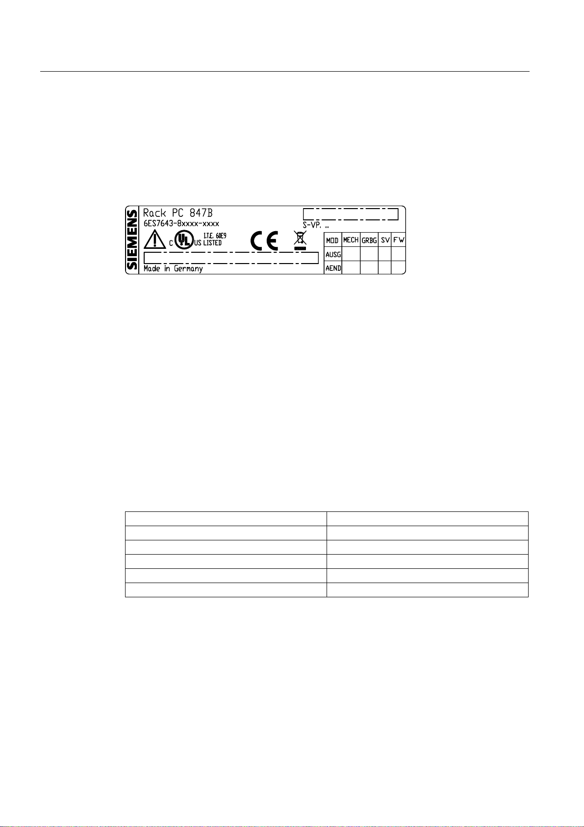
● Serial number: The serial number (S VP) is located on the rating plate either on the rear
panel of the device or on the inside of the front door.
Figure 4-1 Rating plate
● Order number of the device
● Ethernet address: The Ethernet address of the device is available in BIOS Setup (F2
function key) , at Info > (F1 function key) > LAN Address.
Device equipment
● Microsoft Windows "Product Key" on the "Certificate of Authenticity" (COA). The COA
label is attached to the inside of the front door.
You may need the Product Key in case you reinstall the operating system.
Figure 4-2 COA label
Serial number: S VP ...
Order no. 6ES7643-8...
Microsoft Windows Product Key
Ethernet 1 address
Ethernet 2 address
CP 1616 onboard layer 2
The device equipment is listed on the inner side of the front door.
SIMATIC Rack PC 847B
26 Operating Instructions, 06/2008, A5E02203168-01
Page 27
Application planning
4.3 Ambient and environmental conditions
4.3 Ambient and environmental conditions
When you plan your project, you should make allowances for:
● Observe the climatic and mechanical environmental conditions in the technical data in
your operating instructions.
● Avoid extreme ambient conditions as far as possible. Protect your device against dust,
moisture and heat.
● The device is designed for use in normal industrial environments to IEC 60721-3-3
(pollutant class 3C2 for chemical influence, 3S2 for sand and dust.) SIMATIC Rack PCs
may not be operated in severe environments which are subject to caustic vapors or
gases without taking additional protective measures (such as the provision of clean air.)
● Do not expose the device to direct sunlight.
● Install the device in such a way that it poses no danger, for example, by falling over.
● The device conforms to protection class IP41 at the front panel. Ensure that the
installation opening for the device is splash-proof in areas which may be subject to splash
water.
● Always maintain a minimum clearance of 50 mm to the area of the ventilation slots in
order to ensure adequate ventilation of the PC.
● Do not cover the ventilation slots of the enclosure.
● The device meets requirements for fire protection housings to EN 60950-1 and can be
installed without additional fire protection enclosure.
● The connected or built-in peripherals should not introduce a counter emf in excess of
0.5 V into the device.
WARNING
Failure to comply with these requirements for system installation shall render approvals
to UL 60950-1, EN 60950-1 void and leads to the risk of overheating and injury!
SIMATIC Rack PC 847B
Operating Instructions, 06/2008, A5E02203168-01
27
Page 28

Application planning
4.4 Access protection
4.4 Access protection
The access protection of the rack PC is only enabled if the front door is locked.
SIMATIC Rack PC 847B
28 Operating Instructions, 06/2008, A5E02203168-01
Page 29

Installing
5.1 Installing the device
Optional installation locations
The device can be mounted horizontally or vertically in control desks, switching cabinets and
19" rack systems.
Optional mounting methods
Options of mounting the device
● Mounting on cabinet brackets
● Mounting on device bases
● Tower installation: a tower kit can be ordered separately for this (not available in some
countries)
● Mounting on telescopic rails
When telescopic rails are used for mounting, the device can be withdrawn fully from the
cabinet or rack.
5
For detailed information on telescopic rails, see the chapters "Technical data of the
telescopic rails" and "Dimensional drawing for the use of telescopic rails".
Figure 5-1 Position of the mounting holes
SIMATIC Rack PC 847B
Operating Instructions, 06/2008, A5E02203168-01
29
Page 30
Installing
5.1 Installing the device
Note
For vertical operation, install the device on a horizontal metal base and secure it against
tilting. The following RITTAL module panels are available:
Rittal type TE 7000.620, Rittal type VR 3861.580, Rittal type DK 7063.710. Note the
information of the switch cabinet supplier.
CAUTION
The mounting screws of the telescopic rails may not protrude more than 5 mm into the
enclosure.
CAUTION
Risk of injury!
It is not permitted to install the device only on the 19-inch brackets of the front panel.
SIMATIC Rack PC 847B
30 Operating Instructions, 06/2008, A5E02203168-01
Page 31

Connecting
6.1 Connecting peripherals
Note before connecting
NOTICE
Connect only peripherals approved for industrial applications according to EN 61000-6-2.
Shielded interface cables must be used for interfaces integrated ex factory.
Note
Hot-plug I/O modules (USB) may be connected while the PC is in operation.
CAUTION
I/O devices that are incapable of hot-plugging may only be connected after the device has
been disconnected from the power supply.
CAUTION
Strictly adhere to the specifications in the I/O manuals.
NOTICE
The connected or built-in peripherals should not introduce a counter emf into the device.
6
A counter emf greater than 0.5 V to ground on the + 3.3 VDC / + 5 VDC / + 12 VDC power
rail due to a connected or integrated component can prevent normal operation or even
destroy the computer.
When measuring the counter emf, remember the following:
- The computer must be turned off and the power supply connector should be plugged in.
- During the measurement, all cables from the plant to the computer should be connected.
- All other components in the plant must be active.
SIMATIC Rack PC 847B
Operating Instructions, 06/2008, A5E02203168-01
31
Page 32
Connecting
6.2 Connecting the device to power
6.2 Connecting the device to power
Note before connecting
Note
The wide-range power supply module is designed for operation on 100 VAC to 240 VAC
mains. The setting of the voltage range takes place automatically.
WARNING
Do not connect or disconnect power and data cables during thunderstorms.
WARNING
The device may only be operated on grounded power supply networks (TN systems to
VDE 0100, part 300, or IEC 60364-3).
Operation on ungrounded or impedance-grounded power networks (IT networks) is
prohibited.
WARNING
The permitted nominal voltage of the device must conform with local mains voltage.
CAUTION
The mains connector must be disconnected to fully isolate the device from mains. Ensure
easy access to this area.
A master mains disconnect switch must be installed if the device is mounted in a switch
cabinet. Always ensure free and easy access to the power inlet on the device or that the
safety power outlet of the building installation is freely accessible and located close to the
device.
Note
The power supply contains a PFC (Power Factor Correction) circuit to conform with the
EMC directive.
Uninterruptible AC power systems (UPSs) must supply a sinusoidal output voltage in the
normal and buffered mode when used with SIMATIC PCs with a PFC circuit.
UPS characteristics are described and classified in the standards EN 50091-3 and
IEC 62040-3. Devices with sinusoidal output voltage in the normal and buffered mode are
identified with the classification "VFI-SS-...." or "VI-SS-....".
SIMATIC Rack PC 847B
32 Operating Instructions, 06/2008, A5E02203168-01
Page 33

Connecting
6.2 Connecting the device to power
Localized information
Outside of the USA and Canada, operation on a 230 V power supply:
This device is equipped with a safety-tested power cord which may only be connected to a
grounded shockproof power outlet. If you choose not to use this cable, you must use a
flexible cable of the following type: Min. 18 AWG conductor cross-section and 15-A / 250-V
shock-proof connector. The cable set must be compliant with safety regulations and
stipulated IDs of the country where the system is to be installed.
For the USA and Canada:
For the United States and Canada, a CSA or UL-listed power cord must be used.
The connector must be compliant with NEMA 5-15.
120 V AC power supply
To be used is a flexible power cord approved to UL and with CSA label, and which has the
following features: Type SJT with three leads, min. 18 AWG conductor cross-section, max.
length 4.5 m, parallel grounding plug 15 A, min. 125 V.
240 VAC power supply
Use a flexible power cord which is approved to UL and CSA, and which has the following
features: Type SJT with three conductors, min. 18 AWG conductor cross-section, max.
length 4.5 m, and tandem grounded connector 15 A, min. 250 V.
Connecting
Steps for connecting the device to mains
1 Connect the IEC connector
2 Connect the power cord to the mains outlet
and switch on the mains isolation switch (if
this exists).
The yellow power LED (standby) on the front
panel of the PC lights up.
SIMATIC Rack PC 847B
Operating Instructions, 06/2008, A5E02203168-01
33
Page 34
Connecting
6.3 Equipotential bonding
Secure the power plug
You can secure the power plug in order to avoid unintentional disconnection of the power
cord.
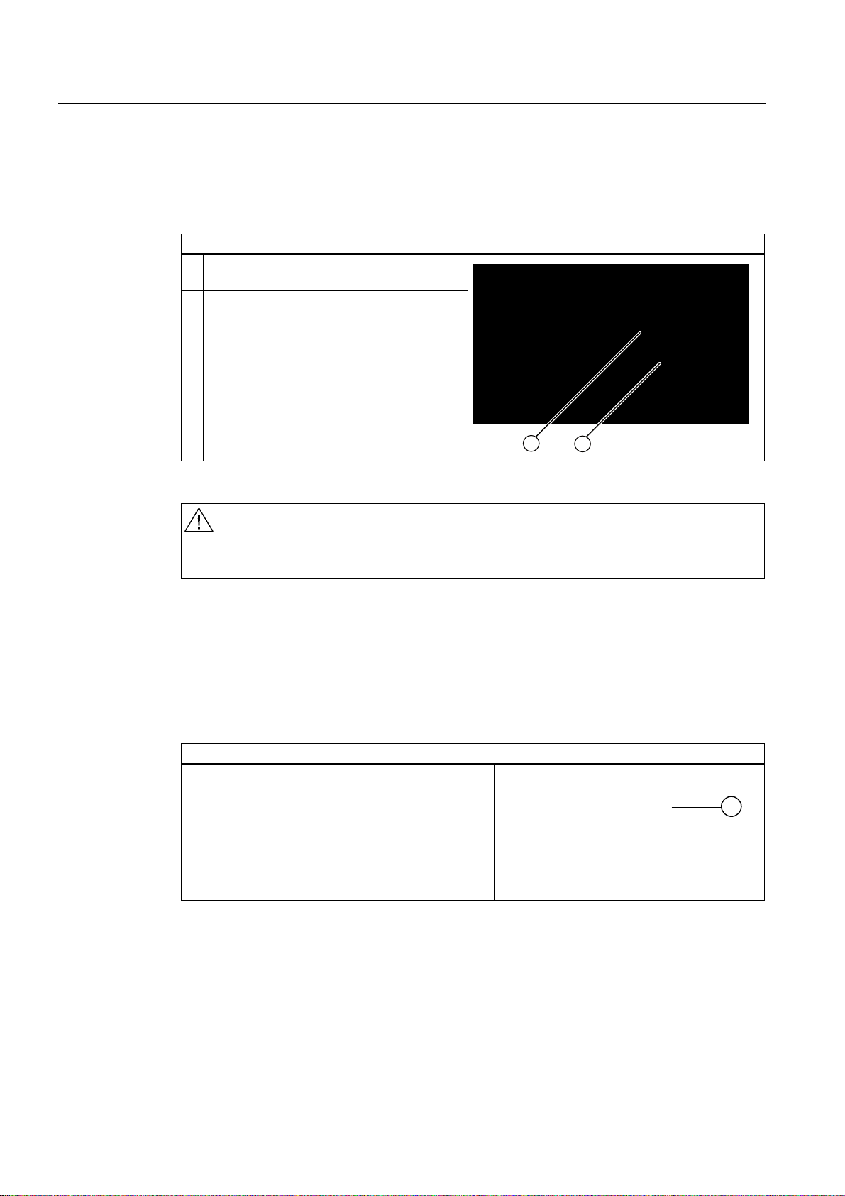
Steps for securing the power plug
1 Remove the lower left mounting screw (2) on
the power supply module.
2 Screw the power plug interlock (1) onto the
power supply module
WARNING
If the power plug is secured with a clamp, the power outlet must be freely accessible to
allow the device to be easily removed from the mains.
6.3 Equipotential bonding
A low-impedance ground connection improves the discharge of interference generated by
external power cables, signal cables or cables for I/O modules to ground.
Equipotential bonding terminal
The equipotential bonding terminal (1) on the device
(large surface, large-area contact) must be
interconnected with the central grounding busbar of
the cabinet or plant in which the PC is to be installed.
The minimum conductor cross-section may not be
less than 5 mm2.
SIMATIC Rack PC 847B
34 Operating Instructions, 06/2008, A5E02203168-01
Page 35
Connecting
6.4 Connecting PROFINET strain relief
6.4 Connecting PROFINET strain relief
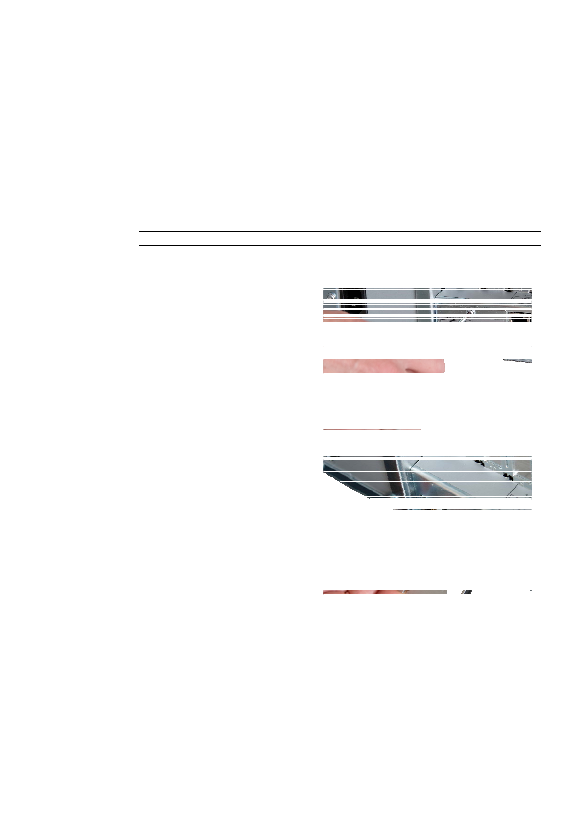
The PROFINET strain relief provided in the package is used to prevent accidental loosening
of the cable from the device. A cable tie (not included in the package) is needed for each
interface.
To fix the PROFINET strain relief, you will need a TORX T10 screwdriver.
Steps for connecting the PROFINET strain relief
1 Remove the PROFINET interface plate.
2 Attach the PROFINET strain relief.
SIMATIC Rack PC 847B
Operating Instructions, 06/2008, A5E02203168-01
35
Page 36

Connecting
6.4 Connecting PROFINET strain relief
Steps for connecting the PROFINET strain relief
3 Attach the cable using the cable tie.
SIMATIC Rack PC 847B
36 Operating Instructions, 06/2008, A5E02203168-01
Page 37

Commissioning
7.1 Requirements for commissioning
● Before you switch on the device, you should verify that all peripheral devices such the
keyboard, mouse, monitor and the power supply are connected.
7.2 Initial Commissioning - Initial Startup
● The operating system of your device is preinstalled on the hard disk.
CAUTION
Risk of damage to the device!
Make sufficient allowances for the device to acquire room temperature before you put it
into use. If condensation has developed on the device wait at least 12 hours before you
switch it on.
7
The Rack PC operating system is automatically set up the first time you switch on the
device. Procedure:
1. Press the on/off button. The green power LED lights up. The PC performs a POST. During
the self-test, this message appears:
Press <F2> to enter SETUP
2. Wait until this message is cleared, then follow the instructions on the screen.
3. Type in the Product Key as required. You find this key on the "Certificate of
Authentication", in the "Product Key" line.
NOTICE
The PC may not be switched off when you run setup.
Do not change the default BIOS settings, otherwise the operating system setup may
become corrupted.
4. Automatic restart
SIMATIC Rack PC 847B
Operating Instructions, 06/2008, A5E02203168-01
37
Page 38

Commissioning
7.3 Windows XP, Vista Security Center
After you have entered all necessary information and after the operating system
setup is completed, the PC is automatically restarted and displays the user interface of the
relevant operating system.
From now on, after you switch on the PC, the user interface of the operating system is
automatically opened when the startup routine is completed.
Switching off the device
Note
On a Windows platform, always shut down the PC by clicking Start > Close.
Press the on/off button behind the front panel door. The green power LED is switched off.
Disconnect the mains connector to isolate the device from mains.
7.3 Windows XP, Vista Security Center
Warning from the Windows Security Center
A warning from the Windows Security Center appears the first time you switch on your
device. The Security Center checks the status of the device in regard to the three important
security aspects listed below. If a problem is detected (an outdated antivirus program, for
example), the Security Center issues a warning and makes recommendations on how you
can better protect the device.
● Firewall: The Windows Firewall adds protection to the device by blocking network or
Internet access to the device by unauthorized users. Windows checks if the device is
protected by a software firewall.
The firewall is enabled by default in the factory state.
● Antivirus software: Antivirus programs add protection to the device by searching for and
eliminating viruses and other security threats. Windows checks if a full-range, up-to-date
antivirus program is running on the device.
No antivirus software is installed in the factory state.
● Automatic updates: Using the Automatic Update feature allows Windows to regularly
search for the latest critical updates for the device and to install them automatically. This
feature is disabled in the factory state.
● Real-time protection (Vista only): Windows Defender displays warnings if spyware or
possibly unwanted software is installed or executed on the computer. You will also
receive a warning if programs attempt to modify important Windows settings.
Configure the Security Center according to your requirements.
SIMATIC Rack PC 847B
38 Operating Instructions, 06/2008, A5E02203168-01
Page 39

Commissioning
7.4 Notes on operation
7.4 Notes on operation
7.4.1 DVD burner
The DVD burner drive is an optional feature. Recording methods supported by the disk drive:
Disc-at-once, Track-at-once, Session-at-once, Packet writing. You can write to CD-R,
CD-RW, DVD+R, DVD-R, DVD-RW, DVD+RW, DVD-RAM and dual-layer media.
Burner software
In order to utilize full functionality of the DVD burner you need to install additional software
(burning software). This software is included on the CD supplied with the device. Insert the
CD in the drive, run setup and follow the instructions on the screen.
NOTICE
When first starting the burner software, no data carriers should be inserted in the drive. This
is because data carriers with errors can interrupt the automatic hard drive recognition. This
makes it impossible to correctly display the possible burner functions.
Notes on burning optical data carriers
CAUTION
Danger of data errors when burning data carriers!
Burning is permissible only in an undisturbed environment, i.e. shock and vibration stress
must be avoided. Because of heavy fluctuation in the quality of CD-Rs, data may be
corrupted in a burning session, even if no error message is initially displayed. The written
data can only be verified by comparing these with the source. To be on the safe side, data
should be verified after every burning session.
SIMATIC Rack PC 847B
Operating Instructions, 06/2008, A5E02203168-01
39
Page 40

Commissioning
7.4 Notes on operation
7.4.2 Removable hard disks
The exchangeable racks support hot-swapping in a RAID1 system.
Replacing a hard disk
CAUTION
Hard drives may only be replaced in an exchangeable rack if the device status display is
off.
Note
The table and information below apply only to the delivery state of the device, that is if no
changes or expansions were made.
How to remove the hard disk:
1. Check which hard disk the RAID controller has reported being faulty (hard disk at channel
1 or 2).
Power LED (1)
Power supply present
HDD activity display (2)
Also note the HDD (7), HDD 1 ALARM (6)
or HDD 2 ALARM (5) status display.
The table below shows the assignment of the exchangeable rack positions in the device to
the RAID system reports:
Assigned
1)
LED
HDD1
ALARM
HDD2
ALARM
1)
If the SIMATIC monitoring software is installed the status LED (5) or (6) on the front panel
is lit if the hard disk has failed.
SIMATIC Rack PC 847B
40 Operating Instructions, 06/2008, A5E02203168-01
RAID BIOS RAID software SATA interface Installation location Enclosure
labeling
Port 0 Device Port 0 SATA0 (3) Exchangeable
rack
Port 2 Device Port 2 SATA2 (4) Exchangeable
rack
1
2
Page 41

Commissioning
7.4 Notes on operation
Note
Always replace the faulty drive with a new drive of the same type and capacity.
Information about the recovery of the RAID system is available in the next section.
1. Set the key switch to the "OPEN" position.
2. Lift up the folding handle of the hard disk cartridge.
3. Pull the hard disk cartridge out.
Notes on operation
NOTICE
Always interlock the hard disk cartridge with the exchangeable rack in order to ensure
reliable operation of the device.
Exchangeable rack lock (1)
SIMATIC Rack PC 847B
Operating Instructions, 06/2008, A5E02203168-01
41
Page 42

Commissioning
7.4 Notes on operation
7.4.3 2HDD system (optional)
When the device ships, the second hard disk is connected to SATA port 2. This hard disk
drive is not set up. This gives you the option of backing up your data to this hard disk. For
information on hard disk capacities, refer to your order documentation.
Booting from the slave hard disk
In order to allow booting from the second hard disk, you need to configure it as the primary
boot device. Make the following settings in your BIOS Setup:
Select Boot > Hard Drive > <Disk name> e.g. STxxxxxxxxx- SATA2, then press the "+" key
to move it up in the boot order.
NOTICE
The drive letters for the partitions on both drives are assigned by the operating system
used. You can change these in the Control Panel as required.
SIMATIC Rack PC 847B
42 Operating Instructions, 06/2008, A5E02203168-01
Page 43

Commissioning
7.4 Notes on operation
7.4.4 RAID system
This is a RAID1 system configuration (mirroring with two hard disks). This configuration
enhances system availability as the system is able to continue operation if a hard drive fails,
or if there is a cable problem at a channel.
Note
You can find information regarding Intel RAID controllers in the RAID documentation on the
included "Documentation and Drivers" CD in the Drivers\RAID\Intel directory.
Intel(R) Matrix Storage Manager option ROM v5.6.2.1002 ICH7R wRAID5
Copyright(C) 2003-06 Intel Corporation. All Rights Reserved.
RAID Volumes:
ID Strip Size Bootable Level Status
Name
0 N/A 149.1GB Yes RAID1(Mirror) RebuildVolume0
Physical Disks:
Port Size Serial # Type/Status(Vol ID) Drive Model
0 149.1GB5RA01YJT Member Disk(0) ST3160815AS
2 149.1GB5RA01YHY Member Disk(0) ST3160815AS
Press
<CTRL-I>
Figure 7-1 Example
to enter Configuration Utility...
SIMATIC Rack PC 847B
Operating Instructions, 06/2008, A5E02203168-01
43
Page 44

Commissioning
7.4 Notes on operation
RAID system management functions
The pre-installed RAID system software offers enhanced functionality for RAID system
operation and management. Start the SW by selecting the "Start > Programs > Intel Matrix
Storage Manager command.
Figure 7-2 Example
The "View -> Advanced Mode" command returns details of the RAID volumes.
The command "View -> System Report" can be used to create a report with details of the
RAID volumes.
NOTICE
The RAID status entries are returned by default in the Windows event view and in the log
file of the program.
A hard drive can be synchronized at operating system level if a fault is detected. It may take
up to several hours to synchronize a new hard disk in the background, depending on the its
size and on system load.
The redundant system state RAID Level 1 is only recovered if synchronization has been
successfully completed.
SIMATIC Rack PC 847B
44 Operating Instructions, 06/2008, A5E02203168-01
Page 45

Commissioning
7.4 Notes on operation
Comments about faults
NOTICE
Input delay
System load may briefly increase due to synchronization when a hard disk has failed,
depending on processor load and current hard disk activity.
Execution of keyboard and touch screen commands may be briefly delayed in extreme
situations.
Replacing a faulty drive in a RAID array
Replace faulty RAID drives with a new drive in order to recover secure RAID1 state. The
RAID software reports the faulty drive and returns details of the operable hard drive.
The functioning hard drive is indicated in BIOS by its port number, or by the RAID software
by its device port number.
Figure 7-3 Example
SIMATIC Rack PC 847B
Operating Instructions, 06/2008, A5E02203168-01
45
Page 46
Commissioning
7.4 Notes on operation
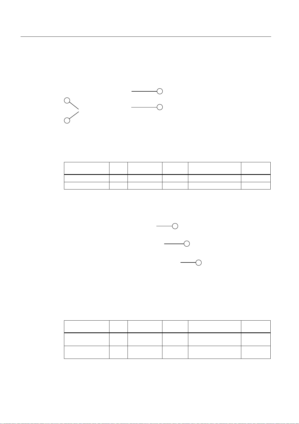
The functioning drive can be located using the following pictures and tables.
The table and information below apply only to the delivery state of the device, that is if no
changes or expansions were made.
Figure 7-4 Drives in the exchangeable rack
Assigned LED 1) RAID
BIOS
HDD1 ALARM (6) Port 0 Device Port 0 SATA0 Exchangeable rack (1) 1
HDD2 ALARM (5) Port 2 Device Port 2 SATA2 Exchangeable rack (2) 2
RAID software SATA
interface
Installation location Enclosure
labeling
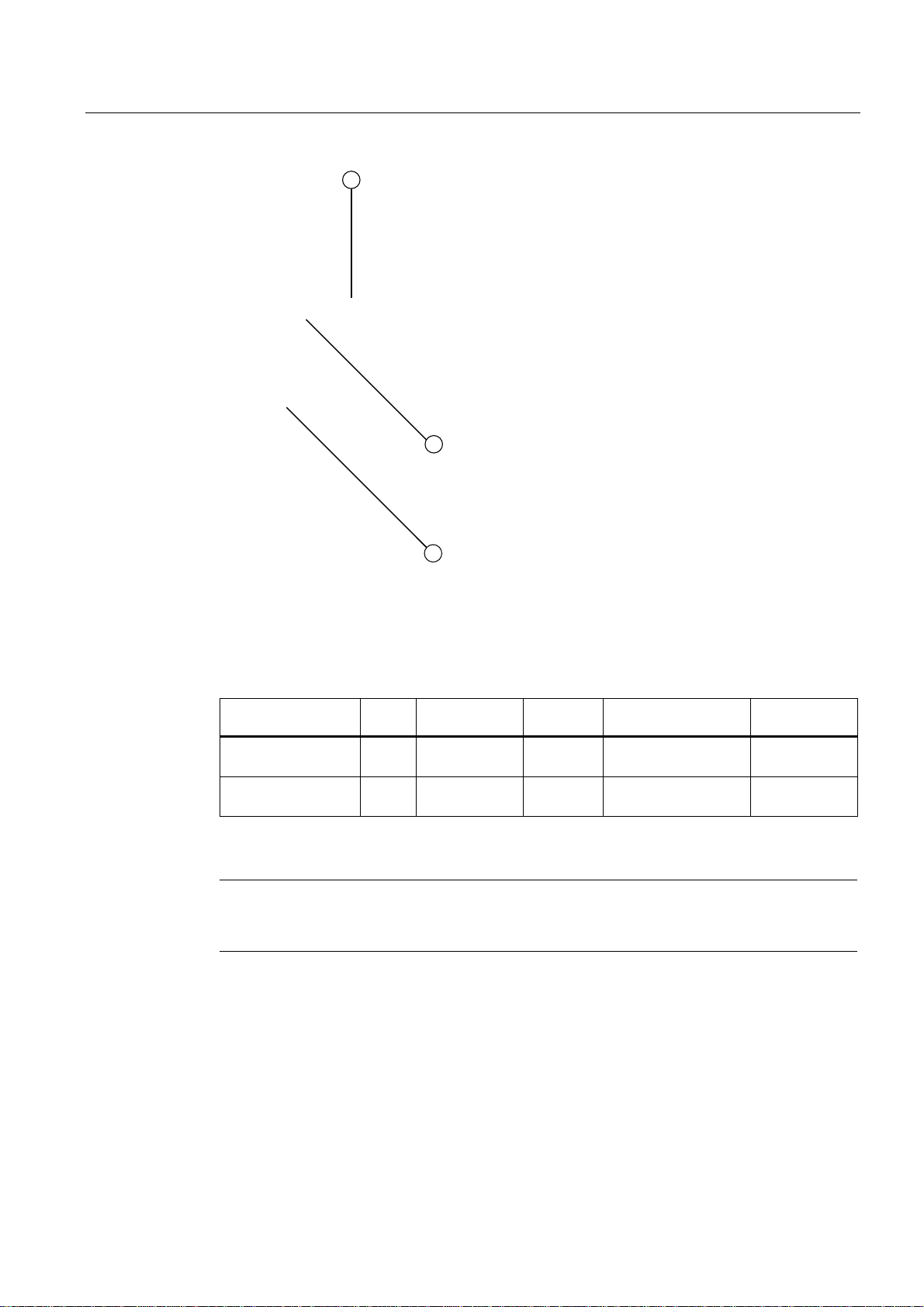
Figure 7-5 Drives in the internal drive bay (fixed)
Assigned LED 1) RAID
BIOS
HDD1 ALARM Port 0 Device Port 0 SATA0 Side panel (3) drive (1)
HDD2 ALARM Port 2 Device Port 2 SATA2 Side panel (3)
RAID software SATA
interface
Installation location Enclosure
labeling
1
drive (2)
2
SIMATIC Rack PC 847B
46 Operating Instructions, 06/2008, A5E02203168-01
Page 47
Commissioning
7.4 Notes on operation
Figure 7-6 Drives in the internal drive bay (with vibration damping)
Assigned LED 1 RAID
BIOS
HDD1 ALARM Port 0 Device Port 0 SATA0 Drive bay (4) drive (1)
HDD2 ALARM Port 2 Device Port 2 SATA2 Drive bay (4) drive (2)
1)
The LED (5) or (6) of the status displays on the front panel is lit if the HDD fails, provided
the SIMATIC monitoring software is installed.
Note
The table and information below apply only to the delivery state of the device, that is if no
changes or expansions were made.
RAID software SATA
interface
Installation location Enclosure
labeling
1
2
Always replace the faulty drive with a new one of the same type and capacity.
SIMATIC Rack PC 847B
Operating Instructions, 06/2008, A5E02203168-01
47
Page 48

Commissioning
7.4 Notes on operation
NOTICE
Drives in exchangeable racks can be hot-swapped without shutting down the device.
Devices without exchangeable rack may only be replaced in shutdown state.
The new HDD can be integrated into the RAID system at operating system level by means
of the RAID software. Synchronization may take several hours, depending on system load.
Both HDD alarm displays of the front panel flash during synchronization. This is not
possible at BIOS level.
Points to note if the hard disk is replaced when the computer is turned off
Only a hard disk that was active and functioning correctly when you booted can later be
included in the RAID array.
To be able to boot from the RAID system, you must place this first in the list of bootable
sources in the BIOS "Boot" setup menu. Otherwise the system will boot from the hard disk
you have just installed and the message "Operating system not found" will be displayed.
SIMATIC Rack PC 847B
48 Operating Instructions, 06/2008, A5E02203168-01
Page 49

Commissioning
7.4 Notes on operation
Integrating a new hard drive
Select the "Rescan for Plug and Play Devices" command to find and indicate the new HDD.
You can also choose to reboot the device. In this case, the RAID software automatically
integrates the new HDD and synchronizes the RAID system.
Figure 7-7 Example
If you have shut down and restarted the system without installing a functioning new hard
disk, "unused" will be displayed for the corresponding SATA port. In this case, you will need
to shut down the system again and boot with the functioning hard disk. The new hard disk is
then assigned to a SATA port and can be included in the RAID array.
SIMATIC Rack PC 847B
Operating Instructions, 06/2008, A5E02203168-01
49
Page 50

Commissioning
7.4 Notes on operation
The "Rebuild to this Hard drive" command initiates synchronization of the RAID1 system.
Figure 7-8 Example
SIMATIC Rack PC 847B
50 Operating Instructions, 06/2008, A5E02203168-01
Page 51
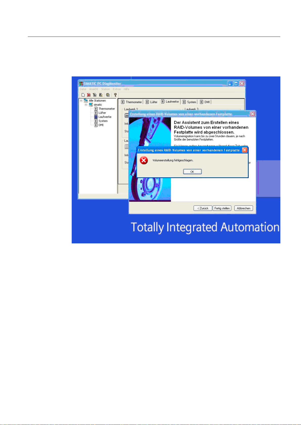
Commissioning
7.4 Notes on operation
Notes on RAID configuration with installed SIMATIC PC DiagMonitor software
When creating a RAID-system where SIMATIC PC DiagMonitor software is being used, the
Intel Matrix Storage Console may abort the process with the following error message:
Solution:
Before performing a RAID commissioning, the SIMATIC PC DiagMonitor should be
deactivated. Subsequently, it can be reactivated.
Measures:
If the DiagMonitor Management Station is in operation on your device:
● Close all applications, including the Management Station.
● Afterwards, stop the DiagMonitor SNMP Agent (SOL Agent). In order to do so, select
Start > Run and enter cmd in the Open field.
● Then enter Net stop snmp and confirm with the Enter key.
If your device is remotely monitored with SIMATIC PC DiagMonitor:
In this case you need only stop the DiagMonitor SNMP Agent (SOL Agent).
● In order to do so, select Start > Run and enter cmd in the Open field.
● Then enter Net stop snmp and confirm with the Enter key.
SIMATIC Rack PC 847B
Operating Instructions, 06/2008, A5E02203168-01
51
Page 52

Commissioning
7.4 Notes on operation
NOTICE
If you do not adhere to the procedure described above, a correct RAID configuration
cannot be guaranteed.
SIMATIC Rack PC 847B
52 Operating Instructions, 06/2008, A5E02203168-01
Page 53

Integration
8.1 Integration
Options of integration in existing or planned system environments/networks:
Ethernet
Wake on LAN and Remote Boot are supported.
The integrated Ethernet interfaces (10/100/1000 Mbps) can also be used for communication
and data exchange with programmable controllers such as SIMATIC S7.
This functionality requires the "SOFTNET S7" software package.
PROFIBUS/MPI
The optional electrically isolated PROFIBUS interface (12 Mbps) can be used to interconnect
distributed field devices or for coupling to SIMATIC S7.
8
The "SOFTNET for PROFIBUS" software package is required for coupling to S7 automation
systems.
PROFINET
CP 1616 onboard allows you to connect industrial PCs to Industrial Ethernet. Only one CP
1616 module can be installed on a PG/PC. You can find detailed information in the next
section or in the section "Detailed Description > CP 1616 onboard".
Device driver CP 16xx.sys
The device driver allows you to use the Windows network protocol for the optionally available
"CP 1616 onboard" Ethernet PROFINET controller on SIMATIC PCs. The PROFINET
interface will act like a 100 MBit Ethernet interface with a MAC address when you use this
driver. The three RJ45 sockets are connected to each other via switch.
The drivers and documentation can be found in the user manual on the supplied
Documentation and Drivers CD.
SIMATIC Rack PC 847B
Operating Instructions, 06/2008, A5E02203168-01
53
Page 54

Integration
8.1 Integration
PROFINET IO application
You can use the "Development Kit DK-16xx PN IO" to create, operate and configure
PROFINET IO applications. It must be installed in addition to the CP 16xx.sys device driver.
This kit and the documentation are available for free of charge at the following Internet
address:
http://www.automation.siemens.com/net/html_00/produkte/040_cp_1616_devlopkit.htm
SIMATIC NET
You can create, operate and configure SIMATIC installations using this software package.
You will find this information on the SIMATIC NET Manual Collection CD. The software
package and the documentation are not parts of the development package.
Additional information
You can find additional information in the catalog and the Siemens online ordering system.
Internet address: http://mall.automation.siemens.com
SIMATIC Rack PC 847B
54 Operating Instructions, 06/2008, A5E02203168-01
Page 55

Integration
8.2 PROFINET
8.2 PROFINET
CP 1616 onboard
The basic characteristics of the PCS 1616 onboard are:
● Optimized for PROFINET IO
● With Ethernet realtime ASIC ERTEC 400
● Three RJ45 sockets for connecting terminal devices or addition network components
● Integrated 3-port real-time switch
CAUTION
Only one CP 1616 can be installed in a PG/PC. If you want to use an additional CP
1616 module, the "CP 1616 onboard" option must be disabled in the BIOS Setup.
Additional documentation on PROFINET
● Automatic hardware detection
Get an overview of the information available on the topic of PROFINET.
Document designation What is contained in this document?
This documentation is not included in the product package:
Getting Started
PROFINET IO Getting Started: Manual
Collection
Manual
PROFINET System Description
Manual
From PROFIBUS DP to PROFINET IO
Readme file for CP 1616/CP 1604 and DK16xx PN IO
Configuration Manual
Commissioning PC Stations
Manual
SIMATIC NET Industrial Communication
with PG/PC: Volume 1 - Basics
SIMATIC NET Industrial Communication
with PG/PC: Volume 2 - Interfaces
S7 CPs for Industrial Ethernet
Configuring and Commissioning
The documents use concrete examples to provide
step-by-step instructions on how to commission a fully
functional application.
This gives you the basic knowledge about the
PROFINET IO topics:
Network components, data exchange and
communication, PROFINET IO, component-based
automation, application example of PROFINET IO and
component-based automation.
Read this document if you want to convert an installed
PROFIBUS system to a PROFINET system.
This provides the latest information about the
SIMATIC NET products CP 1616/CP 1604, CP 1616
onboard, the developer kit.
This provides you will all the information necessary for
commissioning and configuring a PC as a PROFINET
IO controller or IO device.
This manual introduces you to industrial
communication and explains the available
communication protocols. It also describes the OPC
interface as an alternative to the IO-based user
programming interface.
This provides the following support:
- For commissioning S7 stations
- For establishing effective communication
SIMATIC Rack PC 847B
Operating Instructions, 06/2008, A5E02203168-01
55
Page 56

Integration
8.2 PROFINET
Document designation What is contained in this document?
Manual
SIMATIC NET - Twisted Pair and FiberOptic Networks
This documentation is part of the supplied Documentation and Drivers CD:
Operating instructions
CP 1616/CP 1604/CP 1616 onboard
Installation guide
Device Driver CP16xx.sys
Configure and build your Industrial Ethernet networks
based on this document.
This provides you with all information required for
operation.
Read this guide if you want to install the NDIS device
driver, CP16xx.sys.
Further information
You can find the information on specific products in the Internet at the address:
http://www.siemens.de/simatic-net
SIMATIC Rack PC 847B
56 Operating Instructions, 06/2008, A5E02203168-01
Page 57

Functions
9.1 Overview of the monitoring functions
Functions implemented:
● Temperature monitoring and over/under-temperature display
● Watchdog
● Fan monitoring
● RAID alarm display
Messages of the monitoring modules can be transferred to applications.
The SOM software (Safecard On Motherboard) and DiagMonitor software on CD (optional)
can be used to handle this functionality.
The DiagMonitor software CD contains the monitoring software, the software for the stations
to be monitored, and a library for creating user-specific applications.
The descriptions of drivers and of the SOM program are available on the CD "Documentation
and Drivers" under Drivers & Updates\<device>\...
9
9.2 Temperature monitoring/display
Temperature monitoring
The temperature is recorded using four temperature sensors which are installed at critical
locations of the device. One sensor monitors the processor temperature, the second the
temperature in the area near the processor module, and the third or fourth the temperature
underneath the bus module.
The flashing Temp LED indicates that the device is being operated at its limits. The following
fault reactions are triggered if one of the temperature values exceeds the set temperature
threshold:
Reaction Option
The Temp LED changes to red None
Device cooling fan switches to maximum speed (the power unit
controls its own fan)
SIMATIC monitoring software is activated None
SIMATIC Rack PC 847B
Operating Instructions, 06/2008, A5E02203168-01
None
57
Page 58
Functions
9.3 Watchdog (WD)
The temperature error is retained in memory until temperatures have fallen below the
thresholds and are reset by one of the following measures:
● Check whether the ambient temperature limit has been exceeded, or whether the filter is
soiled.
● Acknowledgment of the error message by the monitoring software
● Restart of the device
9.3 Watchdog (WD)
Function
The watchdog monitors program execution and reports a program crash to the user by
means of various reactions.
After POWER ON of the PC, or after a HW RESET (cold restart), the watchdog is in idle
state, that is, a reaction of the WD is not triggered and the Watchdog LED is switched off.
The Watchdog LED is lit green when the watchdog is enabled (by means of the driver, SOM
program or DiagMonitor software.)
WD reactions
If the WD is not triggered again within the set time (by the driver or SOM program), the
following reactions are initiated:
Reaction Option
Watchdog LED changeover from green to red None
Trigger a PC reset Configurable
SIMATIC monitoring software is activated None
WD monitoring times (TWD)
The monitoring times can be set in increments of one second within a range from 3 to 255
seconds.
Note
The watchdog is retriggered if the monitoring time is changed at the active watchdog (that is
while the watchdog is running)!
SIMATIC Rack PC 847B
58 Operating Instructions, 06/2008, A5E02203168-01
Page 59
Functions
9.4 Fan monitoring
9.4 Fan monitoring
Operation of the front / processor / power unit fans is monitored. The following reactions are
triggered when a fan fails:
Reaction Option
The fan LED switches to red None
SIMATIC monitoring software is activated None
The fan fault is retained in memory until the cause of the fan failure has been rectified and
the error is reset by taking one of the following measures:
● Acknowledgment of the error message by the SOM program or DiagMonitor software.
● Restart of the device.
9.5 RAID monitoring
In conjunction with the SIMATIC monitoring software and in addition to the RAID software,
the status of the RAID system is shown on the HDD1 alarm and HDD2 alarm front LEDs. For
detailed information on the RAID system and on the operation of the RAID software, refer to
the RAID section.
Reaction Description Option
HDD1 alarm
HDD2 alarm
Off RAID system is ready for operation. SIMATIC
One is red Drive 1 or Drive 2 has failed.
Both are red RAID system is not ready for operation.
Both flash RAID system is currently being synchronized.
None
software is not active.
Affected drive must be determined with the
help of the RAID software.
SIMATIC Rack PC 847B
Operating Instructions, 06/2008, A5E02203168-01
59
Page 60
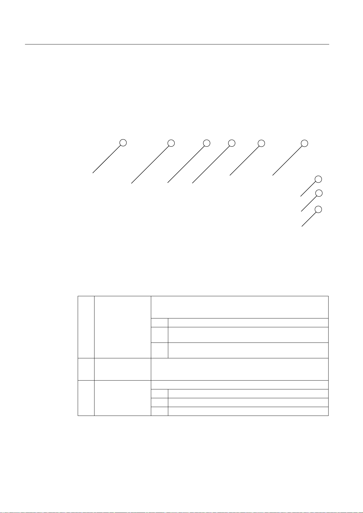
Functions
9.6 Safecard on Motherboard (SOM)
9.6 Safecard on Motherboard (SOM)
This application is used to monitor PC hardware (temperature, watchdog and fans) and to
display the current measured values. You can also configure the temperature and fan
monitoring functions, and the watchdog function.
Your device is equipped with three temperature sensors which are automatically detected by
the application.
FED
D
E
F
Figure 9-1 Safecard On Motherboard
(1) Temperature range
(2) Watchdog range Here, you can configure the watchdog function in your monitoring
(3) Fan area
Displays the current temperature and limit values. You can toggle the
temperature display mode to indicate either the current temperature, or
the min./max. values measured since the start of the application.
(1a) Internal processor temperature
(1b) Internal device temperature beneath the power supply:
high threshold can be set from 30°C to 80°C
(1c) Internal device temperature beneath the bus module:
high threshold can be set from 30°C to 80°C
application. You can specify the watchdog time, activate a PC reset
and activate / deactivate the watchdog.
You can read the current fan speed in this area.
(3a) Speed of the front fan
(3b) Speed of the HDD fan
(3c) Speed of the power unit fan
The description of the SOM software and the drivers for Windows are available on the
"Documentation and Drivers" DVD in Drivers & Updates\<device>\...
From the CD, run Install.bat and follow the instructions on your screen.
SIMATIC Rack PC 847B
60 Operating Instructions, 06/2008, A5E02203168-01
Page 61
Expansions and programming
10.1 Open the device
Tools
CAUTION
Only authorized technical personnel are allowed to carry out any work on the open device.
You may only install memory modules and expansion cards to expand the hardware within
the warranty period.
CAUTION
The device contains electronic components which may be destroyed by electrostatic
charge.
Take appropriate precautionary measures before you open the device. Refer to the ESD
directives on handling components which are sensitive to electrostatic charge.
You can install all device components using TORX T10 and T20 drivers and a 4.5-mm
hexagonal wrench (for the interface interlock on the rear panel.)
10
Preparation
Liability disclaimer
SIMATIC Rack PC 847B
Operating Instructions, 06/2008, A5E02203168-01
Disconnect the device from the mains.
WARNING
Unauthorized opening of device without previously disconnecting power may result in
substantial damage to equipment and/or danger to the user.
All technical data and approvals apply only to expansion units which are released by
SIEMENS.
No liability can be accepted for impairment of functions caused by the use of third-party
devices or components.
Observe the installation instructions for the components. UL approval of the device only
applies when the UL-approved components are used according to their "Conditions of
Acceptability".
61
Page 62

Expansions and programming
10.1 Open the device
Open the device
How to open the device
1 Open the front door
2 Remove the lid screw (Torx T10)
3 Slide the lid towards the rear and
remove it
SIMATIC Rack PC 847B
62 Operating Instructions, 06/2008, A5E02203168-01
Page 63
Expansions and programming
10.2 Memory expansion
10.2 Memory expansion
10.2.1 Installing memory modules
Memory expansion options
The motherboard features two memory slots under the bus module. You can install 667 MHz
SO-DIMM DDR2 memory modules, type PC2-5300, unbuffered, no ECC. This allows you to
expand Rack PC memory up to 4 GB, of which you can use approx. 3.2 GB for the operating
system and applications. You can install one or two modules.
Combination Slot X19 (bottom) Slot X20 (top) Maximum
expansion
1 256/512 MB / 1 GB / 2 GB 2 GB
2 256/512 MB / 1 GB / 2 GB 256/512 MB / 1 GB / 2 GB 4 GB
Preparation
Note
The modules can be inserted into any slot. Memory is operated in dual-channel mode if two
modules are installed.
Disconnect the device from mains and unplug all cables.
CAUTION
The electronic components on the PCBs are highly sensitive to electrostatic discharge.
Always take appropriate precautionary measures when handling these components. Refer
to the ESD directives on handling electrostatic sensitive components.
SIMATIC Rack PC 847B
Operating Instructions, 06/2008, A5E02203168-01
63
Page 64
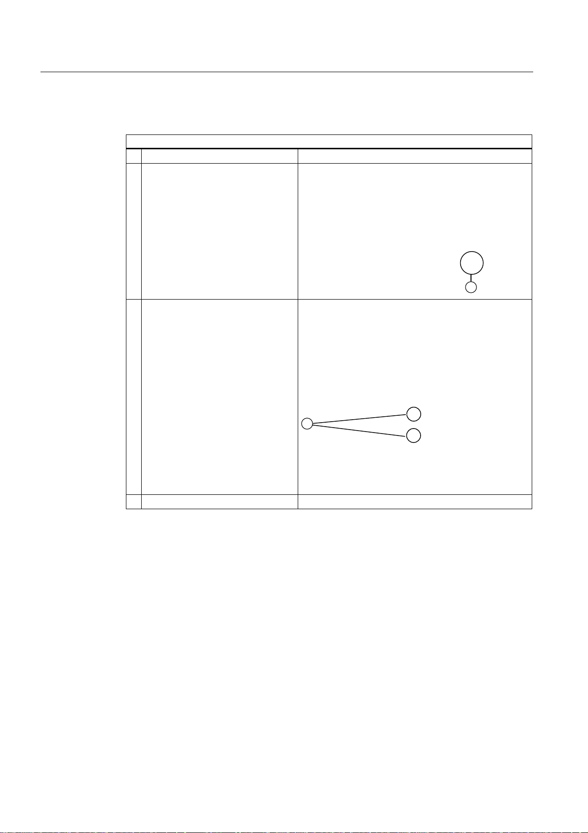
Expansions and programming
10.2 Memory expansion
Installing a memory module
How to install a memory module
1 Open the device.
2 Note the recess (1) (reversal
protection) on the connector side of
the RAM module.
3 Push the module carefully into the
slot until the latches engage.
4 Close the device.
SIMATIC Rack PC 847B
64 Operating Instructions, 06/2008, A5E02203168-01
Page 65
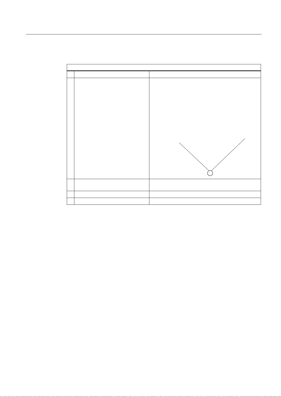
Expansions and programming
10.2 Memory expansion
Removing a memory module
How to remove a memory module
1 Open the device.
2 Open the left and right latches (1).
Start by opening the latches of the top
memory module.
3 Pull the memory module out of the
slot.
4 Remove the bottom memory module.
5 Close the device.
Display of the current memory configuration
The new memory configuration is detected automatically. The allocation of the ”base
memory and extended memory” is automatically displayed when you switch on the device.
SIMATIC Rack PC 847B
Operating Instructions, 06/2008, A5E02203168-01
65
Page 66

Expansions and programming
10.3 Installing expansion cards
10.3 Installing expansion cards
10.3.1 Notes on the modules
Notes on module specifications
The device is designed for use with modules to PCI specifications 2.3 or 1.0a. The module
supports operation of 5 V and 3.3 V PCI modules. Compliance with the defined mechanical
defaults is imperative. Failure to comply with these defaults can result in contact problems,
malfunctions and assembly difficulties. The permissible module contour dimensions are
specified in the dimension drawings section.
Note about long PCI, PCIe modules
Long PCI / PCIe modules must be fitted with an extender for insertion into the guide rails
(should be supplied with the long PCI PCIe board.)
Note on PCI-Express x16 modules
The modules in the PCIe x16 slot should not occupy more than one slot.
Note on PROFINET expansion modules
The "CP 1616 onboard" option must be disabled in the BIOS for devices with CP 1616
onboard, before a PROFINET module (such as a CP 1616) can be installed in the system.
SIMATIC Rack PC 847B
66 Operating Instructions, 06/2008, A5E02203168-01
Page 67
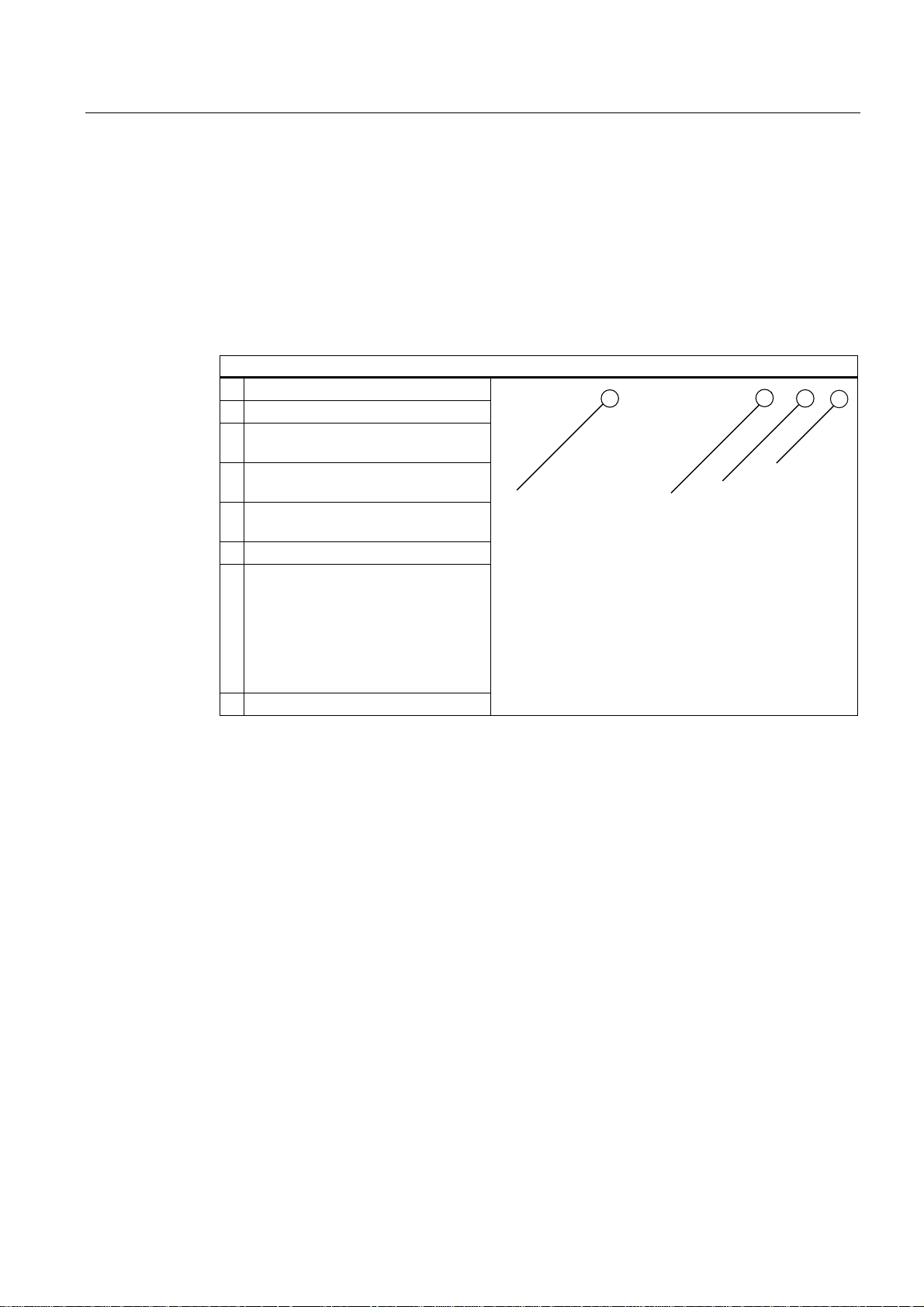
Expansions and programming
10.3 Installing expansion cards
10.3.2 Installing an expansion module
Preparation
Disconnect the device from mains.
Installing expansion modules
How to install an expansion module (PCI / PCIe format):
1 Open the device
2 Remove the module retainer (3)
3 Remove the relevant steel slot cover
(1).
4 Insert the expansion module (2) into
the relevant slot.
5 Screw-tighten the steel slot cover (1)
of the expansion module.
6 Reinstall the module retainer (3).
7 Release the free module retainer (4),
fit it on the expansion module and
tighten the screws.
With short expansion modules, you
can remove the locking screw from
the retainer and screw it into the hole
on the opposite side.
8 Close the device
Notes on the allocation of resources
Only two exclusive interrupts are available for PCI /PCIe modules due to the large functional
scope of the motherboard. If the new expansion modules require additional exclusive
resources, you must disable certain motherboard functions. For information on allocated
resources, refer to the system resources section. Information on disabling motherboard
functions is available in the BIOS Setup menu. Information on the assignment of the PCI IRQ
Line to the PCI slots is found in the "Advanced menu" or "Bus board" section.
The device supports graphics modules with expansion ROM of up to 48 K.
SIMATIC Rack PC 847B
Operating Instructions, 06/2008, A5E02203168-01
67
Page 68
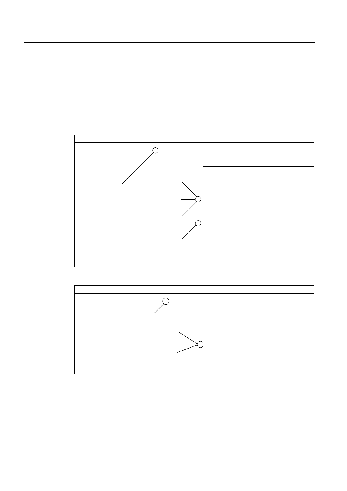
Expansions and programming
10.4 Installing drives
10.4 Installing drives
10.4.1 Options of installing disk drives
In the front drive bay Item Description
(1) Front drive bay
(2) 5.25" drive bay for DVD drives or
exchangeable racks.
(3) Floppy Disk 3.5" (FD)
In the rear drive bay (with vibration damping) Item Description
(1) Rear drive bay
(2) Two bays for hard disk drives (with
shock and vibration damping)
SIMATIC Rack PC 847B
68 Operating Instructions, 06/2008, A5E02203168-01
Page 69
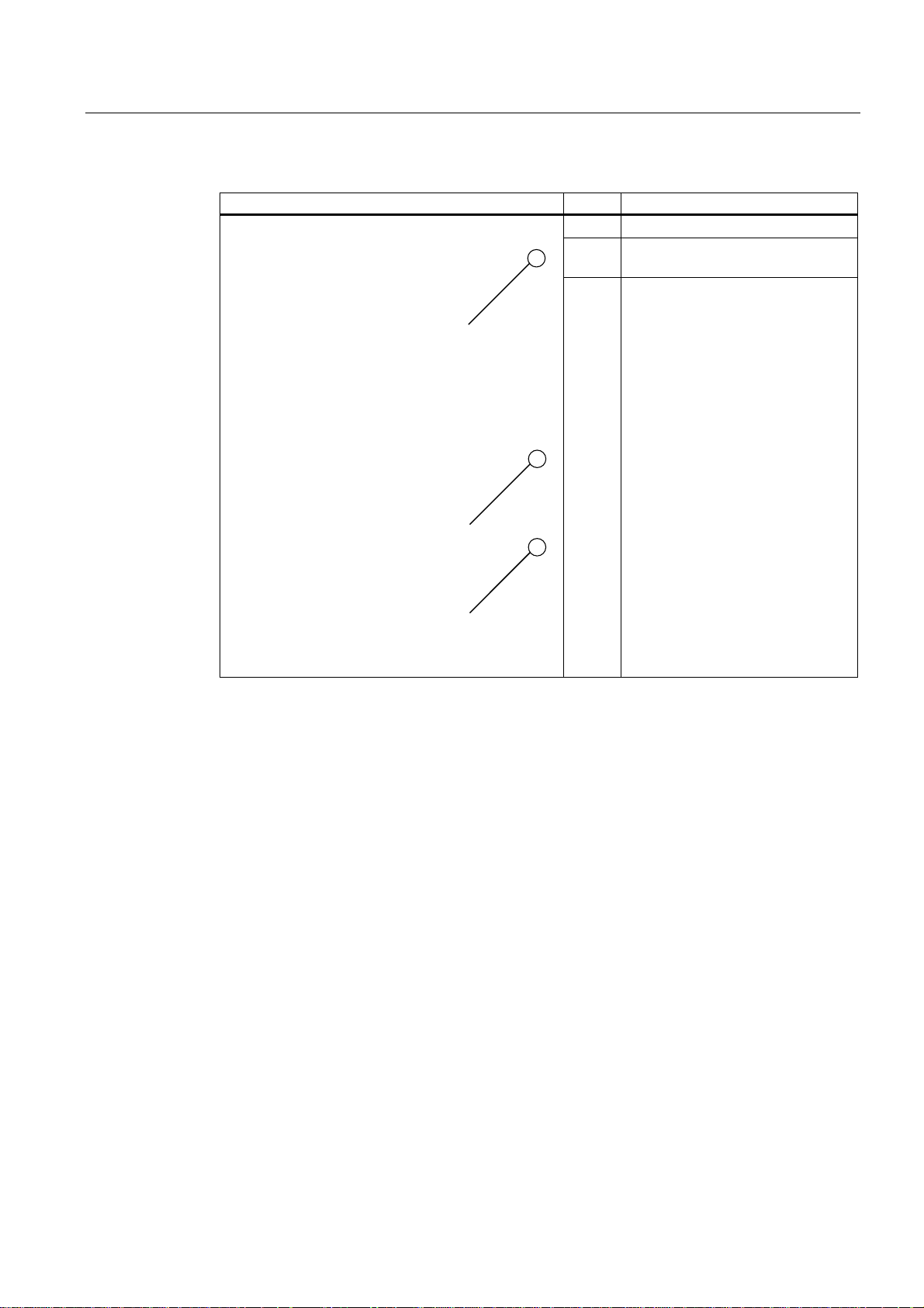
Expansions and programming
10.4 Installing drives
Internal drive bay (fixed) Item Description
(1) HDD
(2) Second drive bay for 3.5" hard disk
(3) Internal drive bay (fixed) It is not
drives
required to remove the drive bay for
hard disk installation or removal.
SIMATIC Rack PC 847B
Operating Instructions, 06/2008, A5E02203168-01
69
Page 70
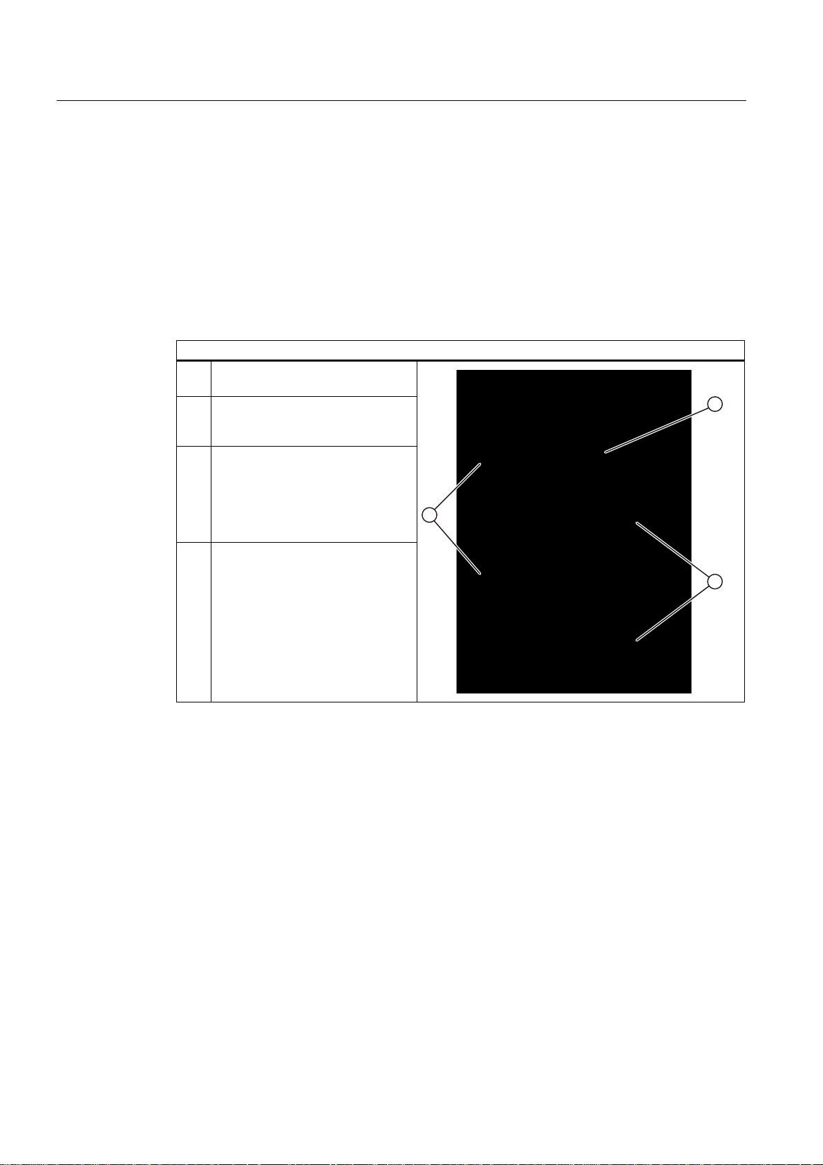
Expansions and programming
10.4 Installing drives
10.4.2 Installing and removing disk drives in the front drive bay
Preparations
1. Unplug the device from mains and disconnect all cables.
2. Open the device
Remove the front drive bay
How to remove the front drive bay
1 Remove the mounting screws (2)
and (3).
2 Disconnect the power and data
cables from the installed disk
drives.
3 Lift up drive bay (1) by approx.
1 cm in the direction of the power
supply in order to access the
connecting cables of the floppy
disk drive.
Disconnect these cables
4 Remove the drive bay from the
device
SIMATIC Rack PC 847B
70 Operating Instructions, 06/2008, A5E02203168-01
Page 71
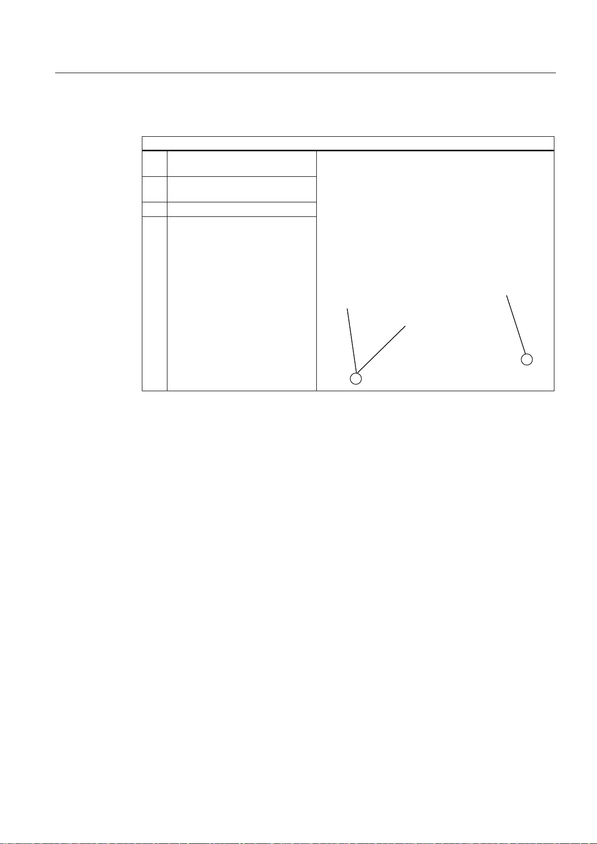
Expansions and programming
10.4 Installing drives
Installing drives or exchangeable racks
How to install a drive
1 Slide the drive (1) into the bay from
the front
2 Secure the drive in the drive bay
using four screws (2)
3 Reinstall the drive bay
4 Connect the power and data cables
to the disk drive.
SIMATIC Rack PC 847B
Operating Instructions, 06/2008, A5E02203168-01
71
Page 72
Expansions and programming
10.4 Installing drives
10.4.3 Installing and removing drives in the front drive bay
Preparations
1. Unplug the device from mains and disconnect all cables.
2. Open the device
Removing internal drive bays
How to remove the internal drive bay (with vibration damping)
1 Remove the module retainer
2 Remove the four screws (1)
3 Disconnect the power and data
cables from the installed drives
4 Remove the drive bay from the
enclosure
SIMATIC Rack PC 847B
72 Operating Instructions, 06/2008, A5E02203168-01
Page 73

Expansions and programming
10.4 Installing drives
Installing a drive
How to install a drive
1 Slide the drive into the bay from the
front
2 Secure the drive in the drive bay
using four screws
3 Reinstall the drive bay
4 Connect the power and data cables
to the disk drive.
SIMATIC Rack PC 847B
Operating Instructions, 06/2008, A5E02203168-01
73
Page 74
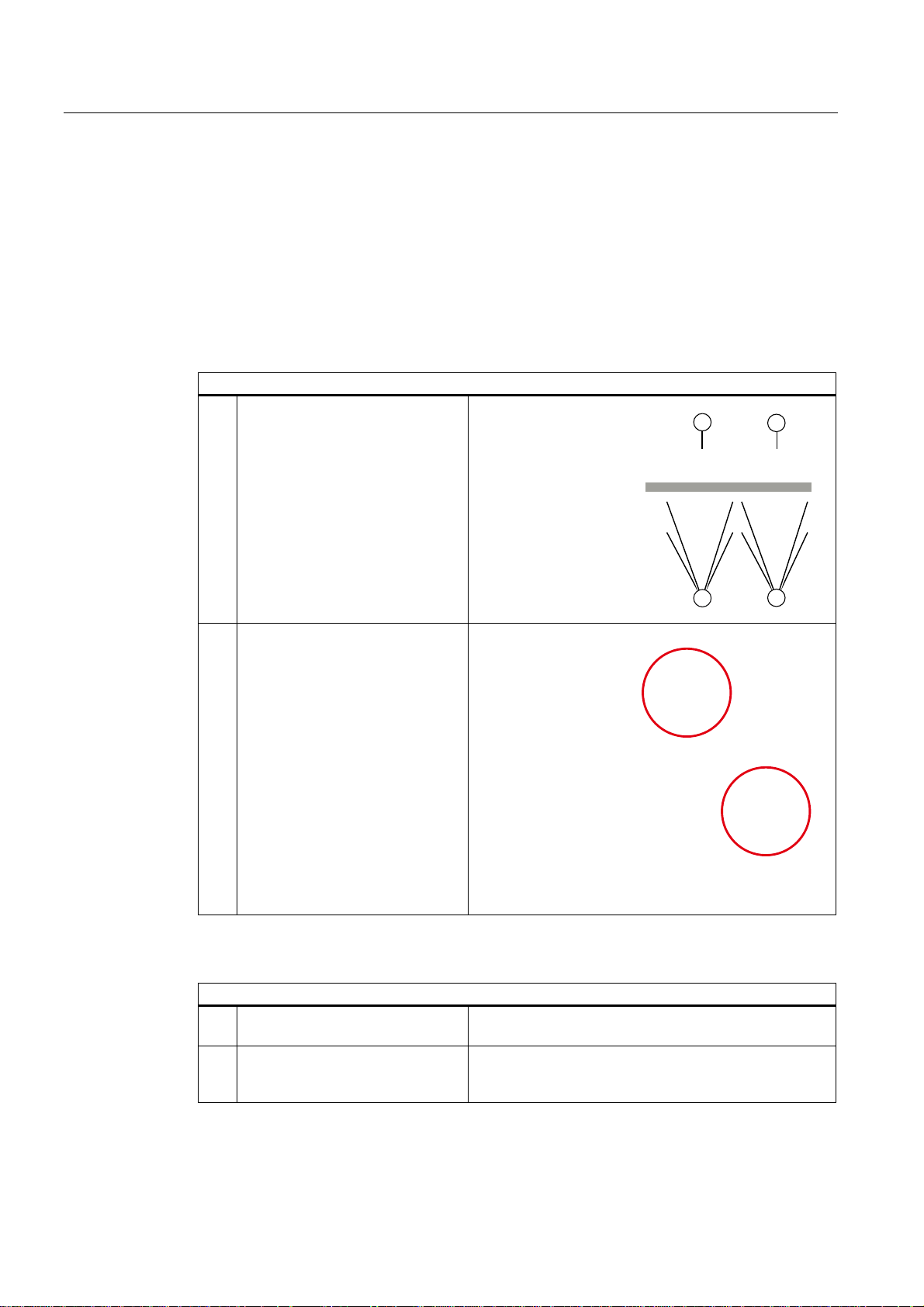
Expansions and programming
10.4 Installing drives
10.4.4 Installing / removing hard disk drives in the fixed hard disk rack
Preparations
1. Unplug the device from mains and disconnect all cables.
2. Open the device
Installing a drive
How to install a drive
1 Place the drive (1) or (2) onto the
drive tray and secure it using four
screws (3) or (4).
Removing drives
2 Connect the power and data cables
to the disk drive.
How to remove a drive
1 Disconnect the power and data
cables from the drive.
2 Remove the four screws (3) or (4)
and take the drive out of the
housing.
SIMATIC Rack PC 847B
74 Operating Instructions, 06/2008, A5E02203168-01
Page 75
Maintenance and service
11.1 Removing and installing hardware components
11.1.1 Repairs
Repairing components
Only authorized technical personnel are allowed to repair device components.
WARNING
Unauthorized opening and improper repairs may lead to material damage and hazards to
users.
● Always disconnect the power connector before you open the device.
● Install only system expansions which are designed for this computer. Installation of other
expansions may damage the system or violate safety requirements and RF interference
suppression regulations. Contact Technical Support or your local sales department to find
out which system expansions are suitable for installation.
11
If you install or exchange system expansions and damage your device, the warranty
Disclaimer of liability
Tools
SIMATIC Rack PC 847B
Operating Instructions, 06/2008, A5E02203168-01
becomes void.
NOTICE
Observe the ESD instructions.
All technical data and approvals apply only to expansion units which are released by
SIEMENS.
Siemens disclaims any liability for impairment of functions caused by the use of third-party
devices or components.
You can perform all installation tasks on the device using TORX T10 and T20 drivers, a 4.5mm hexagonal wrench (for the interface interlock on the rear panel) and a side cutter.
75
Page 76
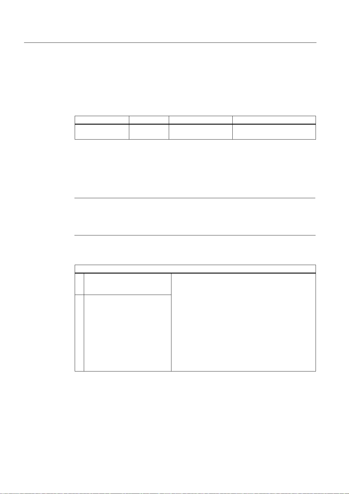
Maintenance and service
11.1 Removing and installing hardware components
11.1.2 Preventive maintenance
To maintain high system availability, we recommend the preventative exchange of those PC
components that are subject to wear. The table below indicates the intervals for this
exchange.
HDD Fan CMOS backup battery Air filter mat
3 years 3 years 5 years Depending on the degree of
soiling
11.1.3 Replacing filters
Preparing for filter replacement
Replacing filters
Note
You may only use filters of the same type. Information about original spare parts for
SIMATIC PCs is available on the Internet at http://www.siemens.com/asis
Filter meshes are available under the following order number: A5E01064980.
How to replace the filter
1. Open the front panel door by
approximately 45° to remove the
front panel surround
2. Remove the front cover to replace
the filter
SIMATIC Rack PC 847B
76 Operating Instructions, 06/2008, A5E02203168-01
Page 77
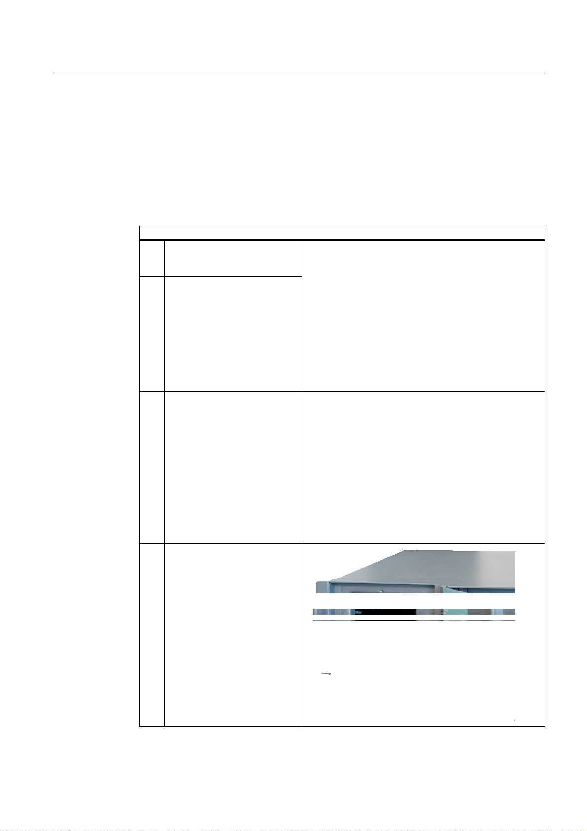
Maintenance and service
11.1 Removing and installing hardware components
11.1.4 Removing the device / drive cooling fan
Preparing for removal of the device fan
Unplug the device from mains.
Removing the fan
How to remove the device fan
1. Open the front panel door by
approximately 45° to remove the
front panel surround
2. Remove the front cover and
replace the filter if necessary
(you may only use filters of the
same type)
3. Loosen the knurled screw of the
fan bracket
4. Take the fan bracket out of the
enclosure
SIMATIC Rack PC 847B
Operating Instructions, 06/2008, A5E02203168-01
77
Page 78
Maintenance and service
11.1 Removing and installing hardware components
How to remove the device fan
5. Disconnect the fan connector
6. Loosen all body-bound rivets
and remove the fan from the
bracket
SIMATIC Rack PC 847B
78 Operating Instructions, 06/2008, A5E02203168-01
Page 79

Maintenance and service
11.1 Removing and installing hardware components
Installing the fan
NOTICE
Always install a fan of the same type!
CAUTION
Ensure that the arrow on the fan points away from the fan bracket. The fan blows cooling
air into the enclosure.
Fan mounting position
The picture shows the proper fan
mounting position. Observe the
direction of the arrow on the fan!
SIMATIC Rack PC 847B
Operating Instructions, 06/2008, A5E02203168-01
79
Page 80
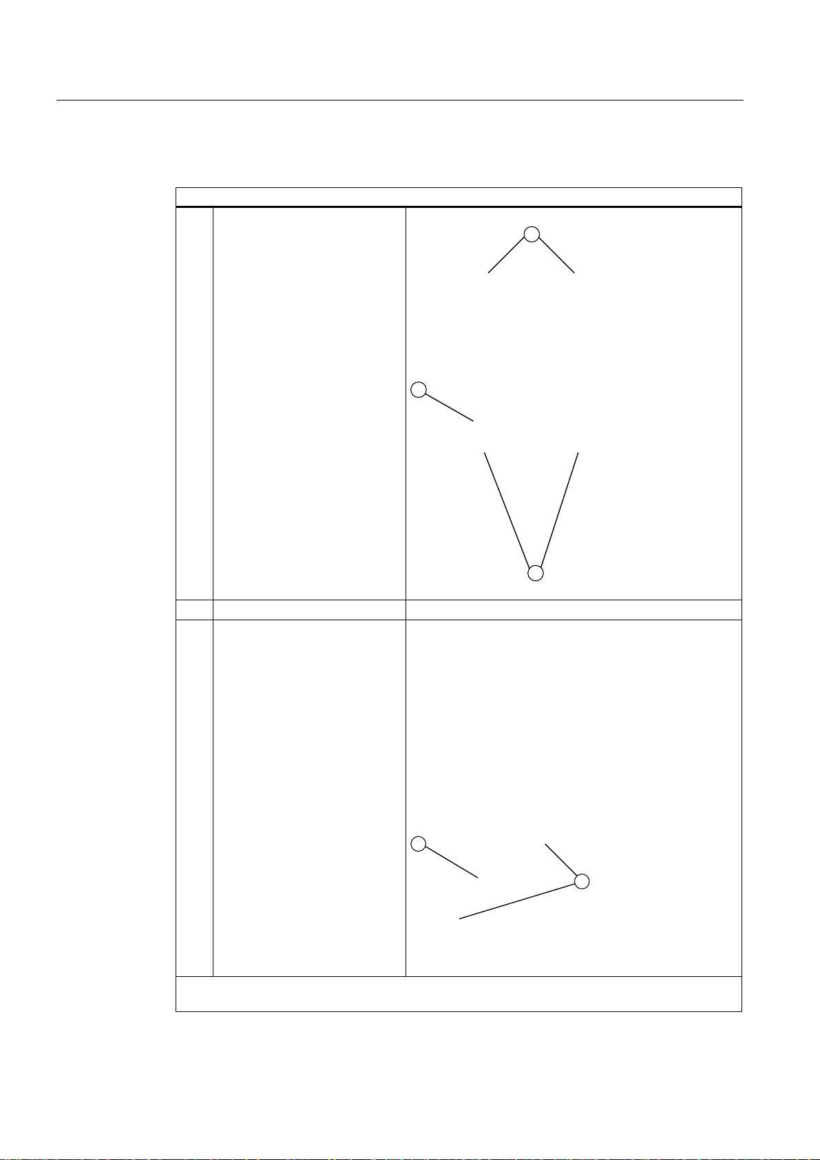
Maintenance and service
11.1 Removing and installing hardware components
Replacing drive fans
How to remove the drive fan
1. Remove the four screws (1) and
swivel the fan rack (2) out of the
enclosure
2. Disconnect the fan cable
3. Remove the two screws (1) of
the fan (2)
Install the fan in reverse order. Observe the direction of the arrow on the fan; the arrow points
towards the fan rack. The drive fan extracts hot air from the enclosure.
SIMATIC Rack PC 847B
80 Operating Instructions, 06/2008, A5E02203168-01
Page 81

Maintenance and service
11.1 Removing and installing hardware components
11.1.5 Replacing the backup battery
Items to observe for replacement
Disposal
Preparation
Note
Batteries are wearing parts. Backup batteries should be replaced at intervals of 5 years in
order to maintain PC functionality.
CAUTION
Risk of damage!
The lithium battery may only be replaced with an identical battery or with a type
recommended by the manufacturer (Order No.: A5E00047601). Information about original
spare parts for SIMATIC PCs is available on the Internet at http://www.siemens.com/asis
CAUTION
Used batteries must be disposed of in accordance with local regulations.
Note
The configuration data of the device may be deleted when you replace the backup battery,
depending on BIOS settings.
The configuration data are retained in the BIOS "Profile: User" setting; only the date and time
must be set again.
A table in which you can log your settings is available in the BIOS Setup section.
1. Isolate the device from mains and disconnect all connecting cables.
SIMATIC Rack PC 847B
Operating Instructions, 06/2008, A5E02203168-01
81
Page 82

Maintenance and service
11.1 Removing and installing hardware components
Replacing the battery
Procedure:
How to replace the battery
1. Open the device
2. Pull the battery out of the socket
3. Push the new battery into the socket
under slight pressure
4. Close the device
New BIOS Setup
Device configuration data may be deleted when you replace the backup battery, depending
on the settings in BIOS Setup, and must be configured again in BIOS Setup.
SIMATIC Rack PC 847B
82 Operating Instructions, 06/2008, A5E02203168-01
Page 83
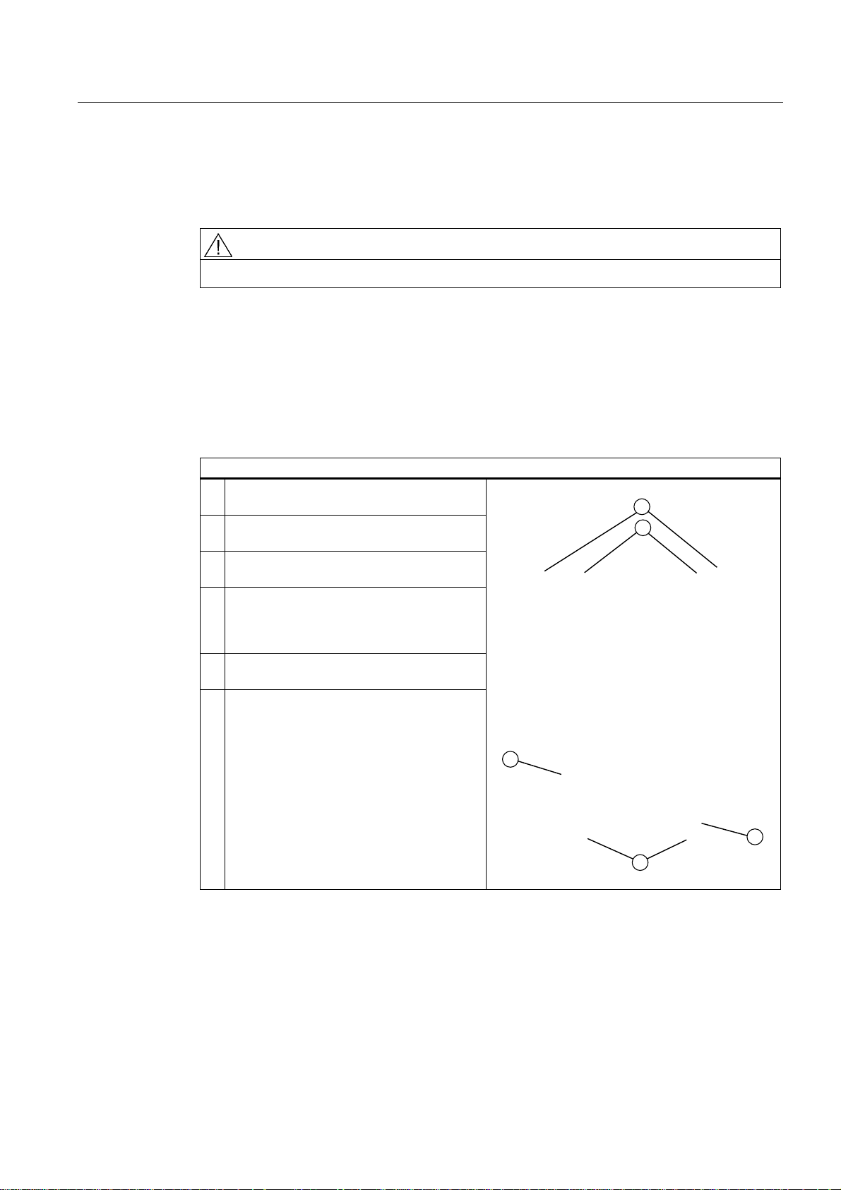
Maintenance and service
11.1 Removing and installing hardware components
11.1.6 Removing the power supply module
WARNING
Only qualified personnel are allowed to replace the power supply unit.
Preparations
1. Isolate the device from mains and disconnect all connecting cables.
2. Open the device.
Removing the power supply unit
How to remove the power supply unit
1. Disconnect the power cables from the disk
drives and motherboard.
2. Remove the tie-wraps holding the power
cables in the housing.
3. Remove the mounting screws (TORX T10)
(2) of the retainer panel.
4. Lift the power supply unit out of the
enclosure until you can access the power
cable of the floppy disk drive and of the bus
board.
5. Disconnect the power cables from the floppy
drive and from the bus board.
6. Remove the mounting screws (1) of the
power supply unit from the retainer panel.
SIMATIC Rack PC 847B
Operating Instructions, 06/2008, A5E02203168-01
83
Page 84
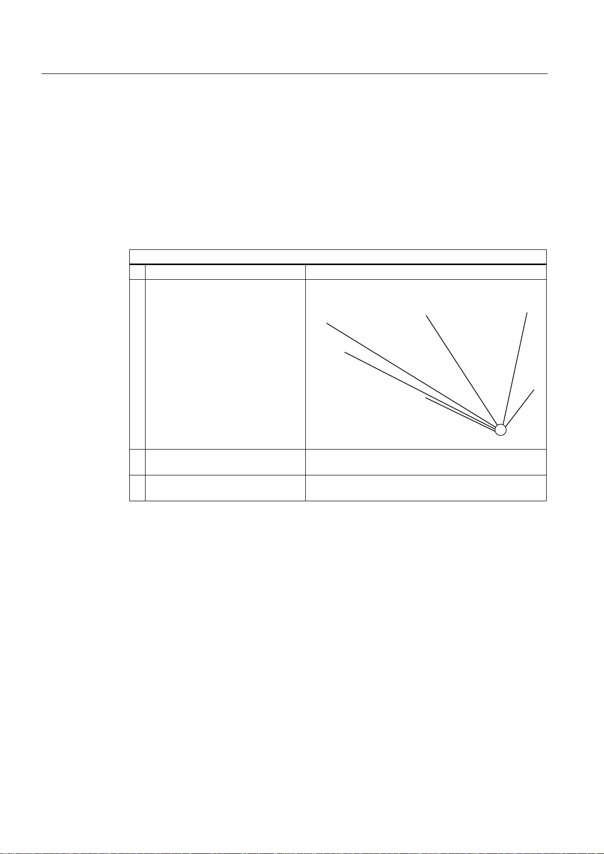
Maintenance and service
11.1 Removing and installing hardware components
11.1.7 Removing the bus board
Preparation
1. Isolate the device from mains and disconnect all connecting cables.
2. Open the device.
Removing the bus board
How to remove the bus board
1. Remove all modules from their slots
2. Remove the six screws (1) from the
bus board
3. Disconnect all connectors from the
bus board.
4. Remove the bus board from the
motherboard.
SIMATIC Rack PC 847B
84 Operating Instructions, 06/2008, A5E02203168-01
Page 85
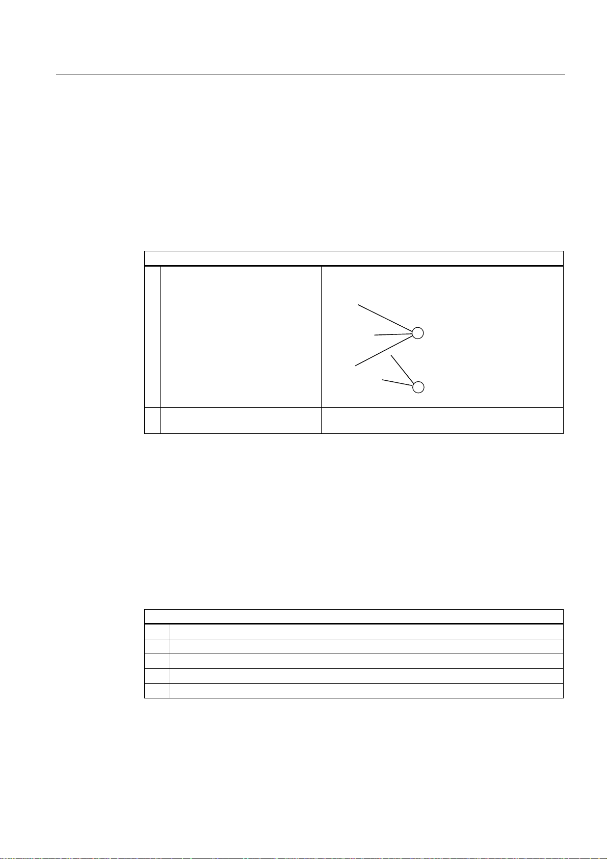
Maintenance and service
11.1 Removing and installing hardware components
11.1.8 Removing the Operator Panel
Preparation
1. Isolate the device from mains and disconnect all connecting cables.
2. Open the device.
Removing the operator panel
How to remove the operator panel
1. Loosen the mounting screws (1) on
the inside of the device front (3
x TORX)
2. Unplug the cable from the display
module
11.1.9 Removing the motherboard
Preparation
1. Isolate the device from mains and disconnect all connecting cables.
2. Open the device.
Removing the motherboard
How to remove the motherboard
1. Remove all modules from their slots.
2. Removing the bus board
3. Disconnect all cables from the motherboard, noting down their positions while doing so.
4. Remove the four screws of the CPU heatsink.
5. Remove the four screws and six hexagonal bolts from the motherboard.
SIMATIC Rack PC 847B
Operating Instructions, 06/2008, A5E02203168-01
85
Page 86
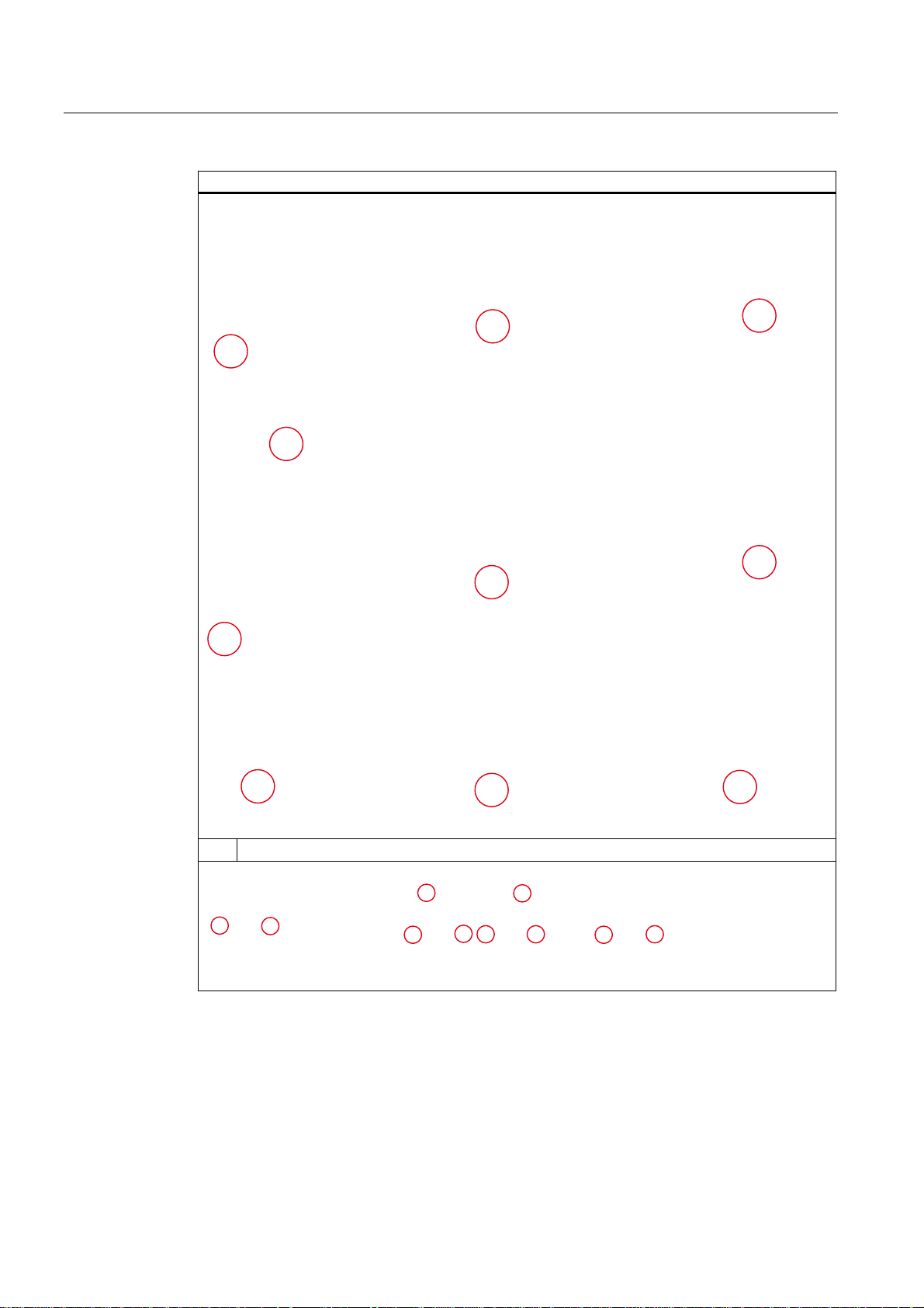
Maintenance and service
11.1 Removing and installing hardware components
How to remove the motherboard
6. Remove the hexagonal bolts at the interfaces.
The motherboard is supplied as spare part without processor, memory modules and bus
board.
SIMATIC Rack PC 847B
86 Operating Instructions, 06/2008, A5E02203168-01
Page 87

Maintenance and service
11.1 Removing and installing hardware components
11.1.10 Processor replacement
CAUTION
The processor may only be replaced by authorized technical personnel.
Preparation
1. Unplug the device from mains.
2. Open the device.
Removing the processor
How to remove the processor
1. Remove the four screws of the
processor heatsink and remove it
2. Open the processor retainer
SIMATIC Rack PC 847B
Operating Instructions, 06/2008, A5E02203168-01
87
Page 88
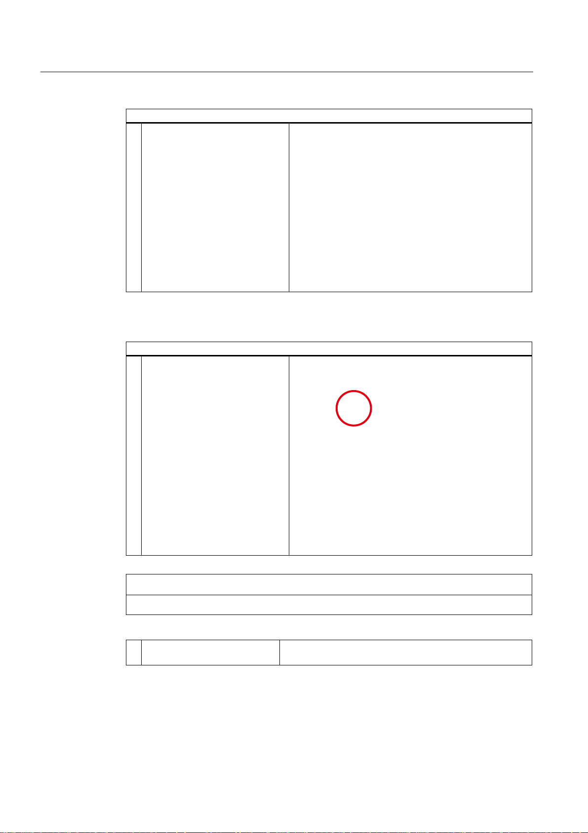
Maintenance and service
11.1 Removing and installing hardware components
How to remove the processor
3. Removing the processor
Installing the processor
How to install the processor
1. Inserting the processor
NOTICE
Make sure that the processor and socket coding match when inserting the processor.
2. Apply some heat-conductive
paste to the processor
SIMATIC Rack PC 847B
88 Operating Instructions, 06/2008, A5E02203168-01
Page 89

Maintenance and service
11.1 Removing and installing hardware components
CAUTION
The processor may overheat when the system is in operation!
Apply an even, thin film of the heat-conductive paste!
3. Insert the heatsink
4. Secure the heatsink using the
four screws: Insert the screws
diagonally and tighten them
evenly in order to avoid tilting.
SIMATIC Rack PC 847B
Operating Instructions, 06/2008, A5E02203168-01
89
Page 90

Maintenance and service
11.2 Reinstalling the software
11.2 Reinstalling the software
11.2.1 General installation procedure
If your software is corrupt, you can reinstall it using the recovery CD or DVD, the
Documentation and Drivers CD and the Restore DVD.
Recovery CD or DVD:
The recovery CD/DVD contains the Windows user interface with tools for configuring the
hard drives, and for installation of the operating system and the languages supported by the
operating system (MUI).
The basic language of the operating system to be installed is English. If you want to integrate
additional languages, you will need to subsequently install them from Recovery CD2 or DVD.
Documentation and Drivers CD:
Contains the documentation and the hardware drivers.
Restore DVD:
Contains a hard disk image file with the original factory software (operating system with
installed hardware drivers and monitoring software, such as SOM).
SIMATIC Rack PC 847B
90 Operating Instructions, 06/2008, A5E02203168-01
Page 91

Maintenance and service
11.2 Reinstalling the software
11.2.2 Restoring the Factory State of the Software Using the Restore DVD
You can restore the software to the original factory state using the Restore CD (not included
in all package variants). The DVD contains the necessary images and tools for transferring
the factory software to the hard disk of your PC. You can restore the entire hard disk with
drive C: (system) and drive D: or only drive C:. This allows you to retain any user data on
drive D:.
Retrieving authorizations or license keys from the hard disk
● Check whether you can retrieve your authorization or license key from the hard disk and
perform this procedure as described below if possible.
● If backup is not possible, please contact Customer Support. There you can obtain
information necessary for software authorization.
CAUTION
If "Restore system partition only" is set all data on drive C: (system partition) will be
deleted. All data, user settings and all authorizations or license keys on drive C: are lost!
All data on drive C: of the hard disk will be deleted. Setup formats the hard disk and
installs the original factory software.
If "Restore entire hard disk" is set ALL data, user settings, authorizations or license keys
will be lost on the hard disk.
Restoring factory state
To restore the delivery state:
● Place the Restore DVD into the drive and restart the device using the on/off switch.
● When BIOS outputs the message
Press <F2> to enter Setup or <ESC> to show Boot menu
the ESC key. The "Boot Menu" is displayed when initialization is completed.
● Select the optical drive using the cursor keys.
● Follow the on-screen instructions.
CAUTION
All existing data, programs, user settings and authorizations or license keys will be
deleted from the hard disk and are therefore lost.
For information on the functions, refer to the README.TXT file on the Restore DVD.
SIMATIC Rack PC 847B
Operating Instructions, 06/2008, A5E02203168-01
91
Page 92

Maintenance and service
11.2 Reinstalling the software
11.2.3 Installing Windows
Use the Recovery CD/DVD to install Windows to suit your particular requirements. You also
need the "Documentation and Drivers" CD supplied. Additional controllers unknown to the
operating system must be made known to the recovery system and to the Windows
operating system.
1. Press the F6 or the "Load Driver" icon key while booting and follow the on-screen
instructions. During the rest of the installation, you will be asked several times for the
missing driver of the controller.
Booting from recovery CD or DVD
1. Press <ESC> when BIOS outputs the message
Press <F2> to enter Setup or <ESC> to show the Boot menu
to boot from the Recovery CD or DVD. The boot menu displayed after initialization
indicates all boot devices.
2. Select the CD/DVD drive.
Follow the instructions on the screen until the "Siemens SIMATIC Recovery" window is
displayed.
When using the recovery function with Windows Vista, confirm that you want to boot from
CD or DVD as soon as you restart. Otherwise the system boots from hard disk if you
have a bootable hard disk installed.
The following sections describe older Windows operating systems. Recovery for Vista is
described as of section 11.2.6.
SIMATIC Rack PC 847B
92 Operating Instructions, 06/2008, A5E02203168-01
Page 93
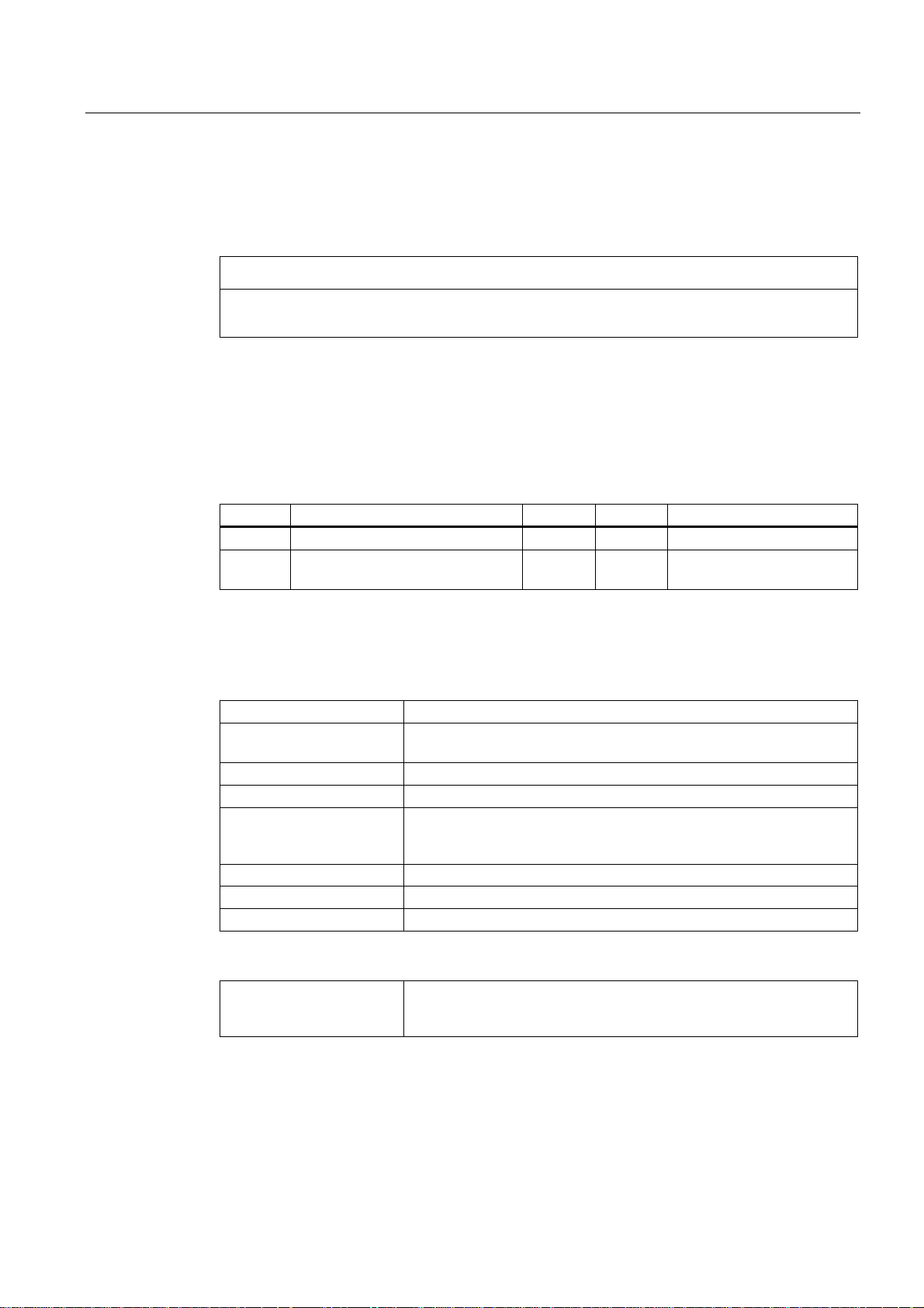
Maintenance and service
11.2 Reinstalling the software
11.2.3.1 Setting up partitions for Windows 2000, XP, Server 2003 operating systems
The hard disk needs to be partitioned after installation of a new hard disk, if partitions are
faulty, of if the user wants to change the partition sizes.
CAUTION
All data on the hard disk are lost if you delete / setup partitions or logical DOS volumes. All
partitions on the hard disk are deleted.
Microsoft recommends setup of the NTFS file system on hard disk partitions in Windows
operating systems. Procedure:
Setting up partitions
When shipped, the partitions are set up as follows:
Partition Operating system Name Size File system
First Windows 2000, XP, Server 2003 SYSTEM 20 GB NTFS not compressed
Second Windows 2000, XP, Server 2003 DATA Remaind
1. Boot from the Recovery CD and then follow the on-screen instructions until the Recovery
2. Start the DiskPart tool in the "Siemens SIMATIC Recovery“ window. Enter the following
list disk Displays all available hard disks.
select disk 0 For selecting the disk to be reconfigured. 0 selects the first hard disk
list partition Displays all partitions on the selected hard disk.
clean Deletes the entire selected hard disk. All information stored is lost.
create partition primary
size=n
select partition 1 Select the primary partition
active Activates the selected partition
exit Closes the DiskPart tool.
NTFS not compressed
er
functions window is displayed.
commands in the displayed command interface:
drive.
Creates a primary partition with a size of n MB on the selected HDD.
Default values:
n = 20000 for Windows 2000, XP, Windows Server 2003
Additional DiskPart functions:
Help Shows all DiskPart commands. Additional command parameters
SIMATIC Rack PC 847B
Operating Instructions, 06/2008, A5E02203168-01
entered are described in the help extension.
Example: create partition help
93
Page 94

Maintenance and service
11.2 Reinstalling the software
Note
After having modified the HDD configuration using DiskPart, restart the PC for the changes
to go into effect.
Boot once again from the Recovery CD to format the partitions.
Formatting the primary partition
1. Boot from the Recovery CD to format the partitions. Follow the on-screen instructions
until the Recovery functions window is displayed.
2. Select "Start command prompt" in the Recovery functions window. Enter the following
command in the command interface:
format DL:/FS:File System
DL = drive letter of the partition to be formatted. Valid values: C, D, E, F etc.
File system = specifies the type of file system. Valid values: FAT, FAT32, NTFS.
NTFS is the factory setting for all Windows operating systems.
Example of a master IDE HDD
format C:/FS:NTFS
format /? Shows all command parameters.
SIMATIC Rack PC 847B
94 Operating Instructions, 06/2008, A5E02203168-01
Page 95

Maintenance and service
11.2 Reinstalling the software
11.2.3.2 Installing Microsoft Windows operating systems
This CD contains encrypted data that can only be transferred to this system.
1. Boot from the Recovery CD and then follow the on-screen instructions until the Recovery
functions window is displayed.
2. Select "Recovery Windows ..." in the "Siemens SIMATIC Recovery" window.
3. Follow the on-screen instructions.
Note
Make sure that sufficient free space is left on the drive after the transfer of selected
recovery data:
500 MB for Windows 2000
1500 MB for Windows XP
1500 MB for Windows Server 2003
4. Select "Start command prompt" in the Recovery functions window.
5. Enter the following commands in the command interface:
DL:
cd \I386
Winnt32.bat
DL: Drive letter of the folder which contains the I386 directory.
6. The preparation of the Windows installation is displayed.
7. When this operation completed, close the command prompt by entering the exit
command.
8. Close the Siemens SIMATIC Recovery window by clicking the "Finish" button.
9. Setup automatically restarts the system and completes the installation of Windows.
10. Follow the on-screen instructions.
Note
References required by professional users of Microsoft Windows (not included in the
scope of delivery):
Microsoft Windows 2000 Professional Resource Kit (MSPress No 274) or
Microsoft Windows XP Professional, Technical Reference (MSPress No 934)
Microsoft Windows Server 2003, Planning Server Deployment for Windows Server 2003,
Technical Reference (MSPress No. 420)
These manuals contain specific information for administrators who install, manage and
integrate Windows in networks or multi-user environments.
SIMATIC Rack PC 847B
Operating Instructions, 06/2008, A5E02203168-01
95
Page 96

Maintenance and service
11.2 Reinstalling the software
Information for systems with RAID controllers (optional)
Unknown additional controllers must be made known to the Windows operating system.
1. Press F6 key within the startup sequence and follow the on-screen instructions. In the
next installation phases you are prompted several times to insert a floppy disk which
contains the missing RAID driver. The driver is available on the included "Documentation
and Drivers" CD in the Drivers\RAID\Intel directory.
2. Copy the corresponding driver to a blank, formatted floppy disk.
3. After the message to press the F6 key, select the driver "Intel(R) 82801GR/GH SATA
RAID" on the screen in a selection window. To display the proposed list completely, you
may need to scroll down with the arrow keys.
SIMATIC Rack PC 847B
96 Operating Instructions, 06/2008, A5E02203168-01
Page 97

Maintenance and service
11.2 Reinstalling the software
11.2.4 Setting up the language selection by means of the Multilanguage User Interface
(MUI)
Preinstalled languages such as German, French, Spanish or Italian can be set up directly.
Run MUISETUP.EXE from Recovery CD 2 to install additional languages. The program
displays all available languages.
Setting up the language selection for Windows 2000 MUI
The Multilanguage User Interface (MUI) of Windows 2000 allows you to change the menu
and dialog language.
The dialog language for Windows 2000 menus and for the keyboard layout are set in the
corresponding Control Panel dialog by selecting:
Start > Settings > Control Panel > Regional Options > General tab, Setting for the current user field
and Language settings for the system field and the Keyboard layout field in the Input Locales tab.
In addition to the menu and dialog language settings, also set the default language by
selecting Set Default... in the Regional Options dialog box.
The default language setting of your Windows 2000 installation is English with US keyboard
layout. To change to another language and keyboard layout, open the Control Panel and
select:
Start > Settings > Control Panel > Regional Options>General tab,Menus and dialogs field and
Language settings for the system field and the Input language field in the Input Locales tab.
Language selection in Windows XP Professional and Windows Server 2003
The Multilanguage User Interface (MUI) in Windows XP allows you to change the menu and
dialog language.
The default language setting of your Windows installation is English with US keyboard
layout. You can change the language in the Control Panel. Select:
Start > Control Panel > Regional and Language, Languages tab Language used in menus and
dialogs field.
For the Date, Time, Language, and Regional Options, set the default as non-Unicode programs
under Advanced in addition to the language for menus and dialogs.
SIMATIC Rack PC 847B
Operating Instructions, 06/2008, A5E02203168-01
97
Page 98

Maintenance and service
11.2 Reinstalling the software
11.2.5 Recovery of Windows Vista
To recover Windows Vista, there is a full graphical user interface available. It may take
several minutes before the first input window appears. In this window, you can set the time
and currency formats and select the keyboard language.
English is the basic language and other languages can be installed later with the MUI. The
MUI is on the recovery DVD.
Now follow the on-screen instructions. It may take several minutes before the next prompt for
the product key is displayed.
Note
Due to the previous activation, you do not need to enter the product key (COA number). This
is entered automatically during the installation.
Setting up and formatting partitions
After you have installed a new hard disk, or if partitions are faulty, or when you wish to
change the partitioning on your hard disk, you need to create or reconfigure partitions on the
hard disk.
In the next dialog box, you can set up the hard disk according to your requirements and add
controllers that are not yet known to the system.
SIMATIC Rack PC 847B
98 Operating Instructions, 06/2008, A5E02203168-01
Page 99
Maintenance and service
11.2 Reinstalling the software
Options Meaning
Drive options (advanced) Further functions are displayed with which you can set up the hard
disk.
Load Driver To add new drivers, for example the driver for RAID.
Options Meaning
Refresh Updating
Delete Deleting a partition
Format Formatting a partition
New Creating new partitions
Load Driver To add new drivers, for example the driver for RAID
Extend Changing the partition size
The first partition should be at least 25 GB. The operating system must be installed on this
partition. You can use the rest of the hard disk as a data partition. Both partitions must be
installed as the NTFS file system.
SIMATIC Rack PC 847B
Operating Instructions, 06/2008, A5E02203168-01
Any error messages that occur are displayed behind this icon, for
example if the hard disk was not formatted in the required "NTFS"
format.
99
Page 100

Maintenance and service
11.2 Reinstalling the software
When shipped, the partitions are set up as follows:
Partition Operating system Name Size File system
First Windows Vista SYSTEM 25 GB NTFS not compressed
Second Windows Vista DATA Remainder NTFS not compressed
Following a reboot, Windows Vista is installed on the hard disk. This process takes at least
20 minutes.
Note
If you want to reinstall drivers from the integrated floppy disk drive, select Floppy Drive (A:) .
If you want to reinstall drivers from a USB floppy disk drive, select Floppy Drive (B:) .
Now follow the instructions on the screen.
Note
If you want to use Microsoft Windows as a professional user, you will need the following
manual (not supplied):
Windows Vista Inside Out
This manual contains information specifically for administrators involved in installing,
managing and integrating Windows in networks or multi-user environments.
Setting up language options in Windows Vista
With the Multilanguage User Interface (MUI), you can set up the Windows menus and
dialogs for additional languages. When shipped, Windows Vista is installed with English
menus and dialogs. You can change this in the Control Panel with the "Regional and
Language options" or "Time and Date" dialogs.
Here, you can change all system formats:
Start > Control Panel > Clock, Language, and Region > Change display language >
Regional and Language options
Here, you can only change the date and time formats:
Start > Control Panel > Clock, Language, and Region > Change display language > Time
and Date
If you want to install additional languages, you can install these later in the Control Panel, as
follows. You will find the necessary files on the recovery DVD in the "Language packs"
folder.
Start > Control Panel > Clock, Language, and Region > Change display language >
Regional and Language options > Keyboards and Languages
Additional languages can be integrated via Windows Update.
SIMATIC Rack PC 847B
100 Operating Instructions, 06/2008, A5E02203168-01
 Loading...