

Page 1

SCALANCE WLC711
___________________
___________________
___________________
___________________
___________________
___________________
___________________
___________________
SIMATIC NET
Industrial Wireless LAN
SCALANCE WLC711
Getting Started
04/2016
C7900
Preface
Security recommendations
1
Description
2
Getting started
3
Basic configuration with the
wizard
4
Managing access points
5
Configuring specific use
cases with the wizard
6
Optional configuration
7
0-G8976-C269-07
Page 2

Siemens AG
Division Process Industries and Drives
Postfach 48 48
90026 NÜRNBERG
GERMANY
Document order number: C79000-G8976-C269-06
Ⓟ
Copyright © Siemens AG 2011 - 2016.
All rights reserved
Legal information
Warning notice system
DANGER
indicates that death or severe personal injury will result if proper precautions are not taken.
WARNING
indicates that death or severe personal injury may result if proper precautions are not taken.
CAUTION
indicates that minor personal injury can result if proper precautions are not taken.
NOTICE
indicates that property damage can result if proper precautions are not taken.
Qualified Personnel
personnel qualified
Proper use of Siemens products
WARNING
Siemens products may only be used for the applications described in the catalog and in the relevant technical
maintenance are required to ensure that the products operate safely and without any problems. The permissible
ambient conditions must be complied with. The information in the relevant documentation must be observed.
Trademarks
Disclaimer of Liability
This manual contains notices you have to observe in order to ensure your personal safety, as well as to prevent
damage to property. The notices referring to your personal safety are highlighted in the manual by a safety alert
symbol, notices referring only to property damage have no safety alert symbol. These notices shown below are
graded according to the degree of danger.
If more than one degree of danger is present, the warning notice representing the highest degree of danger will
be used. A notice warning of injury to persons with a safety alert symbol may also include a warning relating to
property damage.
The product/system described in this documentation may be operated only by
task in accordance with the relevant documentation, in particular its warning notices and safety instructions.
Qualified personnel are those who, based on their training and experience, are capable of identifying risks and
avoiding potential hazards when working with these products/systems.
Note the following:
documentation. If products and components from other manufacturers are used, these must be recommended
or approved by Siemens. Proper transport, storage, installation, assembly, commissioning, operation and
All names identified by ® are registered trademarks of Siemens AG. The remaining trademarks in this publication
may be trademarks whose use by third parties for their own purposes could violate the rights of the owner.
We have reviewed the contents of this publication to ensure consistency with the hardware and software
described. Since variance cannot be precluded entirely, we cannot guarantee full consistency. However, the
information in this publication is reviewed regularly and any necessary corrections are included in subsequent
editions.
for the specific
11/2016 Subject to change
Page 3

Preface
Introduction
Who is this document intended for?
Purpose of this document
Validity of this document
By using the Industrial Wireless LAN controller SCALANCE WLC711 along with controllerbased access points, it is possible to set up a single wireless infrastructure for the entire
company. This achieves a high degree of flexibility since mobile subscribers (for example a
laptop) move both in the office and in the automation network and can change over
seamlessly between these networks (roaming). This means that data can be accessed from
anywhere in the company over wireless.
Thanks to the use of a centralized security mechanism for each user group, data is protected
from unauthorized access and manipulation.
The controller-based access points SCALANCE W78xC support the WLAN standards IEEE
802.11a/b/g ad 802.11n and are connected to the IWLAN controller SCALANCE WLC via
gigabit Ethernet. The same applies to the access points SCALANCE W786C, with which a
connection via fiber-optic is possible depending on the version. The controller-based access
points SCALANCE W786-2HPW support the WLAN standards IEEE 802.11a/b/g and are
connected to the IWLAN controller SCALANCE WLC via fast Ethernet or fiber-optic cable.
One requirement for operation is always the use of the IWLAN controller SCALANCE WLC
which makes the group configuration of access points possible. This allows a widespread
IWLAN infrastructure to be represented clearly. The central management with the IWLAN
controller also allows the recording of disruptions, monitoring and documentation of
statistics.
The Getting Started is intended for system administrators who want to configure the wireless
LAN controller SCALANCE Industrial Wireless LAN controller WLC711 and the access
points with the Web Based Management (WBM) of the SCALANCE Industrial Wireless LAN
controller and access points.
This document provides you with a general overview of the functions of the WBM
SCALANCE Industrial Wireless LAN controller and access points. The Getting Started will
quickly help you to learn about configuring the devices.
We recommend that you read the Getting Started not selectively but rather from front to
back. You will get to know the important components that can help you during configuration.
SCALANCE WLC711
Getting Started, 04/2016, C79000-G8976-C269-07
This document is valid for the SCALANCE IWLAN controller WLC711 and the controllerbased SCALANCE W78xC access points as of firmware version V 9.21.
3
Page 4

Preface
SIMATIC NET glossary
Security messages
Note
Siemens offers IT security mechanisms for its automation and drive product portfolio in order
to support the safe operation of the plant/machine. Our products are also continuously
developed further with regard to IT security. We therefore recommend that
check for updates of our products and that you only use the latest versions. You will find
information in:
Here, you can register for a product
For the safe operation of a plant/machine, however, it is also necessary to integrate the
automation components into an overall IT security concept for the entire plant/machine,
whic
Products from
Explanations of many of the specialist terms used in this documentation can be found in the
SIMATIC NET glossary.
You will find the SIMATIC NET glossary here:
● SIMATIC NET Manual Collection or product DVD
The DVD ships with certain SIMATIC NET products.
● On the Internet under the following address:
50305045 (https://support.industry.siemens.com/cs/ww/en/view/50305045)
you regularly
http://www.siemens.com/industrialsecurity. (http://www.siemens.com/industrialsecurity.)
-specific newsletter.
h corresponds to the state-of-the-art IT technology. You will find information on this in:
https://support.industry.siemens.com (https://support.industry.siemens.com/cs/de/en/)
other manufacturers that are being used must also be taken into account.
SCALANCE WLC711
4 Getting Started, 04/2016, C79000-G8976-C269-07
Page 5

Table of contents
Preface ................................................................................................................................................... 3
1 Security recommendations ...................................................................................................................... 7
2 Description ............................................................................................................................................ 13
3 Getting started ...................................................................................................................................... 17
4 Basic configuration with the wizard ........................................................................................................ 23
5 Managing access points ........................................................................................................................ 35
6 Configuring specific use cases with the wizard ...................................................................................... 61
7 Optional configuration ........................................................................................................................... 79
1.1 General information .................................................................................................................. 7
1.2 Security recommendations ....................................................................................................... 8
2.1 General ................................................................................................................................... 13
2.2 Requirement for configuration ................................................................................................ 15
2.3 LED display ............................................................................................................................. 16
3.1 Sequence ................................................................................................................................ 17
3.2 Logon ...................................................................................................................................... 19
3.3 Shutting down and turning off ................................................................................................. 21
4.1 Procedure - "Basic Installation Wizard" page ......................................................................... 25
4.2 Procedure - "Management" page ........................................................................................... 28
5.1 Commissioning access points ................................................................................................ 35
5.2 Registering access points ....................................................................................................... 39
5.3 Configuring access points ....................................................................................................... 45
5.3.1 Single configuration ................................................................................................................ 45
5.3.2 Multiple configuration .............................................................................................................. 58
6.1 Use case: Bridged at WLC ..................................................................................................... 61
6.2 Use case: Bridged at AP ......................................................................................................... 70
7.1 Expanding the number of manageable access points ............................................................ 79
7.2 Access using the Command Line Interface (CLI) ................................................................... 82
7.3 Data backup ............................................................................................................................ 84
7.4 Using reports ........................................................................................................................... 87
7.5 Using policies .......................................................................................................................... 89
7.6 Authentication via RADIUS server .......................................................................................... 91
7.7 User configuration ................................................................................................................... 94
SCALANCE WLC711
Getting Started, 04/2016, C79000-G8976-C269-07
5
Page 6

Table of contents
Index .................................................................................................................................................... 97
SCALANCE WLC711
6 Getting Started, 04/2016, C79000-G8976-C269-07
Page 7

1
1.1
General information
Note
Note the information in the SCALANCE WLC711 user guide and the compact operating
instructions SCALANCE WLC711.
Notes on secure network design
Use WPA2/ WPA2-PSK with AES
Protect your network against man-in-the-middle attacks
Use SNMPv3
To protect your network from attacks, note the following points:
●
To prevent misuse of a password, use only WPA2/AES. WPA2/ WPA2-PSK with AES
provides the highest security.
●
To protect your network from man-in-the-middle attacks, a network topology is
recommended, that makes it more difficult for an attacker to tap into the communications
path between two end devices.
– You can, for example, protect WLAN devices by arranging so that the management
port is accessible only via a separate management VLAN.
– You can also install a separate HTTPS certificate on a WLAN client / access point.
The HTTPS certificate checks the identity of the device and controls the encrypted
data exchange. You can install the HTTPS certificate via HTTP.
●
SNMPv3 provides you with highest possible security when accessing the WLAN devices
via SNMP.
SCALANCE WLC711
Getting Started, 04/2016, C79000-G8976-C269-07
7
Page 8

Security recommendations
1.2
Security recommendations
General
Physical access
Software (security functions)
1.2 Security recommendations
To prevent unauthorized access, note the following security recommendations.
● You should make regular checks to make sure that the device meets these
recommendations and/or other security guidelines.
● Evaluate your plant as a whole in terms of security. Use a cell protection concept with
suitable products.
● When confidential zones are used, the internal and external network are disconnected, an
attacker cannot access the data from the outside.
● Operate the device only within a protected network area.
● Use additional devices with VPN functionality (e.g. SCALANCE S) to encrypt and
authenticate communication from and to the devices.
● For data transfer via a non-secure network, use an encrypted VPN tunnel (IPsec) by
using additional devices with VPN functionality (e.g. SCALANCE S).
● For operation of the device in a non-secure infrastructure no product liability will be
accepted.
● Separate connections correctly (WBM. Telnet, SSH etc.).
● Restrict physical access to the device to qualified personnel.
● Lock unused physical ports on the device. Unused ports can be used to gain forbidden
access to the plant.
● Keep the software up to date. Check regularly for security updates of the product.
You will find information on this on the Internet pages "Industrial Security
(http://www.siemens.com/industrialsecurity".
● Inform yourself regularly about security advisories and bulletins published by Siemens
ProductCERT (http://www.siemens.com/cert/en/cert-security-advisories.htm).
● Only activate protocols that you really require to use the device.
● Use the security functions such as address translation with NAT (Network Address
Translation) or NAPT (Network Address Port Translation) to protect receiving ports from
access by third parties.
● Restrict access to the device with a firewall or rules in an access control list (ACL -
Access Control List).
● If RADIUS authentication is via remote access, make sure that the communication is
within the secured network area or is via a secure channel.
● The option of VLAN structuring provides good protection against DoS attacks and
unauthorized access. Check whether this is practical or useful in your environment.
SCALANCE WLC711
8 Getting Started, 04/2016, C79000-G8976-C269-07
Page 9

Security recommendations
Passwords
Keys and certificates
1.2 Security recommendations
● Enable logging functions. Use the central logging function to log changes and access
attempts centrally. Check the logging information regularly.
● Configure a Syslog server to forward all logs to a central location.
● Use WPA2/ WPA2-PSK with AES to protect the WLAN.
● Define rules for the use of devices and assignment of passwords.
● Regularly update passwords and keys to increase security.
● Change all default passwords for users before you operate the device.
● Only use passwords with a high password strength. Avoid weak passwords for example
password1, 123456789, abcdefgh.
● Make sure that all passwords are protected and inaccessible to unauthorized personnel.
● Do not use the same password for different users and systems or after it has expired.
This section deals with the security keys and certificates you require to set up HTTPS (
HyperText Transfer Protocol Secured Socket Layer).
● We strongly recommend that you create your own HTTPS certificates and make them
● Handle user-defined private keys with great caution if you use user-defined SSH or SSL
● Use the certification authority including key revocation and management to sign the
● Verify certificates and fingerprints on the server and client to avoid "man in the middle"
● We recommend that you use certificates with a key length of 2048 bits.
● Change keys and certificates immediately, if there is a suspicion of compromise.
available.
There are preset certificates and keys on the device. The preset and automatically
created HTTPS certificates are self-signed.
We recommend that you use HTTPS certificates signed either by a reliable external or by
an internal certification authority. The HTTPS certificate checks the identity of the device
and controls the encrypted data exchange. You can install the HTTPS certificate via the
WBM (System > Load and Save).
keys.
certificates.
attacks.
SCALANCE WLC711
Getting Started, 04/2016, C79000-G8976-C269-07
9
Page 10

Security recommendations
Secure/non-secure protocols
1.2 Security recommendations
● Avoid and disable non-secure protocols, for example Telnet and TFTP. For historical
reasons, these protocols are still available, however not intended for secure applications.
Use non-secure protocols on the device with caution.
● The following protocols provide secure alternatives:
– SNMPv1/v2 → SNMPv3
Check whether use of SNMPv1 is necessary. SNMPv1 is classified as non-secure.
Use the option of preventing write access. The product provides you with suitable
setting options.
If SNMP is enabled, change the community names. If no unrestricted access is
necessary, restrict access with SNMP.
Use SNMPv3 in conjunction with passwords.
– HTTP → HTTPS
– SNTP → NTP
● Use secure protocols when access to the device is not prevented by physical protection
measures.
● To prevent unauthorized access to the device or network, take suitable protective
measures against non-secure protocols.
● If you require non-secure protocols and services, operate the device only within a
protected network area.
● Restrict the services and protocols available to the outside to a minimum.
SCALANCE WLC711
10 Getting Started, 04/2016, C79000-G8976-C269-07
Page 11

Security recommendations
Port list
Component
Protocol
Soruce
Port
Destination Port
Service
Remark
Require
Firewall
to open
Source
Destination
(TCP/UDP)
Ports for AP/Controller Communication
Management and Data Tunnel
Management and Data Tunnel
between AP and Controller
WASSP
AP and Controller
WASSP
AP and Controller
Access Point
Controller
UDP
Any
13907
WASSP
AP Registration to Controller
Yes
Server
for AP
Access Point
Controller
UDP
Any
427
SLP
AP Registration to Controller
Optional
Controller
Access Point
TCP/UDP
Any
69
TFTP
AP image transfer
Yes 1
Access Point
Controller
TCP/UDP
Any
69
TFTP
AP image transfer
Yes 1
Controller
Access Point
TCP/UDP
Any
22
SCP
AP traces
Yes
2003
Any
Access Point
TCP/UDP
Any
22
SSH
Remote AP login (if enabled)
Optional
Ports for Controller Management
Any
Controller
TCP/UDP
Any
5825
HTTPS
Controller GUI access
Yes
Any
Controller
TCP/UDP
Any
161
SNMP
Controller SNMP access
Yes
Trap
Ports for Inter Controller Mobility and Availability
nel
Controller
Controller
TCP
Any
427
SLP
SLP Directory
Yes
Controller
Controller
TCP
Any
20506
Langley
Remote Langley Secure
Yes
Controller
Controller
TCP
Any
60606
Mobility
VN MGR
Yes
Controller
Controller
TCP
Any
123
NTP
Availability time sync
Yes
DA
for SLP DA request
1.2 Security recommendations
The following table provides an overview of the ports through which the IWLAN
controller/access point communicate. Ports may need to be opened for correct working in the
network. Keep this in mind when configuring a firewall.
Controller Access Point UDP Any 13910 WASSP
between AP and Controller
Access Point Controller UDP Any 13910 WASSP
Controller Access Point UDP 4500 Any Secured
Access Point Controller UDP Any 4500 Secured
Access Point Controller UDP Any 67 DHCP
Any Access Point TCP Any 2002,
Any Controller TCP/UDP Any 22 SSH Controller CLI access Yes
RCAPD AP Real Capture (if enabled) Optional
Management Tunnel between
Management Tunnel between
If Controller is DHCP Server
Yes
Yes
Optional
Optional
Optional
Any Controller TCP/UDP Any 162 SNMP
Controller Controller UDP Any 13911 WASSP Mobility and Availability Tun-
Controller DHCP Server UDP Any 67 SLP Asking DHCP Server for SLP
DHCP Server Controller UDP Any 68 SLP Response from DHCP Server
SCALANCE WLC711
Getting Started, 04/2016, C79000-G8976-C269-07
Controller SNMP access Yes
Yes
Yes
Yes
11
Page 12

Security recommendations
Component
Protocol
Soruce
Port
Destination Port
Service
Remark
Require
Firewall
to open
Source
Destination
(TCP/UDP)
Core Back-End Communication
syslog server
zation
ing
(DAS)
(lbs)
point
er
1
control tunnel is enabled TFTP exchanges take place within the secure tunnel and port 69 is not used
1.2 Security recommendations
Controller DNServer UDP Any 53 DNS If using DNS Optional
Controller Syslog Server UDP Any 514 Syslog If Controller logs to external
Optional
Controller RADIUS
Server
UDP Any 1812 RADIUS
Authentication
and
Authori-
Controller RADIUS
Server
Dynamic Au-
Controller UDP Any 3799 Dynamic
thorization
Client (typically
NAC)
Controller AeroScout
Server
UDP Any 1813 RADIUS
Account-
Authorization
Server
UDP 1144 12092 Location-
Based
Service
Proxy
(lbs)
AeroScout
Server
Controller UDP 12092 1144 Location-
Based
Service
Proxy
Controller Check Point UDP Any 18187 Check-
If using RADIUS AAA Optional
If enabled RADIUS account-
Optional
ing
Request from Dynamic Au-
Optional
thorization Client to disconnect a specific client
AeroScout Location-Based
Optional
Service
AeroScout Location-Based
Optional
Service
Logging to Check Point Serv-
Optional
TFTP uses port 69 only when the secure control tunnel is NOT enabled between the AP and controller. If the secure
SCALANCE WLC711
12 Getting Started, 04/2016, C79000-G8976-C269-07
Page 13

2
2.1
General
Information
Siemens Customer Support
Related information can be found on the accompanying SIMATIC NET IWLAN CD:
Which access points can be used?
Note
Detection of W788C-2 M12 EEC devices
During detection of devices, the devices of the
W788C
How is data transferred?
If you have questions or problems, contact Siemens Customer Support at the following
address:
● https://support.industry.siemens.com
● BAK W78xC
● BAK W786-2HPW
● SCALANCE W-700 configuration manual
To achieve an optimum WLAN, the following SCALANCE wireless LAN access points are
ideal:
● SCALANCE wireless LAN W78xC access points
● SCALANCE Wireless LAN access points W788C-2 RJ-45
● SCALANCE Wireless LAN access points W788C-2 M12
● SCALANCE Wireless LAN access points W788C-2 M12 EEC
● SCALANCE Wireless LAN access points W786-2HPW
-2 M12
To transfer the data, the SCALANCE WLC711 has the following RJ-45 Ethernet connectors:
● Management port: "admin" interface. The configuration data is transferred at this port at
10/100/1000 Mbps.
● Data port: "esa0" interface. At this port, the data is transferred at 10/100/1000 Mbps.
You will find further information in the compact operating instructions SCALANCE WLC711.
SCALANCE WLC711
Getting Started, 04/2016, C79000-G8976-C269-07
W788C-2 M12 EEC variant are shown as
13
Page 14

Description
Where is the configuration data stored?
What can the WBM do?
2.1 General
Your configuration data is stored directly on the WLC. It is, however, possible to store this
data as a backup and to transfer it to other WLCs. How to create backups is explained in the
SCALANCE WLC711 User Guide.
All access points connected to a WLC are centrally monitored and managed to achieve
better administrative control. When necessary, each AP can be configured, enabled or
disabled separately. APs can be managed using the WLC. Alarms, traps and reporting
statistics are generated and can be evaluated by the network manager. The APs also send
data about performance, security and use to the WLC that can then be put together in
detailed reports.
With the WBM, you have the following options:
● Central configuration, administration and monitoring of several access points by the
SCALANCE Industrial Wireless LAN controller.
● Configuration of filter functions.
● Making the settings:
– Bridge traffic locally at WLC.
The data coming from the access points is forwarded centrally via the WLC.
– Bridge traffic locally at AP:
The data coming from the access points us forwarded directly by the access points to
the wired network.
SCALANCE WLC711
14 Getting Started, 04/2016, C79000-G8976-C269-07
Page 15

Description
2.2
Requirement for configuration
2.2 Requirement for configuration
To be able to configure the SCALANCE Industrial Wireless LAN controller and the access
points with the WBM, the following conditions must be met:
● Correct connection of the hardware.
● A correct connection between the management port of the SCALANCE WLC711 and a
PC.
You will find information about setting up in the compact operating instructions SCALANCE
WLC711.
SCALANCE WLC711
Getting Started, 04/2016, C79000-G8976-C269-07
15
Page 16
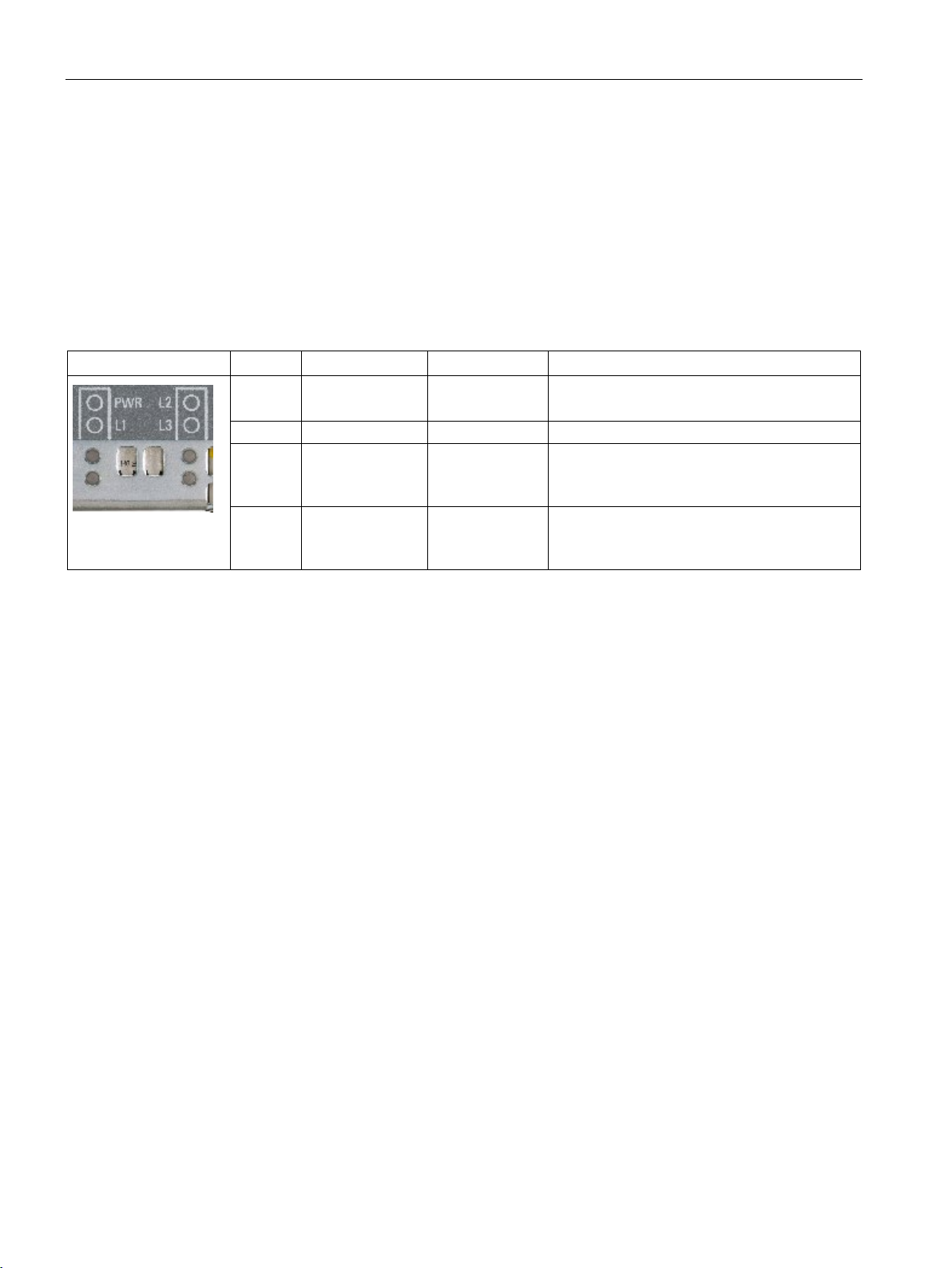
Description
2.3
LED display
Introduction
LED display
Status displays
LED
Meaning
LED
Description
GREEN
Supply voltage is applied.
RED
flashing GREEN
2.3 LED display
This section contains information explaining how the LED displays work. This means you
can make sure that the wireless LAN controller has started up completely.
PWR Power supply OFF
L1 - - L2 Battery display flashing RED
L3 RUN/STOP Flashing
YELLOW
Standby mode
Battery low (remaining life less than 1 month).
Battery empty.
System is starting up.
System running.
The L2 and L3 LEDs each flash at 1 second intervals.
If the L2 and L3 LEDs flash yellow together at an interval of 2 seconds, an upgrade or the
import of a configuration following an upgrade is being performed.
SCALANCE WLC711
16 Getting Started, 04/2016, C79000-G8976-C269-07
Page 17

3
3.1
Sequence
Step 1 - Prior to configuration
Data
Note
PNIO
For complex plants requiring PROFINET IO communication, stand
points with iPCF support are recommended.
Voice
Captive portal
Step 2 - Setting up the network
Below you will find an overview of the best way to configure access points.
Decide which WLAN service you want to use. The following are available:
●
This WLAN service is recommended if your WLAN is used mainly for normal data traffic,
for example intranet. This WLAN service can be suitable for PROFINET IO if WLAN
clients move within the range of one access point (no roaming of WLAN clients between
several access points). Possible topologies for the WLAN service are as follows:
– Bridge at AP (requirement for PNIO)
– Bridge at WLC
– Routed
●
This WLAN service is recommended if your WLAN is used mainly for voice and video
communication, for example VoIP.
Possible topologies for this WLAN type are as follows:
– Bridged at WLC
– Routed
●
With this WLAN service, you can set up a WLAN specifically for guests.
-alone access
Make sure that the external servers such as DHCP and RADIUS are available and
adequately configured. Make sure that the data port between the Industrial Ethernet switch
(IE Switch) and WLC and the IE switch and APs have the identical subnet configuration.
SCALANCE WLC711
Getting Started, 04/2016, C79000-G8976-C269-07
17
Page 18

Getting started
Step 3 - Installing hardware
3.1 Sequence
Install the SCALANCE Industrial Wireless LAN controller and the access points. You will find
further information in the compact operating instructions SCALANCE WLC711.
SCALANCE WLC711
18 Getting Started, 04/2016, C79000-G8976-C269-07
Page 19
Getting started
3.2
Logon
Prerequisite
Calling up the logon page
Note
Display of a security message
If a security message is displayed in the Web browser, confirm this to continue the download
of the Web page. The secu
It is possible to install your own certificate. You will find more detailed information in the
SCALANCE WLC711 user guide.
3.2 Logon
To log on with the WBM, a connection must exist between the management port ("admin"
interface) of the WLC and the configuration PC.
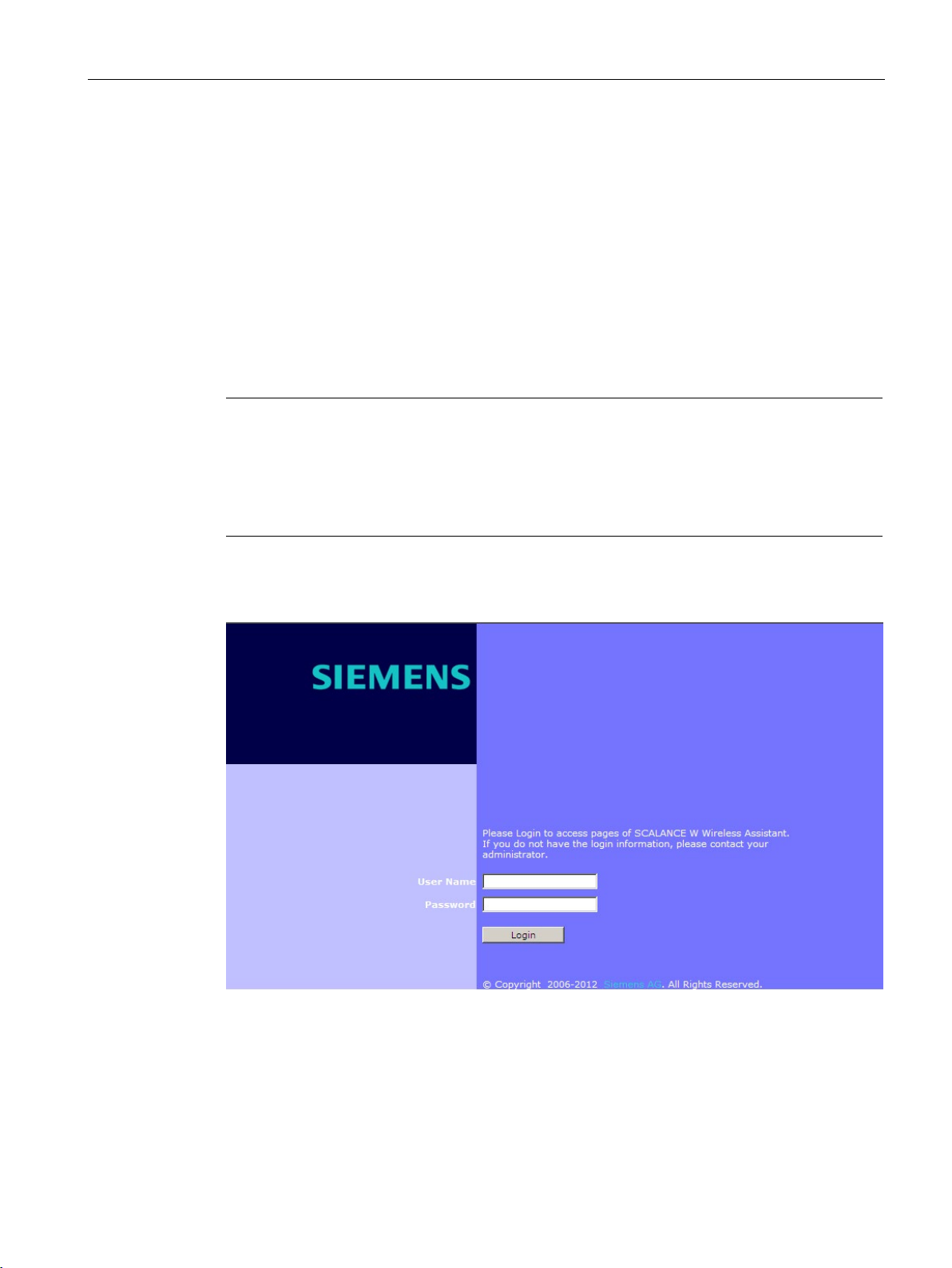
To call up the logon page, open a Web browser and enter the default IP address
https://192.168.10.1:5825 in the address line.
rity message results from the pre-installed, self-signed certificate.
This default IP address can be changed using the WBM. The logon page of the WBM
SCALANCE Industrial Wireless LAN controller and access points opens:
Figure 3-1 Logon page
SCALANCE WLC711
Getting Started, 04/2016, C79000-G8976-C269-07
19
Page 20

Getting started
Initial logon
Access protection of the system - changing passwords
Entering the wrong user name or password
3.2 Logon
Default user data is set in the factory. When you log on the first time, follow the steps below:
1. Enter the user name
2. Enter the password
admin in the "User Name" input box.
abc123 in the "Password" input box.
3. Click the "Login" button. The page for basic configuration with the wizard opens.
When you have completed the basic configuration the start page of the WBM SCALANCE
Industrial Wireless LAN controller and access points is displayed immediately after a new
logon.
We recommend that you protect the system from unauthorized access. To do this, change
the factory-set default administrator password. The procedure is described during basic
configuration with the wizard.
If you enter an unconfigured user name or an incorrect password, an error message is
displayed.
SCALANCE WLC711
20 Getting Started, 04/2016, C79000-G8976-C269-07
Page 21
Getting started
3.3
Shutting down and turning off
Introduction
Note
Data loss
Remember that data on the hard disk can be lost if you do not shut down the SCALANCE
WLC711 correctly. Make sure that you
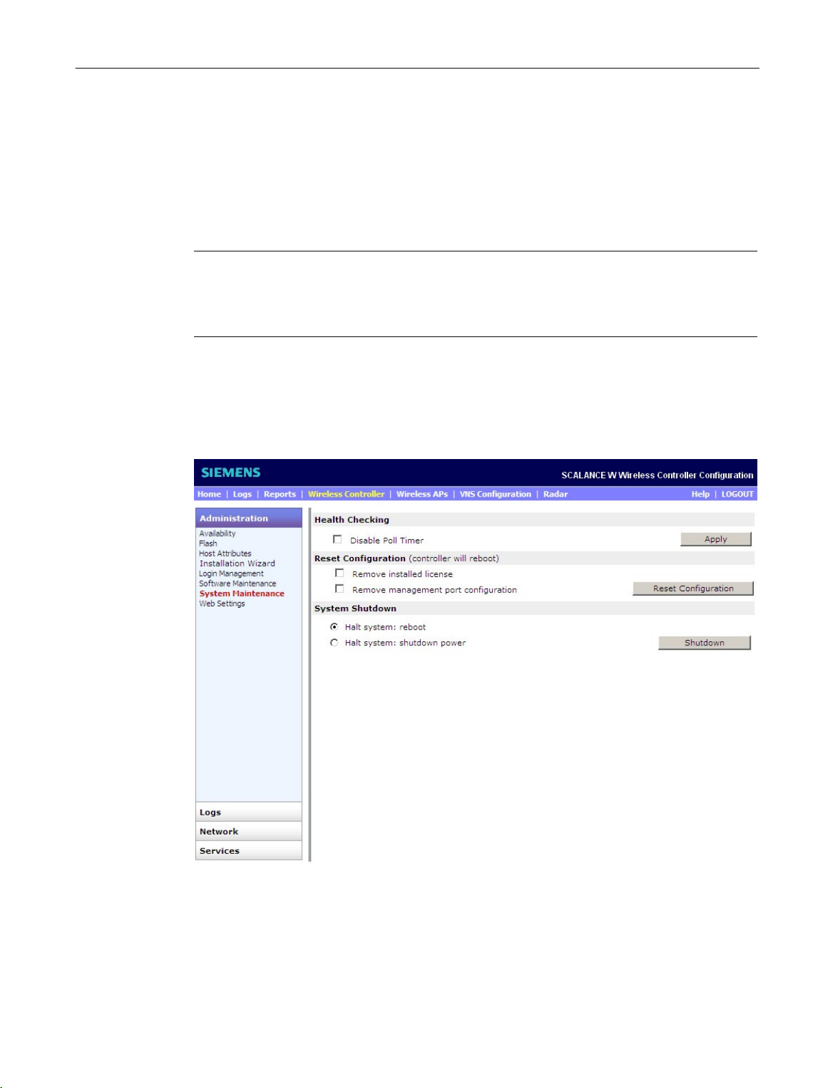
"System Maintenance" configuration page
3.3 Shutting down and turning off
To avoid loss of data, it is advisable to shut down and turn off the SCALANCE WLC711
using the operator interfaces.
use the procedure in this section.
To open the configuration page, select the "Wireless Controller > Administration > System
Maintenance" menu command. The following window opens:
Figure 3-2 "System Maintenance" configuration page
SCALANCE WLC711
Getting Started, 04/2016, C79000-G8976-C269-07
21
Page 22

Getting started
Procedure
Halt system: reboot
Halt system: shutdown power
3.3 Shutting down and turning off
To turn off the SCALANCE WLC711 correctly, follow the steps below:
1. Select from the following options in the "System Shutdown" section:
–
The system is shut down and restarted.
–
The system is shut down safely. All services and applications are stopped.
2. To shut down the system with the APs that belong to it and that are connected to it, click
the "Shutdown" button. A warning appears. To confirm the action, click the "Yes to
continue" button.
As an alternative, you can also shut down the WLC with CLI commands. You will find further
information in the manual SCALANCE WLC711 CLI Reference Guide.
SCALANCE WLC711
22 Getting Started, 04/2016, C79000-G8976-C269-07
Page 23

4
Introduction
Note
Reconfiguration of the network topology with the wizard is not possible.
You cannot reconfigure the network topology with the wiza
system reset. You can only modify the network topology later using the "Wireless Controller
> Topologies" menu command.
After you log on the first time, the WBM provides you with a wizard for the basic
configuration of the WLC.
You can call up the wizard at any time using the "Wireless Controller > Installation Wizard"
menu command.
rd, but only configure following a
SCALANCE WLC711
Getting Started, 04/2016, C79000-G8976-C269-07
23
Page 24
Basic configuration with the wizard
Example
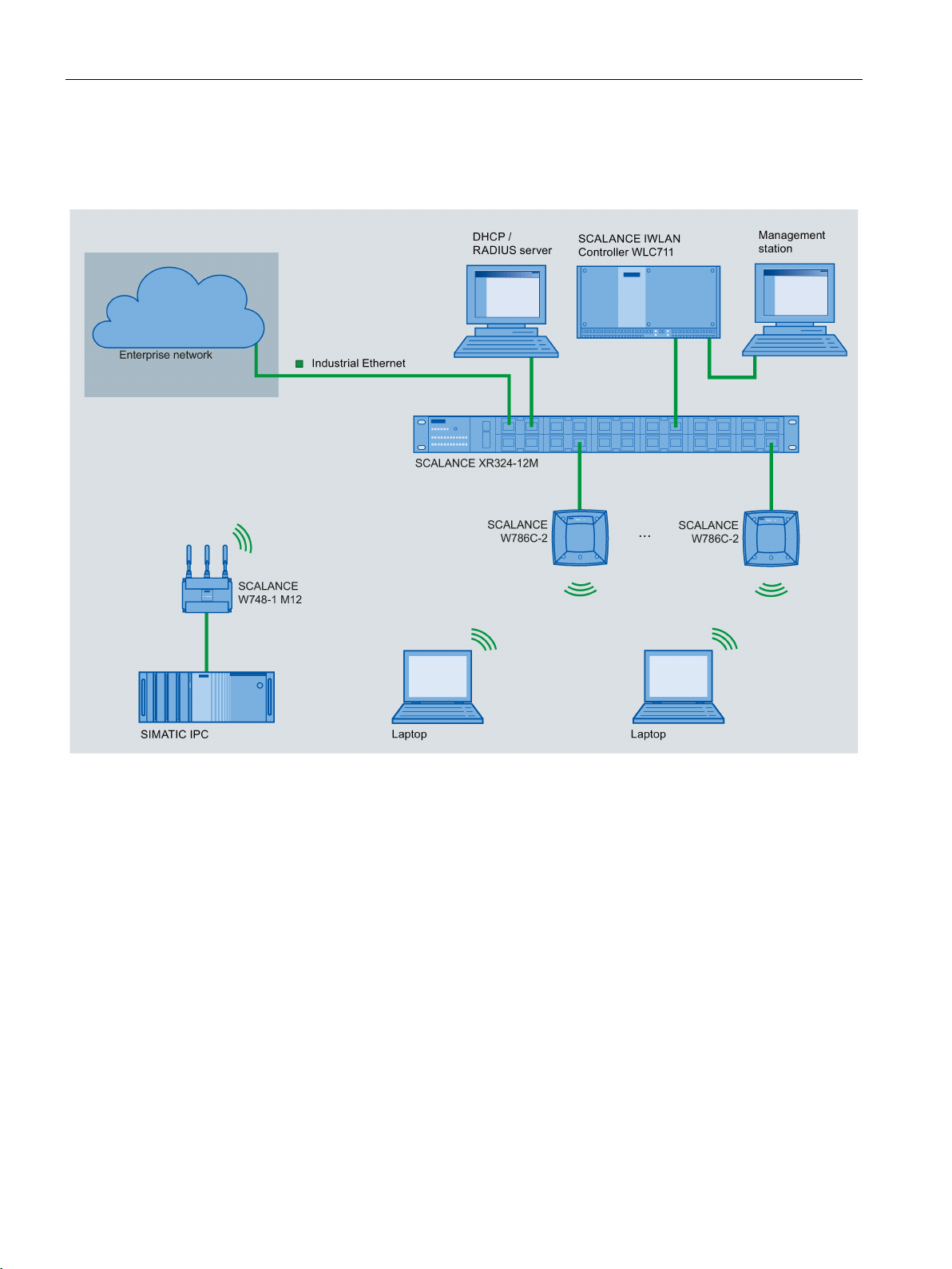
The following graphic shows you a typical WLC-based configuration of a WLAN:
Figure 4-1 Example: Typical WLC-based configuration of a WLAN
SCALANCE WLC711
24 Getting Started, 04/2016, C79000-G8976-C269-07
Page 25
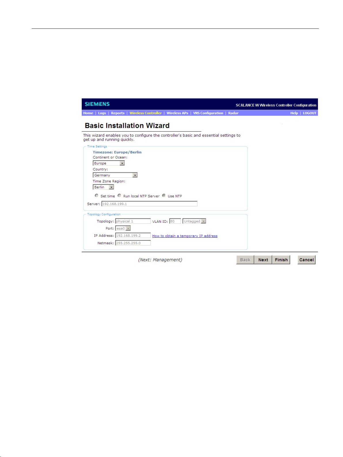
Basic configuration with the wizard
4.1
Procedure - "Basic Installation Wizard" page
"Basic Installation Wizard" configuration page
Time Settings
4.1 Procedure - "Basic Installation Wizard" page
When you log on for the first time, the following window opens:
Figure 4-2 "Basic Installation Wizard" configuration page
To use the basic installation with the wizard correctly, follow the steps below:
In this section, you configure the time zone of the WLC.
From the drop-down lists, select the continent or ocean, the country and the region of the
time zone in which the WLC is located.
SCALANCE WLC711
Getting Started, 04/2016, C79000-G8976-C269-07
25
Page 26

Basic configuration with the wizard
Meaning of the "Time Zone Region" options:
Set time
Run local NTP Server
Use NTP
Topology Configuration
Topology
VLAN ID
Note
VLAN ID 1 is the default internal VLAN ID of the WLC and can therefore only be used after
conf
VLAN ID and Multicast Support".
4.1 Procedure - "Basic Installation Wizard" page
●
With this option, you set the year, the month, the day, the minutes and the seconds
manually using drop-down lists.
●
If you select this option, the WLC functions as an NTP server and provides other devices
with the opportunity of synchronizing their time with the time of the WLC.
●
If you select this option, an external NTP server is used for time-of-day synchronization.
In this input box, enter the IP address of an NTP time server that has a connection to the
network.
In this section, you configure the physical interface of the WLC that is assigned as data port.
Enter the required values in the input boxes:
Using the assigned logical names, topologies are linked to a VNS (Virtual Network Service).
The wizard proposes the predefined name "Physical 1". On completion of the basic
configuration, you can change the name using the "Wireless Controller > Topologies" menu
command.
A VNS is the logical linking of all components required to operate a WLAN. This includes:
● WLAN service
● Policy
● Class of Service
● Topology
Using the VLAN ID, you assign a broadcast domain to the WLC data port. In this area, the
VLAN ID is configured for the WLC. Make sure that the data port of the WLC, the access
points and the connecting network are assigned to the same broadcast domain. Use the
following range for the VLAN ID: 1 to 4094. Enter the VLAN ID you want to work with in the
"VLAN ID" input box.
iguration. You will find further information in the user guide, section "Setting Up Internal
SCALANCE WLC711
26 Getting Started, 04/2016, C79000-G8976-C269-07
Page 27

Basic configuration with the wizard
Tagged
Untagged
"Port" drop-down list
IP Address
Netmask
4.1 Procedure - "Basic Installation Wizard" page
Select the required option from the drop-down list:
●
If you want to forward tagged packets, select this option. Make sure that your devices are
capable of reading tagged packets.
●
If you want to forward untagged packets, select this option. This is the default selection.
From the drop-down list, select the data port "esa0" of the WLC.
Enter the IP address of the data port "esa0" of the WLC. Use the IP address range of your IP
subnet.
If you require information about obtaining a temporary IP address, click on the link "How to
obtain a temporary IP address".
Enter the netmask of the data port "esa0" of the WLC.
To move to the next page of the wizard, click the "Next" button.
SCALANCE WLC711
Getting Started, 04/2016, C79000-G8976-C269-07
27
Page 28
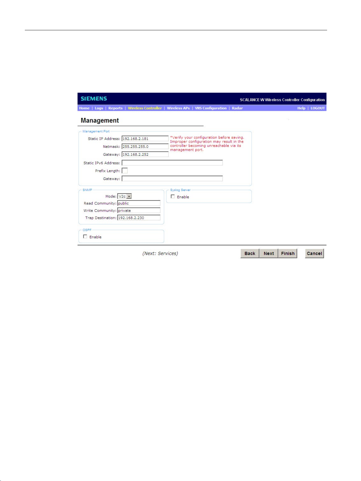
Basic configuration with the wizard
4.2
Procedure - "Management" page
"Management" configuration page
Management port
IP Address
Netmask
4.2 Procedure - "Management" page
Figure 4-3 "Management" configuration page
In this section, you configure the management port of the WLC via which the configuration
data is transferred.
If necessary, adapt the factory setting to your network environment:
Shows the IP address of the management port of the WLC.
To separate the range of the network from the range of the hosts, the corresponding subnet
mask of the IP address is displayed. Enter the netmask of the data port "esa0" of the WLC.
SCALANCE WLC711
28 Getting Started, 04/2016, C79000-G8976-C269-07
Page 29

Basic configuration with the wizard
Gateway
Note
Check that the contents are correct
Check that your entries are corre
configuration, it will not be possible to establish the connection to the SCALANCE Industrial
Wireless LAN access point.
SNMP
"Mode" drop-down list
OFF
V2c
V3
Note
In this version, some SNMP objects only have
4.2 Procedure - "Management" page
Shows the standard gateway of the network.
ct before saving the settings. If there are errors in the
In this section, the monitoring, control and error detection of the network components is set
using the "Simple Network Management Protocol".
SNMP is a network protocol with which network components can be monitored and
controlled from a central station. The following settings are available:
Select from the following options:
●
If you select this option, you disable SNMP.
●
If you select this option, you allow SNMP version 2. The following input boxes appear for
SNMP communication:
– Read Community
Enter the password to be used for the read mode of SNMP communication.
– Write Community
Here, enter the password to be used for the write mode of SNMP communication.
– Trap Destination
Enter the IP address of the server you are using that will receive the SNMP messages
as network manager.
●
If you select this option, you allow SNMP version 3. Following the basic installation, you
can create users and configure them manually with the " Wireless Controller > SNMP"
menu command.
read permissions.
SCALANCE WLC711
Getting Started, 04/2016, C79000-G8976-C269-07
29
Page 30

Basic configuration with the wizard
Syslog server
OSPF
Port
Area ID
4.2 Procedure - "Management" page
The syslog server is configured in this section.
Syslog is a protocol used for the transfer of event notification messages via networks.
To use the syslog protocol for the WLC, select the "Enable" check box. The "IP Address"
input box appears in which you enter the IP address of the syslog server.
In this section, you enable the "Open Shortest Path First" protocol. OSPF is a dynamic
routing protocol for medium sized to large IP networks. This protocol allows data streams to
be split up over various routes. If you select OSPF, the WLC uses "Dynamic Route
Selection". This means that subnets are set up.
Select the "Enable" check box. The following options appear:
Click on the topology name of the WLC you want to configure.
Define the area of OSPF. If necessary, adapt the factory setting to your network
environment.
To move to the next page of the wizard, click the "Next" button.
SCALANCE WLC711
30 Getting Started, 04/2016, C79000-G8976-C269-07
Page 31
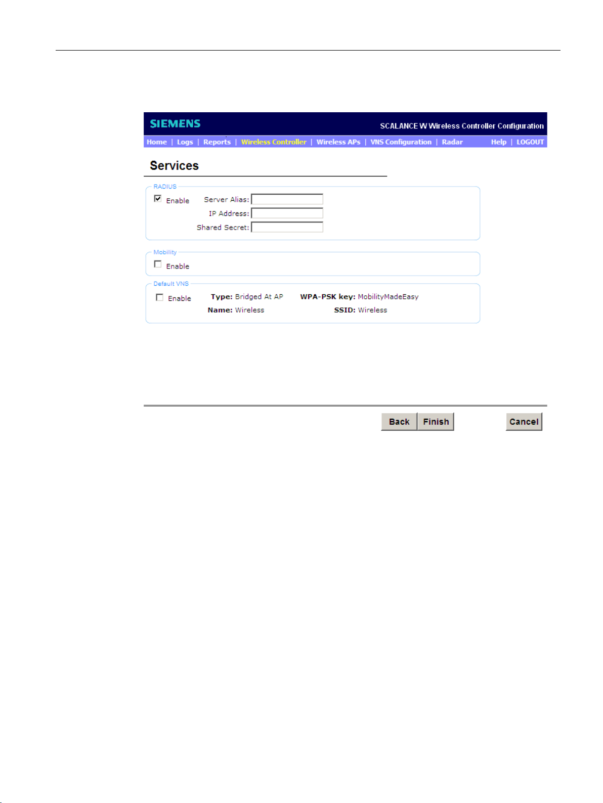
Basic configuration with the wizard
"Services" configuration page
RADIUS
Server Alias
IP Address
Shared Secret
4.2 Procedure - "Management" page
Figure 4-4 "Services" configuration page
In this section, you enable the "Remote Authentication Dial In User Service" protocol
(RADIUS). The authentication and authorization is managed by a RADIUS server that is
configured in this section.
Select the "Enable" option. The following input boxes appear:
●
Name the RADIUS server by entering the name.
●
Enter the IP address of the RADIUS server.
●
Enter the password required for the connection between the WLC and the RADIUS
server.
SCALANCE WLC711
Getting Started, 04/2016, C79000-G8976-C269-07
31
Page 32

Basic configuration with the wizard
Mobility
Note
To allow WLCs to communicate with each other, at least one mobility manager is required.
The other WLCs act as mobility agents.
If t
manager as the NTP server. If the WLC is configured as the mobility manager, the "Run
local NTP server" option must be enabled so that the mobility agents can use the
server of the mobility manager.
"Role" radio button
"Port" drop-down list
"Manager IP" input box
Default VNS
Type: Bridged at AP
WPA-PSK Key: MobilityMadeEasy
Name: Wireless
SSID: Wireless
4.2 Procedure - "Management" page
In this section, you enable the "Mobility" feature. This feature allows WLAN devices, for
example a laptop, to roam between different WLCs seamlessly within different wireless APs.
Select the "Enable" check box. A message will inform you that the Network Time Protocol
(NTP) is necessary for mobility. You will be prompted to allow NTP.
The dialog for further configuration opens.
he WLC is configured as a mobility agent, it acts as an NTP client and uses the mobility
local NTP
●
Select the role of mobility manager or mobility agent for the WLC. Select one WLC as
mobility manager in the network and all others as mobility agents.
●
Select the interface of the WLC that will be used for communication between the mobility
manager and mobility agent. Make sure that the selected interface in the network is
capable of routing.
●
If the WLC was configured as a mobility agent, enter the IP address of the mobility
manager in the input box.
A virtual network service is the logical linking of all attributes necessary for a WLAN. In this
section, you enable the standard VNS parameters that can then be configured later with the
"VNS Configuration" menu command.
Meaning of the default values:
●
Communication is direct via the AP and not via the WLC.
●
The password of the WPA-PSK is "MobilityMadeEasy". To increase the security of the
VNS, we recommend that you change this default password.
●
The name of the VNS is "Wireless"
●
The name of the Service Set Identifier of the VNS is "Wireless".
SCALANCE WLC711
32 Getting Started, 04/2016, C79000-G8976-C269-07
Page 33
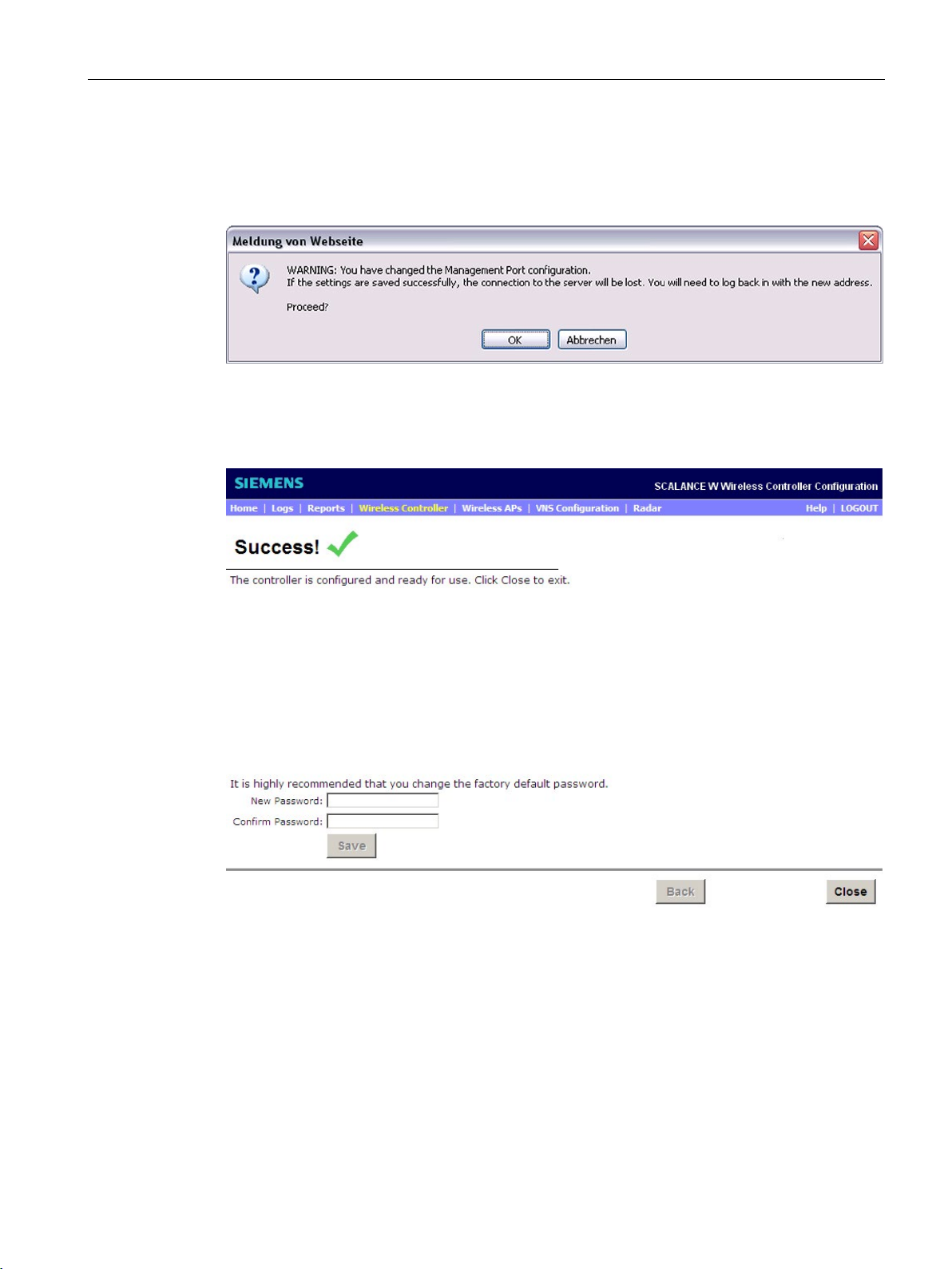
Basic configuration with the wizard
"Success" configuration page (wizard completed successfully)
4.2 Procedure - "Management" page
To complete the installation, click the "Finish" button.
A warning message is displayed because you want to change settings of the management
port. To confirm the changes, click the "OK" button.
Figure 4-5 Warning: Management port
Figure 4-6 "Success" configuration page (wizard completed successfully)
SCALANCE WLC711
Getting Started, 04/2016, C79000-G8976-C269-07
33
Page 34

Basic configuration with the wizard
Note
Changing the password
We recommend that you change the password. For optimum security, a password should
have following features:
•
•
. Numbers and
•
4.2 Procedure - "Management" page
You have configured the WLC and it can be used. If you do not want to make any other
changes, click the "Close" button.
A length of 8 to 24 characters
Different characters. You can use special characters except for ` ' " \ :
upper and lower case characters.
Do not use sequences of characters, for example "12" or "ab".
Enter the new password in the "New Password" input box. Confirm the new password by
entering it again in the "Confirm Password" input box. To store your new password, click the
"Save" button.
To close the page, click the "Close" button.
You have now completed the wizard successfully.
Once you have completed the basic configuration, you will be logged off because the WBM
loads the new settings. If the time zone was changed, the WLC is automatically restarted.
Log on again with the WBM with the updated settings.
SCALANCE WLC711
34 Getting Started, 04/2016, C79000-G8976-C269-07
Page 35
5
5.1
Commissioning access points
Prerequisite
Procedure
To establish a connection between a SCALANCE Industrial Wireless LAN controller and an
access point, the access point must be connected to the IE network.
On the "Topology" configuration page, set the network topology of the SCALANCE Industrial
Wireless LAN controller. If you configure and save these settings, a connection can be
established between the SCALANCE Industrial Wireless LAN controller and the access
point.
To open the configuration page, select the "VNS Configuration > Topologies" menu
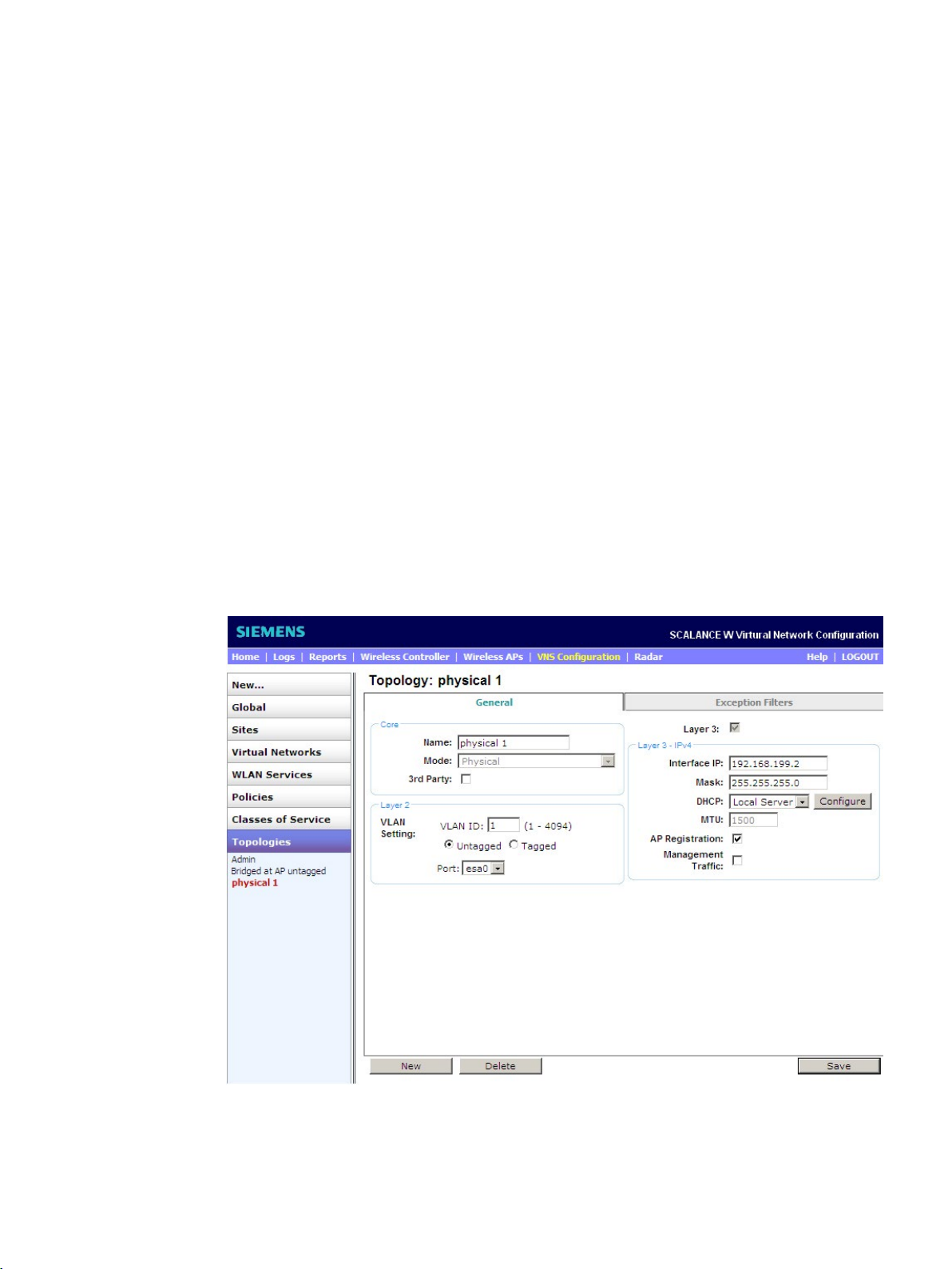
command. From the "Topologies" list on the left, select the predefined type "physical 1". The
"Topology" window opens:
Figure 5-1 Configuration of the network topology
SCALANCE WLC711
Getting Started, 04/2016, C79000-G8976-C269-07
35
Page 36

Managing access points
Example: Configuration of the network topology "physical 1"
Core
"Name" input box
"Mode" drop-down list
"3rd Party" check box
Layer 2
"VLAN ID" input box
Radio buttons
"Port" drop-down list
5.1 Commissioning access points
"Physical 1" is a topology based on the data port of the SCALANCE Industrial Wireless LAN
controller. It is responsible for the layer 2 and layer 3 properties. In the "General" tab, you will
see the sections "Core", "Layer 2" and "Layer 3" and these are explained below.
In this section, you configure the basic properties of the topology.
●
Here, enter the logical name of the topology.
●
Select "Physical" from the "Mode" drop-down list.
●
If you want to connect access points that are not intended for operation with the WLC,
enable this check box. You will find information about configuring these access points in
the SCALANCE WLC711 User Guide.
In this section, the settings you made with the wizard in the basic configuration are
displayed.
●
The VLAN ID is required for the communication between the WLC and the access points
throughout the connecting network. In this area, the VLAN ID is configured for the WLC.
Make sure that the WLC, the access points and the connecting network are assigned to
the same broadcast domain. Use the following range for the VLAN ID: 2 to 4094. Enter
the required VLAN ID you want to use in the "VLAN ID" input box.
●
Select the required option with the radio buttons:
– Tagged
If you want to forward tagged packets, select this option. Make sure that your devices
are capable of reading tagged packets.
– Untagged
If you want to forward untagged packets, select this option. This selection is made as
default.
●
From the drop-down list, select the data port "esa0" of the SCALANCE Industrial Wireless
LAN controller.
SCALANCE WLC711
36 Getting Started, 04/2016, C79000-G8976-C269-07
Page 37
Managing access points
Layer 3 - IPv4
"Interface IP" input box
"Mask" input box
"DHCP" drop-down list
5.1 Commissioning access points
In this section, you configure the IP settings of the topology.
●
Here, you define the IP address of the topology.
●
Enter the IP address in the net mask.
●
DHCP (Dynamic Host Configuration Protocol) is a method for automatic assignment of IP
addresses. It has the following properties:
– DHCP can be used both when starting up a device and during ongoing operation.
– The assigned IP address remains valid only for a particular time known as the "lease
time". Once this period has elapsed, the client must either request a new IP address
or extend the lease time of the existing IP address.
– There is normally no fixed address assignment; in other words, when a client requests
an IP address again, it can receive a different address from the previous address.
From the "DHCP" drop-down list, select the following options for the DHCP settings of the
access points:
– Local server
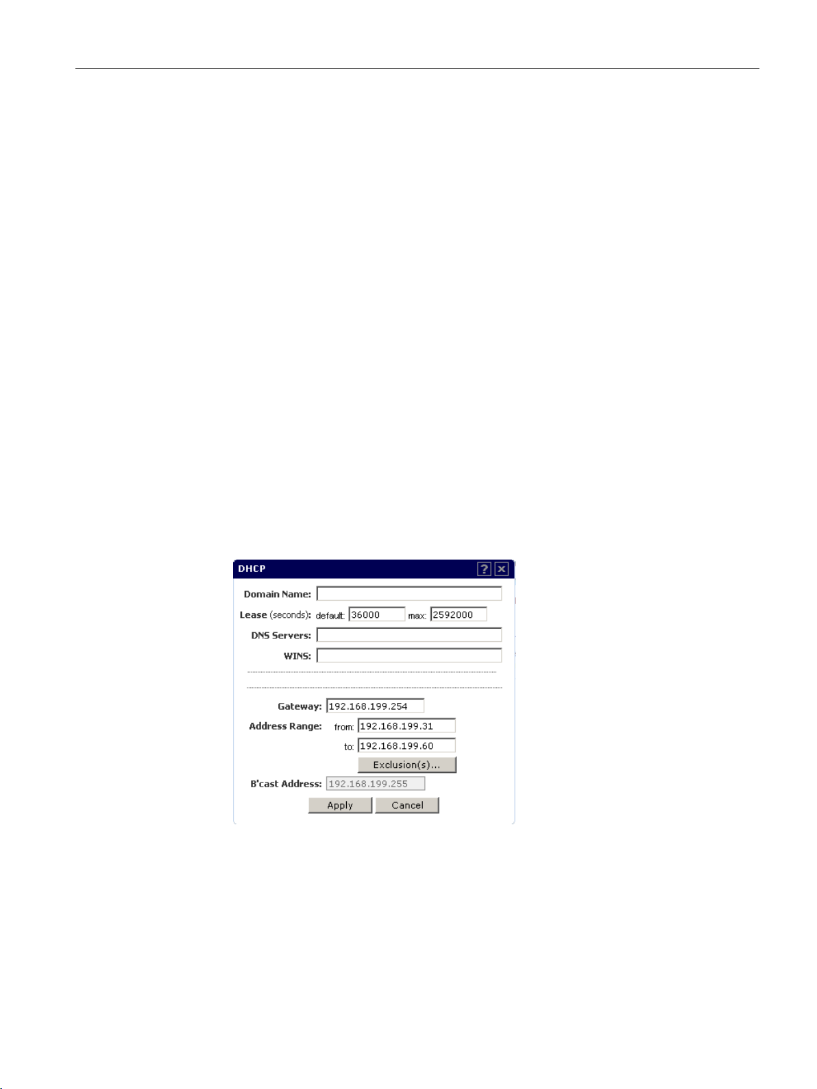
If you select this option, the "esa0" topology becomes the DHCP server. To configure
the DHCP server, click the "Configure" button. The following dialog box opens:
Figure 5-2 Configuring the DHCP server dialog box
The default values already entered can be retained. Enter the IP address of the router
in the "Gateway" input box. No other boxes need to be configured. If you nevertheless
want to configure these boxes, you will find further information in the SCALANCE
WLC711 User guide. Save your configuration.
– None
If a DHCP server is already in your network, select this option.
SCALANCE WLC711
Getting Started, 04/2016, C79000-G8976-C269-07
37
Page 38

Managing access points
"MTU" display box
"AP Registration" radio button
"Management Traffic" radio button
Buttons
New
Delete
Result
5.1 Commissioning access points
●
The Maximum Transmission Unit (MTU) defines the maximum transmission unit or
maximum packet size of a protocol for this topology. The fixed value is 1500 bytes for
physical topologies and is not changed.
●
Enable the check box so that the AP can register with the SCALANCE Industrial Wireless
LAN controller.
●
Select the check box so that you can configure the WLC via the data port (management).
To store your settings, click the "Save" button. The access point can now connect to the
SCALANCE Industrial Wireless LAN controller.
To configure new topologies, the following buttons are available:
●
With this button, you create a new topology.
●
With this button, you delete the selected topology. Select the topology and then click the
"Delete" button.
If you have completed everything correctly, the access points log on automatically and are
shown in the wireless list available with the "Wireless APs" menu command. From this point
onwards, the APs can be configured singly or in groups.
SCALANCE WLC711
38 Getting Started, 04/2016, C79000-G8976-C269-07
Page 39
Managing access points
5.2
Registering access points
"AP Registration" configuration page
Manual
Automatic
Procedure
5.2 Registering access points
This section explains how to register access points with the WLC. You configure the security
properties and the type of registration of the APs. You can register access points in two
different ways:
●
Before you connect the AP, first enter the serial number of the AP in the WBM. When the
AP is later connected to the network, this is registered immediately. How to register the
AP manually is explained in the SCALANCE User Guide in the section "Adding and
Registering a Wireless AP Manually".
●
How to register APs automatically is explained in detail on the following pages.
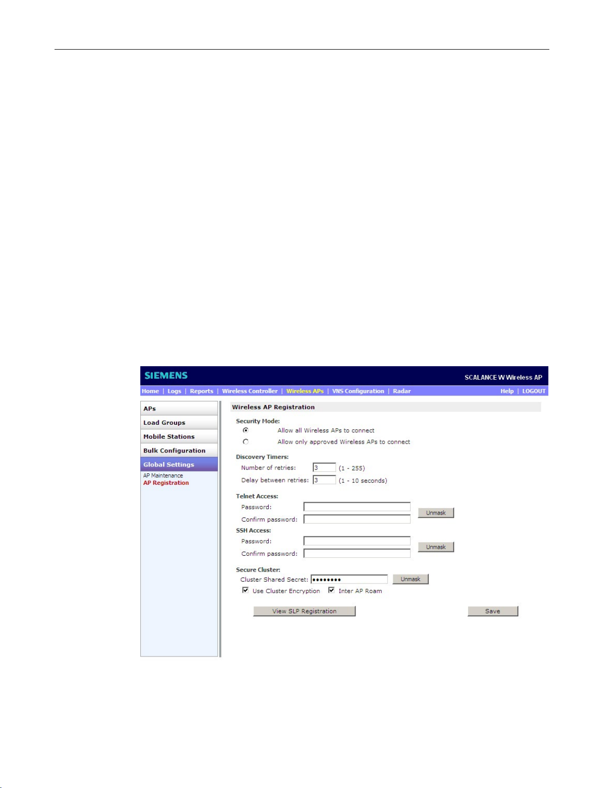
To open the "AP Registration" configuration page, select the "Wireless APs > Global
Settings > AP Registration" menu command. The following window opens:
Figure 5-3 Wireless APs - AP Registration
SCALANCE WLC711
Getting Started, 04/2016, C79000-G8976-C269-07
39
Page 40

Managing access points
Security Mode
Allow all Wireless APs to connect
Note
Security Mode
It is advisable to enable the option "Allow all Wireless APs to connect" during the initial
configuration of the network. This gives you the option of registering several APs at
the same time and improving efficiency.
When you have comp
enable the option "Allow only approved Wireless APs to connect". This means that
third
WLC711" User Guide.
Allow only approved Wireless APs to connect
Note
Access points can then only log on su
licenses available. Remember that APs themselves take up licenses when they are in
the "Pending" status.
Discovery Timers
Number of retries
Delay between retries
5.2 Registering access points
To configure the security mode for the WLC, enable one of the available radio buttons
according to your requirements:
●
– If the serial number of the AP is not known to the WLC, a new registration entry is
created automatically. The AP receives a default configuration.
– If the WLC knows the serial number of the AP, the WLC authenticates the AP based
on the existing registration entry and sends the existing configuration to the AP.
leted the initial configuration of the network, it is advisable to
-party devices cannot log on. You will find further information in the "SCALANCE
●
– If the serial number of the AP is not known to the WLC, a new registration entry is
created automatically and given the status "Pending". To allow the AP to receive
status changes, the WLC sends a minimum configuration to the AP. This minimum
configuration allows an existing connection to remain established. APs with the
"Pending" status cannot be configured and do not receive a default configuration until
they are given the "Approved" status.
– If the WLC recognizes the serial number of the AP, it authenticates the AP based on
the existing registration entry and sends the existing configuration to the AP.
ccessfully with a WLC if this has enough free
The parameters are set:
●
In the input box, enter the number of possible logon retries of the AP with the WLC.
●
In the input box, enter the delay between the logon retries in seconds.
If the AP does not reach the WLC, the AP attempts to register with the next WLC.
SCALANCE WLC711
40 Getting Started, 04/2016, C79000-G8976-C269-07
Page 41

Managing access points
SSH Access
Secure Cluster
Buttons
View SLP Registration
Save
"AP Default Settings" configuration page
"Save Settings" button
5.2 Registering access points
SSH means "Secure Shell" and it is a network protocol with which encrypted network
connections can be established. You require a password for this. Enter the password for
access to SSH in the "Password" input box. Confirm the password by entering it again in the
"Confirm password" input box.
The default values already entered can be retained.
You will find further information in the SCALANCE WLC711 User Guide in the section
"Configuring an AP Cluster".
The buttons have the following meanings:
●
The "Service Location Protocol" (SLP) is a protocol with which APs register with the WLC.
To obtain a view of the SLP registration process, click the button. A new window appears
in which the events of the registration process, for example of the IP addresses of the
WLC are shown.
●
To save your settings, click this button.
The section explains how to change the default settings.
When they register for the first time, the access points receive default settings that you can
change. It is also possible to specify the configuration of existing APs as a default
configuration.
How to change these default values is explained in the "Common Configuration" and
"W78xC" tabs. The other tabs are identical to the "W78xC" tab.
To go to the "AP Default Settings" configuration page, select the "Wireless AP > Bulk
Configuration > AP Default Settings" menu command.
To store your current settings, click the "Save Settings" button.
SCALANCE WLC711
Getting Started, 04/2016, C79000-G8976-C269-07
41
Page 42
Managing access points
Common Configuration
Static Configuration
Note
If the ranking list contains incorrect values, for example a non-existent IP address, the AP
will not find any WLCs.
5.2 Registering access points
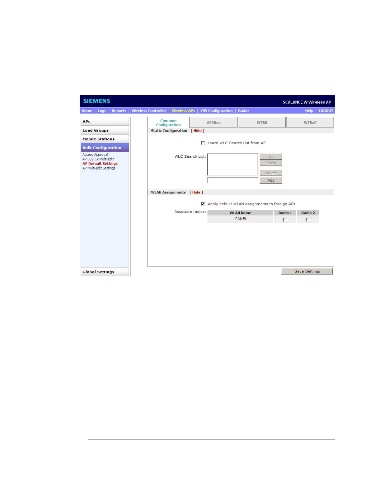
In this area, you set the use of the WLAN. From the "Bulk Configuration > AP Default
Settings" configuration page, select the "Common Configuration" tab. The following window
opens:
Figure 5-4 AP Default Settings - Common Configuration
Where necessary, adapt the setting to your requirements:
The following options can be selected:
● So that each AP accesses the ranking list "WLC Search List", deselect the "Learn WLC
Search List from AP" check box. For further information about how to add WLCs to the
ranking list and to sort the list, refer to section"Single configuration (Page 45)".
● If the AP should not access the ranking list "WLC Search List", select the "Learn WLC
Search List from AP" check box. This means that the AP uses and maintains its individual
ranking list.
● If the ranking list "WLC Search List " has no entries, the AP uses the "SLP
unicast/multicast" functions or "DHCP" to find a WLC.
SCALANCE WLC711
42 Getting Started, 04/2016, C79000-G8976-C269-07
Page 43
Managing access points
WLAN Assignment
W78xC
AP Properties
LLDP
5.2 Registering access points
In this area, you have the option of assigning Radio 1 and/or Radio 2 (wireless interface) for
each VNS in the list under "WLAN Name".
Enable or disable the "Radio 1" and/or "Radio 2" check box.
On this configuration page, you set the default values, for example the parameters of the
individual WLAN networks.
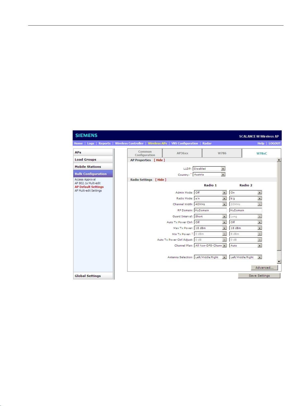
From the "Bulk Configuration > AP Default Settings" configuration page, select the "W78xC"
tab. The following window opens:
Figure 5-5 Wireless APs > Bulk Configuration - AP Default Settings
Where necessary, adapt the setting to your requirements.
Select your requirements from the drop-down lists:
With the "Link Layer Discovery Protocol", you can exchange device information, for example
the IP address between neighboring devices. Enable or disable the transfer of LLDP
information.
SCALANCE WLC711
Getting Started, 04/2016, C79000-G8976-C269-07
43
Page 44

Managing access points
Country
Radio Settings
5.2 Registering access points
Select the country where the AP is being operated.
Select the options for Radio 1 or Radio 2. You will find information about setting the Radio in
the section "Single configuration (Page 45)":
SCALANCE WLC711
44 Getting Started, 04/2016, C79000-G8976-C269-07
Page 45

Managing access points
5.3
Configuring access points
5.3.1
Single configuration
"All APs" configuration page
Buttons
Copy to Defaults
Reset to Defaults
Add Wireless AP
Save
5.3 Configuring access points
To open the "All APs" configuration page, select the "Wireless APs > APs > All" menu
command. With this page, you configure the access points individually. Note that a
configuration type can be used on more than one AP. For more detailed information, refer to
section "Multiple configuration (Page 58)".
Note the following buttons on this configuration page:
●
To save the configuration of the AP type as a default value in the WBM, click the "Copy to
Default" button.
●
To replace the current settings of the AP type with the default values, click the "Reset to
Default" button.
●
To register an AP manually, click the "Add Wireless AP" button.
●
To store your settings, click the "Save" button.
SCALANCE WLC711
Getting Started, 04/2016, C79000-G8976-C269-07
45
Page 46
Managing access points
AP Properties
"Serial #" display box
"Host Name" display box
"Name" input box
"Location" input box
5.3 Configuring access points
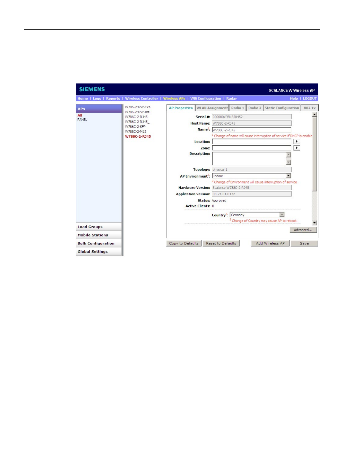
On the "APs > All" configuration page, select the "AP Properties" tab. The following window
opens:
Figure 5-6 Wireless APs > APs > All > AP Properties
From the middle list, select the access point you want to configure. In the "AP Properties"
tab, you can then view the settings of this AP and configure some of them.
Where necessary, adapt the setting to your requirements.
Displays the unique identification number of the access point. You will also find the
identification number printed on the access point.
This value is based on the AP type and the serial number and is used for assignment for the
DHCP server.
Enter a unique name for the AP that differs from other APs. The default value is the serial
number of the AP.
Enter the location of the AP.
SCALANCE WLC711
46 Getting Started, 04/2016, C79000-G8976-C269-07
Page 47

Managing access points
"Description" input box
"Topology" display box
"AP Environment" drop-down list
Note
Note that the maximum transmit power (Max Tx Power) depends on the selection
(indoor/outdoor) and that this can be restri
"Hardware Version" display box
"Application Version" display box
"Status" display
Approved
Pending
"Active Clients" display
"Country" drop-down list
Note
Remember that the maximum transmit power (Max Tx Power) depends on the country
selected and that it can be restricted by this.
5.3 Configuring access points
If required, enter a comment that describes the AP.
Shows the port of the topology of the AP selected during basic configuration.
From the drop-down list, specify whether the AP is in the building (indoor) or outside
(outdoor).
cted by this. Select the correct environment.
Shows the current hardware version of the AP.
Shows the current software version of the AP.
●
Shows that the AP is allowed to establish a connection to the WLC. You will find further
information in the SCALANCE WLC711 user guide.
●
The AP has not yet been recognized manually on the WLC and is not therefore allowed
to establish a connection to the WLC.
Shows how many end devices are currently connected to the AP.
From the drop-down list, select the country where the AP is being operated. If you change
the country, the AP is automatically restarted.
Select the correct country.
SCALANCE WLC711
Getting Started, 04/2016, C79000-G8976-C269-07
47
Page 48
Managing access points
Drop-down lists of the antenna types
WLAN Assignment
"WLAN Name" column
5.3 Configuring access points
Select the type for each antenna from the drop-down list. If you select "No Antenna", the AP
does not send any wireless signals. Note that this drop-down list is only available for APs
with external antenna connectors.
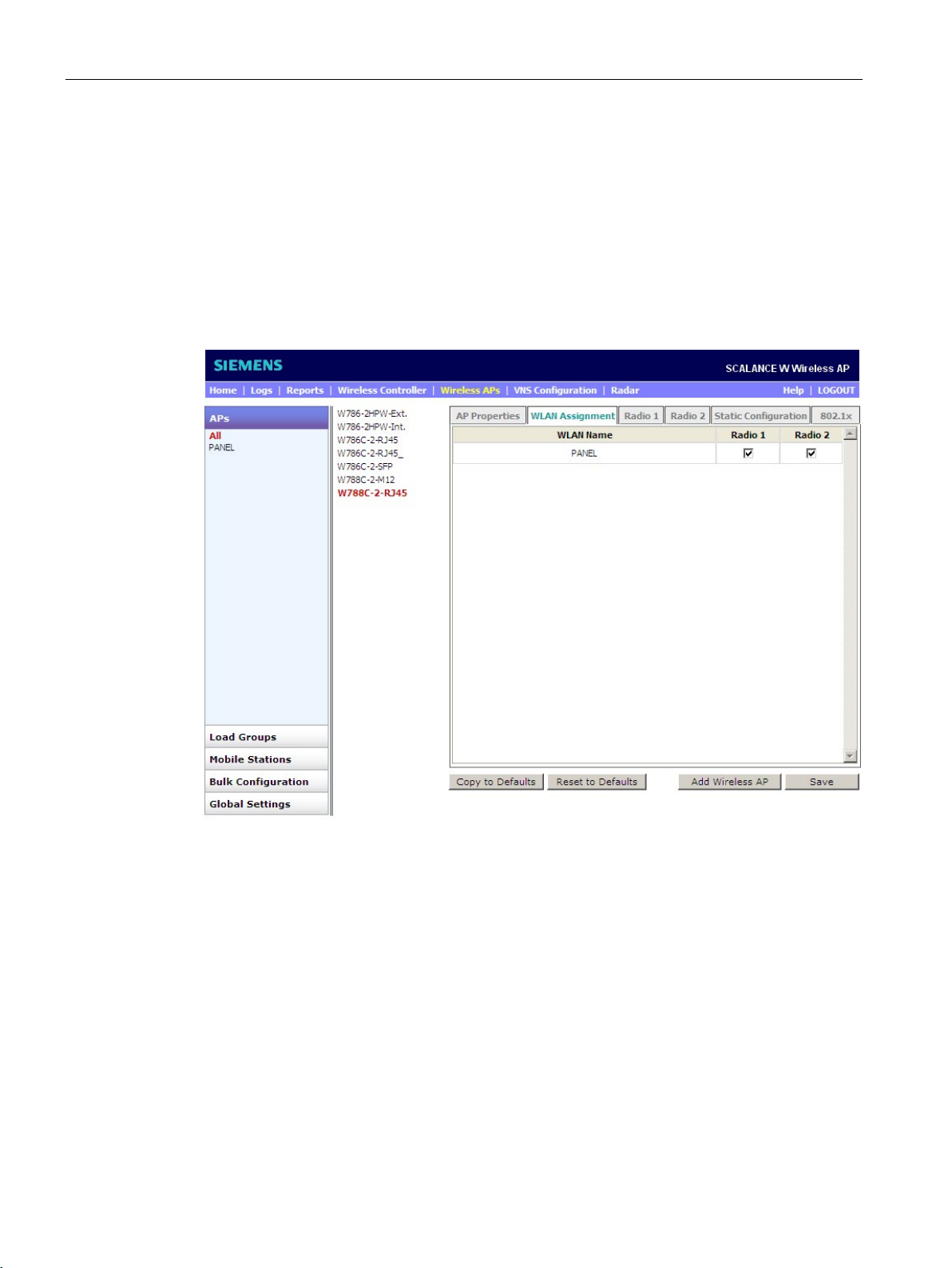
On the "APs > All" configuration page, select the "WLAN Assignment" tab. The following
window opens:
Figure 5-7 Wireless APs > APs > All > WLAN Assignment
From the middle list, select the access point you want to configure. In the "WLAN
Assignment" tab, you can establish an assignment between WLAN services and the WLAN
interfaces of the AP. Normally, Radio 1 corresponds to the IEEE standards 802.11a/n and
Radio 2 corresponds to the IEEE standards 802.11b/g/n. One exception to this is the
SCALANCE access point W786-2HPW.
Where necessary, adapt the setting to your requirements.
This column displays the configured WLAN services. Using the "VNS Configuration > WLAN
Services" menu command, you can configure WLAN services.
SCALANCE WLC711
48 Getting Started, 04/2016, C79000-G8976-C269-07
Page 49
Managing access points
"Radio 1" column
"Radio 2" column
Note
Selecting the IEEE standard 802.11
If you are not sure which WLAN standard your end devices (WLAN clients) support, select
both wireless frequencies
Note that the access point W786
WLAN Interface and therefore requires prior configuration. You will find further information in
the "SCALAN
Radio 1
5.3 Configuring access points
With Radio 1, select the frequency band that you wish to use for this WLAN service.
With Radio 2, select the frequency band that you wish to use for this WLAN service.
. Note that up to eight WLAN services can be configured per radio.
-2HPW can handle both wireless frequencies on each
CE WLC711" User Guide.
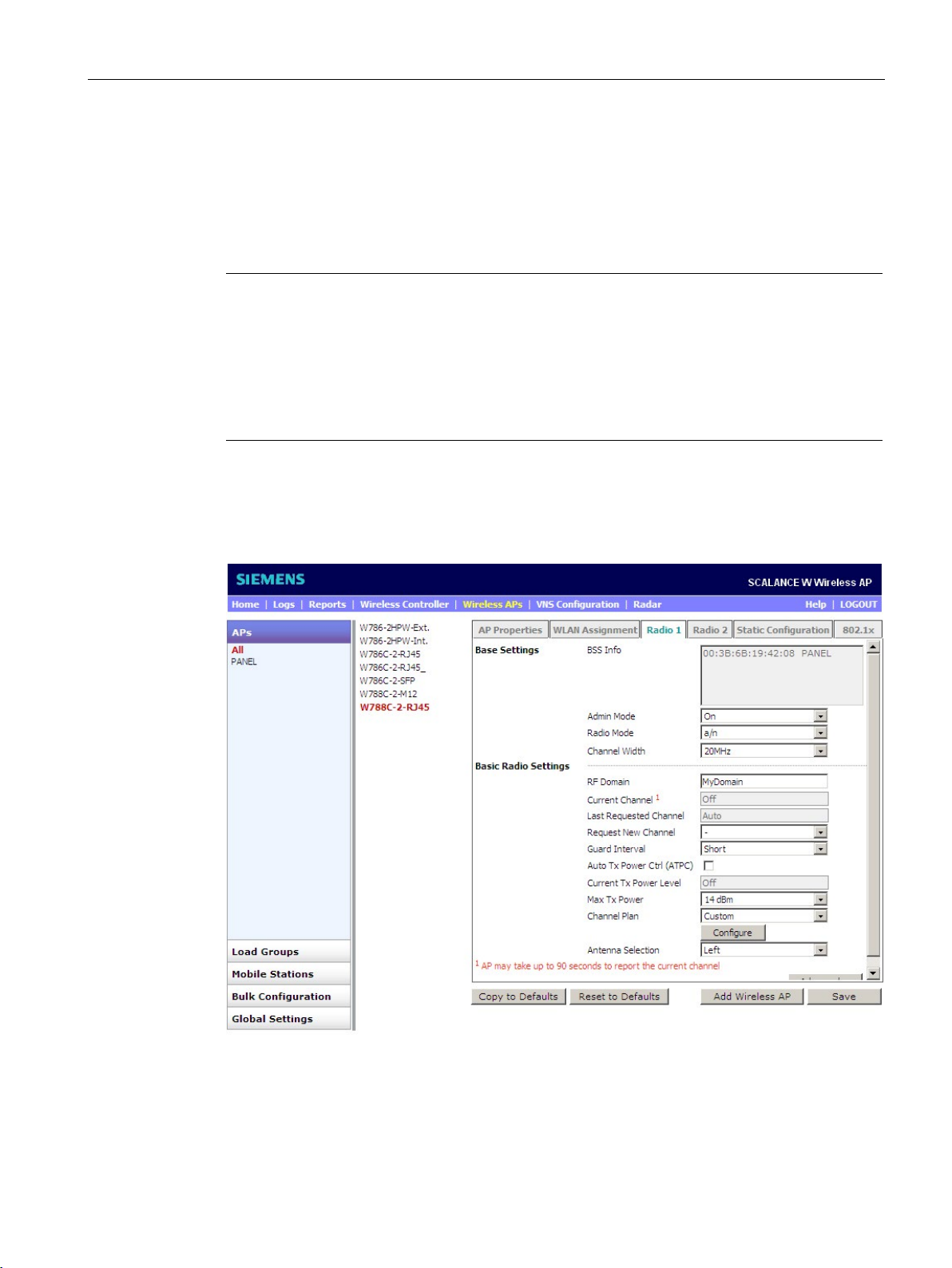
On the "APs > All" configuration page, select the "Radio 1" tab. The following window opens:
Figure 5-8 Wireless APs > APs > All > Radio 1 settings
From the middle list, select the access point you want to configure. Make the interfacespecific settings in the "Radio 1" tab.
SCALANCE WLC711
Getting Started, 04/2016, C79000-G8976-C269-07
49
Page 50

Managing access points
Base Settings
"BSS Info" display box
"Admin Mode" drop-down list
On
Off
"Radio Mode" drop-down list
"Channel Width" drop-down list
20MHz (downwards compatible with legacy modes IEEE standard 802.11a/h)
40MHz
Auto
5.3 Configuring access points
Where necessary, adapt the settings to your requirements.
BSS stands for "Basic Service Set". After configuring the WLAN services, the BSS displays
the MAC address of the AP for each WLAN. It also indicates which SSID of the WLAN was
assigned to which radio.
Select the following from the drop-down list:
●
To enable the radio, select "On".
●
To disable the radio, select "Off".
Select the required IEEE 802.11 standard from the drop-down list.
With IEEE standard 802.11n, data can be transferred via two directly neighboring channels.
The two 20 MHz channels are put together to form one channel with 40 MHz. This allows the
channel bandwidth to be doubled and the data throughput to be increased. If the radio
modes "n-strict" or "a/n" were selected, you can set the bandwidth.
Select the following from the drop-down list:
●
To disable channel bonding, select "20 MHz":
●
To enable channel bonding, select "40 MHz":
– The configured channel and the neighboring channel above it are used if the client
– If the client does not support channel bonding, the bandwidth is automatically reduced
●
supports channel bonding.
to 20 MHz. This means that IEEE 802.11n can also communicate with IEEE
802.11a/b/g clients.
To enable or disable channel bonding automatically, select "Auto". The bandwidth then
changes automatically between 20 MHz and 40 MHz depending on the load of the
expansion channel. If the expansion channel is under too much load and exceeds a
defined value of the 40 MHz range, channel bonding is automatically disabled.
SCALANCE WLC711
50 Getting Started, 04/2016, C79000-G8976-C269-07
Page 51

Managing access points
Basic Radio Settings
"RF Domain" input box
"Current Channel" display box
"Last Requested Channel" display box
"Request New Channel" drop-down list
"Guard Interval" drop-down list
Long
Short
"Auto Tx Power Ctrl (ATPC)" check box
"Current Tx Power Level" display box
"Max Tx Power" drop-down list
"Min Tx Power" drop-down list
5.3 Configuring access points
To identify a group of APs, an RF domain can be configured as an option.
Write a character string that uniquely identifies a group of APs. The maximum length of this
character string must not exceed 16 characters.
Shows which channel the AP is on.
Depending on the setting, this display depends on the "Request New Channel" function and
shows the last requested channel.
From the drop-down list, select the channel to be used for communication between the AP
and end device.
Channel bonding bonds the primary channel (20 MHz) with an expansion channel. With
"Up", the expansion channel is positioned 20 MHz above and with "Down" 20 MHz below the
primary channel. Remember that the available selection for channel bonding depends on the
"Request New Channel" selection.
The guard interval specifies how much time should elapse between sending two symbols. If
a 40 MHz channel was selected, select the following properties:
●
Select this option if 800 ns should elapse between sending two symbols.
●
Select this option if 400 ns should elapse between sending two symbols. This option is
suitable only for clients that support the IEEE standard 802.11n.
If you enable this check box, the AP automatically regulates its transmit power between Max
Tx Power and Min Tx Power.
Shows the current transmit power.
This setting depends on the selected country. Select the suitable maximum transmit power.
Select the suitable minimum transmit power.
SCALANCE WLC711
Getting Started, 04/2016, C79000-G8976-C269-07
51
Page 52

Managing access points
"Auto Tx Power Ctrl Adjust" drop-down list
"Channel Plan" drop-down list
All Channels
Custom
All Non-DFS Channels
"View" button
Note
Available channels
The number of channels depends on the selected country and the selected IEEE standard
802.11.
In the 2.4 GHz frequency band (IEEE standard 802.11 b/g), 13 or 11 (USA only) channels
can be selected.
"Antenna Selection" drop-down list
5.3 Configuring access points
This drop-down list is only visible after enabling the "Auto Tx Power Ctrl (ATPC)" function.
Using this drop-down list, you can define a static value that is always added or subtracted
automatically to/from the negotiated transmit power.
If automatic channel selection (ACS) is enabled, you can define a channel plan for the AP.
This means that you have the option of selecting channels to be available during an ACS
query. For example, due to radar interference you can only use certain channels.
●
If you select "All Channels", all available channels (DFS and non-DFS) are available.
●
If you select "Custom", the "Configure" button is displayed. This gives you the opportunity
of selecting channels manually.
●
If you select "All Non-DFS Channels", you can use the available channels without DFS
approval.
Shows all available channels if the "All Channels" or "All Non-DFS Channels" selection is
enabled.
Each W78xC access point has six antennas
SCALANCE WLC711
52 Getting Started, 04/2016, C79000-G8976-C269-07
Page 53
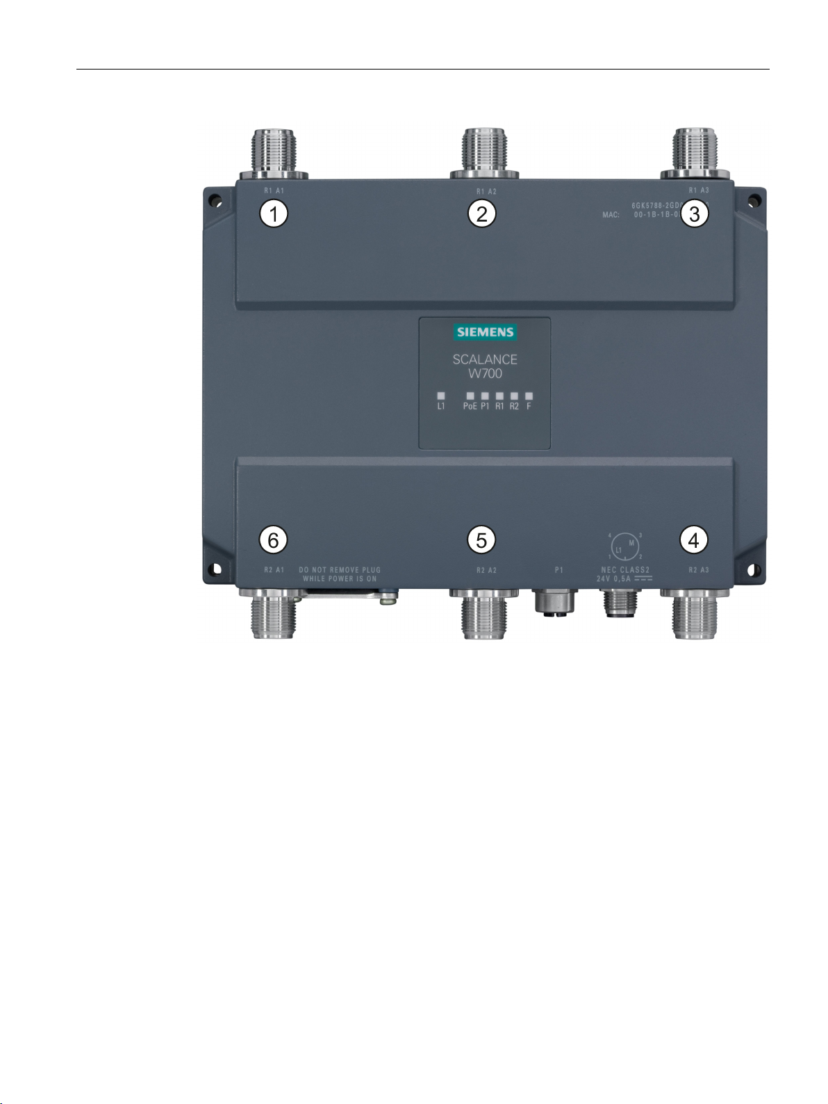
Managing access points
No.
Antenna connector
Designation WBM
①
R1 A1
Radio 1 antenna 1 - left
②
R1 A2
Radio 1 antenna 2 - middle
③
R1 A3
Radio 1 antenna 3 - right
④
R2 A3
Radio 2 antenna 3 - right
⑤
R2 A2
Radio 2 antenna 2 - middle
⑥
R2 A1
Radio 2 antenna 1 - left
5.3 Configuring access points
Figure 5-9 Antenna connectors
With the IEEE standard 802.11n, MIMO APs can transfer and evaluate different signals
(spatial streams) on the same channel. If several antennas are used, it is possible to
distinguish the different signals spatially.
From the drop-down list, select the antenna combination you want to configure for wireless
network Radio 1.
SCALANCE WLC711
Getting Started, 04/2016, C79000-G8976-C269-07
53
Page 54
Managing access points
Radio 2
5.3 Configuring access points
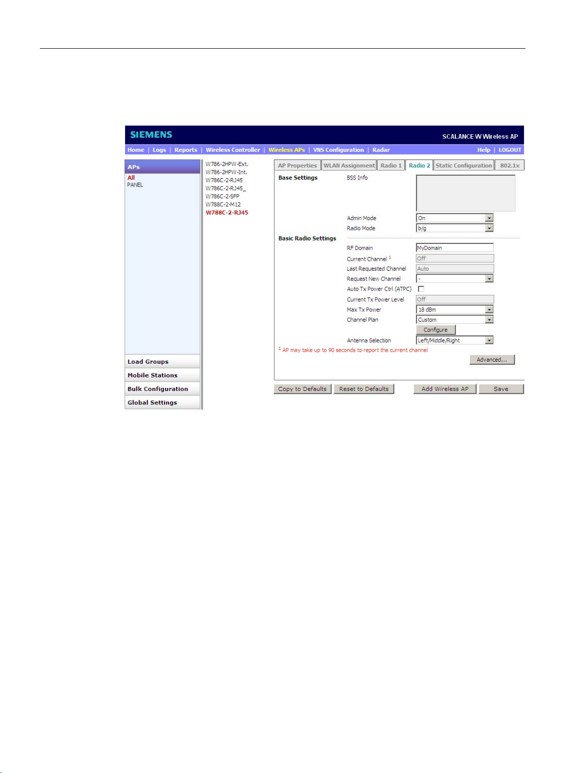
On the "APs > All" configuration page, select the "Radio 2" tab. The following window opens:
Figure 5-10 Wireless APs > APs > All > Radio 2 settings
The meaning of the settings is the same as on the "Radio 1" tab.
SCALANCE WLC711
54 Getting Started, 04/2016, C79000-G8976-C269-07
Page 55
Managing access points
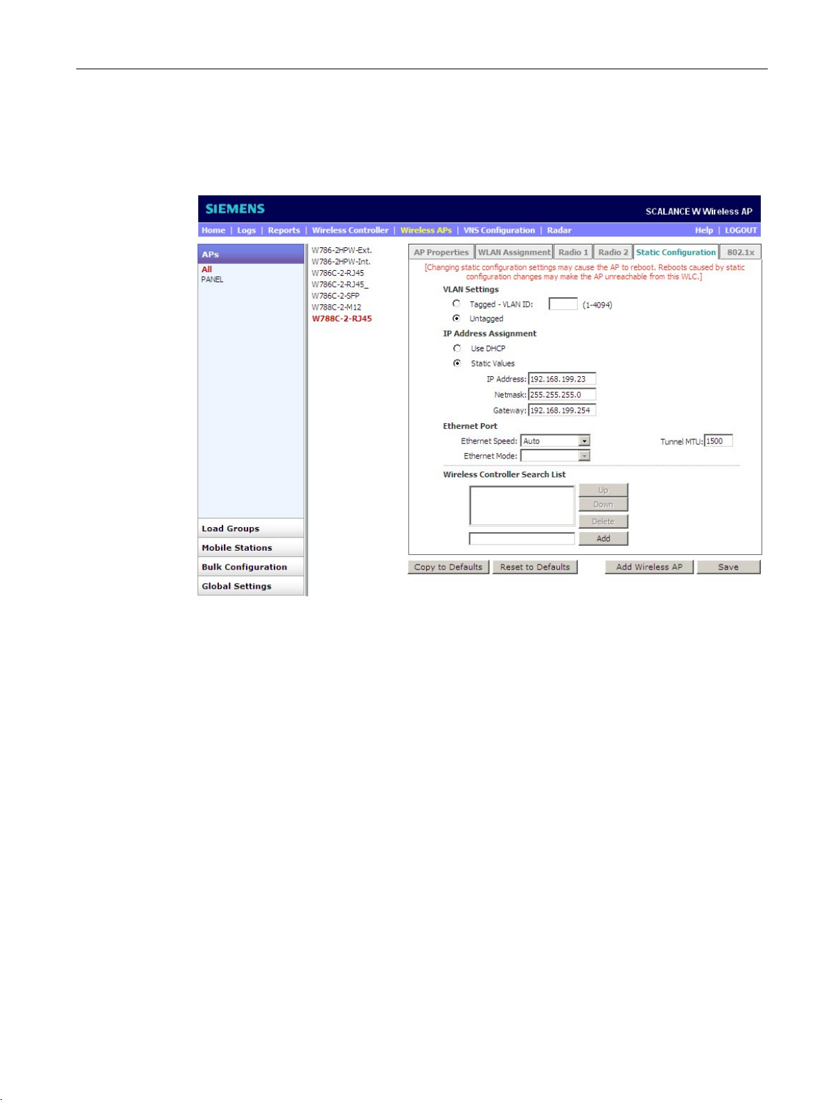
Static Configuration
VLAN Settings
"Tagged - VLAN ID" radio button
"Untagged" radio button
5.3 Configuring access points
On the "APs > All" configuration page, select the "Static Configuration" tab. The following
window opens:
Figure 5-11 Wireless APs > APs > All > Static Configuration
From the middle list, select the access point you want to configure. In the "Static
Configuration" tab, you make the settings to decide how the AP with the WLC and a switch
will connect.
Where necessary, adapt the settings to your requirements.
To send tagged packets, enable the radio button and enter the VLAN ID in the input box
beside it.
To send untagged packets, enable the radio button.
SCALANCE WLC711
Getting Started, 04/2016, C79000-G8976-C269-07
55
Page 56

Managing access points
IP Address Assignment
"Use DHCP" drop-down list
"Static Values" radio button
IP Address
Netmask
Gateway
Ethernet Port
"Ethernet Speed" drop-down list
"Tunnel MTU" input box
"Ethernet Mode" drop-down list
Full duplex
Half duplex
5.3 Configuring access points
To use DHCP, select the radio button. As a result, the selected AP obtains a dynamic IP
address from the DHCP server.
If you enable this radio button, the AP is assigned a static IP address. You can complete the
following input boxes:
●
Enter the IP address of the AP here.
●
Enter the netmask of the AP here.
●
Enter the gateway of the AP here.
In this area, select the speed and the mode of the Ethernet port.
Select a suitable speed for Ethernet. Make sure that the AP has exactly the same settings as
the switch. If you select "Auto", the speed is automatically negotiated with the switch. If you
select 100 or 10 Mbps, you can edit the Ethernet mode.
By entering an MTU size, you specify the threshold value at which packets are fragmented.
We recommend a maximum value of 1500.
Here, select the Ethernet mode:
●
Select this function so that data packets are sent and received simultaneously.
●
Select this function Select this function so that data packets are either sent or received.
SCALANCE WLC711
56 Getting Started, 04/2016, C79000-G8976-C269-07
Page 57

Managing access points
Wireless Controller Search List
Buttons
Up
Down
Delete
Add
802.1x
5.3 Configuring access points
If several WLCs are registered, they can be entered in the "Wireless Controller Search List"
ranking list. Normally, the AP logs on at the WLC at which it was last logged on. If the AP
cannot reach this WLC, it connects to the first WLC listed in the ranking list. If this list is
empty, the AP searches for a WLC using the Dynamic Host Configuration Protocol (DHCP)
or a Service Location Protocol Directory Agent (SLP DA) that is dependent on the
registration. The first time it registers, the AP first uses the information provided by DHCP. If
this does not exist, it starts an SLP multicast. If the AP is unsuccessful, the list must be
entered manually via an SSH connection.
With the following buttons, you can change the arrangement of the WLCs:
●
To move the controller up, select a controller from the list and click the "Up" button.
●
To move the controller down, select a controller from the list and click the "Down" button.
●
To remove a WLC from the list, click the "Delete" button.
●
To include a WLC in the list, enter the IP address of the WLC in the input box and click
the "Add" button.
The IEEE 802.1x standard is an authentication method that is used when the IE switch to
which the AP is connected uses port authentication, for example via a RADIUS server. You
will find more detailed information on configuration in the SCALANCE WLC711 User Guide.
SCALANCE WLC711
Getting Started, 04/2016, C79000-G8976-C269-07
57
Page 58
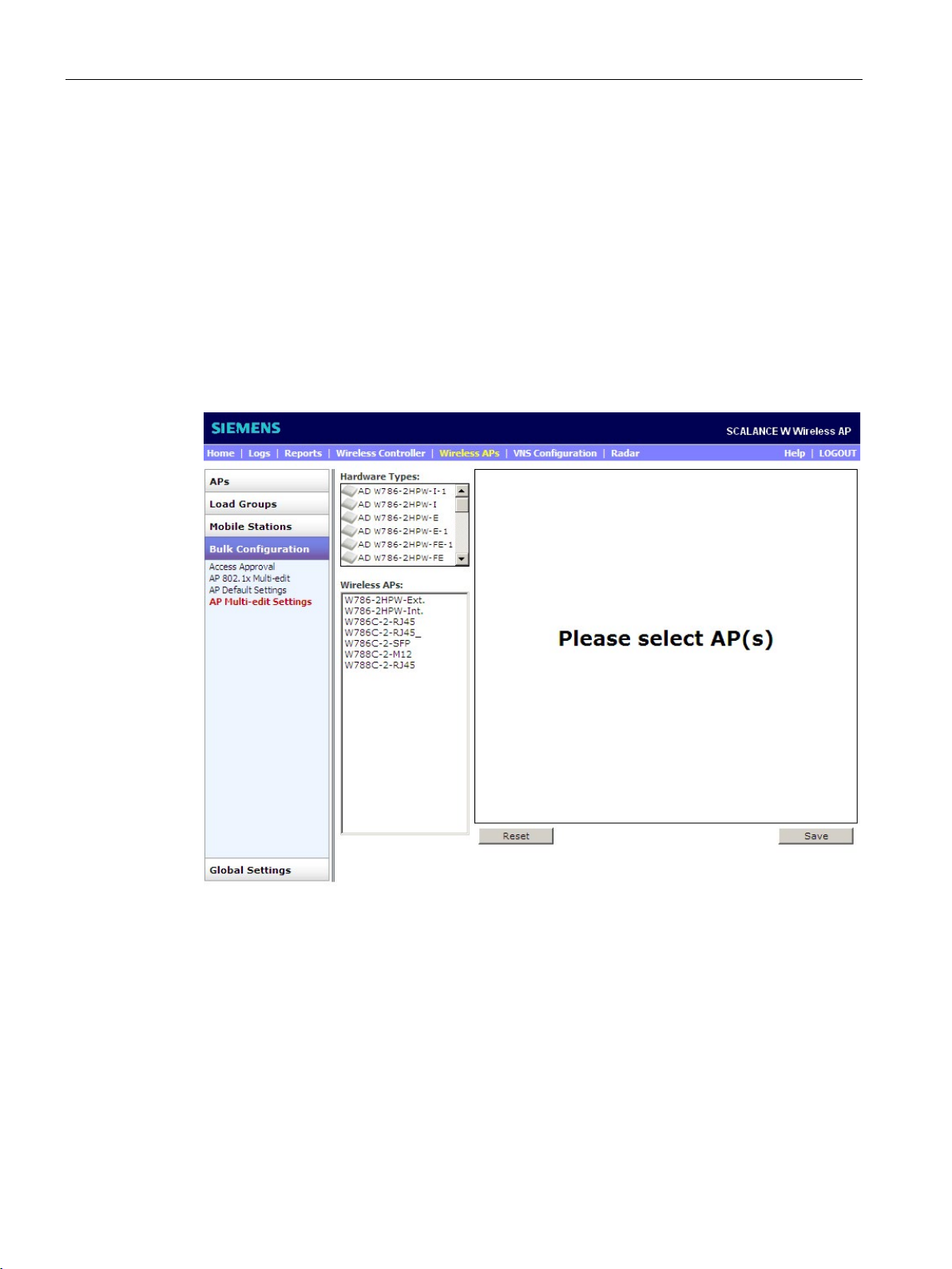
Managing access points
5.3.2
Multiple configuration
"Multi-edit" configuration page
AP Multi-Edit
"Hardware Types" list
5.3 Configuring access points
This section explains how to apply a setting to multiple access points. This gives you the
opportunity of configuring and managing several APs efficiently. To open the "Multi-edit"
configuration page, select the "Wireless AP > AP Multi-edit" menu command.
To open the "AP Multi-edit" configuration page, select the "Wireless APs > Bulk
Configuration > AP Multi-edit Settings" menu command. The following window opens:
Figure 5-12 AP Multi-edit
The "Hardware Types" list shows the hardware types of the APs that the SCALANCE
WLC711 supports.
If you select a hardware type from the list, all the APs that correspond to this hardware type
are shown in the "Wireless APs" list. If you select several hardware types with the Ctrl key,
the common sub properties of the hardware of the APs are displayed.
SCALANCE WLC711
58 Getting Started, 04/2016, C79000-G8976-C269-07
Page 59

Managing access points
Configuring access points at the same time
5.3 Configuring access points
To configure common sub properties of APs at the same time, follow the steps below:
1. To configure similar APs, select one or more hardware types from the middle list
"Hardware Types".
APs with the same configuration are displayed in the "Wireless APs" list.
2. In the "Wireless APs" list, select the APs you want to configure similarly.
In the right-hand area, you will see common configuration properties of the selected APs.
3. Configure the APs. You will find information on the significance of the individual
configuration options in the section "Single configuration (Page 45)".
SCALANCE WLC711
Getting Started, 04/2016, C79000-G8976-C269-07
59
Page 60

Managing access points
5.3 Configuring access points
SCALANCE WLC711
60 Getting Started, 04/2016, C79000-G8976-C269-07
Page 61
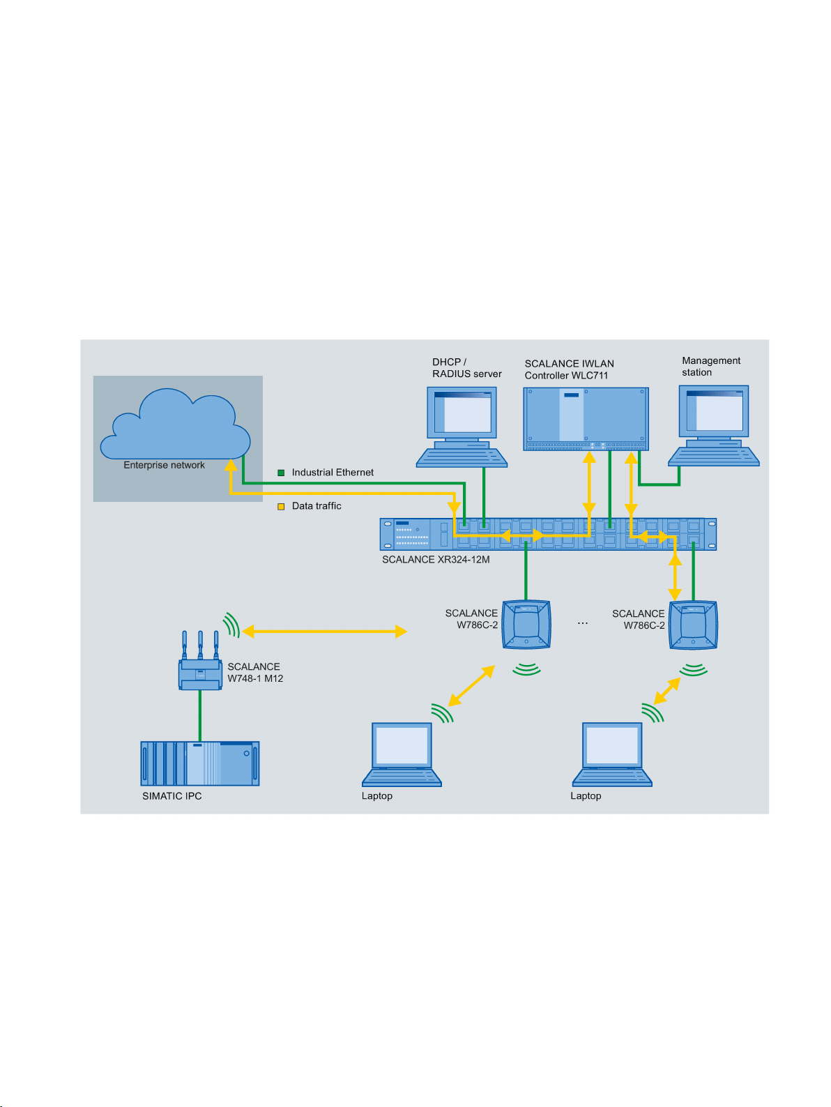
6
6.1
Use case: Bridged at WLC
Introduction
Description
The following graphic shows you the "Bridged at WLC" use case in a simplified form:
Figure 6-1 Use case - Bridged at WLC
The "Bridged at WLC" use case describes the following situation:
1. The WLC is connected to port "LAN 1" of the switch and is involved in the flow of data.
2. The WLC is connected to the "admin" port of the management station.
3. The APs are connected to the switch.
SCALANCE WLC711
Getting Started, 04/2016, C79000-G8976-C269-07
61
Page 62
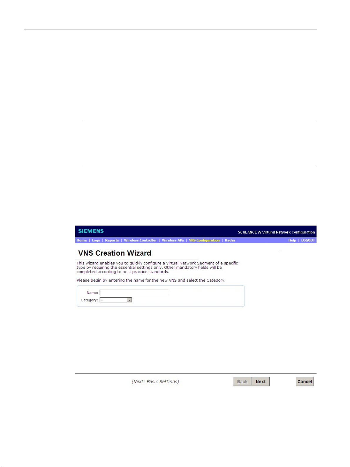
Configuring specific use cases with the wizard
Properties
Note
MAC mode
If you operate SCALANCE IWLAN clients SCALANCE W74x
mode "Manual" is supported.
In this mode only one Ethernet node may be connected to the client.
Procedure
6.1 Use case: Bridged at WLC
4. A server is connected to the switch.
5. The APs can be configured using the WLC.
This gives you the following options:
● There are no additional configurations, for example via WLAN settings on the switch.
● Fast roaming is more reliable since the switches are not involved.
-1, note that only the MAC
To configure the WLC, open the "VNS Creation Wizard" with the "VNS Configuration >
New... > Start VNS Wizard" menu command.
The following window opens:
Figure 6-2 Use case - Bridged at WLC - "VNS Creation Wizard" wizard
SCALANCE WLC711
62 Getting Started, 04/2016, C79000-G8976-C269-07
Page 63
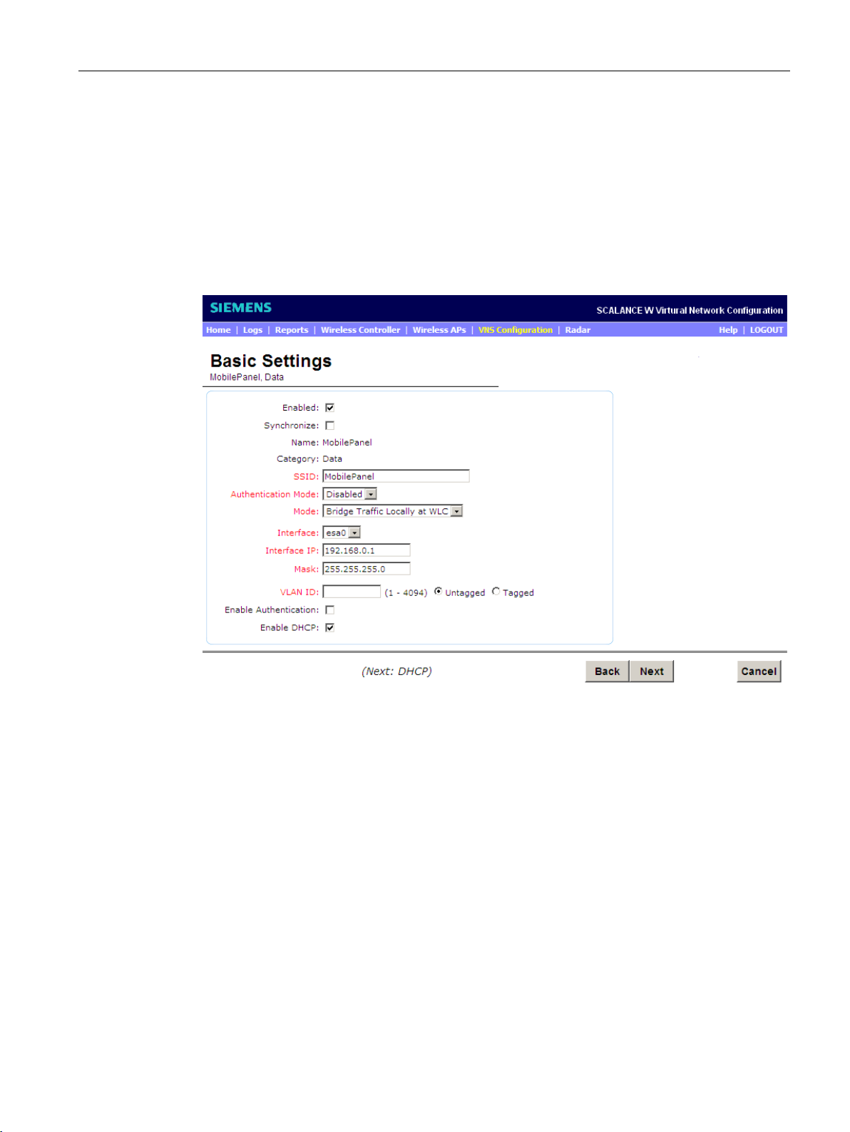
Configuring specific use cases with the wizard
6.1 Use case: Bridged at WLC
Follow these steps during configuration:
1. In the "Name" input box, enter a name for the VNS configuration, for example "WLC
Data".
2. Select the value "Data" from the "Category" drop-down list. This influences topologies,
policies and service settings.
3. To move to the next page of the wizard, click the "Next" button.
The following window opens:
Figure 6-3 Use case - Bridged at WLC - "Basic Settings" wizard
Follow these steps during configuration:
1. Select the "Enabled" check box. This means that on completion of the wizard, the WLAN
settings are activated immediately.
2. To identify the network, enter a name for the SSID, for example "WLC Data" in the "SSID"
input box.
3. If you do not require 802.1x authentication, select the value "Disabled" from the
"Authentication Mode" drop-down list.
4. From the "Mode" drop-down list, select the value "Bridge Traffic Locally at WLC".
5. Select the value "esa0" from the "Interface" drop-down list.
6. Enter the IP address of the interface of the WLC in the "Interface IP" input box.
7. Enter the netmask of the data port of the WLC in the "Mask" input box.
8. Enter the VLAN ID in the "VLAN ID" input box.
SCALANCE WLC711
Getting Started, 04/2016, C79000-G8976-C269-07
63
Page 64
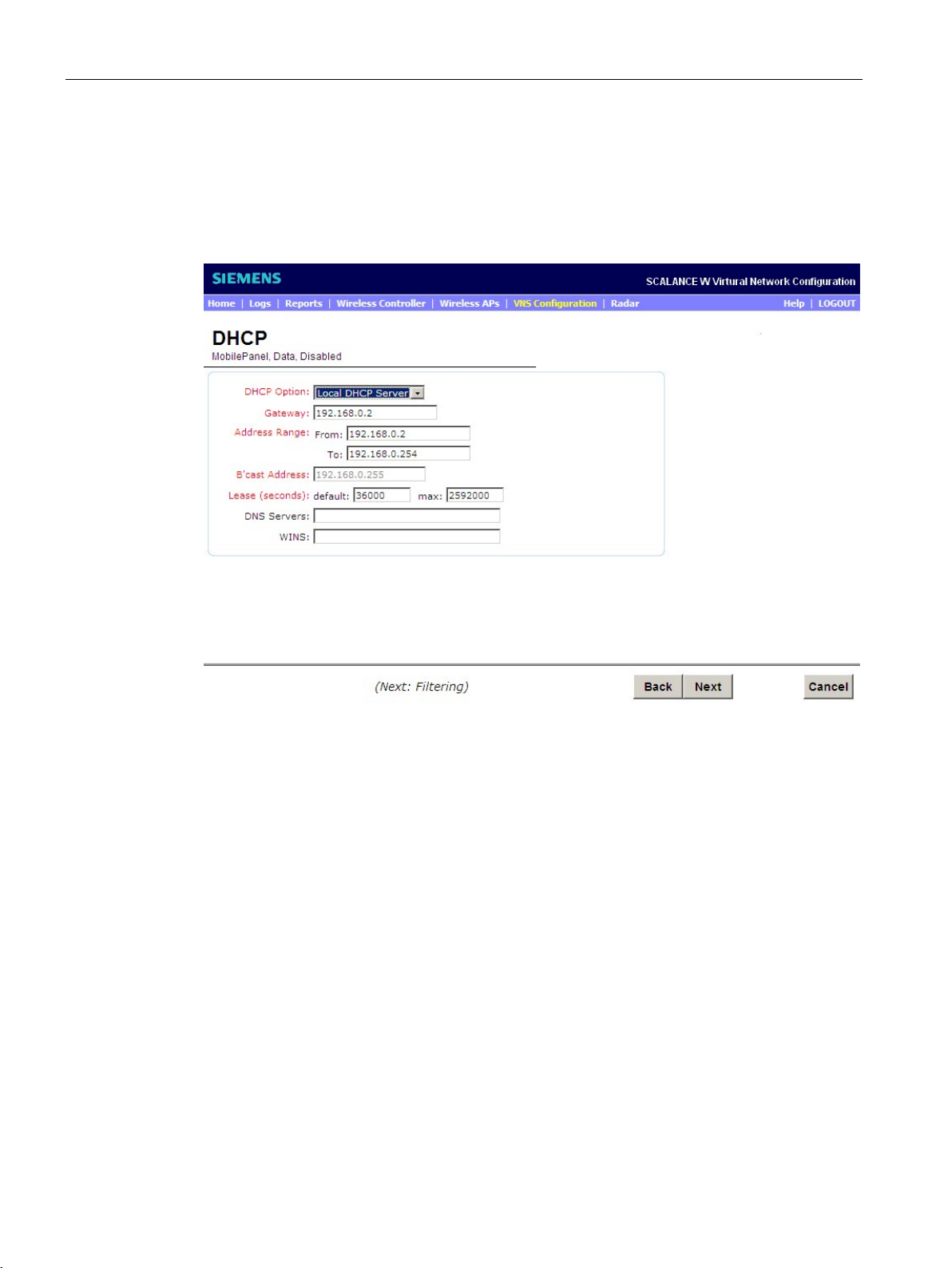
Configuring specific use cases with the wizard
6.1 Use case: Bridged at WLC
9. To be able to send packets untagged, enable the "Untagged" radio button.
10.To use the DHCP protocol for the access points, select the "Enable DHCP" check box.
11.To move to the next page of the wizard, click the "Next" button.
The following window opens:
Figure 6-4 Use case - Bridged at WLC - "DHCP" wizard
Follow these steps during configuration:
1. To operate the DHCP server as a local server, select the value "Local DHCP Server"
from the "DHCP Option" drop-down list.
2. Enter the default router of the network in the "Gateway" input box.
3. Enter the address range to be provided by the WLC in the input boxes of the "Address
Range".
4. Enter a default and maximum value for the lease time in the input boxes of "Lease
(seconds)".
5. To move to the next page of the wizard, click the "Next" button.
SCALANCE WLC711
64 Getting Started, 04/2016, C79000-G8976-C269-07
Page 65
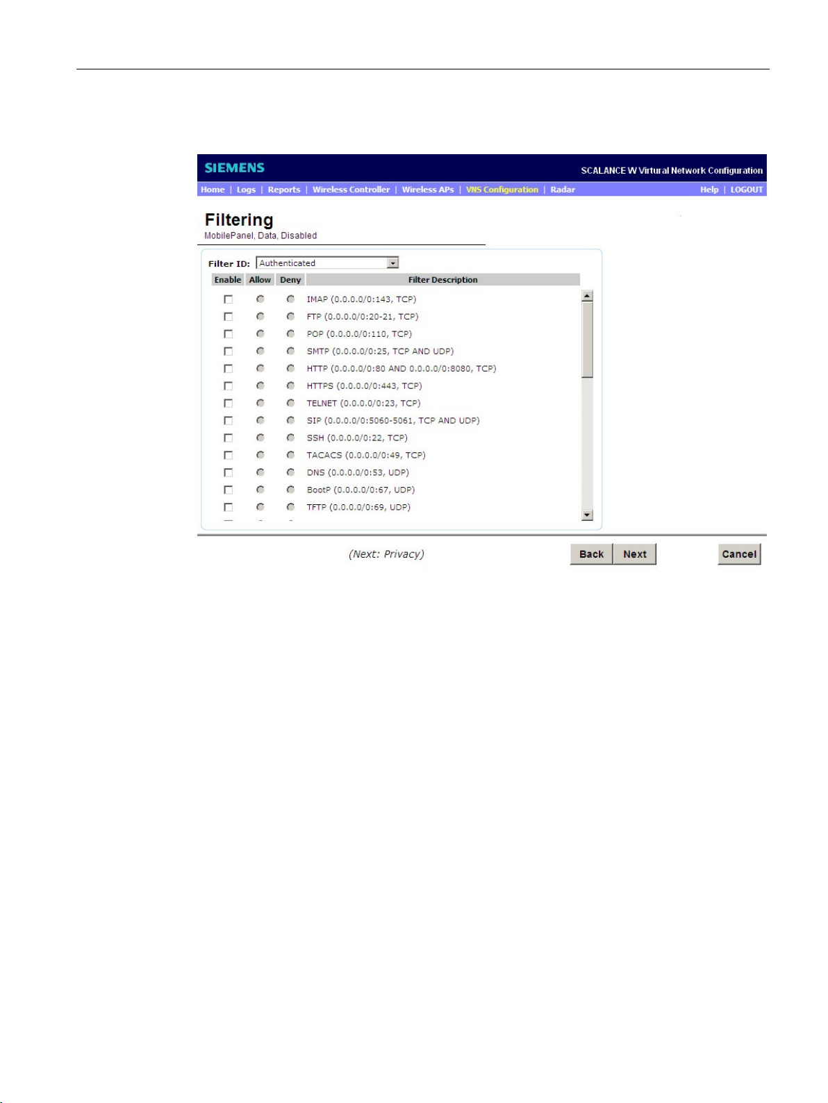
Configuring specific use cases with the wizard
6.1 Use case: Bridged at WLC
The following window opens:
Figure 6-5 Use case - Bridged at WLC - "Filtering" wizard
Follow these steps during configuration:
1. Select the value "Authenticated" from the "Filter ID" drop-down list.
2. To permit all data traffic, enable the "All Other Traffic" radio button at the end of the list.
3. To move to the next page of the wizard, click the "Next" button.
The following window opens:
SCALANCE WLC711
Getting Started, 04/2016, C79000-G8976-C269-07
65
Page 66
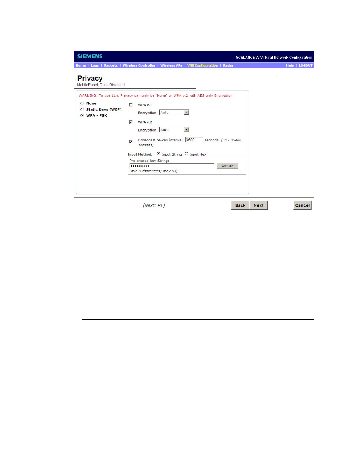
Configuring specific use cases with the wizard
Note
Access points with the IEEE 802.11n standard do not support the "Auto" function in WPA
v.2.
6.1 Use case: Bridged at WLC
Figure 6-6 Use case - Bridged at WLC - "Privacy" wizard
On this configuration page, you configure WPA2-PSK. Follow these steps during
configuration:
1. Enable the "WPA - PSK" radio button.
2. Select the "WPA v.2" check box to activate the encryption methods.
3. Select the entry "Auto" from the "Encryption" drop-down list. This makes the two security
protocols AES and CCMP available.
4. So that clients have to log on again after a certain time, select the "Broadcast re-key
interval" check box and enter the value "3600" in the input box.
5. To be able to enter a character string, enable the "Input String" radio button beside "Input
Method".
6. Enter the future password of the WLAN as a character string, for example
"WLCDATA123".
7. To move to the next page of the wizard, click the "Next" button.
SCALANCE WLC711
66 Getting Started, 04/2016, C79000-G8976-C269-07
Page 67
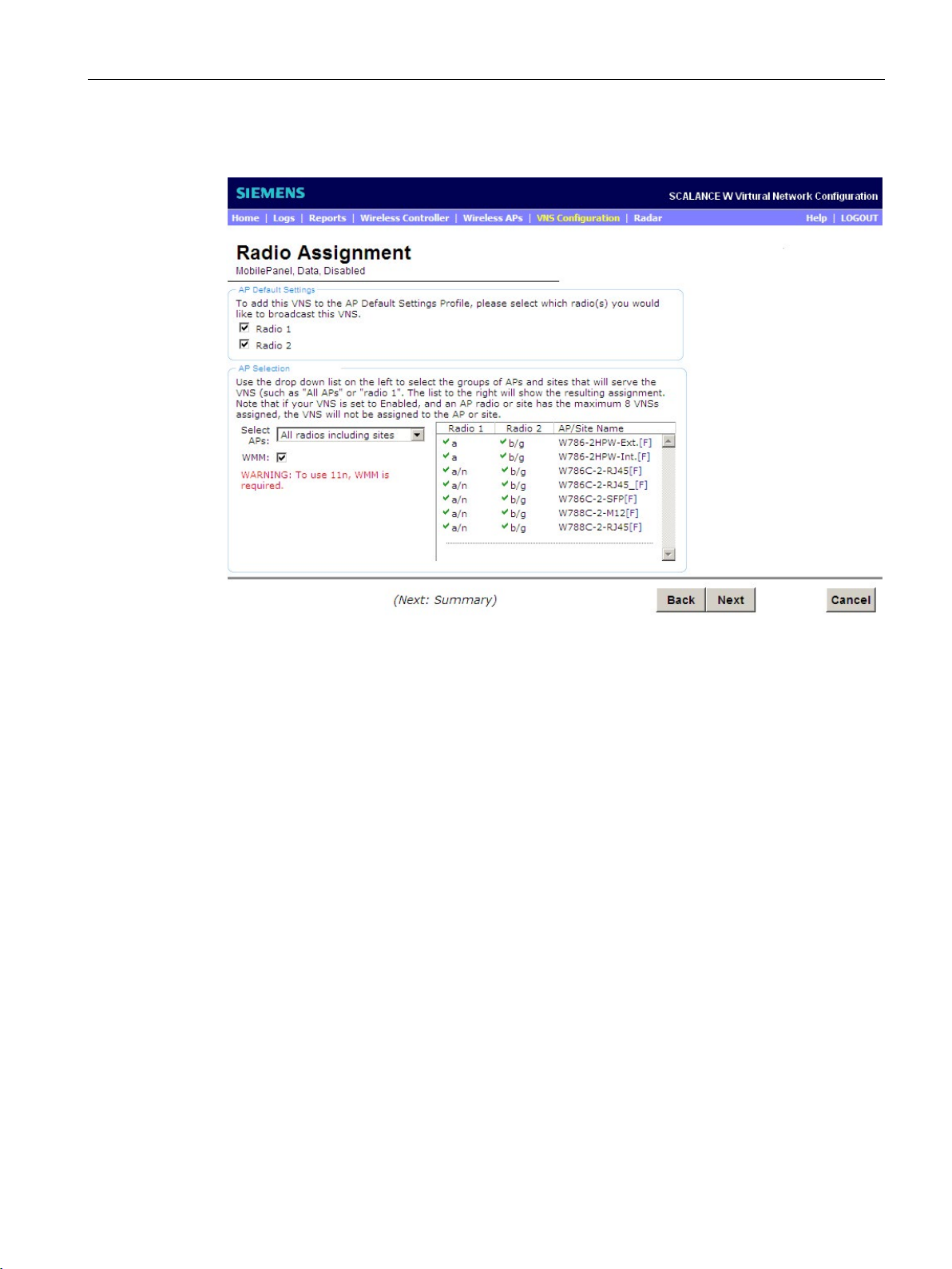
Configuring specific use cases with the wizard
6.1 Use case: Bridged at WLC
The following window opens:
Figure 6-7 Use case - Bridged at WLC - "Radio Assignment" wizard
Follow these steps during configuration:
1. To assign the WLAN as default, select the "Radio 1" and "Radio 2" check boxes.
2. From the "Select APs" drop-down list, select the "all radios" entry so that all APs are
activated.
3. To allow the IEEE standard 802.11n to be used, select the "WMM" (WiFi Multimedia)
check box.
4. To move to the next page of the wizard, click the "Next" button.
SCALANCE WLC711
Getting Started, 04/2016, C79000-G8976-C269-07
67
Page 68
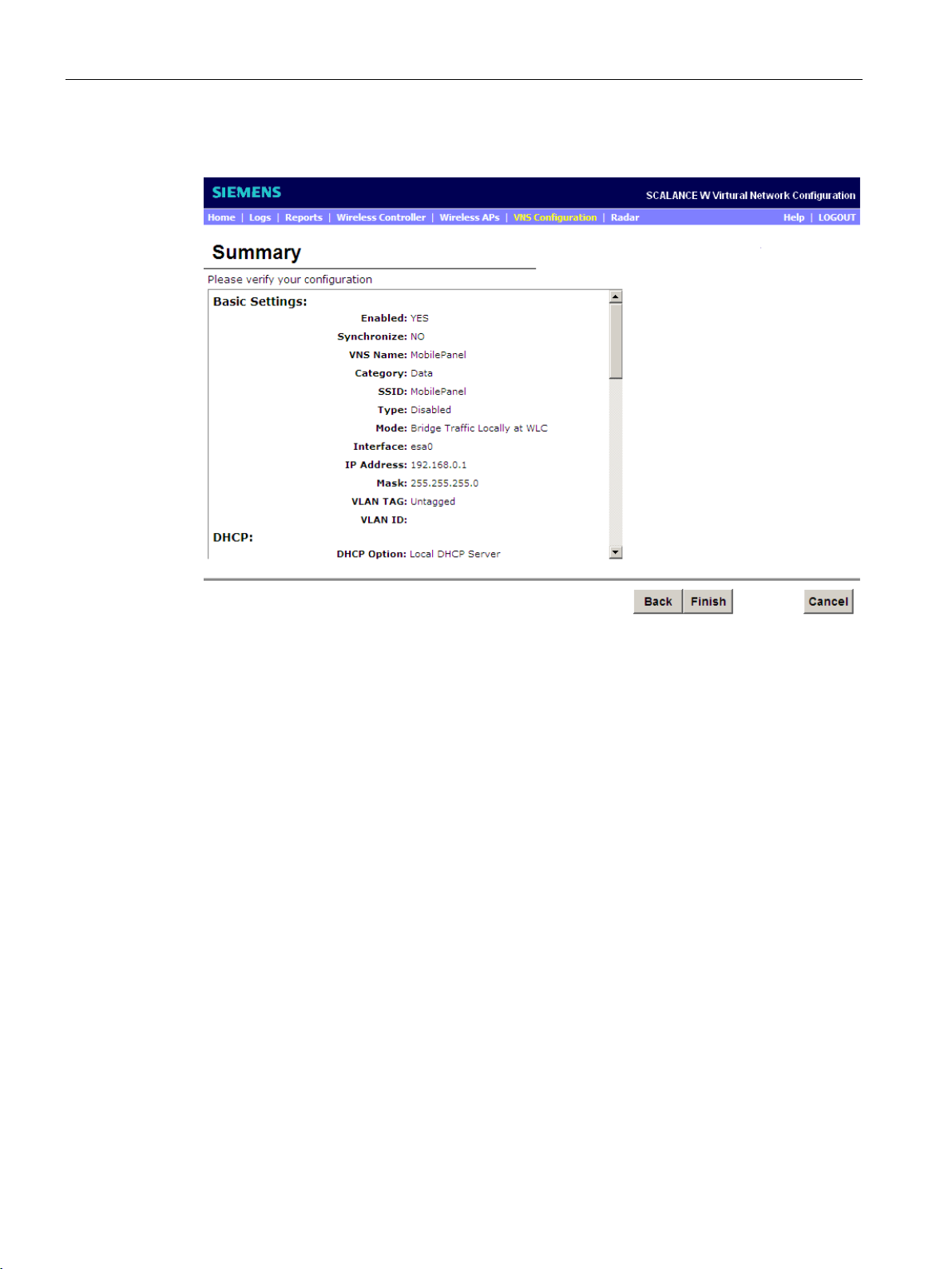
Configuring specific use cases with the wizard
6.1 Use case: Bridged at WLC
The following window opens:
Figure 6-8 Use case - Bridged at WLC - "Summary" wizard
On this page, you can see and check all the settings. If incorrect information has been
entered, you can change the entry by returning to the required configuration page with the
"Back" button. All other settings are retained and do not need to be reconfigured.
If the entries are correct, click the "Finish" button to move to the next page. If you want to
stop the action, click the "Cancel" button.
To move to the next page of the wizard, click the "Finish" button.
SCALANCE WLC711
68 Getting Started, 04/2016, C79000-G8976-C269-07
Page 69
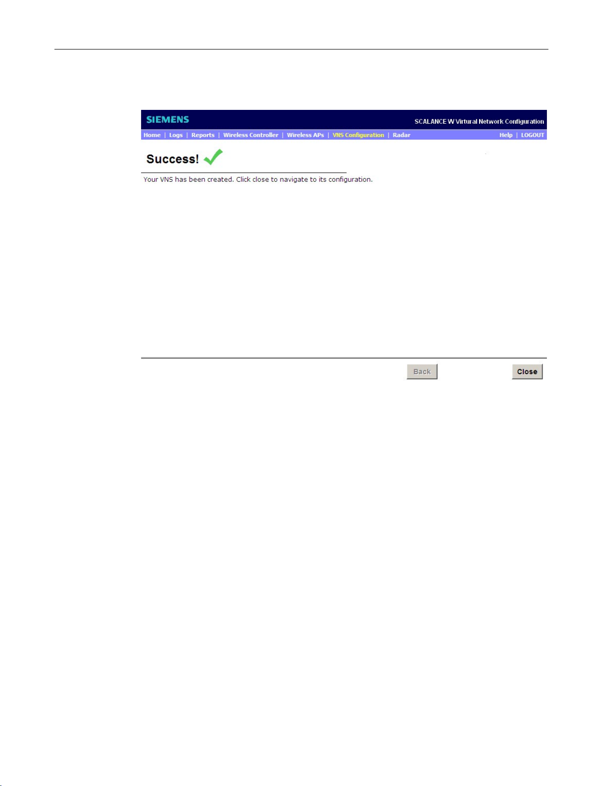
Configuring specific use cases with the wizard
6.1 Use case: Bridged at WLC
The following window opens:
Figure 6-9 Application - Bridged at WLC Wizard "Success" (wizard completed successfully)
Your settings are confirmed on this page. To exit the wizard, click the "Close" button. You
have now completed the wizard successfully.
SCALANCE WLC711
Getting Started, 04/2016, C79000-G8976-C269-07
69
Page 70
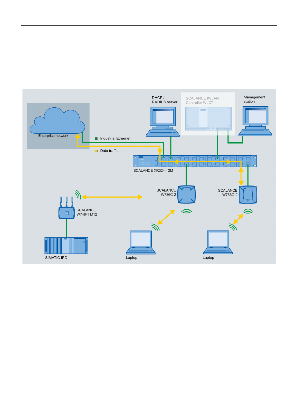
Configuring specific use cases with the wizard
6.2
Use case: Bridged at AP
Appearance
Description
not
6.2 Use case: Bridged at AP
The following graphic shows you the "Bridged at AP" use case in a simplified form:
Figure 6-10 Use case - Bridged at AP
The "Bridged at AP" use case describes the following situation:
1. The WLC is connected to port "LAN 1" of the switch and is
data.
2. The WLC is connected to the "admin" port of the management station.
3. The APs are connected to the switch.
4. A DHCP server is connected to the switch.
5. The APs can be configured using the WLC.
SCALANCE WLC711
70 Getting Started, 04/2016, C79000-G8976-C269-07
involved in the flow of
Page 71

Configuring specific use cases with the wizard
Properties
Note
PROFINET IO communication
For complex plants requiring PROFINET IO communication, stand
iPCF support are recommended.
Note
MAC mode
If you
modes "Manual", "Own" and "Automatic" are supported. If several Ethernet notes need to be
operated downstream from the IWLAN client, use the MAC mode "Own".
Procedure
6.2 Use case: Bridged at AP
This gives you the following options:
● The APs also remain active even if the WLC fails.
● This WLAN service can be suitable for PROFINET IO if WLAN clients move within the
range of one AP (no roaming of WLAN clients between several APs).
● Avoidance of a possible bottleneck with the bandwidth. This can result when all WLAN
clients need to share the data port "esa0" on the WLC.
-alone access points with
operate SCALANCE IWLAN clients SCALANCE W74x-1, note that only the MAC
To configure the WLC, open the "VNS Creation Wizard" with the "VNS Configuration >
New... > Start VNS Wizard" menu command.
The following window opens:
SCALANCE WLC711
Getting Started, 04/2016, C79000-G8976-C269-07
71
Page 72
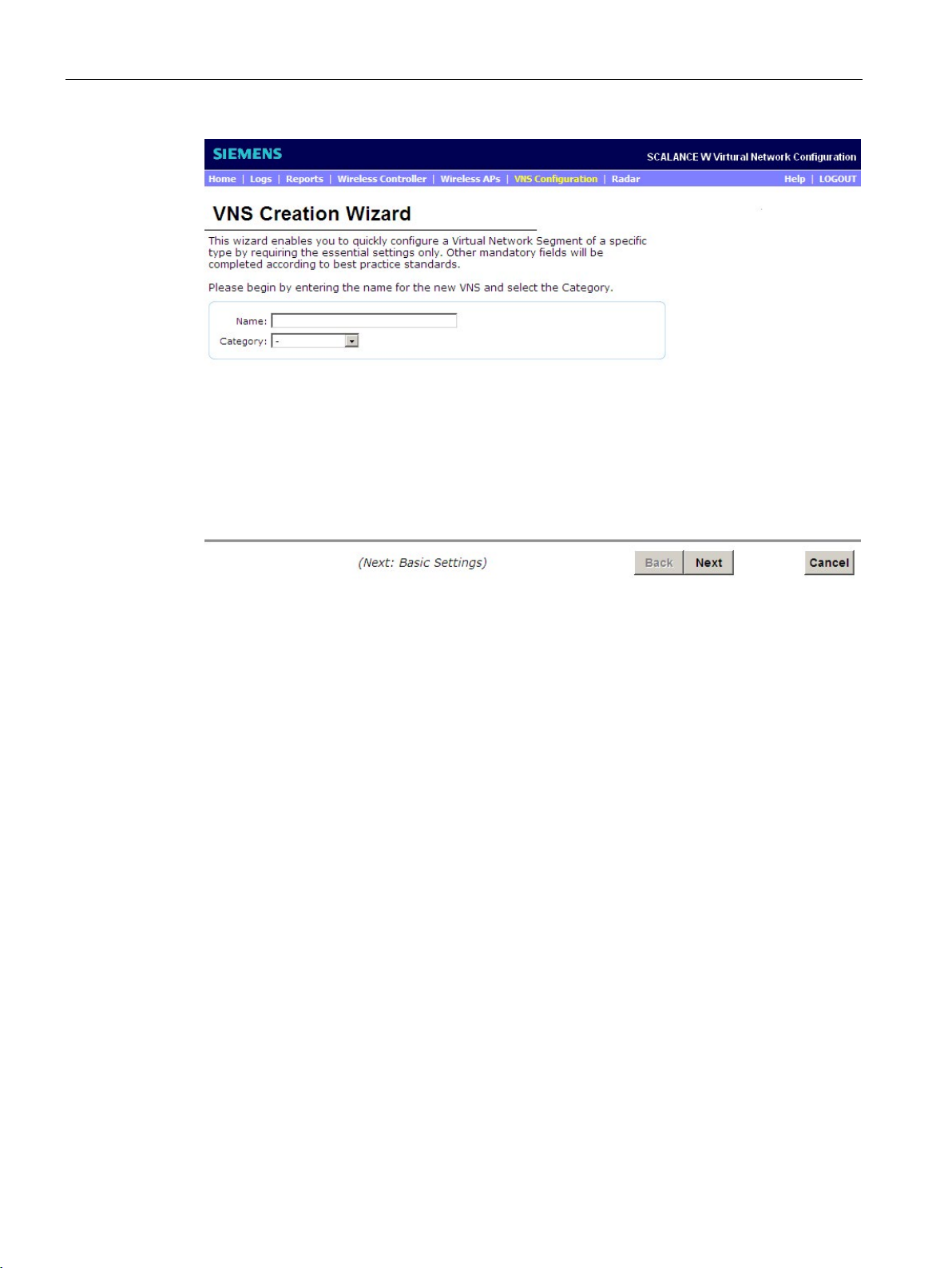
Configuring specific use cases with the wizard
6.2 Use case: Bridged at AP
Figure 6-11 Use case - Bridged at WLC - "VNS Creation Wizard" wizard
Follow these steps during configuration:
1. In the "Name" input box, enter a name for the VNS configuration, for example "WLC
Data".
2. Select the value "Data" from the "Category" drop-down list. This influences topologies,
policies and service settings.
3. To move to the next page of the wizard, click the "Next" button.
SCALANCE WLC711
72 Getting Started, 04/2016, C79000-G8976-C269-07
Page 73
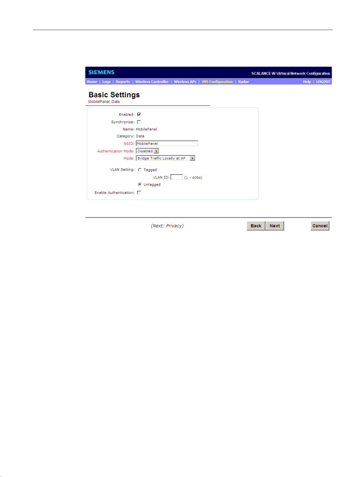
Configuring specific use cases with the wizard
6.2 Use case: Bridged at AP
The following window opens:
Figure 6-12 Use case - Bridged at AP - "Basic Settings" wizard
Follow these steps during configuration:
1. Select the "Enabled" check box. This means that on completion of the wizard, the WLAN
settings are activated immediately.
2. To identify the network, enter a name for the SSID, for example "WLC Data" in the "SSID"
input box.
3. If you do not require 802.1x authentication, select the value "Disabled" from the
"Authentication Mode" drop-down list.
4. To have the data traffic only via the APs and not via the WLC, select the value "Bridge
Traffic Locally at AP" from the "Mode" drop-down list.
5. To be able to send packets untagged, enable the "Untagged" radio button.
6. To move to the next page of the wizard, click the "Next" button.
The following window opens:
SCALANCE WLC711
Getting Started, 04/2016, C79000-G8976-C269-07
73
Page 74
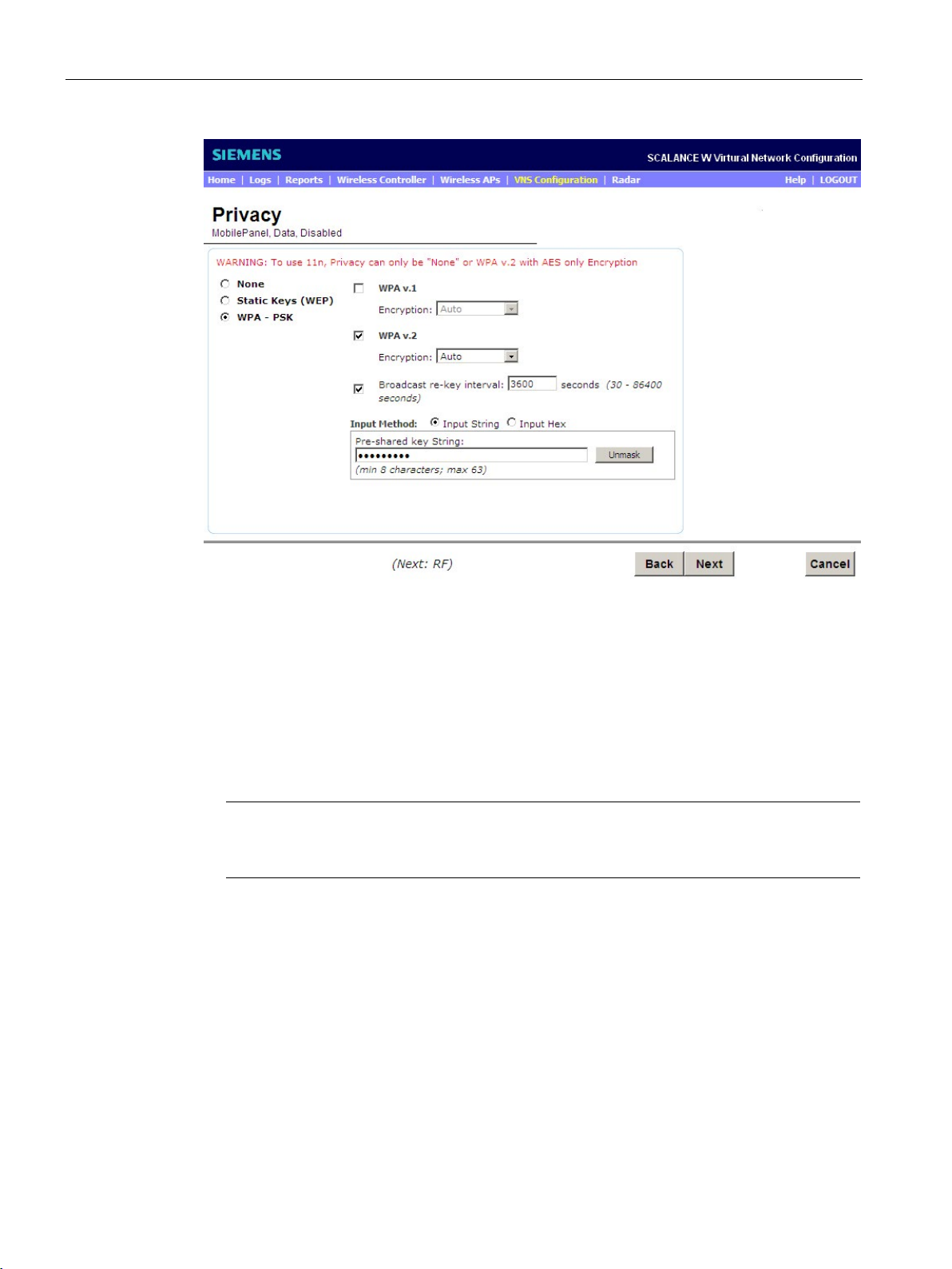
Configuring specific use cases with the wizard
Note
Access points with the IEEE 802.11n standard do not support the "Auto" function in WPA
v.2.
6.2 Use case: Bridged at AP
Figure 6-13 Use case - Bridged at WLC - "Privacy" wizard
On this configuration page, you configure WPA2-PSK. Follow these steps during
configuration:
1. Enable the "WPA - PSK" radio button.
2. Select the "WPA v.2" check box to activate the encryption methods.
3. Select the entry "Auto" from the "Encryption" drop-down list. This makes the two security
protocols AES and CCMP available.
4. So that clients have to log on again after a certain time, select the "Broadcast re-key
interval" check box and enter the value "3600" in the input box.
5. To be able to enter a character string, enable the "Input String" radio button beside "Input
Method".
6. Enter the future password of the WLAN as a character string, for example
"WLCDATA123".
7. To move to the next page of the wizard, click the "Next" button.
SCALANCE WLC711
74 Getting Started, 04/2016, C79000-G8976-C269-07
Page 75
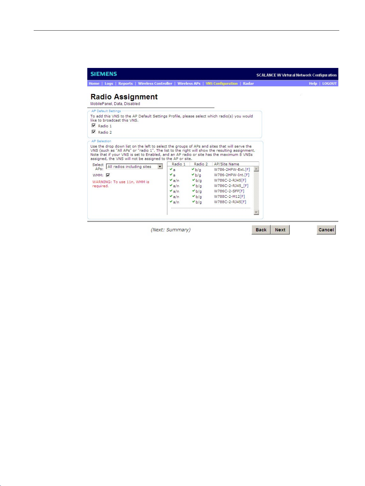
Configuring specific use cases with the wizard
6.2 Use case: Bridged at AP
The following window opens:
Figure 6-14 Use case - Bridged at WLC - "Radio Assignment" wizard
Follow these steps during configuration:
1. To assign the WLAN as default, select the "Radio 1" and "Radio 2" check boxes.
2. From the "Select APs" drop-down list, select the "all radios" entry so that all APs are
activated.
3. To allow the IEEE standard 802.11n to be used, select the "WMM" (WiFi Multimedia)
check box.
4. To move to the next page of the wizard, click the "Next" button.
SCALANCE WLC711
Getting Started, 04/2016, C79000-G8976-C269-07
75
Page 76
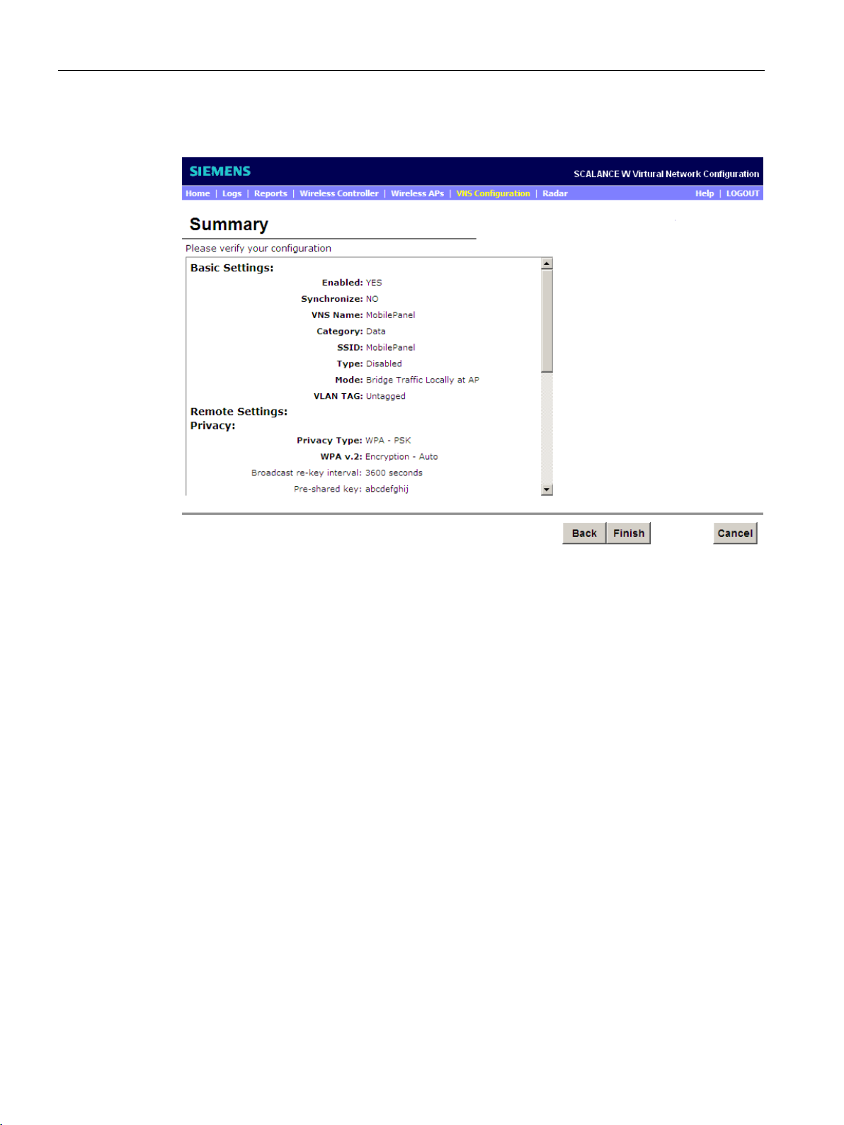
Configuring specific use cases with the wizard
6.2 Use case: Bridged at AP
The following window opens:
Figure 6-15 Use case - Bridged at AP" - "Summary" wizard
On this page, you can see and check all the settings. If incorrect information has been
entered, you can change the entry by returning to the required configuration page with the
"Back" button. All other settings are retained and do not need to be reconfigured.
If the entries are correct, click the "Finish" button to move to the next page. If you want to
stop the action, click the "Cancel" button.
To move to the next page of the wizard, click the "Next" button.
SCALANCE WLC711
76 Getting Started, 04/2016, C79000-G8976-C269-07
Page 77
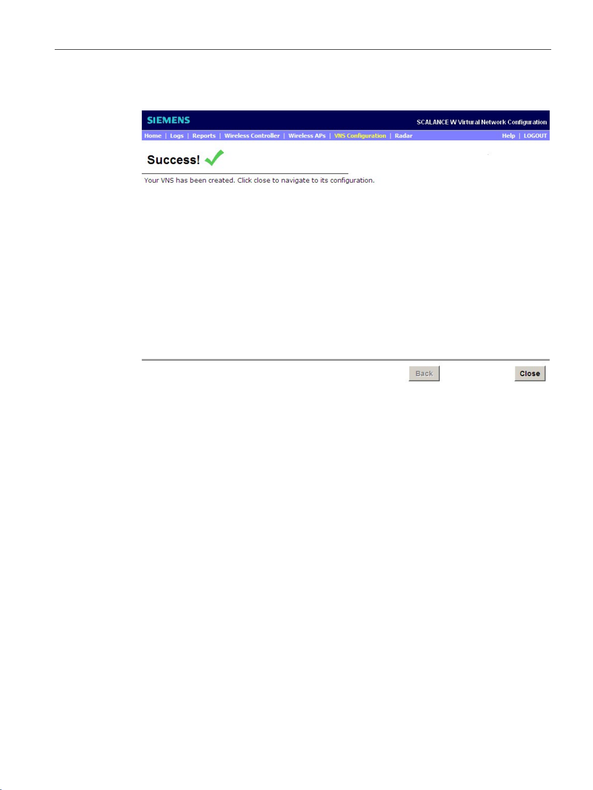
Configuring specific use cases with the wizard
6.2 Use case: Bridged at AP
The following window opens:
Figure 6-16 Application - Bridged at WLC Wizard "Success" (wizard completed successfully)
Your settings are confirmed on this page. To exit the wizard, click the "Close" button. You
have now completed the wizard successfully.
SCALANCE WLC711
Getting Started, 04/2016, C79000-G8976-C269-07
77
Page 78

Configuring specific use cases with the wizard
6.2 Use case: Bridged at AP
SCALANCE WLC711
78 Getting Started, 04/2016, C79000-G8976-C269-07
Page 79
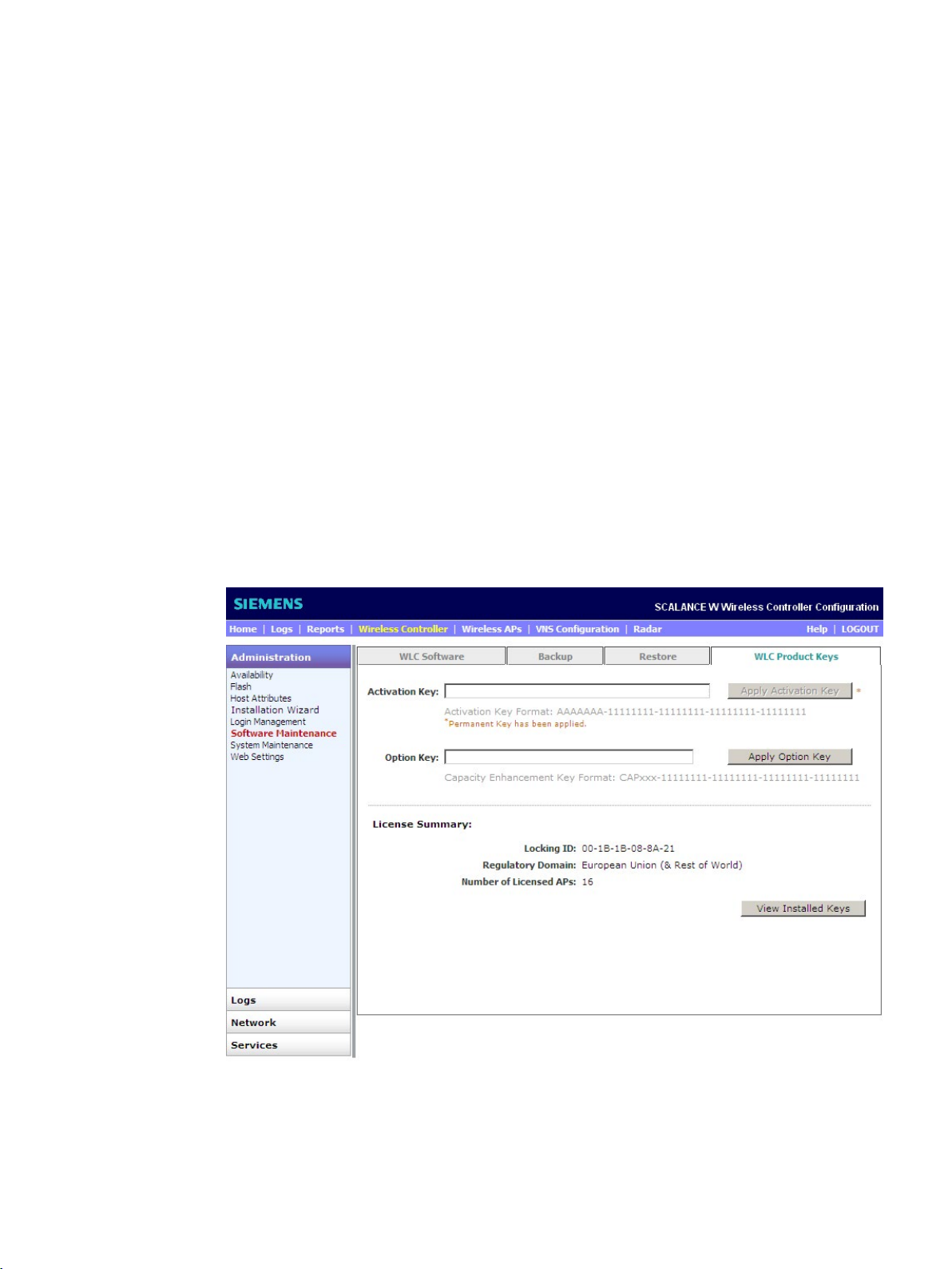
7
7.1
Expanding the number of manageable access points
Introduction
"WLC Product Keys" configuration page
When the SCALANCE WLC711 ships, up to 16 controller-based access points can be
operated. With the WLC-700 license, you can use a further 16 additional access points with
the SCALANCE WLC711. The order number of the license key WLC-700 is 6GK5 907
1SB00.
On this page, you can expand the number of access points. To open the "WLC Product
Keys" configuration page, select the menu command "Wireless Controller > Administration
> Software Maintenance" and select the "WLC Product Keys" tab. The following window
opens:
Figure 7-1 Software Maintenance - WLC Product Keys
SCALANCE WLC711
Getting Started, 04/2016, C79000-G8976-C269-07
79
Page 80

Optional configuration
Procedure
Note
Activation key
The activation key is also s
readers, the activation key can be entered directly in the "Activation Key" input box.
7.1 Expanding the number of manageable access points
Follow these steps during configuration:
1. Enter the activation key in the "Activation Key" input box. This activation key is entered in
the certificate.
tored in the certificate in a Data Matrix code. With code
2. To apply the activation key, click the "Apply Activation Key" button.
3. Check whether or not the activation key was adopted successfully by clicking the "View
Installed Keys" button. The following window opens:
SCALANCE WLC711
80 Getting Started, 04/2016, C79000-G8976-C269-07
Page 81
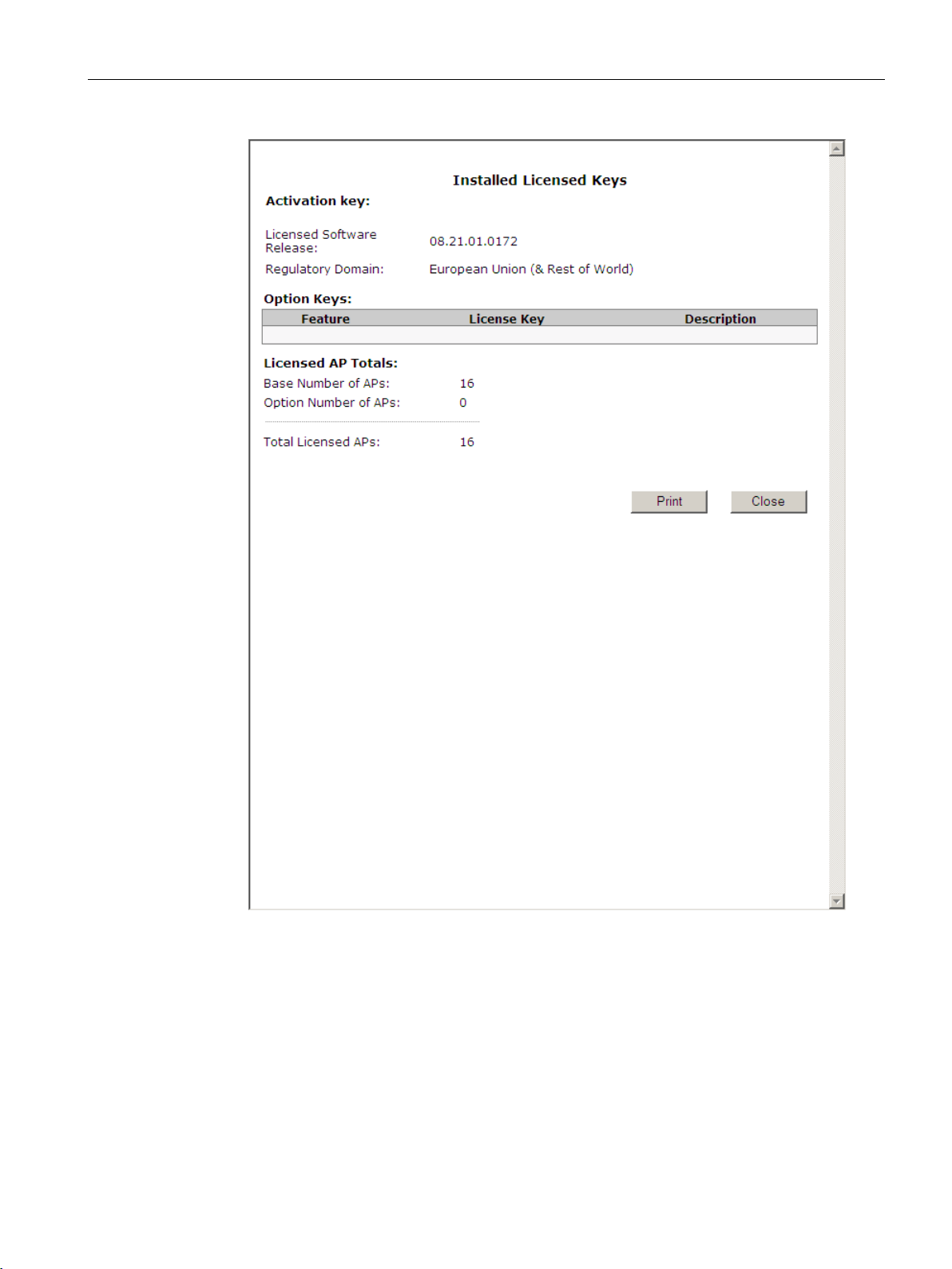
Optional configuration
Result
7.1 Expanding the number of manageable access points
Figure 7-2 Installed activation key
Following the capacity upgrade, you can operate up to 48 controller-based access points
with the SCALANCE WLC711.
SCALANCE WLC711
Getting Started, 04/2016, C79000-G8976-C269-07
81
Page 82

Optional configuration
7.2
Access using the Command Line Interface (CLI)
Introduction
Note
Hyper Terminal
The CLI can be used with Hyper Terminal via the serial interface (RS
with Secure Shell (SSH) via an Ethernet connection. How to use the se
explained in the SCALANCE WLC711 Maintenance Guide.
Note
You should only use the command line interface if you are an experienced user. Even
commands that bring about fundamental changes to the configuration are normally executed
with
Reading the IP address
Syntax
Parameters
Parameters
Meaning
L3
command and displaying all layer 3 configured topologies (Physical, Admin, B@AP or
Routed).
Meaning of the parameters
Example
7.2 Access using the Command Line Interface (CLI)
With the Command Line Interface (CLI), you can make all the configuration settings for the
device. The CLI provides the same options as Web Based Management (WBM). You should
therefore also read the detailed explanations of the parameters in the SCALANCE WLC711
CLI Reference Guide.
-232) of the WLC or
rial interface is
out a prompt for confirmation.
With CLI commands, you can read out IP addresses of a topology. This is helpful if, for
example, you require an overview of the IP address currently being used. Note that only
layer 3 configured topologies are read out (Physical, Admin, Bridged at Controller or
Routed).
Call up the CLI command with the following entry:
show topology [l3]
The meaning of the parameters is as follows:
You can identify an IP address by entering its interface name or by entering the L3
WLC.siemens.com# show topology l3
SCALANCE WLC711
82 Getting Started, 04/2016, C79000-G8976-C269-07
Page 83

Optional configuration
Result
Name
Mode
L3:IP
1:Admin
admin
192.168.2.180
2:physical
1 physical
192.168.199.1
Setting the IP address
Example
Parameters
Meaning
192.168.2.180
IP address
/24
Subnet mask
Meaning of the parameters
7.2 Access using the Command Line Interface (CLI)
With CLI commands, you can also set the IP addresses of a topology.
This is helpful if, for example, you want to change the IP address of the "Admin" topology or
want to assign an IP address to a new topology.
WLC.siemens.com# topology
WLC.siemens.com:topology# Admin
WLC.siemens.com:topology:Admin# l3
WLC.siemens.com:topology:Admin:l3# ip 192.168.2.180/24
WLC.siemens.com:topology:Admin:l3# apply
SCALANCE WLC711
Getting Started, 04/2016, C79000-G8976-C269-07
83
Page 84
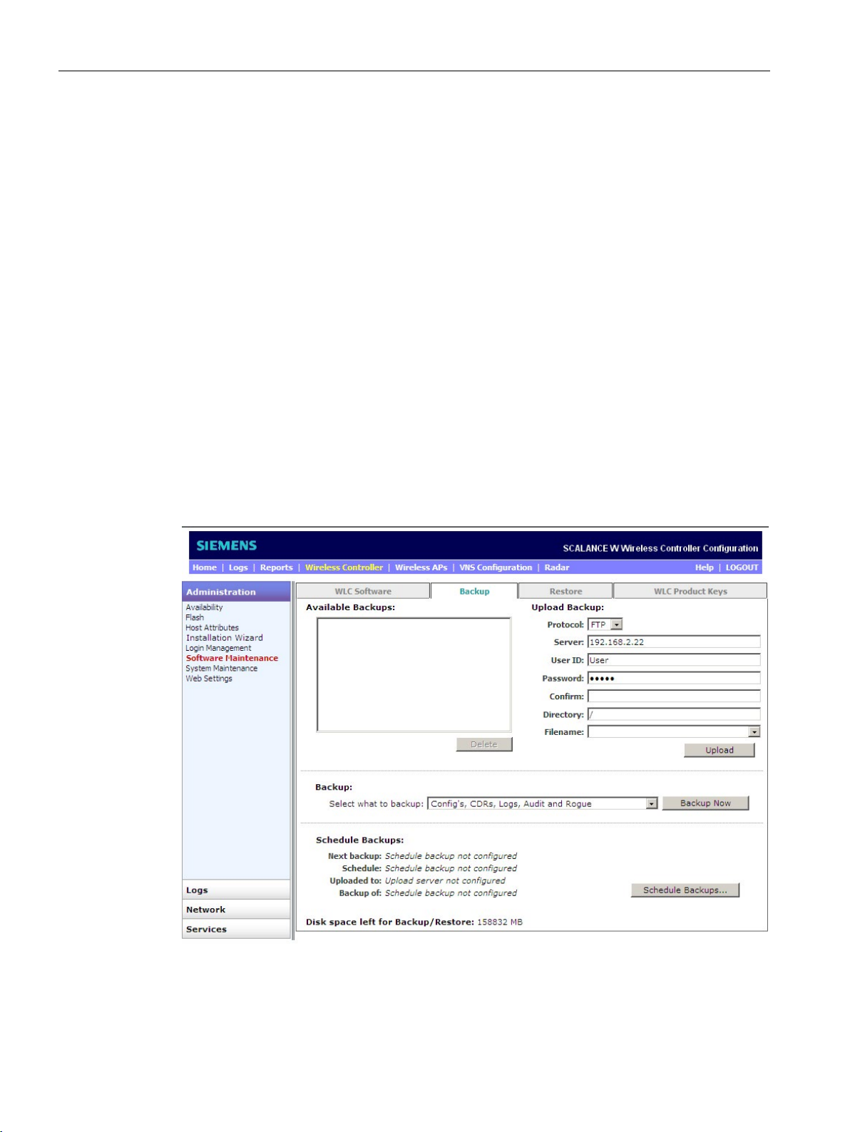
Optional configuration
7.3
Data backup
Introduction
"Backup" configuration page
7.3 Data backup
With the WBM you can save the following data as a backup and download it to a backup
server:
● Configurations
● CDRs (Call Data Records)
● Logs
● Audits
● Rogue APs
You can store the backup on a hard disk, FTP or SCP server.
To open the "Backup" configuration page, select the menu command "Wireless Controller >
Administration > Software Maintenance" and select the "Backup" tab. The following window
opens:
Figure 7-3 Software Maintenance - Backup
SCALANCE WLC711
84 Getting Started, 04/2016, C79000-G8976-C269-07
Page 85

Optional configuration
Available Backups
Backup
"Select what to backup" drop-down list
"Backup Now" button
Note
Note that the files ".work" and ".dat" are included in t
Upload Backup
"Protocol" drop-down list
"Server" input box
"User ID" input box
7.3 Data backup
This display box shows the backups that have already been created as a ZIP file.
To delete a backup, select the entry to be deleted and click the "Delete" button.
In this section, you create backups.
Select what you want to back up from the drop-down list:
● Config's, CDRs, Logs, Audit and Rogue
● Configurations only
● CDRs only
● Logs only
● Audit only
● Rogue only
To create the backup, click this button. A window now appears that confirms that the
backups have been successfully created. Close the window with the "Close" button.
The backup is saved and is listed in the "Available Backups" display box.
he ZIP file.
In this section, you upload backups.
Select one of the following protocol for data transmission from the drop-down list:
● FTP (File Transfer Protocol)
● SCP (Secure Copy Protocol)
Enter the IP address of the server on which the uploaded backup will be stored.
Enter the ID of the user with which the WLC711 logs on with the server.
SCALANCE WLC711
Getting Started, 04/2016, C79000-G8976-C269-07
85
Page 86

Optional configuration
"Password" input box
"Confirm" input box
"Directory" input box
"Filename" drop-down list
"Upload" button
Schedule Backup
7.3 Data backup
Enter the password with which the WLC711 logs on with the server.
To confirm the password, enter it again.
Enter the name of the directory in which the backup file will be saved.
From the drop-down list, select the zipped backup you want to upload.
To upload the zipped backup to the server, click the "Upload" button. The backup is now
saved on the server and can be used for a system restore.
This area lists the backups that have already been created in the form of a summary.
You also have the option of creating automatic backups. Here, certain backups can be
created automatically on a daily, weekly or monthly basis. To create automatic backups, click
the "Schedule Backup" button.
SCALANCE WLC711
86 Getting Started, 04/2016, C79000-G8976-C269-07
Page 87
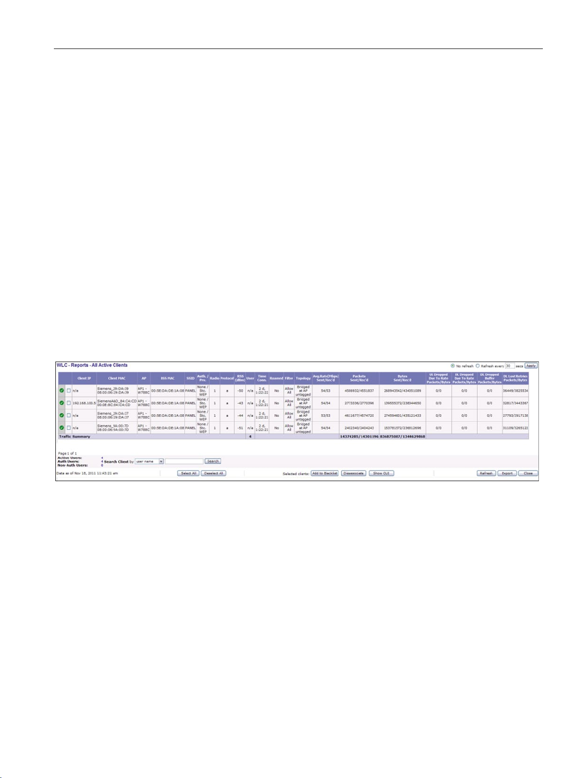
Optional configuration
7.4
Using reports
Introduction
All Active Clients
Wireless AP Availability
7.4 Using reports
With reports and displays, you can check statuses or even past events, for example:
● Transmission rate
● Connection of the access points
● Active clients
● Various statistics
● System information
The following sections describe the "All Active Clients" and "Wireless AP Availability" reports.
You will find further information in the SCALANCE WLC711 User Guide in the section
"Working with Reports and Displays".
To go to the "All Active Clients" page, select the "Reports > Clients > All Active Clients"
menu command.
Figure 7-4 Report - All Active Clients
This page shows you all the devices active in the WLAN. In the table, you can view various
connection properties for each device. These include, for example the IP and MAC address,
the authentication and encryption method or the average data rate (sending/receiving) of the
client.
To view the availability of the APs, open the "Wireless AP Availability" page with the menu
command "Reports > Wireless AP Availability".
The following window opens:
SCALANCE WLC711
Getting Started, 04/2016, C79000-G8976-C269-07
87
Page 88
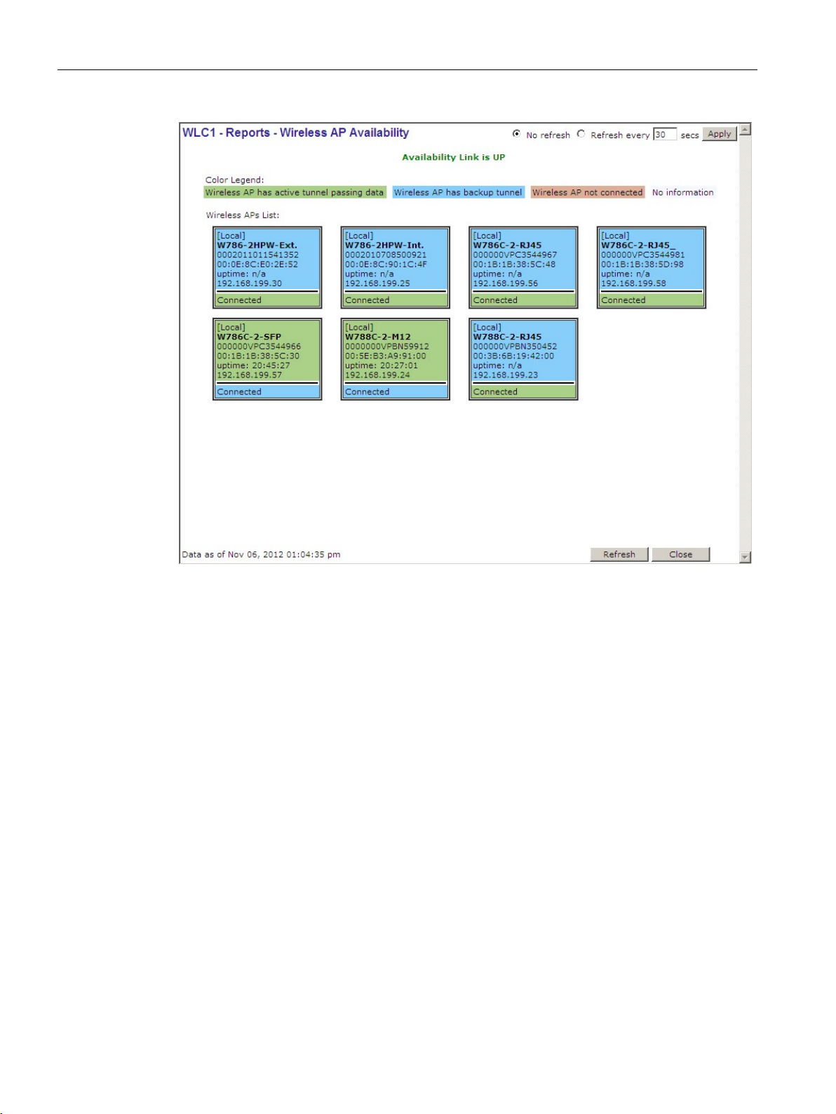
Optional configuration
7.4 Using reports
Figure 7-5 Example: Reports - Wireless AP Availability
If "Availability Link is UP" is displayed above the list, there is an active fault-tolerant
connection to a second WLC. If "Availability not configured" is displayed above the list, there
is no fault-tolerant connection to a second WLC. Check the configuration for errors and
eliminate them.
Each AP is represented by a colored box. The report uses the following colors to display the
status of the connection:
● Green
The AP has established an active connection.
● Blue
The AP has established a backup connection to a second WLC in fault-tolerant mode.
● Red
The AP is not connected.
You will find further information in the "SCALANCE WLC711" User Guide.
SCALANCE WLC711
88 Getting Started, 04/2016, C79000-G8976-C269-07
Page 89

Optional configuration
7.5
Using policies
Introduction
Non-authenticated default policy
Authenticated default policy
"Policies" configuration page
Example
7.5 Using policies
A policy is a collection of rules (permissions and prohibitions) that decide how WLAN clients
can act in the WLAN. A VNS always has two policies. By default, the policy for authenticated
users corresponds to the policy for non-authenticated users.
The following different types of policy are available:
●
This policy must exist. It is used for the data traffic of all non-authenticated clients.
●
This policy must exist. It is used for the data traffic of all clients that have already been
authenticated.
To open the "Policies" configuration page, select the "VNS Configuration > Policies" menu
command.
Below you will find an explanation of how you create a policy for non-authenticated clients
based on an example.
SCALANCE WLC711
Getting Started, 04/2016, C79000-G8976-C269-07
89
Page 90
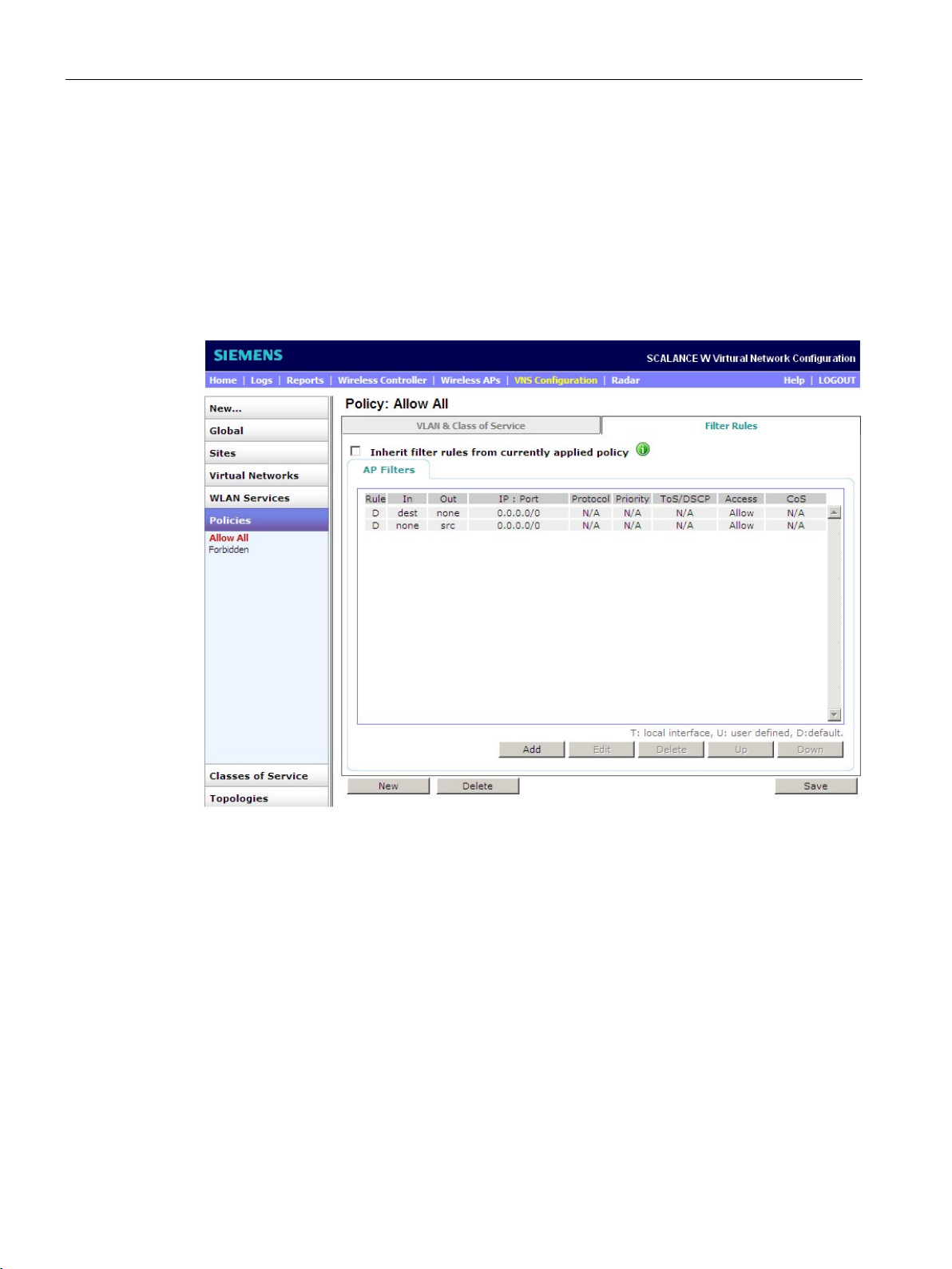
Optional configuration
7.5 Using policies
Follow these steps during configuration:
1. To create a new policy, click the "New" button.
2. Link the policy to a topology by selecting the topology from the "Assigned Topology" dropdown list. If you are uncertain which topology the policy should be linked to, leave the
entry set to "No Change".
3. Go to the "Filter Rules" tab. Depending on the function and the topology with which the
policy will be used, "AP Filtering" needs to be enabled. This must be enabled for "Bridge
at AP" topologies; for all other types of topology enabling this is optional.
Figure 7-6 Policies - Filter Rules
In the default setting, all communication is allowed (see screenshot). For non-authenticated
policies, it is advisable to prohibit all communication. This is achieved by selecting the
relevant filter rules and changing the access control to "Deny" using the "Edit" button.
If you nevertheless want to make certain destinations or address areas available in your
network, you can define these using "Add".
SCALANCE WLC711
90 Getting Started, 04/2016, C79000-G8976-C269-07
Page 91
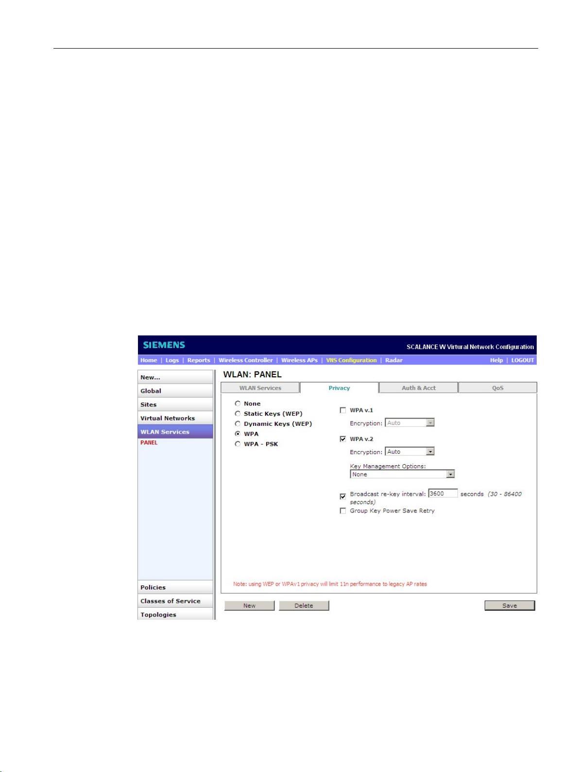
Optional configuration
7.6
Authentication via RADIUS server
Introduction
"Privacy" configuration page
RADIUS
7.6 Authentication via RADIUS server
A RADIUS server is a central authentication server that checks client logons using
certificates or user name and password. The advantage compared with WPA-/WPA2-PSK is
that each WLAN client has its own unique identifier.
To open the "Privacy" configuration page, select the menu command "VNS Configuration >
WLAN Services" and select the "Privacy" tab. With this page, you can create an automatic or
static key.
With the following setting, a WPA key is created automatically for each client:
Figure 7-7 WLAN Services - Privacy
SCALANCE WLC711
Getting Started, 04/2016, C79000-G8976-C269-07
91
Page 92
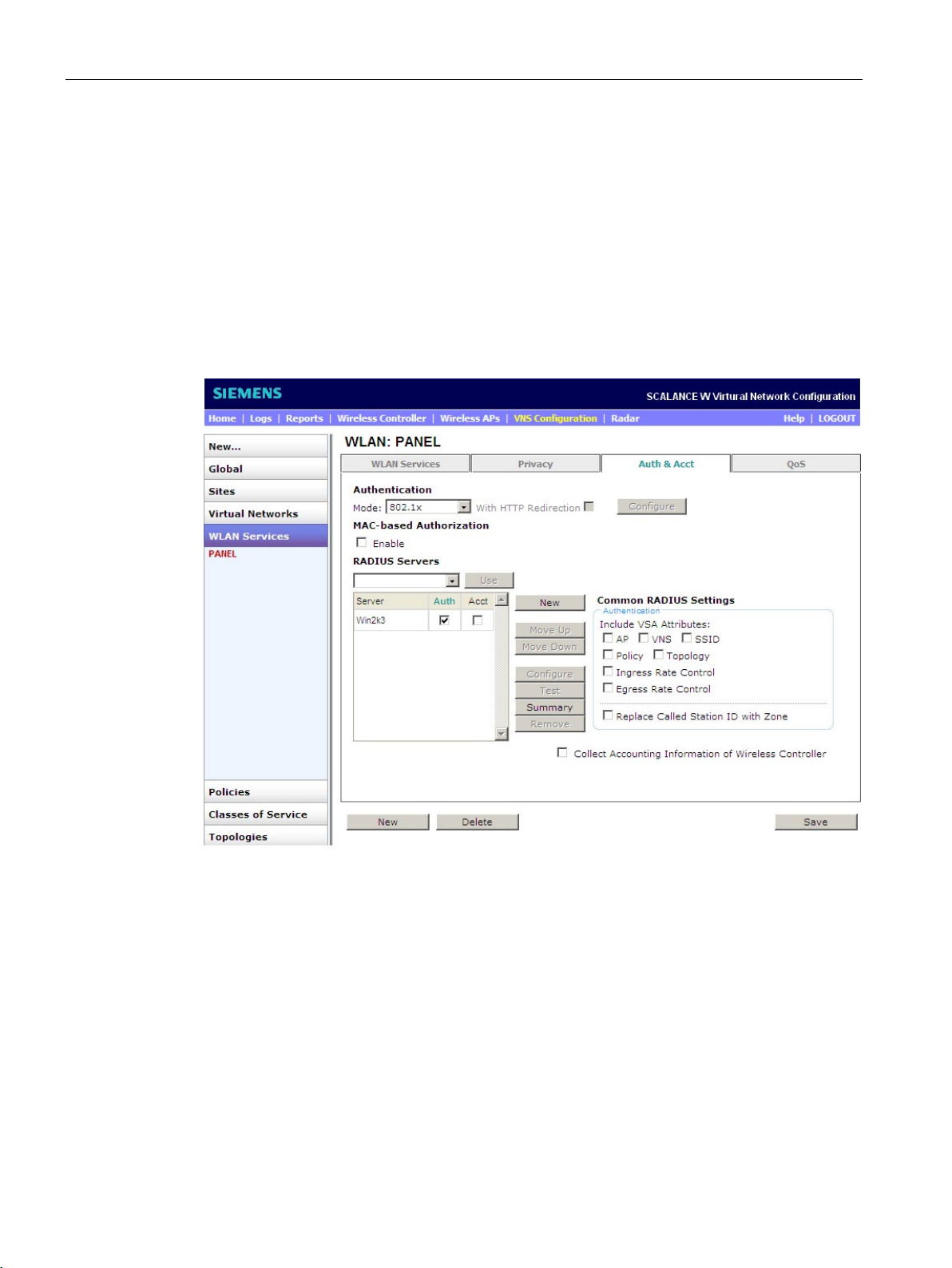
Optional configuration
Procedure
7.6 Authentication via RADIUS server
Follow these steps during configuration:
1. Select the "WPA" check box.
2. Select the "WPAv.2" check box.
3. Select the entry "Auto" from the "Encryption" drop-down list.
4. Select the "Broadcast re-key interval" check box and enter "3600" in the input box.
5. To save your changes, click the "Save" button.
The following window opens:
Figure 7-8 WLAN Services - Auth & Acct
6. To enable RADIUS, select the entry "802.1x" from the drop-down list.
You will find information about the RADIUS server in the SCALANCE WLC711 User
Guide in the section "VNS Global Settings".
7. To save your changes, click the "Save" button.
SCALANCE WLC711
92 Getting Started, 04/2016, C79000-G8976-C269-07
Page 93
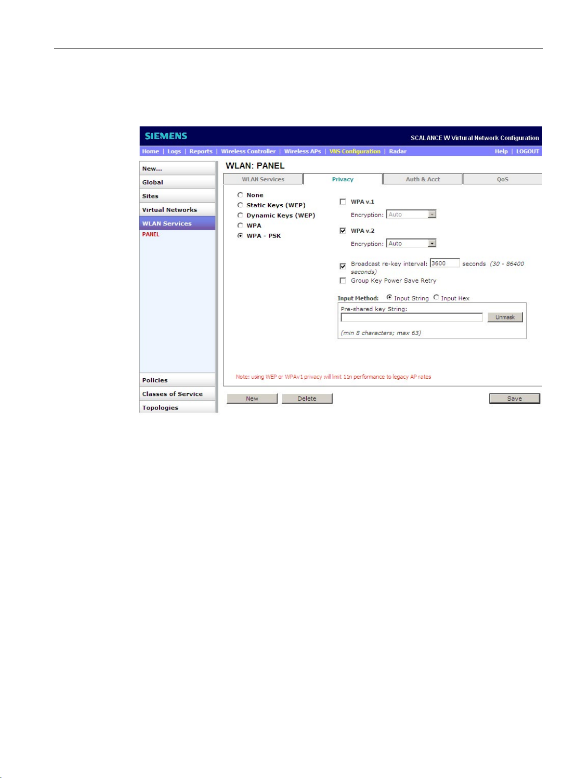
Optional configuration
WPA2-PSK
Procedure
7.6 Authentication via RADIUS server
With the following setting, a static WPA key is created for each client:
Figure 7-9 WLAN Services - Privacy
Follow these steps during configuration:
1. Select the "WPA - PSK" check box.
2. Select the "WPAv.2" check box.
3. Select the "Broadcast re-key interval" check box and enter "3600" in the input box.
4. To enter the WPA key as a string, select the "Input String" check box.
5. Enter a secure WPA key as a a string in the "Pre-shared key String" input box.
Remember that the WPA key must include a minimum of eight characters.
6. To save your changes, click the "Save" button.
SCALANCE WLC711
Getting Started, 04/2016, C79000-G8976-C269-07
93
Page 94
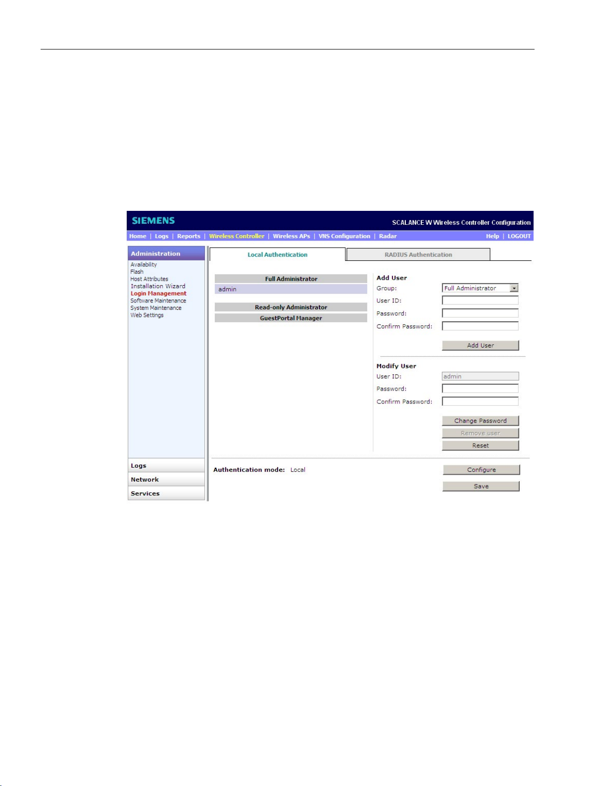
Optional configuration
7.7
User configuration
"Local Authentication" configuration page
Changing user data
7.7 User configuration
This section contains information about changing user data, creating new users or deleting
existing users.
To open the "Local Authentication" configuration page, select the "Wireless Controller >
Login Management" menu command. The following window opens:
Figure 7-10 Login Management - Local Authentication
To change the data of a user, follow the steps below:
1. Choose the user to be modified in the list.
2. In the section "Modify User", enter the new password in the "Password" input box.
3. Confirm the new password in the "Modify User" section by entering it again in the
"Confirm Password" input box. To save the new password, click the "Change Password"
button.
4. To save the configuration, click the "Save" button.
SCALANCE WLC711
94 Getting Started, 04/2016, C79000-G8976-C269-07
Page 95

Optional configuration
Adding users
Full Administrator
Read-only Administrator
GuestPortal Manager
Delete user
7.7 User configuration
To create new user, first select an authorization level from the "Group" drop-down list in the
"Add User" section. The following authorization levels are available:
●
With this authorization, the user creates the entire configuration on the WLC and on the
"GuestPortal" page.
●
With this authorization, the user only reads the configurations of the WLC and
"GuestPortal" page. With this authorization, the user does not make any changes.
●
With this authorization, the user only logs on to a special "GuestPortal" page with which
the user has restricted access.
You will find further information in the "SCALANCE WLC711" User Guide.
To delete a user, follow the steps below:
1. Select the user to be deleted from the list.
2. Click the "Remove user" button in the "Modify User" section.
The user is now deleted.
SCALANCE WLC711
Getting Started, 04/2016, C79000-G8976-C269-07
95
Page 96

Optional configuration
7.7 User configuration
SCALANCE WLC711
96 Getting Started, 04/2016, C79000-G8976-C269-07
Page 97

2
3
4
A
B
C
D
E
20MHz, 50
3rd Party, 36
Bandwidth, 50, 71
Basic configuration, 20
Basic Settings, 63, 73
Bridged at AP, 14, 32, 70, 73
Bridged at WLC, 14, 17, 61, 63
Broadcast re-key interval, 66, 74
BSS info, 50
40MHz, 50
Access points
All APs, 45
Allow all Wireless APs to connect, 40
Allow only approved Wireless APs to connect, 40
AP Default Settings, 41, 42
AP Environment, 47
AP Multi-Edit, 58
AP Properties, 43, 46
AP Registration, 38, 39
Configuring access points at the same time, 59
Wireless AP Availability, 87
Activation key, 79, 81
Active Clients, 47
Address Range, 64
Admin Mode, 50
AES, 7
All Active Clients, 87
All Non-DFS Channels, 52
Antennas
Antenna Selection, 52
Antenna types, 48
AP Registration, 39
Application Version, 47
Area ID, 30
Authentication Mode, 63, 73
Auto Tx Power Ctrl (ATPC), 51
Auto Tx Power Ctrl Adjust, 52
Backup, 84
Captive portal, 17
Category, 63, 72
Changing the password, 34
Channel
All Channels, 52
Channel Plan, 52
Channel Width, 50
Current Channel, 51
Last Requested Channel, 51
Request New Channel, 51
Channel bonding, 50
CLI, 82
CLI commands, 22
Command Line Interface, 82
Common Configuration, 42
Country, 44, 47
Current Tx Power Level, 51
Custom, 52
Data loss, 21
Data port, 17
Description, 47
DHCP, 17, 37, 42, 56, 57, 64
Discovery Timers, 40
Number of retries:Delay between retries, 40
Encryption, 66, 74
esa0, 36, 63, 71
Ethernet
Ethernet Mode, 56
Ethernet Port, 56
Ethernet Speed, 56
SCALANCE WLC711
Getting Started, 04/2016, C79000-G8976-C269-07
97
Page 98

Index
F
G
H
I
L
M
N
O
P
R
S
Filter ID, 65
Filtering, 65
Full duplex, 56
Gateway, 29, 56
Glossary, 4
Guard Interval, 51
Half duplex, 56
Hardware
Hardware Types, 58
Hardware Version, 47
Installing hardware, 18
Host Name, 46
Hyper Terminal, 82
IEEE standard
IEEE standard 802.11, 49
IEEE standard 802.11a/h, 50
IEEE standard 802.11a/n, 48
IEEE standard 802.11b/g/n, 48
IEEE standard 802.11n, 50, 51, 66, 67, 74, 75
IEEE standard 802.1x, 57
Initial logon, 20
Input Method, 66, 74
Interface IP, 37
IP address, 19, 43
Reading the IP address, 82
Setting the IP address, 83
IP Address, 27, 28, 31, 56
Layer 2, 36
Layer 3, 37
Lease time, 64
LLDP, 43
Local Authentication, 94
Local DHCP server, 64
Location, 46
Logon page, 19
MAC mode, 62, 71
Management port, 28, 33
Management Traffic, 38
Man-in-the-middle attacks, 7
Mask, 37
Max Tx Power, 51
Min Tx Power, 51
Mobility, 32
MTU, 38
Multi-edit, 58
Netmask, 27, 28, 56
NTP, 26, 32
OSPF, 30
Password, 20, 66, 74
Physical 1, 36
PNIO, 17
Policies, 63, 72
Policy, 89
Power supply, 16
Privacy, 66, 74, 91
Radio
Radio 1, 49, 49, 67, 75
Radio 2, 49, 54, 67, 75
Radio Assignment, 67, 75
Radio Mode, 50
Radio Settings, 44
RADIUS, 17, 31, 91
Reports, 87
RF Domain, 51
Roaming, 41, 62
Run local NTP Server, 26
Schedule Backup, 86
Secure Cluster, 41
SCALANCE WLC711
98 Getting Started, 04/2016, C79000-G8976-C269-07
Page 99

Index
T
U
V
W
Security Mode, 40
Security properties, 39
Serial #, 46
Serial interface, 82
Server Alias, 31
Service Location Protocol, 41
Set time, 26
Shared Secret, 31
SIMATIC NET glossary, 4
SNMP, 29
SNMPv3, 7
SSH Access, 41
SSID, 32, 63, 73
Static Configuration, 55
Static Values, 56
Status
Approved, 47
Pending, 47
Success, 69, 77
Summary, 68, 76
Syslog server, 30
System Maintenance, 21
Tagged, 36
Time Settings, 25
Topology
Topologies, 63, 72
Topology, 35, 47
Topology Configuration, 26
Tunnel MTU, 56
VNS, 89
Default VNS, 32
VNS Creation Wizard, 62, 72
Voice, 17
W78xC, 41, 43
Wi-Fi Multimedia, 67, 75
Wireless Controller Search List, 42, 57
WLAN, 63
WLAN Assignment, 48
WLAN Name, 48
WLAN service, 17
WLAN settings, 73
WLAN settings:WLAN settings, 63
WLAN type, 17
WMM, 67, 75
WPA, 91
WPA v.2, 66, 74
WPA-PSK, 66, 74
WPA-PSK Key, 32
WPA2, 7
WPA2-PSK, 91, 93
Untagged, 36, 55
User
Adding users, 95
Changing user data, 94
Delete user, 95
User name, 20
V2c, 29
V3, 29
View SLP Registration, 41
VLAN
VLAN ID, 26, 36, 55, 63
VLAN settings, 62
VLAN Settings, 55
SCALANCE WLC711
Getting Started, 04/2016, C79000-G8976-C269-07
99
Page 100

Index
SCALANCE WLC711
100 Getting Started, 04/2016, C79000-G8976-C269-07
 Loading...