

Page 1

___________________
___________________
___________________
___________________
___________________
___________________
___________________
___________________
___________________
___________________
___________________
___________________
SIMATIC NET
S7-400 - Industrial Ethernet
CP 443-1 RNA
Manual
Manual Part B
03/2019
C79000
Preface
Application and functions
1
Performance data
2
Requirements for use
3
LEDs
4
Installation, connecting up,
commissioning
5
Configuration and operation
6
Upkeep and maintenance
7
Technical specifications
8
Approvals
9
PRP-compatible devices
A
Documentation references
B
-G8976-C299-04
Page 2

Siemens AG
Division Process Industries and Drives
Postfach 48 48
90026 NÜRNBERG
GERMANY
C79000-G8976-C299-04
Ⓟ
Copyright © Siemens AG 2013 - 2019.
All rights reserved
Legal information
Warning notice system
DANGER
indicates that death or severe personal injury will result if proper precautions are not taken.
WARNING
indicates that death or severe personal injury may result if proper precautions are not taken.
CAUTION
indicates that minor personal injury can result if proper precautions are not taken.
NOTICE
indicates that property damage can result if proper precautions are not taken.
Qualified Personnel
personnel qualified
Proper use of Siemens products
WARNING
Siemens products may only be used for the applications described in the catalog and in the relevant technical
ambient conditions must be complied with. The information in the relevant documentation must be observed.
Trademarks
Disclaimer of Liability
This manual contains notices you have to observe in order to ensure your personal safety, as well as to prevent
damage to property. The notices referring to your personal safety are highlighted in the manual by a safety alert
symbol, notices referring only to property damage have no safety alert symbol. These notices shown below are
graded according to the degree of danger.
If more than one degree of danger is present, the warning notice representing the highest degree of danger will
be used. A notice warning of injury to persons with a safety alert symbol may also include a warning relating to
property damage.
The product/system described in this documentation may be operated only by
task in accordance with the relevant documentation, in particular its warning notices and safety instructions.
Qualified personnel are those who, based on their training and experience, are capable of identifying risks and
avoiding potential hazards when working with these products/systems.
Note the following:
documentation. If products and components from other manufacturers are used, these must be recommended
or approved by Siemens. Proper transport, storage, installation, assembly, commissioning, operation and
maintenance are required to ensure that the products operate safely and without any problems. The permissible
All names identified by ® are registered trademarks of Siemens AG. The remaining trademarks in this publication
may be trademarks whose use by third parties for their own purposes could violate the rights of the owner.
We have reviewed the contents of this publication to ensure consistency with the hardware and software
described. Since variance cannot be precluded entirely, we cannot guarantee full consistency. However, the
information in this publication is reviewed regularly and any necessary corrections are included in subsequent
editions.
for the specific
03/2019 Subject to change
Page 3
Preface
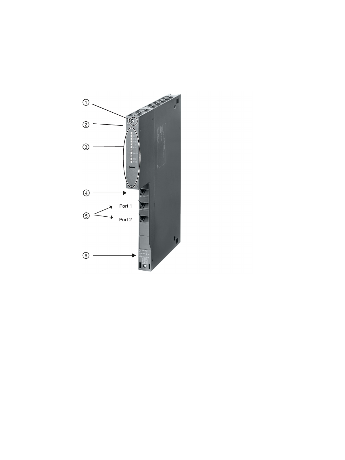
Legend:
①
X = placeholder for hardware product version
②
Firmware version
③
LEDs
④
Ethernet interface: Interface X1P1 with 1 x 8-pin RJ-45 jack
⑤
Designed for a redundant subnet
⑥
Label with MAC addresses
Validity and product names
RNA interface: Ports X2P1 / X2P2 with 2 x 8-pin RJ-45 jacks
Figure 1 CP 443-1 RNA
This description contains information on the following product
CP 443-1 RNA
Order number 6GK7 443-1RX00-0XE0
Hardware product version 1
CP 443-1 RNA
Manual, 03/2019, C79000-G8976-C299-04
3
Page 4

Preface
Note
Names
•
•
New in this release
Replaced manual issue
Structure of the documentation
Current version of the manual and Information on the Internet
Firmware version V1.4.1
Communications processor for SIMATIC S7-400 / S7-400H
In this document, the term "CP" is used instead of the full product name.
The name STEP 7 is used for the configuration tool instead of the names STEP 7 V5.5
and STEP 7 Professional.
● New ATEX/IECEx approval
● Editorial revision
Replaced manual edition 7/2017
The documentation for this device consists of the following parts:
● Manual Part A: Configuration manual "Configuring and Commissioning S7CPs for
Industrial Ethernet", see references /1/ (Page 67).
● Manual Part B: Manual "CP 443-1 RNA" (this manual)
● Program blocks for SIMATIC NET S7 CPs - programming manual, see references /4/
(Page 68)
Contains the detailed description of the program blocks for the following services:
– Open communications services
– Access coordination with FETCH/WRITE
– Connection and system diagnostics
You will find the current version of this document and further information (e.g. FAQs) on
using the CP on the Internet at the following address:
Link: (https://support.industry.siemens.com/cs/ww/en/ps/15355)
Select the appropriate entry type in the filter settings.
CP 443-1 RNA
4 Manual, 03/2019, C79000-G8976-C299-04
Page 5

Preface
CP documentation in the Manual Collection (order no. A5E00069051)
Compatibility with other modules - service and maintenance
Note
Read the information regarding extended functions and restrictions in section
modules used with CP 443
Address label: Unique MAC address preset for the CP
License conditions
Note
Open source software
Read the license conditions for open source software carefully before using the product. The
acceptance of the disclaimers of liability and warranty it contains is a clear precondition of
the use of open source software.
You will find the license condition
following file name:
OSS_CP44x1RNA_86.pdf
Firmware
The "SIMATIC NET Manual Collection" DVD contains the device manuals and descriptions
of all SIMATIC NET products current at the time it was created. It is updated at regular
intervals.
Replacing the
-1 RNA (Page 52) of this manual!
The CP is supplied with a total of 2 default MAC addresses with the following assignment:
● Ethernet interface
● RNA interface
The two MAC addresses of the Ethernet interface and the RNA interface are printed on the
housing.
If you configure a MAC address (ISO transport connections), we recommend that you use
the MAC address of the relevant interface printed on the module for module configuration!
● This ensures that you assign a unique MAC address in the subnet!
● If you replace a module, the MAC address of the predecessor is adopted when you load
the configuration data; configured ISO transport connections remain operable.
s on the same data medium as this manual under the
CP 443-1 RNA
Manual, 03/2019, C79000-G8976-C299-04
The firmware is signed and encrypted. This ensures that only firmware created by Siemens
can be downloaded to the device.
5
Page 6

Preface
Security information
Recycling and disposal
SIMATIC NET glossary
Training, Service & Support
Siemens provides products and solutions with industrial security functions that support the
secure operation of plants, systems, machines and networks.
In order to protect plants, systems, machines and networks against cyber threats, it is
necessary to implement – and continuously maintain – a holistic, state-of-the-art industrial
security concept. Siemens’ products and solutions only form one element of such a concept.
Customer is responsible to prevent unauthorized access to its plants, systems, machines
and networks. Systems, machines and components should only be connected to the
enterprise network or the internet if and to the extent necessary and with appropriate security
measures (e.g. use of firewalls and network segmentation) in place.
Additionally, Siemens’ guidance on appropriate security measures should be taken into
account. For more information about industrial security, please visit
Link: (http://www.siemens.com/industrialsecurity)
Siemens’ products and solutions undergo continuous development to make them more
secure. Siemens strongly recommends to apply product updates as soon as available and to
always use the latest product versions. Use of product versions that are no longer supported,
and failure to apply latest updates may increase customer’s exposure to cyber threats.
To stay informed about product updates, subscribe to the Siemens Industrial Security RSS
Feed under
Link: (http://www.siemens.com/industrialsecurity).
The product is low in pollutants, can be recycled and meets the requirements of the WEEE
directive 2012/19/EU "Waste Electrical and Electronic Equipment".
Do not dispose of the product at public disposal sites. For environmentally friendly recycling
and the disposal of your old device contact a certified disposal company for electronic scrap
or your Siemens contact.
Keep to the local regulations.
You will find information on returning the product on the Internet pages of Siemens Industry
Online Support:
Link: (https://support.industry.siemens.com/cs/ww/en/view/109479891)
Explanations of many of the specialist terms used in this documentation can be found in the
SIMATIC NET glossary.
You will find the SIMATIC NET glossary on the Internet at the following address:
Link: (https://support.industry.siemens.com/cs/ww/en/view/50305045)
You will find information on training, service and support in the multilanguage document
"DC_support_99.pdf" on the Internet pages of Siemens Industry Online Support:
Link: (https://support.industry.siemens.com/cs/ww/en/view/38652101)
CP 443-1 RNA
6 Manual, 03/2019, C79000-G8976-C299-04
Page 7

Table of contents
Preface ................................................................................................................................................... 3
1 Application and functions ........................................................................................................................ 9
2 Performance data ................................................................................................................................. 17
3 Requirements for use ............................................................................................................................ 23
4 LEDs..................................................................................................................................................... 27
5 Installation, connecting up, commissioning ............................................................................................ 31
6 Configuration and operation .................................................................................................................. 37
1.1 Properties of the CP .................................................................................................................. 9
1.2 Communication services ......................................................................................................... 10
1.3 Network topology with redundancy (PRP) .............................................................................. 11
1.4 Further services and characteristics of the CP ....................................................................... 15
2.1 General characteristic data ..................................................................................................... 17
2.2 Characteristics of S7 communication ..................................................................................... 17
2.3 SEND/RECEIVE interface ...................................................................................................... 18
2.3.1 Characteristic data .................................................................................................................. 18
2.3.2 Number of simultaneous SEND/RECEIVE calls ..................................................................... 19
2.4 Characteristics of open TCP/IP communication ..................................................................... 21
2.5 Characteristic data of TCP connections for HTTP .................................................................. 21
3.1 Configuration limits ................................................................................................................. 23
3.2 System environment ............................................................................................................... 23
3.3 Project engineering ................................................................................................................. 25
3.4 Programming .......................................................................................................................... 25
5.1 Important notes on using the device ....................................................................................... 31
5.1.1 Notices on use in hazardous areas ........................................................................................ 31
5.1.2 Notices on use in hazardous areas according to ATEX / IECEx ............................................ 32
5.1.3 Notices on use in hazardous areas according to UL HazLoc ................................................. 33
5.2 Installation - procedure ........................................................................................................... 33
5.3 Commissioning - procedure .................................................................................................... 34
5.4 Replacing a module without a programming device ............................................................... 35
5.5 Controlling the mode ............................................................................................................... 36
6.1 Security recommendations ..................................................................................................... 37
6.2 Switching over interfaces ........................................................................................................ 40
6.3 Memory reset / reset to factory defaults ................................................................................. 40
CP 443-1 RNA
Manual, 03/2019, C79000-G8976-C299-04
7
Page 8

Table of contents
7 Upkeep and maintenance ..................................................................................................................... 51
8 Technical specifications ........................................................................................................................ 55
9 Approvals ............................................................................................................................................. 57
A PRP-compatible devices ....................................................................................................................... 63
B Documentation references .................................................................................................................... 67
Index .................................................................................................................................................... 71
6.4 Network settings..................................................................................................................... 42
6.4.1 Reserved MAC address ......................................................................................................... 42
6.4.2 Transmission properties of the Ethernet and RNA interfaces ............................................... 42
6.5 IP configuration ...................................................................................................................... 44
6.5.1 Setting the IP address ............................................................................................................ 44
6.5.2 Detecting duplicate IP addressing in the network .................................................................. 44
6.6 Time-of-day synchronization .................................................................................................. 45
6.7 Recommendation for use with a high communications load ................................................. 45
6.8 SNMP agent ........................................................................................................................... 46
6.9 Interface in the user program ................................................................................................. 48
6.9.1 Call interface for open communications services SEND/RECV ............................................ 48
6.9.2 Open TCP/IP communication ................................................................................................ 49
6.10 Ping: Permitted length of ICMP packets ................................................................................ 50
6.11 Communication in PRP mode ................................................................................................ 50
7.1 Loading new firmware ............................................................................................................ 51
7.2 Replacing the modules used with CP 443-1 RNA ................................................................. 52
B.1 Introduction to the documentation.......................................................................................... 67
B.2 On configuring, commissioning and using the CP ................................................................. 67
B.2.1 /1/ ........................................................................................................................................... 67
B.3 For configuration with STEP 7 / NCM S7 .............................................................................. 68
B.3.1 /2/ ........................................................................................................................................... 68
B.3.2 /3/ ........................................................................................................................................... 68
B.4 On programming (S7 CPs / OPC).......................................................................................... 68
B.4.1 /4/ ........................................................................................................................................... 68
B.4.2 /5/ ........................................................................................................................................... 68
B.4.3 /6/ ........................................................................................................................................... 69
B.4.4 /7/ ........................................................................................................................................... 69
B.4.5 /8/ ........................................................................................................................................... 69
B.4.6 /9/ ........................................................................................................................................... 69
B.5 S7 CPs On installing and commissioning the CP .................................................................. 70
B.5.1 /10/ ......................................................................................................................................... 70
B.6 On setting up and operating an Industrial Ethernet network ................................................. 70
B.6.1 /11/ ......................................................................................................................................... 70
CP 443-1 RNA
8 Manual, 03/2019, C79000-G8976-C299-04
Page 9

1
1.1
Properties of the CP
Application
The CP has the following interfaces:
Note
Interfaces can only operated as alternatives
The Ethernet interface or the RNA interface can only be enabled as alternatives (one or the
other). Simultaneous use of both interfaces is not possible. These are activated during
configuration with STEP 7. Note further information in the section
(Page
The CP is intended for use in an S7400 or S7400H (faulttolerant) automation system. It
allows the S7400 / S7400H to be connected to Industrial Ethernet.
● Ethernet interface
The CP has a 100 Mbps Ethernet interface. The Ethernet interface can be used as an
alternative to the RNA interface. The Ethernet interface can, for example, be used to
connect to a PG/PC or to a higherlevel company network.
For special situations, each port can be set to a fixed mode manually using STEP 7, for
example 10 or 100 Mbps half duplex / full duplex.
● RNA interface
The RNA interface has 2 ports. These two ports are used as follows:
– PRP mode with both ports as a redundancy solution
– Port 1 as the only used port of the RNA interface with 100 Mbps full duplex (port 2 is
disabled)
The RNA interface only supports the "automatic setting" mode with 100 Mbps full duplex.
The communications partner must use the same settings.
Each port supports autocrossing and autonegotiation and is equipped with a combined
RXD/TXD / LINK dual LED for simple diagnostics.
Switching over interfaces
40)
CP 443-1 RNA
Manual, 03/2019, C79000-G8976-C299-04
9
Page 10

Application and functions
①
Connection to port X1P1 of the Ethernet interface (ISO transport)
②
Connection of the RNA interface to a PRP network
③
Connection to port X2P1 of the RNA interface (ISO transport / ISO-on-TCP / TCP)
1.2
Communication services
S7 communication with the following functions:
Open communication services with the following functions:
1.1 Properties of the CP
Figure 1-1 CP 443-1 RNA - connection variants
Depending on the interface being used, the CP supports the following communications
services:
●
– PG functions;
– Operator monitoring and control functions;
– Data exchange over S7 connections.
●
– SEND/RECEIVE interface over ISO transport connections;
– SEND/RECEIVE interface over TCP connections, ISOonTCP and UDP connections;
With the SEND/RECEIVE interface via TCP connections, the CP supports the socket
interface to TCP/IP available on practically every end system.
UDP frame buffering on the CP can be disabled during configuration. When
necessary, this allows you to achieve a shorter reaction time between the arrival of a
UDP frame and its evaluation on the CPU.
– Multicast over UDP connection
The multicast mode is made possible by selecting a suitable IP address when
configuring connections.
– FETCH/WRITE services (server services; corresponding to S5 protocol) via ISO
transport connections, ISOonTCP connections and TCP connections;
Here, the SIMATIC S7400 with the CP is always the server (passive connection
establishment) while the fetch or write access (client function with active connection
CP 443-1 RNA
10 Manual, 03/2019, C79000-G8976-C299-04
Page 11

Application and functions
Open TCP/IP communication
Interfaces used and communications services
Communications service
Ethernet interface
RNA interface
functions (ISO)
x x
- x
Data exchange over S7 connections (ISO)
x
x
Data exchange over S7 connections (TCP)
-
x
ISO transport connections
x
x
tions
- x
Multicast over UDP connection
-
x
FETCH/WRITE services (ISO)
x
x
FETCH/WRITE services (RFC, TCP)
-
x
nication
- x
Time of day
NTP mode and SIMATIC mode
-
x
via ISO x x
via TCP - x
1.3
Network topology with redundancy (PRP)
Redundant Network Access (RNA)
1.3 Network topology with redundancy (PRP)
establishment) is always initiated by a SIMATIC S5 or a device from another range /
PC.
– LOCK/UNLOCK with FETCH/WRITE services (CPUdependent; see section
Requirements for use (Page 23));
●
Open TCP/IP communication provides a program interface for the transfer of connectionoriented and connectionless services. The establishment and termination of connections
is initiated here only via the "dynamic" program interface.
STEP 7 provides a UDT for the connection parameter assignment as well as four FBs for
high-speed data exchange.
The CP supports communication via ISO-on-TCP connections for this interface.
The following table provides an overview of the services available at the interfaces.
S7 communication PG functions; operator control and monitoring
PG functions; operator control and monitoring
functions (ISO-on-TCP)
Open communications
services using
SEND/RECEIVE interface
Open TCP/IP commu-
H connections
TCP connections, ISOonTCP and UDP connec-
In Siemens Industry, Redundant Network Access (RNA) stands for devices and software that
support the redundancy protocol "Parallel Redundancy Protocol" (PRP). RNA allows the
connection of devices to redundant Ethernet network structures.
The product names of the RNA devices end with "RNA".
CP 443-1 RNA
Manual, 03/2019, C79000-G8976-C299-04
11
Page 12

Application and functions
Parallel Redundancy Protocol (PRP)
Communication with PRP
1.3 Network topology with redundancy (PRP)
Some devices of the SCALANCE X-200RNA product line also support the redundancy
protocol "High-availability Seamless Redundancy" (HSR).
The Parallel Redundancy Protocol (PRP) is a redundancy protocol for Ethernet networks. It
is specified in IEC 62439-3.
The areas of application of PRP are distributed applications with high reliability demands that
depend on the high availability of the network. Compared with classic fault-tolerant networks,
bumpless path redundancy is possible with PRP.
PRP has the advantage that it uses parallel, separate networks made up of standard
network components. End devices that use this method are connected to both networks via
two ports of an interface of the device or via a SCALANCE X-200RNA or a RUGGEDCOM
RS950G. This means that data of the end device can be transferred at the same time via
both networks. If a transmission path is interrupted, the data reaches the communications
partner via the second parallel path.
If a network is interrupted, communication can be maintained with PRP via the second
network without any interruption. Reconfiguration times required with the other redundancy
protocols (e.g. MRP) do not therefore apply.
An end device with PRP capability can be connected to redundant networks by using the
PRP protocol. An end device that does not have PRP capability can be connected to a
redundant network via a SCALANCE X-200RNA or RUGGEDCOM RS950G that does have
PRP capability. This means that PRP can also be used by end devices without PRP
capability.
Devices with PRP capability are located in two independent networks with the same MAC
and IP address.
PRP is only possible when two end devices are connected via two independent networks
(LAN A and LAN B).
Each end device is represented in both networks LAN A and LAN B with the same MAC and
IP address.
CP 443-1 RNA
12 Manual, 03/2019, C79000-G8976-C299-04
Page 13

Application and functions
Send
Received
Connecting up and cabling
Note
Cabling
Make sure that all the PRP ports of the nodes and the SCALANCE X204RNA /
RUGGEDCOM RS950G on LAN A and LAN B are connected correctly. A frame with the
identifier "LAN A" must be received at the corresponding port.
How is a redundant PRP network set up?
1.3 Network topology with redundancy (PRP)
PRP communication is handled using the following mechanisms:
●
An end device with PRP capability duplicates each frame to be sent on the PRP
interface. The two duplicates are sent via the 2 ports of the PRP interface via the two
separate networks LAN A and LAN B to the communications partner.
If the end device does not have PRP capability, the frame to be sent is duplicated by an
X-200RNA to which the end device is connected and sent via LAN A and LAN B to the
communications partner.
●
The two duplicates are received by an end device with PRP capability via LAN A and
LAN B on the two ports of the PRP interface.
If the end device does not have PRP capability, the receiving end device must be
preceded by an X-200RNA. The X-200RNA forwards the first frame to arrive to the
addressee. The second frame is discarded ((N-1) redundancy).
Each frame duplicate sent using the PRP mechanisms is given in identifier that specifies
whether it is sent via LAN A or LAN B.
The PRP ports of SIMATIC NET devices have the following identifiers. The CP ports are the
ports of the interface with PRP capability.
● Ports for connection to LAN A
– CPs: X2/P1
– SCALANCE X204RNA: PRP A
● Ports for connection to LAN B
– CPs: X2/P2
– SCALANCE X204RNA: PRP B
A network topology in which the Parallel Redundancy Protocol is used (PRP network)
consists of two separate Ethernet subnets. The structure of the two subnets does not need
to be identical.
CP 443-1 RNA
Manual, 03/2019, C79000-G8976-C299-04
13
Page 14
Application and functions
Example of a configuration for a PRP network
1.3 Network topology with redundancy (PRP)
A PRP network can be set up both with end devices with PRP capability as well as with
standard components. The following devices can be used:
● End devices with PRP capability (Double Attached Nodes PRP, Double Attached Node
implementing PRP, DANP), for example:
– CP 443-1 RNA
– PC with SOFTNET-IE RNA
– SIPROTEC protective devices with PRP capability
● Standard components (Singly Attached Nodes, SAN)
Standard components without PRP functionality, for example, can be connected to a PRP
network via SCALANCE X-200RNA or RuggedCom RS950G.
SANs can, however, also be connected to a PRP network without supporting the PRP
functionality.
All devices that are intended to use the PRP function in redundant networks must be able to
process frames with length of up to 1532 bytes (oversize frames). If this function is not
supported, data may be lost.
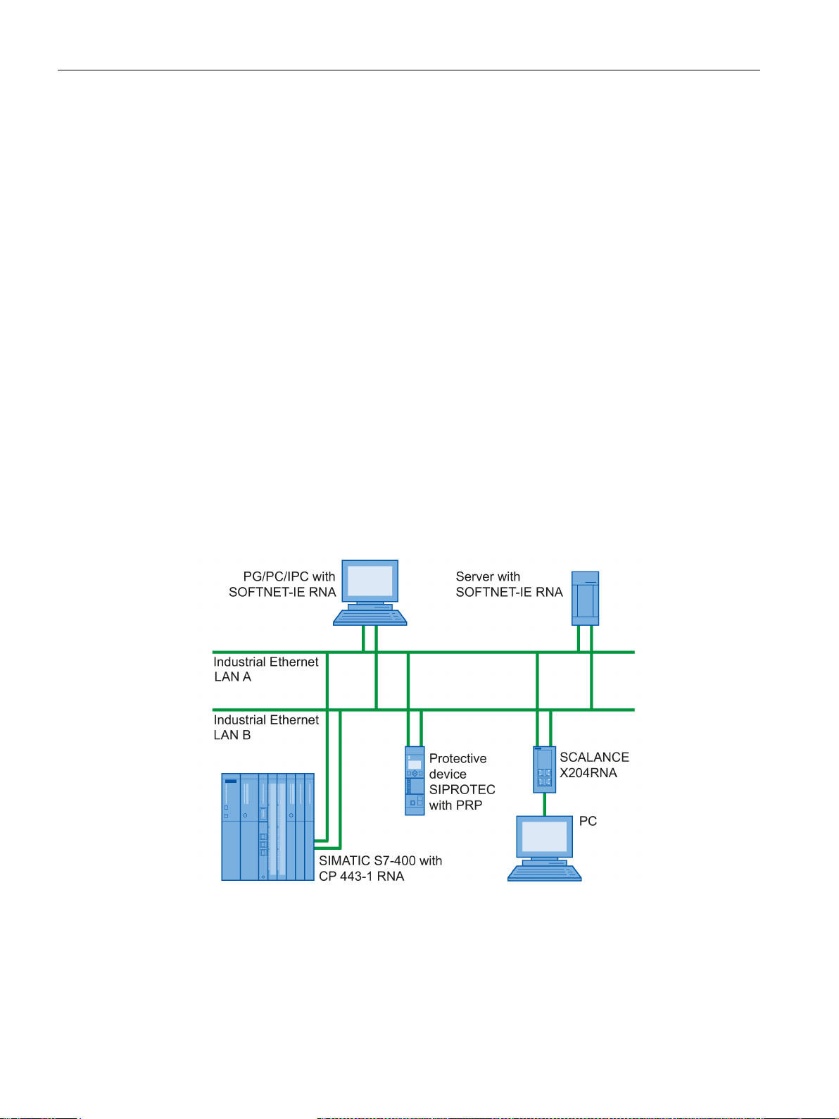
The following figure shows the options for connecting devices in a network topology in which
the Parallel Redundancy Protocol (PRP) is used.
Figure 1-2 Example of the configuration of a network topology with PRP
CP 443-1 RNA
14 Manual, 03/2019, C79000-G8976-C299-04
Page 15

Application and functions
1.4
Further services and characteristics of the CP
Timeofday synchronization over the RNA interface using the following configurable
modes:
Addressable with the factoryset MAC address
SNMP agent on the RNA interface
Module access protection
IP access protection on the RNA interface (IPACL)
Web diagnostics on the RNA interface
Diagnostics buffer extract request
1.4 Further services and characteristics of the CP
●
– SIMATIC mode
or
– NTP mode (NTP: Network Time Protocol)
●
To assign the IP address to a new CP (direct from the factory), it can be accessed using
the preset MAC address on port X2P1 of the RNA interface. Online address assignment
is made in STEP 7.
The CP receives MMS timeofday messages and synchronizes its local time.
You can choose whether or not the time of day is forwarded. You can also decide on
the direction in which it is forwarded.
The CP sends timeofday queries at regular intervals to an NTP server and
synchronizes its local time of day.
The time can also be forwarded automatically to the CPU modules in the S7 station
allowing the time to be synchronized in the entire S7 station.
●
The CP supports data queries over SNMP in version V1 (Simple Network Management
Protocol). It delivers the content of certain MIB objects according to the MIB II standard
(RFC 1213), PRP-MIB IEC62439 (IEC-62439-3-MIB) and Automation MIB.
●
To protect the module from accidental or unauthorized access, protection can be
configured at various levels.
●
Using IP access protection gives you the opportunity of restricting communication over
the CP of the local S7 station to partners with specific IP addresses.
●
With the aid of Web diagnostics, you can read out the diagnostics data from a station
connected via the CP to a PG/PC with a Web browser.
The Web pages contain the following information:
– Module and status information
●
With the aid of a Web browser, the CP supports the option of obtaining an extract of the
diagnostics buffer containing the most recent diagnostics events of the CPUs and CPs
located in the same S7 station as the CP.
CP 443-1 RNA
Manual, 03/2019, C79000-G8976-C299-04
15
Page 16

Application and functions
Connection diagnostics with the AG_CNTEX program block
S5/S7 addressing mode
Detecting IP double addressing in the network on the RNA interface
Support in the fault-tolerant system (H system)
1.4 Further services and characteristics of the CP
●
With the AG_CNTEX program block, you can diagnose connections.
– When necessary, you can activate or deactivate connections or initiate
reestablishment of a connection.
– You can check the reachability of the connection partners using the PING function (on
the RNA interface).
– You can find out which connection types are set up on the RNA interface for the
SEND / RECEIVE function.
●
The addressing mode can be configured for FETCH/WRITE access as the S7 or S5
addressing mode (S7 addressing mode only for data blocks / DBs).
●
To save you timeconsuming troubleshooting in the network, the CP detects double
addressing in the network.
For more detailed information, see section Detecting duplicate IP addressing in the
network (Page 44)
●
S7 communication is supported in the H system with the following protocols:
– Ethernet interface
ISO transport
– RNA interface
ISO transport and ISO-on-TCP (RFC1006)
CP 443-1 RNA
16 Manual, 03/2019, C79000-G8976-C299-04
Page 17

2
2.1
General characteristic data
Characteristic
Explanation / values
Example
2.2
Characteristics of S7 communication
Characteristic
Explanation / values
of those max. 62 H connections
Total number of connections on Industrial Ethernet 128
The value applies to the total number of connections of the
following types:
• S7 connections
• SEND/RECEIVE connections
You can, for example, operate the following combination of connections:
● 62 S7 connections or 62 H connections
● 30 ISO-on-TCP connections
● 10 TCP connections
● 10 UDP connections
● 8 ISO transport connections
S7 communication provides data transfer via the ISO Transport or ISO-on-TCP protocols.
Total number of S7 connections on Industrial
Ethernet
LAN interface - data field length generated by CP
per protocol data unit
• sending
• receiving
• Number of PG connections
• Number of OP connections
128 max.,
480 bytes / PDU
480 bytes / PDU
2 max.
30 max.
CP 443-1 RNA
Manual, 03/2019, C79000-G8976-C299-04
17
Page 18

Performance data
Note
Effects of connections in the SPEED SEND/RECV mode
Note the effects of connections on the SEND/RECEIVE interface that are used in the
SPEED SEND/RECEIVE mode.
The maximum configuration limits of S7 communic
connection using the SPEED SEND/RECV mode.
2.3
SEND/RECEIVE interface
2.3.1
Characteristic data
The following characteristics are important:
Characteristic
Explanation / values
cannot
by the sender (approximately 150200 messages per second).
program blocks.
2.3 SEND/RECEIVE interface
ation are reduced by each configured
The SEND/RECEIVE interface provides access to communication over TCP, ISOonTCP,
ISO transport and UDP connections.
Number of SEND/RECEIVE connections
Number of SEND/RECV connections in
SPEED SEND/RECV mode
Maximum data length for AG_SEND and
AG_RECV program blocks
• TCP connections: 1...64
• ISO-on-TCP connections: 1...64
• ISO transport connections: 1...64
• Total number of UDP connections (specified and free) that can be
• Max. number of connections in total:
Refer to the example in section 5.1 (Page 17)
Notes:
•
The number depends on the CPU type being used.
• Per CPU 412/414 maximum 30
• Per CPU 416/417 maximum 62
AG_SEND and AG_RECV were shipped with other CPs of the S7-400
family and allowed the transfer of user data with a length of 1 to 240
bytes. The version of the CP described here continues to support these
1)
configured: 1 to 64 (of those up to 48 in multicast mode)
(ISO transport and ISOonTCP
+ TCP + UDP) <= 64
1)
Avoid overload at receiving end
The flow control on TCP connections
load of the recipient. You should therefore make sure that the processing capabilities of a receiving CP are not permanently exceeded
control permanent over-
CP 443-1 RNA
18 Manual, 03/2019, C79000-G8976-C299-04
Page 19

Performance data
Characteristic
Explanation / values
2. UDP: 1 to 1452 bytes
Restrictions for UDP
2.3.2
Number of simultaneous SEND/RECEIVE calls
2.3 SEND/RECEIVE interface
Maximum data length for AG_LSEND and
AG_LRECV program blocks
Maximum data length for
AG_SSEND and AG_SRECV program blocks
LAN interface max. data field length generated by CP per protocol data unit
● Transfer is not acknowledged.
AG_LSEND and AG_LRECV allow the transfer of user data with the following lengths:
1. ISO-on-TCP, TCP, ISO transport: 1 to 8192 bytes
2. UDP: 1 to 2048 bytes
AG_SSEND and AG_SRECV allow the transfer of user data with the
following lengths:
1. ISO-on-TCP, TCP, ISO transport: 1 to 1452 bytes
• sending
ISO transport, ISOonTCP, TCP:
– 400 bytes / TPDU with AG_SEND / AG_LSEND
– 1452 bytes / TPDU with AG_SSEND
• receiving
– ISO transport: 512 bytes / TPDU
– ISO-on-TCP: 1452 bytes / TPDU
– TCP: 1452 bytes / TPDU
The transmission of UDP frames is unconfirmed, in other words the loss of messages is
not detected or displayed by the send blocks (AG_SEND or AG_LSEND).
● No receipt of UDP broadcast
To avoid overload due to high broadcast load, the CP does not allow reception of UDP
broadcasts.
As an alternative, use the multicast function over a UDP connection. This allows you to
register the CP as a node in a multicast group.
● UDP frame buffering
Length of the frame buffer with buffering enabled:
2 KB
Note:
Following a buffer overflow, newly arriving frames are discarded.
The number of SEND/RECEIVE calls that can be used at the same time is limited both by
the CPU and by the CP.
If the maximum number of simultaneous SEND/RECEIVE calls is exceeded, the value
8302H (no receive resources) is indicated in the STATUS of the surplus SEND functions.
This can, for example, happen when too many SEND/RECEIVE calls are sent at the same
time in OB1.
CP 443-1 RNA
Manual, 03/2019, C79000-G8976-C299-04
19
Page 20

Performance data
Limitation by the CPU
Limitation by the CP
Number of simultaneous
SEND calls
0 1 2
3, 4 5 6 7
8, 9 10
11
12
ous FC60s per CPU 412/414
2.3 SEND/RECEIVE interface
In productive operation, the number of SEND/RECEIVE calls that can be used at one time
depends on the CPU resources being used. Note the information on the available CPU
resources in section System environment (Page 23).
The following CPU resources are required:
● Per SEND job short (AG_SEND) or long (AG_LSEND): 1 resource
● Per RECEIVE job short (AG_RECV): 1 resource
● Per RECEIVE job long (AG_LRECV): 2 resources
● Per SPEED SEND/RECV job (AG_SSEND, AG_SRECV): 0 resources
A maximum of 64 SEND/RECEIVE connections can be operated by the CP.
At an assignment of 1 CP per CPU, the maximum number of SEND/RECEIVE calls that can
be used at one time is limited as follows:
*)
● SEND calls short (AG_SEND) or long (AG_LSEND): max. 32
*)
● RECEIVE calls short (AG_RECV): max. 64
● RECEIVE calls long (AG_LRECV): variable
*)
The higher values apply to the CPU 416 and CPU 417.
**)
The lower values apply to the CPU 412 and CPU 414.
***)
The number of AG_LRECV program blocks that can be used at the same time depends
/ 24
***)
**)
per CPU
on the number of SEND calls active at the same time (see tables below).
/ 12
**)
per CPU
Table 2- 1 Dependency of the maximum number of RECEIVE calls long (AG_LRECV FC60) used at the same time on
the number of SEND calls (CPU 412/414)
Max. number of simultane-
CP 443-1 RNA
20 Manual, 03/2019, C79000-G8976-C299-04
19 18 17 16 15 14 13 12 11 10 9
Page 21

Performance data
Number of simultaneous
SEND calls
0 1 2
3, 4 5 6 7
8, 9 10
11
12
13,
14
15
16
CPU 416/417/41x-H
Number of simultaneous
SEND calls
17 18,
19
20 21 22 23,
24
25 26 27 28,
29
30 31 32
CPU 416/417/41x-H
2.4
Characteristics of open TCP/IP communication
Characteristic
Explanation / values
trial Ethernet
Max. data length
1452 bytes
2.5
Characteristic data of TCP connections for HTTP
Characteristic data of TCP connections for HTTP
2.4 Characteristics of open TCP/IP communication
Table 2- 2 Dependency of the maximum number of RECEIVE calls long (AG_LRECV FC60) used at the same time on
the number of SEND calls (CPU 416/417)
Max. number of simultaneous FC60s per
Max. number of simultaneous FC60s per
51 50 49 48 47 46 45 44 43 42 41 40 39 38
37 36 35 34 33 32 31 30 29 28 27 26 25
The maximum number of SPEED SEND/RECEIVE calls that can be used simultaneously
(FC53, FC63) depends only on the CPU (see above).
Open TCP/IP communication provides a program interface for the transfer of connectionoriented and connectionless services. The establishment and termination of connections is
initiated here only via the "dynamic" program interface.
The CP supports communication via ISO-on-TCP connections for this interface.
Table 2- 3 Open TCP/IP communication
Number of dynamically generated connections over Indus-
For HTTP access, up to 4 CP-internal TCP connections are available. When necessary,
these TCP connections are used by one or more Web browsers to display data of the CP.
CP-internal TCP connections do not affect the configuration limits of the configured TCP
connection resources.
• ISO-on-TCP connections: 1...64
CP 443-1 RNA
Manual, 03/2019, C79000-G8976-C299-04
21
Page 22

Performance data
2.5 Characteristic data of TCP connections for HTTP
CP 443-1 RNA
22 Manual, 03/2019, C79000-G8976-C299-04
Page 23

3
3.1
Configuration limits
3.2
System environment
General requirements
Table of compatible CPUs
CPU
Order number of the
CPU: 6ES7...
as of firmware
version
a = multiprocessor mode
b = number of operable CPs
c = CPU resources for SEND/RECEIVE jobs 1)
d = LOCK/UNLOCK
a b c
d
CPU 412-1
..412-1XJ05-0AB0
V5.3.2
+
14
24
+
CPU 412-2
..412-2EK06-0AB0
V6.0.2
+
14
24
+
as of V5.2
+
14
24 + +
When using the CP type described here, the following limits apply:
● Number of operable CPs within a rack: 14
● The CP is released with CPUs as of firmware version 5.3.2.
– CPUs with older firmware versions must be upgraded to V5.3.2.
● H communication
– The CPU substitute function of the CP requires CPUs with a firmware version from
V4.5.6 up to lower than V6.0.
The CP is supported by the S7400 CPUs with the order numbers and firmware versions as
shown in the following table.
The table also contains the following information:
● The number of CPs that can be operated with one CPU;
● The number of CPU resources for SEND/RECEIVE calls;
● Which CPUs support the LOCK/UNLOCK function with the FETCH/WRITE services;
CPU 412-2 ..412-2XJ05-0AB0 V5.3.2 + 14 24 +
CPU 414-2 ..414-2XK05-0AB0 V5.3.2
CP 443-1 RNA
Manual, 03/2019, C79000-G8976-C299-04
+
14
24
23
Page 24

Requirements for use
CPU
Order number of the
CPU: 6ES7...
as of firmware
version
a = multiprocessor mode
b = number of operable CPs
c = CPU resources for SEND/RECEIVE jobs 1)
d = LOCK/UNLOCK
a b c
d
CPU 414-3
..414-3XM05-0AB0
V5.3.2
+
14
24
+
CPU 414-3 PN/DP
..414-3EM05-0AB0
V5.3.2
+
14
24
+
CPU 414-3 PN/DP
..414-3FM06-0AB0
as of V6.0.2
+
14
24
+
CPU 416-2
..416-2XN05-0AB0
V5.3.2
+
14
64
+
CPU 416-3
..416-3XL04-0AB0
V5.3.2
+
14
64
+
CPU 416-3
..416-3XR05-0AB0
V5.3.2
+
14
64
+
CPU 416-3 PN/DP
..416-3ER05-0AB0
V5.3.2
+
14
64
+
PN/DP
PN/DP
PN/DP
CPU 417-4
..417-4XT05-0AB0
V5.3.2
+
14
64
+
CPU 412-3H 2)
..412-3HJ14-0AB0
V4.5.6
+
14
64
+
CPU 414H 2)
..414-4HM14-0AB0
V4.5.6
+
14
64
+
CPU 417H 2)
..417-4HR14-0AB0
V4.5.6
+
14
64
+
CPU 417-4H 2)
..417-4HT14-0AB0
V4.5.6
+
14
64
+
CPU 412-5H 2)
..412-5HK06-0AB0
V6.0.2
+
14
64
+
CPU 414-5H 2)
..414-5HM06-0AB0
V6.0.2
+
14
64
+
CPU 416-5H 2)
..416-5HS06-0AB0
V6.0.2
+
14
64
+
Legend:
+ => The characteristic is supported / the listed mode is possible
1) Note: The calculation of the maximum number of SEND/RECEIVE calls that can be used simultaneously per CP is d
2) Note: When operating with H
SEND/RECV interface is not supported.
See also
3.2 System environment
CPU 414-3 PN/DP ..414-3EM06-0AB0 as of V6.0.2 + 14 24 +
CPU 416F-3
CPU 416F-3
CPU 416F-3
CPU 417-5H 2) ..417-5HT06-0AB0 V6.0.2 + 14 64 +
- => The characteristic is not supported / the listed mode is not possible
scribed in the section "Characteristic data".
..416-3FR05-0AB0 V5.3.2 + 14 64 +
..416-3ES06-0AB0 as of V6.0.2 + 14 64 +
..416-3FS06-0AB0 as of V6.0.2 + 14 64 +
CPUs with a firmware version lower than V6.0, the SSEND / SRECV mode on the
e-
Project engineering (Page 25)
Number of simultaneous SEND/RECEIVE calls (Page 19)
CP 443-1 RNA
24 Manual, 03/2019, C79000-G8976-C299-04
Page 25

Requirements for use
3.3
Project engineering
Configuration and downloading the configuration data
STEP 7 version and additional modules
CP 4431 RNA functionality
STEP 7 V5.5
3.4
Programming
Program blocks
Note
Using current block versions
We recommend that you always use the latest block versions for all module types.
You will find information on the curre
from the Internet in our Customer Support under entry ID:
Link: (
With older module types, this recommendation assumes that you are using the latest
firmware for the particular module type.
Using program blocks for the SEND/RECEIVE interface
3.3 Project engineering
It is possible to download the configuration data to the CP via MPI or LAN/Industrial
Ethernet. Downloading is possible over the RNA or the Ethernet interface of the CP. You
require STEP 7 with additional modules in the following version:
• as of STEP 7 V5.5 + Service Pack 2 + HSP1097
The full functionality as described in this document
can be used.
For some communications services, there are preprogrammed program blocks (FCs / FBs)
available as the interface in your STEP 7 user program.
Refer to the documentation of the program blocks in the online help of STEP 7 or in the
manual /4/ (Page 68).
nt block versions and the current blocks to download
https://support.industry.siemens.com/cs/ww/en/ps/15355/dl)
For data transfer on the SEND/RECEIVE interface, there are program blocks for short and
long blocks of data.
CP 443-1 RNA
Manual, 03/2019, C79000-G8976-C299-04
25
Page 26

Requirements for use
Functionality
Requirement
*)
The length depends on the protocol
Note
Multicomputing mode
Note that in multicomputing mode, communication using SPEED
only via the CP assigned to the CPU.
Note
Operation with a high communications load
Note the recommendations in section
load
3.4 Programming
For fast data transmission up to a data length of 1452 bytes, the SPEED SEND/RECEIVE
program blocks AG_SSEND (FC53) and AG_SRECV (FC63) are supported.
Transfer of data fields <= 240 bytes
Transfer of blocks of data > 240 bytes to <= 8192 bytes *)
Accelerated transfer of blocks of data <= 1452 bytes
(Page 45) for operation with a high communications load.
• You require the program blocks AG_SEND (FC5) and
AG_RECV (FC6) or alternatively the program blocks
AG_LSEND (FC50) and AG_ LRECV (FC60).
• You require the program blocks AG_LSEND (FC50) and
AG_LRECV (FC60).
• You require the program blocks AG_SSEND (FC53) and
AG_SRECV (FC63).
SEND/RECV is possible
Recommendation for use with a high communications
CP 443-1 RNA
26 Manual, 03/2019, C79000-G8976-C299-04
Page 27
4
LED display
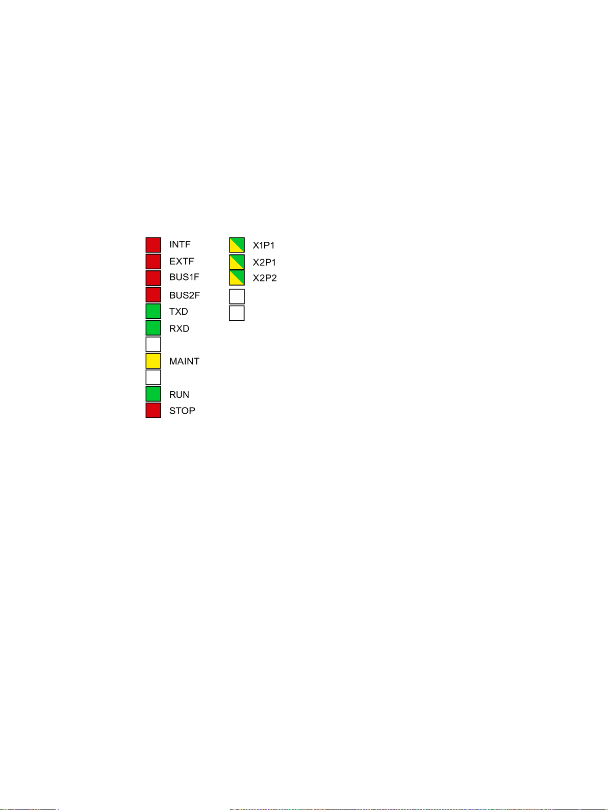
The display on the front panel consists of the following LEDs that indicate the operating
mode and communications status.
Figure 4-1 LEDs front panel CP 443-1 Advanced
The LEDs have the following meaning:
● INTF: Internal error
● EXTF: External error
● BUS1F: Bus fault on Ethernet interface
● BUS2F: Bus fault RNA interface
● TXD: Frame traffic (sending) over Ethernet
● RXD: Frame traffic (receiving) over Ethernet
● MAINT: Maintenance necessary (diagnostics buffer)
● RUN: RUN mode
● STOP: STOP mode
● X1 P1: Link status / activity of the Ethernet port of the Ethernet interface
● X2P1, X2P2: Link status / activity of Ethernet port 1, 2 of the RNA interface
CP 443-1 RNA
Manual, 03/2019, C79000-G8976-C299-04
27
Page 28
LEDs
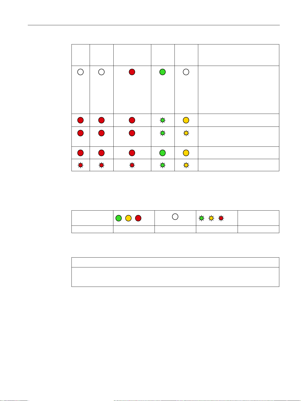
INTF
(red)
EXTF
(red)
BUSF
(red) BUS1F /
BUS2F (red) *)
RUN
(green)
STOP
(yellow)
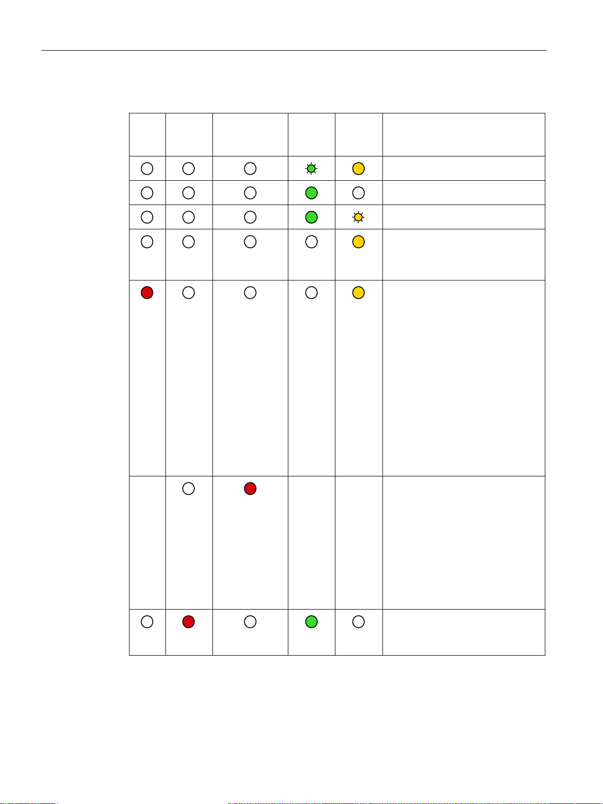
CP operating mode
possible.
vides detailed information.
Unlabeled LEDs have no significance (only relevant for diagnostics).
Starting up (STOP->RUN)
Running (RUN)
Stopping (RUN->STOP)
-
- -
Stopped (STOP)
In STOP mode, configuring and per-
forming diagnostics on the CP remain
• STOP with internal error
(for example IP double addressing
detected during startup of the CP
in network)
or
• following memory reset / reset to
factory defaults
The following applies in this status:
• The CPU or intelligent modules in
the rack remain accessible using
PG functions (over MPI or the ISO
protocol).
• SNMP functionality and access
using HTTP are not possible.
• Error on the RNA interface
(BUS2F)
– The transmission mode of the
communications partner is not
permitted (only the "automatic
setting" mode with 100 Mbps
full duplex)
– PRP error
or
• double IP address
CP 443-1 RNA
28 Manual, 03/2019, C79000-G8976-C299-04
• RUN with external error;
The CP diagnostics buffer pro-
Page 29
LEDs
INTF
(red)
EXTF
(red)
BUSF
(red) BUS1F /
BUS2F (red) *)
RUN
(green)
STOP
(yellow)
CP operating mode
nately)
*)
umn.
Symbol
Meaning
ON
OFF
Flashing
any
The "MAINT" LED (yellow)
NOTICE
• A duplicate IP address was de-
tected after the CP was in RUN.
or
• Difference in the transmission
medium or the duplex settings between the configuration and the
actual system
Loading using the Firmware Loader is
active.
The firmware download was aborted.
(STOP LED and RUN LED flash alter-
Firmware is being activated.
Module fault / system error
The behavior applies to BUS1F and BUS2F if there is no restriction listed in the "CP mode" col-
Table 4- 1 Legend
-
CP 443-1 RNA
Manual, 03/2019, C79000-G8976-C299-04
As long as the "MAINT" LED is lit, there is an internal update taking place on the CP.
Check the entries in the diagnostics buffer of the device.
29
Page 30
LEDs
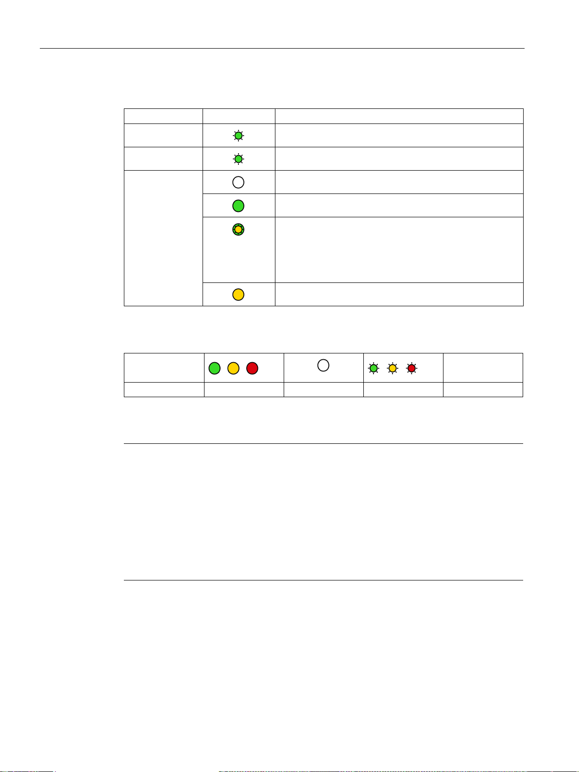
CP communications status / LED display patterns
LED
Display
Meaning
each port.
Symbol
Meaning
Module identification
Note
Module identification - make the port LEDs flash briefly
With the help of Web diagnostics or the online functions of STEP 7, you can search for and
identify the module in the rack. The options
•
•
When t
See also
TXD (green)
RXD (green)
X1P1
X2P1 / X2P2
(green / yellow)
Table 4- 2 Legend
ON OFF Flashing any
CP sending over Ethernet.
CP is receiving over Ethernet.
Port has no connection over Ethernet.
Existing connection over port to Ethernet (LINK status).
LED flashes yellow (constant light green):
Port is sending / receiving via Ethernet.
Note:
Here, all received / sent frames are signaled separately for
There is permanent data transfer via Ethernet at the port.
-
for this are as follows:
In Web diagnostics
You click the "Flash" button in the update center.
In STEP 7
You click the "Flash" button in the "Browse network" dialog
he "Flash" button is clicked, the port LED of the enabled interface flashes briefly.
Loading new firmware (Page 51)
CP 443-1 RNA
30 Manual, 03/2019, C79000-G8976-C299-04
Page 31
5
5.1
Important notes on using the device
Safety notices on the use of the device
WARNING
Safety requirements for installation
5.1.1
Notices on use in hazardous areas
WARNING
WARNING
EXPLOSION HAZARD
Note the following safety notices when setting up and operating the device and during all
associated work such as installation, connecting up or replacing the device.
The devices are "open equipment" according to the standard IEC 61010-2-201or UL 508 /
CSA C22.2 No. 142. To fulfill requirements for safe operation with regard to mechanical
stability, flame retardation, stability, and protection against contact, the following alternative
types of installation are specified:
• Installation in a suitable cabinet.
• Installation in a suitable enclosure.
• Installation in a suitably equipped, enclosed control room.
The device may only be operated in an environment with pollution degree 1 or 2 (see IEC
60664-1).
The device must not be opened.
CP 443-1 RNA
Manual, 03/2019, C79000-G8976-C299-04
31
Page 32
Installation, connecting up, commissioning
WARNING
Power supply
WARNING
EXPLOSION HAZARD
WARNING
EXPLOSION HAZARD
WARNING
5.1.2
Notices on use in hazardous areas according to ATEX / IECEx
WARNING
Requirements for the cabinet
5.1 Important notes on using the device
The equipment is designed for operation with Safety Extra-Low Voltage (SELV) by a
Limited Power Source (LPS).
This means that only SELV / LPS complying with IEC 60950-1 / EN 60950-1 / VDE 0805-1
must be connected to the power supply terminals. The power supply unit for the equipment
power supply must comply with NEC Class 2, as described by the National Electrical Code
(r) (ANSI / NFPA 70).
DO NOT CONNECT OR DISCONNECT EQUIPMENT WHEN A FLAMMABLE OR
COMBUSTIBLE ATMOSPHERE IS PRESENT.
SUBSTITUTION OF COMPONENTS MAY IMPAIR SUITABILITY FOR CLASS I, DIVISION
2 OR ZONE 2.
When used in hazardous environments corresponding to Class I, Division 2 or Class I,
Zone 2, the device must be installed in a cabinet or a suitable enclosure.
To comply with EC Directive 94/9 (ATEX95) or the conditions of IECEx, this enclosure or
cabinet must meet the requirements of at least IP54 in compliance with EN 60529.
CP 443-1 RNA
32 Manual, 03/2019, C79000-G8976-C299-04
Page 33
Installation, connecting up, commissioning
WARNING
Cable
WARNING
5.1.3
Notices on use in hazardous areas according to UL HazLoc
WARNING
EXPLOSION HAZARD
5.2
Installation - procedure
5.2 Installation - procedure
If the cable or conduit entry point exceeds 70 °C or the branching point of conductors
exceeds 80 °C, special precautions must be taken. If the equipment is operated in an air
ambient in excess of 50 °C, only use cables with admitted maximum operating temperature
of at least 80 °C.
Take measures to prevent transient voltage surges of more than 40% of the rated voltage.
This is the case if you only operate devices with SELV (safety extra-low voltage).
DO NOT DISCONNECT WHILE CIRCUIT IS LIVE UNLESS AREA IS KNOWN TO BE
NON-HAZARDOUS.
This equipment is suitable for use in Class I, Division 2, Groups A, B, C and D or nonhazardous locations only.
This equipment is suitable for use in Class I, Zone 2, Group IIC or non-hazardous locations
only.
The steps for installing the CP are explained below.
Result: The CP is installed in the rack and the interfaces have been networked.
CP 443-1 RNA
Manual, 03/2019, C79000-G8976-C299-04
33
Page 34

Installation, connecting up, commissioning
Follow the steps outlined below:
Note
K bus link
When using the universal rack UR1 or UR2 as an expansion rack, a communication bus
link is necessary!
See also
5.3
Commissioning - procedure
5.3 Commissioning - procedure
1. Plugging in the CP:
Fit the CP onto the rack from the top and push it in at the bottom.
The CP can be operated in central or universal racks.
2. Secure the CP with screws.
3. Turn on the power supply.
4. Connect the CP to Industrial Ethernet via one of the RJ45 jacks.
Network settings (Page 42)
The steps for commissioning the CP are explained below. Commissioning involves the
addressing and downloading the configuration data and user programs.
Result: The CP is reachable in the network and has been supplied with configuration data.
CP 443-1 RNA
34 Manual, 03/2019, C79000-G8976-C299-04
Page 35

Installation, connecting up, commissioning
Follow the steps outlined below:
Note
You can connect the PG when configuring the CP as follows:
•
•
The PG/PC requires a LAN attachment, for example via a CP 1623 or CP 1411 and
must have the
IE). The TCP/IP protocol or ISO protocol must be installed. The protocol used must
then be applied to the S7ONLINE access point.
5.4
Replacing a module without a programming device
General procedure
Note
Configured MAC address is adopted
When setting the ISO protocol, remember that MAC address set previously during
configuration is transferred by the CPU to the new CP module.
5.4 Replacing a module without a programming device
1. Download the configuration data from your STEP 7 project to the S7400 station.
– Requirement:
You have configured the CP in a STEP 7 project for the properties and services you
want to use.
via MPI
via Industrial Ethernet
For further details, refer to the general part /1/ (Page 67) of this manual:
– Initial addressing (node initialization);
– Downloading the configuration
necessary software (for example the S71623 package or SOFTNET
2. Use the diagnostics functions during commissioning and to analyze problems.
You have the following options available:
– Hardware diagnostics and troubleshooting with STEP 7.
– Communication diagnostics with special diagnostics.
– Web diagnostics.
The configuration data of the CP is stored on the CPU. This makes it possible to replace this
module with a module of the same type (identical order number) without a PG.
For information on replacement using other modules, refer to the information in section
Replacing the modules used with CP 443-1 RNA (Page 52).
CP 443-1 RNA
Manual, 03/2019, C79000-G8976-C299-04
35
Page 36

Installation, connecting up, commissioning
5.5
Controlling the mode
Change from STOP to RUN:
Change from RUN to STOP:
5.5 Controlling the mode
You can change the mode of the CP between RUN and STOP using the STEP 7
configuration software or using STEP 7 special diagnostics.
The CP loads configured and/or downloaded data into the work memory and then changes
to RUN mode.
The CP changes to STOP (transitional phase with LED display "Stopping").
The reaction is as follows in STOP:
● Established connections (ISO transport, ISOonTCP, TCP, UDP connections) are
terminated
● The following the functions are disabled:
– Time-of-day synchronization
● The following functions remain enabled:
– The configuration and diagnostics of the CP (system connections for configuration,
diagnostics, and PG channel routing are retained);
– Web diagnostics
CP 443-1 RNA
36 Manual, 03/2019, C79000-G8976-C299-04
Page 37

6
6.1
Security recommendations
General
Physical access
Network attachment
Keep to the following security recommendations to prevent unauthorized access to the
system.
● You should make regular checks to make sure that the device meets these
recommendations and other internal security guidelines if applicable.
● Evaluate your plant as a whole in terms of security. Use a cell protection concept with
suitable products.
● Do not connect the device directly to the Internet. Operate the device within a protected
network area.
● Keep the firmware up to date. Check regularly for security updates of the firmware and
● Check regularly for new features on the Siemens Internet pages.
Restrict physical access to the device to qualified personnel.
Do not connect the PC directly to the Internet. If a connection from the CP to the Internet is
required, arrange for suitable protection before the CP, for example a SCALANCE S with
firewall.
use them.
– Here you will find information on industrial security:
Link: (http://www.siemens.com/industrialsecurity)
– Here you will find information on security industrial communication:
Link: (http://w3.siemens.com/mcms/industrial-communication/en/ie/industrial-ethernet-
security/Seiten/industrial-security.aspx)
– You can find a publication on the topic of network security (6ZB5530-1AP0x-0BAx)
here:
Link:
(http://w3app.siemens.com/mcms/infocenter/content/en/Pages/order_form.aspx?node
Key=key_518693&infotype=brochures)
Enter the following filter: 6ZB5530
CP 443-1 RNA
Manual, 03/2019, C79000-G8976-C299-04
37
Page 38

Configuration and operation
Security functions of the product
Know-how protection of blocks (STEP 7 V5)
Passwords
6.1 Security recommendations
Use the options for security settings in the configuration of the product. These includes
among others:
● Protection levels
– Configure a protection level of the CPU.
– Configure the protection level "Status-dependent".
● Security function of the communication
– Enable the IP access protection of the CP (HW Config).
– Disable access to the Web server of the CPU (CPU configuration) and on the CP.
● Protection of the passwords of program blocks
Protect the passwords stored in data blocks for the blocks from being viewed. The
procedure is described below.
You can prevent the contents of data blocks (e.g. passwords) being read out by protecting
the block with the "KNOW_HOW_PROTECT" option. Follow the steps outlined below in
STEP 7:
1. Select the DB in the block folder.
2. Open the block in the editor.
3. Close the block in the editor.
4. Generate a source from the block in the editor.
5. Select the source of the DB in the sources folder.
6. Open the source.
7. Insert an empty line in the header of the source and write "KNOW_HOW_PROTECT" in
this line.
8. Compile the source.
Result: The block is protected. You can recognize this by the padlock symbol in the block
folder.
If you want to later change parameters in a DB, for example a password, remember the
following: The contents of a DB with know-how protection are no longer visible and can only
be changed via the source or by direct assignment of parameters.
● Define rules for the use of devices and assignment of passwords.
● Regularly update the passwords to increase security.
● Only use passwords with a high password strength. Avoid weak passwords for example
"password1", "123456789" or similar.
CP 443-1 RNA
38 Manual, 03/2019, C79000-G8976-C299-04
Page 39

Configuration and operation
Protocols
Secure and non-secure protocols
Table: Meaning of the column titles and entries
Protocol / function
Port number (protocol)
Default of the port
Port status
Authentication
Protocol / function
Port number (protocol)
Default of the port
Port status
Authentication
HTTP
80 (TCP)
Open
Open after configuration
No
ISO-on-TCP
(RFC1006)
NTP
123 (UDP)
Closed
Open after configuration
No
SNMP
6.1 Security recommendations
● Make sure that all passwords are protected and inaccessible to unauthorized personnel.
See also the preceding section for information on this.
● Do not use one password for different users and systems.
● Only activate protocols that you require to use the system.
The following table provides you with an overview of the open ports on this device.
●
Protocols that the device supports.
●
Port number assigned to the protocol.
●
– Open
The port is open at the start of the configuration.
– Closed
The port is closed at the start of the configuration.
●
– Open
The port is always open and cannot be closed.
– Open according to configuration
The port is open if it has been configured.
– Open (login, when configured)
As default the port is open. After configuring the port, the communications partner
needs to log in.
●
Specifies whether or not the protocol authenticates the communications partner during
access.
161 (UDP) Open Open after configuration Yes (with SNMPv3)
CP 443-1 RNA
Manual, 03/2019, C79000-G8976-C299-04
102 (TCP) Open Open No
39
Page 40

Configuration and operation
6.2
Switching over interfaces
NOTICE
Interface change - load configuration data only via other module
6.3
Memory reset / reset to factory defaults
Note
Data on the CP is deleted - CPU data is retained
The functi
the configuration data on the CPU! Only the data kept on the CP is deleted.
If you subsequently upload the configuration data from the CPU to a PG you will always
object the c
connections, IP address).
Note
Memory reset - ACL (access control list)
After a memory reset on the module, the following applies:
•
6.2 Switching over interfaces
The choice of the interface to be used, RNA interface or Ethernet interface is made in the
configuration of the CP. Each configuration or changeover of the interface therefore requires
that the configuration data is downloaded again.
If you change over the currently active interface and when you load the configuration data,
you will need to use an interface of the CPU or the interface of another CP to load the
configuration data.
If you load the configuration data via the interface of the CP 443-1 RNA, on which the
interface should be switched over, the loading cannot be completed.
The CP has a twolevel function available for resetting memory:
● Memory reset
● Resetting to factory setting
ons for resetting and resetting to factory defaults described here do not change
onfiguration data that was previously on the CP (with parameters,
ACL remains active.
CP 443-1 RNA
40 Manual, 03/2019, C79000-G8976-C299-04
Page 41

Configuration and operation
How to use the functions
Clear/reset module - effects
Reset to factory defaults - effects
6.3 Memory reset / reset to factory defaults
You can start the memory reset functions in STEP 7. The CP must be in STOP. When you
reset memory using special diagnostics, the CP is automatically changed to STOP.
● Memory reset
– In STEP 7 V5.5 with the menu command "PLC" > "Clear/Reset"
– In STEP 7 special diagnostics with the "Operating Mode" > "Clear/Reset Module"
menu command
● Resetting to factory settings
– In STEP 7 V5.5 with the menu command "PLC" > "Edit Ethernet Node..." > Select CP
> "OK" > "Reset to Factory Defaults"
– In STEP 7 special diagnostics with the "Operating Mode" > "Reset to Factory Settings"
menu command
Following the memory reset, the CP retains the configured MAC address, the IP address and
the retentive parameters. The CP is therefore immediately ready for downloads using the IP
address.
The configuration data is retained on the CPU.
The CPU in the S7 station does not recognize that the CP memory was reset. The CP
changes to the "Stopped (STOP) with error" state (see LEDs (Page 27)). The configuration
data must then be reloaded. You can also initiate this loading by cycling power (OFF/ON).
After resetting to factory defaults, the CP always retains the factory set MAC address (as
supplied).
The IP address and the configuration data in the CP RAM are deleted. The configuration
data is retained on the CPU.
CP 443-1 RNA
Manual, 03/2019, C79000-G8976-C299-04
41
Page 42

Configuration and operation
6.4
Network settings
6.4.1
Reserved MAC address
NOTICE
Do not use the MAC address
6.4.2
Transmission properties of the Ethernet and RNA interfaces
Automatic setting or individual network settings
Note
In normal situations, the basic setting ensures trouble
change this in exceptional situations.
Autocrossing mechanism
6.4 Network settings
Internally, the CP uses the following reserved MAC address:
00-1B-1B-31-4D-00
Do not use this MAC address for communications partners of the CP, otherwise no
communication is possible with the communications partner.
The common transmission characteristics of the two interfaces are described below.
The configuration of the network settings "Transmission medium / duplex" is made for the
Ethernet interfaces in the properties of the port in STEP 7/HW Config:
Row "X1P1": Port properties of the Ethernet interface
As default, the CP is configured for automatic detection (autosensing) for both interfaces.
The settings for the RNA interface are fixed.
If necessary, you can change the settings for the Ethernet interface.
Ethernet interface:
If you create a manual configuration for the CP and disable the autonegotiation option, the
automatic negotiation of the network settings (autonegotiation) is no longer effective. If, on
the other hand, the communications partner works with autonegotiation, it is not certain that
error-free communication will be established.
free communication. You should only
With the integrated autocrossing mechanism, it is possible to use a standard cable to
connect the PC/PG. A crossover cable is not necessary.
CP 443-1 RNA
42 Manual, 03/2019, C79000-G8976-C299-04
Page 43

Configuration and operation
STEP 7 special diagnostics and Web diagnostics display the network setting
Further notes:
6.4 Network settings
Diagnostics of the port settings for the CP described here is possible using the entries in the
diagnostics buffer using SNMP, special diagnostics, and the LED displays.
You will find information on the currently used network settings in STEP 7 as follows:
● in special diagnostics under the diagnostics object "Industrial Ethernet" in the "Network
Attachment" group box;
● in STEP 7 with the menu command "PLC > Module Information";
● In Web diagnostics.
● 10/100 Mbps network components without "autonegotiation"
If you use 10/100 Mbps network components that do not support "Autonegotiation", it is
possible that you will have to set the mode manually.
● Forcing a specific mode instead of "Automatic settings"
If your application requires a specific mode instead of the automatic settings, you will
need to match up the partner devices.
● No reaction to Autonegotiation query with manual configuration
Remember that if you configure the CP manually and the "Autonegotiation" option is
disabled, it will not react to an autonegotiation query! As a result, a connected partner
may not be able to set the required mode and communication will not be ideal.
Example:
If, for example, the CP is set to "100 Mbps - full duplex" and autonegotiation is disabled, a
CP connected as partner will set "100 Mbps - half duplex". Reason: Due to the fixed
setting, an autonegotiation reply is not possible. Although the connected partner detects
100 Mbps with autosensing, it remains at half duplex.
● Recommendation: Change individual network settings only over MPI
If you modify the LAN settings, these changes will be adopted by the CP and activated
when the configuration data is downloaded to the target system (STEP 7). In some
situations, the device may then no longer be obtainable over Ethernet.
We therefore recommend that you download configuration data to the S7 station over an
MPI connection if you change this setting.
If you download the configuration data via the LAN interface then, depending on the
selected setting, it is possible that the current download will not be completed due to the
changes to the configuration taking immediate effect and an inconsistent configuration is
reported.
Example:
The download is started initially with the setting TP/ITP at 10 Mbps half duplex. If the
"Individual network settings" are now changed to 100 Mbps full duplex, the download
cannot be completed.
CP 443-1 RNA
Manual, 03/2019, C79000-G8976-C299-04
43
Page 44

Configuration and operation
6.5
IP configuration
6.5.1
Setting the IP address
6.5.2
Detecting duplicate IP addressing in the network
Behavior during operation (CP in RUN)
Behavior when the CP starts up
6.5 IP configuration
You can only assign the CP an IP address in the factory settings status.
To be able to assign an already configured CP a new IP address using PST or the STEP 7
function "Edit Ethernet node", you will need to reset this to its factory settings.
To save you timeconsuming troubleshooting in the network, the CP detects double
addressing in the network.
If the CP detects double addressing on the network (new node with an IP address that has
already been assigned), a message is generated in the diagnostics buffer and the bus fault
LED lights up.
The CP remains in RUN mode. After the device with the duplicate IP address has been
removed from the network, the bus fault LED goes off automatically.
If duplicate addressing is detected when the CP starts up, the CP remains in STOP. The bus
fault LED is lit and a diagnostics buffer entry is generated.
Restart the CP after the double addressing problem has been eliminated.
CP 443-1 RNA
44 Manual, 03/2019, C79000-G8976-C299-04
Page 45

Configuration and operation
6.6
Time-of-day synchronization
General rules
Note
No automatic changeover to daylight saving is defined in NTP. As a result, you may need
to implement this changeover using a program application.
Note
Note the following about time
If an NTP frame is detected by the
synchronized externally), there is no forwarding on the K bus. If this problem occurs,
none of the NTP servers is displayed as "NTP master" in the diagnostics; rather all NTP
servers are displayed only as bein
Project engineering
6.7
Recommendation for use with a high communications load
Reason
Known problems
6.6 Time-of-day synchronization
On the RNA interface, the CP supports the following two modes for timeofday
synchronization:
● SIMATIC mode
● NTP mode (NTP: Network Time Protocol)
ofday synchronization in NTP mode:
CP as "not exact" (example: NTP server is not
For more detailed information on configuration, refer to the online help of the "Time-of-day
synchronization" parameter group and in Part A of the manual /1/ (Page 67).
To avoid an overload situation on the CPU you are using, note the following information
about the CP.
● The program blocks for sending and receiving AG_SEND / AG_RECV (FC5/FC6,
g accessible.
FC50/60 or FC53/63) are often called cyclically in OB1. This leads to constant
communication between the CPU and CP. As a result, other types of communication
such as PG functions cannot be executed or only very slowly.
● HMI systems access data of the CPU too often using S7 functions. This slows down
communication overall and there may be resource bottlenecks on the CPU.
CP 443-1 RNA
Manual, 03/2019, C79000-G8976-C299-04
45
Page 46

Configuration and operation
Remedy
6.8
SNMP agent
SNMP (Simple Network Management Protocol)
MIB file and SNMP profile file
Further information
6.8 SNMP agent
Note the following recommendations:
● Do not call communication program blocks cyclically in OB1!
Instead, call up communication time-controlled in a suitable time OB. The call interval of
this OB should be significantly higher than the average cycle time of OB1.
● Set a minimum cycle time that is higher than the average execution time of OB1. This
frees resources for communication on the CPU. Setting a minimum cycle time is a
suitable solution, for example, for existing applications when communication already
takes place cyclically in OB1.
● If necessary, reduce the time for processing communication on the CPU. The setting is
made with the "Cycle load due to communication" parameter in the properties of the CPU.
SNMP is a protocol for managing networks. To transmit data, SNMP uses the
connectionless UDP protocol.
The information on the properties of SNMPcompliant devices is entered in MIB files (MIB =
Management Information Base).
The CP supports data queries using SNMP in version 1. It supplies the content of certain
MIB objects according to MIB-II (RFC1213), PRP-MIB IEC62439 (IEC-62439-3-MIB) and
Automation System MIB.
You will find the MIB file and the SNMP profile file of the module in the STEP 7 installation in
the folders "S7DATA" > "snmp" under the name of the module.
For more detailed information on working with MIB files, refer to the documentation of the
SNMP client you are using (example of an SNMP client: SNMP OPC server from
SIMATIC NET).
You will find more information on the MIB on the Internet:
Link: (https://support.industry.siemens.com/cs/ww/en/view/15177711)
CP 443-1 RNA
46 Manual, 03/2019, C79000-G8976-C299-04
Page 47

Configuration and operation
Supported MIBs
"Interfaces" MIB group
ifIndex
Type of interface
1
Ethernet interface
6.8 SNMP agent
The CP supports the following groups of MIB objects of the standard MIB II according to
RFC1213:
● System
● Interfaces
● IP
● ICMP
● TCP
● UDP
● SNMP
The other groups of the MIB II standard are not supported:
● EGP
● Transmission
● at
The CP also supports the Automation System MIB and the PRP-MIB (IEC-62439-3-MIB).
Exceptions / restrictions:
● Write access is permitted only for the following MIB objects of the system group:
– sysContact
– sysLocation
– sysName
For all other MIB objects / MIB object groups, only read access is possible for security
reasons.
● Traps are not supported by the CP.
The "Interfaces" MIB object provides status information about the CP interfaces. The MIB
objects of the ifTable provide the status information of the interfaces. The "ifIndex" object
identifier is assigned to the CP interfaces as follows:
Table 6- 1 ifIndex
2-3 Port 1-2 (RNA interface)
CP 443-1 RNA
Manual, 03/2019, C79000-G8976-C299-04
47
Page 48

Configuration and operation
Access permissions using community name
Type of access
Community name *)
Read access
public
*) Note the use of lowercase letters!
MIB files for your SNMP tools
6.9
Interface in the user program
6.9.1
Call interface for open communications services SEND/RECV
Change call parameters only after job confirmation
Note
Note the following for the call interface of the program blocks AG_SEND / AG_LSEND /
AG_SSEND or AG_RECV / AG_LRECV / AG_SRECV:
Once the job has been triggered, you can only make changes again after the program block
has confirmed completion of the job with DONE=1 or with ERROR=1.
If this is ignored, it is possible that the execution of the job w
resources could be permanently occupied on the CPU.
6.9 Interface in the user program
The CP uses the following community names to control the access rights in the SNMP
agent:
Table 6- 2 Access rights in the SNMP agent
Read and write access private
If you use an SNMP tool, you will find the MIB files relevant to the CP in the STEP 7
installation in the following folder:
<Drive>\<Installation folder>\Siemens\Step7\S7DATA\snmp\mib
There, you will find, for example, the following MIB files:
● automationPS.mib
● automationSmi.mib
● automationSystem.mib
● automationTC.mib
● IEC-62439-3-MIB.mib
ill be aborted with an error and
CP 443-1 RNA
48 Manual, 03/2019, C79000-G8976-C299-04
Page 49

Configuration and operation
6.9.2
Open TCP/IP communication
Note
Validity
The information in this section applies only to the RNA interface.
Use
Programming
Note
Note that the number of dynamically established connections also depends on the number of
configured, statically established connections.
You will receive corresponding
6.9 Interface in the user program
To allow the user program to exchange data with other TCP/IPcompliant communications
partners, STEP 7 provides a UDT for the connection parameter assignment and four
program blocks:
● UDT 65 "TCON_PAR" with the data structure for connection parameter assignment
● FB65 "TCON" for connection establishment
● FB66 "TDISCON" for connection termination
● FB63 "TSEND" for sending data
● FB64 "TRCV" for receiving data
TCP/IP communication is connectionoriented. Data can be transmitted only when a
connection has been established to the communications partner. The CPU can use several
connections to a communications partner at the same time.
The following protocol variants are supported:
● ISO on TCP according to RFC 1006
Make the following parameter settings in the connection description (UDT 65):
● local_tsap_id: Byte 1 = 0xE0 (value mandatory for correct functionality)
● local_tsap_id: Byte 2 = rack/slot number
● remote_tsap_id: Byte 1 = 0xE0 (value mandatory for correct functionality)
● remote_tsap_id: Byte 2 = rack/slot number
Note: The TSAPs can be 2-16 bytes long. The first two bytes must be occupied as
described, you can use the other bytes to suit your task.
condition codes on the call interface of the FBs.
Refer to the documentation of the program blocks in the online help and in the
documentation for STEP 7. There, you will also find examples of parameter assignment!
CP 443-1 RNA
Manual, 03/2019, C79000-G8976-C299-04
49
Page 50

Configuration and operation
6.10
Ping: Permitted length of ICMP packets
6.11
Communication in PRP mode
6.10 Ping: Permitted length of ICMP packets
Pings with a packet size of more than 1000 bytes are evaluated as an attack and filtered by
the CP. This response is intentional and improves the robustness of the CP in an industrial
environment.
A ping simply serves to check reachability. There is therefore no need to support extremely
long ICMP packets.
In PRP mode, the first frame from an unknown node is discarded and remains unanswered.
This response must be taken into account with the services that do not generally cause any
frame repetitions such as:
● Firmware download (see also section Loading new firmware (Page 51))
● Searching the network
● PING
CP 443-1 RNA
50 Manual, 03/2019, C79000-G8976-C299-04
Page 51

7
7.1
Loading new firmware
Options for a firmware update
How to download new firmware
The following alternative methods can be used to download new firmware to a SIMATIC NET
CP:
● Using the firmware loader supplied with STEP 7
Requirement for downloading:
– To download firmware, you require an Industrial Ethernet CP module in the PG/PC
(for example, CP 1613) or a normal Ethernet module with the "Softnet" software
package.
– The S7ONLINE interface must be set to the "ISO - Industrial Ethernet" protocol. It is
not possible to download using TCP/IP (and therefore not to other networks).
Always run the download using the active MAC address of the CP!
● Using the update center
You can reach the update center using Web diagnostics.
The CP supports the storage of several firmware versions. Using the firmware load
function in the update center, you can activate the required firmware version.
Requirement: The "Firmware download via Web" option is selected in the configuration
and the user rights have been set.
Note the descriptions of firmware downloads in the manual Part A /1/ (Page 67).
You can download the firmware via the active interface of the CP.
Follow the steps outlined below:
1. Connect the CP module to the PG/PC via a LAN cable.
2. Start the download on your PG/PC using one of the firmware download functions
described above.
The download involves two stages:
– Section 1: Downloading firmware
– Section 2: Activating firmware
You will find the LED displays in the section LEDs (Page 27)
If the download is aborted, RUN and STOP flash alternately.
3. After the firmware download, the CP goes through a warm restart.
CP 443-1 RNA
Manual, 03/2019, C79000-G8976-C299-04
51
Page 52

Upkeep and maintenance
NOTICE
Behavior in PRP mode
What to do if a download is interrupted
Note
PRP mode
A timeout may be indicated in PRP mode. In this case, restart the firmware download again.
7.2
Replacing the modules used with CP 443-1 RNA
Converting
Replacement of a CP 443-1 (EX20 / EX30)
7.2 Replacing the modules used with CP 443-1 RNA
If you start the download, this can lead to a timeout being indicated in PRP mode. In this
case, restart the download. You should also refer to the explanation in the section
Communication in PRP mode (Page 50)
Disturbances or collisions on the network can lead to packets being lost. In such cases, this
can lead to an interruption of the firmware download. The firmware loader then signals a
timeout or negative response from the module being loaded. En entry is made in the
diagnostics buffer. The CP restarts with the firmware that existed before the aborted
download.
Repeat the download using the active MAC address after the CP has started up again.
If you cannot start the download again following an aborted attempt, you should turn off the
entire rack and turn it on again. You can then restart the firmware download.
By adhering to certain rules and restrictions, you can replace other module types with the CP
443-1 RNA.
When replacing modules, the following module types can be considered:
● CP 443-1 EX20 / EX30
Taking into account the following information, the range of functions of the replaced module
will continue to be supported with the specified restrictions.
Note the following procedure when replacing modules:
CP 443-1 RNA
52 Manual, 03/2019, C79000-G8976-C299-04
Page 53

Upkeep and maintenance
Adapting the configuration
Effects
7.2 Replacing the modules used with CP 443-1 RNA
1. In the STEP 7 configuration, replace the already configured CP with the new module; You
will find this in the hardware catalog.
2. As soon as you drag the new module from the catalog onto the module you are replacing,
the configured connections and data are adopted.
3. If necessary, modify the configuration according to your requirements, for example in the
Properties dialog for the Ethernet subnet.
4. Save and compile the project.
5. Download the configuration data to the target system again.
The CP 443-1 RNA adopts the settings of the EX20/EX30 as far as it supports them.
After the replacement, the CP is in the mode with the activated RNA interface with port 1 as
the only port in use (no PRP mode)
The following continues to apply:
● Functions, such as DHCP are not supported.
● The previously set IP parameters are adopted.
● If the replaced CP was configured as a PROFINET IO controller, the PROFINET line will
be detached from the module. The PROFINET line can then be assigned to another
PROFINET IO controller in STEP 7.
● Connections are assigned to the RNA interface.
● Explicit parameter assignments of the ports are lost since the CP 443-1 RNA does not
support this.
CP 443-1 RNA
Manual, 03/2019, C79000-G8976-C299-04
53
Page 54

Upkeep and maintenance
7.2 Replacing the modules used with CP 443-1 RNA
CP 443-1 RNA
54 Manual, 03/2019, C79000-G8976-C299-04
Page 55

8
Technical specifications
Attachment to Industrial Ethernet
1 x RNA interface with 2 ports
Connector
1 x RJ-45 jacks
Transmission speed
10 / 100 Mbps half duplex or full duplex
Connector
2 x RJ-45 jacks
Transmission speed
100 Mbps full duplex
Electrical data
Power supply
via S7 backplane bus
5 V
From backplane bus
2 A
Power dissipation
10 W
Permitted ambient conditions
During operation
0 °C to +60 °C
During storage
-40 °C to +70 °C
During transportation
-40 °C to +70 °C
Relative humidity
During operation
≤ 95 % at 25 °C, no condensation
Operating altitude
≤ 2,000 m above sea level
Contaminant concentration
Acc. to ISA-S71.04 severity level G1, G2, G3
Design, dimensions and weight
Degree of protection
IP20
Weight
Approx. 700 g
Dimensions (W x H x D)
25 x 290 x 210 mm
Installation options
Mounting in an S7-400 rack
Permitted cable lengths
(Alternative combinations per length range) *
Number 1 x Ethernet interface
Design of the Ethernet interface
Design of the RNA interface
Current consumption
Ambient temperature
Module format Compact module for S7-400, single width
0 ... 55 m
0 ... 85 m
• Max. 55 m IE TP Torsion Cable with IE FC RJ45 Plug 180
• Max. 45 m IE TP Torsion Cable with IE FC RJ45 + 10 m TP Cord via
IE FC RJ45 Outlet
• Max. 85 m IE FC TP Marine/Trailing/Flexible/FRNC/Festoon/Food Cable with
IE FC RJ45 Plug 180
• Max. 75 m IE FC TP Marine/Trailing/Flexible/FRNC/Festoon/Food Cable +
10 m TP Cord via IE FC RJ45 Outlet
CP 443-1 RNA
Manual, 03/2019, C79000-G8976-C299-04
55
Page 56

Technical specifications
Technical specifications
Product functions **
0 ... 100 m
• Max. 100 m IE FC TP Standard Cable with IE FC RJ45 Plug 180
• Max. 90 m IE FC TP Standard Cable + 10 m TP Cord via IE FC RJ45 Outlet
* For details, refer to the IK PI catalog, cabling technology
** You will find the product functions in the section Application and functions (Page 9).
For further data, refer to section Performance data (Page 17)
In addition to this, all the information in the S7-400/M7-400 reference manual "Module Data"
/10/ (Page 70) in the section "General Technical Specifications" on the topics listed below
applies to the CP
● Electromagnetic compatibility
● Transportation/storage conditions
● Mechanical and climatic environmental conditions
● Information on insulation checks, protection class and degree of protection
CP 443-1 RNA
56 Manual, 03/2019, C79000-G8976-C299-04
Page 57

9
Approvals issued
Note
Issued approvals on the type plate of the device
The specified approvals apply only when the corresponding mark is printed on the product.
You can check which
markings on the type plate.
Approvals for shipbuilding are not printed on the device type plate.
EC declaration of conformity
94/9/EC (ATEX explosion protection directive, up to 19.04.2016)
2014/34/EU (ATEX explosion protection directive, as of 20/04/2016)
2004/108/EC (EMC up to 19.04.2016)
2014/30/EU (EMC, as of 20/04/2016)
2011/65/EU (RoHS)
of the following approvals have been granted for your product by the
The CP meets the requirements and safety objectives of the following EU directives and it
complies with the harmonized European standards (EN) for programmable logic controllers
which are published in the official documentation of the European Union.
●
Directive of the European Parliament and the Council of March 23, 1994 on the
approximation of the laws of the Member States concerning equipment and protective
systems intended for use in potentially explosive atmospheres
●
Directive of the European Parliament and the Council of 26 Febrary 2014 on the
approximation of the laws of the Member States concerning equipment and protective
systems intended for use in potentially explosive atmospheres, official journal of the EU
L96, 29/03/2014, pages. 309-356
●
Directive of the European Parliament and of the Council of December 15, 2004 on the
approximation of the laws of the member states relating to electromagnetic compatibility.
●
EMC directive of the European Parliament and of the Council of February 26, 2014 on the
approximation of the laws of the member states relating to electromagnetic compatibility.;
official journal of the EU L96, 29/03/2014, pages. 79-106
●
Directive of the European Parliament and of the Council of 8 June 2011 on the restriction
of the use of certain hazardous substances in electrical and electronic equipment
The EC Declaration of Conformity is available for all responsible authorities at:
CP 443-1 RNA
Manual, 03/2019, C79000-G8976-C299-04
57
Page 58

Approvals
IECEx
ATEX
Siemens Aktiengesellschaft
Division Process Industries and Drives
Process Automation
DE-76181 Karlsruhe
Germany
You will find the EC Declaration of Conformity on the Internet at the following address:
Link: (https://support.industry.siemens.com/cs/ww/en/ps/15353/cert)
> Entry type: "Certificates", certificate type: "EC Declaration of Conformity"
The product meets the requirements of explosion protection according to IECEx.
IECEx classification:
● nA
IECEx classification: Ex nA IIC T4 Gc
Certificate no.: DEK 14.0034 X
The products meet the requirements of the following standards:
– IEC 60079-0 (Hazardous areas - Part 0: Equipment - General requirements)
– IEC 60079-15 (Hazardous areas - Part 15: Equipment protection by type of protection
"n")
● ec
IECEx classification: Ex ec IIC T4 Gc
Certificate no.: DEK 18.0019X
The products meet the requirements of the following standards:
– IEC 60079-0 (Hazardous areas - Part 0: Equipment - General requirements)
– IEC 60079-7 (Hazardous areas - Part 7: Equipment protection through increased
safety "e")
You can see the current versions of the standards in the IECEx certificate that you will find
on the Internet at the following address:
Link: (https://support.industry.siemens.com/cs/ww/en/ps/15353/cert)
The conditions must be met for the safe deployment of the CP according to the section
Notices on use in hazardous areas according to ATEX / IECEx (Page 32).
You should also note the information in the document "Use of subassemblies/modules in a
Zone 2 Hazardous Area" that you will find on the Internet at the following address:
Link: (https://support.industry.siemens.com/cs/ww/en/view/78381013)
The product meets the requirements of EC Directive 94/9/EC "Equipment and Protective
Systems Intended for Use in Potentially Explosive Atmospheres" as of 19/04/2016 and the
CP 443-1 RNA
58 Manual, 03/2019, C79000-G8976-C299-04
Page 59

Approvals
EMC
RoHS
requirements of EC Directive 2014/34/EU "Equipment and Protective Systems Intended for
Use in Potentially Explosive Atmospheres" as of 20/04/2016.
● nA
ATEX classification: II 3G Ex nA IIC T4 Gc
Certificate no.: KEMA 03ATEX1225 X
The products meet the requirements of the following standards:
– EN 60079-0 (Hazardous areas - Part 0: Equipment - General requirements)
– EN 60079-15 (Hazardous areas - Part 15: Equipment protection by type of protection
"n")
● ec
ATEX classification: II 3 G Ex ec nC IIC T4 Gc
Certificate no.: DEKRA 18ATEX0027 X
The products meet the requirements of the following standards:
– EN 60079-0 (Hazardous areas - Part 0: Equipment - General requirements)
– EN 60079-7 (Hazardous areas - Part 7: Equipment protection through increased
safety "e")
The current versions of the standards can be seen in the EU Declaration of Conformity, see
above.
The conditions must be met for the safe deployment of the product according to the section
Notices on use in hazardous areas according to ATEX / IECEx (Page 32).
You should also note the information in the document "Use of subassemblies/modules in a
Zone 2 Hazardous Area" that you will find on the Internet at the following address:
Link: (https://support.industry.siemens.com/cs/ww/en/view/78381013)
Until 19.04.2016 the CP meets the requirements of the EC Directive:2004/108/EC
"Electromagnetic Compatibility” (EMC directive) and as of 20.04.2016 the EC directive
2014/30/EC.
Applied standards:
● EN 61000-6-4
Electromagnetic compatibility (EMC) - Part 6-4: Generic standards - Emission standard
for industrial environments
● EN 61000-6-2
Electromagnetic compatibility (EMC) - Part 6-2: Generic standards - Immunity for
industrial environments
The CP meets the requirements of the EU directive 2011/65/EC on the restriction of the use
of certain hazardous substances in electrical and electronic equipment.
CP 443-1 RNA
Manual, 03/2019, C79000-G8976-C299-04
59
Page 60

Approvals
c(UL)us
cULus Hazardous (Classified) Locations
FM
Australia - RCM
Notice for Canada
Applied standard:
● EN 50581:2012
Applied standards:
● Underwriters Laboratories, Inc.: UL 508 Listed (Industrial Control Equipment)
● Canadian Standards Association: CSA C22.2 No. 142 (Process Control Equipment)
Report / UL file: E85972 (NRAG, NRAG7)
Underwriters Laboratories, Inc.: cULus IND. CONT. EQ. FOR HAZ. LOC.
Applied standards:
● ANSI ISA 12.12.01
● CSA C22.2 No. 213-M1987
APPROVED for Use in:
● Cl. 1, Div. 2, GP. A, B, C, D T4
● Cl. 1, Zone 2, GP. IIC T4
Ta: Refer to the temperature class on the type plate of the CP
Report / UL file: E223122 (NRAG, NRAG7)
Note the conditions for the safe deployment of the CP according to the section Notices on
use in hazardous areas according to UL HazLoc (Page 33).
Factory Mutual Approval Standard Class Number 3600, 3611, 3810
Class I, Division 2, Group A, B, C, D, T4 or Class I, Zone 2, Group IIC, T4
Ta: Refer to the temperature class on the type plate of the CP
Certificate of Compliance: 3030463
The CP meets the requirements of the AS/NZS 2064 standards (Class A).
This class A digital device meets the requirements of the Canadian standard ICES-003.
CP 443-1 RNA
60 Manual, 03/2019, C79000-G8976-C299-04
Page 61

Approvals
AVIS CANADIEN
Current approvals
Cet appareil numérique de la classe A est conforme à la norme NMB-003 du Canada.
SIMATIC NET products are regularly submitted to the relevant authorities and approval
centers for approvals relating to specific markets and applications.
If you require a list of the current approvals for individual devices, consult your Siemens
contact or check the Internet pages of Siemens Industry Online Support:
Link: (https://support.industry.siemens.com/cs/ww/en/ps/15351/cert)
CP 443-1 RNA
Manual, 03/2019, C79000-G8976-C299-04
61
Page 62

Approvals
CP 443-1 RNA
62 Manual, 03/2019, C79000-G8976-C299-04
Page 63

A
PRP-compatible devices
Product
Order number
Version *
SCALANCE XB004-1, unmanaged IE Switch for 10/100 Mbps
6GK5004-1BD00-1AB2
ES: 01
SCALANCE XB004-1LD, unmanaged IE Switch for 10/100 Mbps
6GK5004-1BF00-1AB2
ES: 01
SCALANCE XB004-1G, unmanaged IE Switch for 10/100/1000 Mbps
6GK5004-1GL00-1AB2
ES: 01
SCALANCE XB004-1LDG, unmanaged IE Switch for 10/100/1000 Mbps
6GK5004-1GM00-1AB2
ES: 01
SCALANCE X005, IE Entry Level Switch unmanaged
6GK5005-0BA00-1AA3
ES:07
SCALANCE XB005, unmanaged IE Switch for 10/100 Mbps
6GK5005-0BA00-1AB2
ES: 01
SCALANCE X005-TS, IE Entry Level Switch unmanaged, -40°/+75 °C
6GK5005-0BA00-1CA3
ES:07
SCALANCE XB005G, unmanaged IE Switch for 10/100/1000 Mbps
6GK5005-0GA00-1AB2
ES: 01
SCALANCE XB008, unmanaged IE Switch for 10/100 Mbps
6GK5008-0BA00-1AB2
ES: 01
SCALANCE X104-2, unmanaged IE Switch
6GK5104-2BB00-2AA3
ES: 01
SCALANCE X108, unmanaged IE Switch
6GK5108-0BA00-2AA3
ES: 01
SCALANCE X108POE, unmanaged IE Switch
6GK5108-0PA00-2AA3
ES: 01
SCALANCE X112-2, unmanaged IE Switch
6GK5112-2BB00-2AA3
ES: 01
SCALANCE X116, unmanaged IE Switch
6GK5116-0BA00-2AA3
ES: 01
SCALANCE X124, unmanaged IE Switch
6GK5124-0BA00-2AA3
ES: 01
SCALANCE X200-4P IRT, managed IE IRT Switch POF
6GK5200-4AH00-2BA3
ES: 01
SCALANCE X201-3P IRT, managed IE IRT Switch POF
6GK5201-3BH00-2BA3
ES: 01
SCALANCE X201-3P IRT, managed IE IRT Pro Switch
6GK5201-3JR00-2BA6
ES: 01
SCALANCE X202-2,IRT managed IE Switch
6GK5202-2BB00-2BA3
ES: 01
SCALANCE X202-2P IRT managed IE IRT Switch POF
6GK5202-2BH00-2BA3
ES: 01
SCALANCE X202-2P IRT AIDA
6GK5202-2JR00-2BA6
ES: 01
SCALANCE XF204 managed IE Switch
6GK5204-0BA00-2AF2
V4.4
SCALANCE X204-2,IRT managed IE Switch
6GK5204-0BA00-2BA3
ES: 01
SCALANCE XF204 IRT managed IE Switch
6GK5204-0BA00-2BF2
ES: 01
SCALANCE X204-IRT AIDA
6GK5204-0JA00-2BA6
ES: 01
SCALANCE X204-2, managed IE Switch
6GK5204-2BB10-2AA3
V4.4
SCALANCE X204-2TS, managed IE Switch
6GK5204-2BB10-2CA2
V4.4
SCALANCE X204RNA
6GK5204-0BA00-2KB2
V1.0
The devices listed below are compatible for use in PRP networks. You can process frames
with excess length of up to 1532 bytes (oversize frames).
Table A- 1 PRP-compatible devices
SCALANCE XB008G, unmanaged IE Switch for 10/100/1000 Mbps 6GK5008-0GA00-1AB2 ES: 01
SCALANCE X106-1, unmanaged IE Switch 6GK5106-1BB00-2AA3 ES: 01
CP 443-1 RNA
Manual, 03/2019, C79000-G8976-C299-04
63
Page 64

PRP-compatible devices
Product
Order number
Version *
SCALANCE X204RNA EEC
6GK5204-0BS00-3LA3
V1.0
RuggedCom RNA Technology Module, managed PRP Redbox
6GK
V
SCALANCE X204-2LD, managed IE Switch
6GK5204-2BC10-2AA3
V4.4
SCALANCE X206-1, managed IE Switch
6GK5206-1BB10-2AA3
V4.4
SCALANCE X206-2LD, managed IE Switch
6GK5206-1BC00-2AA3
V4.4
SCALANCE XF206-1 managed IE Switch
6GK5206-1BC00-2AF2
V4.4
SCALANCE X206-2LD, managed IE Switch
6GK5206-1BC10-2AA3
V4.4
SCALANCE XF208 managed IE Switch
6GK5208-0BA00-2AF2
V4.4
SCALANCE X208, managed IE Switch
6GK5208-0BA10-2AA3
V4.4
SCALANCE X208PRO, managed IE Switch
6GK5208-0HA00-2AA6
V4.4
SCALANCE X212, managed IE Switch
6GK5212-2BB00-2AA3
V4.4
SCALANCE X212-LD, managed IE Switch
6GK5212-2BC00-2AA3
V4.4
SCALANCE X216, managed IE Switch
6GK5216-0BA00-2AA3
V4.4
SCALANCE X224, managed IE Switch
6GK5224-0BA00-2AA3
V4.4
SCALANCE X302-7EEC; 24 VDC
6GK5302-7GD00-1EA3
V3.7.0
UNIT;
CONFORMAL COATING;
UNIT; CONFORMAL COATING;
UNIT;
CONFORMAL COATING;
UNIT; CONFORMAL COATING;
SCALANCE X307-2EEC; 24 VDC POWER SUPPLY UNIT;
6GK5307-2FD00-1EA3
V3.7.0
UNIT;
CONFORMAL COATING
UNIT; CONFORMAL COATING;
SCALANCE X307-2EEC; 100 - 240 VAC/DC POWER SUPPLY UNIT;
6GK5307-2FD00-3EA3
V3.7.0
CONFORMAL COATING;
UNIT;
UNIT; CONFORMAL COATING;
SCALANCE X304-2FE, managed IE Switch
6GK5304-2BD00-2AA3
V3.7.0
RuggedCom RS950G, managed PRP Redundancy Box 6GK6095-0GS2-... V3.11.1
SCALANCE XF204-2, flat, managed IE Switch 6GK5204-2BC00-2AF2 V4.4
SCALANCE X302-7EEC ;24 V DC REDUNDANT POWER SUPPLY
SCALANCE X302-7EEC; 24 VDC POWER SUPPLY UNIT;
SCALANCE X302-7EEC; 24 VDC REDUNDANT POWER SUPPLY
SCALANCE X302-7EEC; 100 - 240 VAC/VDC POWER SUPPLY UNIT; 6GK5302-7GD00-3EA3 V3.7.0
SCALANCE X302-7EEC; 100 - 240 VAC/VDC RED. POWER SUPPLY
SCALANCE X302-7EEC; 100 - 240 VAC/VDC POWER SUPPLY UNIT;
SCALANCE X302-7EEC; 100 - 240 VAC/VDC RED. POWER SUPPLY
SCALANCE X307-2EEC; 24 VDC REDUNDANT POWER SUPPLY
SCALANCE X307-2EEC; 24 VDC POWER SUPPLY UNIT;
SCALANCE X307-2EEC; 24 VDC REDUNDANT POWER SUPPLY
SCALANCE X307-2EEC; 100 - 240 VAC/VDC POWER SUPPLY UNIT;
6GK5302-7GD00-2EA3 V3.7.0
6GK5302-7GD00-1GA3 V3.7.0
6GK5302-7GD00-2GA3 V3.7.0
6GK5302-7GD00-4EA3 V3.7.0
6GK5302-7GD00-3GA3 V3.7.0
6GK5302-7GD00-4GA3 V3.7.0
6GK5307-2FD00-2EA3 V3.7.0
6GK5307-2FD00-1GA3 V3.7.0
6GK5307-2FD00-2GA3 V3.7.0
6GK5307-2FD00-3GA3 V3.7.0
SCALANCE X307-2EEC; 100 - 240 VAC/VDC RED. POWER SUPPLY
SCALANCE X307-2EEC; 100 - 240 VAC/VDC RED. POWER SUPPLY
CP 443-1 RNA
64 Manual, 03/2019, C79000-G8976-C299-04
6GK5307-2FD00-4EA3 V3.7.0
6GK5307-2FD00-4GA3 V3.7.0
Page 65

PRP-compatible devices
Product
Order number
Version *
SCALANCE X306-1LDFE , managed IE switch
6GK5306-1BF00-2AA3
V3.7.0
SCALANCE X307-3LD, managed PLUS IE switch
6GK5307-3BM00-2AA3
V3.7.0
SCALANCE X308-2LD, managed PLUS IE switch
6GK5308-2FM00-2AA3
V3.7.0
SCALANCE X308-2LH, managed PLUS IE switch
6GK5308-2FN00-2AA3
V3.7.0
SCALANCE X308-2LH+, managed PLUS IE switch
6GK5308-2FP00-2AA3
V3.7.0
SCALANCE X310-FE, managed PLUS IE switch
6GK5310-0BA00-2AA3
V3.7.0
SCALANCE X310, managed PLUS IE switch
6GK5310-0FA00-2AA3
V3.7.0
SCALANCE X320-1FE, managed IE switch
6GK5320-1BD00-2AA3
V3.7.0
SCALANCE X320-3LDFE, managed IE switch
6GK5320-3BF00-2AA3
V3.7.0
SCALANCE X308-2M , managed IE switch
6GK5308-2GG00-2AA2
V3.7.0
SCALANCE X308-2M TS, managed IE switch
6GK5308-2GG00-2CA2
V3.7.0
SCALANCE X308-2M POE , managed IE switch
6GK5308-2QG00-2AA2
V3.7.0
front
at rear
front
at rear
cable outlet front
cable outlet front
cable outlet at rear
cable outlet at rear
outlet front
outlet at rear
SCALANCE XR324-4M POE TS; MANAGED IE SWITCH, 24 VDC
6GK5324-4QG00-1CR2
V3.7.x
outlet front
SCALANCE X408-2, modular IE Switch
6GK5408-2FD00-2AA2
V3.7.0
SCALANCE X414-3E, modular IE Switch
6GK5414-3FC00-2AA2
V3.7.0
COMPACT SWITCH MODULE CSM 1277
6GK7277-1AA10-0AA0
ES: 01
COMPACT SWITCH MODULE CSM 377
6GK7377-1AA00-0AA0
ES: 01
SCALANCE XR552-12M; MANAGED IE SWITCH
6GK5552-0AA00-2AR2
ES: 1.0
SCALANCE XR528-6M; MANAGED IE SWITCH
6GK5528-0AA00-2AR2
ES: 1.0
CP 343-1 Lean
6GK7343-1CX10-0XE0
V2.4
CP 343-1 Bacnet
6FL4 343-1CX10-0XE0
V1.1
SCALANCE X307-3, managed PLUS IE switch 6GK5307-3BL00-2AA3 V3.7.0
SCALANCE X308-2, managed PLUS IE switch 6GK5308-2FL00-2AA3 V3.7.0
SCALANCE XR324-12M; MANAGED IE SWITCH, 24 VDC, cable outlet
SCALANCE XR324-12M; MANAGED IE SWITCH, 24VDC, cable outlet
SCALANCE XR324-12M; MANAGED IE SWITCH, 230 VAC, cable outlet
SCALANCE XR324-12M; MANAGED IE SWITCH, 230 VAC, cable outlet
SCALANCE XR324-4M EEC; MANAGED IE SWITCH, 1 X 24 VDC,
SCALANCE XR324-4M EEC; MANAGED IE SWITCH, 2 X 24 VDC,
SCALANCE XR324-4M EEC; MANAGED IE SWITCH, 1 X 24 VDC,
SCALANCE XR324-4M EEC; MANAGED IE SWITCH, 2 X 24 VDC,
SCALANCE XR324-4M POE; MANAGED IE SWITCH, 24 VDC, cable
SCALANCE XR324-4M POE; MANAGED IE SWITCH, 24 VDC, cable
SCALANCE XR324-12M TS; MANAGED IE SWITCH, 24 VDC, cable
6GK5324-0GG00-1AR2 V3.7.0
6GK5324-0GG00-1HR2 V3.7.0
6GK5324-0GG00-3AR2 V3.7.0
6GK5324-0GG00-3HR2 V3.7.0
6GK5324-4GG00-1ER2 V3.7.0
6GK5324-4GG00-2ER2 V3.7.0
6GK5324-4GG00-1JR2 V3.7.0
6GK5324-4GG00-2JR2 V3.7.0
6GK5324-4QG00-1AR2 V3.7.0
6GK5324-4QG00-1HR2 V3.7.0
6GK5324-0GG00-1CR2 V3.7.2
CP 443-1 RNA
Manual, 03/2019, C79000-G8976-C299-04
65
Page 66

PRP-compatible devices
Product
Order number
Version *
CP 343-1
6GK7343-1EX30-0XE0
V2.4
CP 343-1 Advanced
6GK7343-1GX31-0XE0
V3.0
CP 443-1 Advanced
6GK7443-1GX30-0XE0
V3.0
CP 443-1
6GK7443-1EX20-0XE0
V2.1
CP 443-1
6GK7443-1EX30-0XE0
V3.0
CP 443-1 RNA
6GK7443-1RX00-0XE0
V1.0
CP 442-1 RNA
6GK7442-1RX00-0XE0
V1.0
* Information about the product version (ES) or the firmware version (V) as of which PRP is supported.
CP 343-1 Advanced 6GK7343-1GX30-0XE0 V1.2
CP 443-1 Advanced 6GK7443-1GX20-0XE0 V2.1
CP 443-1 RNA
66 Manual, 03/2019, C79000-G8976-C299-04
Page 67

B
B.1
Introduction to the documentation
Where to find Siemens documentation
B.2
On configuring, commissioning and using the CP
B.2.1
/1/
● Article numbers
You will find the article numbers for the Siemens products of relevance here in the
following catalogs:
– SIMATIC NET - Industrial Communication / Industrial Identification, catalog IK PI
– SIMATIC - Products for Totally Integrated Automation and Micro Automation, catalog
ST 70
You can request the catalogs and additional information from your Siemens
representative. You will also find the product information in the Siemens Industry Mall at
the following address:
Link: (https://mall.industry.siemens.com)
● Manuals on the Internet
You will find SIMATIC NET manuals on the Internet pages of Siemens Industry Online
Support:
Link: (https://support.industry.siemens.com/cs/ww/en/ps/15247/man)
Go to the required product in the product tree and make the following settings:
Entry type “Manuals”
● Manuals on the data medium
You will find manuals of SIMATIC NET products on the data medium that ships with many
of the SIMATIC NET products.
SIMATIC NET
S7 CPs for Industrial Ethernet
Configuring and Commissioning - configuration manual
manual Part A - General Applications
Siemens AG
Link: (https://support.industry.siemens.com/cs/ww/en/view/30374198)
CP 443-1 RNA
Manual, 03/2019, C79000-G8976-C299-04
67
Page 68

Documentation references
B.3
For configuration with STEP 7 / NCM S7
B.3.1
/2/
B.3.2
/3/
B.4
On programming (S7 CPs / OPC)
B.4.1
/4/
B.4.2
/5/
B.3 For configuration with STEP 7 / NCM S7
SIMATIC NET
Commissioning PC Stations - Manual and Quick Start
Configuration Manual
Siemens AG
Link: (https://support.industry.siemens.com/cs/ww/en/ps/15362/man)
SIMATIC
Configuring Hardware and Connections with STEP 7
Siemens AG
Part of the documentation package "STEP 7 Basic Knowledge"
(Part of the online documentation in STEP 7)
Link: (https://support.industry.siemens.com/cs/ww/en/view/45531110)
SIMATIC NET
Program blocks for SIMATIC NET S7 CPs
Programming Manual
Siemens AG
(SIMATIC NET Manual Collection)
On the Internet under the following entry ID:
Link: (https://support.industry.siemens.com/cs/ww/en/view/60641662)
SIMATIC NET
Version history of the SIMATIC NET program blocks for S7 CPs
Reference manual
Siemens AG
Link: (https://support.industry.siemens.com/cs/ww/en/view/109474421)
CP 443-1 RNA
68 Manual, 03/2019, C79000-G8976-C299-04
Page 69

Documentation references
B.4.3
/6/
B.4.4
/7/
B.4.5
/8/
B.4.6
/9/
B.4 On programming (S7 CPs / OPC)
SIMATIC
Programming with STEP 7
Siemens AG
(Part of the STEP 7 documentation package STEP 7 Basic Knowledge)
(Part of the online documentation in STEP 7)
Link: (https://support.industry.siemens.com/cs/ww/en/view/18652056)
SIMATIC
System and Standard Functions for S7-300/400 - Volume 1/2
Reference manual
Siemens AG
(Part of the STEP 7 documentation package STEP 7 Basic Knowledge)
(Part of the online documentation in STEP 7)
Link: (https://support.industry.siemens.com/cs/ww/en/view/1214574)
SIMATIC NET
Industrial Communication with PG/PC
- Volume 1: Basics - System Manual
- Volume 2: Interfaces - programming manual
Siemens AG
Link: (https://support.industry.siemens.com/cs/ww/en/ps/15362/man)
Automatisieren mit STEP 7 in AWL und SCL (ISBN: 978-3-89578-280-0) /
Automating with STEP 7 in STL and SCL (ISBN: 978-3-89578-295-4)
User manual, programming manual
Berger, Hans
Publicis KommunikationsAgentur GmbH, GWA, 2006
CP 443-1 RNA
Manual, 03/2019, C79000-G8976-C299-04
69
Page 70

Documentation references
B.5
S7 CPs On installing and commissioning the CP
B.5.1
/10/
B.6
On setting up and operating an Industrial Ethernet network
B.6.1
/11/
B.5 S7 CPs On installing and commissioning the CP
SIMATIC S7
Automation System S7-400, M7-400
Siemens AG
● Installation: Installation manual
Link: (https://support.industry.siemens.com/cs/ww/en/view/1117849)
● Module Data: Reference Manual
Link: (https://support.industry.siemens.com/cs/ww/en/view/1117740)
● CPU data: Device Manual
Link: (https://support.industry.siemens.com/cs/ww/en/view/53385241)
SIMATIC NET
Industrial Ethernet / PROFINET
System manual
Siemens AG
● Industrial Ethernet
Link: (https://support.industry.siemens.com/cs/ww/en/view/27069465)
● Passive network components
Link: (https://support.industry.siemens.com/cs/ww/en/view/84922825)
CP 443-1 RNA
70 Manual, 03/2019, C79000-G8976-C299-04
Page 71

"
A
C
D
E
F
G
H
I
K
L
M
"Interfaces" MIB group, 47
Access permissions using community name, 48
Autocrossing mechanism, 42
Autocrossover, 9
Automatic setting or individual network settings, 42
Autonegotiation, 9, 43
Change from RUN to STOP, 36
Change from STOP to RUN, 36
Connecting a PG
via Industrial Ethernet, 35
via MPI, 35
Connection and system diagnostics, 4
Connection diagnostics, 16
Connections via Industrial Ethernet, 17
Controlling the mode, 36
CP
Number operable within a rack, 23
CP communications status, 30
Fault-tolerant system, 9, 16
FETCH/WRITE, 10
Access coordination, 4
Glossary, 6
H communication, 23
H system, 16, 16
High communications load, 45
HTTP access, 21
IEC 62439-3, 12
IP access protection (IPACL),
ISO on TCP according to RFC 1006, 49
ISO transport connections, 18
ISO-on-TCP connections, 18, 21
Data exchange over S7 connections, 10
Diagnostics, 9, 35
Diagnostics buffer extract, 15
Disposal, 6
Double IP addressing in the network, 44
Downloading configuration data, 25
Downloads
Aborted, 52
Ethernet interface, 9, 42, 42
CP 443-1 RNA
Manual, 03/2019, C79000-G8976-C299-04
K bus link, 34
KNOW_HOW_PROTECT, 38
LED display, 27
LED display schemes, 30
LOCK/UNLOCK, 11
MAC address, 15
Manual Collection, 5
Memory reset / reset to factory defaults, 40
MIB
Supported, 47
MIB file and SNMP profile file, 46
71
Page 72

Index
N
O
P
R
S
T
U
W
Module access protection, 15
Module identification
In STEP 7, 30
In Web diagnostics, 30
Module identification - make the port LEDs flash
briefly, 30
Module replacement without PG, 35
Multicast, 10
Multicomputing mode, 26
Network setup - PRP, 13
NTP mode (NTP: Network Time Protocol),
OP connections
Number, 17
Open communications services, 4, 10
Open TCP/IP communication, 11, 21, 49
Operation with a high communications load, 26
Operator monitoring and control functions, 10
S5/S7 addressing mode, 16
S7 connections, 17
Number, 17
S7-400, 9
S7-400H, 9
Safety notices, 31
SEND/RECEIVE calls, 19
Number operable simultaneously, 19
SEND/RECEIVE connections, 17
Number, 18
SEND/RECEIVE interface, 10, 18, 25
SEND/RECV connections in SPEED SEND/RECV
mode
Number, 18
Service & Support, 6
SIMATIC mode, 15, 45
SIMATIC NET glossary, 6
SIMATIC NET Manual Collection, 5
SNMP (Simple Network Management Protocol), 46
SNMP agent, 15
SNMP tool, 48
Special diagnostics, 35, 43
SPEED SEND/RECV
Effects of connections, 18
STEP 7, 4, 25
Parallel Redundancy Protocol, 12
PG connections
Number, 17
PG functions, 10
Ping
Permitted length of ICMP packets, 50
PING function, 16
Program blocks, 25
AG_RECV / AG_LRECV / AG_SRECV, 48
AG_SEND / AG_LSEND / AG_SSEND, 48
PRP, 12
PRP mode, 9
Rack, 34
Recycling, 6
Redundancy solution, 9
Redundant Network Access, 11
Resetting to factory setting, 40
RNA, 11
RNA interface, 9
TCP connections, 18
TCP connections for HTTP, 21
Time-of-day synchronization on the RNA interface, 15
Training, 6
UDP
Restrictions, 19
UDP connection, 10
UDP connections, 18
UDT, 11
Web diagnostics, 15, 43
CP 443-1 RNA
72 Manual, 03/2019, C79000-G8976-C299-04
 Loading...