

Siemens SIMATIC NET S7-1200, SIMATIC NET CP 1243-1 DNP3, SIMATIC NET CP 1243-1 IEC Operating Instructions Manual
Page 1

CP 1243-1 DNP3, CP 1243-1 IEC
___________________
___________________
___________________
___________________
___________________
___________________
___________________
___________________
___________________
___________________
___________________
SIMATIC NET
S7-1200 - Telecontrol
CP 1243-1 DNP3,
CP 1243-1 IEC
Operating Instructions
02/2014
C79000
Preface
Application and properties
1
Requirements for use
2
LEDs and connectors
3
Installation, connecting up,
commissioning
4
Configuration and operation
5
Diagnostics and upkeep
6
Technical specifications
7
Approvals
A
Dimension drawings
B
Documentation references
C
-G8976-C312-02
Page 2

Siemens AG
Industry Sector
Postfach 48 48
90026 NÜRNBERG
GERMANY
C79000-G8976-C312-02
Ⓟ
Copyright © Siemens AG 2013 - 2014.
All rights reserved
Warning notice system
DANGER
indicates that death or severe personal injury will result if proper precautions are not taken.
WARNING
indicates that death or severe personal injury may result if proper precautions are not taken.
CAUTION
indicates that minor personal injury can result if proper precautions are not taken.
NOTICE
indicates that property damage can result if proper precautions are not taken.
Qualified Personnel
personnel qualified
Proper use of Siemens products
WARNING
Siemens products may only be used for the applications described in the catalog and in the relevant technical
maintenance are required to ensure that the products operate safely and without any problems. The permissible
ambient conditions must be complied with. The information in the relevant documentation must be observed.
Trademarks
Disclaimer of Liability
Legal information
This manual contains notices you have to observe in order to ensure your personal safety, as well as to prevent
damage to property. The notices referring to your personal safety are highlighted in the manual by a safety alert
symbol, notices referring only to property damage have no safety alert symbol. These notices shown below are
graded according to the degree of danger.
If more than one degree of danger is present, the warning notice representing the highest degree of danger will
be used. A notice warning of injury to persons with a safety alert symbol may also include a warning relating to
property damage.
The product/system described in this documentation may be operated only by
task in accordance with the relevant documentation, in particular its warning notices and safety instructions.
Qualified personnel are those who, based on their training and experience, are capable of identifying risks and
avoiding potential hazards when working with these products/systems.
for the specific
Note the following:
documentation. If products and components from other manufacturers are used, these must be recommended
or approved by Siemens. Proper transport, storage, installation, assembly, commissioning, operation and
All names identified by ® are registered trademarks of Siemens AG. The remaining trademarks in this publication
may be trademarks whose use by third parties for their own purposes could violate the rights of the owner.
We have reviewed the contents of this publication to ensure consistency with the hardware and software
described. Since variance cannot be precluded entirely, we cannot guarantee full consistency. However, the
information in this publication is reviewed regularly and any necessary corrections are included in subsequent
editions.
02/2014 Technical data subject to change
Page 3
Preface
Validity of this manual
CP 1243-1 DNP3
CP 1243-1 IEC
This document contains information on the following telecontrol products:
●
Article number6GK7 243-1JX30-0XE0
Hardware product version 1
Firmware version V1.1
The CP 1243-1 DNP3 is the communications processor for connecting SIMATIC S7-1200
to control centers using the DNP3 protocol.
●
Article number6GK7 243-1PX30-0XE0
Hardware product version 1
Firmware version V1.1
The CP 1243-1 IEC is the communications processor for connecting SIMATIC S7-1200 to
control centers using the IEC 60870-5 protocol.
CP 1243-1 DNP3, CP 1243-1 IEC
Operating Instructions, 02/2014, C79000-G8976-C312-02
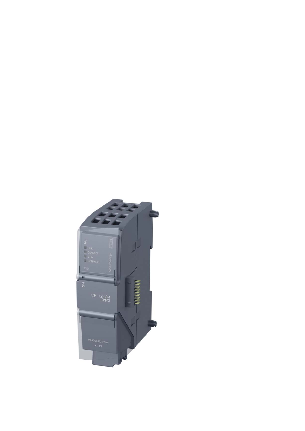
Figure 1 CP 1243-1 DNP3
3
Page 4

Preface
Product names and abbreviations
CP
DNP3-CP
IEC-CP
Purpose of the manual
New in this issue
The CP 1243-1 IEC has the same outer design as the CP 1243-1 DNP3 apart from the
inscriptions for the product name, article number, firmware version and possibly hardware
product version.
At the top right behind the hinged cover of the module housing, you will see the hardware
product version printed as a placeholder "X" after the article number. If the printed text is, for
example, "X 2 3 4", "X" would be the placeholder for hardware product version 1.
In this document, you will find the following designations used for the product being
described here:
●
Simplified naming of the two following products:
– CP 1243-1 DNP3
– CP 1243-1 IEC
This short form is used in this manual if the property being described in the particular
context applies to both modules.
●
Short form for the CP 1243-1 DNP3 (6GK7 243-1JX30-0XE0)
●
Short form for the CP 1243-1 IEC (6GK7 243-1PX30-0XE0)
This manual describes the properties of both these modules and supports you when
installing and commissioning them.
The required configuration steps are described as an overview and there are explanations of
the relationship between firmware functions and configuration.
You will also find information about the diagnostics options of the device.
● Inclusion of the CP 1243-1 IEC
● New firmware version of the DNP3 CP with bugs fixed
Make sure that the DNP3 CP with firmware version V1.0 or V1.1 is compatible with the
firmware of the CPU, refer to the section Hardware requirements (Page 17).
● Editorial revision
As a supplement to the STEP 7 information system, note the information on the functions
and parameters in the section Notes on configuring individual functions (Page 42).
CP 1243-1 DNP3, CP 1243-1 IEC
4 Operating Instructions, 02/2014, C79000-G8976-C312-02
Page 5

Preface
Replaced documentation
Current manual release on the Internet
Required experience
Requirements for use of the module
Sources of information and other documentation
SIMATIC NET glossary
This manual replaces the manual release 07/2013.
You will also find the current version of this manual on the Internet pages of Siemens
Industry Online Support in the directory of the relevant CP. This is located below the
directory with the following entry ID:
16514597 (http://support.automation.siemens.com/WW/view/en/16514597)
To install, commission and operate the CP, you require experience in the following areas:
● Automation engineering
● Setting up the SIMATIC S7-1200
● SIMATIC STEP 7 Basic / Professional
● DNP3 protocol or protocol according to IEC 60870-5
You will find the requirements for using the module in the section Hardware requirements
(Page 17).
You will find an overview of further reading and references in the Appendix of this manual.
Explanations of many of the specialist terms used in this documentation can be found in the
SIMATIC NET glossary.
You will find the SIMATIC NET glossary here:
● SIMATIC NET Manual Collection or product DVD
The DVD ships with certain SIMATIC NET products.
● On the Internet under the following entry ID:
50305045 (http://support.automation.siemens.com/WW/view/en/50305045)
CP 1243-1 DNP3, CP 1243-1 IEC
Operating Instructions, 02/2014, C79000-G8976-C312-02
5
Page 6

Preface
License conditions
Note
Open source software
Read the license conditions for open source software carefu
acceptance of the disclaimers of liability and warranty it contains is a clear precondition of
the use of open source software.
Security information
Training, Service & Support
lly before using the product. The
You will find license conditions in the following documents on the supplied data medium:
● DOC_OSS-S7CMCP_74.pdf
● DOC_OSS-CP1243-1DNP3-IEC_76.pdf
Siemens provides automation and drive products with industrial security functions that
support the secure operation of plants or machines. They are an important component in a
holistic industrial security concept. With this in mind, our products undergo continuous
development. We therefore recommend that you keep yourself informed with respect to our
product updates. Please find further information and newsletters on this subject at:
http://support.automation.siemens.com.
To ensure the secure operation of a plant or machine it is also necessary to take suitable
preventive action (e.g. cell protection concept) and to integrate the automation and drive
components into a state-of-the-art holistic industrial security concept for the entire plant or
machine. Any third-party products that may be in use must also be taken into account.
Please find further information at: http://www.siemens.com/industrialsecurity
You will find information on Training, Service & Support in the multi--language document
"DC_support_99.pdf" on the data medium supplied with the documentation.
CP 1243-1 DNP3, CP 1243-1 IEC
6 Operating Instructions, 02/2014, C79000-G8976-C312-02
Page 7

Table of contents
Preface ................................................................................................................................................... 3
1 Application and properties ....................................................................................................................... 9
2 Requirements for use ............................................................................................................................ 17
3 LEDs and connectors ............................................................................................................................ 19
4 Installation, connecting up, commissioning ............................................................................................ 25
5 Configuration and operation .................................................................................................................. 31
1.1 Communications services .............................................................................................................. 9
1.2 Other services and properties ...................................................................................................... 10
1.3 Configuration limits and performance data .................................................................................. 12
1.4 DNP3 device profile ..................................................................................................................... 13
1.5 Configuration examples ............................................................................................................... 14
1.5.1 Configuration with 1 subnet ......................................................................................................... 14
1.5.2 Configuration with connections over the Internet ......................................................................... 14
1.5.3 Configuration with a redundant control center ............................................................................. 16
2.1 Hardware requirements ............................................................................................................... 17
2.2 Software requirements ................................................................................................................. 18
3.1 Opening the covers of the housing .............................................................................................. 19
3.2 LEDs ............................................................................................................................................ 20
3.3 Electrical connections .................................................................................................................. 23
3.3.1 Power supply ................................................................................................................................ 23
3.3.2 Ethernet interface X1P1 ............................................................................................................... 23
4.1 Important notes on using the device ............................................................................................ 25
4.1.1 Notices on use in hazardous areas.............................................................................................. 25
4.1.2 Notices regarding use in hazardous areas according to ATEX ................................................... 26
4.1.3 Notices regarding use in hazardous areas according to UL HazLoc ........................................... 27
4.2 Installation .................................................................................................................................... 27
4.3 Installing, connecting up and commissioning .............................................................................. 29
5.1 Note on operation ........................................................................................................................ 31
5.2 Addressing and network configuration ......................................................................................... 31
5.3 Configuration in STEP 7 .............................................................................................................. 32
5.4 Configuring datapoints and messages (e-mails) ......................................................................... 33
5.5 Datapoint types ............................................................................................................................ 35
5.6 CPU scan cycle ............................................................................................................................ 38
5.7 Types of transmission, event classes, triggers ............................................................................ 39
CP 1243-1 DNP3, CP 1243-1 IEC
Operating Instructions, 02/2014, C79000-G8976-C312-02
7
Page 8

Table of contents
6 Diagnostics and upkeep ........................................................................................................................ 59
7 Technical specifications ........................................................................................................................ 63
A Approvals ............................................................................................................................................. 65
B Dimension drawings .............................................................................................................................. 69
C Documentation references .................................................................................................................... 71
Index .................................................................................................................................................... 73
5.8 Notes on configuring individual functions .................................................................................... 42
5.8.1 Communication types and SNMP ............................................................................................... 42
5.8.2 Ethernet interface (X1) > Advanced options ............................................................................... 43
5.8.3 Partner stations ........................................................................................................................... 46
5.8.4 Partner stations > Security options (DNP3) ................................................................................ 48
5.8.5 Communication with the CPU ..................................................................................................... 49
5.8.6 Data point configuration .............................................................................................................. 50
5.8.6.1 "General" parameter group ......................................................................................................... 50
5.8.6.2 Threshold value trigger and Analog value preprocessing ........................................................... 50
5.8.6.3 "Analog value preprocessing" parameter group ......................................................................... 51
5.8.6.4 Analog value preprocessing ........................................................................................................ 51
5.8.6.5 Threshold value trigger ............................................................................................................... 54
5.8.7 Configuring messages ................................................................................................................ 55
6.1 Diagnostics options ..................................................................................................................... 59
6.2 Downloading firmware ................................................................................................................. 59
6.3 Module replacement .................................................................................................................... 62
CP 1243-1 DNP3, CP 1243-1 IEC
8 Operating Instructions, 02/2014, C79000-G8976-C312-02
Page 9

1
1.1
Communications services
Communications services
DNP3-CP
DNP3 protocol
S7 communication and PG/OP communication with the following functions:
IEC-CP
Protocol IEC 60870-5
S7 communication and PG/OP communication with the following functions:
Status IDs of data points
The following communications services are supported:
●
Communication is based on the DNP3 SPECIFICATION Version 2.x (2007/2009).
The CP is a communications processor of the SIMATIC S7-1200 for system connection to
control centers using the DNP3 protocol for telecontrol applications.
An S7-1200 with CP 1243-1 DNP3 operates as a DNP3 station (Outstation).
The CP supports the implementation level 1 - 4 (DNP3 Application Layer protocol Level).
You will find a description of the other functions in the section Partner stations (Page 46).
●
– PUT/GET as client and server for data exchange with remote stations (S7-
300/400/1200/1500)
– PG functions
– Operator control and monitoring functions (HMI)
●
Communication is based on the specification IEC 60870-5 Part 1 - 5 (1990 - 1995) and
part 104 (2000).
The CP is a communications processor of the SIMATIC S7-1200 for system connection to
control centers using the IEC 60870-5 protocol for telecontrol applications.
An S7-1200 with CP 1243-1 IEC operates as a substation (slave).
●
– PUT/GET as client and server for data exchange with remote stations (S7-
300/400/1200/1500)
– PG functions
– Operator control and monitoring functions (HMI)
The status IDs listed in the following tables are transferred for each data point in each frame
in 1 byte.
The meaning relates to the bit status in the last row of each table.
CP 1243-1 DNP3, CP 1243-1 IEC
Operating Instructions, 02/2014, C79000-G8976-C312-02
9
Page 10

Application and properties
Bit
7 6 5 4 3 2 1
0
Flag name
FORCED
NUITY
RANGE
Meaning
value
Bit status
(always 0)
(always 0)
(always 0)
1 1 1 1 1
Bit
7 6 5 4 3 2 1
0
Flag name
substituted
carry
overflow
not topical
invalid
Meaning
value
Bit status
(always 0)
(always 0)
1
(always 0)
1 1 1
0
1.2
Other services and properties
Other services and properties
Data point configuration
Security functions (DNP3 only)
1.2 Other services and properties
Table 1- 1 DNP3: Byte assignment of the status byte for DNP3 data points
- - - LOCAL_-
- - - Local
operator
control
Table 1- 2 IEC: Byte assignment of the status byte for IEC data points
- - SB
- - Substitute
value
- CY
- Counted
DISCONTI-
Counted
value
overflow
before
reading the
value
overflow
before
reading the
OVER_-
Value
range
exceeded,
analog
value
OV
Value
range
exceeded,
analog
value
RESTART ONLINE
Value not
updated
after start
NT
Value not
updated
Value is
invalid
IV
Value is
invalid
●
Due to the data point configuration in STEP 7, programming program blocks in order to
transfer the process data is unnecessary. The individual data points are processed oneto-one in the control system.
●
The DNP3 CP can use the security functions specified in the DNP3 protocol and
therefore secure communication in the DNP3 network, including the following:
– Secure authentication (SA) of the communications partner
The DNP3 CP checks whether the communications partner has the right to access the
DNP3 CP.
Formation of the Message Authentication Code (MAC) using symmetrical (pre-shared
key, PSK) or asymmetrical cryptography (public/private keys)
Use of IPsec for transferring the key
– Logging of security events: Successful and failed authentication, key exchange,
statistical counters
You enable the security functions in the STEP 7 configuration with the required options.
CP 1243-1 DNP3, CP 1243-1 IEC
10 Operating Instructions, 02/2014, C79000-G8976-C312-02
Page 11

Application and properties
IP configuration - IPv4 and IPv6
Time-of-day synchronization over Industrial Ethernet
Redundancy
Storage of events
Data transfer is on request or triggered
Messages / e-mail
Analog value processing
1.2 Other services and properties
●
The essential features of IP configuration for the CP:
– The CP supports IP addresses according to IPv4 and IPv6.
– An IPv6 address can be used in addition to an IPv4 address.
– Address assignment:
The IP address, the subnet mask and the address of a gateway can be set manually
in the configuration.
As an alternative, the IP address can be obtained from a DHCP server or by other
means outside the configuration.
●
The CP can the have its local time of day synchronized by the partner (master) as UTC
time.
The time of day can be read from the CPU. The mechanisms are described in the STEP
7 information system.
For information on the format of the time stamp, refer to the section Datapoint types
(Page 35).
●
The CP can communicate with a redundant control system (master).
●
The CP can store events of different classes and transfer them together to the master.
●
The sending of data to the master can be triggered in two ways:
– At the request of the master
– Triggered by various selectable criteria
●
With configured events in the process image of the CPU, the CP can send messages as
e-mails. The data of the events to be sent by e-mail are configured using PLC tags.
●
Analog values can be preprocessed on the CP according to various methods.
CP 1243-1 DNP3, CP 1243-1 IEC
Operating Instructions, 02/2014, C79000-G8976-C312-02
11
Page 12

Application and properties
Online functions
SNMP
1.3
Configuration limits and performance data
Number of CMs/CPs per station
Connection resources
TCP connections to masters (DNP3 or IEC)
Online functions / TeleService
S7 connections
PG/OP connections
1.3 Configuration limits and performance data
●
From an engineering station (ES) on which STEP 7 is installed, you can use the online
functions of STEP 7 via the CP to access the S7-1200 CPU if the station is located in the
same IP subnet. The following online functions are available:
– Downloading project or program data from the STEP 7 project to the station
– Querying diagnostics data on the station
– Downloading firmware files to the CP
For a remote station located in a different IP subnet or that can be reached via the
Internet, these functions can only be used if the ES is connected to the station via a VPN
tunnel (for example via a SCALANCE S).
●
As an SNMP agent, the CP supports data queries using SNMP (Simple Network
Management Protocol) in version V1.
For more detailed information, refer to section Communication types and SNMP
(Page 42).
In each S7-1200 station, up to three CMs/CPs can be plugged in and configured; this means
a maximum of three identical CP 1243-1 DNP3 or three identical CP 1243-1 IEC modules.
●
The CP can establish connections to up to 4 masters. These can be single or redundant
masters.
In the case of 4 redundant masters, this would be 8 physical devices addressed using
different IP addresses.
●
1 connection resource is reserved for online functions / TeleService.
●
8 connection resources for S7 connections (PUT/GET)
●
– 1 connection resource for PG connections
– 3 connection resources for OP connections
CP 1243-1 DNP3, CP 1243-1 IEC
12 Operating Instructions, 02/2014, C79000-G8976-C312-02
Page 13

Application and properties
Number of data points for the data point configuration
User data
Frame memory (send buffer)
Messages / e-mail
1.4
DNP3 device profile
Detailed information on DNP3 attributes in the DNP3 device profile
1.4 DNP3 device profile
The maximum number of configurable data points is 200.
The data to be transferred by the CP is assigned to various data points in the STEP 7
configuration. The size of the user data per data point depends on the data type of the
relevant data point.
With the DNP3 CP, contiguous memory areas can be transferred up to a size of 64 bytes
using data point types of the object groups 110 (Octet String) and 111 (Octet String Event).
You will find details in the information system of STEP 7 and in the section Datapoint types
(Page 35).
The CP has a frame memory (send buffer) for data points configured as an event.
The send buffer has a maximum size of 64000 events divided into equal parts for all
configured communications partners. The size of the frame memory can be set in STEP 7,
refer to the section Communication with the CPU (Page 49).
You will find details of how the send buffer works (storing and sending events) as well as the
options for transferring data in the section Types of transmission, event classes, triggers
(Page 39).
Up to 10 messages can be configured in STEP 7 and sent as e-mails.
You will find a detailed overview of the attributes and properties specified in the DNP3
protocol and supported by the CP in the DNP3 device profile.
You will find the DNP3 device profile of the CP 1243-1 DNP3 on the Internet pages of
Siemens Industry Online Support under the following entry ID:
82856876 (http://support.automation.siemens.com/WW/view/en/82856876)
CP 1243-1 DNP3, CP 1243-1 IEC
Operating Instructions, 02/2014, C79000-G8976-C312-02
13
Page 14
Application and properties
1.5
Configuration examples
1.5.1
Configuration with 1 subnet
Configuration example with a non-redundant control center
1.5.2
Configuration with connections over the Internet
Configuration example with connections over the Internet
1.5 Configuration examples
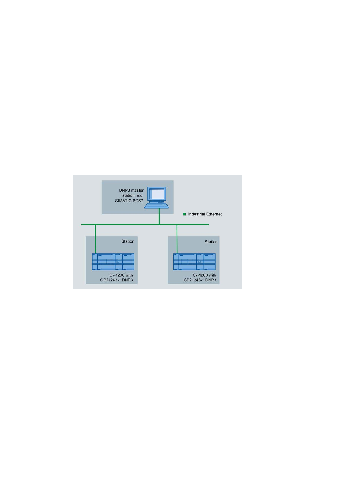
The following example describes a configuration with a non-redundant control center in
which all nodes are located in 1 IP subnet.
In this example, the DNP3 protocol is used; in other words, the stations are equipped with a
CP 1243-1 DNP3.
A configuration in which the IEC protocol is used would have the same setup apart from the
CP type (here CP 1243-1 IEC).
Figure 1-1 Configuration example with a non-redundant control center and stations in one IP subnet
The S7-1200 stations are connected to the Internet via the CP and connected to the control
center.
When using the DNP3 protocol, for example, SIMATIC PCS 7 TeleControl or the system of a
third-party provider can be used as the control center. If you use SIMATIC PCS 7
TeleControl as the DPN3 master in the control center, you require the necessary DPN3
driver.
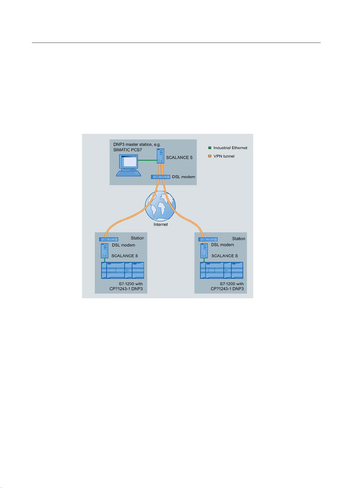
The following example contains a configuration with a non-redundant control center.
In this example, the DNP3 protocol is used; in other words, the stations are equipped with a
CP 1243-1 DNP3.
CP 1243-1 DNP3, CP 1243-1 IEC
14 Operating Instructions, 02/2014, C79000-G8976-C312-02
Page 15
Application and properties
Options of the Internet connection
1.5 Configuration examples
A configuration in which the IEC protocol is used would have the same setup apart from the
CP type (here CP 1243-1 IEC).
The S7-1200 stations are connected to the Internet via the CP and connected to the control
center.
When using the DNP3 protocol, for example, SIMATIC PCS 7 TeleControl or the system of a
third-party provider can be used as the control center. If you use SIMATIC PCS 7
TeleControl as the DPN3 master in the control center, you require the necessary DPN3
driver.
Figure 1-2 Configuration example with connections over the Internet
There are various ways of configuring the Internet connection:
● DSL modem + SCALANCE S
This is the configuration of the example shown in the figure.
In this case, use a standard DSL modem. With the security module SCALANCE S, you
establish the VPN connection.
● DSL router with VPN capability
In such a configuration, use a DSL router with VPN capability.
● Mobile wireless router
If the station needs to be connected to the Internet using mobile wireless (GSM network /
GPRS), the SIMATIC NET router SCALANCE M87x is used.
CP 1243-1 DNP3, CP 1243-1 IEC
Operating Instructions, 02/2014, C79000-G8976-C312-02
15
Page 16
Application and properties
Addressing
1.5.3
Configuration with a redundant control center
Configuration example with a redundant control center
Addressing of the redundant DNP3 master
1.5 Configuration examples
Refer to the information in the section Addressing and network configuration (Page 31).
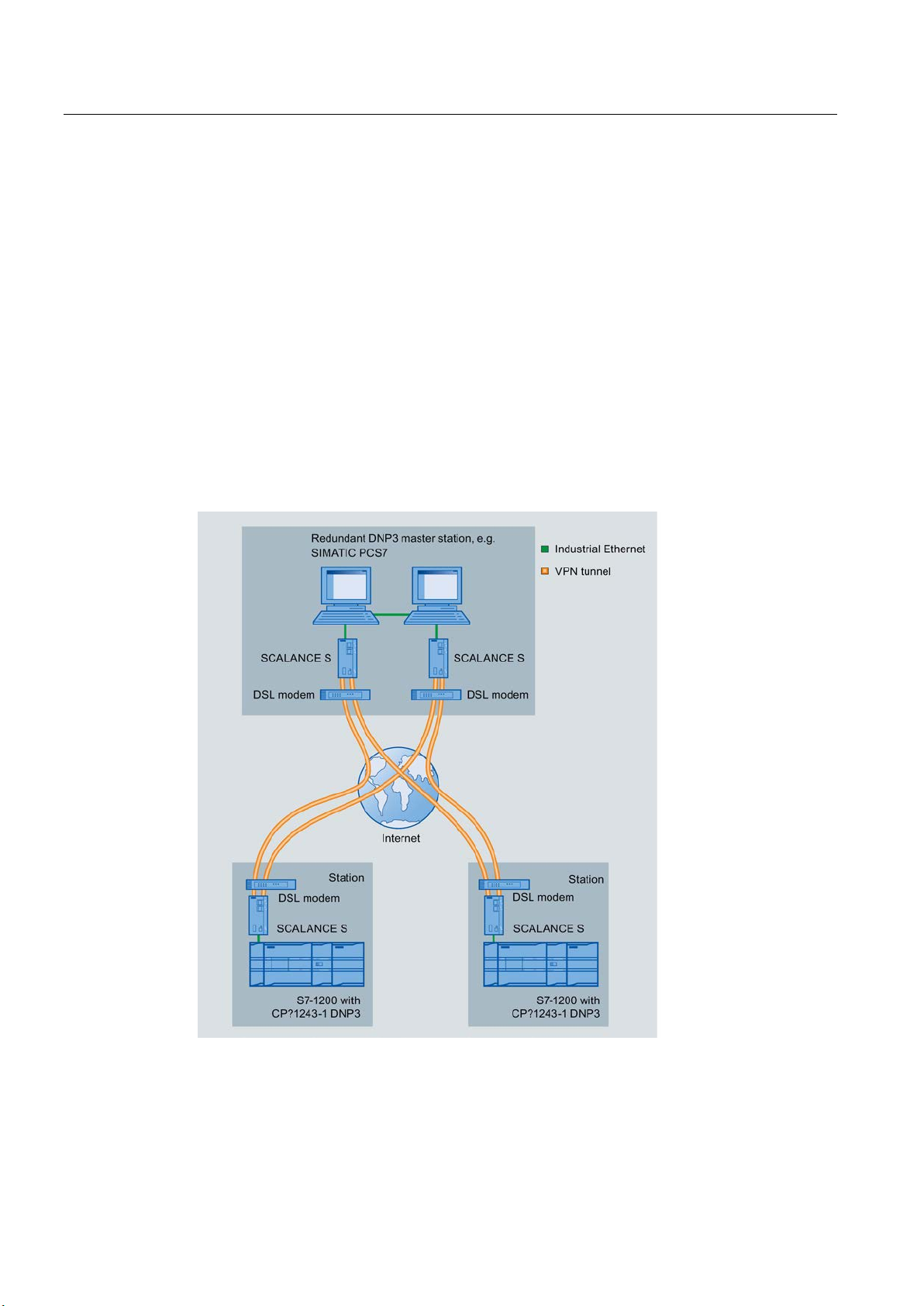
The following example contains a configuration with a redundant control center and
connections via the Internet.
In this example, the DNP3 protocol is used; in other words, the stations are equipped with a
CP 1243-1 DNP3.
A configuration in which the IEC protocol is used would have the same setup apart from the
CP type (here CP 1243-1 IEC).
Figure 1-3 Configuration example with a redundant DNP3 master station
The two devices of the redundant DNP3 master in the control center are addressed by the
DNP3 CP using one DNP3 address but two different IP addresses.
CP 1243-1 DNP3, CP 1243-1 IEC
16 Operating Instructions, 02/2014, C79000-G8976-C312-02
Page 17

2
2.1
Hardware requirements
Application example: Project with 1 subnet
In the S7-1200 station:
DNP3
IEC
In the master station:
Application example: Distributed project connections over the Internet
In the remote S7-1200 station:
DNP3
The following setups do not take into account rails, housing, cabling and other accessories.
Depending on the configuration of your plant, you require the following devices and firmware
versions.
The following setup assumes that the master and stations are located in 1 IP subnet, see
also the section Configuration with 1 subnet (Page 14).
●
– When using a DNP3 CP with firmware version V1.0: A CPU with firmware version
V3.0.
– When using a DNP3 CP with firmware version V1.1: A CPU with firmware version
V3.0 or V4.0.
●
– IEC CP
– CPU with firmware version V3.0 or V4.0
● PC for compatible DNP3 or IEC master
With redundantly designed master stations, the hardware needs to be doubled.
● When using online functions: Engineering station with STEP 7 (see following section)
The following set up assumes that the master and stations communicate via the Internet, see
also the section Configuration with connections over the Internet (Page 14).
●
– When using a DNP3 CP with firmware version V1.0: A CPU with firmware version
V3.0.
– When using a DNP3 CP with firmware version V1.1: A CPU with firmware version
V3.0 or V4.0.
– DSL router + SCALANCE S
See also the reference in the section "Notes on the DSL router" below.
CP 1243-1 DNP3, CP 1243-1 IEC
Operating Instructions, 02/2014, C79000-G8976-C312-02
17
Page 18

Requirements for use
IEC
In the master station:
Notes on the DSL router
2.2
Software requirements
Configuration software
Software for online functions
2.2 Software requirements
●
– IEC CP
– CPU with firmware version V3.0 or V4.0
– DSL router + SCALANCE S
See also the reference in the section "Notes on the DSL router" below.
● Compatible DNP3 or IEC master
● DSL router + SCALANCE S
See also the reference in the section "Notes on the DSL router" below.
● When using online functions: Engineering station with STEP 7 (see following section)
You will find the requirements for communication and the configuration options in the section
Configuration with connections over the Internet (Page 14).
To configure the modules, the following configuration tool is required:
● DNP3 CP with firmware version V1.0:
STEP 7 Basic ab V12.0 SP1
● DNP3 CP with firmware version V1.1:
STEP 7 Basic V13.0
● IEC CP with firmware version V1.1:
STEP 7 Basic V13.0
STEP 7 in the version specified above
CP 1243-1 DNP3, CP 1243-1 IEC
18 Operating Instructions, 02/2014, C79000-G8976-C312-02
Page 19
3
3.1
Opening the covers of the housing
Location of the display elements and the electrical connectors
Opening the covers of the housing
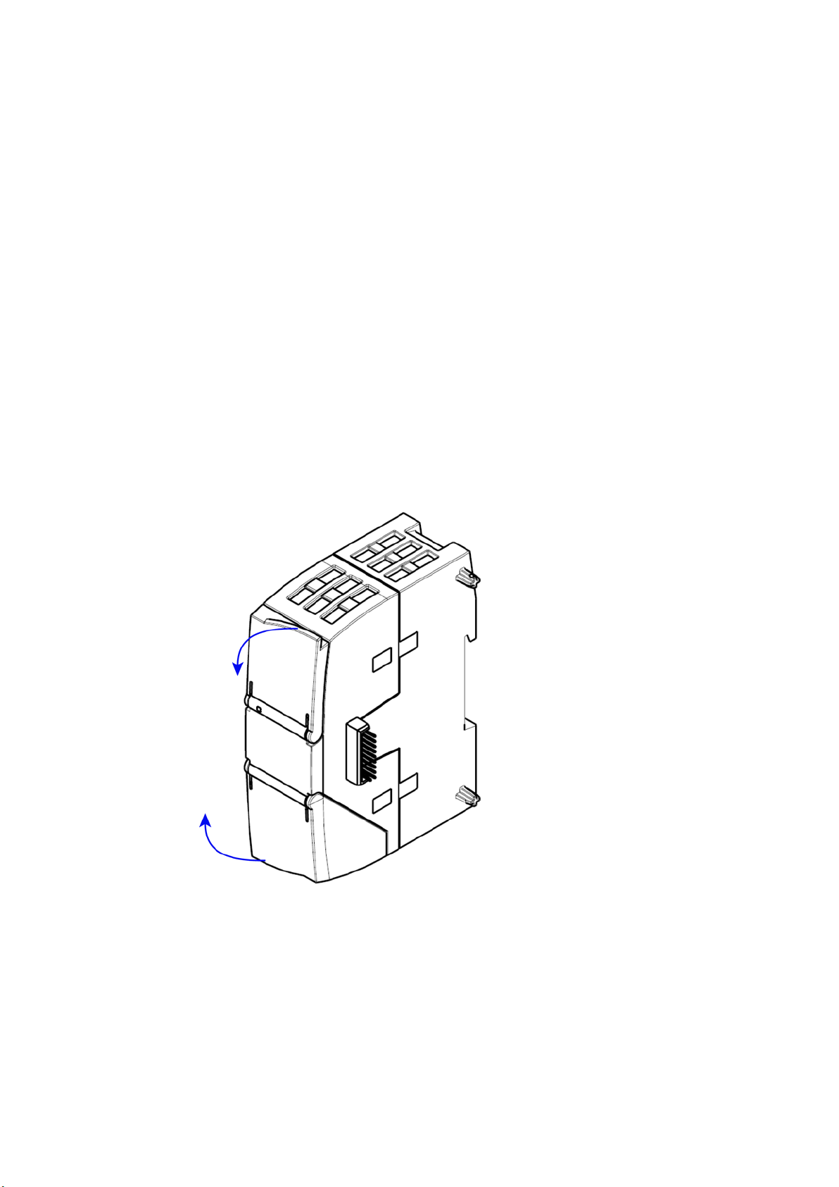
The LEDs for the detailed display of the module statuses are located behind the upper cover
of the module housing.
The Ethernet connector is located behind the lower hinged cover of the module.
Open the upper or lower cover of the housing by pulling it down or up as shown by the
arrows in the illustration. The covers extend beyond the housing to give you a grip.
Figure 3-1 Opening the covers of the housing
CP 1243-1 DNP3, CP 1243-1 IEC
Operating Instructions, 02/2014, C79000-G8976-C312-02
19
Page 20
LEDs and connectors
3.2
LEDs
LEDs of the module
LED on the front panel
LEDs below the upper cover of the housing
LED on the front panel
LED / colors
Name
Meaning
(red / green)
DIAG
LEDs below the upper cover of the housing
LED (color)
Name
Meaning
(green)
LINK
(green)
CONNECT
(green)
VPN
(green)
SERVICE
LED colors and illustration of the LED statuses
Meaning of the LED symbols
Symbol
LED status
OFF
ON (steady light)
Flashing
Not relevant
Note
LED colors when the module starts up
When
color mixture. At this point in time, the color of the LEDs is not clear.
3.2 LEDs
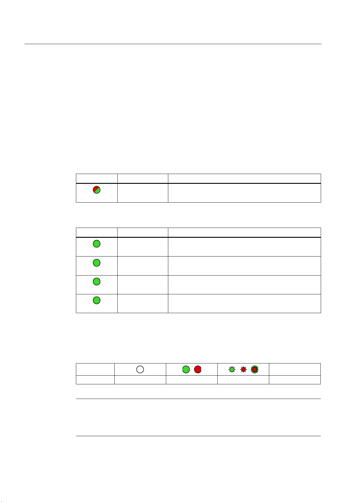
The module has various LEDs for displaying the status:
●
The "DIAG" LED that is always visible shows the basic statuses of the module.
●
The LEDs below the upper cover provide more detailed information on the module status.
Table 3- 1
Table 3- 2
Basic status of the module
Status of the connection to Industrial Ethernet
Status of the connections to masters
Status of a connection for online functions
- inactive -
The LED symbols in the following tables have the following significance:
Table 3- 3
the module starts up, all its LEDs are lit for a short time. Multicolored LEDs display a
CP 1243-1 DNP3, CP 1243-1 IEC
20 Operating Instructions, 02/2014, C79000-G8976-C312-02
-
Page 21
LEDs and connectors
Display of the basic statuses of the CP ("DIAG" LED)
DIAG
(red / green)
Meaning
(if more than one point listed: alternative meaning)
Basic statuses of the CP
green
flashing red-green
Display of the operating and communications statuses
DIAG
-
LINK
CONNECT
VPN
SERVICE
Meaning
(if more than one point listed: alternative
meaning)
Module startup (STOP → RUN)
Error/fault states
flashing red
green
red
3.2 LEDs
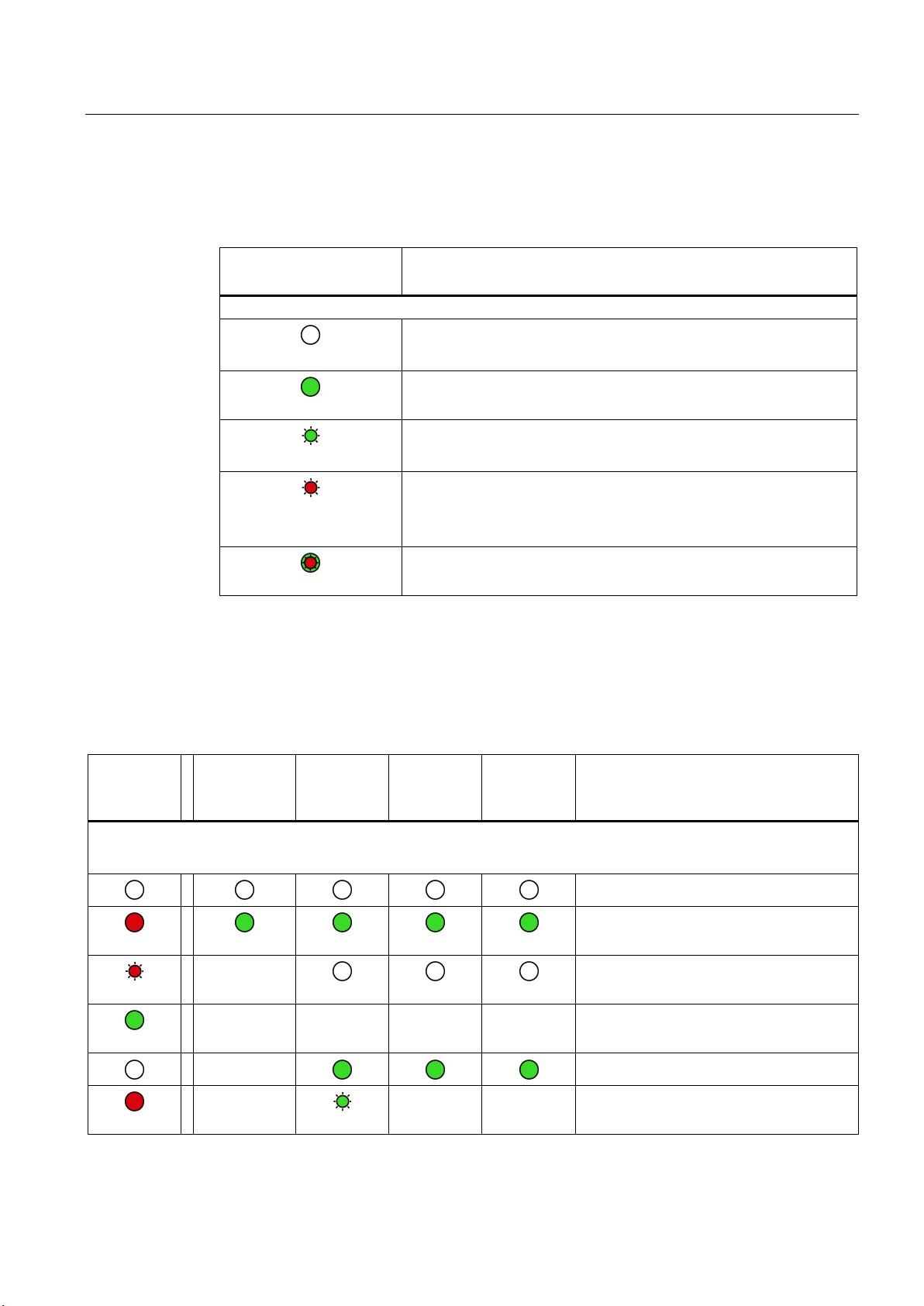
Table 3- 4 Display of the basic statuses of the CP
flashing green
flashing red
• Power OFF
• Incorrect startup
Running (RUN) without serious error
• Partner not connected
• Firmware loaded successfully
• Starting up
• Module fault
• Invalid STEP 7 project data
Error loading firmware
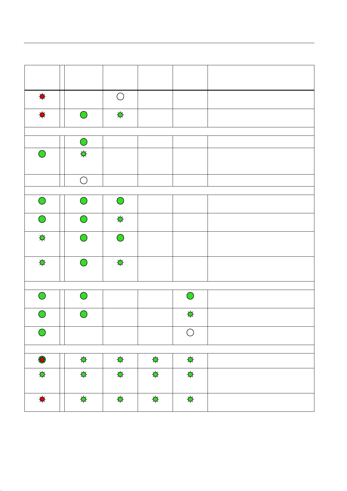
The LEDs indicate the operating and communications status of the module according to the
following scheme:
Table 3- 5 Display of the operating and communications statuses
(red / green)
•
•
red
CP 1243-1 DNP3, CP 1243-1 IEC
Operating Instructions, 02/2014, C79000-G8976-C312-02
(green)
-
- - - - Running (RUN) without serious error
-
(green)
(green)
- - Invalid STEP 7 project data
(green)
Power OFF
Startup - phase 1
Startup - phase 2
Incorrect startup
21
Page 22
LEDs and connectors
DIAG
-
LINK
CONNECT
VPN
SERVICE
Meaning
(if more than one point listed: alternative
meaning)
flashing red
flashing red
Connection to Industrial Ethernet
Connection to communications partners
green
green
green
green
Connection for online functions
green
green
green
Loading firmware
alternating red and green.
green
flashing red
3.3 Electrical connections
(red / green)
-
green
-
flashing
(green)
-
(green)
- - - Connection to Industrial Ethernet exists
- - -
- - - No connection to Industrial Ethernet
(green)
- - Missing STEP 7 project data
- - Backplane bus error
- - Connection established to at least one
- - Partner reachable, CPU in STOP mode
- - Partner not reachable, CPU in RUN mode
(green)
• Connection to Industrial Ethernet being
established.
• IP address being obtained.
partner
flashing
flashing
- - -
- -
- -
- - Partner not reachable, CPU in STOP mode
Connection for online functions established
Attempt to establish connection for online
functions
No connection to engineering station
Loading firmware. The DIAG LED flashes
Firmware was successfully loaded.
Error loading firmware
CP 1243-1 DNP3, CP 1243-1 IEC
22 Operating Instructions, 02/2014, C79000-G8976-C312-02
Page 23

LEDs and connectors
3.3
Electrical connections
3.3.1
Power supply
Power supply
3.3.2
Ethernet interface X1P1
Ethernet interface
3.3 Electrical connections
The CM is supplied with power from the backplane bus. It does not require a separate power
supply.
The Ethernet connector is located behind the lower hinged cover of the module. The
interface is an RJ-45 jack according to IEEE 802.3.
The pin assignment and other data relating to the Ethernet interface can be found in the
section Technical specifications (Page 63).
CP 1243-1 DNP3, CP 1243-1 IEC
Operating Instructions, 02/2014, C79000-G8976-C312-02
23
Page 24

LEDs and connectors
3.3 Electrical connections
CP 1243-1 DNP3, CP 1243-1 IEC
24 Operating Instructions, 02/2014, C79000-G8976-C312-02
Page 25

4
4.1
Important notes on using the device
Safety notices on the use of the device
Overvoltage protection
NOTICE
Protection of the external power supply
4.1.1
Notices on use in hazardous areas
WARNING
EXPLOSION HAZARD
WARNING
Note the following safety notices when setting up and operating the device and during all
associated work such as installation, connecting up or replacing the device.
If power is supplied to the module or station over longer power cables or networks, the
coupling in of strong electromagnetic pulses onto the power supply cables is possible. This
can be caused, for example by lightning strikes or switching of higher loads.
The connector of the external power supply is not protected from strong electromagnetic
pulses. To protect it, an external overvoltage protection module is necessary. The
manufacturers of industrial overvoltage protection devices produce suitable modules.
DO NOT OPEN WHEN ENERGIZED.
The equipment is designed for operation with Safety Extra-Low Voltage (SELV) by a
Limited Power Source (LPS).
This means that only SELV / LPS complying with IEC 60950-1 / EN 60950-1 / VDE 0805-1
must be connected to the power supply terminals. The power supply unit for the equipment
power supply must comply with NEC Class 2, as described by the National Electrical Code
(r) (ANSI / NFPA 70).
If the equipment is connected to a redundant power supply (two separate power supplies),
both must meet these requirements.
CP 1243-1 DNP3, CP 1243-1 IEC
Operating Instructions, 02/2014, C79000-G8976-C312-02
25
Page 26
Installation, connecting up, commissioning
WARNING
EXPLOSION HAZARD
WARNING
EXPLOSION HAZARD
WARNING
4.1.2
Notices regarding use in hazardous areas according to ATEX
WARNING
Requirements for the cabinet/enclosure
WARNING
WARNING
4.1 Important notes on using the device
DO NOT CONNECT OR DISCONNECT EQUIPMENT WHEN A FLAMMABLE OR
COMBUSTIBLE ATMOSPHERE IS PRESENT.
SUBSTITUTION OF COMPONENTS MAY IMPAIR SUITABILITY FOR CLASS I, DIVISION
2 OR ZONE 2.
When used in hazardous environments corresponding to Class I, Division 2 or Class I,
Zone 2, the device must be installed in a cabinet or a suitable enclosure.
To comply with EU Directive 94/9 (ATEX95), this enclosure must meet the requirements of
at least IP54 in compliance with EN 60529.
If the cable or conduit entry point exceeds 70 °C or the branching point of conductors
exceeds 80 °C, special precautions must be taken. If the equipment is operated in an air
ambient in excess of 50 °C, only use cables with admitted maximum operating temperature
of at least 80 °C.
Take measures to prevent transient voltage surges of more than 40% of the rated voltage.
This is the case if you only operate devices with SELV (safety extra-low voltage).
CP 1243-1 DNP3, CP 1243-1 IEC
26 Operating Instructions, 02/2014, C79000-G8976-C312-02
Page 27
Installation, connecting up, commissioning
4.1.3
Notices regarding use in hazardous areas according to UL HazLoc
WARNING
EXPLOSION HAZARD
4.2
Installation
Prior to installation and commissioning
CAUTION
Read the system manual "S7-1200 Programmable Controller"
Pulling/plugging the module
NOTICE
Turning off the station when plugging/pulling the module
4.2 Installation
DO NOT DISCONNECT WHILE CIRCUIT IS LIVE UNLESS AREA IS KNOWN TO BE
NON-HAZARDOUS.
This equipment is suitable for use in Class I, Division 2, Groups A, B, C and D or nonhazardous locations only.
This equipment is suitable for use in Class I, Zone 2, Group IIC or non-hazardous locations
only.
Prior to installation, connecting up and commissioning, read the relevant sections in the
system manual "S7-1200 Programmable Controller", refer to the documentation in the
Appendix.
When installing and connecting up, keep to the procedures described in the system manual
"S7-1200 Programmable Controller".
Before pulling or plugging the module, always turn off the power supply to the station.
CP 1243-1 DNP3, CP 1243-1 IEC
Operating Instructions, 02/2014, C79000-G8976-C312-02
27
Page 28

Installation, connecting up, commissioning
Dimensions for installation
S7-1200 devices
Width A
Width B *
CPU 1211C, CPU 1212C
90 mm
45 mm
CPU 1214C
110 mm
55 mm
CM 1241 RS-232 and CM 1241 RS-485
30 mm
15 mm
CM 1243-5, CM 1242-5 (PROFIBUS master / slave)
30 mm
15 mm
CP 1243-1 xxx
30 mm
15 mm
* Width B: The distance between the edge of the housing and the center of the hole in the DIN rail mounting clip
DIN rail clamps, control panel installation
4.2 Installation
Figure 4-1 Dimensions for installation of the S7-1200
Table 4- 1 Dimensions for installation (mm)
CPU (examples)
Communications
interfaces (examples)
CP 1242-7 30 mm 15 mm
You will find detailed dimensions of the module in the section Dimension drawings
(Page 69).
All CPUs, SMs, CMs and CPs can be installed on the 35 mm DIN rail in the cabinet. Use the
pull-out DIN rail mounting clips to secure the device to the rail. These mounting clips also
lock into place when they are extended to allow the device to be installed in a switching
panel. The inner dimension of the hole for the DIN rail mounting clips is 4.3 mm.
CP 1243-1 DNP3, CP 1243-1 IEC
28 Operating Instructions, 02/2014, C79000-G8976-C312-02
Page 29

Installation, connecting up, commissioning
Installation location
NOTICE
Installation location
Device position / permitted temperature range
Installation location
4.3
Installing, connecting up and commissioning
Requirement: Configuration prior to commissioning
Installing, connecting up and commissioning the module
Note
Connection with power off
Only wire up th
4.3 Installing, connecting up and commissioning
The module must be installed so that its upper and lower ventilation slits are not covered,
allowing adequate ventilation. Above and below the device, there must be a clearance of 25
mm to allow air to circulate and prevent overheating.
Remember that the permitted temperature ranges depend on the position of the installed
device.
Horizontal installation of the rack:
-20 °C to +70 °C
Vertical installation of the rack:
-20 °C to +60 °C
One requirement for the commissioning of the module is the completeness of the STEP 7
project data (see below, step 5). You should also read the section "Ethernet interface (X1) >
Advanced options (Page 43)".
CP 1243-1 DNP3, CP 1243-1 IEC
Operating Instructions, 02/2014, C79000-G8976-C312-02
e S7-1200 with the power turned off.
29
Page 30

Installation, connecting up, commissioning
Step
What to do
Notes and explanations
1
The slots to the left of the CPU are permitted.
2
Secure the DIN rail.
3
specifications (Page 63).
4
Turn on the power supply.
5
6
them closed during operation.
4.3 Installing, connecting up and commissioning
Table 4- 2 Procedure for installation and connecting up
Mount the CP on the DIN rail and connect it to
the module to its right.
Connect the Ethernet cable to the CP. You will find the pinout of the interface in the section Technical
The remaining steps in commissioning involve
downloading the STEP 7 project data.
Close the front covers of the module and keep
Use a 35 mm DIN rail.
The STEP 7 project data of the CP is transferred when you
load to the station. To load the station, connect the
engineering station on which the project data is located to the
Ethernet interface of the CPU.
You will find more detailed information on loading in the
following sections of the STEP 7 information system:
• "Loading project data"
• "Using online and diagnostics functions"
CP 1243-1 DNP3, CP 1243-1 IEC
30 Operating Instructions, 02/2014, C79000-G8976-C312-02
Page 31

5
5.1
Note on operation
NOTICE
Closing the front panels
5.2
Addressing and network configuration
Address information of the master
Configurations with connections over the Internet: VPN connections
To ensure interference-free operation, keep the front panels of the module closed during
operation.
To configure and commission the CP, the following information is required:
The following information is required for the STEP 7 configuration of the CP:
● Address of the master
– IP address
or
– Name that can be resolved with DNS
If you use DNS, there must be a DNS server (see below) and this must be reachable
for the CP.
● Port number of the listener port of the master
● DNS server address(es)
You require the DNS server address if you address the master using a name that can be
resolved by DNS.
For connections running via the Internet, dynamic IP addresses can be used.
CP 1243-1 DNP3, CP 1243-1 IEC
Operating Instructions, 02/2014, C79000-G8976-C312-02
To allow communication in both directions and to ensure that the data is protected during
transfer, a connection with a VPN tunnel is necessary. The security module SCALANCE S is
ideal for this purpose.
Remember the following points when configuring:
31
Page 32

Configuration and operation
5.3
Configuration in STEP 7
Configuration in STEP 7
Communication via redundant transmission paths
Communication with a redundant control system
How to configure in STEP 7
5.3 Configuration in STEP 7
● You configure the master IP address as normal.
● When configuring the CP interface, configure the IP address of the SCALANCE S as a
router address.
● You create the VPN configurations with SCALANCE S both for the station end and for the
control center end in STEP 7.
You configure the modules and networks in SIMATIC STEP 7. You will find the required
version in the section Hardware requirements (Page 17).
You can configure a maximum of three CMs/CPs per station.
If you insert several CPs in an S7-1200, you can establish redundant communications paths.
This is only possible if the control system supports redundant transmission paths to the
same station.
Even with a single DNP3 CP or IEC CP, an S7-1200 can communicate with a redundant
master.
The two devices of the redundant master are addressed by the CP using one DNP3 address
or one IEC address but two different IP addresses.
Follow the steps below when configuring:
1. Create a STEP 7 project.
2. Insert the required SIMATIC stations.
Configuration of the master stations and connections neither possible nor necessary.
3. Insert the CPs and the required input and output modules in the stations.
4. Create an Ethernet network.
5. Connect the stations to the Ethernet subnet.
6. Configure the inserted CPs.
For details on configuring the communication, refer to the following section.
7. Save the project.
You will find more detailed information on configuring the CP in the Information system of
STEP 7 and in the following sections.
CP 1243-1 DNP3, CP 1243-1 IEC
32 Operating Instructions, 02/2014, C79000-G8976-C312-02
Page 33

Configuration and operation
Requirement for configuring the communication
Loading and storing the configuration data
5.4
Configuring datapoints and messages (e-mails)
Data point-related communication
Requirement: Created PLC tags and/or data blocks (DBs)
Note
Number of PLC tags
Remember the maximum possible number of PLC tags the can be used for d
configuration in the section
Access to the memory areas of the CPU
5.4 Configuring datapoints and messages (e-mails)
One requirement for configuring communication between CP and control center is the
programming of the assigned CPU and the input and output data of the station.
PLC tags must also be created to assign the user data to the data points.
For more detailed information, refer to the following sections.
When you load the station, the project data of the station including the configuration data of
the CP is stored on the CPU.
You will find information on loading the station in the STEP 7 information system.
No program blocks need to be programmed for the CP to transfer user data between the
station and communications partner. The data areas in the memory of the CPU intended for
communication with the partner are configured data point-related on the CP. Each data point
is linked to a PLC tag or a data block on the CPU.
PLC tags or DBs must first be created in the CPU program to allow configuration of the data
points.
The PLC tags for data point configuration can be created in the standard tag table or in a
user-defined tag table. All PLC tags intended to be used for data point configuration must
have the attribute "Visible in HMI".
Address areas of the PLC tags are input, output or bit memory areas on the CPU.
Configuration limits and performance data (Page 12).
The formats and S7 data types of the PLC tags that are compatible with the protocol-specific
data point types of the CP can be found in the section Datapoint types (Page 35).
ata point
The values of the PLC tags or DBs referenced by the data points are read and transferred to
the communications partner by the CP.
CP 1243-1 DNP3, CP 1243-1 IEC
Operating Instructions, 02/2014, C79000-G8976-C312-02
33
Page 34

Configuration and operation
Configuring data points and messages in STEP 7
5.4 Configuring datapoints and messages (e-mails)
Data received from the communications partner is written by the CP to the CPU via the PLC
tags or DBs.
You configure the data points in STEP 7 in the Data point and alarm configuration. You can
find this using the project tree:
Project > directory of the relevant station > Local modules > CP 1243-1 xxx
Figure 5-1 Configuring data points and messages (e-mails)
Here, you will also find the editor for configuring messages.
You will find more detailed information on configuration in the following sections and in the
STEP 7 information system.
CP 1243-1 DNP3, CP 1243-1 IEC
34 Operating Instructions, 02/2014, C79000-G8976-C312-02
Page 35

Configuration and operation
5.5
Datapoint types
CP 1243-1 DNP3: Supported data point types
Format (memory
requirements)
Data point type
DNP3 object group
[variations]
Direction
S7 data types
Address area
Bit
Binary Input
1 [1, 2]
in
BOOL
I, Q, M, DB
Binary Input Event
2 [1, 2]
in
BOOL
I, Q, M, DB
Binary Output 1)
10 [2]
out
Binary Output Event 1)
11 [1, 2]
out
Binary Command
12 [1]
out
BOOL
I, Q, M, DB
Integer (16 bits)
Counter Static
20 [2]
in
UINT, WORD
I, Q, M, DB
Frozen Counter 2)
21 [2, 6]
in
Counter Event
22 [2, 6]
in
UINT, WORD
I, Q, M, DB
Frozen Counter Event 3)
23 [2, 6]
in
Analog Input
30 [2]
in
INT
I, Q, M, DB
Analog Input Event
32 [2]
in
INT
I, Q, M, DB
Analog Output Status 4)
40 [2]
out
Analog Output
41 [2]
out
INT
I, Q, M, DB
Analog Output Event 4)
42 [2, 4]
out
Integer (32 bits)
20
Frozen Counter 2)
21 [1, 5]
in
22
Frozen Counter Event 3)
23 [1, 5]
in
Analog Input
30 [1]
in
DINT
I, Q, M, DB
Analog Input Event
32 [1]
in
DINT
I, Q, M, DB
Analog Output Status 4)
40 [1, 3]
out
Analog Output
41 [1]
out
DINT
I, Q, M, DB
Analog Output Event 4)
42 [1]
out
Floating-point number
(32 bits)
Analog Input
30 [5]
in
REAL
Q, M, DB
Analog Input Event
32 [5, 7]
in
REAL
Q, M, DB
Analog Output Status 4)
40 [3]
out
Analog Output
41 [3]
out
REAL
Q, M, DB
Analog Output Event 4)
42 [5, 7]
out
5.5 Datapoint types
During the configuration of the user data to be transferred by the CP, each data point is
assigned a protocol-specific data point type. The data point types supported by the CP along
with the compatible S7 data types are listed below. They are grouped according to format
(memory requirements).
The direction relates to the direction of transfer (monitoring direction = "in", control direction
= "out").
Table 5- 1 Supported data point types, DNP3 object groups, variants and compatible S7 data types
Counter Static
Counter Event
[1] in UDINT,
DWORD
[1, 5] in UDINT,
DWORD
I, Q, M, DB
I, Q, M, DB
CP 1243-1 DNP3, CP 1243-1 IEC
Operating Instructions, 02/2014, C79000-G8976-C312-02
35
Page 36

Configuration and operation
Format (memory
requirements)
Data point type
DNP3 object group
[variations]
Direction
S7 data types
Address area
Floating-point number
(64 bits)
Analog Input
30 [6]
in
LREAL
Q, M, DB
Analog Input Event
32 [6, 8]
in
LREAL
Q, M, DB
Analog Output
41 [4]
out
LREAL
Q, M, DB
Analog Output Event 4)
42 [6, 8]
out
Block of data (1...64
bytes)
Octet String
110 [ - ]
in, out 5)
I, Q, M, DB
Octet String Event 5)
111 [ - ]
in, out 5)
I, Q, M, DB
1)
2)
3)
4)
5)
a size between 1 and 64 bytes are compatible. If the array is modified later, the data point must be recreated.
Explanation of the footnotes 1), 2), 3), 4): Configuring data points using substitute object groups
Configuration of the mirroring back for output events (object groups 11 and 42)
5.5 Datapoint types
5)
This object group can be configured in the Data point editor of STEP 7 using the substitute object group 12.
This object group can be configured in the Data point editor of STEP 7 using the substitute object group 20.
This object group can be configured in the Data point editor of STEP 7 using the substitute object group 22.
This object group can be configured in the Data point editor of STEP 7 using the substitute object group 41.
With these data point types, contiguous memory areas up to a size of 64 bytes can be transferred. All S7 data types with
The initial data point types of the following object groups can be configured using the
substitute object groups listed above:
● 10 [2]
● 11 [1, 2]
● 21 [1, 2, 5, 6]
● 23 [1, 2, 5, 6]
● 40 [1, 2, 3]
● 42 [1, 2, 4, 5, 6, 7, 8]
To configure the DNP3 CP, use the specified substitute object group.
Assign each data point on the master using the configurable data point index in STEP 7. The
data point of the DNP3 CP is then assigned to the corresponding data point on the master.
Example of configuring the data point Binary Output (10 [2])
The data point is configured as follows:
On the DNP3 CP as Binary Command (12 [1])
On the master as Binary Output (10 [2])
With the data point types Binary Output Event (11) and Analog Output Event (42) you also
need to enable mirroring back, refer to the next section.
You first create the data point types Binary Output Event (object group 11) and Analog
Output Event (object group 42) as described above as data points of the object groups 12 or
41.
The local values of these to object groups can be monitored for change and the changes
transferred to the master (reporting changes).
Changing a local value can, for example, be caused by manual operator input on site.
CP 1243-1 DNP3, CP 1243-1 IEC
36 Operating Instructions, 02/2014, C79000-G8976-C312-02
Page 37

Configuration and operation
Time stamp of the DNP3 CP in UTC format
CP 1243-1 IEC: Supported data point types
Format (memory
requirements)
Data point type
IEC type
Direction
S7 data types
Address area
Bit
Single point information
<1>
in
BOOL
I, Q, M, DB
Single command
<45>
out
BOOL
I, Q, M, DB
Byte
Step position information
<5>
in
BYTE
I, Q, M, DB
tag 1)
Regulating step command
<47>
out
BYTE
I, Q, M, DB
Integer (16 bits)
Measured value, normalized value
<9>
in
INT
I, Q, M, DB
with time tag 1)
Measured value, scaled value
<11>
in
INT
I, Q, M, DB
time tag 1)
value
Set point command, scaled value
<49>
out
INT
I, Q, M, DB
Integer (32 bits)
UDINT
UDINT
UDINT
5.5 Datapoint types
To allow the value resulting from local events or interventions to be transferred to the master,
the data point in question requires a channel for mirroring back.
This mirroring back function is enabled using the "Value monitoring (Reporting Changes)"
option in the STEP 7 configuration, refer to the section "General" parameter group
(Page 50).
Remember that to use the mirror back function, you need to interconnect the local values in
the controller with the relevant PLC tag of the data point.
Time stamps are transferred in UTC format (48 bits) and contain milliseconds since
01.01.1970.
Table 5- 2 Supported data point types, IEC types and compatible S7 data types
Single point information with time tag
1)
Step position information with time
Measured value, normalized value
Measured value, scaled value with
Set point command, normalised
Bitstring of 32 bits <7> in DWORD,
Bitstring of 32 bits with time tag 1) <33> in DWORD,
Integrated totals <15> in DWORD,
<30> in BOOL I, Q, M, DB
<32> in BYTE I, Q, M, DB
<34> in INT I, Q, M, DB
<35> in INT I, Q, M, DB
<48> out INT I, Q, M, DB
I, Q, M, DB
UDINT
I, Q, M, DB
I, Q, M, DB
CP 1243-1 DNP3, CP 1243-1 IEC
Operating Instructions, 02/2014, C79000-G8976-C312-02
Integrated totals with time tag 1) <37> in DWORD,
I, Q, M, DB
37
Page 38

Configuration and operation
Format (memory
requirements)
Data point type
IEC type
Direction
S7 data types
Address area
Floating-point
number (32 bits)
number
number with time tag 1)
point number
Block of data
(1...32 Bit)
Bitstring of 32 bits 2)
<7>
in 1)
I, Q, M, DB
Bitstring of 32 bits with time tag 1) 2)
<33>
in 1)
I, Q, M, DB
Bitstring of 32 bits 2)
<51>
out 1)
I, Q, M, DB
1)
2)
size between 1 and 32 bits are compatible. If the array is modified later, the data point must be recreated.
Time stamp with the IEC CP
5.6
CPU scan cycle
Structure of the CPU scan cycle
High-priority read jobs
Write jobs
5.6 CPU scan cycle
Measured value, short floating point
Measured value, short floating point
Set point command, short floating
1)
For information on the format of the time stamp, refer to the next section.
With these data point types, contiguous memory areas up to a size of 32 bits can be transferred. All S7 data types with a
<13> in REAL Q, M, DB
<36> in REAL Q, M, DB
<50> out REAL Q, M, DB
IEC CP time stamps are transferred according to the IEC specification in the "CP56Time2a"
format. Note that in the frames only the first 3 bytes for milliseconds and minutes are
transferred.
The cycle (including the pause) with which the CP scans the memory area of the CPU is
made up of the following phases:
●
For data points of the type "Input", which are configured with the "High priority" setting in
the data point configuration in "General > Priority in the scan cycle", the PLC tags are all
read in one scan cycle.
●
In every cycle, the values of a certain number of unsolicited write jobs are written to the
CPU. The number of tags written per cycle is specified for the CP in the "Communication
with the CPU" parameter group with the "Max. number of write jobs" parameter. The tags
whose number exceeds this value are then written in the next or one of the following
cycles.
CP 1243-1 DNP3, CP 1243-1 IEC
38 Operating Instructions, 02/2014, C79000-G8976-C312-02
Page 39

Configuration and operation
Low-priority read jobs - proportion
Cycle pause time
Duration of the CPU scan cycle
5.7
Types of transmission, event classes, triggers
Classification of the data points and storage of the values
No event / static value
Event
The image memory
5.7 Types of transmission, event classes, triggers
●
For data points of the type "Input", which are configured with the "Low priority" setting in
the data point configuration in "General > Priority in the scan cycle", the values of a part
of the PLC tags are read in every scan cycle.
The number of tags read per cycle is specified for the CP in the "Communication with the
CPU" parameter group with the "Max. number of read jobs" parameter. The tags that
exceed this value and can therefore not be read in one cycle are then read in the next or
one of the following cycles.
●
This is the waiting time between two scan cycles. It is used to reserve adequate time for
other processes that access the CPU via the backplane bus of the station.
Since no fixed time can be configured for the cycle and since the individual phases cannot
be assigned a fixed number of objects, the duration of the scan cycle is variable and can
change dynamically.
The values of data points are stored in the image memory of the CP and transferred only
when queried by the master. Events are also stored in the send buffer and can be
transferred unsolicited. All data points are therefore classified as follows:
●
Static values are entered in the image memory (process image of the CP).
●
The values of data points configured as an event are also entered in the image memory
of the CP. The value of the event is sent unsolicited to the communications partner if this
function is enabled by the master.
The values of events are also entered in the send buffer of the CP.
All the current values of the configured data points are stored in the image memory. New
values of a data point overwrite the last stored value in the image memory.
The values are sent after being queried by the communications partner. Refer to "Transfer
after call" in the section "Types of transmission".
CP 1243-1 DNP3, CP 1243-1 IEC
Operating Instructions, 02/2014, C79000-G8976-C312-02
39
Page 40

Configuration and operation
The send buffer
Types of transmission
Transfer after call
Event class
Event classes for the DNP3 protocol
Event class 1 / event class 2
Event class 3
5.7 Types of transmission, event classes, triggers
The send buffer is the data buffer on the CP for storing the values of events. The send buffer
has a maximum size of 64000 events. The configured number of events is divided equally
among all configured and enabled communications partners. The "Data buffer size"
parameter for the size of the send buffer is described in the section Communication with the
CPU (Page 49).
The frame memory operates chronologically; in other words, the oldest frames are sent first
(FIFO principle). When the maximum number of events is reached and the frames could not
be sent, the oldest values are overwritten.
If a connection to a communications partner is interrupted, the values of the events are
retained in the buffer. When the connection returns, the buffered frames are sent.
With the DNP3 CP, additional conditions for sending the events can be specified:
● A maximum number of events in the send buffer, configurable for each event class.
● A configurable maximum storage period for events in the send buffer.
This configuration of these conditions is described in the section Ethernet interface (X1) >
Advanced options (Page 43).
Depending on your CP type, you have the following transmission types available:
●
The current value of the data point is entered in the image memory of the CP. New
values of a data point overwrite the last stored value in the image memory.
After being called by the communications partner, the current value at the time is
transferred.
●
The value is entered in the send buffer triggered as an event. If unsolicited transfer is
enabled by the master, the value is transferred unsolicited.
You will find details of the event classes in the following sections.
The type of transmission is specified for each data point in the data point configuration in
STEP 7 with the "Type of transmission" or "Event class" parameter.
The process data of the various event classes is handled as follows:
●
Each value change is entered in the send buffer in chronological order.
The evaluation of the classification (1 or 2) must be handled by the master.
●
Only the current value at the time the trigger condition was met is entered in the image
memory and overwrites the last value stored there.
CP 1243-1 DNP3, CP 1243-1 IEC
40 Operating Instructions, 02/2014, C79000-G8976-C312-02
Page 41

Configuration and operation
Event classes for the IEC protocol
Every value triggered
Current value triggered
Trigger
Trigger types
Threshold value trigger
Time trigger
Event trigger
Resetting the trigger bit
Generation of events if a data point status changes
5.7 Types of transmission, event classes, triggers
The process data of the various event classes is handled as follows:
●
Each value change is entered in the send buffer in chronological order.
●
Only the current value at the time the trigger condition was met is entered in the image
memory and overwrites the last value stored there.
Various trigger types are available for event-driven transfer:
●
The value of the data point is transferred when this reaches a certain threshold. The
threshold is calculated as the difference compared with the last stored value, refer to the
section Threshold value trigger (Page 54).
●
The value of the data point is transferred at configurable intervals or at a specific time of
day.
●
The value of the data point is transferred when a configurable trigger signal is fired. For
the trigger signal, the edge change (0 → 1) of a trigger bit is evaluated that is set by the
user program. When necessary, a separate trigger bit can be configured for each data
point.
If the memory area of the trigger bit is in the bit memory or in a data block, the trigger bit is
reset to zero when the data point is transferred.
The status IDs of the data points described in the section Communications services (Page 9)
also cause event-driven transfer.
With data points that were configured as an event, a change in a status bit causes an event
to be generated and therefore results in unsolicited transfer.
Example: If the status "RESTART" or "NT" of a data point configured as an event changes to
"Value updated" when the station starts up, this causes the transfer of the value.
CP 1243-1 DNP3, CP 1243-1 IEC
Operating Instructions, 02/2014, C79000-G8976-C312-02
41
Page 42

Configuration and operation
5.8
Notes on configuring individual functions
Note
Information in STEP 7 and in the manual
If there are discrepancies between the following descriptions and the information in STEP 7 /
Professional V13, the in
5.8.1
Communication types and SNMP
"Communication types" parameter group
Enable DNP3 protocol / Activate telecontrol communication (IEC)
Activate online functions
Enabling S7 communication
Parameter group "SNMP"
Enable SNMP
SNMP (Simple Network Management Protocol)
5.8 Notes on configuring individual functions
Below, you will find information on the configuration of individual functions grouped
according to parameter groups in STEP 7.
formation in this document is valid.
In the two following parameter groups, you enable the types of communication of the CP.
To minimize the risk of unauthorized access to the station via Ethernet, you need to enable
the communications services that the CP will execute individually. You can enable all options
but at least one option should be enabled.
●
Enables communication using the DNP3 protocol or the IEC protocol on the CP.
●
Enables access to the CPU for the online functions via the CP (diagnostics, loading
project data etc.). If the function is enabled, the engineering station can access the CPU
via the CP.
If the option is disabled, you have no access to the CPU via the CP with the online
functions. Online diagnostics of the CPU with a direct connection to the interface of the
CPU however remains possible.
●
Enables S7 communication on the CP.
If you configure S7 connections to the relevant station, and these run via the CP, you will
need to enable this option.
●
Enables communication using SNMP on the CP.
SNMP is a protocol for managing networks. To transmit data, SNMP uses the
connectionless UDP protocol.
The information on the properties of SNMPcompliant devices is entered in MIB files (MIB =
Management Information Base).
CP 1243-1 DNP3, CP 1243-1 IEC
42 Operating Instructions, 02/2014, C79000-G8976-C312-02
Page 43

Configuration and operation
Range of performance of the CP as an SNMP agent
Access permissions using community name
Type of access
Community name *)
Read access
public
Read and write access
private
*) Note the use of lowercase letters!
5.8.2
Ethernet interface (X1) > Advanced options
Ethernet interface (X1) > Advanced options > TCP connection monitoring
5.8 Notes on configuring individual functions
The CP supports data queries using SNMP in version V1.
For the CP to support the object groups of the standard MIB-II:
● Supported object groups:
System, Interfaces, Address Translation (AT), IP, ICMP, TCP, UDP, SNMP
● Object groups not supported:
EGP, Transmission
Write access is permitted only for the following MIB objects of the "System" group:
● sysContact, sysLocation, sysName
A set sysName is sent as the host name using DHCP option 12 to the DHCP server to
register with a DNS server.
For all other MIB objects and MIB object groups, only read access is possible for security
reasons.
The CP does not support traps.
The CP uses the following community names to control the access rights in the SNMP
agent:
Table 5- 3 Access rights in the SNMP agent
The setting made here applies globally to all TCP connections of the CP.
With the DNP3 CP, note the option of overwriting the value configured here for individual
communications partners, refer to the section Partner stations (Page 46).
CP 1243-1 DNP3, CP 1243-1 IEC
Operating Instructions, 02/2014, C79000-G8976-C312-02
43
Page 44

Configuration and operation
Ethernet interface (X1) > Advanced options > Transfer settings
Transmission settings – DNP3
Buffer for class 1 / 2 / 3 events
Delay time class 1 / 2 / 3 events
Transmission settings - IEC 60870-5
Note
Settings on the master
When configuring the monitoring times t
settings on
Frame monitoring time
5.8 Notes on configuring individual functions
●
Here, for each of the three event classes you specify the number of events after which
the stored events are sent to the communications partner.
The maximum value from each event class is 64000.
Note: 64000 is also the value of the total size of the send buffer.
●
Here, for each of the three event classes you specify the maximum time the events can
be stored in the send buffer before they are sent to the communications partner.
You will find details of how the send buffer works (storing and sending events) as well as the
options for transferring data in the section Types of transmission, event classes, triggers
(Page 39).
and t2 make sure that you make the corresponding
1
the master so that there are no unwanted error messages or connection aborts.
●
(t1)
Monitoring time for the acknowledgement of frames sent by the IEC CP by the
communications partner. The monitoring time applies to all frames sent by the IEC CP in
I, S and U format.
If the partner does not send an acknowledgment during the monitoring time, the IEC CP
terminates the connection to the partner.
Permitted range: 0 ... 65535 s.
Default setting: 15 s
If you enter 0 (zero), the function is deactivated.
CP 1243-1 DNP3, CP 1243-1 IEC
44 Operating Instructions, 02/2014, C79000-G8976-C312-02
Page 45

Configuration and operation
Monitoring time for S and U frames
Idle time for test frames
Difference between send and receive sequence number
5.8 Notes on configuring individual functions
●
(t2)
Monitoring time for the acknowledgment of data frames of the master by the IEC CP.
After receiving data from the master, the CP acknowledges the received data as follows:
– If the CP sends data to the master itself within t
received from the master during t
at the same time along with the sent data frame (I
2
, it acknowledges the data frames
2
format).
– The CP sends an acknowledgment frame (S format) to the master of the latest when t
elapses.
Permitted range: 0 ... 65535 s
Default setting: 10 s
If you enter 0 (zero), the function is deactivated.
The value of t
●
should be less than that of t1.
2
(t3)
Monitoring time during which the IEC CP has not received any data from the master. This
parameter is intended for situations in which longer idle periods occur; in other words,
times when there is no data traffic.
When t
elapses, the IEC CP sends a test/control frame (U format) to the master and
3
enters a message in the diagnostics buffer of the CPU.
Permitted range: 0 ... 65535 s
Default setting: 30 s
If you enter 0 (zero), the function is deactivated.
●
2
The difference between the send sequence number and receive sequence number of a
frame.
The master returns the send sequence number of a frame from the CP that the sending
CP then saves as the receive sequence number. Frames whose send sequence number
is lower than the receive sequence number after the difference configured here is added
are evaluated as having been successfully transferred and are deleted from the send
buffer of the CP.
Permitted range: 1 ... 64
Default setting: 12
CP 1243-1 DNP3, CP 1243-1 IEC
Operating Instructions, 02/2014, C79000-G8976-C312-02
45
Page 46

Configuration and operation
5.8.3
Partner stations
Partner stations > "Partner 'X'"
Partner number
Master station address
Partner stations > Partner 'X' > "Connection to partner"
TCP connection monitoring time
Partner stations > Partner 'X' > "Advanced settings"
DNP3 level
5.8 Notes on configuring individual functions
●
The partner number is assigned by the system automatically and is used not to identify
only the master address but also the communications partner. The partner number is
required during configuration of the datapoints to assign the datapoints to a
communications partner.
●
Station address of the communications partner (master). The station address is required
to identify the master in the network.
The same station address must be assigned to the master during its own configuration.
– DNP3:
Note on SIMATIC PCS 7 as DNP3 master: The station address is configured there as
ASDU.
The TCP connection monitoring time is set for all TCP connections of the CP in the
parameter group of the Ethernet interface, see also the section Ethernet interface (X1) >
Advanced options (Page 43). These settings apply to all TCP connections of the CP.
With the DNP3 CP, it is also possible to set the globally set TCP connection monitoring time
separately for each individual partner:
●
The value set in the partner station of the DNP3 CP overwrites the global value for this
partner that was set in the parameter group "Ethernet interface (X1) > Advanced options
> TCP connection monitoring".
With the IEC CP, the monitoring time can only be set globally for the Ethernet interface and
are not for each individual communications partner.
●
Indicates the DNP3 implementation level supported by the CP
For the communication between the DNP3 CP and the master, the DNP3 level supported
by the master must be known.
For more detailed information, refer to the section Partner stations (Page 46).
CP 1243-1 DNP3, CP 1243-1 IEC
46 Operating Instructions, 02/2014, C79000-G8976-C312-02
Page 47

Configuration and operation
Report partner status
Partner stations > Partner 'X' > "Advanced settings" > DNP3 level (DNP3 only)
5.8 Notes on configuring individual functions
●
If the "Report partner status" function is enabled, the CP signals the status of the
communication to the remote partner.
– Bit 0 of "PLC tag for partner status" (data type WORD) is set to 1 if the partner can be
reached.
– Bit 1 is set to 1 if all the paths to the remote partner are OK (useful with redundant
paths).
– Bit 2 indicates the status of the send buffer (frame memory).
The following values are possible:
- 0: send buffer OK
- 1: send buffer threatening to overflow (more than 80 % full).
- 3: send buffer has overflowed (fill level 100 % reached).
As soon as the fill level drops below 50%, bit 3 is reset to 0.
Bits 3 to 15 of the PLC tags are not used and do not need to be evaluated in the program.
Various levels of protocol conformity are defined in the DNP3 protocol and they describe the
supported range of functions (subset) of a master or a station. These levels (implementation
levels) are known as "DNP3 Application Layer protocol Level" and abbreviated with
DNP3-L1 to DNP3-L4.
The selection of the level used by the DNP3 CP which must correspond to that of the
connected master is set separately in STEP 7 for each individual communications partner
(DNP3 master).
The CP supports the following implementation levels:
● DNP3-L1
● DNP3-L2
● DNP3-L3
● DNP3-L4
● DNP3-L5
The implementation level known here as DNP3L5 that is not specified in the standard
contains the range of functions of DNP3L4 and in addition support of the following DNP3
data types / variations:
– 64-bit analog value as floating-point number without time of day
– 64-bit analog value as floating-point number with time of day
– Counter event with time of day in 16-bit format
– Counter event with time of day in 32-bit format
CP 1243-1 DNP3, CP 1243-1 IEC
Operating Instructions, 02/2014, C79000-G8976-C312-02
47
Page 48

Configuration and operation
5.8.4
Partner stations > Security options (DNP3)
Partner stations > Partner 'X' > "Security options" (DNP3 CP only)
Preliminary remarks: Authentication and key exchange
Parameters
Key length
Max. number of key exchange requests
Authentication requests before key exchange
Key exchange interval
5.8 Notes on configuring individual functions
If the security function is enabled, the DNP3 master and station (DNP3 CP) authenticate
themselves with a secret key, the pre-shared key.
With the help of the common pre-shared key, after the first connection establishment
between master and DNP3 CP, session keys are agreed that are then renewed cyclically.
Renewal of the session keys is normally initiated by the master. The criteria for renewing the
key are specified in the following parameters.
● Key exchange interval
● Authentication requests before key exchange
As soon as one of these conditions is met, the session key is renewed.
These and several other parameters are explained below.
●
Specifies the length of the pre-shared key in bytes.
Permitted range: 16 ... 128. Depending on the secure hash algorithm configured in STEP
7 above, the following lengths are preset:
– For SHA-1: 16
– For SHA-256: 32
The value 0 (zero) is not permitted.
●
Maximum number of requests of a master within the key exchange interval configured
below. If the configured number of requests of the master is exceeded within the key
exchange interval, the DNP3 CP enters a message in the diagnostics buffer of the CPU.
Permitted range: 2 ... 255. Default setting: 5.
●
Maximum number of authentication requests of the DNP3 CP with the master. When this
number is reached, the session key is renewed. The value 0 (zero) is not permitted.
Recommendation: Set the number for the DNP3 CP twice as high as for the master.
●
Exchange interval for the session key. When time set for this interval is reached, the
session key is renewed.
If the key exchange interval is set to 0 (zero), the key is renegotiated according to the
configured "Authentication requests before key exchange".
Recommendation: Set the key exchange interval for the DNP3 CP twice as high as for
the master.
CP 1243-1 DNP3, CP 1243-1 IEC
48 Operating Instructions, 02/2014, C79000-G8976-C312-02
Page 49

Configuration and operation
Authentication timeout
Pre-shared key
5.8.5
Communication with the CPU
Communication with the CPU > "Data buffer size"
Data buffer size
5.8 Notes on configuring individual functions
●
Maximum waiting time for the response from the master to an authentication request of
the DNP3 CP.
Exceeding the wait time is evaluated as an error by the DNP3 CP. In this case, the DNP3
CP generates a security event and sends this to the master. The DNP3 CP does not
enter a message in the diagnostics buffer of the CPU.
Possible values: 0 ... 65535 s. For security reasons, avoid entering 0 (zero).
●
The pre-shared key can be configured in two ways:
– Manual configuration
Enter the pre-shared key in STEP 7 manually as a hexadecimal value.
– Import as file
Import the pre-shared key from the file system of the engineering station if the preshared key was generated by the master or another engineering system.
The pre-shared key of the DNP3 CP must be identical to the pre-shared key that the
master uses.
●
Here, you set the size of the send buffer for events.
A maximum of 64000 events divided up equally among the communications partners can
be buffered.
You will find details of how the send buffer works (storing and sending events) as well as the
options for transferring data in the section Types of transmission, event classes, triggers
(Page 39).
With the DNP3 CP, other conditions for the sending of events can be configured, refer to the
section Ethernet interface (X1) > Advanced options (Page 43).
CP 1243-1 DNP3, CP 1243-1 IEC
Operating Instructions, 02/2014, C79000-G8976-C312-02
49
Page 50

Configuration and operation
5.8.6
Data point configuration
5.8.6.1
"General" parameter group
"General" parameter group
Value monitoring (Reporting Changes) (DNP3 CP only)
Binary Output Event (11)
Analog Output Event (42)
5.8.6.2
Threshold value trigger and Analog value preprocessing
Sequence of processing Threshold value trigger and Analog value preprocessing
Note
Threshold value trigger: Calculation only after "Analog value preprocessing"
Note that the analog value preprocessing is performed before the check for a configured
threshold value.
This a
Threshold value trigger
Restricted preprocessing options if mean value generation is configured
If you configure mean value generation for an analog value event, the following
preprocessing options are not available:
•
•
•
No Threshold value trigger if Mean value generation is configured
If mean value generation is configured, no threshold value trigger can be configured for the
analog value event involved.
5.8 Notes on configuring individual functions
●
The option is available with the following data point types. The option must be enabled if
the data points are to be configured as an Output Event with mirroring back.
– Object group in STEP 7: Binary Output Command (12)
Object group with option enabled:
– Object group in STEP 7: Analog Output Command (41)
Object group with option enabled:
If the option is enabled, the value of the PLC tag of the data point configured as an output
is monitored for changes. If the value changes, for example as a result of operator input
on site, an event is generated and the changed value transferred to the master; in other
words mirroring back.
Refer to the information in the section Datapoint types (Page 35).
ffects the value that is configured for the threshold value trigger, refer to the section
(Page 54).
CP 1243-1 DNP3, CP 1243-1 IEC
50 Operating Instructions, 02/2014, C79000-G8976-C312-02
Unipolar transfer
Error suppression time
Smoothing
Analog inputs that are configured as an event are processed on the CP in the following
sequence:
Page 51

Configuration and operation
Sequence of analog value processing
-
-
5.8.6.3
"Analog value preprocessing" parameter group
Data point configuration - "Analog value preprocessing"
DNP3:
IEC:
5.8.6.4
Analog value preprocessing
Unipolar transfer
5.8 Notes on configuring individual functions
1. Reading the data from the input area of the CPU
2. Analog value preprocessing (part 1)
Processing involves the following steps:
– Mean value generation
Mean value generation configured: Calculation and then continued at point 4.
No mean value generation configured: Continue with "Unipolar transfer".
– Unipolar transfer (if configured)
– Error suppression time (if configured)
– Smoothing (if configured)
3. Threshold value calculation (if Threshold value trigger is configured)
4. Analog value preprocessing (part 2)
– Adjustment to the start of measuring range and end of measuring range (if configured)
5. Storage of the value in the send buffer
Transfer of the value to the partner if trigger and threshold value conditions are met.
With the following data point types, the analog input data can be preprocessed on the CP if
the data point is configured as an event:
●
– Analog Input Event (32) (16 bits)
●
– Measured value, scaled <11> / Measured value, scaled with time <35>
– Measured value, floating point <13> / Measured value, floating point with time <36>
Even if you do not configure any analog value preprocessing, keep the automatic threshold
value processing in mind, refer to the section Threshold value trigger (Page 54).
Depending on the data point type, the functions for analog value preprocessing described
below are supported.
If unipolar transfer is enabled, negative values of analog inputs are corrected to zero.
CP 1243-1 DNP3, CP 1243-1 IEC
Operating Instructions, 02/2014, C79000-G8976-C312-02
51
Page 52

Configuration and operation
Smoothing factor
Error suppression time
Recommendation for finished values that were preprocessed by the CPU:
5.8 Notes on configuring individual functions
Exception: The value -32768 / 8000h as fault ID for wire break of live zero hardware analog
inputs is transferred. With a software input, on the other hand, all values lower than zero are
corrected to zero.
If mean value generation is active, this parameter has no effect.
Analog values that fluctuate quickly can be smoothed with this function.
The smoothing factors are calculated according to the following formula as with S7 analog
input modules.
where
y
= smoothed value in the current cycle
n
= value acquired in the current cycle n
x
n
k = smoothing factor
The following values can be configured for the module as the smoothing factor.
● 1 = No smoothing
● 4 = Weak smoothing
● 32 = Medium smoothing
● 64 = Strong smoothing
If mean value generation is active, this parameter has no effect.
An analog value in the overflow range (32767 / 7FFFh) or underflow range (-32768 / 8000h)
is not transferred for the duration of the error suppression time. This also applies to live zero
inputs. The value in the overflow/underflow range is only sent after the error suppression
time has elapsed, if it is still pending.
If the value returns to the measuring range before the error suppression time elapses, the
current value is transferred immediately.
A typical use case for this parameter is the suppression of peak current values when starting
up powerful motors that would otherwise be signaled to the control center as a disruption.
The suppression is adjusted to analog values that are acquired by the S7 analog input
modules as raw values. These modules return the specified values for the overflow or
underflow range for all input ranges (also for live zero inputs).
If mean value generation is active, this parameter has no effect.
If the CPU makes preprocessed finished values available in bit memory or in a data block,
suppression is only possible or useful if these finished values also adopt the values listed
above 32767 / 7FFF
or -32768 / 8000h in the overflow or underflow range. If this is not the
h
case, the parameter should not be enabled for preprocessed values.
CP 1243-1 DNP3, CP 1243-1 IEC
52 Operating Instructions, 02/2014, C79000-G8976-C312-02
Page 53

Configuration and operation
Mean value generation
Set start of measuring range / Set end of measuring range
5.8 Notes on configuring individual functions
With this parameter, acquired analog values are transferred as mean values.
The current values of an analog data point are acquired cyclically and totaled. The number of
acquired values per time unit depends on the read cycle of the CPU and the CPU scan cycle
of the CP. The mean value is calculated from the accumulated values as soon as the
transfer is triggered by a time trigger. Following this, the accumulation starts again so that
the next mean value can be calculated.
The mean value can also be calculated if the transmission of the analog value message is
triggered by a request from the communications partner. The duration of the mean value
calculation period is then the time from the last transmission (for example triggered by the
trigger) to the time of the request. Once again, the accumulation restarts so that the next
mean value can be calculated.
If the acquired analog value is in the overflow range (32767 / 7FFF
(-32768 / 8000
), this value can either be taken into account immediately in the calculation of
h
the mean value or it can be suppressed for a specific period for the calculation of the mean
value. The required response can be decided with the Error suppression time parameter:
● Error suppression time = 0
Acquisition of a value in the overflow or underflow range results in the mean calculation
being stopped immediately. The value 32767 / 7FFF
invalid mean value for the current mean value calculation period and sent when the next
analog value frame is triggered. The calculation of a new mean value is then started. If
the analog value remains in the overflow or underflow range, this new value is again
saved immediately as an invalid mean value and sent when the next frame is triggered.
● Error suppression time > 0
If you have configured an error suppression time and then enable mean value generation,
the value of the error suppression time is grayed out but no longer used. If mean value
generation is enabled, the error suppression time is set to 0 (zero) internally.
In these two input boxes, you set a limit value at the start of the measuring range and at the
end of the measuring range and if these limits are violated, the transfer of a frame is
triggered. Configuration of a threshold value trigger is necessary for this function.
The range of the value that can be configured as a decimal number corresponds to the
measuring range of the analog module (-32768 ... 32767).
) or underflow range
h
or -32768 / 8000h is saved as an
h
By configuring these two values, you specify that the values of this analog value are
transferred as a frame only in the following situations:
● When called up by the master
● When the threshold value trigger fires
● When the value of "Set start of measuring range" is exceeded
● When the value of "Set end of measuring range" is undershot
The parameters "Set start of measuring range" and Set end of measuring range" are
pointless for measured values that have already been preprocessed in the CPU.
CP 1243-1 DNP3, CP 1243-1 IEC
Operating Instructions, 02/2014, C79000-G8976-C312-02
53
Page 54

Configuration and operation
Note
Evaluation of the value even when the option is disabled
If you enable one or both options and configure a value and then disable the option later, the
grayed out value is nevertheless evaluated.
To disable the two options, delete the previously configured values "Start of measuring
range" or "End of measuri
option.
Recommendation for quickly fluctuating analog values:
5.8.6.5
Threshold value trigger
Threshold value trigger: How the integrattion calculation works
The calculation cycle
5.8 Notes on configuring individual functions
ng range" from the input boxes and then disable the relevant
If the analog value fluctuates quickly, it may be useful to smooth the analog value first if the
"Set start of measuring range" and "Set end of measuring range" parameters are enabled.
This avoids a frame being sent every time a limit value is violated if the analog value
fluctuates close to one of the two limit values for a longer period of time.
The CP calculates the value for the threshold value trigger after the analog value
preprocessing, refer to the section Threshold value trigger and Analog value preprocessing
(Page 50).
To calculate the threshold value trigger, the integration method is used.
In the integration threshold value calculation, it is not the absolute value of the deviation of
the process value from the last stored value that is evaluated but rather the integrated
deviation.
The integration threshold value calculation works with a cyclic comparison of the integrated
current value with the last stored value. The calculation cycle in which the two values are
compared is 500 milliseconds.
(Note: The calculation cycle must not be confused with the scan cycle of the CPU memory
areas).
The deviations of the current process value are totaled in each calculation cycle. The trigger
is set only when the totaled value reaches the configured value of the threshold value trigger
and a new process value is entered in the send buffer.
The method is explained based on the following example in which a threshold value of 2.0 is
configured.
CP 1243-1 DNP3, CP 1243-1 IEC
54 Operating Instructions, 02/2014, C79000-G8976-C312-02
Page 55

Configuration and operation
Time [s]
(calculation
cycle)
Process value
stored in the send
buffer
Current process
value
Absolute deviation
from the stored
value
Integrated
deviation
0
20.0
20.0 0 0
0.5 20.3
+0.3
0.3
1.0 19.8
-0.2
0.1
1.5 20.2
+0.2
0.3
2.0 20.5
+0.5
0.8
2.5 20.3
+0.3
1.1
3.0 20.4
+0.4
1.5
3.5
20.5
20.5
+0.5
2.0
4.0 20.4
-0.1
-0.1
4.5 20.1
-0.4
-0.5
5.0 19.9
-0.6
-1.1
5.5 20.1
-0.4
-1.5
6.0
19.9
19.9
-0.6
-2.1
5.8.7
Configuring messages
Configuring e-mails
5.8 Notes on configuring individual functions
Table 5- 4 Example of the integration calculation of a threshold value configured with 2.0
In this example, a value of 2.0 was configured for the threshold value trigger.
With the changes in the process value shown in the example, the threshold value trigger
fires twice:
● At the time 3.5 s: The value of the integrated deviation is at 2.0. The new process value
● At the time 6.0 s: The value of the integrated deviation is at 2.1. The new process value
In this example, if a deviation of the process value of approximately 0.5 should fire the
trigger, then with the behavior of the process value shown here a threshold value of
approximately 1.5 ... 2.5 would need to be configured.
If important events occur, the CP can send e-mails to a communications partner.
You configure the e-mails in STEP 7 in the Data point and alarm configuration. You can find
this using the project tree:
Project > directory of the relevant station > Local modules > CP 1243-1
stored in the send buffer is 20.5.
stored in the send buffer is 19.9.
CP 1243-1 DNP3, CP 1243-1 IEC
Operating Instructions, 02/2014, C79000-G8976-C312-02
For the view in STEP 7, refer to the section Configuring datapoints and messages (e-mails)
(Page 33).
55
Page 56

Configuration and operation
Requirements and necessary information
Triggering e-mail transfer
Enable status identifier / External status
Status
Meaning
0000
Transfer completed free of errors
SMTP protocol.
cannot be set up at the same time.
8403
No TCP/IP connection could be established to the SMTP server.
5.8 Notes on configuring individual functions
Remember the following requirements in the CP configuration for the transfer of e-mails:
● It is necessary to enable the CP-specific type of communication:
– DNP3: "Enable DNP3 protocol"
– IEC: "Activate telecontrol communication (IEC)"
● The parameter group "E-mail configuration" needs to be configured.
To do this, you require the following information:
– Access data of the SMTP server: Address, port number, user name, password
– Email address of the recipient
One of the following events triggers sending of the e-mail:
● CPU changes to STOP.
● CPU changes to RUN.
● The connection to the partner is interrupted.
● The connection to the communications partner is re-established.
● A trigger signal is fired.
For the trigger signal to send the e-mail, the edge change (0 → 1) of a trigger bit is
evaluated that is set by the user program. When necessary, a separate trigger bit can be
configured for each e-mail.
If the memory area of the trigger bit is in the bit memory or in a data block, the trigger bit
is reset to zero when the e-mail is sent.
If this option is enabled in STEP 7, a status is output on the CP that provides information
about the processing status of the sent e-mail. The status is written to a PLC tag of the type
DWORD that is specified in the "External status" box.
The meaning of the statuses returned in hexadecimal format is as follows:
Table 5- 5 Meaning of the status ID output in hexadecimal format
82xx Other error message from the e-mail server
Apart from the leading "8", the message corresponds to the three-digit error number of the
8401 No channel available
Possible cause: There is already an e-mail connection via the CP. A second connection
CP 1243-1 DNP3, CP 1243-1 IEC
56 Operating Instructions, 02/2014, C79000-G8976-C312-02
Page 57

Configuration and operation
Status
Meaning
8405
The SMTP server has denied the login request.
SMTP client.
8407
Request to use SSL was denied.
8408
The client could not obtain a socket for creating a TCP/IP connection to the mail server.
reset the connection or the connection aborted.
reset the connection or the connection aborted.
8411
Sending the e-mail failed. Cause: There was not enough memory space for sending.
8412
The configured DNS server could not resolve specified domain name.
8413
Due to an internal error in the DNS subsystem, the domain name could not be resolved.
8414
An empty character string was specified as the domain name.
8415
An internal error occurred in the cURL module. Execution was aborted.
8416
An internal error occurred in the SMTP module. Execution was aborted.
8418
Sending the e-mail was aborted. Possible cause: Execution time exceeded.
8420
Certificate chain from the server could not be verified with the root certificate of the CP.
8421
Internal error occurred. Execution was stopped.
8450
Action not executed: Mailbox not available / unreachable. Try again later.
SMTP protocol.
Try sending e-mails without authentication (no user name).
the CP configuration.
5.8 Notes on configuring individual functions
8406 An internal SSL error or a problem with the structure of the certificate was detected by the
8409 It is not possible to write via the connection. Possible cause: The communications partner
8410 It is not possible to read via the connection. Possible cause: The communications partner
8417 Requests to SMTP on a channel already being used or invalid channel ID. Execution was
aborted.
8419 The channel was interrupted and cannot be used before the connection is closed.
84xx Other error message from the e-mail server
Apart from the leading "8", the message corresponds to the three-digit error number of the
8500 Syntax error: Command unknown.
This also includes the error of having a command chain that is too long. The cause may be
that the e-mail server does not support the LOGIN authentication method.
8501 Syntax error. Check the following configuration data:
Alarm configuration > E-mail data (Content):
• Recipient address ("To" or "Cc").
8502 Syntax error. Check the following configuration data:
Alarm configuration > E-mail data (Content):
• Email address (sender)
8535 SMTP authentication incomplete. Check the "User name" and "Password" parameters in
CP 1243-1 DNP3, CP 1243-1 IEC
Operating Instructions, 02/2014, C79000-G8976-C312-02
57
Page 58

Configuration and operation
Status
Meaning
8554
Transfer failed
SMTP protocol.
5.8 Notes on configuring individual functions
8550 SMTP server cannot be reached. You have no access rights. Check the following
configuration data:
• CP configuration > E-mail configuration:
– User name
– Password
– Email address (sender)
• Alarm configuration > E-mail data (Content):
– Recipient address ("To" or "Cc").
85xx Other error message from the e-mail server
Apart from the leading "8", the message corresponds to the three-digit error number of the
CP 1243-1 DNP3, CP 1243-1 IEC
58 Operating Instructions, 02/2014, C79000-G8976-C312-02
Page 59

6
6.1
Diagnostics options
LEDs of the module
STEP 7: The "Diagnostics" tab in the Inspector window
STEP 7: Diagnostics functions in the "Online > Online and diagnostics" menu
6.2
Downloading firmware
New firmware versions of the CP
The following diagnostics options are available.
For information on the LED displays, refer to the section LEDs (Page 20).
Here, you can obtain the following information on the selected module:
● Entries in the diagnostics buffer of the CPU
● Information on the online status of the module
Using the online functions, you can read diagnostics information from the CP from an
engineering station on which the project with the CP is stored. You obtain the following static
information on the selected module:
● General information on the module
● Diagnostics status
● Information on the Ethernet interface:
– Network
– Ethernet interface
– Statistics
If you want to operate online diagnostics with the station via the CP, you need to select
Activate online functions, see section Communication types and SNMP (Page 42).
You will find further information on the diagnostics functions of STEP 7 in the STEP 7
information system.
If a new firmware version is available for the module, you will find this on the Internet pages
of Siemens Industry Online Support under the following ID:
68853485 (http://support.automation.siemens.com/WW/view/en/68853485)
CP 1243-1 DNP3, CP 1243-1 IEC
Operating Instructions, 02/2014, C79000-G8976-C312-02
59
Page 60

Diagnostics and upkeep
Downloading the firmware via the Web server of the CPU
Requirements in the CPU configuration
Connection establishment with HTTP
Connection establishment with HTTPS
Connection establishment with HTTP
http
6.2 Downloading firmware
On the Internet page, select the "Entry list" tab and the "Download" entry type. You will find
the firmware file and a description of the procedure there.
Follow the steps below to connect to the Web server of the CPU and to download the CP's
new firmware file to the station.
1. Open the corresponding project on the engineering station.
2. Select the CPU of the station involved in STEP 7.
3. Select the "Web server" entry.
4. In the parameter group "General", select the "Enable Web server for this interface"
option.
5. With a CPU version V4.0 or higher, create a user in the user management with the name
"admin".
You need to assign the right to perform firmware updates in the access level.
The procedure for establishing a connection to the Web server depends on whether you
have enabled or disabled the "Allow access only using HTTPS" option in the "General"
parameter group:
●
Procedure if the "Allow access only using HTTPS" option is disabled
●
Procedure if the "Allow access only using HTTPS" option is enabled
These two variants are described in the following sections.
You will find the requirements for access to the Web server of the CPU (permitted Web
browser) and the description of the procedure in the STEP 7 information system under the
keyword "Information about the Web server".
1. Connect the PC on which the new firmware file is located to the CPU via the Ethernet
interface.
2. Enter the address of the CPU in the address box of your Web browser:
address>
3. Press the Enter key.
The start page of the Web server opens.
://<IP
4. Click on the "Download certificate" entry at the top right of the window.
The "Certificate" dialog opens.
CP 1243-1 DNP3, CP 1243-1 IEC
60 Operating Instructions, 02/2014, C79000-G8976-C312-02
Page 61

Diagnostics and upkeep
https
Connection establishment with HTTPS
http
Loading firmware
6.2 Downloading firmware
5. Download the certificate to your PC by clicking the "Install certificate ..." button.
The certificate is loaded on your PC.
You will find information on downloading a certificate in the help of your Web browser and
in the STEP 7 information system under the key words "HTTPS" or "Access for HTTPS
(S7-1200)".
6. When the connection has changed to the secure mode HTTPS ("
://<IP address>/..."
in the address box of the Web server), you can continue as described in the next section
"Downloading firmware".
If you terminate the connection to the Web server, the next time you can log in with the
Web server without downloading the certificate using HTTP.
1. Connect the PC on which the new firmware file is located to the CPU via the Ethernet
interface.
2. Enter the address of the CPU in the address box of your Web browser:
s://<IP
address>
3. Press the Enter key.
The start page of the Web server opens.
4. Continue as described in the following section "Downloading firmware".
1. Log in on the start page of the Web server as an administrator.
– User name: admin
– Password: No password necessary
2. After logging in, select the entry "Module status" in the navigation panel of the Web
server.
3. Select the CP in the module list.
4. Select the "Firmware" tab lower down in the window.
5. Browse for the firmware file on your PC using the "Browse..." button and download the file
to the station using the "Run update" button.
CP 1243-1 DNP3, CP 1243-1 IEC
Operating Instructions, 02/2014, C79000-G8976-C312-02
61
Page 62

Diagnostics and upkeep
6.3
Module replacement
Module replacement
CAUTION
Read the system manual "S7-1200 Programmable Controller"
6.3 Module replacement
Prior to installation, connecting up and commissioning, read the relevant sections in the
system manual "S7-1200 Programmable Controller" (refer to the documentation in the
Appendix).
When installing and connecting up, keep to the procedures described in the system manual
"S7-1200 Programmable Controller".
Make sure that the power supply is turned off when installing/uninstalling the devices.
The STEP 7 project data of the CP is stored on the local CPU. If there is a fault on the
device, this allows simple replacement of this communications module without needing to
load the project data to the station again.
When the station starts up again, the new CP reads the project data from the CPU.
CP 1243-1 DNP3, CP 1243-1 IEC
62 Operating Instructions, 02/2014, C79000-G8976-C312-02
Page 63

7
Technical specifications
Article numbers
Attachment to Industrial Ethernet
Quantity
1
Design
RJ-45 jack
autonegotiation, galvanically isolated
Transmission speed
10/100 Mbps
Permitted cable lengths (Ethernet)
(Alternative combinations per length range) *
Electrical data
Power supply
From the S7-1200 backplane bus
5 VDC
Current consumption (typical)
From the S7-1200 backplane bus
250 mA
Effective power loss (typical)
From the S7-1200 backplane bus
1.25 W
Permitted ambient conditions
installed horizontally
installed vertically
During storage
-40 ℃ to +70 ℃
During transportation
-40 ℃ to +70 ℃
Relative humidity
During operation
≤ 95 % at 25 °C, no condensation
Table 7- 1 Technical specifications of CP 1243-1 DNP3 and the CP 1243-1 IEC
• CP 1243-1 DNP3
• CP 1243-1 IEC
Properties 100BASE-TX, IEEE 802.3-2005, half duplex/full duplex, autocrossover,
0 ... 55 m
0 ... 85 m
0 ... 100 m
• 6GK7 243-1JX30-0XE0
• 6GK7 243-1PX30-0XE0
• Max. 55 m IE TP Torsion Cable with IE FC RJ45 Plug 180
• Max. 45 m IE TP Torsion Cable with IE FC RJ45 + 10 m TP Cord via
IE FC RJ45 Outlet
• Max. 85 m IE FC TP Marine/Trailing/Flexible/FRNC/Festoon/Food Cable with
IE FC RJ45 Plug 180
• Max. 75 m IE FC TP Marine/Trailing/Flexible/FRNC/Festoon/Food Cable +
10 m TP Cord via IE FC RJ45 Outlet
• Max. 100 m IE FC TP Standard Cable with IE FC RJ45 Plug 180
• Max. 90 m IE FC TP Standard Cable + 10 m TP Cord via IE FC RJ45 Outlet
Ambient temperature During operation with the rack
CP 1243-1 DNP3, CP 1243-1 IEC
Operating Instructions, 02/2014, C79000-G8976-C312-02
-20 °C to +70 °C
During operation with the rack
-20 °C to +60 °C
63
Page 64
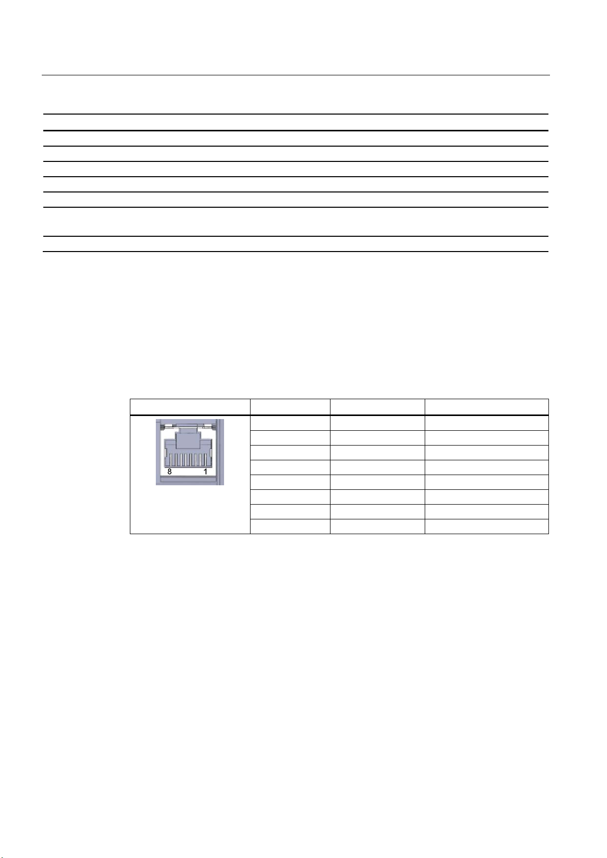
Technical specifications
Technical specifications
Design, dimensions and weight
Module format
Compact module for S7-1200, single width
Degree of protection
IP20
Weight
122 g
Dimensions (W x H x D)
30 x 110 x 75 mm
Switch panel
Product functions **
*
**
Pinout of the Ethernet interface
View of the RJ-45 jack
Pin
Signal name
Assignment
1
TD
Transmit data +
2
TD_N
Transmit data -
3
RD
Receive data +
4
GND
Ground
5
GND
Ground 6 RD_N
Receive data -
7
GND
Ground
Installation options Standard DIN rail
For details, refer to the IK PI catalog, cabling technology
You will find further characteristics and performance data in the section Application and
properties (Page 9).
The table below shows the pin assignment of the Ethernet interface. The pin assignment
corresponds to the Ethernet standard 802.3-2005, 100BASE-TX version.
Table 7- 2 Pin assignment of the Ethernet interface
8 GND Ground
CP 1243-1 DNP3, CP 1243-1 IEC
64 Operating Instructions, 02/2014, C79000-G8976-C312-02
Page 65

A
Current approvals on the Internet
Other approvals
Approvals issued
Note
Issued approvals on the type plate of the device
The specified approvals apply only wh
You can check which of the following approvals have been granted for your product by the
markings on the type plate.
EC declaration of conformity
SIMATIC NET products are regularly submitted to the relevant authorities and approval
centers for approvals relating to specific markets and applications.
You will also find the current approvals for the product on the Internet pages of Siemens
Automation Customer Support under the following entry ID:
68853485 (http://support.automation.siemens.com/WW/view/en/68853485)
→ "Entry list" tab, entry type "Certificates"
SIMATIC NET products are regularly submitted to the relevant authorities and approval
centers for approvals relating to specific markets and applications.
If you require a list of the current approvals for individual devices, consult your Siemens
contact or check the Internet pages of Siemens Automation Customer Support:
45605894 (http://support.automation.siemens.com/WW/view/en/22548697)
Under this entry, go to the relevant product and select the following settings: "Entry list" tab >
entry type "Certificates".
The CP has the following approvals and meets the following standards:
The CP meets the requirements and safety objectives of the following EU directives and it
complies with the harmonized European standards (EN) for programmable logic controllers
which are published in the official documentation of the European Union.
en the corresponding mark is printed on the product.
CP 1243-1 DNP3, CP 1243-1 IEC
Operating Instructions, 02/2014, C79000-G8976-C312-02
65
Page 66

Approvals
ATEX
● EC directive 2006/95/EEC "Electrical Equipment Designed for Use within Certain Voltage
Limits" (Low Voltage Equipment Directive)
● EN 60950-1 Information Technology Equipment - Safety
● EC Directive 2004/108/EC "Electromagnetic Compatibility" (EMC Directive)
– Emission
EN 61000-6-4:2007: Industrial area
– Immunity
EN 61000-6-2:2005: Industrial area
The EC Declaration of Conformity is available for all responsible authorities at:
Siemens Aktiengesellschaft
Industry Automation
Industrielle Kommunikation SIMATIC NET
Postfach 4848
D-90327 Nürnberg
Germany
You will find the EC Declaration of Conformity for this product on the Internet at the following
address:
68853485 (http://support.automation.siemens.com/WW/view/en/68853485) → tab "Entry list"
Filter settings:
Entry type: "Certificates"
Certificate Type: "Declaration of Conformity"
Search items(s): <name of the module>
ATEX approval: II 3 G Ex nA IIC T4 Gc
Relevant standards:
● EN 60079-0:2006: Potentially explosive atmosphere - general requirements
● EN 60079-15:2005: Electrical apparatus for explosive gas atmospheres; type of
protection 'n'
The device is suitable for use in environments with pollution degree 2.
The device is suitable for use only in environments that meet the following conditions:
● Class I, Division 2, Group A, B, C, D and areas where there is no risk of explosion
● Class I, Zone 2, Group IIC and areas where there is no risk of explosion
CP 1243-1 DNP3, CP 1243-1 IEC
66 Operating Instructions, 02/2014, C79000-G8976-C312-02
Page 67

Approvals
WARNING
Installation guidelines
cULus HAZ.LOC.
FM
C-Tick
The product meets the requirements if you keep to the following during installation and
operation:
• The notes in the section Important notes on using the device (Page 25)
• The installation instructions in the document /1/ (Page 71)
Over and above this, the following conditions must be met for the safe deployment of the CP:
● Install the modules in a suitable enclosure with degree of protection of at least IP54 to
EN 60529 and take into account the environmental conditions for operation of the
devices.
● If the rated temperatures of 70°C at the cable entry or 80°C at the branching point of the
wires are exceeded, the permitted temperature range of the selected cable must be
suitable for the actual measured temperatures.
● Measures must be taken to prevent the rated voltage being exceeded by more than 40%
due to transient disturbances.
Underwriters Laboratories Inc. meets
● Underwriters Laboratories, Inc.: UL 508 Listed (industrial control devices)
● UL 1604 (Hazardous Location)
● Canadian Standards Association: CSA C22.2 No 142 (process control equipment)
● CSA C22.2 No. 213 (Hazardous Location)
APPROVED for Use in:
● Cl. 1, Div. 2, GP. A, B, C, D T4A; Ta = -20 °C...60 °C
● Cl. 1, Zone 2, GP. IIC T4; Ta = -20 °C...60 °C
Factory Mutual Research (FM):
Approval Standard Class Number 3600 and 3611
approved for use in:
Class I, Division 2, Group A, B, C, D, Temperature Class T4A, Ta = 60 °C
Class I, Zone 2, Group IIC, Temperature Class T4, Ta = 60 °C
CP 1243-1 DNP3, CP 1243-1 IEC
Operating Instructions, 02/2014, C79000-G8976-C312-02
The CP meets the requirements of the AS/NZS 2064 standards (Class A)
67
Page 68

Approvals
CP 1243-1 DNP3, CP 1243-1 IEC
68 Operating Instructions, 02/2014, C79000-G8976-C312-02
Page 69
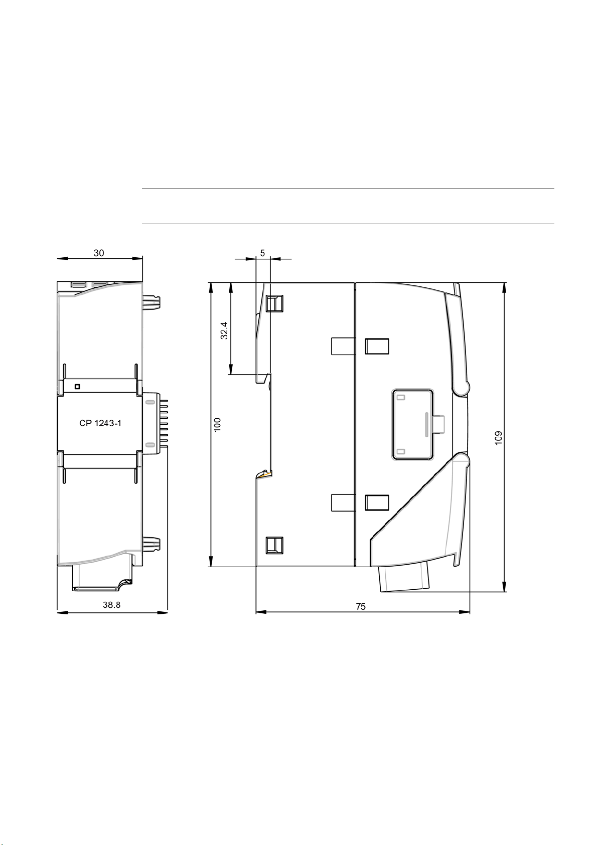
B
Note
All dimensions in the drawings are in millimeters.
Figure B-1 CP 1243-1 DNP3 / CP 1243-1 IEC: Front view and side view left
CP 1243-1 DNP3, CP 1243-1 IEC
Operating Instructions, 02/2014, C79000-G8976-C312-02
69
Page 70
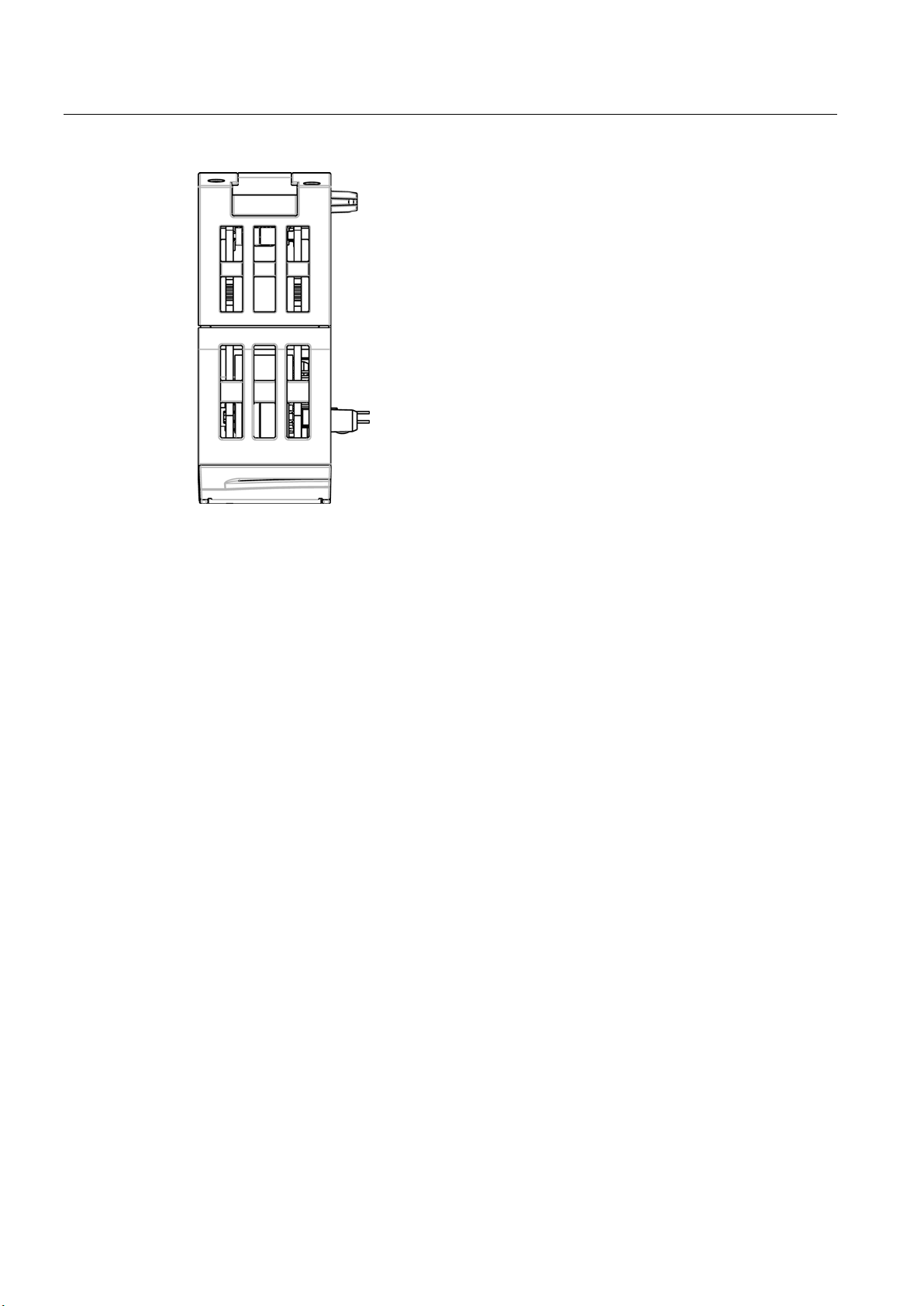
Dimension drawings
Figure B-2 CP 1243-1 DNP3 / CP 1243-1 IEC: View from above
CP 1243-1 DNP3, CP 1243-1 IEC
70 Operating Instructions, 02/2014, C79000-G8976-C312-02
Page 71

C
Where to find Siemens documentation
/1/
● You will find the order numbers for the Siemens products of relevance here in the
following catalogs:
– SIMATIC NET Industrial Communication / Industrial Identification, catalog IK PI
– SIMATIC Products for Totally Integrated Automation and Micro Automation, catalog
ST 70
You can request the catalogs and additional information from your Siemens
representative.
● You will find SIMATIC NET manuals on the Internet pages of Siemens Automation
Customer Support: Link to Customer Support
(http://support.automation.siemens.com/WW/view/en)
Enter the entry ID of the relevant manual as the search item. The ID is listed below some
of the reference entries in brackets.
As an alternative, you will find the SIMATIC NET documentation on the pages of Product
Support:
10805878 (http://support.automation.siemens.com/WW/view/en/10805878)
Go to the required product group and make the following settings:
"Entry list" tab, Entry type "Manuals / Operating Instructions"
You will find the documentation for the SIMATIC NET products relevant here on the data
medium that ships with some products:
– Product CD / product DVD or
– SIMATIC NET Manual Collection
SIMATIC
S7-1200 Programmable Controller
System Manual
Siemens AG
order number: 6ES7298-8FA30-8BH0
Current issue under the following entry ID:
34612486 (http://support.automation.siemens.com/WW/view/en/34612486)
CP 1243-1 DNP3, CP 1243-1 IEC
Operating Instructions, 02/2014, C79000-G8976-C312-02
71
Page 72

Documentation references
/2/
/2/
SIMATIC NET
CP 1243-1 DNP3, CP 1243-1 IEC
Operating Instructions
Siemens AG
entry ID: 69270828 (http://support.automation.siemens.com/WW/view/en/69270828)
CP 1243-1 DNP3, CP 1243-1 IEC
72 Operating Instructions, 02/2014, C79000-G8976-C312-02
Page 73

A
C
D
E
F
G
H
I
M
O
P
R
Abbreviations/acronyms, 4
Addressing - redundant master, 32
Analog value preprocessing, 51
Article number, 3
Communication, configuration, 33
Configuring communication, 33
Connection resources, 12
Data buffering, 13
Data point configuration, 33
Data point editor, 34
Dimensions, 28
DNP3 addressing, 31
DNP3 device profile, 13
DNP3 implementation level, 47
DNP3-L5, 47
DNS server, 31
Glossary, 5
Hardware product version, 3
IEC 60870-5, 3
IEC addressing, 31
Image memory, 39
Internet connections, 31
IP address (master), 31
IP address master (redundant), 32
IP configuration
IPv4, IPv6, 11
Message editor, 34, 55
Mirroring back, 36, 50
E-mail
Configuration, 34, 55
Number of messages, 13
Engineering station (ES), 12
ES - engineering station, 12
Ethernet interface
Assignment, 64
Event, 40
Event classes, 40
Events, 39
Firmware version, 3
Frame memory, 13
CP 1243-1 DNP3, CP 1243-1 IEC
Operating Instructions, 02/2014, C79000-G8976-C312-02
Online diagnostics, 42, 59
Online functions, 12, 59
Operating states, 21
PG/OP connections, 12
Pre-shared key (DNP3), 48
Priority of the read jobs, 38
Process image, 39
Product name, 4
PUT/GET, 12
Read jobs, 38
Redundant control system, 32
Redundant DNP3 master, addressing, 16
73
Page 74

Index
S
T
V
W
Replacing a module, 62
Reporting changes, 36, 50
Reset trigger bit, 41, 56
S7 connections
Enable, 42
Resources, 12
S7 data types, 33
Safety notices, 25
Security events, 10
Security options (DNP3), 48
Send buffer, 13, 40
Service & Support, 6
SIMATIC NET glossary, 5
SNMP, 12
Specifications, 9
Static event, 40
Static values, 39
Status ID - data points, 9
Status IDs - data points, 41
STEP 7 version, 18
Threshold value trigger, 54
Time stamp (DNP3 CP), 37
Time stamp IEC CP, 38
Time-of-day synchronization, 11
Training, 6
VPN, 31
Write jobs, 38
CP 1243-1 DNP3, CP 1243-1 IEC
74 Operating Instructions, 02/2014, C79000-G8976-C312-02
 Loading...