

Page 1
Page 2

Page 3
WARNING
Siemens products may only be used for the applications described in the catalog and in the
relevant technical documentation. If products and components from other manufacturers are
used, these must be recommended or approved by Siemens. Proper transport, storage,
installation, assembly, commissioning, operation and maintenance are required to ensure that
the products operate safely and without any problems. The permissible ambient conditions
must be complied with. The information in the relevant documentation must be observed.
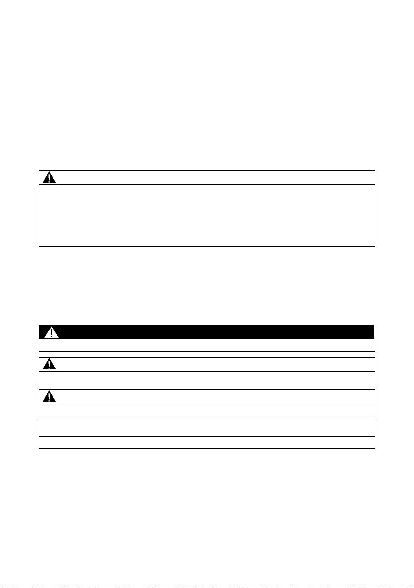
DANGER
indicates that death or severe personal injury will result if proper precautions are not taken.
WARNING
indicates that death or severe personal injury may result if proper precautions are not taken.
CAUTION
indicates that minor personal injury can result if proper precautions are not taken.
NOTICE
indicates that property damage can result if proper precautions are not taken.
Legal information
Qualified Personnel
The product/system described in this documentation may be operated only by personnel
qualified for the specific task in accordance with the relevant documentation, in particular its
warning notices and safety instructions. Qualified personnel are those who, based on their
training and experience, are capable of identifying risks and avoiding potential hazards when
working with these products/systems.
Proper use of Siemens products
Note the following:
Warning notice system
This manual contains notices you have to observe in order to ensure your personal safety, as
well as to prevent damage to property. The notices referring to your personal safety are
highlighted in the manual by a safety alert symbol, notices referring only to property damage
have no safety alert symbol. These notices shown below are graded according to the degree of
danger.
If more than one degree of danger is present, the warning notice representing the highest
degree of danger will be used. A notice warning of injury to persons with a safety alert symbol
may also include a warning relating to property damage.
© Siemens AG 2011 - 2013. All rights reserved
A5E03275848-04, 05/2013 1
Page 4

Table of contents
1 Introduction ..................................................................................................3
2 Safety notes .................................................................................................3
3 Description ...................................................................................................4
3.1 Product characteristics ......................................................................... 4
3.2 Unpacking and checking ...................................................................... 5
4 Mounting ......................................................................................................6
4.1 19" rack mounting of the PS598-1 ........................................................ 6
4.2 Mounting the PS598-1 on the rear panel of an XR500 ......................... 8
5 Connection ................................................................................................ 11
5.1 Connecting devices with 100 to 240 VAC power supply .................... 11
5.2 LED display ........................................................................................ 16
6 Upkeep and maintenance ........................................................................... 17
7 Technical data ............................................................................................ 18
8 Dimension drawings ................................................................................... 19
9 Approvals ................................................................................................... 20
9.1 EMC directive ..................................................................................... 20
9.2 Mechanical stability (in operation) ...................................................... 22
Power supply unit PS598-1 for SCALANCE XR500
2 A5E03275848-04, 05/2013
Page 5
DANGER
Danger from line voltage
Devices with this mark have a 100 to 240 VAC power supply.
This product can only function correctly and safely if it is transported, stored, set up,
and installed correctly, and operated and maintained as recommended.
Connecting and disconnecting may only be performed by an electrical specialist.
Connect or disconnect power supply cables only when the power is turned off!
WARNING
Opening the device
Do not open when energized. Note that this does not apply to opening the panel in
the housing.
1 Introduction
Purpose of the compact operating instructions
Based on the compact operating instructions, you will be able to install and connect
up the PS598-1 correctly.
Validity of these compact operating instructions
These compact operating instructions apply to the product PS598-1 as of product
version 1.
2 Safety notes
Safety notices on the use of the devices
The following safety notices must be adhered to when setting up and operating the
device and during all work relating to it such as installation, connecting up, replacing
devices or opening the device.
Important notices 100 to 240 VAC
General notices
Power supply unit PS598-1 for SCALANCE XR500
A5E03275848-04, 05/2013 3
Page 6

Type
Power
Input voltage
Output voltage
PS598-1
300 W
100 to 240 VAC
24 VDC
Note
Two connectors for the 24 VDC output voltage
The PS598-1 has two connectors with the output voltage 24 VDC. Note that you can
only use one connector on the front or the connector on the rear of the PS598-1. You
cannot operate the device with the connectors on the front and rear at the same time.
Note
Requirement for connecting at the rear
Note that the connector on the rear of the PS598-1 can only be used if the power
supply is mounted on the SCALANCE XR500.
3 Description
3.1 Product characteristics
Connectors
Components of the product
The following parts make up the components of the PS598-1:
● 4-pin terminal block for the 24 VDC power supply.
● 2 mounting brackets
● 8 screws (M3 x 6 countersunk, drive: Torx) for mounting the fixing brackets for
19" rack installation
● Compact Operating Instructions
Power supply unit PS598-1 for SCALANCE XR500
4 A5E03275848-04, 05/2013
Page 7
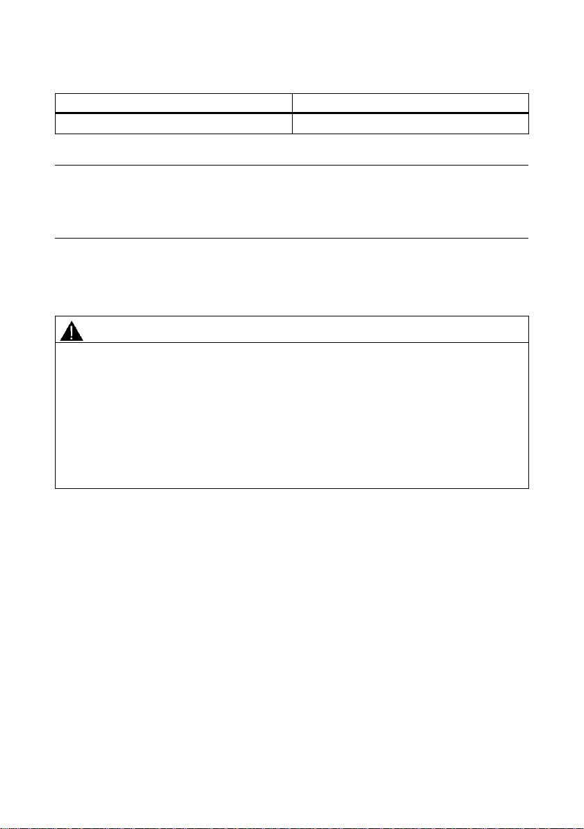
Order numbers
Type
Order number
PS598-1 (300 W)
6GK5 598-1AA00-3AA0
Note
Replacing the filter mat
To replace the filter mat, use the material Viledon P 15/150 G2 EN 779. The
dimensions of the filter mat are 38 x 135 x 8 mm (H x W x D).
WARNING
Do not use any parts that show evidence of damage
If you use damaged parts, there is no guarantee that the device will function
according to the specification.
If you use damaged parts, this can lead to the following problems:
● Injury to persons
● Loss of the approvals
● Violation of the EMC regulations
Use only undamaged parts.
3.2 Unpacking and checking
Description
1. Make sure that the package is complete.
2. Check all the parts for transport damage.
If the consignment is incomplete or if there is damage to the exterior, contact your
supplier or your local Siemens office.
Power supply unit PS598-1 for SCALANCE XR500
A5E03275848-04, 05/2013 5
Page 8
CAUTION
Risk of injury if subjected to irregular mechanical strain
The device must be mounted in the rack so that even if there is irregular mechanical
strain, no dangerous situation can result.
NOTICE
Damage to the device due to inadequate cooling
If the ventilation grilles are fully or partly covered or the air filters are contaminated,
the temperature inside the housing can rise and exceed the maximum permitted
temperature and damage the device.
During installation, select a mounting position so that the ventilation grilles are
always free so that the air can circulate. The ventilation grilles are located on the
side panels of the housing. You will find information about cleaning the air filter in
the section "Upkeep and maintenance".
4 Mounting
4.1 19" rack mounting of the PS598-1
Power supply unit for 19" rack installation
The PS598-1 was developed specifically for use with devices of the XR500 product
group. This power supply unit can be mounted directly above or below a SCALANCE
XR500 since the ventilation grilles are on the sides of both the basic device and the
power supply unit.
Power supply unit PS598-1 for SCALANCE XR500
6 A5E03275848-04, 05/2013
Page 9
Procedure
Mounting
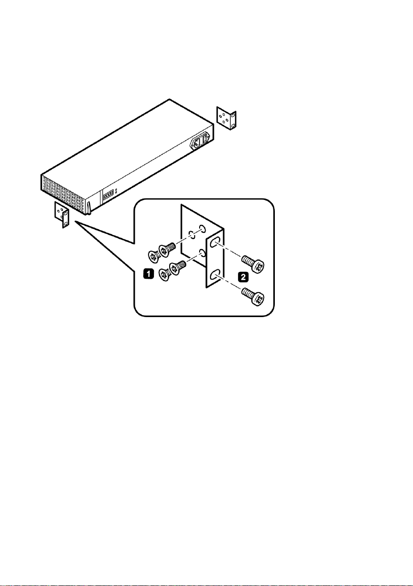
Follow the steps below to install the PS598-1 in a 19" rack:
1. Secure the two mounting brackets with four screws each (M3 x 6 supplied with
the product) to the side panels of the power supply unit. The maximum tightening
torque for these screws is 0.5 Nm.
2. Screw the PS598-1 to the 19" rack.
Power supply unit PS598-1 for SCALANCE XR500
A5E03275848-04, 05/2013 7
Page 10

Mounting
NOTICE
Damage to the device due to inadequate cooling
If the ventilation grilles are fully or partly covered or the air filters are contaminated,
the temperature inside the housing can rise and exceed the maximum permitted
temperature and damage the device.
During installation, select a mounting position so that the ventilation grilles are
always free so that the air can circulate. The ventilation grilles are located on the
side panels of the housing. You will find information about cleaning the air filter in
the section "Upkeep and maintenance".
4.2 Mounting the PS598-1 on the rear panel of
an XR500
Power supply unit PS598-1 for SCALANCE XR500
8 A5E03275848-04, 05/2013
Page 11
Procedure
Mounting
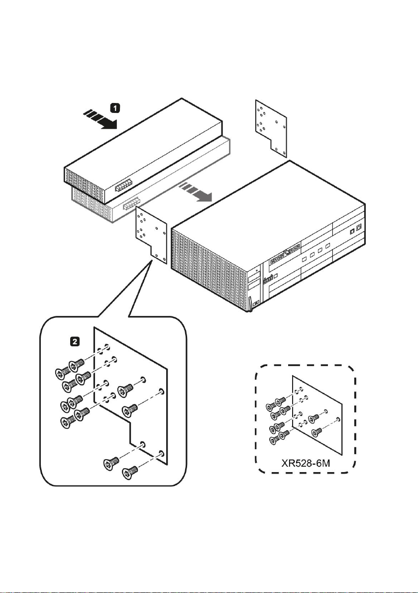
Figure 4-1 Rear panel mounting of the SCALANCE XR552-12M. SCALANCE
XR528-6M is used analogously.
Power supply unit PS598-1 for SCALANCE XR500
A5E03275848-04, 05/2013 9
Page 12

Mounting
On the rear panel of a SCALANCE XR500, there are sockets for the direct
connection of a maximum of two PS598-1 power supply units. On the rear of the
PS598-1 there is a corresponding plug. Follow the steps below to install the PS598-1
on the rear panel of a SCALANCE XR500:
1. Fit the PS598-1 and the SCALANCE XR500 together. The two devices are
equipped with positioning elements that must engage during installation and
protect the plug from excessive bending strain.
2. Screw the two devices to the mounting plates supplied with the main device. The
maximum tightening torque of the screws is 0.5 Nm.
Power supply unit PS598-1 for SCALANCE XR500
10 A5E03275848-04, 05/2013
Page 13
NOTICE
Connect and disconnect the power supply unit only when it is not energized!
The PS598-1 is not capable of hot plugging. Connecting or disconnecting the
PS598-1 when the 100 to 240 VAC power supply is on can damage the PS598-1
and the SCALANCE XR500.
Before connecting or disconnecting the PS598-1, make sure that the switch for the
input voltage is set to position "0".
NOTICE
CAUTION/DOUBLE POLE
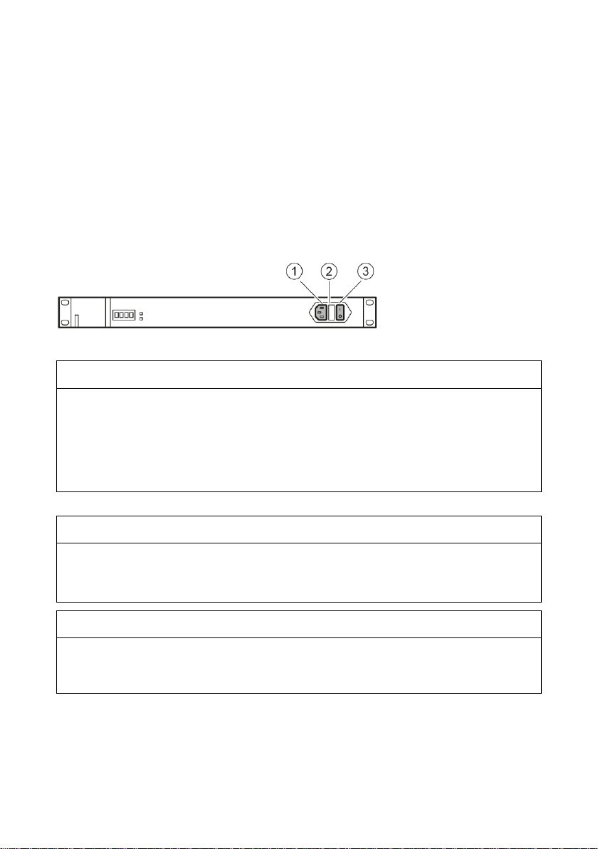
The fuses FUSE1 and FUSE2 are in the fuse holder (position ②). The fuses are of
the type F6.3AH / 250 VAC.
NOTICE
Overvoltage protection for the power supply cables
If there is any possible overload of the power supply cables, suitable overvoltage
protection is necessary. Refer to the values on the type plate.
5 Connection
5.1 Connecting devices with 100 to 240 VAC
power supply
Switches for the input voltage
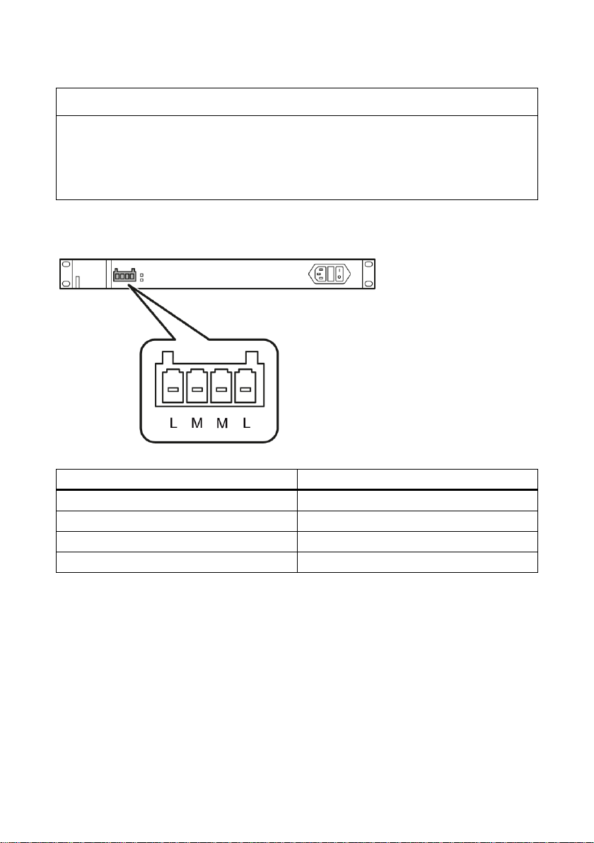
The socket X1 (position ①) and the switch S1 Power (position ③) for the input
voltage are located on the right-hand side of the front panel of the housing:
Power supply unit PS598-1 for SCALANCE XR500
A5E03275848-04, 05/2013 11
Page 14
Connection
NOTICE
Reliable grounding
Reliable grounding of the devices mounted in the rack must be guaranteed. This
applies, in particular, to power supply cables that are not connected directly to the
power supply circuit. With the PS598-1, the IEC power connector (IEC 60320-1)
provides the connection to protective earth.
Contact
Assignment
L
+24 VDC
M
Ground
M
Ground
L
+24 VDC
Pin assignment of the X2 socket on the front
Power supply unit PS598-1 for SCALANCE XR500
12 A5E03275848-04, 05/2013
Page 15
Connection
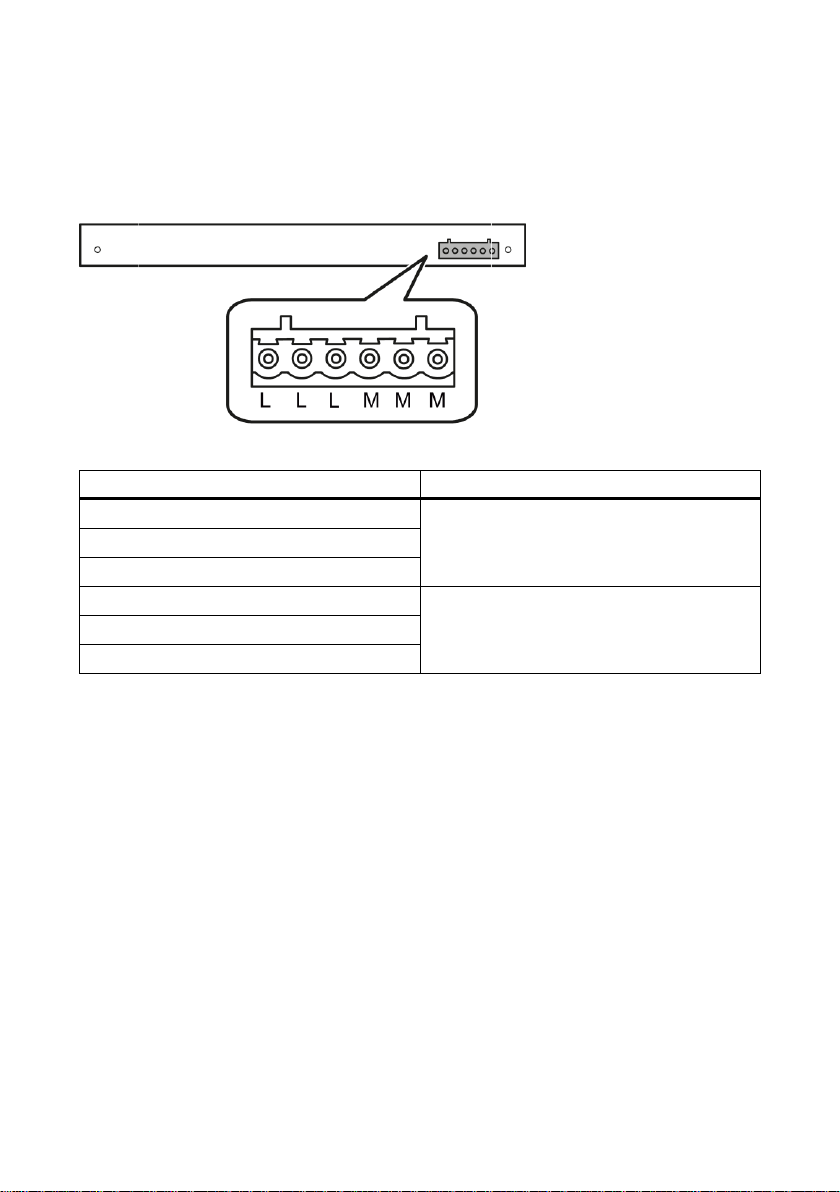
Contact
Assignment
L
+24 VDC
L
L
M
Ground
M
M
Pin assignment of the X3 plug on the rear
Connector X3 is located on the back of the PS598-1. Connector X3 is intended only
to connect the PS598-1 directly to an XR500.
Power supply unit PS598-1 for SCALANCE XR500
A5E03275848-04, 05/2013 13
Page 16
Connection
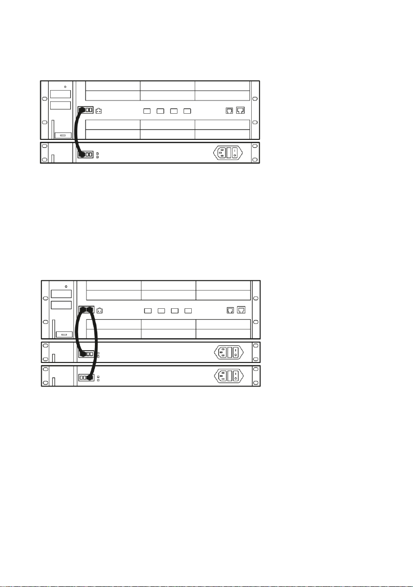
One PS598-1 per device, no redundancy
Figure 5-1 Connecting a power supply unit to a SCALANCE XR552-12M.
SCALANCE XR528-6M is used analogously.
Connect the SCALANCE XR500 and the PS598-1 with one cable for 24 VDC and a
cable for ground. As an alternative, you can also mount the PS598-1 on the back of
the SCALANCE XR500 and secure it with screws. In this case, no extra cables are
necessary. You will find detailed information in the section "Installation".
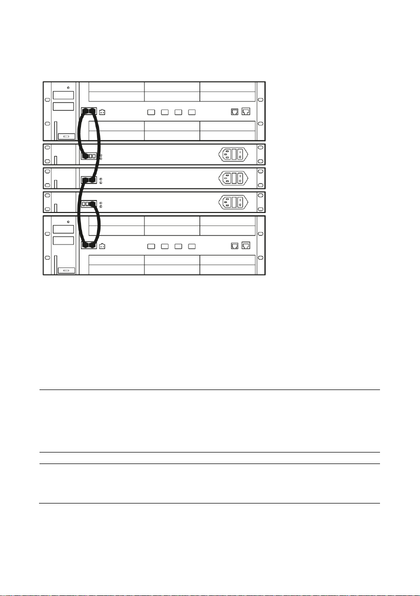
Two PS598-1 per device, 1-out-of-2 redundancy
Figure 5-2 Connecting two power supply units to a SCALANCE XR552-12M.
SCALANCE XR528-6M is used analogously.
Connect the SCALANCE XR500 and the PS598-1 with one cable for 24 VDC and a
cable for ground. As an alternative, you can also mount the two PS598-1 units on the
back of the SCALANCE XR500 and secure it with screws. In this case, no extra
cables are necessary. You will find detailed information in the section "Mounting
(Page 6)". It is also possible to operate the SCALANCE XR500 even after the failure
of a PS598-1. The SCALANCE XR500 detects the failure of a power source and
signals the failure. The PS598-1 units share the applied load automatically and
uniformly.
Power supply unit PS598-1 for SCALANCE XR500
14 A5E03275848-04, 05/2013
Page 17
Connection
Note
Two connectors for the 24 VDC output voltage
The PS598-1 has two connectors with the output voltage 24 VDC. Note that you can
only use the connector on the front or the connector on the rear of the PS598-1. You
cannot operate the device with the connectors on the front and rear at the same time.
Note
To wire up the power supply connector, use copper cable of the category 14 AWG to
10 AWG or cable with a cross-sectional area of 1.5 to to 4 mm2.
Three PS598-1 units for two devices - 2-out-of-3 redundancy
Figure 5-3 Connecting three power supply units to a SCALANCE XR552-12M.
SCALANCE XR528-6M is used analogously.
Connect each SCALANCE XR500 to its own PS598-1. In addition to this, connect
both SCALANCE XR500 devices to the third PS598-1. Both SCALANCE XR500
devices can now continue to operate after the failure of one PS598-1. The
SCALANCE XR500 detects the failure of a power source and signals the failure. The
PS598-1 units share the applied load automatically and uniformly.
Power supply unit PS598-1 for SCALANCE XR500
A5E03275848-04, 05/2013 15
Page 18
Connection
WARNING
Safety notice for connectors with LAN (Local Area Network) marking
A LAN or LAN segment, with all its associated interconnected equipment, shall be
entirely contained within a single low-voltage power distribution and within a single
building. The LAN is considered to be in an "environment A" according to
IEEE802.3
or "environment 0" according to IEC TR 62102, respectively.
Never connect directly to TNV-circuits (Telephone Network) or
WAN (Wide Area Network).
In areas subject to the NEC or CEC:
5.2 LED display
LED display
A PS598-1 has two LEDs each, one green and one red. If the green LEDs is lit
(24V OK), the output voltage is correctly applied. If the red LED is lit (SHUT DOWN)
an error has occurred.
Possible errors/faults:
● The output voltage is not correct.
● Temperature of the PS598-1 is too high.
Power supply unit PS598-1 for SCALANCE XR500
16 A5E03275848-04, 05/2013
Page 19

NOTICE
A badly contaminated air filter reduces air flow and can cause the device to be
damaged.
Check the degree of contamination of the air filter regularly and clean it when
necessary.
6 Upkeep and maintenance
The PS598-1 has a service panel, behind which there is a removable air filter. The air
filter can be replaced during operation.
Procedure
1. Open the service panel.
2. Take the air filter out of the device.
3. Clean the air filter.
4. Place the cleaned air filter in the device again.
5. Close the panel.
Power supply unit PS598-1 for SCALANCE XR500
A5E03275848-04, 05/2013 17
Page 20

Interface
Execution
Power
● 4-pin terminal block for 2 x 24 VDC on the front of the device.
● Plug on the rear of the housing for direct connection to a
SCALANCE XR500.
Property
Value / version / exists
Dimensions without brackets for rack
mounting
(W x H x D)
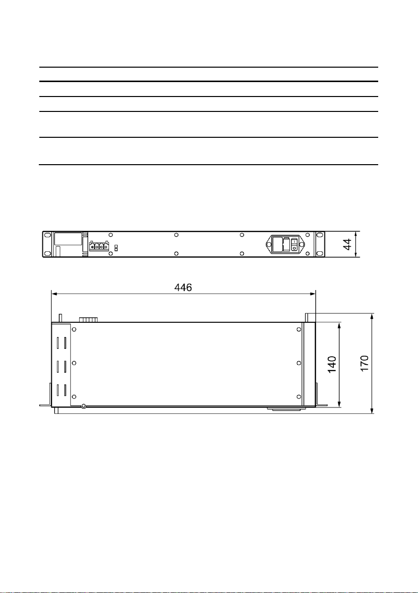
446 x 44 x 140 mm
(1 height unit)
Weight
1700 g
Surface of the housing
Powder coating
Degree of protection
IP20 (with closed panel in housing)
Installation in a 483 mm rack (19" rack)
Yes
DIN rail mounting
No
S7-300 standard rail mounting
No
Wall mounting
No
Property
Value
Rated power
300 W
Input voltage
100 to 240 VAC / 50/60 Hz
Output voltage
24 VDC
Output current
12.5 A
Input current at 300 W
3,6 ... 1.6 A
Overcurrent protection of the power supply
F6.3 AH / 250 VAC
7 Technical data
Device variants
The following technical specifications apply to the following device:
● PS598-1
Connectors
Construction
Electrical data
Power supply unit PS598-1 for SCALANCE XR500
18 A5E03275848-04, 05/2013
Page 21
Environmental conditions
Property
Value
Transportation/storage temperature
-40 °C to +85 °C
Operating temperature
0 °C to +60 °C
Maximum relative humidity
in operation at 25 °C
< 95 % no condensation
Operating altitude above sea level
depending on ambient temperature
● 2000 m at max. 56 °C
● 3000 m at max. 50 °C
8 Dimension drawings
View from front and above
Dimension drawings
Dimensions are specified in mm.
Power supply unit PS598-1 for SCALANCE XR500
A5E03275848-04, 05/2013 19
Page 22
Note
Issued approvals on the type plate of the device
The specified approvals apply only when the corresponding mark is printed on the
product. You can check which of the following approvals have been granted for your
product by the markings on the type plate.
Field of application
Requirements
Emission
Immunity to interference
Industry
EN 61000-6-4 : 2007
EN 61000-6-2 : 2005
WARNING
Personal injury and property damage can occur
The installation of expansions that are not approved for SIMATIC NET products or
their target systems may violate the requirements and regulations for safety and
electromagnetic compatibility.
Only use expansions that are approved for the system.
9 Approvals
The SIMATIC NET products described in these Operating Instructions have the
approvals listed below.
EC directives
SIMATIC NET products meet the requirements and aims of the following EC
directives.
9.1 EMC directive
EMC directive (electromagnetic compatibility)
The SIMATIC NET products described in these operating instructions meet the
requirements of EC directive 2004/108/EC "Electromagnetic Compatibility" for the
following areas of application:
C-TICK
The product meets the requirements of the AS/NZS 2064 standard (Class A).
Power supply unit PS598-1 for SCALANCE XR500
20 A5E03275848-04, 05/2013
Page 23

● Keep to the installation guidelines
Note
The product was tested with a device that also complies with the standards
listed above.
If the product is operated with a device that does not meet these standards,
there is no guarantee that the corresponding values will be adhered to.
The product meets the requirements if you adhere to the installation and safety
instructions contained in this documentation and in the following documentation
when installing and operating the product.
● You can always find the latest documentation on the Internet
The current descriptions of the currently available products can always be found
on the Internet under the specified entry IDs/Internet pages:
– SIMATIC NET Industrial Ethernet Network manual
ID = 27069465
(http://support.automation.siemens.com/WW/view/en/27069465)
– EMC Installation Guideline, Planning Guide
ID = 28518276
(http://support.automation.siemens.com/WW/view/en/28518276)
– Working on the product
To protect the product from electrostatic discharge, personnel must first
discharge any electrostatic charge from their body before touching the
product.
Approvals
Low voltage equipment directive
Devices supplied with 100 to 240 VAC meet the requirements of the directive
2006/95/EC "Electrical Equipment Designed for Use within Certain Voltage Limits”
(Low Voltage Equipment Directive). Conformity attested by compliance with the
standard EN 60950-1:2010.
cULus Approval for Information Technology Equipment
cULus Listed I. T. E.
Underwriters Laboratories Inc. complying with
● UL 60950-1 (Information Technology Equipment)
● CSA C22.2 No. 60950-1-03
Power supply unit PS598-1 for SCALANCE XR500
A5E03275848-04, 05/2013 21
Page 24
Approvals
Device:
SCALANCE
IEC 60068-2-6 vibration
*)
IEC 60068-2-27 shock
IEC 60068-2-6 vibration
5 – 9 Hz: 3.5 mm
9 – 150 Hz: 1 g
1 octave/min, 20
sweeps
15 g, 11 ms duration
6 shocks per axis
10 – 58 Hz: 0.075 mm
85 – 150 Hz: 1 g
1 octave/min, 20 sweeps
PS598-1 ● ●
●
*) Note: When rack mounted with four securing points
Trademarks
All names identified by ® are registered trademarks of Siemens AG. The remaining trademarks
in this publication may be trademarks whose use by third parties for their own purposes could
violate the rights of the owner.
Disclaimer of Liability
We have reviewed the contents of this publication to ensure consistency with the hardware and
software described. Since variance cannot be precluded entirely, we cannot guarantee full
consistency. However, the information in this publication is reviewed regularly and any
necessary corrections are included in subsequent editions.
Siemens AG
Industry Sector
Postfach 48 48
90026 NÜRNBERG
Power supply unit PS598-1 for SCALANCE XR500
A5E03275848, 05/2013
EU declaration of conformity
You will find the EU declaration of conformity for these products on the Internet under
the following entry IDs/Internet page specified here:
ID = 57026840 (http://support.automation.siemens.com/WW/view/en/57026840)
● Entry list
● Entry type "Certificates"
● Type of certificate "Declaration of Conformity"
Example German: "EG-Konformitätserklärung SCALANCE XR552-12M",
Example English: "Declaration of Conformity SCALANCE XR552-12M".
9.2 Mechanical stability (in operation)
Power supply unit PS598-1 for SCALANCE XR500
22 A5E03275848-04, 05/2013
 Loading...